US5926751A - Method and apparatus for receiving communication signals - Google Patents
Method and apparatus for receiving communication signalsDownload PDFInfo
- Publication number
- US5926751A US5926751AUS08/803,186US80318697AUS5926751AUS 5926751 AUS5926751 AUS 5926751AUS 80318697 AUS80318697 AUS 80318697AUS 5926751 AUS5926751 AUS 5926751A
- Authority
- US
- United States
- Prior art keywords
- filter
- band
- communication signals
- input
- mixer
- Prior art date
- Legal status (The legal status is an assumption and is not a legal conclusion. Google has not performed a legal analysis and makes no representation as to the accuracy of the status listed.)
- Expired - Lifetime
Links
- 238000004891communicationMethods0.000titleclaimsabstractdescription57
- 238000000034methodMethods0.000titleclaimsabstractdescription10
- 230000008878couplingEffects0.000claims4
- 238000010168coupling processMethods0.000claims4
- 238000005859coupling reactionMethods0.000claims4
- 238000002347injectionMethods0.000abstractdescription6
- 239000007924injectionSubstances0.000abstractdescription6
- 230000009977dual effectEffects0.000abstractdescription4
- 239000003990capacitorSubstances0.000description15
- 230000005540biological transmissionEffects0.000description10
- 238000010586diagramMethods0.000description9
- 239000000919ceramicSubstances0.000description6
- 230000001413cellular effectEffects0.000description4
- 238000002955isolationMethods0.000description3
- 238000013461designMethods0.000description1
- 230000006870functionEffects0.000description1
- 238000012986modificationMethods0.000description1
- 230000004048modificationEffects0.000description1
- 238000012545processingMethods0.000description1
- 238000001228spectrumMethods0.000description1
Images


Classifications
- H—ELECTRICITY
- H04—ELECTRIC COMMUNICATION TECHNIQUE
- H04B—TRANSMISSION
- H04B1/00—Details of transmission systems, not covered by a single one of groups H04B3/00 - H04B13/00; Details of transmission systems not characterised by the medium used for transmission
- H04B1/005—Details of transmission systems, not covered by a single one of groups H04B3/00 - H04B13/00; Details of transmission systems not characterised by the medium used for transmission adapting radio receivers, transmitters andtransceivers for operation on two or more bands, i.e. frequency ranges
- H04B1/0053—Details of transmission systems, not covered by a single one of groups H04B3/00 - H04B13/00; Details of transmission systems not characterised by the medium used for transmission adapting radio receivers, transmitters andtransceivers for operation on two or more bands, i.e. frequency ranges with common antenna for more than one band
- H04B1/006—Details of transmission systems, not covered by a single one of groups H04B3/00 - H04B13/00; Details of transmission systems not characterised by the medium used for transmission adapting radio receivers, transmitters andtransceivers for operation on two or more bands, i.e. frequency ranges with common antenna for more than one band using switches for selecting the desired band
- H—ELECTRICITY
- H03—ELECTRONIC CIRCUITRY
- H03D—DEMODULATION OR TRANSFERENCE OF MODULATION FROM ONE CARRIER TO ANOTHER
- H03D7/00—Transference of modulation from one carrier to another, e.g. frequency-changing
- H03D7/12—Transference of modulation from one carrier to another, e.g. frequency-changing by means of semiconductor devices having more than two electrodes
- H—ELECTRICITY
- H03—ELECTRONIC CIRCUITRY
- H03J—TUNING RESONANT CIRCUITS; SELECTING RESONANT CIRCUITS
- H03J1/00—Details of adjusting, driving, indicating, or mechanical control arrangements for resonant circuits in general
- H—ELECTRICITY
- H03—ELECTRONIC CIRCUITRY
- H03J—TUNING RESONANT CIRCUITS; SELECTING RESONANT CIRCUITS
- H03J1/00—Details of adjusting, driving, indicating, or mechanical control arrangements for resonant circuits in general
- H03J1/0008—Details of adjusting, driving, indicating, or mechanical control arrangements for resonant circuits in general using a central processing unit, e.g. a microprocessor
- H—ELECTRICITY
- H04—ELECTRIC COMMUNICATION TECHNIQUE
- H04B—TRANSMISSION
- H04B1/00—Details of transmission systems, not covered by a single one of groups H04B3/00 - H04B13/00; Details of transmission systems not characterised by the medium used for transmission
- H04B1/005—Details of transmission systems, not covered by a single one of groups H04B3/00 - H04B13/00; Details of transmission systems not characterised by the medium used for transmission adapting radio receivers, transmitters andtransceivers for operation on two or more bands, i.e. frequency ranges
- H04B1/0053—Details of transmission systems, not covered by a single one of groups H04B3/00 - H04B13/00; Details of transmission systems not characterised by the medium used for transmission adapting radio receivers, transmitters andtransceivers for operation on two or more bands, i.e. frequency ranges with common antenna for more than one band
- H04B1/0057—Details of transmission systems, not covered by a single one of groups H04B3/00 - H04B13/00; Details of transmission systems not characterised by the medium used for transmission adapting radio receivers, transmitters andtransceivers for operation on two or more bands, i.e. frequency ranges with common antenna for more than one band using diplexing or multiplexing filters for selecting the desired band
- H—ELECTRICITY
- H04—ELECTRIC COMMUNICATION TECHNIQUE
- H04B—TRANSMISSION
- H04B1/00—Details of transmission systems, not covered by a single one of groups H04B3/00 - H04B13/00; Details of transmission systems not characterised by the medium used for transmission
- H04B1/38—Transceivers, i.e. devices in which transmitter and receiver form a structural unit and in which at least one part is used for functions of transmitting and receiving
- H04B1/40—Circuits
Definitions
- the present inventionis generally related to communication devices, and more particularly, to a method and apparatus for receiving communication signals.
- FIG. 1is block diagram of a communication device according to the present invention
- FIG. 2is a block diagram of receiver 127 of FIG. 1 according to the present invention.
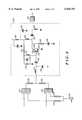
- FIG. 3is schematic diagram of mixer 234 according to the present invention.
- FIG. 4is a block diagram of receiver 127 of FIG. 1 according to an alternate embodiment of the present invention.
- FIG. 5is schematic diagram of mixer 234 according to an alternate embodiment of the present invention.
- a method and apparatusenables a communication device to operate in multiple bands, such as GSM 900 MHz, DCS 1800 MHz, and PCS 1900 MHz bands by eliminating the need for a mixer for each band.
- GSM/DCS 1800 radiotelephonefor example, the local oscillator (LO) injection frequencies for both GSM and DCS bands are provided to a mixer through the use of combination filters.
- LOlocal oscillator
- the combination RX/LO filtersone for each GSM and DCS bands, are designed with RX and LO input ports and a common RX/LO output port.
- the common output ports of the GSM RX/LO combination filter and DCS RX/LO combination filterare duplexed to the input of the mixer. Because the duplexing requirements between the RX and LO injection frequencies are accommodated by the combination filters, the circuit design reduces the number of duplex lines to the mixer from six to two for a dual band communication device and from ten to four for a tri-band communication device. Also, the input impedance matching of the mixer is designed to match the impedance for the received signals in each band, as well as provide an RF trap at the IF frequency. Finally, the output circuit of the mixer provides a low impedance to the RF input frequency and also a match to the input of the IF filter.
- FIG. 1a block diagram of a wireless communication device such as a cellular radiotelephone incorporating the present invention is shown.
- a frame generator ASIC 101such as a CMOS ASIC available from Motorola, Inc.
- a microprocessor 103such as a 68HC11 microprocessor also available from Motorola, Inc., combine to generate the necessary communication protocol for operating in a cellular system.
- Microprocessor 103uses memory 104 comprising RAM 105, EEPROM 107, and ROM 109, preferably consolidated in one package 111, to execute the steps necessary to generate the protocol and to perform other functions for the wireless communication device, such as writing to a display 113, accepting information from a keypad 115, accepting input/output information by way of a connector 116 according to the present invention, controlling a frequency synthesizer 125, or performing steps necessary to amplify a signal according to the method of the present invention.
- ASIC 101processes audio transformed by audio circuitry 119 from a microphone 117 and to a speaker 121.
- a transceiverprocesses the radio frequency signals.
- a transmitter 123transmits through an antenna 129 using carrier frequencies produced by a frequency synthesizer 125.
- Information received by the communication device's antenna 129enters receiver 127 which demodulates the symbols using the carrier frequencies from frequency synthesizer 125.
- the communication devicemay optionally include a message receiver and storage device 130 including digital signal processing means.
- the message receiver and storage devicecould be, for example, a digital answering machine or a paging receiver.
- FIG. 2a block diagram shows a receiver 127 for a dual-band radiotelephone according to the present invention.
- An RF signal received by antenna 129is coupled to a matching circuit 201 comprising a first RF matching block 202 and a second RF matching block 204.
- the RF matching circuitsare designed to provide the proper impedance match to the receiver, depending upon the frequency of the received signal.
- the RF signalis then coupled to an antenna switch 206 which is controlled by an antenna switch control circuit 208.
- the antenna switch controlenables the RF signals to be received and transmitted by an accessory coupled to the communication device by connector 210.
- a hands-free accessoryfor enabling hands-free operation in a vehicle could be coupled to connector 210 according to the present invention.
- the received RF signalis then provided to a plurality of paths of the receiver by a line 212. That is, a separate path will be provided for each band, depending upon the number of bands available to the communication device.
- line 212is coupled to a transmission line 214 which provides the RF signal to a first filter 216.
- filter 216could be a three pole bandpass ceramic filter used as a preselector filter.
- the ceramic filtercould be tuned to pass RF signals at 935 to 960 MHz in the GSM receive band.
- the filter signalis then transmitted to a preamplifier 218.
- preamplifier 218includes an enable line 220 for enabling or disabling the preamplifier.
- the enable linecontrols a transistor to provide isolation to the mixer from transmitter energy and other spurious frequencies.
- the output of the preamplifier 218is coupled to a combination filter 222 at a first input 224 and a LO injection frequency at a second input 226 by way of a transmission line 230 coupled to a voltage controlled oscillator 228.
- a combined ceramic monoblock filtercould receive 935-965 MHz in the GSM band and LO injection 720-745 MHz.
- a common output port 232 of filter 222is coupled to a mixer 234 by way of transmission line 236.
- Line 212is also coupled to a second RF path by way of a transmission line 240 which is coupled to a second filter 242.
- the second filtercould also be a three pole bandpass ceramic filter, for example, used a preselector filter.
- the output of filter 242is coupled to a second preamplifier 244.
- preamplifier 244also has an enable line 246 to provide isolation to the mixer from transmitter energy and other spurious frequencies.
- the output of preamplifier 244is coupled to a second combination filter 246 at a third input 248.
- the combined filter 246is also coupled to receive the LO frequency at a fourth input 250 by way of transmission line 252.
- a combined output 254is also coupled to mixer 234 by way of a transmission line 256.
- mixer 234generates an intermediate frequency (IF) signal at an output 258.
- the IF signalwhich is preferably 215 MHz is provided to a filter 260, such as a SAW bandpass filter.
- FIG. 3a circuit diagram shows mixer 234 of FIG. 2.
- the mixeris designed to operate in a dual band radiotelephone, such as a phone adapted to operate at both DCS 1800 MHz and GSM 900 MHz frequencies bands.
- the mixer input circuitis designed to match 50 ohm in all bands and to filter the output 215 MHz IF signal.
- the mixer output circuitis designed with a matching circuit to the 215 MHz filter and a wide band strip line LC trap circuit to filter the input RF signals (for each band) for optimum mixer performance.
- the output signals of the combination filtersare coupled to an inductor 302 of mixer 234.
- the inductoris coupled to a capacitor 304 to ground and to a transistor 308 at a base 310.
- An inductor 312is also coupled to base 310.
- Inductor 302 and capacitor 304 along with capacitor 306 and inductor 312are selected to provide an RF match at the input of the mixer. That is, the values are selected to provide a 50 ohm impedance for each of the received band, such as 900 Mhz and 1800 MHz.
- inductor 302is preferably approximately 3.3 nanohenries (nH)
- capacitor 304is approximately 0.5 picofarads (pF)
- capacitor 306is approximatel 2 pf
- inductor 312is approximately 5.6 nH.
- the collector 314 of transistor 308is coupled to a transmission line 318 which is coupled to ground by way of a capacitor 320.
- the collectoris also coupled to a capacitor 322, which is coupled to an inductor 324 to ground and filter 260.
- an inductor 326is coupled between collector 314 and a resistor 332 coupled to inductor 312.
- Capacitor 322 and inductor 326are selected to provide impedance matching to the IF filter 260.
- the values of strip line 318 and capacitor 320are selected to provide an LC trap circuit to filter the RF input signals for optimum mixer performance.
- strip line 318preferably has a width of approximately 20 mils and a length of approximately 350 mils, providing an inductance of approximately 3 nH.
- Capacitor 320preferably is a 4.7 pF capacitor, while inductor 326 is approximately 27 nH.
- the mixeris designed to provide an IF match to filter 260.
- Inductor 326 and capacitor 322are preferably selected to provide low impedance to the IF frequency of the mixer. For a 215 MHz IF frequency, capacitor 322 is approximately 33 pF while inductor 326 is approximately 27 nH.
- an IF trapis provided to prevent the intermediate frequency from being fed back to transistor 308.
- a capacitor 334 coupled between inductor 312 and groundprovides a trap for the IF signal. For an IF frequency of 215 MHz, inductor 312 is approximately 5.6 nH and capacitor 334 is approximately 68 pF.
- an additional RF pathcan be provided for receiving signals from a third communication system.
- the communication devicecould also be adapted to receive PCS 1900 signals.
- line 212could be coupled to a third RF stage by way of transmission lines 451 and 414 which are coupled to a filter 416.
- filter 416could be a three pole bandpass ceramic filter used as a preselector filter. The ceramic filter could be tuned to pass RF signals at 1930-1990 MHz in the PCS 1900 receive band.
- the filtered signalis then transmitted to a preamplifier 418.
- preamplifier 418includes an enable line 420 for enabling or disabling the preamplifier.
- the enable linecontrols a transistor to provide isolation to the mixer from transmitter energy and other spurious frequencies.
- the output of the preamplifier 418is coupled to a combination filter 422 at a fifth input 424 and a LO injection frequency at a sixth input 426 by way of transmission lines 430 and 452 coupled to a voltage controlled oscillator 228.
- the combination output 432 of filter 422is coupled to mixer 234 by way of transmission lines 436 and 453.
- FIG. 5a circuit diagram shows mixer 234 of FIG. 4.
- the mixeris designed to operate at GSM 900 Mhz, DCS 1800 MHZ and PCS 1800 Mhz frequency bands in a tri-band radiotelephone.
- the mixer inputis designed to match at 50 ohms in all three frequency bands, and to filter the output 215 Mhz IF signal.
- the mixer output circuitis designed with a matching circuit to the 215 Mhz filter in a wide band strip line LC trap circuit to filter the input RF signals (for all three bands) for optimum mixer performance.
- the remaining portions of the FIGS. 4 and 5are identical to FIGS. 2 and 3, and the functionality of those sections will not be repeated again here.
Landscapes
- Engineering & Computer Science (AREA)
- Computer Networks & Wireless Communication (AREA)
- Signal Processing (AREA)
- Power Engineering (AREA)
- Computer Hardware Design (AREA)
- Microelectronics & Electronic Packaging (AREA)
- Transceivers (AREA)
- Superheterodyne Receivers (AREA)
Abstract
Description
Claims (9)
Priority Applications (8)
| Application Number | Priority Date | Filing Date | Title |
|---|---|---|---|
| US08/803,186US5926751A (en) | 1997-02-19 | 1997-02-19 | Method and apparatus for receiving communication signals |
| GB9801264AGB2322491B (en) | 1997-02-19 | 1998-01-21 | Method and apparatus for receiving communication signals |
| FR9801198AFR2759827B1 (en) | 1997-02-19 | 1998-02-03 | METHOD AND DEVICE FOR RECEIVING COMMUNICATION SIGNALS |
| DE19806096ADE19806096C2 (en) | 1997-02-19 | 1998-02-14 | Method and device for receiving data transmission signals |
| MXPA/A/1998/001327AMXPA98001327A (en) | 1997-02-19 | 1998-02-18 | Method and apparatus for receiving signals of communication |
| KR1019980004917AKR100262922B1 (en) | 1997-02-19 | 1998-02-18 | Method and apparatus for receiving communication signals |
| JP10052939AJPH10242882A (en) | 1997-02-19 | 1998-02-18 | Method and device for receiving communication signal |
| RU98104139/09ARU2214050C2 (en) | 1997-02-19 | 1998-02-18 | Device and method for receiving communication signals from plurality of radio-frequency bands (alternatives) |
Applications Claiming Priority (1)
| Application Number | Priority Date | Filing Date | Title |
|---|---|---|---|
| US08/803,186US5926751A (en) | 1997-02-19 | 1997-02-19 | Method and apparatus for receiving communication signals |
Publications (1)
| Publication Number | Publication Date |
|---|---|
| US5926751Atrue US5926751A (en) | 1999-07-20 |
Family
ID=25185823
Family Applications (1)
| Application Number | Title | Priority Date | Filing Date |
|---|---|---|---|
| US08/803,186Expired - LifetimeUS5926751A (en) | 1997-02-19 | 1997-02-19 | Method and apparatus for receiving communication signals |
Country Status (7)
| Country | Link |
|---|---|
| US (1) | US5926751A (en) |
| JP (1) | JPH10242882A (en) |
| KR (1) | KR100262922B1 (en) |
| DE (1) | DE19806096C2 (en) |
| FR (1) | FR2759827B1 (en) |
| GB (1) | GB2322491B (en) |
| RU (1) | RU2214050C2 (en) |
Cited By (43)
| Publication number | Priority date | Publication date | Assignee | Title |
|---|---|---|---|---|
| US6029052A (en)* | 1997-07-01 | 2000-02-22 | Telefonaktiebolaget Lm Ericsson | Multiple-mode direct conversion receiver |
| WO2000019623A1 (en)* | 1998-09-30 | 2000-04-06 | Conexant Systems, Inc. | Using a single side band mixer to reject image signals in a wireless station |
| US6125271A (en)* | 1998-03-06 | 2000-09-26 | Conexant Systems, Inc. | Front end filter circuitry for a dual band GSM/DCS cellular phone |
| US6134427A (en)* | 1998-09-30 | 2000-10-17 | Conexant Systems, Inc. | Using a single low-noise amplifier in a multi-band wireless station |
| EP1081877A1 (en)* | 1999-09-04 | 2001-03-07 | Siemens Aktiengesellschaft | Mobile station and method for setting output power during frequency redefinition between bands |
| US6298224B1 (en)* | 1999-02-22 | 2001-10-02 | Motorola, Inc. | Multiple frequency band receiver |
| US6442400B1 (en)* | 1997-11-06 | 2002-08-27 | Telefonaktiebolaget L M Ericsson (Publ) | Portable electronic communication device with dual-band antenna system |
| US6526263B1 (en)* | 1998-08-28 | 2003-02-25 | Nec Corporation | Antenna impedance adjuster |
| US6591093B1 (en) | 1999-10-25 | 2003-07-08 | Motorola, Inc. | Circuit and method for frequency translation |
| KR100396779B1 (en)* | 2001-07-12 | 2003-09-02 | 엘지전자 주식회사 | Mobile communication apparatus |
| GB2389258A (en)* | 2002-04-02 | 2003-12-03 | Microcell S A Luxembourg Zweig | Filter arrangement in a multi-band mobile terminal device |
| EP1391986A1 (en)* | 2002-08-21 | 2004-02-25 | TDK Corporation | Multi-band amplifier |
| US20040069571A1 (en)* | 2002-10-09 | 2004-04-15 | Lee Elliot W. | Vehicle drip tray and pet waste pan |
| US6735426B1 (en)* | 2001-01-25 | 2004-05-11 | National Semiconductor Corporation | Multiple-band wireless transceiver with quadrature conversion transmitter and receiver circuits |
| US6754508B1 (en)* | 2001-01-25 | 2004-06-22 | National Semiconductor Corporation | Multiple-band wireless transceiver with quadrature conversion transmitter and receiver circuits |
| US6999716B1 (en)* | 1999-03-23 | 2006-02-14 | Fahrenheit Thermoscope, Llc | Dual mode radio frequency reception device and corresponding multimedia receiver |
| KR100631272B1 (en)* | 1999-09-14 | 2006-10-02 | 엘지전자 주식회사 | Multi-mode mobile communication terminal |
| US20060223487A1 (en)* | 2005-04-04 | 2006-10-05 | Freescale Semiconductor, Inc. | Multi-band mixer and quadrature signal generator for a multi-mode radio receiver |
| US20060281426A1 (en)* | 2005-06-14 | 2006-12-14 | Galan Ariel L | Architecture for a receiver front end |
| KR100822475B1 (en) | 2006-10-19 | 2008-04-16 | 삼성전자주식회사 | Active antenna capable of transmitting and receiving low frequency radio signals and a mobile communication terminal having the same |
| US20150042537A1 (en)* | 2000-07-20 | 2015-02-12 | Blackberry Limited | Tunable microwave devices with auto-adjusting matching circuit |
| US20160248453A1 (en)* | 2015-02-24 | 2016-08-25 | Renesas Electronics Corporation | Semiconductor device and radio communication device |
| US9548716B2 (en) | 2010-03-22 | 2017-01-17 | Blackberry Limited | Method and apparatus for adapting a variable impedance network |
| US9564944B2 (en) | 2010-04-20 | 2017-02-07 | Blackberry Limited | Method and apparatus for managing interference in a communication device |
| US9671765B2 (en) | 2012-06-01 | 2017-06-06 | Blackberry Limited | Methods and apparatus for tuning circuit components of a communication device |
| US9698748B2 (en) | 2007-04-23 | 2017-07-04 | Blackberry Limited | Adaptive impedance matching |
| US9698758B2 (en) | 2008-09-24 | 2017-07-04 | Blackberry Limited | Methods for tuning an adaptive impedance matching network with a look-up table |
| US9698858B2 (en) | 2011-02-18 | 2017-07-04 | Blackberry Limited | Method and apparatus for radio antenna frequency tuning |
| US9716311B2 (en) | 2011-05-16 | 2017-07-25 | Blackberry Limited | Method and apparatus for tuning a communication device |
| US9722577B2 (en) | 2006-11-08 | 2017-08-01 | Blackberry Limited | Method and apparatus for adaptive impedance matching |
| US9768810B2 (en) | 2012-12-21 | 2017-09-19 | Blackberry Limited | Method and apparatus for adjusting the timing of radio antenna tuning |
| US9853363B2 (en) | 2012-07-06 | 2017-12-26 | Blackberry Limited | Methods and apparatus to control mutual coupling between antennas |
| US9853663B2 (en) | 2009-10-10 | 2017-12-26 | Blackberry Limited | Method and apparatus for managing operations of a communication device |
| US9853622B2 (en) | 2006-01-14 | 2017-12-26 | Blackberry Limited | Adaptive matching network |
| US9941910B2 (en) | 2012-07-19 | 2018-04-10 | Blackberry Limited | Method and apparatus for antenna tuning and power consumption management in a communication device |
| US10020828B2 (en) | 2006-11-08 | 2018-07-10 | Blackberry Limited | Adaptive impedance matching apparatus, system and method with improved dynamic range |
| US10163574B2 (en) | 2005-11-14 | 2018-12-25 | Blackberry Limited | Thin films capacitors |
| USRE47412E1 (en) | 2007-11-14 | 2019-05-28 | Blackberry Limited | Tuning matching circuits for transmitter and receiver bands as a function of the transmitter metrics |
| US10404295B2 (en) | 2012-12-21 | 2019-09-03 | Blackberry Limited | Method and apparatus for adjusting the timing of radio antenna tuning |
| US10624091B2 (en) | 2011-08-05 | 2020-04-14 | Blackberry Limited | Method and apparatus for band tuning in a communication device |
| US10651918B2 (en) | 2014-12-16 | 2020-05-12 | Nxp Usa, Inc. | Method and apparatus for antenna selection |
| US11569850B2 (en) | 2019-03-22 | 2023-01-31 | Vivo Mobile Communication Co., Ltd. | Radio frequency front-end circuit and controller |
| US11757484B2 (en) | 2019-03-22 | 2023-09-12 | Vivo Mobile Communication Co., Ltd. | Radio frequency front-end circuit and mobile terminal |
Families Citing this family (6)
| Publication number | Priority date | Publication date | Assignee | Title |
|---|---|---|---|---|
| JP3304898B2 (en) | 1998-11-20 | 2002-07-22 | 株式会社村田製作所 | Composite high frequency component and mobile communication device using the same |
| FI112741B (en) | 1998-11-26 | 2003-12-31 | Nokia Corp | Method and apparatus for transmitting and receiving RF signals at various radio interfaces of data transmission systems |
| KR20010097855A (en)* | 2000-04-26 | 2001-11-08 | 박종섭 | Mix receiver of multi carrier mode |
| KR20030002452A (en)* | 2001-06-29 | 2003-01-09 | 엘지전자 주식회사 | Triple band embodiment circuit in mobile phone |
| US20060276149A1 (en)* | 2005-06-03 | 2006-12-07 | Microtune (Texas), L.P. | Multi-band broadcast tuner |
| US7996035B2 (en)* | 2009-08-17 | 2011-08-09 | Sony Corporation | Matching circuit for adaptive impedance matching in radio |
Citations (6)
| Publication number | Priority date | Publication date | Assignee | Title |
|---|---|---|---|---|
| US5212824A (en)* | 1989-12-13 | 1993-05-18 | Matsushita Electric Industrial Co., Ltd. | Mixer for frequency converting both ground and satellite broadcasting signals |
| US5369800A (en)* | 1991-08-16 | 1994-11-29 | Small Power Communication Systems Research Laboratories Co., Ltd. | Multi-frequency communication system with an improved diversity scheme |
| US5457734A (en)* | 1993-07-08 | 1995-10-10 | At&T Ipm Corp. | Multi-band cellular radiotelephone system architecture |
| US5722053A (en)* | 1994-09-30 | 1998-02-24 | Qualcomm Incorporated | Multiple frequency communication device |
| US5732330A (en)* | 1996-07-02 | 1998-03-24 | Ericsson Inc. | Dual band transceiver |
| US5748049A (en)* | 1994-11-23 | 1998-05-05 | Anadigics, Inc. | Multi-frequency local oscillators |
Family Cites Families (8)
| Publication number | Priority date | Publication date | Assignee | Title |
|---|---|---|---|---|
| US4092594A (en)* | 1975-05-30 | 1978-05-30 | Masco Corporation Of Indiana | Crystalless scanning radio receiver controlled by processing means |
| SU592017A1 (en)* | 1975-07-21 | 1978-02-05 | Предприятие П/Я А-7306 | Method of frequency division multiplexing |
| JPH0626320B2 (en)* | 1986-04-09 | 1994-04-06 | 日本電気株式会社 | Wireless transceiver |
| KR910003234B1 (en)* | 1988-05-18 | 1991-05-24 | 삼성전자 주식회사 | Low Noise Block Converter for Satellite Broadcasting |
| US5111236A (en)* | 1990-03-27 | 1992-05-05 | Lo Allen K W | Multiple-print 3-D printer and process |
| JPH06188622A (en)* | 1992-12-16 | 1994-07-08 | Murata Mfg Co Ltd | Antenna multicoupler |
| US5325000A (en)* | 1993-04-30 | 1994-06-28 | Motorola, Inc. | Frequency mixing circuit with impedance transforming power combiner |
| FI941862A7 (en)* | 1994-04-21 | 1995-10-22 | Nokia Mobile Phones Ltd | Method and radio frequency system for forming the frequencies of a receiver and transmitter of two radio communication systems operating in different frequency ranges, and a receiver and transmitter operating in two different frequency ranges, and use of the foregoing in a mobile phone |
- 1997
- 1997-02-19USUS08/803,186patent/US5926751A/ennot_activeExpired - Lifetime
- 1998
- 1998-01-21GBGB9801264Apatent/GB2322491B/ennot_activeExpired - Fee Related
- 1998-02-03FRFR9801198Apatent/FR2759827B1/ennot_activeExpired - Fee Related
- 1998-02-14DEDE19806096Apatent/DE19806096C2/ennot_activeExpired - Fee Related
- 1998-02-18RURU98104139/09Apatent/RU2214050C2/ennot_activeIP Right Cessation
- 1998-02-18KRKR1019980004917Apatent/KR100262922B1/ennot_activeExpired - Fee Related
- 1998-02-18JPJP10052939Apatent/JPH10242882A/enactivePending
Patent Citations (6)
| Publication number | Priority date | Publication date | Assignee | Title |
|---|---|---|---|---|
| US5212824A (en)* | 1989-12-13 | 1993-05-18 | Matsushita Electric Industrial Co., Ltd. | Mixer for frequency converting both ground and satellite broadcasting signals |
| US5369800A (en)* | 1991-08-16 | 1994-11-29 | Small Power Communication Systems Research Laboratories Co., Ltd. | Multi-frequency communication system with an improved diversity scheme |
| US5457734A (en)* | 1993-07-08 | 1995-10-10 | At&T Ipm Corp. | Multi-band cellular radiotelephone system architecture |
| US5722053A (en)* | 1994-09-30 | 1998-02-24 | Qualcomm Incorporated | Multiple frequency communication device |
| US5748049A (en)* | 1994-11-23 | 1998-05-05 | Anadigics, Inc. | Multi-frequency local oscillators |
| US5732330A (en)* | 1996-07-02 | 1998-03-24 | Ericsson Inc. | Dual band transceiver |
Cited By (63)
| Publication number | Priority date | Publication date | Assignee | Title |
|---|---|---|---|---|
| US6029052A (en)* | 1997-07-01 | 2000-02-22 | Telefonaktiebolaget Lm Ericsson | Multiple-mode direct conversion receiver |
| US6442400B1 (en)* | 1997-11-06 | 2002-08-27 | Telefonaktiebolaget L M Ericsson (Publ) | Portable electronic communication device with dual-band antenna system |
| US6125271A (en)* | 1998-03-06 | 2000-09-26 | Conexant Systems, Inc. | Front end filter circuitry for a dual band GSM/DCS cellular phone |
| US6526263B1 (en)* | 1998-08-28 | 2003-02-25 | Nec Corporation | Antenna impedance adjuster |
| US6134427A (en)* | 1998-09-30 | 2000-10-17 | Conexant Systems, Inc. | Using a single low-noise amplifier in a multi-band wireless station |
| WO2000019623A1 (en)* | 1998-09-30 | 2000-04-06 | Conexant Systems, Inc. | Using a single side band mixer to reject image signals in a wireless station |
| US6298224B1 (en)* | 1999-02-22 | 2001-10-02 | Motorola, Inc. | Multiple frequency band receiver |
| US6999716B1 (en)* | 1999-03-23 | 2006-02-14 | Fahrenheit Thermoscope, Llc | Dual mode radio frequency reception device and corresponding multimedia receiver |
| EP1081877A1 (en)* | 1999-09-04 | 2001-03-07 | Siemens Aktiengesellschaft | Mobile station and method for setting output power during frequency redefinition between bands |
| KR100631272B1 (en)* | 1999-09-14 | 2006-10-02 | 엘지전자 주식회사 | Multi-mode mobile communication terminal |
| US6591093B1 (en) | 1999-10-25 | 2003-07-08 | Motorola, Inc. | Circuit and method for frequency translation |
| US9768752B2 (en)* | 2000-07-20 | 2017-09-19 | Blackberry Limited | Tunable microwave devices with auto-adjusting matching circuit |
| US9948270B2 (en) | 2000-07-20 | 2018-04-17 | Blackberry Limited | Tunable microwave devices with auto-adjusting matching circuit |
| US20150042537A1 (en)* | 2000-07-20 | 2015-02-12 | Blackberry Limited | Tunable microwave devices with auto-adjusting matching circuit |
| US6754508B1 (en)* | 2001-01-25 | 2004-06-22 | National Semiconductor Corporation | Multiple-band wireless transceiver with quadrature conversion transmitter and receiver circuits |
| US6735426B1 (en)* | 2001-01-25 | 2004-05-11 | National Semiconductor Corporation | Multiple-band wireless transceiver with quadrature conversion transmitter and receiver circuits |
| KR100396779B1 (en)* | 2001-07-12 | 2003-09-02 | 엘지전자 주식회사 | Mobile communication apparatus |
| GB2389258A (en)* | 2002-04-02 | 2003-12-03 | Microcell S A Luxembourg Zweig | Filter arrangement in a multi-band mobile terminal device |
| GB2389258B (en)* | 2002-04-02 | 2005-12-21 | Microcell S A Luxembourg Zweig | Filter arrangement |
| EP1391986A1 (en)* | 2002-08-21 | 2004-02-25 | TDK Corporation | Multi-band amplifier |
| US20040069571A1 (en)* | 2002-10-09 | 2004-04-15 | Lee Elliot W. | Vehicle drip tray and pet waste pan |
| US20060223487A1 (en)* | 2005-04-04 | 2006-10-05 | Freescale Semiconductor, Inc. | Multi-band mixer and quadrature signal generator for a multi-mode radio receiver |
| US7392026B2 (en) | 2005-04-04 | 2008-06-24 | Freescale Semiconductor, Inc. | Multi-band mixer and quadrature signal generator for a multi-mode radio receiver |
| US20060281426A1 (en)* | 2005-06-14 | 2006-12-14 | Galan Ariel L | Architecture for a receiver front end |
| US7315730B2 (en)* | 2005-06-14 | 2008-01-01 | Motorola, Inc. | Architecture for a receiver front end having dual output low noise amplifier driving separate pre-selectors coupled to a transformer for single ended output |
| US10163574B2 (en) | 2005-11-14 | 2018-12-25 | Blackberry Limited | Thin films capacitors |
| US10177731B2 (en) | 2006-01-14 | 2019-01-08 | Blackberry Limited | Adaptive matching network |
| US9853622B2 (en) | 2006-01-14 | 2017-12-26 | Blackberry Limited | Adaptive matching network |
| KR100822475B1 (en) | 2006-10-19 | 2008-04-16 | 삼성전자주식회사 | Active antenna capable of transmitting and receiving low frequency radio signals and a mobile communication terminal having the same |
| US10020828B2 (en) | 2006-11-08 | 2018-07-10 | Blackberry Limited | Adaptive impedance matching apparatus, system and method with improved dynamic range |
| US9722577B2 (en) | 2006-11-08 | 2017-08-01 | Blackberry Limited | Method and apparatus for adaptive impedance matching |
| US10050598B2 (en) | 2006-11-08 | 2018-08-14 | Blackberry Limited | Method and apparatus for adaptive impedance matching |
| US9698748B2 (en) | 2007-04-23 | 2017-07-04 | Blackberry Limited | Adaptive impedance matching |
| USRE48435E1 (en) | 2007-11-14 | 2021-02-09 | Nxp Usa, Inc. | Tuning matching circuits for transmitter and receiver bands as a function of the transmitter metrics |
| USRE47412E1 (en) | 2007-11-14 | 2019-05-28 | Blackberry Limited | Tuning matching circuits for transmitter and receiver bands as a function of the transmitter metrics |
| US9698758B2 (en) | 2008-09-24 | 2017-07-04 | Blackberry Limited | Methods for tuning an adaptive impedance matching network with a look-up table |
| US9853663B2 (en) | 2009-10-10 | 2017-12-26 | Blackberry Limited | Method and apparatus for managing operations of a communication device |
| US10659088B2 (en) | 2009-10-10 | 2020-05-19 | Nxp Usa, Inc. | Method and apparatus for managing operations of a communication device |
| US10615769B2 (en) | 2010-03-22 | 2020-04-07 | Blackberry Limited | Method and apparatus for adapting a variable impedance network |
| US9608591B2 (en) | 2010-03-22 | 2017-03-28 | Blackberry Limited | Method and apparatus for adapting a variable impedance network |
| US9742375B2 (en) | 2010-03-22 | 2017-08-22 | Blackberry Limited | Method and apparatus for adapting a variable impedance network |
| US10263595B2 (en) | 2010-03-22 | 2019-04-16 | Blackberry Limited | Method and apparatus for adapting a variable impedance network |
| US9548716B2 (en) | 2010-03-22 | 2017-01-17 | Blackberry Limited | Method and apparatus for adapting a variable impedance network |
| US9564944B2 (en) | 2010-04-20 | 2017-02-07 | Blackberry Limited | Method and apparatus for managing interference in a communication device |
| US9941922B2 (en) | 2010-04-20 | 2018-04-10 | Blackberry Limited | Method and apparatus for managing interference in a communication device |
| US9935674B2 (en) | 2011-02-18 | 2018-04-03 | Blackberry Limited | Method and apparatus for radio antenna frequency tuning |
| US10979095B2 (en) | 2011-02-18 | 2021-04-13 | Nxp Usa, Inc. | Method and apparatus for radio antenna frequency tuning |
| US9698858B2 (en) | 2011-02-18 | 2017-07-04 | Blackberry Limited | Method and apparatus for radio antenna frequency tuning |
| US9716311B2 (en) | 2011-05-16 | 2017-07-25 | Blackberry Limited | Method and apparatus for tuning a communication device |
| US10218070B2 (en) | 2011-05-16 | 2019-02-26 | Blackberry Limited | Method and apparatus for tuning a communication device |
| US10624091B2 (en) | 2011-08-05 | 2020-04-14 | Blackberry Limited | Method and apparatus for band tuning in a communication device |
| US9671765B2 (en) | 2012-06-01 | 2017-06-06 | Blackberry Limited | Methods and apparatus for tuning circuit components of a communication device |
| US9853363B2 (en) | 2012-07-06 | 2017-12-26 | Blackberry Limited | Methods and apparatus to control mutual coupling between antennas |
| US9941910B2 (en) | 2012-07-19 | 2018-04-10 | Blackberry Limited | Method and apparatus for antenna tuning and power consumption management in a communication device |
| US10404295B2 (en) | 2012-12-21 | 2019-09-03 | Blackberry Limited | Method and apparatus for adjusting the timing of radio antenna tuning |
| US10700719B2 (en) | 2012-12-21 | 2020-06-30 | Nxp Usa, Inc. | Method and apparatus for adjusting the timing of radio antenna tuning |
| US9768810B2 (en) | 2012-12-21 | 2017-09-19 | Blackberry Limited | Method and apparatus for adjusting the timing of radio antenna tuning |
| US10651918B2 (en) | 2014-12-16 | 2020-05-12 | Nxp Usa, Inc. | Method and apparatus for antenna selection |
| US9722641B2 (en)* | 2015-02-24 | 2017-08-01 | Renesas Electronics Corporation | Semiconductor device and radio communication device |
| US20160248453A1 (en)* | 2015-02-24 | 2016-08-25 | Renesas Electronics Corporation | Semiconductor device and radio communication device |
| US10148295B2 (en) | 2015-02-24 | 2018-12-04 | Renesas Electronics Corporation | Semiconductor device and radio communication device |
| US11569850B2 (en) | 2019-03-22 | 2023-01-31 | Vivo Mobile Communication Co., Ltd. | Radio frequency front-end circuit and controller |
| US11757484B2 (en) | 2019-03-22 | 2023-09-12 | Vivo Mobile Communication Co., Ltd. | Radio frequency front-end circuit and mobile terminal |
Also Published As
| Publication number | Publication date |
|---|---|
| GB9801264D0 (en) | 1998-03-18 |
| KR100262922B1 (en) | 2000-08-01 |
| FR2759827A1 (en) | 1998-08-21 |
| FR2759827B1 (en) | 2001-05-25 |
| JPH10242882A (en) | 1998-09-11 |
| GB2322491B (en) | 2000-03-22 |
| DE19806096C2 (en) | 2000-05-11 |
| MX9801327A (en) | 1998-08-30 |
| KR19980071457A (en) | 1998-10-26 |
| DE19806096A1 (en) | 1998-08-27 |
| GB2322491A (en) | 1998-08-26 |
| RU2214050C2 (en) | 2003-10-10 |
Similar Documents
| Publication | Publication Date | Title |
|---|---|---|
| US5926751A (en) | Method and apparatus for receiving communication signals | |
| KR0158785B1 (en) | Radio communication device capable of communication in a plurality of communication system | |
| US6215988B1 (en) | Dual band architectures for mobile stations | |
| EP1614185B1 (en) | A frequency-selective device and method thereof for reception/transmission of communication signals in a wireless multi-band device | |
| EP1938464B1 (en) | Multiband or multimode front end antenna switch | |
| EP0820154B1 (en) | Arrangement for transmitting and receiving radio frequency signal at two frequency bands | |
| CN100391111C (en) | Device with GPS-enabled antenna and method for GPS-enabled antenna | |
| KR100701108B1 (en) | Device for multi-band communication | |
| US6980067B2 (en) | Triplexer systems and methods for use in wireless communications device | |
| US7542727B2 (en) | Method for receiving a signal on a single multi-band antenna | |
| JPH0918397A (en) | Multiband high frequency circuit for mobile radio equipment | |
| US6510310B1 (en) | Dual mode phone architecture utilizing a single transmit-receive switch | |
| US6249670B1 (en) | Signal combining device and method for radio communication | |
| KR100350027B1 (en) | Multiple band mixer with common local oscillator | |
| JPH09116458A (en) | Multiband high frequency circuit for mobile radio machine | |
| US20080139240A1 (en) | Communication device capable of operating in a plurality of communications systems | |
| US7515894B2 (en) | System and method for providing a multiband antenna | |
| KR20000069896A (en) | A transceiver and a telecommunication system having a transceiver | |
| US7356314B2 (en) | Systems and methods for reusing a low noise amplifier in a wireless communications device | |
| KR20010079010A (en) | Apparatus for transmitting and receiving triple band RF for the GSM handset | |
| JP3753050B2 (en) | Communication device | |
| MXPA98001327A (en) | Method and apparatus for receiving signals of communication | |
| CN1093705C (en) | Method and apparatus for receiving communication signals | |
| KR20030062134A (en) | Antenna matching curcuit | |
| KR20050109004A (en) | Mobile phone having a 3 band switching module |
Legal Events
| Date | Code | Title | Description |
|---|---|---|---|
| AS | Assignment | Owner name:MOTOROLA, INC., ILLINOIS Free format text:ASSIGNMENT OF ASSIGNORS INTEREST;ASSIGNORS:VLAHOS, CONSTANTINE;PECKHAM, DAVID SUTHERLAND;SKUTTA, FRANK ROBERT;REEL/FRAME:008583/0300 Effective date:19970606 | |
| STCF | Information on status: patent grant | Free format text:PATENTED CASE | |
| FPAY | Fee payment | Year of fee payment:4 | |
| FPAY | Fee payment | Year of fee payment:8 | |
| AS | Assignment | Owner name:MOTOROLA MOBILITY, INC, ILLINOIS Free format text:ASSIGNMENT OF ASSIGNORS INTEREST;ASSIGNOR:MOTOROLA, INC;REEL/FRAME:025673/0558 Effective date:20100731 | |
| FPAY | Fee payment | Year of fee payment:12 | |
| AS | Assignment | Owner name:MOTOROLA MOBILITY LLC, ILLINOIS Free format text:CHANGE OF NAME;ASSIGNOR:MOTOROLA MOBILITY, INC.;REEL/FRAME:029216/0282 Effective date:20120622 | |
| AS | Assignment | Owner name:GOOGLE TECHNOLOGY HOLDINGS LLC, CALIFORNIA Free format text:ASSIGNMENT OF ASSIGNORS INTEREST;ASSIGNOR:MOTOROLA MOBILITY LLC;REEL/FRAME:034302/0001 Effective date:20141028 |