US5926596A - Overmolded alignment ferrule - Google Patents
Overmolded alignment ferruleDownload PDFInfo
- Publication number
- US5926596A US5926596AUS09/014,209US1420998AUS5926596AUS 5926596 AUS5926596 AUS 5926596AUS 1420998 AUS1420998 AUS 1420998AUS 5926596 AUS5926596 AUS 5926596A
- Authority
- US
- United States
- Prior art keywords
- channels
- guide pin
- fiber
- overmolded
- channel
- Prior art date
- Legal status (The legal status is an assumption and is not a legal conclusion. Google has not performed a legal analysis and makes no representation as to the accuracy of the status listed.)
- Expired - Lifetime
Links
- 239000000835fiberSubstances0.000claimsabstractdescription156
- 239000013307optical fiberSubstances0.000claimsabstractdescription36
- 238000004891communicationMethods0.000claimsabstractdescription13
- 238000000034methodMethods0.000claimsdescription20
- 239000000463materialSubstances0.000claimsdescription15
- 230000013011matingEffects0.000claimsdescription9
- 229920001187thermosetting polymerPolymers0.000claimsdescription3
- 239000002131composite materialSubstances0.000claimsdescription2
- 238000002347injectionMethods0.000claimsdescription2
- 239000007924injectionSubstances0.000claimsdescription2
- 230000008878couplingEffects0.000claims1
- 238000010168coupling processMethods0.000claims1
- 238000005859coupling reactionMethods0.000claims1
- 238000004519manufacturing processMethods0.000description10
- 230000008569processEffects0.000description6
- 238000000465mouldingMethods0.000description5
- 230000008901benefitEffects0.000description3
- 150000001875compoundsChemical class0.000description3
- 229920001169thermoplasticPolymers0.000description3
- 239000004416thermosoftening plasticSubstances0.000description3
- 239000000919ceramicSubstances0.000description2
- 238000006073displacement reactionMethods0.000description2
- 238000001746injection mouldingMethods0.000description2
- 239000000853adhesiveSubstances0.000description1
- 230000001070adhesive effectEffects0.000description1
- 230000006872improvementEffects0.000description1
- 238000005304joiningMethods0.000description1
- 239000000155meltSubstances0.000description1
- 239000002184metalSubstances0.000description1
- 239000007769metal materialSubstances0.000description1
- 238000012986modificationMethods0.000description1
- 230000004048modificationEffects0.000description1
- 239000002991molded plasticSubstances0.000description1
- 238000005457optimizationMethods0.000description1
- 239000012815thermoplastic materialSubstances0.000description1
Images


Classifications
- G—PHYSICS
- G02—OPTICS
- G02B—OPTICAL ELEMENTS, SYSTEMS OR APPARATUS
- G02B6/00—Light guides; Structural details of arrangements comprising light guides and other optical elements, e.g. couplings
- G02B6/24—Coupling light guides
- G02B6/36—Mechanical coupling means
- G02B6/38—Mechanical coupling means having fibre to fibre mating means
- G02B6/3807—Dismountable connectors, i.e. comprising plugs
- G02B6/3869—Mounting ferrules to connector body, i.e. plugs
- G—PHYSICS
- G02—OPTICS
- G02B—OPTICAL ELEMENTS, SYSTEMS OR APPARATUS
- G02B6/00—Light guides; Structural details of arrangements comprising light guides and other optical elements, e.g. couplings
- G02B6/24—Coupling light guides
- G02B6/36—Mechanical coupling means
- G02B6/38—Mechanical coupling means having fibre to fibre mating means
- G02B6/3807—Dismountable connectors, i.e. comprising plugs
- G02B6/3833—Details of mounting fibres in ferrules; Assembly methods; Manufacture
- G02B6/3834—Means for centering or aligning the light guide within the ferrule
- G—PHYSICS
- G02—OPTICS
- G02B—OPTICAL ELEMENTS, SYSTEMS OR APPARATUS
- G02B6/00—Light guides; Structural details of arrangements comprising light guides and other optical elements, e.g. couplings
- G02B6/24—Coupling light guides
- G02B6/36—Mechanical coupling means
- G02B6/38—Mechanical coupling means having fibre to fibre mating means
- G02B6/3807—Dismountable connectors, i.e. comprising plugs
- G02B6/3873—Connectors using guide surfaces for aligning ferrule ends, e.g. tubes, sleeves, V-grooves, rods, pins, balls
- G02B6/3885—Multicore or multichannel optical connectors, i.e. one single ferrule containing more than one fibre, e.g. ribbon type
Definitions
- the present inventionrelates to alignment ferrules used in optical fiber connectors for aligning optical fibers with other fiber optic devices.
- a fiber optic connector for connecting an optical fiber to an optical fiber of an other fiber optic deviceusually includes an alignment ferrule.
- the fiber optic connectortypically utilizes the precise dimensions of the alignment ferrule to align with precision the optical fiber therein with the optical fiber of the other mating fiber optic device.
- Alignment ferrulesoften include a high precision front section that is concentric with a central passage in which the optical fiber is held, whereby orientation of the front section also orientates the corresponding optical fiber. In producing such a precision portion, the outer cylindrical wall of the high precision front section is usually used as datum to define the concentric central passage with precision and in a cost efficient manner.
- a lower precision body portionis often used to incorporate the alignment ferrule into the fiber optic connector.
- Alignment ferruleshave been manufactured using a variety of methods to achieve the high precision at the front section, while realizing cost savings through the lower precision requirements of the body portion.
- U.S. Pat. No. 4,634,214discloses a two-piece ferrule where the front section is a cylindrical ceramic piece that is frictionally fit or bonded within a collar of a lower precision rear section.
- U.S. Pat. No. 5,013,122discloses a ferrule that is made from metal or thermoplastic material having the high precision front section and the body portion integrally formed.
- a bipartite ferrulemay also be produced by attaching the front section to the rear body portion through the use of mechanical means, such as threads or bosses, or through bonding means, such as the use of heat, ultrasonic, or adhesive techniques.
- a ferrule made from injection molded plasticis disclosed in U.S. Pat. No. 4,834,487. This is a one-piece ferrule that has a precision front section and a body portion formed such that the precision front section is free of molding flash.
- the ferrules disclosed in the above patentshave a number of drawbacks for high volume production. Although the one-piece ferrules have the necessary structural integrity, their production processes are limited by the high precision required at the front section.
- the two-piece ferrulesallow the manufacturing process and materials selection to be tailored to the particular sections of the ferrule, allowing for optimization of the manufacturing process.
- the two-piece ferrulesrequire joining features, such as threads, bores, or bosses, be incorporated. These additional features can impose the same precision requirements on the rear body section that were trying to be avoided.
- U.S. Pat. No. 5,375,183discloses an overmolded alignment ferrule that may be produced economically and in high volume, while taking advantage of the different precision and material requirements of the front section versus the rear body section and still maintaining the precision required at the front section so that the optical fiber therein may be reliably coupled to the fiber optic device.
- the overmolded alignment ferrule of this inventionmay be used in fiber optic connectors to couple an optical fiber therein to an other fiber optic device.
- the overmolded alignment ferrule of the '183 patenthas a preformed precision portion having a front section for aligning the optical fiber therein with the fiber optic device, and an overmolded body portion configured for incorporating the alignment ferrule into the fiber optic connector.
- the precision portionalso has a rear section, rearward of the front section, having an anti-displacement feature thereupon and d central passage extending therethrough for positioning the optical fiber concentrically with the front section.
- the body portionalso extends rearwardly from the precision portion and is configured to incorporate the alignment ferrule into the particular connector.
- the body portionhas a fiber receiving opening in communication with the central passage of the precision portion to guide the optical fiber thereto.
- the device of the '183 patentis a significant improvement over the prior devices, it has some limitations.
- the geometry of the high precision portionmay be limited because, as with prior devices, the high precision portion is produced by using its cylindrical outer wall as datum for defining with precision the fiber channel or bore, which extends concentrically with the outer wall. Accordingly, it would be difficult to modify in a cost-effective way the '183 device to accommodate more than one fiber channels or any other channels.
- an object of the present inventionto provide an overmolded alignment ferrule for aligning a plurality of optical fibers with a mating fiber optic device.
- the present inventionprovides an overmolded alignment ferrule for a first fiber optic device used to couple a plurality of optical fibers contained therein to a second fiber optic device.
- the first and second fiber optic devicesdesirably are each in the form of an optical fiber connector.
- the overmolded alignment ferrule of the present inventioncomprises a precision portion for aligning the optical fibers with the second fiber optic device, and an overmolded body portion extending rearward from the precision portion for incorporating the alignment ferrule into the first fiber optic device.
- the precision portiondefines at least one first guide pin channel and a plurality of first fiber channels.
- the first guide pin channeldesirably is adapted to receive a guide pin for mating with the second fiber optic device, and each first fiber channel receives a respective one of the optical fibers.
- the overmolded body portiondefines at least one second guide pin channel in communication with the first guide pin channel and at least two second fiber channels. Each second fiber channel is in communication with a respective one of the first fiber channels.
- the precision portionis in the form of a generally rectangular alignment block, and may include one or more gripping members for gripping the overmolded body portion to facilitate a secure engagement between the precision portion and the overmolded body potion.
- the gripping membersmay be in the form of any type of surface irregularity, but desirably are in the form of flanges formed on the end surfaces of the precision portion.
- the precision portionmay be constructed of a thermoset material or any other suitable material, and the overmolded body portion may be constructed of thermoplastic or any suitable material.
- the first guide pin channeldesirably is used as datum in defining with precision the first fiber channels.
- the precision portiondesirably defines a plurality of first guide pin channels, which are positioned and dimensioned in a predetermined manner to facilitate readily defining the first fiber channels with precision.
- the line defined between the first guide pin channelsmay be used as a basis for the positioning of the first fiber channels.
- the first guide pin channels and the first fiber channelsdesirably are parallel to each other and each have a center defined by its respective longitudinal axis. All or some of the centers of the first fiber channels are co-linear with respect to each other.
- the centers of the first guide pin channelsmay also be co-linear with the centers of the first fiber channels. If only one first guide pin channel is defined in the precision portion, a rotational alignment device or the like may be used during production to limit rotation and facilitate use of the one first guide pin channel as the datum in defining the first fiber channels.
- the first guide pin channelsenable the positioning of the first fiber channels to be determined with precision.
- the precision portionthere is no need to use or rely upon any external datum of the precision portion to define the positioning of the first fiber channels.
- the amount of material necessary to mold the precision portionis reduced because the positioning of the first fiber channels is based upon the positioning and the diameters of the first guide pin channels.
- the amount of material necessary to produce the precision portiontherefore may be based upon the amount of material necessary to define the first guide pin channels and the first fiber channels, the tooling and mold requirements, and any desired geometry of the precision portion.
- the precision portioncan be relatively thin and, as a result, the core pins necessary to define the first guide pin channels and the first fiber channels can be relatively short. Shorter core pins are desirable because they are less likely to deflect and therefore more capable of higher precision than longer core pins. This is because, similar to the principles of a cantilever beam, under a given load the length of a core pin determines the amount of deflection of the core pin.
- the first guide pin channelsperform several functions.
- the first guide pin channelsare adapted to house guide pins for mating with other fiber optic devices or to receive guide pins from other fiber optic devices for mating with the other fiber optic devices.
- the location and dimensions of the first guide pin channelsare used as datum for defining with precision the location of the first fiber channels.
- the first guide pin channelscan also be used in the production of the overmolded body portion as datum for defining the one or more second guide pin channels and the second fiber channels.
- the present inventionalso includes a method of producing the overmolded alignment ferrule comprising the steps of: (a) producing the precision portion that defines the at least one first guide pin channel and the at least two first fiber channels desirably such that the first guide pin channel is used as datum for defining the first fiber channels with precision; and (b) overmolding the precision portion to produce the overmolded body portion for incorporating the overmolded alignment ferrule into the second fiber optic device such that the body portion extends rearward from the precision portion and defines the at least one second guide pin channel and the second fiber channels.
- the precision portionis produced with two first guide pin channels and the overmolded body portion is produced with two second guide pin channels; and the centers of the first fiber channels are co-linear with each other and, if desired, with the centers of the first guide pin channels.
- the precision portionmay be produced by conventional molding process or in any other suitable manner, and the overmolded body portion can be produced by conventional thermoplastic injection molding or in any other suitable manner.
- the present inventionenables the production of the precision portion whereby the precision positioning of its fiber channels may be accomplished without reliance upon external datum of the precision portion. Instead, with the present invention, the precise positioning of the fiber channels may be based upon the location, number and dimensions of its guide pin channels. As a result, the precision portion can be produced with a minimum amount of material, and the channels of the precision portion can be defined with relatively short core pins.
- FIG. 1is a perspective view of a precision portion of an overmolded alignment ferrule in accordance with one embodiment of the invention, illustrating with broken lines the guide pin channels and the fiber channels defined therein;
- FIG. 2is a cross section view taken along lines 2--2 of FIG. 1;
- FIG. 3is a plan view of the front face of the precision portion of FIGS. 1 and 2;
- FIG. 4is a perspective view of the overmolded alignment ferrule in accordance with one embodiment of the invention including the precision portion of FIGS. 1-3, illustrating with broken lines the guide pin channels and the fiber channels of the precision portion and the overmolded body portion;
- FIG. 5is a cross section view taken along lines 5--5 of FIG. 4;
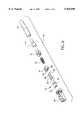
- FIG. 6is an exploded perspective view of the components of a fiber optic device incorporating the overmolded alignment ferrule of FIGS. 4-5 in the form of a plug received by a housing and adapted to mate with a similar fiber optic device;
- FIG. 7is a perspective view of the guide pin clip and guide pins of the fiber optic device of FIG. 6, illustrating one of the guide pins received by the guide pin clip and the other guide pin removed from the guide pin clip;
- FIG. 8is an assembled, cross-sectional view of the components of FIG. 6, also including a receptacle receiving the connector.
- An overmolded alignment ferrule 10 in accordance with a preferred embodiment of the inventioncomprises a precision portion in the form of an alignment block 12 and an overmolded body portion 14.
- the alignment block 12 illustrated in FIGS. 1-5is generally rectangular and has a generally flat front face 16, a generally flat rear face 18, a pair of generally flat side surfaces 20, and a pair of generally flat end surfaces 22.
- the alignment block 12may include one or more gripping members for gripping the overmolded body portion 14 to prevent displacement of the alignment block 12 relative to the overmolded body portion.
- the gripping membersare in the form of flanges 30 formed on the end surfaces 22 of the alignment block 12. Each of the illustrated flanges 30 is generally V-shaped.
- the illustrated alignment block 12defines a pair of guide pin channels 32 adapted to receive guide pins and a pair of fiber channels 34 for receiving optical fibers.
- the illustrated guide pin channels 32 and the fiber channels 34 of the alignment block 12are parallel to each other and extend the entire length of the alignment block.
- the alignment block 12may include chamfers 36 at the rear face of the alignment block 12 around each of the guide pin channels 32 to facilitate receipt of guide pins and around each of the fiber channels 34 to facilitate receipt of the optical fibers.
- Each of the guide pin channels 32 and fiber channels 34 of the alignment block 12has a center defined by its respective longitudinal axis.
- the guide pin channels 32 and the fiber channels 34may have any suitable predetermined locations and dimensions. In the illustrated embodiment, for example, the centers of the guide pin channels 32 and the fiber channels 34 of the alignment block 12 are all substantially aligned in a co-linear manner.
- the nominal spacing between the centers of the two fiber channels 34 of the illustrated alignment block 12is desirably 750 microns, and the nominal spacing between the centers of the two guide pin channels 32 of the alignment block is desirably 2600 microns. Additionally, the nominal spacing between one of the guide pin channels 32 and an adjacent fiber channel 34 of the alignment block 12 is 925 microns, and is substantially the same as the nominal spacing between the other guide pin channel of the alignment block and its adjacent fiber channel.
- the nominal diameters of each of the guide pin channels 32 and fiber hole channels 34 of the alignment block 12desirably are 700 microns and 125 microns, respectively.
- the nominal length of the front and rear faces 16 and 18 of the alignment block 12may be 3700 microns; the nominal length of the end surfaces 22 may be about 2500 microns; and the nominal width of the front and rear faces may be about 1600 microns.
- the alignment block 12may define additional fiber channels 34.
- the alignment block 12may define four, six, eight, ten or more fiber channels 34, which desirably have centers that are co-linear with each other and with the centers of one or more guide pin channels 32.
- the desired number of fiber channels 34 and the relative spacing and dimensions of the fiber and guide pin channels of the various alternative embodimentsmay depend upon the application of the invention.
- the centers of the guide pin channels 32 of the alignment block 12do not need to be co-linear with the centers of the two or more fiber channels 34 of the alignment block.
- the alignment block 12may include some fiber channels 34 that are not co-linear with respect to all of the other fiber channels.
- the alignment block 12may define two or more rows of fiber channels, with the guide pin channels of the alignment block used as the datum for defining the two or more rows.
- neither row of fiber channels of the alignment blockis co-linear with the guide pin channels, and the line between the first guide pin channels may be used as the basis for determining the "north-south" positioning of each row relative to the line.
- the overmolded body portion 14may have any suitable configuration depending on the configuration of the fiber optic connector.
- the illustrated overmolded body portion 14, for example,is configured to be incorporated in the fiber optic device illustrated in FIGS. 6 and 8 which is in the form of a plug 40 adapted to mate with a receptacle 58 and a similar plug 40.
- the overmolded body portion 14has a generally T-shaped configuration including a front face 42 and a rear face 44, and defines a bore 46 for receiving the alignment block 12.
- the overmolded body portion 14also defines a pair of guide pin channels 52 in communication with the guide pin channels 32 of the alignment block 12, and a pair of fiber channels 54 in communication with the fiber channels 34 of the alignment block 12.
- the rear face 44 of the overmolded body portion 14has chamfers 56 around each of its guide pin channels 52 to facilitate receipt of guide pins and around each of its fiber channels 54 to facilitate receipt of the optical fibers.
- the guide pin channels 52 and fiber channels 54 of the overmolded body portion 14are parallel to each other, and each also has a center defined by its longitudinal axis, all of which are substantially aligned in a co-linear manner.
- the diameters and the spacing between the centers of the various channels 52 and 54 of the overmolded body portion 14are substantially the same as the diameters and the spacing between the centers of the various channels 32 and 34 of the alignment block 12, except that less precision is required.
- the nominal length of the rear face 44 of the overmolded body portionmay be about 5000 microns and the nominal length of the front face of the overmolded body portion may be about 4350 microns.
- the nominal length of the overmolded body portion 14may be about 7700 microns.
- the guide pinsare preferably received within the first and second guide pin channels 32 and 52 for mating with an other fiber optic connector.
- the guide pinsmay be secured or positioned relative to the overmolded alignment ferrule by a guide pin clip or in any suitable manner.
- the female overmolded alignment ferrule 10is configured in any suitable manner to receive and engage guide pins of the male overmolded alignment ferrule 10.
- the optical fiberspreferably include a buffer coated portion, and a bare portion received within the first and second fiber channels 34 and 54.
- the overmolded alignment ferrule 10 in accordance with the present inventioncan be produced in any suitable manner.
- the alignment block 12 of the overmolded alignment ferrule 10is first produced and then the overmolded body portion 14 is produced by overmolding upon the alignment block 12.
- the alignment block 12desirably is produced by conventional molding process.
- its guide pin channels 32are used as datum to determine the positioning of its fiber channels 34 and the required positioning of its guide pin channels and its fiber channels is maintained by exacting tooling dimensions and short tooling component length.
- the alignment block 12After the alignment block 12 is produced, it is positioned and clamped for the overmolding process in which the overmolded body portion 14 is formed by encapsulating the alignment block.
- This processcan be accomplished in any suitable manner, such as, for example, conventional thermoplastic injection molding. This process combines the functional positioning of the alignment block 12 with the geometrical requirements for use in the fiber optic connector system.
- the guide pin channels 32 and the first fiber channels 34 of the alignment block 12should be sealed from the overmolding encapsulating compound in any suitable manner.
- a diametrical interferencemay be provided between the guide pin molding core and the guide pin channels 32, and a pin having a small conical taper can be used to seal the fiber channels 34 from the encapsulating compound.
- the alignment block 12desirably is made of a material that melts at a temperature above the application temperature of the encapsulating compound or a material that is not influenced by the encapsulating material temperature such as, for example, metal, ceramic, or thermoset composite material.
- the illustrated overmolded alignment ferrule 10is adapted to be incorporated within the plug 40 of FIGS. 6 and 8, which may be used to hold a conventional fiber optic cable and to mate with the receptacle 58 and a similar plug or any other suitable fiber optic device.
- the illustrated plug 40is received by the receptacle 58 and includes the connector 60, the overmolded alignment ferrule 10, guide pins 62, a U-shaped guide pin clip 64 for securing the guide pins 62 relative to the overmolded body portion 14, a coiled spring 70, a spring push member 72, a crimpable eyelet 74 and a strain relief boot 76.
- the overmolded alignment ferrule 10 and the guide pin clip 64are mounted within a forward end of the connector 60.
- the coiled spring 70is mounted within the connector 60 and between the spring push member 72 and the guide pin clip 64.
- the crimpable eyelet 74is mounted on the spring push member 72 and finally, the strain relief boot 76 is connected to the crimp
- each guide pin 62may comprise any suitable structure and may engage the guide pin clip 64 in any suitable manner.
- each guide pin 62includes a reduced diameter or neck portion 80 and the guide pin clip 64 defines a pair of bores 82, with each bore being generally rectangular and including an open side portion 84 and an open front portion 86.
- the open front portions 86 of the bores 82are key shaped so that the neck portions 80 of the guide pins 62 can be received within the open front portions and so that the guide pin clips 62 can engage the guide pins 62 within the open front portions by snap fit.
- the ends 90 of the illustrated guide pins 62are chamfered. (See FIGS. 6-8).
- the plug 40 illustrated in FIGS. 6 and 8is an example of a connector in which the ferrule according to the terms of the present invention can be incorporated.
- Other known connectors and connectors not known that make use of an MT or Mini-MT style ferrulemay also benefit from use of this ferrule according to the terms of the present invention as a replacement ferrule.
- few, if any, modifications to the connectorare necessary to make use of the ferrule according to the terms of the present invention.
- the present inventionenables the production of the alignment block 12 whereby the precision positioning of its fiber channel 34 may be accomplished without reliance upon external datum of the alignment block. Instead, with the present invention, the precise positioning may be based upon the location, number and dimensions of its guide pin channels 32. As a result, the alignment block 12 can be produced with a minimum amount of material, and the channels 32 and 34 of the alignment block 12 can be defined with relatively short tooling core pins.
Landscapes
- Physics & Mathematics (AREA)
- General Physics & Mathematics (AREA)
- Optics & Photonics (AREA)
- Mechanical Coupling Of Light Guides (AREA)
Abstract
Description
Claims (27)
Priority Applications (1)
| Application Number | Priority Date | Filing Date | Title |
|---|---|---|---|
| US09/014,209US5926596A (en) | 1998-01-28 | 1998-01-28 | Overmolded alignment ferrule |
Applications Claiming Priority (1)
| Application Number | Priority Date | Filing Date | Title |
|---|---|---|---|
| US09/014,209US5926596A (en) | 1998-01-28 | 1998-01-28 | Overmolded alignment ferrule |
Publications (1)
| Publication Number | Publication Date |
|---|---|
| US5926596Atrue US5926596A (en) | 1999-07-20 |
Family
ID=21764130
Family Applications (1)
| Application Number | Title | Priority Date | Filing Date |
|---|---|---|---|
| US09/014,209Expired - LifetimeUS5926596A (en) | 1998-01-28 | 1998-01-28 | Overmolded alignment ferrule |
Country Status (1)
| Country | Link |
|---|---|
| US (1) | US5926596A (en) |
Cited By (48)
| Publication number | Priority date | Publication date | Assignee | Title |
|---|---|---|---|---|
| US6290527B1 (en)* | 1998-07-03 | 2001-09-18 | Nippon Telegraph And Telephone Corp. | Nippon telegraph and telephone corporation |
| US6454464B1 (en)* | 1998-12-28 | 2002-09-24 | Computer Crafts, Inc. | Fiber optic connectors and transceiver test devices |
| US6464408B1 (en) | 1998-12-28 | 2002-10-15 | Computer Crafts, Inc. | Fiber optic connectors |
| US20030002801A1 (en)* | 2001-06-22 | 2003-01-02 | Bookham Technology Plc | System |
| US6572276B1 (en)* | 2000-11-21 | 2003-06-03 | Euromicron Werkezeuge Gmbh | Plug for fiber optic cables with a plug housing |
| US6669377B2 (en) | 2001-06-11 | 2003-12-30 | Corning Cable Systems Llc | Fiber optic connector and an associated pin retainer |
| US6761489B1 (en)* | 1999-12-14 | 2004-07-13 | Corning Cable Systems Llc | Ferrule having first and second body portions with different nominal widths and an associated mold and fabrication method |
| US20050036742A1 (en)* | 2003-08-29 | 2005-02-17 | Dean David L. | Molded fiber optic ferrule with integrally formed geometry features |
| US20050215101A1 (en)* | 2004-03-29 | 2005-09-29 | Pepe Paul J | Sealed electrical connector having internal latching mechanism therefore |
| US20070098328A1 (en)* | 2003-08-29 | 2007-05-03 | Dean David L Jr | Molded ferrule with reference surface for end face geometry measurement |
| US20080273837A1 (en)* | 2007-05-04 | 2008-11-06 | Mark Margolin | Super miniature, single fiber optical interconnect system with parallel slider push-push type insertion/withdrawal mechanism and method for using same |
| US20090046981A1 (en)* | 2007-08-13 | 2009-02-19 | Illum Technologies, Inc. | High density fiber optic interconnect system with push-release mechanism and method for using same |
| WO2011130441A1 (en)* | 2010-04-13 | 2011-10-20 | Commscope, Inc. Of North Carolina | Gender-neutral mpo connectors |
| US20130195406A1 (en)* | 2012-01-30 | 2013-08-01 | Terry L. Cooke | Overmolded ferrule boot and methods for making the same |
| US20130296799A1 (en)* | 2007-10-02 | 2013-11-07 | Medimop Medical Projects Ltd. | Key for securing components of a drug delivery system during assembly and/or transport and methods of using same |
| US9656019B2 (en) | 2007-10-02 | 2017-05-23 | Medimop Medical Projects Ltd. | Apparatuses for securing components of a drug delivery system during transport and methods of using same |
| US9782545B2 (en) | 2007-10-02 | 2017-10-10 | Medimop Medical Projects Ltd. | External drug pump |
| US9784925B2 (en) | 2015-03-16 | 2017-10-10 | Commscope, Inc. Of North Carolina | Tunable MPO connector |
| US9987432B2 (en) | 2015-09-22 | 2018-06-05 | West Pharma. Services IL, Ltd. | Rotation resistant friction adapter for plunger driver of drug delivery device |
| US10086145B2 (en) | 2015-09-22 | 2018-10-02 | West Pharma Services Il, Ltd. | Rotation resistant friction adapter for plunger driver of drug delivery device |
| US10149943B2 (en) | 2015-05-29 | 2018-12-11 | West Pharma. Services IL, Ltd. | Linear rotation stabilizer for a telescoping syringe stopper driverdriving assembly |
| US10376647B2 (en) | 2016-03-18 | 2019-08-13 | West Pharma. Services IL, Ltd. | Anti-rotation mechanism for telescopic screw assembly |
| US11187859B2 (en) | 2017-06-28 | 2021-11-30 | Corning Research & Development Corporation | Fiber optic connectors and methods of making the same |
| US11215768B2 (en) | 2017-06-28 | 2022-01-04 | Corning Research & Development Corporation | Fiber optic connectors and connectorization employing adhesive admitting adapters |
| US11294133B2 (en) | 2019-07-31 | 2022-04-05 | Corning Research & Development Corporation | Fiber optic networks using multiports and cable assemblies with cable-to-connector orientation |
| US11300746B2 (en) | 2017-06-28 | 2022-04-12 | Corning Research & Development Corporation | Fiber optic port module inserts, assemblies and methods of making the same |
| US11311674B2 (en) | 2016-01-21 | 2022-04-26 | West Pharma. Services IL, Ltd. | Medicament delivery device comprising a visual indicator |
| US11318254B2 (en) | 2015-10-09 | 2022-05-03 | West Pharma. Services IL, Ltd. | Injector needle cap remover |
| US11338090B2 (en) | 2016-08-01 | 2022-05-24 | West Pharma. Services IL, Ltd. | Anti-rotation cartridge pin |
| US11364337B2 (en) | 2016-01-21 | 2022-06-21 | West Pharma. Services IL, Ltd. | Force containment in an automatic injector |
| US11389597B2 (en) | 2016-03-16 | 2022-07-19 | West Pharma. Services IL, Ltd. | Staged telescopic screw assembly having different visual indicators |
| US11547802B2 (en) | 2015-10-09 | 2023-01-10 | West Pharma. Services IL, Ltd. | Angled syringe patch injector |
| US11604320B2 (en) | 2020-09-30 | 2023-03-14 | Corning Research & Development Corporation | Connector assemblies for telecommunication enclosures |
| US11650388B2 (en) | 2019-11-14 | 2023-05-16 | Corning Research & Development Corporation | Fiber optic networks having a self-supporting optical terminal and methods of installing the optical terminal |
| US11668890B2 (en) | 2017-06-28 | 2023-06-06 | Corning Research & Development Corporation | Multiports and other devices having optical connection ports with securing features and methods of making the same |
| US11672904B2 (en) | 2016-01-21 | 2023-06-13 | West Pharma. Services IL, Ltd. | Needle insertion and retraction mechanism |
| US11686913B2 (en) | 2020-11-30 | 2023-06-27 | Corning Research & Development Corporation | Fiber optic cable assemblies and connector assemblies having a crimp ring and crimp body and methods of fabricating the same |
| US11703646B2 (en) | 2017-06-28 | 2023-07-18 | Corning Research & Development Corporation | Multiports and optical connectors with rotationally discrete locking and keying features |
| US11819666B2 (en) | 2017-05-30 | 2023-11-21 | West Pharma. Services IL, Ltd. | Modular drive train for wearable injector |
| US11880076B2 (en) | 2020-11-30 | 2024-01-23 | Corning Research & Development Corporation | Fiber optic adapter assemblies including a conversion housing and a release housing |
| US11886010B2 (en) | 2019-10-07 | 2024-01-30 | Corning Research & Development Corporation | Fiber optic terminals and fiber optic networks having variable ratio couplers |
| US11927810B2 (en) | 2020-11-30 | 2024-03-12 | Corning Research & Development Corporation | Fiber optic adapter assemblies including a conversion housing and a release member |
| US11947167B2 (en) | 2021-05-26 | 2024-04-02 | Corning Research & Development Corporation | Fiber optic terminals and tools and methods for adjusting a split ratio of a fiber optic terminal |
| US11994722B2 (en) | 2020-11-30 | 2024-05-28 | Corning Research & Development Corporation | Fiber optic adapter assemblies including an adapter housing and a locking housing |
| US12019279B2 (en) | 2019-05-31 | 2024-06-25 | Corning Research & Development Corporation | Multiports and other devices having optical connection ports with sliding actuators and methods of making the same |
| US12271040B2 (en) | 2017-06-28 | 2025-04-08 | Corning Research & Development Corporation | Fiber optic extender ports, assemblies and methods of making the same |
| US12357767B2 (en) | 2016-08-01 | 2025-07-15 | West Pharma. Services IL, Ltd. | Partial door closure prevention spring |
| US12372727B2 (en) | 2020-10-30 | 2025-07-29 | Corning Research & Development Corporation | Female fiber optic connectors having a rocker latch arm and methods of making the same |
Citations (7)
| Publication number | Priority date | Publication date | Assignee | Title |
|---|---|---|---|---|
| US4759599A (en)* | 1985-12-24 | 1988-07-26 | Kabushiki Kaisha Toshiba | Optical connector |
| US5044720A (en)* | 1990-12-10 | 1991-09-03 | Amp Incorporated | Active device mount with mark prevention and method of making same |
| US5093878A (en)* | 1990-12-10 | 1992-03-03 | Amp Incorporated | Active device mount with mark prevention, anti-rotation features and method of making same |
| US5287426A (en)* | 1993-02-22 | 1994-02-15 | At&T Bell Laboratories | Methods for making optical fiber connectors |
| US5375183A (en)* | 1993-05-25 | 1994-12-20 | The Whitaker Corporation | Overmolded alignment ferrule |
| US5604830A (en)* | 1994-12-22 | 1997-02-18 | Hoechst Celanese Corp. | Multiple fiber connector for injection molded multiple fiberoptic coupler unit and cladding for same |
| US5685727A (en)* | 1995-01-20 | 1997-11-11 | Ocean Design, Inc. | Underwater mateable connector |
- 1998
- 1998-01-28USUS09/014,209patent/US5926596A/ennot_activeExpired - Lifetime
Patent Citations (7)
| Publication number | Priority date | Publication date | Assignee | Title |
|---|---|---|---|---|
| US4759599A (en)* | 1985-12-24 | 1988-07-26 | Kabushiki Kaisha Toshiba | Optical connector |
| US5044720A (en)* | 1990-12-10 | 1991-09-03 | Amp Incorporated | Active device mount with mark prevention and method of making same |
| US5093878A (en)* | 1990-12-10 | 1992-03-03 | Amp Incorporated | Active device mount with mark prevention, anti-rotation features and method of making same |
| US5287426A (en)* | 1993-02-22 | 1994-02-15 | At&T Bell Laboratories | Methods for making optical fiber connectors |
| US5375183A (en)* | 1993-05-25 | 1994-12-20 | The Whitaker Corporation | Overmolded alignment ferrule |
| US5604830A (en)* | 1994-12-22 | 1997-02-18 | Hoechst Celanese Corp. | Multiple fiber connector for injection molded multiple fiberoptic coupler unit and cladding for same |
| US5685727A (en)* | 1995-01-20 | 1997-11-11 | Ocean Design, Inc. | Underwater mateable connector |
Cited By (111)
| Publication number | Priority date | Publication date | Assignee | Title |
|---|---|---|---|---|
| US6290527B1 (en)* | 1998-07-03 | 2001-09-18 | Nippon Telegraph And Telephone Corp. | Nippon telegraph and telephone corporation |
| US6454464B1 (en)* | 1998-12-28 | 2002-09-24 | Computer Crafts, Inc. | Fiber optic connectors and transceiver test devices |
| US6464408B1 (en) | 1998-12-28 | 2002-10-15 | Computer Crafts, Inc. | Fiber optic connectors |
| US6554487B2 (en) | 1998-12-28 | 2003-04-29 | Computer Crafts, Inc. | Fiber optic connectors |
| US6761489B1 (en)* | 1999-12-14 | 2004-07-13 | Corning Cable Systems Llc | Ferrule having first and second body portions with different nominal widths and an associated mold and fabrication method |
| US6572276B1 (en)* | 2000-11-21 | 2003-06-03 | Euromicron Werkezeuge Gmbh | Plug for fiber optic cables with a plug housing |
| US6669377B2 (en) | 2001-06-11 | 2003-12-30 | Corning Cable Systems Llc | Fiber optic connector and an associated pin retainer |
| US6893162B2 (en)* | 2001-06-22 | 2005-05-17 | Bookham Technology Plc | System |
| US20030002801A1 (en)* | 2001-06-22 | 2003-01-02 | Bookham Technology Plc | System |
| US20050036742A1 (en)* | 2003-08-29 | 2005-02-17 | Dean David L. | Molded fiber optic ferrule with integrally formed geometry features |
| US20070098328A1 (en)* | 2003-08-29 | 2007-05-03 | Dean David L Jr | Molded ferrule with reference surface for end face geometry measurement |
| US7393142B2 (en) | 2003-08-29 | 2008-07-01 | Corning Cable Systems Llc | Molded ferrule with reference surface for end face geometry measurement |
| US20050215101A1 (en)* | 2004-03-29 | 2005-09-29 | Pepe Paul J | Sealed electrical connector having internal latching mechanism therefore |
| US7074066B2 (en) | 2004-03-29 | 2006-07-11 | Tyco Electronics Corporation | Sealed electrical connector having internal latching mechanism therefore |
| US20080273837A1 (en)* | 2007-05-04 | 2008-11-06 | Mark Margolin | Super miniature, single fiber optical interconnect system with parallel slider push-push type insertion/withdrawal mechanism and method for using same |
| US7806599B2 (en) | 2007-05-04 | 2010-10-05 | Illum Technologies, Inc. | Super miniature, single fiber optical interconnect system with parallel slider push-push type insertion/withdrawal mechanism and method for using same |
| US20090046981A1 (en)* | 2007-08-13 | 2009-02-19 | Illum Technologies, Inc. | High density fiber optic interconnect system with push-release mechanism and method for using same |
| US7717625B2 (en) | 2007-08-13 | 2010-05-18 | Illum Technologies, Inc. | High density fiber optic interconnect system with push-release mechanism and method for using same |
| US11504481B2 (en) | 2007-10-02 | 2022-11-22 | West Pharma. Services IL, Ltd. | Anti-rotation feature for infusion pump cartridge |
| US10960131B2 (en) | 2007-10-02 | 2021-03-30 | West Pharma. Services IL, Ltd. | Apparatuses for securing components of a drug delivery system during transport and methods of using same |
| US20130296799A1 (en)* | 2007-10-02 | 2013-11-07 | Medimop Medical Projects Ltd. | Key for securing components of a drug delivery system during assembly and/or transport and methods of using same |
| US10716890B2 (en)* | 2007-10-02 | 2020-07-21 | West Pharma. Services IL, Ltd. | Method of using a key to secure components of a drug delivery system during assembly |
| US20170112998A1 (en)* | 2007-10-02 | 2017-04-27 | Medimop Medical Projects Ltd. | Method of using a key to secure components of a drug delivery system during assembly |
| US9656019B2 (en) | 2007-10-02 | 2017-05-23 | Medimop Medical Projects Ltd. | Apparatuses for securing components of a drug delivery system during transport and methods of using same |
| US9782545B2 (en) | 2007-10-02 | 2017-10-10 | Medimop Medical Projects Ltd. | External drug pump |
| US10420880B2 (en)* | 2007-10-02 | 2019-09-24 | West Pharma. Services IL, Ltd. | Key for securing components of a drug delivery system during assembly and/or transport and methods of using same |
| US9861759B2 (en) | 2007-10-02 | 2018-01-09 | Medimop Medical Projects Ltd. | External drug pump |
| US10413679B2 (en) | 2007-10-02 | 2019-09-17 | West Pharma. Services IL, Ltd. | External drug pump |
| US11590291B2 (en) | 2007-10-02 | 2023-02-28 | West Pharma. Services IL, Ltd. | External drug pump |
| US10384017B2 (en) | 2007-10-02 | 2019-08-20 | West Pharma. Services IL, Ltd. | Anti-rotation feature for infusion pump cartridge |
| US10350365B2 (en) | 2007-10-02 | 2019-07-16 | West Pharma. Services IL, Ltd. | External drug pump |
| WO2011130441A1 (en)* | 2010-04-13 | 2011-10-20 | Commscope, Inc. Of North Carolina | Gender-neutral mpo connectors |
| US20130195406A1 (en)* | 2012-01-30 | 2013-08-01 | Terry L. Cooke | Overmolded ferrule boot and methods for making the same |
| US8678668B2 (en)* | 2012-01-30 | 2014-03-25 | Corning Cable Systems Llc | Overmolded ferrule boot and methods for making the same |
| US9784925B2 (en) | 2015-03-16 | 2017-10-10 | Commscope, Inc. Of North Carolina | Tunable MPO connector |
| US10149943B2 (en) | 2015-05-29 | 2018-12-11 | West Pharma. Services IL, Ltd. | Linear rotation stabilizer for a telescoping syringe stopper driverdriving assembly |
| US10758679B2 (en) | 2015-05-29 | 2020-09-01 | West Pharma. Services IL, Ltd. | Linear rotation stabilizer for a telescoping syringe stopper driverdriving assembly |
| US9987432B2 (en) | 2015-09-22 | 2018-06-05 | West Pharma. Services IL, Ltd. | Rotation resistant friction adapter for plunger driver of drug delivery device |
| US10912891B2 (en) | 2015-09-22 | 2021-02-09 | West Pharma. Services IL, Ltd. | Rotation resistant friction adapter for plunger driver of drug delivery device |
| US10086145B2 (en) | 2015-09-22 | 2018-10-02 | West Pharma Services Il, Ltd. | Rotation resistant friction adapter for plunger driver of drug delivery device |
| US11759573B2 (en) | 2015-10-09 | 2023-09-19 | West Pharma. Services, IL, Ltd. | Bent fluid path add on to a prefilled reservoir |
| US12138429B2 (en) | 2015-10-09 | 2024-11-12 | West Pharma. Services IL, Ltd. | Angled syringe patch injector |
| US12036394B2 (en) | 2015-10-09 | 2024-07-16 | West Pharma. Services IL, Ltd. | Injector needle cap and/or liner remover |
| US11547802B2 (en) | 2015-10-09 | 2023-01-10 | West Pharma. Services IL, Ltd. | Angled syringe patch injector |
| US11724034B2 (en) | 2015-10-09 | 2023-08-15 | West Pharma. Services, IL, Ltd. | Injector system |
| US11318254B2 (en) | 2015-10-09 | 2022-05-03 | West Pharma. Services IL, Ltd. | Injector needle cap remover |
| US12208246B2 (en) | 2015-10-09 | 2025-01-28 | West Pharma. Services IL, Ltd. | Bent fluid path add on to a prefilled fluid reservoir |
| US11364337B2 (en) | 2016-01-21 | 2022-06-21 | West Pharma. Services IL, Ltd. | Force containment in an automatic injector |
| US12005237B2 (en) | 2016-01-21 | 2024-06-11 | West Pharma. Services IL, Ltd. | Medicament delivery device comprising a visual indicator |
| US12427261B2 (en) | 2016-01-21 | 2025-09-30 | West Pharma. Services IL, Ltd. | Medicament delivery device comprising a visual indicator |
| US11311674B2 (en) | 2016-01-21 | 2022-04-26 | West Pharma. Services IL, Ltd. | Medicament delivery device comprising a visual indicator |
| US11672904B2 (en) | 2016-01-21 | 2023-06-13 | West Pharma. Services IL, Ltd. | Needle insertion and retraction mechanism |
| US11389597B2 (en) | 2016-03-16 | 2022-07-19 | West Pharma. Services IL, Ltd. | Staged telescopic screw assembly having different visual indicators |
| US10376647B2 (en) | 2016-03-18 | 2019-08-13 | West Pharma. Services IL, Ltd. | Anti-rotation mechanism for telescopic screw assembly |
| US11338090B2 (en) | 2016-08-01 | 2022-05-24 | West Pharma. Services IL, Ltd. | Anti-rotation cartridge pin |
| US12357767B2 (en) | 2016-08-01 | 2025-07-15 | West Pharma. Services IL, Ltd. | Partial door closure prevention spring |
| US11819666B2 (en) | 2017-05-30 | 2023-11-21 | West Pharma. Services IL, Ltd. | Modular drive train for wearable injector |
| US11409055B2 (en) | 2017-06-28 | 2022-08-09 | Corning Optical Communications LLC | Multiports having connection ports with associated securing features and methods of making the same |
| US11914198B2 (en) | 2017-06-28 | 2024-02-27 | Corning Research & Development Corporation | Compact fiber optic connectors having multiple connector footprints, along with cable assemblies and methods of making the same |
| US11493700B2 (en) | 2017-06-28 | 2022-11-08 | Corning Research & Development Corporation | Compact fiber optic connectors, cable assemblies and methods of making the same |
| US11487065B2 (en) | 2017-06-28 | 2022-11-01 | Corning Research & Development Corporation | Multiports and devices having a connector port with a rotating securing feature |
| US11531168B2 (en) | 2017-06-28 | 2022-12-20 | Corning Research & Development Corporation | Fiber optic connectors having a keying structure and methods of making the same |
| US11536913B2 (en) | 2017-06-28 | 2022-12-27 | Corning Research & Development Corporation | Fiber optic connectors and connectorization employing adhesive admitting adapters |
| US11543600B2 (en) | 2017-06-28 | 2023-01-03 | Corning Research & Development Corporation | Compact fiber optic connectors having multiple connector footprints, along with cable assemblies and methods of making the same |
| US11460646B2 (en) | 2017-06-28 | 2022-10-04 | Corning Research & Development Corporation | Fiber optic connectors and multiport assemblies including retention features |
| US11579377B2 (en) | 2017-06-28 | 2023-02-14 | Corning Research & Development Corporation | Compact fiber optic connectors, cable assemblies and methods of making the same with alignment elements |
| US11415759B2 (en) | 2017-06-28 | 2022-08-16 | Corning Optical Communications LLC | Multiports having a connection port insert and methods of making the same |
| US11624877B2 (en) | 2017-06-28 | 2023-04-11 | Corning Research & Development Corporation | Multiports having connection ports with securing features that actuate flexures and methods of making the same |
| US11656414B2 (en) | 2017-06-28 | 2023-05-23 | Corning Research & Development Corporation | Multiports and other devices having connection ports with securing features and methods of making the same |
| US11668890B2 (en) | 2017-06-28 | 2023-06-06 | Corning Research & Development Corporation | Multiports and other devices having optical connection ports with securing features and methods of making the same |
| US11327247B2 (en) | 2017-06-28 | 2022-05-10 | Corning Optical Communications LLC | Multiports having connection ports formed in the shell and associated securing features |
| US11703646B2 (en) | 2017-06-28 | 2023-07-18 | Corning Research & Development Corporation | Multiports and optical connectors with rotationally discrete locking and keying features |
| US11307364B2 (en) | 2017-06-28 | 2022-04-19 | Corning Research & Development Corporation | Compact fiber optic connectors having multiple connector footprints, along with cable assemblies and methods of making the same |
| US11300746B2 (en) | 2017-06-28 | 2022-04-12 | Corning Research & Development Corporation | Fiber optic port module inserts, assemblies and methods of making the same |
| US11789214B2 (en) | 2017-06-28 | 2023-10-17 | Corning Research & Development Corporation | Multiports and other devices having keyed connection ports and securing features and methods of making the same |
| US11300735B2 (en) | 2017-06-28 | 2022-04-12 | Corning Research & Development Corporation | Compact fiber optic connectors having multiple connector footprints, along with cable assemblies and methods of making the same |
| US12429655B2 (en) | 2017-06-28 | 2025-09-30 | Corning Optical Communications LLC | Multiports having connection ports with associated securing features and methods of making the same |
| US11187859B2 (en) | 2017-06-28 | 2021-11-30 | Corning Research & Development Corporation | Fiber optic connectors and methods of making the same |
| US12379551B2 (en) | 2017-06-28 | 2025-08-05 | Corning Optical Communications LLC | Multiports having connection ports formed in the shell and associated securing features |
| US12379552B2 (en) | 2017-06-28 | 2025-08-05 | Corning Research & Development Corporation | Compact fiber optic connectors, cable assemblies and methods of making the same |
| US11886017B2 (en) | 2017-06-28 | 2024-01-30 | Corning Research & Development Corporation | Multiports and other devices having connection ports with securing features and methods of making the same |
| US11215768B2 (en) | 2017-06-28 | 2022-01-04 | Corning Research & Development Corporation | Fiber optic connectors and connectorization employing adhesive admitting adapters |
| US11906792B2 (en) | 2017-06-28 | 2024-02-20 | Corning Research & Development Corporation | Compact fiber optic connectors having multiple connector footprints, along with cable assemblies and methods of making the same |
| US11914197B2 (en) | 2017-06-28 | 2024-02-27 | Corning Research & Development Corporation | Compact fiber optic connectors having multiple connector footprints, along with cable assemblies and methods of making the same |
| US11493699B2 (en) | 2017-06-28 | 2022-11-08 | Corning Research & Development Corporation | Multifiber fiber optic connectors, cable assemblies and methods of making the same |
| US12353024B2 (en) | 2017-06-28 | 2025-07-08 | Corning Research & Development Corporation | Multiports and optical connectors with rotationally discrete locking and keying features |
| US11940656B2 (en) | 2017-06-28 | 2024-03-26 | Corning Research & Development Corporation | Compact fiber optic connectors, cable assemblies and methods of making the same |
| US12353025B2 (en) | 2017-06-28 | 2025-07-08 | Corning Optical Communications LLC | Multiports having a connection port insert and methods of making the same |
| US11966089B2 (en) | 2017-06-28 | 2024-04-23 | Corning Optical Communications, Llc | Multiports having connection ports formed in the shell and associated securing features |
| US12298568B2 (en) | 2017-06-28 | 2025-05-13 | Corning Research & Development Corporation | Fiber optic connectors and multiport assemblies including retention features |
| US12276846B2 (en) | 2017-06-28 | 2025-04-15 | Corning Research & Development Corporation | Compact fiber optic connectors, cable assemblies and methods of making the same |
| US12013578B2 (en) | 2017-06-28 | 2024-06-18 | Corning Research & Development Corporation | Multifiber fiber optic connectors, cable assemblies and methods of making the same |
| US12271040B2 (en) | 2017-06-28 | 2025-04-08 | Corning Research & Development Corporation | Fiber optic extender ports, assemblies and methods of making the same |
| US11262509B2 (en) | 2017-06-28 | 2022-03-01 | Corning Research & Development Corporation | Compact fiber optic connectors having multiple connector footprints, along with cable assemblies and methods of making the same |
| US11287582B2 (en) | 2017-06-28 | 2022-03-29 | Corning Research & Development Corporation | Compact fiber optic connectors, cable assemblies and methods of making the same |
| US12092878B2 (en) | 2017-06-28 | 2024-09-17 | Corning Research & Development Corporation | Fiber optic connectors having a keying structure and methods of making the same |
| US11287581B2 (en)* | 2017-06-28 | 2022-03-29 | Corning Research & Development Corporation | Compact fiber optic connectors, cable assemblies and methods of making the same |
| US12174432B2 (en) | 2017-06-28 | 2024-12-24 | Corning Research & Development Corporation | Fiber optic connectors and connectorization employing adhesive admitting adapters |
| US12019279B2 (en) | 2019-05-31 | 2024-06-25 | Corning Research & Development Corporation | Multiports and other devices having optical connection ports with sliding actuators and methods of making the same |
| US11294133B2 (en) | 2019-07-31 | 2022-04-05 | Corning Research & Development Corporation | Fiber optic networks using multiports and cable assemblies with cable-to-connector orientation |
| US11886010B2 (en) | 2019-10-07 | 2024-01-30 | Corning Research & Development Corporation | Fiber optic terminals and fiber optic networks having variable ratio couplers |
| US11650388B2 (en) | 2019-11-14 | 2023-05-16 | Corning Research & Development Corporation | Fiber optic networks having a self-supporting optical terminal and methods of installing the optical terminal |
| US12019285B2 (en) | 2020-09-30 | 2024-06-25 | Corning Research & Development Corporation | Connector assemblies for telecommunication enclosures |
| US11604320B2 (en) | 2020-09-30 | 2023-03-14 | Corning Research & Development Corporation | Connector assemblies for telecommunication enclosures |
| US12372727B2 (en) | 2020-10-30 | 2025-07-29 | Corning Research & Development Corporation | Female fiber optic connectors having a rocker latch arm and methods of making the same |
| US11927810B2 (en) | 2020-11-30 | 2024-03-12 | Corning Research & Development Corporation | Fiber optic adapter assemblies including a conversion housing and a release member |
| US11880076B2 (en) | 2020-11-30 | 2024-01-23 | Corning Research & Development Corporation | Fiber optic adapter assemblies including a conversion housing and a release housing |
| US11686913B2 (en) | 2020-11-30 | 2023-06-27 | Corning Research & Development Corporation | Fiber optic cable assemblies and connector assemblies having a crimp ring and crimp body and methods of fabricating the same |
| US12345927B2 (en) | 2020-11-30 | 2025-07-01 | Corning Research & Development Corporation | Fiber optic adapter assemblies including a conversion housing and a release housing |
| US11994722B2 (en) | 2020-11-30 | 2024-05-28 | Corning Research & Development Corporation | Fiber optic adapter assemblies including an adapter housing and a locking housing |
| US11947167B2 (en) | 2021-05-26 | 2024-04-02 | Corning Research & Development Corporation | Fiber optic terminals and tools and methods for adjusting a split ratio of a fiber optic terminal |
Similar Documents
| Publication | Publication Date | Title |
|---|---|---|
| US5926596A (en) | Overmolded alignment ferrule | |
| US4515434A (en) | Fiber optic connector | |
| US4715675A (en) | Fiber optic ferrule | |
| US4652082A (en) | Angled electro optic connector | |
| US4291943A (en) | Connector for optical fiber cables | |
| US4258977A (en) | Optical fibre connector | |
| US5231685A (en) | Multi-way electro-optic connector assemblies and optical fiber ferrule assemblies therefor | |
| EP0203611B1 (en) | Optical fiber connectors and methods of making | |
| US4090778A (en) | Terminating optical fibers and optical fiber connector | |
| US4225214A (en) | Connector construction | |
| US5390269A (en) | Fiber optic connector with high resolution tunable fiber holder | |
| US5923804A (en) | Fiber optic connector and an associated method of fabrication | |
| US4526438A (en) | Alignment sleeve for fiber optic connectors | |
| US20040152354A1 (en) | Pin retainer for fiber optic connector and associated fabrication method | |
| US4312564A (en) | Multi-fiber optic connector | |
| JPS6258209A (en) | Optical fiber connector | |
| US4752111A (en) | Fiber optic connector | |
| JPS619612A (en) | Method and apparatus for forming mold of fiber optic connector ferrule | |
| US5727101A (en) | Monolithic ferrule for receiving and positioning multiple optical fibers and an optical fiber connector incorporating same | |
| US5892871A (en) | Fiber optic cable termination | |
| GB2239104A (en) | Multi-way electro-optic connectors | |
| JPH03171018A (en) | Separable connector group for optical fiber | |
| JP2001505669A (en) | Optical fiber connector | |
| US6210047B1 (en) | Method of fabricating a fiber optic connector ferrule | |
| CA2348866A1 (en) | Optical connector using large diameter alignment features |
Legal Events
| Date | Code | Title | Description |
|---|---|---|---|
| AS | Assignment | Owner name:WHITAKER CORPORATION, THE, DELAWARE Free format text:ASSIGNMENT OF ASSIGNORS INTEREST;ASSIGNORS:EDWARDS, BRYAN THOMAS;MANSBERGER, ROBERT LEON, II;REEL/FRAME:008950/0121 Effective date:19980128 | |
| STCF | Information on status: patent grant | Free format text:PATENTED CASE | |
| FPAY | Fee payment | Year of fee payment:4 | |
| FPAY | Fee payment | Year of fee payment:8 | |
| FPAY | Fee payment | Year of fee payment:12 | |
| AS | Assignment | Owner name:THE WHITAKER LLC, DELAWARE Free format text:CERTIFICATE OF CONVERSION;ASSIGNOR:THE WHITAKER CORPORATION;REEL/FRAME:036068/0954 Effective date:20100805 | |
| AS | Assignment | Owner name:COMMSCOPE EMEA LIMITED, IRELAND Free format text:ASSIGNMENT OF ASSIGNORS INTEREST;ASSIGNOR:THE WHITAKER LLC;REEL/FRAME:036942/0001 Effective date:20150824 | |
| AS | Assignment | Owner name:COMMSCOPE TECHNOLOGIES LLC, NORTH CAROLINA Free format text:ASSIGNMENT OF ASSIGNORS INTEREST;ASSIGNOR:COMMSCOPE EMEA LIMITED;REEL/FRAME:037012/0001 Effective date:20150828 | |
| AS | Assignment | Owner name:JPMORGAN CHASE BANK, N.A., AS COLLATERAL AGENT, ILLINOIS Free format text:PATENT SECURITY AGREEMENT (TERM);ASSIGNOR:COMMSCOPE TECHNOLOGIES LLC;REEL/FRAME:037513/0709 Effective date:20151220 Owner name:JPMORGAN CHASE BANK, N.A., AS COLLATERAL AGENT, ILLINOIS Free format text:PATENT SECURITY AGREEMENT (ABL);ASSIGNOR:COMMSCOPE TECHNOLOGIES LLC;REEL/FRAME:037514/0196 Effective date:20151220 Owner name:JPMORGAN CHASE BANK, N.A., AS COLLATERAL AGENT, IL Free format text:PATENT SECURITY AGREEMENT (ABL);ASSIGNOR:COMMSCOPE TECHNOLOGIES LLC;REEL/FRAME:037514/0196 Effective date:20151220 Owner name:JPMORGAN CHASE BANK, N.A., AS COLLATERAL AGENT, IL Free format text:PATENT SECURITY AGREEMENT (TERM);ASSIGNOR:COMMSCOPE TECHNOLOGIES LLC;REEL/FRAME:037513/0709 Effective date:20151220 | |
| AS | Assignment | Owner name:COMMSCOPE TECHNOLOGIES LLC, NORTH CAROLINA Free format text:RELEASE BY SECURED PARTY;ASSIGNOR:JPMORGAN CHASE BANK, N.A.;REEL/FRAME:048840/0001 Effective date:20190404 Owner name:COMMSCOPE, INC. OF NORTH CAROLINA, NORTH CAROLINA Free format text:RELEASE BY SECURED PARTY;ASSIGNOR:JPMORGAN CHASE BANK, N.A.;REEL/FRAME:048840/0001 Effective date:20190404 Owner name:ALLEN TELECOM LLC, ILLINOIS Free format text:RELEASE BY SECURED PARTY;ASSIGNOR:JPMORGAN CHASE BANK, N.A.;REEL/FRAME:048840/0001 Effective date:20190404 Owner name:REDWOOD SYSTEMS, INC., NORTH CAROLINA Free format text:RELEASE BY SECURED PARTY;ASSIGNOR:JPMORGAN CHASE BANK, N.A.;REEL/FRAME:048840/0001 Effective date:20190404 Owner name:ANDREW LLC, NORTH CAROLINA Free format text:RELEASE BY SECURED PARTY;ASSIGNOR:JPMORGAN CHASE BANK, N.A.;REEL/FRAME:048840/0001 Effective date:20190404 Owner name:REDWOOD SYSTEMS, INC., NORTH CAROLINA Free format text:RELEASE BY SECURED PARTY;ASSIGNOR:JPMORGAN CHASE BANK, N.A.;REEL/FRAME:049260/0001 Effective date:20190404 Owner name:ANDREW LLC, NORTH CAROLINA Free format text:RELEASE BY SECURED PARTY;ASSIGNOR:JPMORGAN CHASE BANK, N.A.;REEL/FRAME:049260/0001 Effective date:20190404 Owner name:COMMSCOPE TECHNOLOGIES LLC, NORTH CAROLINA Free format text:RELEASE BY SECURED PARTY;ASSIGNOR:JPMORGAN CHASE BANK, N.A.;REEL/FRAME:049260/0001 Effective date:20190404 Owner name:ALLEN TELECOM LLC, ILLINOIS Free format text:RELEASE BY SECURED PARTY;ASSIGNOR:JPMORGAN CHASE BANK, N.A.;REEL/FRAME:049260/0001 Effective date:20190404 Owner name:COMMSCOPE, INC. OF NORTH CAROLINA, NORTH CAROLINA Free format text:RELEASE BY SECURED PARTY;ASSIGNOR:JPMORGAN CHASE BANK, N.A.;REEL/FRAME:049260/0001 Effective date:20190404 |