US5926357A - Aluminum electrolytic capacitor for implantable medical device - Google Patents
Aluminum electrolytic capacitor for implantable medical deviceDownload PDFInfo
- Publication number
- US5926357A US5926357AUS08/876,274US87627497AUS5926357AUS 5926357 AUS5926357 AUS 5926357AUS 87627497 AUS87627497 AUS 87627497AUS 5926357 AUS5926357 AUS 5926357A
- Authority
- US
- United States
- Prior art keywords
- housing
- feed
- capacitor
- aluminum
- post
- Prior art date
- Legal status (The legal status is an assumption and is not a legal conclusion. Google has not performed a legal analysis and makes no representation as to the accuracy of the status listed.)
- Expired - Lifetime
Links
- 239000003990capacitorSubstances0.000titleclaimsabstractdescription40
- XAGFODPZIPBFFR-UHFFFAOYSA-NaluminiumChemical compound[Al]XAGFODPZIPBFFR-UHFFFAOYSA-N0.000titleclaimsabstractdescription34
- 229910052782aluminiumInorganic materials0.000titleclaimsabstractdescription33
- 239000012530fluidSubstances0.000claimsabstractdescription8
- 239000004020conductorSubstances0.000claimsabstractdescription6
- 238000004891communicationMethods0.000claimsabstractdescription3
- 239000000463materialSubstances0.000claimsdescription6
- RYGMFSIKBFXOCR-UHFFFAOYSA-NCopperChemical compound[Cu]RYGMFSIKBFXOCR-UHFFFAOYSA-N0.000claimsdescription4
- 229910052790berylliumInorganic materials0.000claimsdescription4
- ATBAMAFKBVZNFJ-UHFFFAOYSA-Nberyllium atomChemical compound[Be]ATBAMAFKBVZNFJ-UHFFFAOYSA-N0.000claimsdescription4
- 229910052802copperInorganic materials0.000claimsdescription4
- 239000010949copperSubstances0.000claimsdescription4
- 239000012212insulatorSubstances0.000claimsdescription4
- 229940030602cardiac therapy drugDrugs0.000claimsdescription2
- 229910000881Cu alloyInorganic materials0.000claims5
- 238000009413insulationMethods0.000abstractdescription2
- 230000006835compressionEffects0.000description6
- 238000007906compressionMethods0.000description6
- 229910045601alloyInorganic materials0.000description4
- 239000000956alloySubstances0.000description4
- 239000003792electrolyteSubstances0.000description4
- 230000035939shockEffects0.000description3
- 238000010276constructionMethods0.000description2
- 239000008393encapsulating agentSubstances0.000description2
- 239000012535impuritySubstances0.000description2
- 238000000034methodMethods0.000description2
- 238000007747platingMethods0.000description2
- 238000003466weldingMethods0.000description2
- 229910000838Al alloyInorganic materials0.000description1
- 239000004593EpoxySubstances0.000description1
- 206010049447TachyarrhythmiaDiseases0.000description1
- 208000001871TachycardiaDiseases0.000description1
- ATJFFYVFTNAWJD-UHFFFAOYSA-NTinChemical compound[Sn]ATJFFYVFTNAWJD-UHFFFAOYSA-N0.000description1
- 238000009825accumulationMethods0.000description1
- 239000010405anode materialSubstances0.000description1
- 206010003119arrhythmiaDiseases0.000description1
- QVGXLLKOCUKJST-UHFFFAOYSA-Natomic oxygenChemical compound[O]QVGXLLKOCUKJST-UHFFFAOYSA-N0.000description1
- 239000011324beadSubstances0.000description1
- 230000000747cardiac effectEffects0.000description1
- 206010061592cardiac fibrillationDiseases0.000description1
- 238000013194cardioversionMethods0.000description1
- 239000000356contaminantSubstances0.000description1
- 238000002788crimpingMethods0.000description1
- 238000005520cutting processMethods0.000description1
- 238000001514detection methodMethods0.000description1
- 238000005530etchingMethods0.000description1
- 230000002600fibrillogenic effectEffects0.000description1
- 239000011888foilSubstances0.000description1
- 238000002513implantationMethods0.000description1
- 238000009434installationMethods0.000description1
- 239000000203mixtureSubstances0.000description1
- KERTUBUCQCSNJU-UHFFFAOYSA-Lnickel(2+);disulfamateChemical compound[Ni+2].NS([O-])(=O)=O.NS([O-])(=O)=OKERTUBUCQCSNJU-UHFFFAOYSA-L0.000description1
- TWNQGVIAIRXVLR-UHFFFAOYSA-Noxo(oxoalumanyloxy)alumaneChemical compoundO=[Al]O[Al]=OTWNQGVIAIRXVLR-UHFFFAOYSA-N0.000description1
- 229910052760oxygenInorganic materials0.000description1
- 239000001301oxygenSubstances0.000description1
- 230000035515penetrationEffects0.000description1
- 238000003825pressingMethods0.000description1
- 238000009877renderingMethods0.000description1
- 238000007789sealingMethods0.000description1
- 229910000679solderInorganic materials0.000description1
- 238000005476solderingMethods0.000description1
- 230000000638stimulationEffects0.000description1
- 238000003860storageMethods0.000description1
- 210000001321subclavian veinAnatomy0.000description1
- 238000002560therapeutic procedureMethods0.000description1
Images


Classifications
- H—ELECTRICITY
- H01—ELECTRIC ELEMENTS
- H01G—CAPACITORS; CAPACITORS, RECTIFIERS, DETECTORS, SWITCHING DEVICES, LIGHT-SENSITIVE OR TEMPERATURE-SENSITIVE DEVICES OF THE ELECTROLYTIC TYPE
- H01G9/00—Electrolytic capacitors, rectifiers, detectors, switching devices, light-sensitive or temperature-sensitive devices; Processes of their manufacture
- H01G9/004—Details
- H01G9/008—Terminals
- H—ELECTRICITY
- H01—ELECTRIC ELEMENTS
- H01G—CAPACITORS; CAPACITORS, RECTIFIERS, DETECTORS, SWITCHING DEVICES, LIGHT-SENSITIVE OR TEMPERATURE-SENSITIVE DEVICES OF THE ELECTROLYTIC TYPE
- H01G9/00—Electrolytic capacitors, rectifiers, detectors, switching devices, light-sensitive or temperature-sensitive devices; Processes of their manufacture
- H01G9/004—Details
- H01G9/08—Housing; Encapsulation
- H01G9/10—Sealing, e.g. of lead-in wires
Definitions
- This inventionrelates to electronic components for implantable medical devices, and more particularly to charge storage components for cardiac stimulation devices.
- Defibrillatorsare implanted in patients susceptible to cardiac arrhythmias or fibrillation. Such devices provide cardioversion or defibrillation by delivering a high voltage shock to the patient's heart, typically about 500-750V. High voltage capacitors are used in defibrillators to accumulate the high voltage charge following detection of a tachyarrhythmia. In the effort to make implantable devices as small and thin as possible, flat aluminum electrolytic capacitors are used.
- Flat capacitorsinclude a plurality of aluminum layers laminarly arranged in a stack. Each layer includes an anode and a cathode, with the anodes and cathodes being commonly connected to respective connectors.
- the layersmay be cut in nearly any shape, to fit within a similarly shaped aluminum housing designed for a particular application.
- the cathode layerspreferably are together connected to the housing, while the anodes are together connected to a feed-through post that tightly passes through a hole on the housing, but is electrically insulated from the housing.
- the feed-through postserves as an external connector for interfacing with other components.
- the disclosed embodimentprovides an aluminum electrolytic capacitor with an aluminum housing defining a chamber, and having a feed-through aperture providing communication with the chamber from outside of the housing.
- a number of aluminum anode layersare positioned within the chamber, and a feed-through member formed of a first conductive material occupies the feed-through aperture.
- the feed-through memberhas an inner end extending into the chamber, an outer end extending externally from the housing, and an insulative sleeve encompassing an intermediate portion of the feed-through member and directly contacting the housing at the feed-through aperture to prevent electrical contact between the feed-through member and the housing.
- a connection element formed of a second different conductive materialis attached to the inner end of feed-through member and spaced apart from the housing.
- a compressible insulative gasketmay be positioned between the housing and the connection element to provide insulation and a fluid seal.
- FIG. 1is a plan view of a cardiac therapy device according to a preferred embodiment of the invention.
- FIG. 2is a plan view of a capacitor according to the embodiment of FIG. 1.
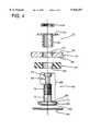
- FIG. 3is an enlarged sectional view of a portion of the capacitor of FIG. 2.
- FIG. 4is an exploded view of a portion of the capacitor of FIG. 2.
- FIG. 1illustrates a defibrillator 12 for pectoral implantation.
- a single pass endocardial lead set 14extends from the unit, through the patient's subclavian vein, and into the patient's heart.
- the defibrillator 12includes an outer housing 20 that includes a connector portion 21 for attachment of the lead set 14.
- the housing 20contains a transformer 22, a battery 24, control circuitry 26, and two capacitors 28 (only one shown.)
- the batteryprovides low voltage electrical energy to the transformer and its associated circuitry to charge the capacitors when needed so that they may provide a high voltage shock.
- the control circuitry 26connects to the lead set 14 so that it may sense and analyze electrical signals from the heart, and control the delivery of a an appropriate therapy such as a high voltage shock.
- FIG. 2illustrates in detail the construction of the capacitor 28, which may be designed as virtually any flat shape to conform to a desired housing shape.
- the capacitorincludes a metallic housing 32 defining a chamber 34, in which resides a capacitor stack 36.
- the housingincludes a lid (not shown) that is welded about the periphery to provide a hermetic seal to retain electrolyte fluid.
- the capacitor stack 36is formed of a number of essentially identical flat capacitor layers whose electrical elements are connected in parallel.
- the layersinclude alternating interleaved aluminum anode and cathode sheets.
- the sheetshave cutout regions 40 at their peripheries, with the cutouts of each layer being aligned when the sheets are installed in the housing to provide space for electrical connections.
- the anodesinclude anode tabs or plate extensions 42 extending into the cutout in registration with each other. These plate extensions are masked during etching so that they remain flexible and may easily be compressed together and joined at their free ends by welding. These free ends are simultaneously joined to a high purity 1199 aluminum ribbon 93 (see FIG. 3).
- a YAG laseris a suitable welder.
- the ribbonwill have been preattached to the head of an anode feed through assembly as will be discussed below.
- the cathodesinclude cathode tabs 44 that extend into the cutout region and are registered with each other, but spaced apart from the anode tabs to allow separate connection without shorting.
- the cathodeslike the anodes, are connected together in parallel when the respective tabs are brought together in a bundle.
- An anode feed-through assembly 46is connected to the housing to extend from the interior of the housing to protrude externally.
- the feed-through assemblyincludes a conductive post 50 that is closely received within an insulating sleeve 52 that occupies a feed-through bore 54 defined in the lateral wall of the housing.
- the housing wall 32has an interior surface 56 and an exterior surface 60.
- the post 50has an elongated shank 62, and an enlarged head 64 having a flat compression surface 66 from which the shank extends, and an opposed rounded head surface 68.
- the head surfaces 66 and 68meet at a sharp corner edge 72 that encircles the head.
- the shank 62includes a smooth cylindrical portion 74 adjacent the head 64, a threaded portion 76 adjacent the smooth portion 74 and having an equal or lesser diameter.
- An external terminal 80extends from the threaded portion, and has an elongated first portion 82 with a diameter less than the threaded portion, and a button 84 with a diameter less than the smooth portion 74 and greater than the first portion 82.
- An aluminum disk element 86is connected to the head of the post 50 to encompass the rounded head surface 68.
- the diskhas a diameter greater than the head, and is ultrasonically welded to the head to create a bond that covers a major portion of the head surface.
- the diskis crimped to conform to the shape of the head. As shown in FIG. 3 and 4, the periphery of the disk is formed into a cylindrical skirt or flange 90 with an edge that extends in the direction of the shank. The crimping process compresses or swages the disk radially inward slightly toward the shank 62, so that a step 92 is formed in the disk by the head edge 72.
- the stepengages the compression surface 66 of the head 64 to prevent the disk from being detached from the head by further assembly discussed below.
- a ribbon 93 of 1199 aluminumis ultrasonically bonded to the disk, and extends freely for attachment to the bundle of anode extension tabs 42.
- the ribbonhas a length of about 0.25 inch between the tabs 42 and the disk 86, allowing sufficient slack for sequential assembly of the elements into the housing after the ribbon is attached. After assembly, the ribbon may be compressed to take up any slack, and to prevent it from contacting the conductive housing.
- An elastomeric washer 94is installed on the shank 62.
- the washerhas an outside diameter greater than the finished post head including the crimped disk, and defines a central hole 96 having a diameter comparable to the diameter of the housing wall bore 54.
- the insulating sleeve 52has a cylindrical portion 100 with a planar flange 102 extending radially at the external end of the sleeve.
- the cylindrical portionhas an outer diameter that closely fits the wall bore 54 and the washer hole 96, and an inner diameter that closely receives the smooth portion 74 of the post shank 62.
- the sleeve 52is inserted from the exterior of the housing so that the sleeve flange rests against the exterior surface 60 of the housing wall, and so that the sleeve protrudes into the housing interior by a distance slightly less than the thickness of the washer 94.
- the washeris installed about the protruding portion so that it rests against the interior surface 56 of the housing wall, and the post assembly is inserted through the sleeve so that the disk flange 90 encounters the washer.
- at least part of the threaded portion of the shankextends beyond the wall and flange sleeve.
- a nut 104engages the threads, and rests against the flange of the sleeve so that the nut is electrically isolated from the housing.
- the nutis torqued to draw the post in an exterior direction, thereby compressing the rubber washer.
- the washeris compressed by 30-50%. That is, the resulting distance between the post head flange and the housing wall is about 50-70% of the original thickness of the washer.
- the nutpermits components to be selected without the disadvantageous requirements of tight dimensional tolerances.
- a viseis used to press the post head into the rubber by a preselected amount during assembly.
- the amount of penetrationis controlled by pressing the pin into the rubber a measured amount. After pre-seating the anode pin by the preselected compression amount, the nut is installed and tightened to maintain the compression.
- the rubber washereffectively "bottoms out” against the compression surface 66 of the post head.
- the flange extension distancemay be less than the thickness of the washer.
- the swaged construction of the post headprevents the forces of compression from stressing the ultrasonic weld between the aluminum disk and the post head; the step 92 bears substantially all the force.
- an additional sealis provided by applying a bead of epoxy encapsulant to the nut, sealing the crevices between the threaded post, nut, sleeve flange, and housing. The encapsulant locks the nut in position, and prevents the accumulation of contaminants in crevices.
- the disk 86is 1199 aluminum alloy, with a purity of 99.99%. To achieve satisfactory ultrasonic bonding to the anode layers, a purity of at least 95% is required, with current bonding processes benefiting from the highest possible purity.
- the preferred high purity compositionis used to optimize compatibility with the same material used for the capacitor foil sheets. This usage provides low leakage current in the capacitor. Even an 1188 (99.88% purity) alloy is considered inadequate because the insulator that comprises the capacitor insulating element in aluminum electrolytic capacitors is the layer of aluminum oxide formed on the surface of the aluminum. This oxide film is formed using aluminum from the anode and oxygen from the forming solution, with a portion of each being incorporated into the insulating oxide film.
- Impurities in this oxide filmdegrade its insulating properties and its useful life as an insulator. Since impurities in the aluminum anode and forming bath will be incorporated into the oxide film, it is essential to maintain high purity in both.
- Electrolyteis placed inside the capacitor housing to contact the film on the side opposite the aluminum. A second function for this electrolyte is to grow oxide in places where the oxide layer was damaged or missing. This may include sheet edges and the bonding tab.
- An internal portion of the anode feed throughcomprising the disk 86 and an aluminum ribbon connecting the aluminum disk 86 to the anode is welded to the anode plates extensions or tabs 42 of the capacitor stack 36. These parts of the anode connection are subject to the same considerations as the anode plate, since it is also insulated by an oxide film grown on its surface. Therefore, it also is preferably formed of the 1199 alloy.
- the post 50is preferably composed of 98% copper and 2% beryllium. Suitable alternatives must have sufficient electrical conductivity for a given post diameter in the miniaturized capacitor, and must have mechanical strength to provide a secure connection.
- the post materialmust also be suitable for ultrasonic welding or bonding, and be capable of receiving a soldered connection.
- the external portion 80 of the postis plated to facilitate soldering. A inner plating layer of sulfamate nickel 0.0001 inch thick is applied directly to the post, and a second outer layer of dull Tin is applied over the inner layer to a thickness of 0.0003 inch.
- the capacitor componentsare installed and connected.
- the anode plate extension or tabs 42are compressed together and electrically connected at their free ends, such as with a YAG laser.
- the welded anode tab bundleis then ultrasonically welded to the disk 86 at the head of the post 50.
- the cathode tabs 64are ultrasonically welded to the housing.
- the lidis then secured to the housing and laser welded about the periphery to provide a hermetic seal.
- the housingis then filled with electrolyte through a small hole which is later sealed.
Landscapes
- Engineering & Computer Science (AREA)
- Power Engineering (AREA)
- Microelectronics & Electronic Packaging (AREA)
- Electrotherapy Devices (AREA)
Abstract
Description
This application is a continuation-in-part of application Ser. No. 08/567,460 filed on Dec. 5, 1995, abandoned.
This invention relates to electronic components for implantable medical devices, and more particularly to charge storage components for cardiac stimulation devices.
Defibrillators are implanted in patients susceptible to cardiac arrhythmias or fibrillation. Such devices provide cardioversion or defibrillation by delivering a high voltage shock to the patient's heart, typically about 500-750V. High voltage capacitors are used in defibrillators to accumulate the high voltage charge following detection of a tachyarrhythmia. In the effort to make implantable devices as small and thin as possible, flat aluminum electrolytic capacitors are used.
Such a flat capacitor is disclosed in U.S. Pat. No. 5,131,388 to Pless et al., which is incorporated herein by reference. Flat capacitors include a plurality of aluminum layers laminarly arranged in a stack. Each layer includes an anode and a cathode, with the anodes and cathodes being commonly connected to respective connectors. The layers may be cut in nearly any shape, to fit within a similarly shaped aluminum housing designed for a particular application. With an aluminum housing, the cathode layers preferably are together connected to the housing, while the anodes are together connected to a feed-through post that tightly passes through a hole on the housing, but is electrically insulated from the housing. The feed-through post serves as an external connector for interfacing with other components.
Existing capacitors suffer a trade off in the selection of feed-through material. High purity aluminum such as 1199 alloy having 99.99% purity, is required for the anode material and for anode connecting material inside high quality aluminum electrolytic capacitors. However, this and other similarly useful alloys are inherently very soft, rendering them unsuitable for the strength required of a durable connector. A larger feed-through would have somewhat increased strength, but would sacrifice the desired miniaturization of the implantable device. Also, high purity aluminum is unsuitable for receiving solder or solder-compatible plating, as required for connection to the external portion of the feed-through. The feed-through must also be electrically conductive to avoid resistive energy loss.
The disclosed embodiment provides an aluminum electrolytic capacitor with an aluminum housing defining a chamber, and having a feed-through aperture providing communication with the chamber from outside of the housing. A number of aluminum anode layers are positioned within the chamber, and a feed-through member formed of a first conductive material occupies the feed-through aperture. The feed-through member has an inner end extending into the chamber, an outer end extending externally from the housing, and an insulative sleeve encompassing an intermediate portion of the feed-through member and directly contacting the housing at the feed-through aperture to prevent electrical contact between the feed-through member and the housing. A connection element formed of a second different conductive material is attached to the inner end of feed-through member and spaced apart from the housing. A compressible insulative gasket may be positioned between the housing and the connection element to provide insulation and a fluid seal.
FIG. 1 is a plan view of a cardiac therapy device according to a preferred embodiment of the invention.
FIG. 2 is a plan view of a capacitor according to the embodiment of FIG. 1.
FIG. 3 is an enlarged sectional view of a portion of the capacitor of FIG. 2.
FIG. 4 is an exploded view of a portion of the capacitor of FIG. 2.
FIG. 1 illustrates a defibrillator 12 for pectoral implantation. A single pass endocardial lead set 14 extends from the unit, through the patient's subclavian vein, and into the patient's heart. The defibrillator 12 includes anouter housing 20 that includes a connector portion 21 for attachment of the lead set 14. Thehousing 20 contains a transformer 22, a battery 24, control circuitry 26, and two capacitors 28 (only one shown.) The battery provides low voltage electrical energy to the transformer and its associated circuitry to charge the capacitors when needed so that they may provide a high voltage shock. The control circuitry 26 connects to the lead set 14 so that it may sense and analyze electrical signals from the heart, and control the delivery of a an appropriate therapy such as a high voltage shock.
FIG. 2 illustrates in detail the construction of the capacitor 28, which may be designed as virtually any flat shape to conform to a desired housing shape. The capacitor includes ametallic housing 32 defining a chamber 34, in which resides a capacitor stack 36. The housing includes a lid (not shown) that is welded about the periphery to provide a hermetic seal to retain electrolyte fluid. The capacitor stack 36 is formed of a number of essentially identical flat capacitor layers whose electrical elements are connected in parallel. The layers include alternating interleaved aluminum anode and cathode sheets. The sheets have cutout regions 40 at their peripheries, with the cutouts of each layer being aligned when the sheets are installed in the housing to provide space for electrical connections. The anodes include anode tabs or plate extensions 42 extending into the cutout in registration with each other. These plate extensions are masked during etching so that they remain flexible and may easily be compressed together and joined at their free ends by welding. These free ends are simultaneously joined to a high purity 1199 aluminum ribbon 93 (see FIG. 3). A YAG laser is a suitable welder. The ribbon will have been preattached to the head of an anode feed through assembly as will be discussed below. Similarly, the cathodes include cathode tabs 44 that extend into the cutout region and are registered with each other, but spaced apart from the anode tabs to allow separate connection without shorting. The cathodes, like the anodes, are connected together in parallel when the respective tabs are brought together in a bundle.
An anode feed-through assembly 46 is connected to the housing to extend from the interior of the housing to protrude externally. As shown in FIG. 3, the feed-through assembly includes aconductive post 50 that is closely received within aninsulating sleeve 52 that occupies a feed-through bore 54 defined in the lateral wall of the housing. For reference, thehousing wall 32 has aninterior surface 56 and anexterior surface 60.
As shown in FIG. 4, thepost 50 has anelongated shank 62, and an enlargedhead 64 having aflat compression surface 66 from which the shank extends, and an opposedrounded head surface 68. The head surfaces 66 and 68 meet at asharp corner edge 72 that encircles the head. Theshank 62 includes a smoothcylindrical portion 74 adjacent thehead 64, a threadedportion 76 adjacent thesmooth portion 74 and having an equal or lesser diameter. Anexternal terminal 80 extends from the threaded portion, and has an elongatedfirst portion 82 with a diameter less than the threaded portion, and abutton 84 with a diameter less than thesmooth portion 74 and greater than thefirst portion 82.
Analuminum disk element 86 is connected to the head of thepost 50 to encompass therounded head surface 68. The disk has a diameter greater than the head, and is ultrasonically welded to the head to create a bond that covers a major portion of the head surface. The disk is crimped to conform to the shape of the head. As shown in FIG. 3 and 4, the periphery of the disk is formed into a cylindrical skirt or flange 90 with an edge that extends in the direction of the shank. The crimping process compresses or swages the disk radially inward slightly toward theshank 62, so that a step 92 is formed in the disk by thehead edge 72. Thus, the step engages thecompression surface 66 of thehead 64 to prevent the disk from being detached from the head by further assembly discussed below. As noted above, a ribbon 93 of 1199 aluminum is ultrasonically bonded to the disk, and extends freely for attachment to the bundle of anode extension tabs 42. The ribbon has a length of about 0.25 inch between the tabs 42 and thedisk 86, allowing sufficient slack for sequential assembly of the elements into the housing after the ribbon is attached. After assembly, the ribbon may be compressed to take up any slack, and to prevent it from contacting the conductive housing.
Anelastomeric washer 94 is installed on theshank 62. The washer has an outside diameter greater than the finished post head including the crimped disk, and defines acentral hole 96 having a diameter comparable to the diameter of the housing wall bore 54. The insulatingsleeve 52 has acylindrical portion 100 with aplanar flange 102 extending radially at the external end of the sleeve. The cylindrical portion has an outer diameter that closely fits the wall bore 54 and thewasher hole 96, and an inner diameter that closely receives thesmooth portion 74 of thepost shank 62. Although a snug fit, the shank, sleeve, and housing bore are not so tight as to prevent easy installation and positional adjustment.
To assemble the feed-through assembly, thesleeve 52 is inserted from the exterior of the housing so that the sleeve flange rests against theexterior surface 60 of the housing wall, and so that the sleeve protrudes into the housing interior by a distance slightly less than the thickness of thewasher 94. The washer is installed about the protruding portion so that it rests against theinterior surface 56 of the housing wall, and the post assembly is inserted through the sleeve so that the disk flange 90 encounters the washer. Thus, at least part of the threaded portion of the shank extends beyond the wall and flange sleeve.
Anut 104 engages the threads, and rests against the flange of the sleeve so that the nut is electrically isolated from the housing. The nut is torqued to draw the post in an exterior direction, thereby compressing the rubber washer. To achieve an adequate seal between the post head disk flange 90 and thewasher 94, and between the washer and the housinginterior surface 56, the washer is compressed by 30-50%. That is, the resulting distance between the post head flange and the housing wall is about 50-70% of the original thickness of the washer. The nut permits components to be selected without the disadvantageous requirements of tight dimensional tolerances. Preferably, a vise is used to press the post head into the rubber by a preselected amount during assembly. The amount of penetration is controlled by pressing the pin into the rubber a measured amount. After pre-seating the anode pin by the preselected compression amount, the nut is installed and tightened to maintain the compression. In an alternative embodiment, to prevent the flange from cutting too deeply into the washer, the rubber washer effectively "bottoms out" against thecompression surface 66 of the post head. To provide this alternative feature, the flange extension distance may be less than the thickness of the washer.
The swaged construction of the post head prevents the forces of compression from stressing the ultrasonic weld between the aluminum disk and the post head; the step 92 bears substantially all the force. Although the fluid contents of the capacitor are sealed by the compressed rubber washer, an additional seal is provided by applying a bead of epoxy encapsulant to the nut, sealing the crevices between the threaded post, nut, sleeve flange, and housing. The encapsulant locks the nut in position, and prevents the accumulation of contaminants in crevices.
In the preferred embodiment, thedisk 86 is 1199 aluminum alloy, with a purity of 99.99%. To achieve satisfactory ultrasonic bonding to the anode layers, a purity of at least 95% is required, with current bonding processes benefiting from the highest possible purity. The preferred high purity composition is used to optimize compatibility with the same material used for the capacitor foil sheets. This usage provides low leakage current in the capacitor. Even an 1188 (99.88% purity) alloy is considered inadequate because the insulator that comprises the capacitor insulating element in aluminum electrolytic capacitors is the layer of aluminum oxide formed on the surface of the aluminum. This oxide film is formed using aluminum from the anode and oxygen from the forming solution, with a portion of each being incorporated into the insulating oxide film. Impurities in this oxide film degrade its insulating properties and its useful life as an insulator. Since impurities in the aluminum anode and forming bath will be incorporated into the oxide film, it is essential to maintain high purity in both. Electrolyte is placed inside the capacitor housing to contact the film on the side opposite the aluminum. A second function for this electrolyte is to grow oxide in places where the oxide layer was damaged or missing. This may include sheet edges and the bonding tab. An internal portion of the anode feed through comprising thedisk 86 and an aluminum ribbon connecting thealuminum disk 86 to the anode is welded to the anode plates extensions or tabs 42 of the capacitor stack 36. These parts of the anode connection are subject to the same considerations as the anode plate, since it is also insulated by an oxide film grown on its surface. Therefore, it also is preferably formed of the 1199 alloy.
Thepost 50 is preferably composed of 98% copper and 2% beryllium. Suitable alternatives must have sufficient electrical conductivity for a given post diameter in the miniaturized capacitor, and must have mechanical strength to provide a secure connection. The post material must also be suitable for ultrasonic welding or bonding, and be capable of receiving a soldered connection. In the preferred embodiment, theexternal portion 80 of the post is plated to facilitate soldering. A inner plating layer of sulfamate nickel 0.0001 inch thick is applied directly to the post, and a second outer layer of dull Tin is applied over the inner layer to a thickness of 0.0003 inch.
After the housing is manufactured and the anode feed-through installed, the capacitor components are installed and connected. The anode plate extension or tabs 42 are compressed together and electrically connected at their free ends, such as with a YAG laser. The welded anode tab bundle is then ultrasonically welded to thedisk 86 at the head of thepost 50. Thecathode tabs 64 are ultrasonically welded to the housing. The lid is then secured to the housing and laser welded about the periphery to provide a hermetic seal. The housing is then filled with electrolyte through a small hole which is later sealed.
Although the above invention is described in terms of a preferred embodiment, the invention is not intended to be so limited.
Claims (16)
1. An aluminum electrolytic capacitor comprising:
an aluminum housing defining a chamber, and defining a feed-through aperture providing communication with the chamber from outside of the housing;
a plurality of aluminum anode layers positioned within the chamber,
a feed-through member formed a first conductive material and received within the feed-through aperture;
the feed-through member having an inner end extending into the chamber, an outer end extending externally from the housing, and an insulative sleeve encompassing an elongated intermediate portion of the feed-through member and directly contacting the housing at the feed-through aperture to prevent electrical contact between the feed-through member and the housing; and
a connection element formed of a second different conductive material attached to the inner end of the feed-through member and spaced apart from the housing and including a head having a diameter larger than the diameter of the aperture.
2. The capacitor of claim 1 wherein the feed-through member is formed of a copper alloy to provide electrical conductivity and mechanical strength.
3. The capacitor of claim 2 wherein the copper alloy includes a major portion of copper and a minor portion of beryllium.
4. The capacitor of claim 2 wherein the copper alloy includes between 95% and 99% copper and between 1% and 5% beryllium.
5. The capacitor of claim 2 wherein the copper alloy includes about 98% copper and about 2% beryllium.
6. The capacitor of claim 1 wherein the connection element is formed of aluminum.
7. The capacitor of claim 1 wherein the connection element is formed of aluminum of at least 95% purity.
8. The capacitor of claim 1 wherein the connection element is formed of aluminum of at least 99% purity.
9. The capacitor of claim 1 including an elastomeric insulator positioned between the connection element and at least a portion of the housing.
10. The capacitor of claim 9 wherein the insulator is compressed between the connection element and the housing to provide a fluid seal.
11. The capacitor of claim 1 including a fastener connected to the feed-through member and securing the feed-through member in a selected position relative to the housing.
12. The capacitor of claim 11 wherein the feed-through member is externally threaded,
the fastener is threadably engaged to the feed-through member,
an aluminum element is formed to provide a cylindrical flange having an edge facing a housing wall, and
including a compressible elastomeric washer compressed between the edge and the housing wall, such that a fluid seal is provided to prevent fluid from escaping the housing through the feed-through aperture.
13. An implantable cardiac therapy device comprising:
a device housing defining a chamber;
a plurality of interconnected electronic components positioned within the chamber;
a first component including a component housing defining an interior space, and defining a passage through which a conductive post extends from the interior space to outside the component housing, the conductive post formed of a first material;
a conductive cap formed of a second, different material attached to the post and positioned with the component housing;
an elastomeric washer defining a hole through which the post passes, the washer being positioned within the component housing; and
the washer being compressed between the cap and a portion of the component housing to provide a fluid seal encompassing the passage.
14. The device of claim 13 wherein the cap is swaged about a portion of the post to engage the post and to resist dislodgment from the post due to the elastic reaction force of the washer.
15. The device of claim 14 wherein the cap is ultrasonically bonded to the post to provide ohmic contact therebetween.
16. The device of claim 13 wherein the cap is formed of aluminum and the post is formed of a copper alloy.
Priority Applications (1)
| Application Number | Priority Date | Filing Date | Title |
|---|---|---|---|
| US08/876,274US5926357A (en) | 1995-12-05 | 1997-06-16 | Aluminum electrolytic capacitor for implantable medical device |
Applications Claiming Priority (2)
| Application Number | Priority Date | Filing Date | Title |
|---|---|---|---|
| US56746095A | 1995-12-05 | 1995-12-05 | |
| US08/876,274US5926357A (en) | 1995-12-05 | 1997-06-16 | Aluminum electrolytic capacitor for implantable medical device |
Related Parent Applications (1)
| Application Number | Title | Priority Date | Filing Date |
|---|---|---|---|
| US56746095AContinuation-In-Part | 1995-12-05 | 1995-12-05 |
Publications (1)
| Publication Number | Publication Date |
|---|---|
| US5926357Atrue US5926357A (en) | 1999-07-20 |
Family
ID=24267252
Family Applications (1)
| Application Number | Title | Priority Date | Filing Date |
|---|---|---|---|
| US08/876,274Expired - LifetimeUS5926357A (en) | 1995-12-05 | 1997-06-16 | Aluminum electrolytic capacitor for implantable medical device |
Country Status (1)
| Country | Link |
|---|---|
| US (1) | US5926357A (en) |
Cited By (56)
| Publication number | Priority date | Publication date | Assignee | Title |
|---|---|---|---|---|
| US6187028B1 (en) | 1998-04-23 | 2001-02-13 | Intermedics Inc. | Capacitors having metallized film with tapered thickness |
| US6249423B1 (en) | 1998-04-21 | 2001-06-19 | Cardiac Pacemakers, Inc. | Electrolytic capacitor and multi-anodic attachment |
| US6268996B1 (en)* | 1997-05-31 | 2001-07-31 | Robert Bosch Gmbh | Capacitor connector, especially for an electrolytic power capacitor |
| US6275729B1 (en) | 1998-10-02 | 2001-08-14 | Cardiac Pacemakers, Inc. | Smaller electrolytic capacitors for implantable defibrillators |
| US6297943B1 (en)* | 1999-03-19 | 2001-10-02 | Pacesetter, Inc. | Capacitor with thermosealed polymeric case for implantable medical device |
| US6385490B1 (en) | 1999-12-16 | 2002-05-07 | Cardiac Pacemakers, Inc. | Capacitors with recessed rivets allow smaller implantable defibrillators |
| US6388866B1 (en) | 1998-04-03 | 2002-05-14 | Medtronic, Inc. | Implantable medical device having flat electrolytic capacitor with tailored anode layers |
| US6402793B1 (en) | 1998-04-03 | 2002-06-11 | Medtronic, Inc. | Implantable medical device having flat electrolytic capacitor with cathode/case electrical connections |
| US6409776B1 (en) | 2000-06-30 | 2002-06-25 | Medtronic, Inc. | Implantable medical device having flat electrolytic capacitor formed with nonthrough-etched and through-hole punctured anode sheets |
| US6421226B1 (en) | 1998-10-02 | 2002-07-16 | Cardiac Pacemakes, Inc. | High-energy capacitors for implantable defibrillators |
| US6426864B1 (en) | 2000-06-29 | 2002-07-30 | Cardiac Pacemakers, Inc. | High energy capacitors for implantable defibrillators |
| US6456506B1 (en)* | 2000-06-23 | 2002-09-24 | Chiang Chun Lin | Electronic retainer for preventing electromagnetic interference and capable of being absorbed mechanically |
| US6477037B1 (en) | 1998-04-03 | 2002-11-05 | Medtronic, Inc. | Implantable medical device having flat electrolytic capacitor with miniaturized epoxy connector droplet |
| US6493212B1 (en) | 1998-04-03 | 2002-12-10 | Medtronic, Inc. | Implantable medical device having flat electrolytic capacitor with porous gas vent within electrolyte fill tube |
| US6509588B1 (en)* | 2000-11-03 | 2003-01-21 | Cardiac Pacemakers, Inc. | Method for interconnecting anodes and cathodes in a flat capacitor |
| US6522525B1 (en) | 2000-11-03 | 2003-02-18 | Cardiac Pacemakers, Inc. | Implantable heart monitors having flat capacitors with curved profiles |
| US6545854B2 (en) | 2001-05-25 | 2003-04-08 | Presidio Components, Inc. | Fringe-field non-overlapping-electrodes discoidal feed-through ceramic filter capacitor with high breakdown voltage |
| US20030086239A1 (en)* | 2001-11-02 | 2003-05-08 | Maxwell Electronic Components Group, Inc., A Delaware Corporation | Electrochemical double layer capacitor having carbon powder electrodes |
| US6571126B1 (en) | 2000-11-03 | 2003-05-27 | Cardiac Pacemakers, Inc. | Method of constructing a capacitor stack for a flat capacitor |
| US6585152B2 (en)* | 1994-10-07 | 2003-07-01 | Maxwell Technologies, Inc. | Method of making a multi-electrode double layer capacitor having single electrolyte seal and aluminum-impregnated carbon cloth electrodes |
| US6619763B2 (en) | 2001-05-25 | 2003-09-16 | Presidio Components, Inc. | Feed-through filter capacitor with non-overlapping electrodes |
| US6621686B1 (en) | 2000-06-30 | 2003-09-16 | Medtronic, Inc. | Implantable medical device having flat electrolytic capacitor formed with partially through-etched and through-hole punctured anode sheets |
| US6643119B2 (en) | 2001-11-02 | 2003-11-04 | Maxwell Technologies, Inc. | Electrochemical double layer capacitor having carbon powder electrodes |
| US20030231455A1 (en)* | 2001-05-25 | 2003-12-18 | Devoe Daniel F. | Capacitor with high voltage breakdown threshold |
| US6684102B1 (en) | 2000-11-03 | 2004-01-27 | Cardiac Pacemakers, Inc. | Implantable heart monitors having capacitors with endcap headers |
| US20040019268A1 (en)* | 2000-11-03 | 2004-01-29 | Cardiac Pacemakers, Inc. | Configurations and methods for making capacitor connections |
| US6687118B1 (en) | 2000-11-03 | 2004-02-03 | Cardiac Pacemakers, Inc. | Flat capacitor having staked foils and edge-connected connection members |
| US6699265B1 (en) | 2000-11-03 | 2004-03-02 | Cardiac Pacemakers, Inc. | Flat capacitor for an implantable medical device |
| US20040068302A1 (en)* | 2002-10-07 | 2004-04-08 | Angela Rodgers | Complex connector in component footprint of implantable medical device |
| US20040127952A1 (en)* | 2002-12-31 | 2004-07-01 | O'phelan Michael J. | Batteries including a flat plate design |
| US20040158291A1 (en)* | 2003-02-07 | 2004-08-12 | Polkinghorne Jeannette C. | Implantable heart monitors having electrolytic capacitors with hydrogen-getting materials |
| US6795729B1 (en) | 1999-03-23 | 2004-09-21 | Medtronic, Inc. | Implantable medical device having flat electrolytic capacitor with differing sized anode and cathode layers |
| US20040182717A1 (en)* | 2003-03-17 | 2004-09-23 | Kinard John Tony | Capacitor containing aluminum anode foil anodized in low water content glycerine-phosphate electrolyte without a pre-anodizing hydration step |
| US20040215281A1 (en)* | 2000-11-03 | 2004-10-28 | Cardiac Pacemakers, Inc. | Capacitor having a feedthrough assembly with a coupling member |
| US6819953B2 (en) | 2000-03-01 | 2004-11-16 | Cardiac Pacemakers, Inc. | System and method for detection of pacing pulses within ECG signals |
| US6833987B1 (en) | 2000-11-03 | 2004-12-21 | Cardiac Pacemakers, Inc. | Flat capacitor having an active case |
| US20040258988A1 (en)* | 2003-06-17 | 2004-12-23 | Nielsen Christian S. | Insulative feed through assembly for electrochemical devices |
| US20050017888A1 (en)* | 2000-11-03 | 2005-01-27 | Sherwood Gregory J. | Method for interconnecting anodes and cathodes in a flat capacitor |
| US6955694B2 (en) | 2000-05-12 | 2005-10-18 | Maxwell Technologies, Inc. | Electrochemical double layer capacitor having carbon powder electrodes |
| US20060012943A1 (en)* | 2004-07-16 | 2006-01-19 | Cardiac Pacemakers, Inc. | Method and apparatus for connecting electrodes having apertures |
| US20060023400A1 (en)* | 2004-07-16 | 2006-02-02 | Sherwood Gregory J | Method and apparatus for high voltage aluminum capacitor design |
| US7031139B1 (en) | 2002-12-05 | 2006-04-18 | Pacesetter, Inc. | Stackable capacitor having opposed contacts for an implantable electronic medical device |
| US20060238959A1 (en)* | 2005-04-22 | 2006-10-26 | Cardiac Pacemakers, Inc. | Method and apparatus for connecting electrodes having apertures |
| US20060256501A1 (en)* | 2005-04-22 | 2006-11-16 | Poplett James M | Method and apparatus for connecting capacitor electrodes |
| US20070225771A1 (en)* | 2006-03-22 | 2007-09-27 | Wegrzyn Thomas J Iii | Feedthrough assembly including sleeve and methods related thereto |
| US7722686B2 (en) | 2004-02-19 | 2010-05-25 | Maxwell Technologies, Inc. | Composite electrode and method for fabricating same |
| US20100218368A1 (en)* | 2005-05-11 | 2010-09-02 | Paul Machacek | Method and apparatus for concurrent welding and excise of battery separator |
| US7791860B2 (en) | 2003-07-09 | 2010-09-07 | Maxwell Technologies, Inc. | Particle based electrodes and methods of making same |
| US7791861B2 (en) | 2003-07-09 | 2010-09-07 | Maxwell Technologies, Inc. | Dry particle based energy storage device product |
| US7859826B2 (en) | 2005-03-14 | 2010-12-28 | Maxwell Technologies, Inc. | Thermal interconnects for coupling energy storage devices |
| US7920371B2 (en) | 2003-09-12 | 2011-04-05 | Maxwell Technologies, Inc. | Electrical energy storage devices with separator between electrodes and methods for fabricating the devices |
| US20110195302A1 (en)* | 2010-02-11 | 2011-08-11 | GM Global Technology Operations LLC | Nickel coated aluminum battery cell tabs |
| US8053107B1 (en) | 2004-03-11 | 2011-11-08 | Quallion Llc | Feedthrough assembly with compression collar |
| DE102008050707B4 (en)* | 2008-09-18 | 2013-03-28 | Electronicon Kondensatoren Gmbh | Low-inductance, low-discharge, electrical housing feedthrough external connection for encapsulated electronic components |
| US9093683B2 (en) | 2002-12-31 | 2015-07-28 | Cardiac Pacemakers, Inc. | Method and apparatus for porous insulative film for insulating energy source layers |
| US11177191B2 (en)* | 2019-05-30 | 2021-11-16 | Foxconn (Kunshan) Computer Connector Co., Ltd. | Rivet spacer for compromising assembling between two parts secured to each other via screw structure |
Citations (3)
| Publication number | Priority date | Publication date | Assignee | Title |
|---|---|---|---|---|
| US2049671A (en)* | 1930-11-19 | 1936-08-04 | Sprague Specialties Co | Electrolytic condenser |
| US2307561A (en)* | 1940-01-05 | 1943-01-05 | Cornell Dubilier Electric | Terminal construction for electrical devices |
| US3859574A (en)* | 1973-10-19 | 1975-01-07 | Sangamo Electric Co | Electrolytic capacitor with improved header and method of making same |
- 1997
- 1997-06-16USUS08/876,274patent/US5926357A/ennot_activeExpired - Lifetime
Patent Citations (3)
| Publication number | Priority date | Publication date | Assignee | Title |
|---|---|---|---|---|
| US2049671A (en)* | 1930-11-19 | 1936-08-04 | Sprague Specialties Co | Electrolytic condenser |
| US2307561A (en)* | 1940-01-05 | 1943-01-05 | Cornell Dubilier Electric | Terminal construction for electrical devices |
| US3859574A (en)* | 1973-10-19 | 1975-01-07 | Sangamo Electric Co | Electrolytic capacitor with improved header and method of making same |
Cited By (144)
| Publication number | Priority date | Publication date | Assignee | Title |
|---|---|---|---|---|
| US6585152B2 (en)* | 1994-10-07 | 2003-07-01 | Maxwell Technologies, Inc. | Method of making a multi-electrode double layer capacitor having single electrolyte seal and aluminum-impregnated carbon cloth electrodes |
| US6268996B1 (en)* | 1997-05-31 | 2001-07-31 | Robert Bosch Gmbh | Capacitor connector, especially for an electrolytic power capacitor |
| US6493212B1 (en) | 1998-04-03 | 2002-12-10 | Medtronic, Inc. | Implantable medical device having flat electrolytic capacitor with porous gas vent within electrolyte fill tube |
| US6477037B1 (en) | 1998-04-03 | 2002-11-05 | Medtronic, Inc. | Implantable medical device having flat electrolytic capacitor with miniaturized epoxy connector droplet |
| US6603654B2 (en) | 1998-04-03 | 2003-08-05 | Medtronic, Inc. | Implantable medical device having flat electrolytic capacitor with tailored anode layers |
| US6560089B2 (en)* | 1998-04-03 | 2003-05-06 | Medtronic, Inc. | Implantable medical device having flat electrolytic capacitor with cathode/case electrical connections |
| US6388866B1 (en) | 1998-04-03 | 2002-05-14 | Medtronic, Inc. | Implantable medical device having flat electrolytic capacitor with tailored anode layers |
| US6402793B1 (en) | 1998-04-03 | 2002-06-11 | Medtronic, Inc. | Implantable medical device having flat electrolytic capacitor with cathode/case electrical connections |
| US6881232B2 (en) | 1998-04-21 | 2005-04-19 | Cardiac Pacemakers, Inc. | Electrolytic capacitor and multi-anodic attachment |
| US6597564B2 (en) | 1998-04-21 | 2003-07-22 | Cardiac Pacemakers, Inc. | Electrolytic capacitor and multi-anodic attachment |
| US20040105212A1 (en)* | 1998-04-21 | 2004-06-03 | Cardiac Pacemakers, Inc. | Electrolytic capacitor and multi-anodic attachment |
| US6249423B1 (en) | 1998-04-21 | 2001-06-19 | Cardiac Pacemakers, Inc. | Electrolytic capacitor and multi-anodic attachment |
| US6187028B1 (en) | 1998-04-23 | 2001-02-13 | Intermedics Inc. | Capacitors having metallized film with tapered thickness |
| US6514276B2 (en) | 1998-04-23 | 2003-02-04 | Intermedics, Inc. | Metallized film capacitor for use in implantable defibrillator |
| US7043300B2 (en) | 1998-10-02 | 2006-05-09 | Cardiac Pacemakers, Inc. | High-energy electrolytic capacitors for implantable defibrillators |
| US20040039421A1 (en)* | 1998-10-02 | 2004-02-26 | Cardiac Pacemakers, Inc. | High-energy electrolytic capacitors for implantable defibrillators |
| US7558051B2 (en) | 1998-10-02 | 2009-07-07 | Cardiac Pacemakers, Inc. | High-energy capacitors for implantable defibrillators |
| US6535374B2 (en) | 1998-10-02 | 2003-03-18 | Cardiac Pacemakers, Inc. | Smaller electrolytic capacitors for implantable defibrillators |
| US7251123B2 (en)* | 1998-10-02 | 2007-07-31 | Cardiac Pacemakers, Inc. | Smaller electrolytic capacitors for implantable defibrillators |
| US6556863B1 (en) | 1998-10-02 | 2003-04-29 | Cardiac Pacemakers, Inc. | High-energy capacitors for implantable defibrillators |
| US20030223178A1 (en)* | 1998-10-02 | 2003-12-04 | Cardiac Pacemakers, Inc. | Smaller electrolytic capacitors for implantable defibrillators |
| US6421226B1 (en) | 1998-10-02 | 2002-07-16 | Cardiac Pacemakes, Inc. | High-energy capacitors for implantable defibrillators |
| US20090269610A1 (en)* | 1998-10-02 | 2009-10-29 | O'phelan Michael J | High-energy capacitors for implantable defibrillators |
| US6275729B1 (en) | 1998-10-02 | 2001-08-14 | Cardiac Pacemakers, Inc. | Smaller electrolytic capacitors for implantable defibrillators |
| US6839224B2 (en) | 1998-10-02 | 2005-01-04 | Cardiac Pacemakers, Inc. | Smaller electrolytic capacitors for implantable defibrillators |
| US20050237697A1 (en)* | 1998-10-02 | 2005-10-27 | Cardiac Pacemakers, Inc. | Smaller electrolytic capacitors for implantable defibrillators |
| US20060256505A1 (en)* | 1998-10-02 | 2006-11-16 | Cardiac Pacemakers, Inc. | High-energy capacitors for implantable defibrillators |
| US6297943B1 (en)* | 1999-03-19 | 2001-10-02 | Pacesetter, Inc. | Capacitor with thermosealed polymeric case for implantable medical device |
| US6963482B2 (en)* | 1999-03-23 | 2005-11-08 | Medtronic, Inc. | Implantable medical device having flat electrolytic capacitor with differing sized anode and cathode layers |
| US6795729B1 (en) | 1999-03-23 | 2004-09-21 | Medtronic, Inc. | Implantable medical device having flat electrolytic capacitor with differing sized anode and cathode layers |
| US20050041366A1 (en)* | 1999-03-23 | 2005-02-24 | Medtronic, Inc. | Implantable medical device having flat electrolytic capacitor with differing sized anode and cathode layers |
| US6853538B2 (en) | 1999-12-16 | 2005-02-08 | Cardiac Pacemakers, Inc. | Capacitors with recessed rivets allow smaller implantable defibrillators |
| US6385490B1 (en) | 1999-12-16 | 2002-05-07 | Cardiac Pacemakers, Inc. | Capacitors with recessed rivets allow smaller implantable defibrillators |
| US6819953B2 (en) | 2000-03-01 | 2004-11-16 | Cardiac Pacemakers, Inc. | System and method for detection of pacing pulses within ECG signals |
| US6955694B2 (en) | 2000-05-12 | 2005-10-18 | Maxwell Technologies, Inc. | Electrochemical double layer capacitor having carbon powder electrodes |
| US6456506B1 (en)* | 2000-06-23 | 2002-09-24 | Chiang Chun Lin | Electronic retainer for preventing electromagnetic interference and capable of being absorbed mechanically |
| US6426864B1 (en) | 2000-06-29 | 2002-07-30 | Cardiac Pacemakers, Inc. | High energy capacitors for implantable defibrillators |
| US6621686B1 (en) | 2000-06-30 | 2003-09-16 | Medtronic, Inc. | Implantable medical device having flat electrolytic capacitor formed with partially through-etched and through-hole punctured anode sheets |
| US6409776B1 (en) | 2000-06-30 | 2002-06-25 | Medtronic, Inc. | Implantable medical device having flat electrolytic capacitor formed with nonthrough-etched and through-hole punctured anode sheets |
| US20040173835A1 (en)* | 2000-11-03 | 2004-09-09 | Cardiac Pacemakers, Inc. | Method for interconnecting anodes and cathodes in a flat capacitor |
| US7107099B1 (en)* | 2000-11-03 | 2006-09-12 | Cardiac Pacemakers, Inc. | Capacitor having a feedthrough assembly with a coupling member |
| US10032565B2 (en) | 2000-11-03 | 2018-07-24 | Cardiac Pacemakers, Inc. | Flat capacitor for an implantable medical device |
| US20080030928A1 (en)* | 2000-11-03 | 2008-02-07 | Cardiac Pacemakers, Inc. | Configurations and methods for making capacitor connections |
| US6763265B2 (en) | 2000-11-03 | 2004-07-13 | Cardiac Pacemakers, Inc. | Method of constructing a capacitor stack for a flat capacitor |
| US9443660B2 (en) | 2000-11-03 | 2016-09-13 | Cardiac Pacemakers, Inc. | Flat capacitor for an implantable medical device |
| US20070118182A1 (en)* | 2000-11-03 | 2007-05-24 | Cardiac Pacemakers, Inc. | Capacitor having a feedthrough assembly with a coupling member |
| US20040174658A1 (en)* | 2000-11-03 | 2004-09-09 | Cardiac Pacemakers, Inc. | Implantable heart monitors having flat capacitors with curved profiles |
| US6709946B2 (en) | 2000-11-03 | 2004-03-23 | Cardiac Pacemakers, Inc. | Method for interconnecting anodes and cathodes in a flat capacitor |
| US7221556B2 (en) | 2000-11-03 | 2007-05-22 | Cardiac Pacemakers, Inc. | Implantable medical device with a capacitor that includes stacked anode and cathode foils |
| US8744575B2 (en) | 2000-11-03 | 2014-06-03 | Cardiac Pacemakers, Inc. | Flat capacitor for an implantable medical device |
| US8543201B2 (en) | 2000-11-03 | 2013-09-24 | Cardiac Pacemakers, Inc. | Flat capacitor having staked foils and edge-connected connection members |
| US20040193221A1 (en)* | 2000-11-03 | 2004-09-30 | Cardiac Pacemakers, Inc. | Implantable heart monitors having capacitors with endcap headers |
| US20040215281A1 (en)* | 2000-11-03 | 2004-10-28 | Cardiac Pacemakers, Inc. | Capacitor having a feedthrough assembly with a coupling member |
| US6699265B1 (en) | 2000-11-03 | 2004-03-02 | Cardiac Pacemakers, Inc. | Flat capacitor for an implantable medical device |
| US6833987B1 (en) | 2000-11-03 | 2004-12-21 | Cardiac Pacemakers, Inc. | Flat capacitor having an active case |
| US8451587B2 (en) | 2000-11-03 | 2013-05-28 | Cardiac Pacemakers, Inc. | Method for interconnecting anodes and cathodes in a flat capacitor |
| US6687118B1 (en) | 2000-11-03 | 2004-02-03 | Cardiac Pacemakers, Inc. | Flat capacitor having staked foils and edge-connected connection members |
| US20050017888A1 (en)* | 2000-11-03 | 2005-01-27 | Sherwood Gregory J. | Method for interconnecting anodes and cathodes in a flat capacitor |
| US20040019268A1 (en)* | 2000-11-03 | 2004-01-29 | Cardiac Pacemakers, Inc. | Configurations and methods for making capacitor connections |
| US6684102B1 (en) | 2000-11-03 | 2004-01-27 | Cardiac Pacemakers, Inc. | Implantable heart monitors having capacitors with endcap headers |
| US20050052825A1 (en)* | 2000-11-03 | 2005-03-10 | Cardiac Pacemakers, Inc. | Flat capacitor having an active case |
| US6674634B2 (en) | 2000-11-03 | 2004-01-06 | Cardiac Pacemakers, Inc. | Implantable heart monitors having flat capacitors with curved profiles |
| US6885887B2 (en) | 2000-11-03 | 2005-04-26 | Cardiac Pacemakers, Inc. | Method of constructing a capacitor stack for a flat capacitor |
| US7190570B2 (en) | 2000-11-03 | 2007-03-13 | Cardiac Pacemakers, Inc. | Configurations and methods for making capacitor connections |
| US7190569B2 (en) | 2000-11-03 | 2007-03-13 | Cardiac Pacemakers, Inc. | Implantable heart monitors having capacitors with endcap headers |
| US6957103B2 (en) | 2000-11-03 | 2005-10-18 | Cardiac Pacemakers, Inc. | Configurations and methods for making capacitor connections |
| US7177692B2 (en) | 2000-11-03 | 2007-02-13 | Cardiac Pacemakers, Inc. | Capacitor having a feedthrough assembly with a coupling member |
| US7157671B2 (en) | 2000-11-03 | 2007-01-02 | Cardiac Pacemakers, Inc. | Flat capacitor for an implantable medical device |
| US6985351B2 (en) | 2000-11-03 | 2006-01-10 | Cardiac Pacemakers, Inc. | Implantable heart monitors having flat capacitors with curved profiles |
| US20060009808A1 (en)* | 2000-11-03 | 2006-01-12 | Cardiac Pacemakers, Inc. | Configurations and methods for making capicitor connections |
| US7154739B2 (en) | 2000-11-03 | 2006-12-26 | Cardiac Pacemakers, Inc. | Flat capacitor having an active case |
| US6571126B1 (en) | 2000-11-03 | 2003-05-27 | Cardiac Pacemakers, Inc. | Method of constructing a capacitor stack for a flat capacitor |
| US6999304B2 (en) | 2000-11-03 | 2006-02-14 | Cardiac Pacemakers, Inc. | Foil structures for use in a capacitor with an anode foil and a cathode foil stacked together |
| US6509588B1 (en)* | 2000-11-03 | 2003-01-21 | Cardiac Pacemakers, Inc. | Method for interconnecting anodes and cathodes in a flat capacitor |
| US7347880B2 (en) | 2000-11-03 | 2008-03-25 | Cardiac Pacemakers, Inc. | Flat capacitor having staked foils and edge-connected connection members |
| US7576973B2 (en) | 2000-11-03 | 2009-08-18 | Cardiac Pacemakers, Inc. | Configurations and methods for making capacitor connections |
| US7072713B2 (en) | 2000-11-03 | 2006-07-04 | Cardiac Pacemakers, Inc. | Flat capacitor for an implantable medical device |
| US20060152887A1 (en)* | 2000-11-03 | 2006-07-13 | Cardiac Pacemakers, Inc. | Method for interconnecting anodes and cathodes in a flat capacitor |
| US7355841B1 (en) | 2000-11-03 | 2008-04-08 | Cardiac Pacemakers, Inc. | Configurations and methods for making capacitor connections |
| US6522525B1 (en) | 2000-11-03 | 2003-02-18 | Cardiac Pacemakers, Inc. | Implantable heart monitors having flat capacitors with curved profiles |
| US20040114311A1 (en)* | 2000-11-03 | 2004-06-17 | Cardiac Pacemakers, Inc. | Flat capacitor having staked foils and edge-connected connection members |
| US7456077B2 (en)* | 2000-11-03 | 2008-11-25 | Cardiac Pacemakers, Inc. | Method for interconnecting anodes and cathodes in a flat capacitor |
| US7365960B2 (en) | 2000-11-03 | 2008-04-29 | Cardiac Pacemakers, Inc. | Capacitor having a feedthrough assembly with a coupling member |
| US6545854B2 (en) | 2001-05-25 | 2003-04-08 | Presidio Components, Inc. | Fringe-field non-overlapping-electrodes discoidal feed-through ceramic filter capacitor with high breakdown voltage |
| US6619763B2 (en) | 2001-05-25 | 2003-09-16 | Presidio Components, Inc. | Feed-through filter capacitor with non-overlapping electrodes |
| US20030231455A1 (en)* | 2001-05-25 | 2003-12-18 | Devoe Daniel F. | Capacitor with high voltage breakdown threshold |
| US6760215B2 (en) | 2001-05-25 | 2004-07-06 | Daniel F. Devoe | Capacitor with high voltage breakdown threshold |
| US20030086239A1 (en)* | 2001-11-02 | 2003-05-08 | Maxwell Electronic Components Group, Inc., A Delaware Corporation | Electrochemical double layer capacitor having carbon powder electrodes |
| US6643119B2 (en) | 2001-11-02 | 2003-11-04 | Maxwell Technologies, Inc. | Electrochemical double layer capacitor having carbon powder electrodes |
| US20060172611A1 (en)* | 2002-10-07 | 2006-08-03 | Medtronic, Inc. | Complex connector in component footprint of implantable medical device |
| US8249710B2 (en)* | 2002-10-07 | 2012-08-21 | Medtronic, Inc. | Complex connector in component footprint of implantable medical device |
| US8386044B2 (en) | 2002-10-07 | 2013-02-26 | Medtronic, Inc. | Complex connector in component footprint of implantable medical device |
| US8825160B2 (en) | 2002-10-07 | 2014-09-02 | Medtronic, Inc. | Complex connector in component footprint of implantable medical device |
| US20040068302A1 (en)* | 2002-10-07 | 2004-04-08 | Angela Rodgers | Complex connector in component footprint of implantable medical device |
| US7031139B1 (en) | 2002-12-05 | 2006-04-18 | Pacesetter, Inc. | Stackable capacitor having opposed contacts for an implantable electronic medical device |
| US7130183B1 (en) | 2002-12-05 | 2006-10-31 | Pacesetter, Inc. | Stackable capacitor having opposed contacts for an implantable electronic medical device |
| US9620806B2 (en) | 2002-12-31 | 2017-04-11 | Cardiac Pacemakers, Inc. | Batteries including a flat plate design |
| US10115995B2 (en) | 2002-12-31 | 2018-10-30 | Cardiac Pacemakers, Inc. | Batteries including a flat plate design |
| US9093683B2 (en) | 2002-12-31 | 2015-07-28 | Cardiac Pacemakers, Inc. | Method and apparatus for porous insulative film for insulating energy source layers |
| US7479349B2 (en) | 2002-12-31 | 2009-01-20 | Cardiac Pacemakers, Inc. | Batteries including a flat plate design |
| US20040127952A1 (en)* | 2002-12-31 | 2004-07-01 | O'phelan Michael J. | Batteries including a flat plate design |
| US20040158291A1 (en)* | 2003-02-07 | 2004-08-12 | Polkinghorne Jeannette C. | Implantable heart monitors having electrolytic capacitors with hydrogen-getting materials |
| US20040182717A1 (en)* | 2003-03-17 | 2004-09-23 | Kinard John Tony | Capacitor containing aluminum anode foil anodized in low water content glycerine-phosphate electrolyte without a pre-anodizing hydration step |
| US7780835B2 (en) | 2003-03-17 | 2010-08-24 | Kemet Electronics Corporation | Method of making a capacitor by anodizing aluminum foil in a glycerine-phosphate electrolyte without a pre-anodizing hydration step |
| US7125610B2 (en) | 2003-03-17 | 2006-10-24 | Kemet Electronics Corporation | Capacitor containing aluminum anode foil anodized in low water content glycerine-phosphate electrolyte without a pre-anodizing hydration step |
| US7342773B2 (en) | 2003-03-17 | 2008-03-11 | Kemet Electronics Corporation | Capacitor containing aluminum anode foil anodized in low water content glycerine-phosphate electrolyte |
| US20050211565A1 (en)* | 2003-03-17 | 2005-09-29 | Kinard John T | Capacitor containing aluminum anode foil anodized in low water content glycerine-phosphate electrolyte without a pre-anodizing hydration step |
| US20040188269A1 (en)* | 2003-03-17 | 2004-09-30 | Harrington Albert Kennedy | Capacitor containing aluminum anode foil anodized in low water content glycerine-phosphate electrolyte |
| US20060124465A1 (en)* | 2003-03-17 | 2006-06-15 | Harrington Albert K | Capacitor containing aluminum anode foil anodized in low water content glycerine-phosphate electrolyte |
| WO2004083493A1 (en)* | 2003-03-17 | 2004-09-30 | Kemet Electronics Corporation | Process for preparing a capacitor containing aluminum anode foil anodized in low water content glycerine-orthophosphate electrolyte after a pre-hydrating step |
| US20080292958A1 (en)* | 2003-06-17 | 2008-11-27 | Nielsen Christian S | Insulative feedthrough assembly for electrochemical devices |
| US20040258988A1 (en)* | 2003-06-17 | 2004-12-23 | Nielsen Christian S. | Insulative feed through assembly for electrochemical devices |
| US7348097B2 (en) | 2003-06-17 | 2008-03-25 | Medtronic, Inc. | Insulative feed through assembly for electrochemical devices |
| US7695859B2 (en) | 2003-06-17 | 2010-04-13 | Medtronic, Inc. | Insulative feed through assembly for electrochemical devices |
| US7791861B2 (en) | 2003-07-09 | 2010-09-07 | Maxwell Technologies, Inc. | Dry particle based energy storage device product |
| US7791860B2 (en) | 2003-07-09 | 2010-09-07 | Maxwell Technologies, Inc. | Particle based electrodes and methods of making same |
| US8072734B2 (en) | 2003-07-09 | 2011-12-06 | Maxwell Technologies, Inc. | Dry particle based energy storage device product |
| US7920371B2 (en) | 2003-09-12 | 2011-04-05 | Maxwell Technologies, Inc. | Electrical energy storage devices with separator between electrodes and methods for fabricating the devices |
| US7722686B2 (en) | 2004-02-19 | 2010-05-25 | Maxwell Technologies, Inc. | Composite electrode and method for fabricating same |
| US8053107B1 (en) | 2004-03-11 | 2011-11-08 | Quallion Llc | Feedthrough assembly with compression collar |
| US20060023400A1 (en)* | 2004-07-16 | 2006-02-02 | Sherwood Gregory J | Method and apparatus for high voltage aluminum capacitor design |
| US8133286B2 (en) | 2004-07-16 | 2012-03-13 | Cardiac Pacemakers, Inc. | Method and apparatus for high voltage aluminum capacitor design |
| US8465555B2 (en) | 2004-07-16 | 2013-06-18 | Cardiac Pacemakers, Inc. | Method and apparatus for high voltage aluminum capacitor design |
| US7092241B2 (en) | 2004-07-16 | 2006-08-15 | Cardiac Pacemakers, Inc. | Method and apparatus for connecting electrodes having apertures |
| US7224575B2 (en) | 2004-07-16 | 2007-05-29 | Cardiac Pacemakers, Inc. | Method and apparatus for high voltage aluminum capacitor design |
| US20060012943A1 (en)* | 2004-07-16 | 2006-01-19 | Cardiac Pacemakers, Inc. | Method and apparatus for connecting electrodes having apertures |
| US7859826B2 (en) | 2005-03-14 | 2010-12-28 | Maxwell Technologies, Inc. | Thermal interconnects for coupling energy storage devices |
| US7443652B2 (en) | 2005-04-22 | 2008-10-28 | Cardiac Pacemakers, Inc. | Method and apparatus for connecting electrodes having apertures |
| US7327557B2 (en) | 2005-04-22 | 2008-02-05 | Cardiac Pacemakers, Inc. | Method and apparatus for connecting capacitor electrodes |
| US20060256501A1 (en)* | 2005-04-22 | 2006-11-16 | Poplett James M | Method and apparatus for connecting capacitor electrodes |
| US7963999B2 (en) | 2005-04-22 | 2011-06-21 | Cardiac Pacemakers, Inc. | Method for connecting electrodes having apertures |
| US20060238959A1 (en)* | 2005-04-22 | 2006-10-26 | Cardiac Pacemakers, Inc. | Method and apparatus for connecting electrodes having apertures |
| US20090044404A1 (en)* | 2005-04-22 | 2009-02-19 | Cardiac Pacemakers, Inc. | Method for connecting electrodes having apertures |
| US8048252B2 (en) | 2005-05-11 | 2011-11-01 | Cardiac Pacemakers, Inc. | Method and apparatus for concurrent welding and excise of battery separator |
| US20100218368A1 (en)* | 2005-05-11 | 2010-09-02 | Paul Machacek | Method and apparatus for concurrent welding and excise of battery separator |
| US20070225771A1 (en)* | 2006-03-22 | 2007-09-27 | Wegrzyn Thomas J Iii | Feedthrough assembly including sleeve and methods related thereto |
| US20090204172A1 (en)* | 2006-03-22 | 2009-08-13 | Wegrzyn Iii Thomas J | Feedthrough assembly including sleeve |
| US8224448B2 (en) | 2006-03-22 | 2012-07-17 | Cardiac Pacemakers, Inc. | Feedthrough assembly including sleeve |
| US7561917B2 (en)* | 2006-03-22 | 2009-07-14 | Cardiac Pacemakers, Inc. | Feedthrough assembly including sleeve and methods related thereto |
| DE102008050707B9 (en)* | 2008-09-18 | 2013-06-27 | Electronicon Kondensatoren Gmbh | Low-inductance, low-discharge, electrical housing feedthrough external connection for encapsulated electronic components |
| DE102008050707B4 (en)* | 2008-09-18 | 2013-03-28 | Electronicon Kondensatoren Gmbh | Low-inductance, low-discharge, electrical housing feedthrough external connection for encapsulated electronic components |
| US8790815B2 (en)* | 2010-02-11 | 2014-07-29 | GM Global Technology Operations LLC | Nickel coated aluminum battery cell tabs |
| US20110195302A1 (en)* | 2010-02-11 | 2011-08-11 | GM Global Technology Operations LLC | Nickel coated aluminum battery cell tabs |
| US11177191B2 (en)* | 2019-05-30 | 2021-11-16 | Foxconn (Kunshan) Computer Connector Co., Ltd. | Rivet spacer for compromising assembling between two parts secured to each other via screw structure |
Similar Documents
| Publication | Publication Date | Title |
|---|---|---|
| US5926357A (en) | Aluminum electrolytic capacitor for implantable medical device | |
| US6191931B1 (en) | Aluminum electrolytic capacitor with conductive feed-through for implantable medical device | |
| US6850405B1 (en) | Dual anode capacitor interconnect design | |
| US5908151A (en) | Capacitor for an implantable cardiac defibrillator | |
| US7107099B1 (en) | Capacitor having a feedthrough assembly with a coupling member | |
| US5522851A (en) | Capacitor for an implantable cardiac defibrillator | |
| US6859353B2 (en) | Capacitor interconnect design | |
| US7695859B2 (en) | Insulative feed through assembly for electrochemical devices | |
| US7375949B2 (en) | Method and apparatus for openings in a capacitor case | |
| US6684102B1 (en) | Implantable heart monitors having capacitors with endcap headers | |
| US7619874B2 (en) | Method of sealing a capacitor fill port | |
| US8870973B2 (en) | Method and apparatus for a capacitor shell including two mateable cupped components | |
| US20070150020A1 (en) | Externally oriented battery feedthrough with integral connector | |
| US20080008931A1 (en) | Headspace insulator for electrochemical cells | |
| US6967829B2 (en) | Capacitor interconnect design | |
| US20040260354A1 (en) | Miniature compression feedthrough assembly for electrochemical devices | |
| US7327557B2 (en) | Method and apparatus for connecting capacitor electrodes | |
| US20110160784A1 (en) | Diverse capacitor packaging for maximizing volumetric efficiency for medical devices | |
| US7408762B2 (en) | Method and apparatus for providing capacitor feedthrough | |
| CA2452932A1 (en) | Capacitor interconnect design |
Legal Events
| Date | Code | Title | Description |
|---|---|---|---|
| AS | Assignment | Owner name:PACESETTER, INC., CALIFORNIA Free format text:MERGER;ASSIGNOR:VENTRITEX, INC.;REEL/FRAME:008679/0919 Effective date:19970515 | |
| AS | Assignment | Owner name:PACESETTER, INC., CALIFORNIA Free format text:ASSIGNMENT OF ASSIGNORS INTEREST;ASSIGNORS:ELIAS, WILLIAM H.;MCCALL, SCOTT;FAYRAM, TIMOTHY A.;REEL/FRAME:009895/0744;SIGNING DATES FROM 19990406 TO 19990412 | |
| STCF | Information on status: patent grant | Free format text:PATENTED CASE | |
| CC | Certificate of correction | ||
| FEPP | Fee payment procedure | Free format text:PAYOR NUMBER ASSIGNED (ORIGINAL EVENT CODE: ASPN); ENTITY STATUS OF PATENT OWNER: LARGE ENTITY Free format text:PAYER NUMBER DE-ASSIGNED (ORIGINAL EVENT CODE: RMPN); ENTITY STATUS OF PATENT OWNER: LARGE ENTITY | |
| FPAY | Fee payment | Year of fee payment:4 | |
| FPAY | Fee payment | Year of fee payment:8 | |
| FPAY | Fee payment | Year of fee payment:12 |