US5926260A - Compact laser-based distance measuring apparatus - Google Patents
Compact laser-based distance measuring apparatusDownload PDFInfo
- Publication number
- US5926260A US5926260AUS08/926,598US92659897AUS5926260AUS 5926260 AUS5926260 AUS 5926260AUS 92659897 AUS92659897 AUS 92659897AUS 5926260 AUS5926260 AUS 5926260A
- Authority
- US
- United States
- Prior art keywords
- housing
- hand
- range finding
- circuitry
- actuator
- Prior art date
- Legal status (The legal status is an assumption and is not a legal conclusion. Google has not performed a legal analysis and makes no representation as to the accuracy of the status listed.)
- Expired - Lifetime
Links
- 238000000034methodMethods0.000claimsdescription12
- 238000012545processingMethods0.000claimsdescription4
- 230000004044responseEffects0.000claimsdescription2
- 238000005259measurementMethods0.000description15
- 238000002310reflectometryMethods0.000description12
- 230000035945sensitivityEffects0.000description9
- 238000001914filtrationMethods0.000description7
- 230000006870functionEffects0.000description6
- 210000003813thumbAnatomy0.000description6
- XAGFODPZIPBFFR-UHFFFAOYSA-NaluminiumChemical compound[Al]XAGFODPZIPBFFR-UHFFFAOYSA-N0.000description4
- 229910052782aluminiumInorganic materials0.000description4
- 230000008859changeEffects0.000description4
- 210000003811fingerAnatomy0.000description4
- 230000007423decreaseEffects0.000description3
- 230000008901benefitEffects0.000description2
- 230000005540biological transmissionEffects0.000description2
- 238000010586diagramMethods0.000description2
- 230000001960triggered effectEffects0.000description2
- 230000003466anti-cipated effectEffects0.000description1
- 230000004888barrier functionEffects0.000description1
- 230000001010compromised effectEffects0.000description1
- 238000010276constructionMethods0.000description1
- 230000003247decreasing effectEffects0.000description1
- 230000000994depressogenic effectEffects0.000description1
- 238000010304firingMethods0.000description1
- 210000004247handAnatomy0.000description1
- 210000004936left thumbAnatomy0.000description1
- 238000012986modificationMethods0.000description1
- 230000004048modificationEffects0.000description1
- 230000003287optical effectEffects0.000description1
- 229910001220stainless steelInorganic materials0.000description1
- 239000010935stainless steelSubstances0.000description1
- 230000008685targetingEffects0.000description1
- 238000012360testing methodMethods0.000description1
- 230000000007visual effectEffects0.000description1
- XLYOFNOQVPJJNP-UHFFFAOYSA-NwaterSubstancesOXLYOFNOQVPJJNP-UHFFFAOYSA-N0.000description1
Images


Classifications
- G—PHYSICS
- G04—HOROLOGY
- G04F—TIME-INTERVAL MEASURING
- G04F10/00—Apparatus for measuring unknown time intervals by electric means
- G04F10/10—Apparatus for measuring unknown time intervals by electric means by measuring electric or magnetic quantities changing in proportion to time
- G—PHYSICS
- G01—MEASURING; TESTING
- G01C—MEASURING DISTANCES, LEVELS OR BEARINGS; SURVEYING; NAVIGATION; GYROSCOPIC INSTRUMENTS; PHOTOGRAMMETRY OR VIDEOGRAMMETRY
- G01C3/00—Measuring distances in line of sight; Optical rangefinders
- G01C3/02—Details
- G01C3/06—Use of electric means to obtain final indication
- G01C3/08—Use of electric radiation detectors
- G—PHYSICS
- G01—MEASURING; TESTING
- G01S—RADIO DIRECTION-FINDING; RADIO NAVIGATION; DETERMINING DISTANCE OR VELOCITY BY USE OF RADIO WAVES; LOCATING OR PRESENCE-DETECTING BY USE OF THE REFLECTION OR RERADIATION OF RADIO WAVES; ANALOGOUS ARRANGEMENTS USING OTHER WAVES
- G01S17/00—Systems using the reflection or reradiation of electromagnetic waves other than radio waves, e.g. lidar systems
- G01S17/02—Systems using the reflection of electromagnetic waves other than radio waves
- G01S17/06—Systems determining position data of a target
- G01S17/08—Systems determining position data of a target for measuring distance only
- G01S17/10—Systems determining position data of a target for measuring distance only using transmission of interrupted, pulse-modulated waves
- G—PHYSICS
- G01—MEASURING; TESTING
- G01S—RADIO DIRECTION-FINDING; RADIO NAVIGATION; DETERMINING DISTANCE OR VELOCITY BY USE OF RADIO WAVES; LOCATING OR PRESENCE-DETECTING BY USE OF THE REFLECTION OR RERADIATION OF RADIO WAVES; ANALOGOUS ARRANGEMENTS USING OTHER WAVES
- G01S7/00—Details of systems according to groups G01S13/00, G01S15/00, G01S17/00
- G01S7/48—Details of systems according to groups G01S13/00, G01S15/00, G01S17/00 of systems according to group G01S17/00
- G01S7/481—Constructional features, e.g. arrangements of optical elements
- G—PHYSICS
- G04—HOROLOGY
- G04F—TIME-INTERVAL MEASURING
- G04F10/00—Apparatus for measuring unknown time intervals by electric means
- G04F10/10—Apparatus for measuring unknown time intervals by electric means by measuring electric or magnetic quantities changing in proportion to time
- G04F10/105—Apparatus for measuring unknown time intervals by electric means by measuring electric or magnetic quantities changing in proportion to time with conversion of the time-intervals
- G—PHYSICS
- G01—MEASURING; TESTING
- G01S—RADIO DIRECTION-FINDING; RADIO NAVIGATION; DETERMINING DISTANCE OR VELOCITY BY USE OF RADIO WAVES; LOCATING OR PRESENCE-DETECTING BY USE OF THE REFLECTION OR RERADIATION OF RADIO WAVES; ANALOGOUS ARRANGEMENTS USING OTHER WAVES
- G01S17/00—Systems using the reflection or reradiation of electromagnetic waves other than radio waves, e.g. lidar systems
- G01S17/02—Systems using the reflection of electromagnetic waves other than radio waves
- G01S17/06—Systems determining position data of a target
- G01S17/08—Systems determining position data of a target for measuring distance only
- G01S17/10—Systems determining position data of a target for measuring distance only using transmission of interrupted, pulse-modulated waves
- G01S17/14—Systems determining position data of a target for measuring distance only using transmission of interrupted, pulse-modulated waves wherein a voltage or current pulse is initiated and terminated in accordance with the pulse transmission and echo reception respectively, e.g. using counters
- G—PHYSICS
- G01—MEASURING; TESTING
- G01S—RADIO DIRECTION-FINDING; RADIO NAVIGATION; DETERMINING DISTANCE OR VELOCITY BY USE OF RADIO WAVES; LOCATING OR PRESENCE-DETECTING BY USE OF THE REFLECTION OR RERADIATION OF RADIO WAVES; ANALOGOUS ARRANGEMENTS USING OTHER WAVES
- G01S7/00—Details of systems according to groups G01S13/00, G01S15/00, G01S17/00
- G01S7/48—Details of systems according to groups G01S13/00, G01S15/00, G01S17/00 of systems according to group G01S17/00
- G01S7/483—Details of pulse systems
- G—PHYSICS
- G01—MEASURING; TESTING
- G01S—RADIO DIRECTION-FINDING; RADIO NAVIGATION; DETERMINING DISTANCE OR VELOCITY BY USE OF RADIO WAVES; LOCATING OR PRESENCE-DETECTING BY USE OF THE REFLECTION OR RERADIATION OF RADIO WAVES; ANALOGOUS ARRANGEMENTS USING OTHER WAVES
- G01S7/00—Details of systems according to groups G01S13/00, G01S15/00, G01S17/00
- G01S7/48—Details of systems according to groups G01S13/00, G01S15/00, G01S17/00 of systems according to group G01S17/00
- G01S7/497—Means for monitoring or calibrating
Definitions
- This inventionrelates to range finding equipment, especially to laser-based range finding and distance measuring apparatus. More particularly, this invention relates to a measuring apparatus which may be held, aimed, and operated with one hand by a user to determine measurable parameters such as distance, elevation, inclination and range. This invention also relates to an electronic filtering feature in a laser-based range finding apparatus, wherein the electronic filter, when enabled by the user, rejects spurious reflected signals from the ranging calculation.
- Distancesare generally determined by calculating the time of flight of a laser pulse to and from a desired target. An elapsed time measurement is calculated based on, among other things, a clock signal, a counter triggered on by transmission of a laser pulse and triggered off by the receipt of a reflected pulse signal from the target. The reflected pulse signal is detected by the ranging device using a light sensing receiver. The distance may then be determined based on the clock pulse width using the number of pulses counted between transmission and reception or by using methods such as the precision timing technique described in the above identified patents.
- the accuracy of the desired ranging measurement in a laser range finding devicecan be compromised if reflective obstacles exist between the ranging device and the desired target. For instance, if the ranging device is being used to measure an outdoor distance between the ranging device and a wall, it is possible that the ranging device may detect reflected pulses from objects in the line of sight, such as reflections off of shrubbery and trees, etc. In prior ranging devices, it is understood that optical filters have been used to distinguish between noise signals and the desired signal reflected from the target. However, these filters are somewhat cumbersome to carry, install and remove. What is needed is a laser range finding device having a built in feature whereby the user of the device in the field can simply exclude such unwanted reflections.
- a means to selectively adjust the sensitivity of the receiver of the deviceso that when the user attempts to measure a distance or range to an object where other reflective objects exist between and in the line of sight of the object and the ranging device, the ranging device will ignore the spurious reflections from the non-target objects.
- a primary object of the inventionis to provide a distance measuring apparatus which is light weight and designed to be held, aimed, and operated by an individual using only one hand.
- a light-weight, hand-held range finding apparatusin accordance with the present invention includes signal emitting circuitry and lens for emitting and transmitting laser pulse signals, and signal receiving circuitry and lens for receiving reflected signals, and a signal processor, all of which are positioned within a chamber of a compact housing.
- the housingincludes an upper section to which a sighting device is attached, a front panel through which the laser pulses are transmitted and the reflected signals are received, a back panel having a display device attached thereto for displaying operational mode selections and measured range values.
- An actuatorcomprising a pair of preferably identical control panels or keypads is incorporated into or mounted on the upper section of the housing such that one keypad, the primary keypad, is actuatable by the fingers of a user's hand while that hand is holding and aiming the apparatus.
- the other keypadmay be configured to be the primary keypad when the user's other hand is used to hold and aim the apparatus.
- This actuatoris operably connected to the signal emitting circuitry and processor control. The actuator is used to select desired operational modes and data selections displayed on the display device and to trigger the signal emitting circuitry to transmit laser pulse signals.
- Either keypadmay be configured by the user as the primary keypad, depending on whether the user is right or left handed.
- the primary keypadis the only keypad necessary to be operated when taking any of the possible measurements with the apparatus.
- the secondary keypadprovides support and calibration command functions that are not utilized while taking measurements.
- the apparatus in accordance with the present inventionalso includes an electronic filter mode, engagable via command from the keypads, which can reject spurious reflected signals from non-target objects, when engaged.
- the electronic filter mode of the present inventionis designed for use with high reflectivity objects such as a mirror, and is ideally suited for use where the user mounts a reflector on the target so that the desired reflected signal from the target is known to have a substantially higher amplitude than the spurious reflections from non-target objects.
- the method of the present inventionincludes the steps of providing a range finding apparatus having a housing defining an internal chamber containing signal emitting circuitry for emitting signals and signal receiving circuitry for receiving reflected signals, and a sighting device mounted to the housing, holding the housing in one hand, making operational selections of one of a plurality of determinations to be made by the apparatus with the same hand, and actuating the signal emitting circuitry with the same hand while continuing to hold the apparatus.
- the operational selections made by the operatorare displayed on a display screen mounted on the back panel of the apparatus, and the method further includes the steps of scrolling through a plurality of the display screens by actuating a screen display controller of the apparatus via the keypad with a finger of the same hand, while continuing to hold and aim the apparatus with that hand.
- the present inventionis light weight, on the order of a couple of pounds, and is designed to be held and operated with one hand. Because of its light weight, and because the apparatus does not need to be held at arm's length, but rather is held close to the user's face, it can be operated for an extended time without causing undue operator fatigue. In addition, the apparatus of the present invention can be operated by a single user having only one hand free, either the right or the left, to operate the apparatus. The inclusion of the display with a plurality of selectable operational mode and option indicators in the preferred embodiment of the present invention obviates the need for keeping a manual or instruction book on hand when using the apparatus. Finally, the range finding apparatus of the present invention can selectably filter out spurious signals which otherwise might lead to inaccurate distance determinations.
- FIG. 1is a perspective view of an operator using a range finding apparatus of the present invention.
- FIG. 2is a front perspective view of the range finding apparatus shown in FIG. 1.
- FIG. 3is a back perspective view of the range finding apparatus shown in FIGS. 1 and 2.
- FIG. 4is a front elevational view of the range finding apparatus shown in FIGS. 2 and 3
- FIG. 5is a top view of the range finding apparatus shown in FIGS. 2 and 3.
- FIG. 6is a left side elevational view of the range finding apparatus shown in FIGS. 2 and 3.
- FIG. 7is a rear elevational view of the range finding apparatus shown in FIGS. 2 and 3.
- FIG. 8is a right side elevational view of the range finding apparatus shown in FIGS. 2 and 3.
- FIG. 9is a bottom view of the range finding apparatus shown in FIGS. 2 and 3.
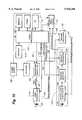
- FIG. 10is a block diagram illustrating the signal filtering technique of the present invention.
- FIG. 11is a front view of a mounting bracket for mounting the range finding apparatus shown in FIGS. 1-9 to a tripod.
- FIG. 12is a section of the mounting bracket shown in FIG. 11, taken along the line 12--12 of FIG. 11.
- FIG. 13is a front view of a clip for mounting the range finding apparatus shown in FIGS. 1-9 to an operator's belt.
- FIG. 14is a section of the clip shown in FIG. 13, taken along the line 14--14 of FIG. 13.
- FIGS. 1-9A preferred embodiment of a compact laser-based distance-based measuring apparatus 10 of the present invention is shown in FIGS. 1-9.
- the apparatus 10is referred to herein as a range finding apparatus, it should be understood that the term range finding apparatus is intended to include any device incorporating any combination of conventional surveying/measuring functions including, for example, range, azimuth, inclination, coordinate, height, and remote diameter or width determinations.
- the range finding apparatus 10includes a compact housing 12 to which is mounted a sighting device 14.
- the housing 12defines an internal chamber (not shown) in which signal emitting circuitry (not shown), a signal emitting lens 16, signal receiving circuitry (not shown) and a receiving lens 18 for receiving reflected signals, are positioned.
- the range finding apparatus 10 of the preferred embodimentis specially adapted to be held by a single hand 20 of an operator secured and steadied by the thumb 22 of the hand 20, and operatively controlled by movements of the fingers of the same hand 20.
- the housing 12 of the preferred embodimentincludes upper and lower sections 24 and 26, right and left side sections 28 and 30, and front and back panels 32 and 34.
- the upper, lower, left and right side sections 24, 26, 28, and 30are preferably portions of a one piece extruded aluminum tubular housing body.
- the front and back panels 32 and 34are conventionally fastened to the housing body to close and provide a moisture barrier for the housing 10.
- the upper section 24includes an apex portion 36 to which is mounted the sighting device 14, preferably a red dot sighting scope.
- the sighting device 14includes a viewing end 38 adjacent the back panel 34.
- Positioned on the upper section 24 adjacent the right side section 28is a right control panel 40 containing first set of control buttons 42a, 42b and 42c.
- Positioned on the upper section 24 adjacent the left side section 30is a left control panel 44 containing a second set of control buttons 46a, 46b and 46c.
- the control panels 40 and 44 and the associated control buttonsare preferably identical to each other.
- a thumb rest 48having a base portion 50, an outwardly projecting flange 51 extending from the base portion 50 and a strap retaining plate 53 fastened to the base portion 50 via fastener 54.
- the retaining plate 53has a slot 52 therethrough.
- the fastener screw 54 mounted through the retaining plate 53 and the base portion 50attaches the thumb rest 48 to the right side section 28 of the housing 12 via a threaded bore 64 (not visible in the right side section 28 as illustrated).
- the slot 52is adapted to receive one end of an elongated strap 56.
- the opposing end of the strap 56is received in a slot 58 formed in an anchor plate 60, which is mounted to the housing 12 by a fastener screw 62 in another threaded bore 64 in the right side section 28 adjacent the lower section 26, at a height which is lower than the attachment position of the thumb rest 48.
- a pair of threaded apertures 64which are spaced directly opposite to the threaded bores or apertures 64 in the right side section 28. These apertures 64 are adapted to receive a left-handed thumb rest, (a mirror image of the thumb rest 48 shown in the Figures), the strap 56 and the anchor plate 60 so that a left handed user may operate the apparatus with only one hand.
- This left handed configurationis shown in phantom dashed lines in FIG. 7 and may be simply visualized by the reader by reversing the side location of the strap 56, the anchor plate 60, and installing a left thumb rest.
- the apertures 64 on the side section 28 or 30 not used to fasten the strap 56 to the housing 12may be used to mount a tripod mounting bracket 66 (FIGS. 11 and 12), or attach a belt attachment clip 68 for mounting the range finding apparatus 10 on the belt of the operator when the apparatus is not in use.
- the front panel 32is a generally flat aluminum plate member which supports the transmitting and receiving lenses 16 and 18.
- the front panel 32is fastened to the housing 12 with four screws 71.
- the front panel 32 of the apparatus 10has a signal emitting aperture 69 which is covered by the lens 16. Also formed in the front panel 32 is a signal receiving aperture 70 which is covered by the receiving lens 18.
- An LCD display panel 72is mounted to the back panel 34. As is described in further detail below, when the apparatus 10 is actuated, the display panel 72 displays a series of menus options containing instructions and selections for the operator, as well as displaying indications of measurements and determinations made by the apparatus 10. Beneath the display panel 72 on the back panel 34 is a battery cap 74 threaded into corresponding threads in a bore (not shown) through the back panel 34 which circumscribes a cylindrical compartment (not shown) extending into the internal chamber (not shown). The cylindrical compartment holds a power supply, such as a pair of AA batteries (not shown) mounted end to end, which provides power to the apparatus 10.
- a power supplysuch as a pair of AA batteries (not shown) mounted end to end, which provides power to the apparatus 10.
- a connector 76Adjacent the battery cap 74 on the back panel 34 is a connector 76, such as preferably an RS232 serial output port, mounted through another bore through the back panel 34 through which data can be downloaded from the apparatus 10 via an appropriate cable, to a remote device such as a computer, a data-logger, or printer.
- an aperture 78which surrounds a stainless steel grill of a diaphragm speaker 80.
- the speaker 80is adapted to emit a predetermined tone from a plurality of predetermined tones, each of which corresponds to a predetermined frequency of vibration of the speaker 80.
- the speaker 80emits a predetermined audible tone in response to certain events, such as target acquisition by the receiver circuitry.
- a different audible tonemay be provided for different events so that the user can tell, without actually looking at the display panel 72, what mode of operation the apparatus 10 is in or what measuring function is anticipated as being performed, such as direct distance or horizontal distance, or inclination measurement.
- the housing 12is a one-piece aluminum housing.
- the end panels 32 and 34are gasketed to the housing 12 to make the structure water proof.
- the sides 28 and 30have a non-slip grip surface.
- the aluminum constructioncontributes to the light weight of the apparatus 10, which preferably weighs at most approximately 2.2 pounds.
- the apparatus 10is compact in size, have preferred dimensions of approximately 6 inches from front panel to back panel 34, approximately 5 inches in height from the lower section to the top of the sighting device, and approximately 2.5 inches in width measured across the front panel 32 from right side section 28 to left side section 30.
- the upper section 24 of the housing 12is divided into three straight, axially extending portions: the apex portion 36, left control panel portion 44 and right control panel portion 40. These portions are joined together to form an overall curved upper section shape which has an overall larger radius of curvature than the lower section.
- the lower section 26is rounded, with has a radius of curvature optimized to allow the lower section of the apparatus 10 to comfortably fit in the hand of the typical user.
- the upper section right and left control panels 44 and 40, the apex portion 36 of the upper section 24, and the right and left side sections 28 and 30join together forming faceted surfaces between their respective intersecting edges.
- the apparatus 10has a maximum range of at least 500 meters, a range resolution of up to 0.01 meters, and an inclination limit of plus or minus 180 degrees with an inclination accuracy of about ⁇ 0.1 degrees.
- the range finding apparatus 10 of the present inventionalso includes a user selectable electronic filter which can reject spurious reflected signals from non-target objects.
- the electronic filter of the present inventionis designed for use with high reflectivity objects, and is ideally suited for use where the user mounts a reflector on the target so that the desired reflected signal from the target is known to have a substantially higher amplitude than the spurious reflections from non-target objects.
- the user of the ranging device 10 of the present inventioncan be visually prompted using the display 72 as to enable or disable the electronic filter.
- the processorBased on the user input received through the user control of the ranging device 10, the processor enables or disables the electronic filter in the received section of the ranging device 10.
- the laser-based ranging device 10rejects spurious reflections from non-target objects through the use of either an adjustment of sensitivity or gain of the receive section of the ranging device 10, or by raising the signal threshold point to where the processor recognizes a valid reflected signal received.
- the present inventioncan utilize any of these filtering methods in any combination which is preferably determined by software.
- a reflectorcan be optionally mounted on the desired target to ensure that the reflected signal from the desired target is of sufficient power to be detected and processed by the receive section of the ranging device operating in high-reflectivity mode.
- the laser based ranging device 10 of the present inventiondisables the electronic filter mode thereby placing the ranging device in a normal mode of operation.
- the processoractivates one or more control lines from the processor to the circuits in the receive section of the ranging device. Specifically, these control lines initiate a decrease in the receive diode sensitivity by changing the diode bias voltage and/or by a decrease in gain of the receiver amplifier which decreases the sensitivity of the receive section. Additionally, the processor can increase the minimum required signal threshold level for processing any received signal pulse. In this manner, only reflected signals with sufficient magnitude will be processed, thereby increasing the likelihood that the reflected pulse used in the ranging calculation corresponds to the reflected pulse from the desired target. Further, the software can include a pre-set lookup limit to fine tune the level of acceptable reflected pulses.
- FIG. 10illustrates a block diagram of one embodiment of the apparatus 10 of the present invention.
- the laser-based range finder 10has a microprocessor 112 coupled to the display 72, the control keypads 40 and 44 for user input, a precision timing circuit 114, a laser pulse receiver 116 and a laser pulse transmitter 118.
- the microprocessor 112is also coupled to a power supply 120, a memory 122 and serial communications port connector 76.
- the laser pulse receiver 116includes a laser diode 124 connected diode operating circuit 126 which is in turn connected to a receiver amplifier 128 and then to a comparator 130.
- the comparator 130in turn provides its output to the precision timing circuit 114.
- the comparator 130receives a threshold control signal via line 132 from the microprocessor 112.
- the receiver amplifier 128receives a gain control signal also from the microprocessor 112 via line 134.
- the receiver diode operating circuit 126receives a diode bias control signal via line 137 from a receiver regulator 136 which in turn receives a control signal via line 138 from the microprocessor 112.
- the laser pulse transmitter 118includes a laser transmit diode 140 and receives a fire command via line 142 from the processor 112.
- the laser pulse transmitter 118sends a timing reference signal via line 144 to the precision timing circuit 114 and also receives a transmitter bias control signal via line 146 from a transmit regulator 148.
- the transmit regulator 148is in turn controlled by the microprocessor 112 via line 150.
- the filter function of the present inventionis introduced in the high reflectivity mode selected by the user from a visual prompt on display 72.
- the filter function in accordance with the present inventionis implemented via software and involves one or more of four elements.
- the first elementis the receiver bias control provided via line 137 to the receive diode circuit 126.
- the bias on this linemay be increased or decreased by the microprocessor to change the sensitivity of the receiver diode 124 directly. For example, when using an APD detector, its gain can be altered simply by changing the diode operating bias. However, if a pin diode is being used, another method is required as the gain is fixed.
- the second elementis the amplifier gain control signal provided on line 134 to the amplifier 128 from the microprocessor 112.
- the third elementis provided by the threshold control signal on line 132 from the microprocessor 112.
- the threshold below which amplified reflection pulse signals will be stoppedis changed by the voltage provided on line 132. Changing this threshold voltage on line 132 will change the overall sensitivity of the receiver
- the softwarehas the ability of accepting and processing only those received pulses which exceed a predetermined signal threshold magnitude.
- the high reflectivity mode of operationmay be programmed to utilize any one of these elements either alone or in any combination to provide an overall sensitivity change so as to only be responsive to high reflectivity signals. Conversely, when the user de-selects high-reflectivity mode, processor 112 disables the gain and/or threshold selection elements discussed above so that the settings of receiver 116 gains and thresholds are restored to normal.
- the calibration for the range finding device 10may be modified between the filtered and unfiltered modes. Calibration is necessary to compensate for the return signal power variations, which affect the determined distance (range) values.
- the surface of the desired targetaffects the pulse width of the return signal, which in turn, results in a timing difference at the leading edge of the pulse where the counter is initiated, which further affects the calculated flight time, and thus distance. Since the filter on mode or high reflectivity on mode adjusts some of the circuit characteristics as described above, the calibration values to apply to the filtered return signals may be different than the calibration values to be used for the filter off mode.
- the deviceis tested by targeting the signal at a prism at a fixed distance to get a wide range of return signal power variance or, the return signal power variance can be simulated with filters. This testing generates the calibration table values which are then compared to actual distance values inputted by the user.
- the keypads 44 and 40each have three buttons.
- One panelis designated via software as the primary panel.
- the otheris the secondary panel.
- the primary panelis the only panel used during measurement operations.
- the secondary panelis only used for control editing, calibration functions, and power on/off operations of the sighting device and the display.
- the button nearest the rear panel (42a, 46a)is termed the "fire" button.
- the middle button (42b, 46b)typically scrolls forward through the operating modes or options.
- the front button (42c, 46c)scrolls the operator backwards through the various available modes and/or options.
- different measurement modesmay include slope distance, height, horizontal distance, inclination, vertical distance, and multiple measurements.
- Selectable optionsmay include measurement gating, range offsets, pivot offsets, and filtering.
- the current mode or optionis indicated on the display 72 as the buttons are depressed.
- the displaypreferably indicates such conditions as battery, laser firing, and indications for which measurements the instrument is set to take, such as a base measurement when in the height measurement mode or a first measurement during tilt calibration.
- Each keypad 44 or 40may be configured as the primary keypad with the other being configured as a secondary keypad, depending on whether the user is right or left handed. This is done via software in processor 112.
- the primary keypadis configured by simply toggling one of the system software system settings via the current primary control panel Fire, Back and Forward buttons.
- buttons of the primary control panel 44 or 40 and the three buttons of the secondary control panelselect and/or scroll through options and modes, and these modes and options are visually indicated on the display 72, the user need not continually refer to an instruction manual to operate the apparatus 10. The user can simply and conveniently select which mode and option to utilize, take the indicated measurements with one hand, and record or download the measured data.
- the present inventionmay be practiced otherwise than as specifically described above. Many changes, alternatives, variations, and equivalents to the various structures shown and described will be apparent to one skilled in the art.
- the two apertures 16 and 18 in the front panelmay be combined in a single aperture with the transmitted and reflected signals traveling the same path.
- the control panels or keypads 40 and 44may be arranged with four buttons rather than three as shown in the figures.
- the buttonsmay also be arranged other than in a straight line as shown. For example, they may be arranged along a curve approximating a normal reach of each of three or the four fingers on one's hand.
Landscapes
- Physics & Mathematics (AREA)
- General Physics & Mathematics (AREA)
- Engineering & Computer Science (AREA)
- Electromagnetism (AREA)
- Radar, Positioning & Navigation (AREA)
- Remote Sensing (AREA)
- Computer Networks & Wireless Communication (AREA)
- Optical Radar Systems And Details Thereof (AREA)
- Measurement Of Optical Distance (AREA)
Abstract
Description
Claims (12)
Priority Applications (5)
| Application Number | Priority Date | Filing Date | Title |
|---|---|---|---|
| US08/926,598US5926260A (en) | 1995-01-19 | 1997-08-21 | Compact laser-based distance measuring apparatus |
| CA002263853ACA2263853C (en) | 1996-08-22 | 1997-08-22 | Compact laser-based distance measuring apparatus |
| PCT/US1997/014899WO1998008052A1 (en) | 1996-08-22 | 1997-08-22 | Compact laser-based distance measuring apparatus |
| EP97939537AEP1015847A4 (en) | 1996-08-22 | 1997-08-22 | Compact laser-based distance measuring apparatus |
| AU41606/97AAU729740B2 (en) | 1996-08-22 | 1997-08-22 | Compact laser-based distance measuring apparatus |
Applications Claiming Priority (4)
| Application Number | Priority Date | Filing Date | Title |
|---|---|---|---|
| US08/375,941US5574552A (en) | 1995-01-19 | 1995-01-19 | Self-calibrating precision timing circuit and method for a laser range finder |
| US2453996P | 1996-08-22 | 1996-08-22 | |
| US08/717,635US5703678A (en) | 1995-01-19 | 1996-09-23 | Self-calibrating precision timing circuit and method for a laser range finder |
| US08/926,598US5926260A (en) | 1995-01-19 | 1997-08-21 | Compact laser-based distance measuring apparatus |
Related Parent Applications (1)
| Application Number | Title | Priority Date | Filing Date |
|---|---|---|---|
| US08/717,635Continuation-In-PartUS5703678A (en) | 1995-01-19 | 1996-09-23 | Self-calibrating precision timing circuit and method for a laser range finder |
Publications (1)
| Publication Number | Publication Date |
|---|---|
| US5926260Atrue US5926260A (en) | 1999-07-20 |
Family
ID=26698570
Family Applications (1)
| Application Number | Title | Priority Date | Filing Date |
|---|---|---|---|
| US08/926,598Expired - LifetimeUS5926260A (en) | 1995-01-19 | 1997-08-21 | Compact laser-based distance measuring apparatus |
Country Status (5)
| Country | Link |
|---|---|
| US (1) | US5926260A (en) |
| EP (1) | EP1015847A4 (en) |
| AU (1) | AU729740B2 (en) |
| CA (1) | CA2263853C (en) |
| WO (1) | WO1998008052A1 (en) |
Cited By (61)
| Publication number | Priority date | Publication date | Assignee | Title |
|---|---|---|---|---|
| WO2001090691A1 (en)* | 2000-04-14 | 2001-11-29 | Optical Air Data Systems, Lp | Multi-function optical system and assembly |
| EP1420268A1 (en)* | 2002-11-13 | 2004-05-19 | HILTI Aktiengesellschaft | Hand-held laser distance measuring device |
| US20040239914A1 (en)* | 2002-03-26 | 2004-12-02 | Joerg Stierle | Device and accessory |
| US20050002015A1 (en)* | 2003-07-01 | 2005-01-06 | Ing-Song Lin | Method and device for light signal reception |
| US20050110976A1 (en)* | 2003-11-26 | 2005-05-26 | Labelle John | Rangefinder with reduced noise receiver |
| US20050110977A1 (en)* | 2003-11-26 | 2005-05-26 | Labelle John | Rangefinder and method for collecting calibration data |
| US20050115141A1 (en)* | 2002-03-04 | 2005-06-02 | Larry Holmberg | Range finder |
| US20050171712A1 (en)* | 2004-01-29 | 2005-08-04 | Kabushiki Kaisha Topcon | Processing apparatus for pulsed signal and processing method for pulsed signal and program therefor |
| US20050195385A1 (en)* | 2002-03-04 | 2005-09-08 | Larry Holmberg | Range finder |
| US20060100816A1 (en)* | 2002-08-09 | 2006-05-11 | Surveylab Group Limited | Mobile instrument, viewing device, and methods of processing and storing information |
| US20070157502A1 (en)* | 2006-01-06 | 2007-07-12 | Larry Holmberg | Device mount for a firearm |
| US20080000465A1 (en)* | 2006-06-30 | 2008-01-03 | Larry Holmberg | Adaptor for device mount |
| US20080000463A1 (en)* | 2006-06-30 | 2008-01-03 | Larry Holmberg | Crossbow device mount |
| US20080001057A1 (en)* | 2006-06-30 | 2008-01-03 | Larry Holmberg | Device mount |
| US20080087784A1 (en)* | 2006-10-17 | 2008-04-17 | Larry Holmberg | Device mount with stabilizing function |
| EP1913802A2 (en)* | 2005-08-01 | 2008-04-23 | Robert Bosch Gmbh | Measuring device |
| US20080164392A1 (en)* | 2007-01-05 | 2008-07-10 | Larry Holmberg | Device mount system for a weapon |
| US7505119B2 (en) | 2001-04-13 | 2009-03-17 | Optical Air Data Systems, Llc | Multi-function optical system and assembly |
| RU2362120C1 (en)* | 2007-12-12 | 2009-07-20 | Закрытое акционерное общество "Скат-Р" | Laser range finder |
| US20090213358A1 (en)* | 2004-10-13 | 2009-08-27 | Bushnell Inc. | Method, device, and computer program for determining a range to a target |
| DE202008005314U1 (en)* | 2008-04-17 | 2009-09-03 | Sick Ag | Distance sensor |
| US20090255163A1 (en)* | 2002-03-04 | 2009-10-15 | Larry Holmberg | Device mounting system for a weapon |
| WO2009133414A1 (en) | 2008-05-02 | 2009-11-05 | Marko Borosak | Pulsed-laser beam detector with improved sun and temperature compensation |
| US20100066899A1 (en)* | 1999-03-08 | 2010-03-18 | Larry Holmberg | Video camera with mount |
| US20100115778A1 (en)* | 2008-11-10 | 2010-05-13 | Gorsuch Timothy M | Auto-correcting bow sight |
| US7739822B1 (en) | 2007-01-09 | 2010-06-22 | Larry Holmberg | Method and device for mounting an accessory to a firearm |
| US7780363B1 (en) | 2008-01-17 | 2010-08-24 | Larry Holmberg | Device for mounting imaging equipment to a bow and method of recording a hunt |
| US20100313461A1 (en)* | 2009-06-16 | 2010-12-16 | Larry Holmberg | Electronic device mount system with strap |
| US20110037968A1 (en)* | 2009-08-13 | 2011-02-17 | Nen-Tsua Li | Laser rangefinder with a voice control function |
| DE202008018045U1 (en) | 2008-05-02 | 2011-05-19 | Borosak, Marko | Pulsed laser beam detector with improved solar and temperature compensation |
| US20110121159A1 (en)* | 2009-11-23 | 2011-05-26 | Fraser-Volpe, Llc | Portable integrated laser optical target tracker |
| US8024884B2 (en) | 2009-06-16 | 2011-09-27 | Larry Holmberg | Electronic device mount system for weapons |
| US20110308130A1 (en)* | 1999-03-08 | 2011-12-22 | Larry Holmberg | Range finder |
| US8240077B2 (en) | 2002-03-04 | 2012-08-14 | Larry Holmberg | Range finder for weapons |
| US8411257B2 (en) | 2010-05-11 | 2013-04-02 | Laser Technology, Inc. | Folded path laser rangefinder architecture and technique incorporating a single circuit board for mounting of both laser emitting and detecting elements |
| US8656625B2 (en) | 2010-12-29 | 2014-02-25 | Larry Holmberg | Accessory mount |
| US8656624B2 (en) | 2010-12-29 | 2014-02-25 | Larry Holmberg | Universal device mount |
| CN104133220A (en)* | 2013-05-03 | 2014-11-05 | 罗伯特·博世有限公司 | Rangefinder |
| USD729863S1 (en) | 2014-01-30 | 2015-05-19 | Wisconsin Archery Products Llc | Camera mount |
| USD753210S1 (en) | 2014-01-30 | 2016-04-05 | Wisconsin Archery Products Llc | Camera mount |
| USD757843S1 (en) | 2014-01-30 | 2016-05-31 | Wisconsin Archery Products Llc | Camera mount |
| US9784824B2 (en) | 2014-10-27 | 2017-10-10 | Laser Technology, Inc. | Pseudo-stabilization technique for laser-based speed and rangefinding instruments utilizing a rate gyroscope to track pitch and yaw deviations from the aiming point |
| US9874441B1 (en)* | 2013-01-16 | 2018-01-23 | Opti-Logic Corporation | Circuitry and method for reducing echo walk error in a time-of-flight laser distance device |
| US10094662B1 (en) | 2017-03-28 | 2018-10-09 | Trimble Inc. | Three-dimension position and heading solution |
| USD842723S1 (en) | 2017-09-27 | 2019-03-12 | Bushnell Inc. | Rangefinder |
| US10300573B2 (en) | 2017-05-24 | 2019-05-28 | Trimble Inc. | Measurement, layout, marking, firestop stick |
| US10339670B2 (en) | 2017-08-29 | 2019-07-02 | Trimble Inc. | 3D tool tracking and positioning using cameras |
| US10341618B2 (en) | 2017-05-24 | 2019-07-02 | Trimble Inc. | Infrastructure positioning camera system |
| US10347008B2 (en) | 2017-08-14 | 2019-07-09 | Trimble Inc. | Self positioning camera system to 3D CAD/BIM model |
| US10393517B2 (en) | 2014-10-27 | 2019-08-27 | Laser Technology, Inc. | Laser source modification techniques for a laser-based rangefinding or speed measurement instrument enabling increased range with improved accuracy |
| US10406645B2 (en) | 2017-05-24 | 2019-09-10 | Trimble Inc. | Calibration approach for camera placement |
| USD875200S1 (en) | 2018-01-03 | 2020-02-11 | Bushnell Inc. | Rangefinder display device |
| USD880568S1 (en) | 2016-11-22 | 2020-04-07 | Wisconsin Archery Products Llc | Camera mount |
| US10997747B2 (en) | 2019-05-09 | 2021-05-04 | Trimble Inc. | Target positioning with bundle adjustment |
| US11002541B2 (en) | 2019-07-23 | 2021-05-11 | Trimble Inc. | Target positioning with electronic distance measuring and bundle adjustment |
| USD926606S1 (en) | 2017-11-01 | 2021-08-03 | Bushnell Inc. | Rangefinder |
| US11168982B2 (en) | 2017-02-14 | 2021-11-09 | Laser Technology, Inc. | Laser-based rangefinding instrument |
| US20220111282A1 (en)* | 2020-10-08 | 2022-04-14 | Precision Pro Sports, Llc | Personalized adjusted yardage recommendation systems |
| US12007477B2 (en) | 2019-01-07 | 2024-06-11 | Bushnell Inc. | Golf rangefinder device with integral magnet mount |
| USD1084206S1 (en) | 2018-01-03 | 2025-07-15 | Bushnell Inc. | Rangefinder display screen |
| EP4610664A2 (en) | 2017-09-27 | 2025-09-03 | Bushnell Inc. | Golf laser rangefinders |
Families Citing this family (3)
| Publication number | Priority date | Publication date | Assignee | Title |
|---|---|---|---|---|
| DE19804050B4 (en)* | 1998-02-03 | 2006-02-16 | Robert Bosch Gmbh | Device for optical distance measurement |
| RU2164005C2 (en)* | 1998-05-13 | 2001-03-10 | ИЧП "Будыльникова БАС" | Light range finder |
| FR2875711A1 (en)* | 2004-09-30 | 2006-03-31 | Materne Warter | Regulation distance measuring device for e.g. football match, has alert unit to indicate that distance measured by distance meter is situated in distance range including distance, or lesser or greater than range |
Citations (17)
| Publication number | Priority date | Publication date | Assignee | Title |
|---|---|---|---|---|
| US3464770A (en)* | 1964-11-07 | 1969-09-02 | Leitz Ernst Gmbh | Combined sighting mechanism and laser range finder |
| US3654477A (en)* | 1970-06-02 | 1972-04-04 | Bionic Instr Inc | Obstacle detection system for use by blind comprising plural ranging channels mounted on spectacle frames |
| US3832056A (en)* | 1972-03-13 | 1974-08-27 | Aga Corp | Distance measuring device using electro-optical techniques |
| US4214242A (en)* | 1977-12-08 | 1980-07-22 | International Standard Electric Corporation | Method and apparatus for eliminating multiple-time echoes in pulse Doppler radars |
| US4346989A (en)* | 1976-11-18 | 1982-08-31 | Hewlett-Packard Company | Surveying instrument |
| US4453825A (en)* | 1979-12-07 | 1984-06-12 | Hewlett-Packard Company | Distance transducer |
| US5046839A (en)* | 1990-07-30 | 1991-09-10 | Locker Enterprises, Inc. | Golf course range finder system |
| US5221956A (en)* | 1991-08-14 | 1993-06-22 | Kustom Signals, Inc. | Lidar device with combined optical sight |
| US5311271A (en)* | 1992-01-21 | 1994-05-10 | Dme/Golf, Inc. | Golf course range finder |
| US5359404A (en)* | 1989-03-27 | 1994-10-25 | Laser Technology, Inc. | Laser-based speed measuring device |
| US5418609A (en)* | 1993-09-14 | 1995-05-23 | Laser Technology, Inc. | Apparatus and method for mounting a range finding instrument to a theodolite telescope |
| US5574552A (en)* | 1995-01-19 | 1996-11-12 | Laser Technology, Inc. | Self-calibrating precision timing circuit and method for a laser range finder |
| US5612779A (en)* | 1995-01-19 | 1997-03-18 | Laser Technology, Inc. | Automatic noise threshold determining circuit and method for a laser range finder |
| US5623335A (en)* | 1995-05-04 | 1997-04-22 | Bushnell Corporation | Laser range finder with target quality display |
| US5652651A (en)* | 1995-01-19 | 1997-07-29 | Laser Technology, Inc. | Laser range finder having selectable target acquisition characteristics and range measuring precision |
| US5669174A (en)* | 1993-06-08 | 1997-09-23 | Teetzel; James W. | Laser range finding apparatus |
| US5760887A (en)* | 1996-04-30 | 1998-06-02 | Hughes Electronics | Multi-pulse, multi-return, modal range processing for clutter rejection |
Family Cites Families (4)
| Publication number | Priority date | Publication date | Assignee | Title |
|---|---|---|---|---|
| US4730190A (en)* | 1986-10-29 | 1988-03-08 | Winlam Company | Hand-held measuring device |
| GB8908375D0 (en)* | 1989-04-13 | 1989-06-01 | Measurement Devices Ltd | Hand-held laser rangefinder |
| JP3151066B2 (en)* | 1992-09-24 | 2001-04-03 | マツダ株式会社 | Distance detection device |
| CA2187909A1 (en)* | 1994-05-09 | 1995-11-16 | Patrick J. Murphy | Hand-held distance-measurement apparatus and system |
- 1997
- 1997-08-21USUS08/926,598patent/US5926260A/ennot_activeExpired - Lifetime
- 1997-08-22EPEP97939537Apatent/EP1015847A4/ennot_activeWithdrawn
- 1997-08-22CACA002263853Apatent/CA2263853C/ennot_activeExpired - Lifetime
- 1997-08-22AUAU41606/97Apatent/AU729740B2/ennot_activeExpired
- 1997-08-22WOPCT/US1997/014899patent/WO1998008052A1/ennot_activeApplication Discontinuation
Patent Citations (17)
| Publication number | Priority date | Publication date | Assignee | Title |
|---|---|---|---|---|
| US3464770A (en)* | 1964-11-07 | 1969-09-02 | Leitz Ernst Gmbh | Combined sighting mechanism and laser range finder |
| US3654477A (en)* | 1970-06-02 | 1972-04-04 | Bionic Instr Inc | Obstacle detection system for use by blind comprising plural ranging channels mounted on spectacle frames |
| US3832056A (en)* | 1972-03-13 | 1974-08-27 | Aga Corp | Distance measuring device using electro-optical techniques |
| US4346989A (en)* | 1976-11-18 | 1982-08-31 | Hewlett-Packard Company | Surveying instrument |
| US4214242A (en)* | 1977-12-08 | 1980-07-22 | International Standard Electric Corporation | Method and apparatus for eliminating multiple-time echoes in pulse Doppler radars |
| US4453825A (en)* | 1979-12-07 | 1984-06-12 | Hewlett-Packard Company | Distance transducer |
| US5359404A (en)* | 1989-03-27 | 1994-10-25 | Laser Technology, Inc. | Laser-based speed measuring device |
| US5046839A (en)* | 1990-07-30 | 1991-09-10 | Locker Enterprises, Inc. | Golf course range finder system |
| US5221956A (en)* | 1991-08-14 | 1993-06-22 | Kustom Signals, Inc. | Lidar device with combined optical sight |
| US5311271A (en)* | 1992-01-21 | 1994-05-10 | Dme/Golf, Inc. | Golf course range finder |
| US5669174A (en)* | 1993-06-08 | 1997-09-23 | Teetzel; James W. | Laser range finding apparatus |
| US5418609A (en)* | 1993-09-14 | 1995-05-23 | Laser Technology, Inc. | Apparatus and method for mounting a range finding instrument to a theodolite telescope |
| US5574552A (en)* | 1995-01-19 | 1996-11-12 | Laser Technology, Inc. | Self-calibrating precision timing circuit and method for a laser range finder |
| US5612779A (en)* | 1995-01-19 | 1997-03-18 | Laser Technology, Inc. | Automatic noise threshold determining circuit and method for a laser range finder |
| US5652651A (en)* | 1995-01-19 | 1997-07-29 | Laser Technology, Inc. | Laser range finder having selectable target acquisition characteristics and range measuring precision |
| US5623335A (en)* | 1995-05-04 | 1997-04-22 | Bushnell Corporation | Laser range finder with target quality display |
| US5760887A (en)* | 1996-04-30 | 1998-06-02 | Hughes Electronics | Multi-pulse, multi-return, modal range processing for clutter rejection |
Non-Patent Citations (2)
| Title |
|---|
| RCA AN/GUS 5; Burlington, MA 01803; Aug. 30, 1976.* |
| RCA AN/GUS-5; Burlington, MA 01803; Aug. 30, 1976. |
Cited By (117)
| Publication number | Priority date | Publication date | Assignee | Title |
|---|---|---|---|---|
| US7965337B2 (en) | 1999-03-08 | 2011-06-21 | Larry Holmberg | System for mounting camera on bow |
| US20100066899A1 (en)* | 1999-03-08 | 2010-03-18 | Larry Holmberg | Video camera with mount |
| US9521300B2 (en) | 1999-03-08 | 2016-12-13 | Larry Holmberg | Camera for mounting |
| US9143663B2 (en) | 1999-03-08 | 2015-09-22 | Larry Holmberg | Camera for mounting |
| US8717497B2 (en) | 1999-03-08 | 2014-05-06 | Larry Holmberg | Camera for mounting |
| US20100128166A1 (en)* | 1999-03-08 | 2010-05-27 | Larry Holmberg | Camera for mounting |
| US8717496B2 (en) | 1999-03-08 | 2014-05-06 | Larry Holmberg | Rail mount |
| US8059196B2 (en) | 1999-03-08 | 2011-11-15 | Larry Holmberg | Camera for mounting |
| US7880793B2 (en) | 1999-03-08 | 2011-02-01 | Larry Holmberg | Camera with mounting rail |
| US8045038B2 (en) | 1999-03-08 | 2011-10-25 | Larry Holmberg | Video camera with mount |
| US8035735B2 (en) | 1999-03-08 | 2011-10-11 | Larry Holmberg | Camera with weather cover |
| US20110308130A1 (en)* | 1999-03-08 | 2011-12-22 | Larry Holmberg | Range finder |
| WO2001090691A1 (en)* | 2000-04-14 | 2001-11-29 | Optical Air Data Systems, Lp | Multi-function optical system and assembly |
| EP1281042A4 (en)* | 2000-04-14 | 2010-08-11 | Optical Air Data Systems Lp | Multi-function optical system and assembly |
| US7505119B2 (en) | 2001-04-13 | 2009-03-17 | Optical Air Data Systems, Llc | Multi-function optical system and assembly |
| US20060254116A1 (en)* | 2002-03-04 | 2006-11-16 | Holmberg Larry A | Range finder |
| US20100071247A1 (en)* | 2002-03-04 | 2010-03-25 | Larry Holmberg | Range finder |
| US20050115141A1 (en)* | 2002-03-04 | 2005-06-02 | Larry Holmberg | Range finder |
| US7982858B2 (en) | 2002-03-04 | 2011-07-19 | Larry Holmberg | Range finder |
| US7643132B2 (en) | 2002-03-04 | 2010-01-05 | Larry Holmberg | Range finder |
| US8656629B2 (en) | 2002-03-04 | 2014-02-25 | Larry Holmberg | Range finder for weapons |
| US20090255163A1 (en)* | 2002-03-04 | 2009-10-15 | Larry Holmberg | Device mounting system for a weapon |
| US7100321B2 (en) | 2002-03-04 | 2006-09-05 | Larry Holmberg | Range finder |
| US8240077B2 (en) | 2002-03-04 | 2012-08-14 | Larry Holmberg | Range finder for weapons |
| US20050195385A1 (en)* | 2002-03-04 | 2005-09-08 | Larry Holmberg | Range finder |
| US6988331B2 (en) | 2002-03-04 | 2006-01-24 | Larry Holmberg | Range finder |
| US8156680B2 (en) | 2002-03-04 | 2012-04-17 | Larry Holmberg | Device mounting system for a weapon |
| US7259837B2 (en)* | 2002-03-26 | 2007-08-21 | Robert Bosch Gmbh | Device for releasable fastening of an accessory and accessory for such a device |
| US20040239914A1 (en)* | 2002-03-26 | 2004-12-02 | Joerg Stierle | Device and accessory |
| US20060100816A1 (en)* | 2002-08-09 | 2006-05-11 | Surveylab Group Limited | Mobile instrument, viewing device, and methods of processing and storing information |
| US20090082991A1 (en)* | 2002-08-09 | 2009-03-26 | Surveylab Group Limited | Mobile Instrument, Viewing Device, and Methods of Processing and Storing Information |
| US8024151B2 (en) | 2002-08-09 | 2011-09-20 | Surveylab Group Ltd. | Mobile instrument, viewing device, and methods of processing and storing information |
| US7647197B2 (en) | 2002-08-09 | 2010-01-12 | Surveylab Group Limited | Mobile instrument, viewing device, and methods of processing and storing information |
| EP1420268A1 (en)* | 2002-11-13 | 2004-05-19 | HILTI Aktiengesellschaft | Hand-held laser distance measuring device |
| US20040135991A1 (en)* | 2002-11-13 | 2004-07-15 | Torsten Gogolla | Portable laser distance measuring device |
| US20050002015A1 (en)* | 2003-07-01 | 2005-01-06 | Ing-Song Lin | Method and device for light signal reception |
| US7193689B2 (en)* | 2003-07-01 | 2007-03-20 | Asia Optical Co., Inc. | Method and device for light signal reception |
| US20050110976A1 (en)* | 2003-11-26 | 2005-05-26 | Labelle John | Rangefinder with reduced noise receiver |
| US20050110977A1 (en)* | 2003-11-26 | 2005-05-26 | Labelle John | Rangefinder and method for collecting calibration data |
| US7053992B2 (en) | 2003-11-26 | 2006-05-30 | Meade Instruments Corporation | Rangefinder and method for collecting calibration data |
| US7508497B2 (en) | 2003-11-26 | 2009-03-24 | Meade Instruments Corporation | Rangefinder with reduced noise receiver |
| US20060215149A1 (en)* | 2003-11-26 | 2006-09-28 | Labelle John | Rangefinder and method for collecting calibration data |
| US7414707B2 (en) | 2003-11-26 | 2008-08-19 | Meade Instruments Corporation | Rangefinder and method for collecting calibration data |
| US20050171712A1 (en)* | 2004-01-29 | 2005-08-04 | Kabushiki Kaisha Topcon | Processing apparatus for pulsed signal and processing method for pulsed signal and program therefor |
| US7518709B2 (en)* | 2004-01-29 | 2009-04-14 | Kabushiki Kaisha Topcon | Processing apparatus for pulsed signal and processing method for pulsed signal and program therefor |
| US7859650B2 (en)* | 2004-10-13 | 2010-12-28 | Bushnell Inc. | Method, device, and computer program for determining a range to a target |
| US20090213358A1 (en)* | 2004-10-13 | 2009-08-27 | Bushnell Inc. | Method, device, and computer program for determining a range to a target |
| US20080151217A1 (en)* | 2005-08-01 | 2008-06-26 | Uwe Skultety-Betz | Measuring Device |
| US7952687B2 (en)* | 2005-08-01 | 2011-05-31 | Robert Bosch Gmbh | Measuring device |
| EP1913802A2 (en)* | 2005-08-01 | 2008-04-23 | Robert Bosch Gmbh | Measuring device |
| CN101233797B (en)* | 2005-08-01 | 2011-01-19 | 罗伯特·博世有限公司 | Measuring instrument and method for manufacturing such measuring instrument |
| US7574824B2 (en) | 2006-01-06 | 2009-08-18 | Larry Holmberg | Device mount for a firearm |
| US20070157502A1 (en)* | 2006-01-06 | 2007-07-12 | Larry Holmberg | Device mount for a firearm |
| US7661221B2 (en) | 2006-01-06 | 2010-02-16 | Larry Holmberg | Device mount |
| US20070157503A1 (en)* | 2006-01-06 | 2007-07-12 | Larry Holmberg | Device mount |
| US8046950B2 (en) | 2006-01-06 | 2011-11-01 | Larry Holmberg | Method of attaching device to weapon |
| US20080000465A1 (en)* | 2006-06-30 | 2008-01-03 | Larry Holmberg | Adaptor for device mount |
| US20080000463A1 (en)* | 2006-06-30 | 2008-01-03 | Larry Holmberg | Crossbow device mount |
| US20080001057A1 (en)* | 2006-06-30 | 2008-01-03 | Larry Holmberg | Device mount |
| US7647922B2 (en) | 2006-06-30 | 2010-01-19 | Larry Holmberg | Adaptor for device mount |
| US7506643B2 (en) | 2006-06-30 | 2009-03-24 | Larry Holmberg | Crossbow device mount |
| US7594352B2 (en) | 2006-10-17 | 2009-09-29 | Larry Holmberg | Device mount with stabilizing function |
| US7926220B2 (en)* | 2006-10-17 | 2011-04-19 | Larry Holmberg | Stabilizing device mount and method |
| US20080087784A1 (en)* | 2006-10-17 | 2008-04-17 | Larry Holmberg | Device mount with stabilizing function |
| US20100011649A1 (en)* | 2006-10-17 | 2010-01-21 | Larry Holmberg | Stabilizing device mount and method |
| US7891131B2 (en) | 2007-01-05 | 2011-02-22 | Larry Holmberg | Device mount system for a weapon |
| US20080164392A1 (en)* | 2007-01-05 | 2008-07-10 | Larry Holmberg | Device mount system for a weapon |
| US7739822B1 (en) | 2007-01-09 | 2010-06-22 | Larry Holmberg | Method and device for mounting an accessory to a firearm |
| RU2362120C1 (en)* | 2007-12-12 | 2009-07-20 | Закрытое акционерное общество "Скат-Р" | Laser range finder |
| US7780363B1 (en) | 2008-01-17 | 2010-08-24 | Larry Holmberg | Device for mounting imaging equipment to a bow and method of recording a hunt |
| DE202008005314U1 (en)* | 2008-04-17 | 2009-09-03 | Sick Ag | Distance sensor |
| WO2009133414A1 (en) | 2008-05-02 | 2009-11-05 | Marko Borosak | Pulsed-laser beam detector with improved sun and temperature compensation |
| US8309926B2 (en) | 2008-05-02 | 2012-11-13 | Marko Borosak | Pulsed-laser beam detector with improved sun and temperature compensation |
| DE202008018045U1 (en) | 2008-05-02 | 2011-05-19 | Borosak, Marko | Pulsed laser beam detector with improved solar and temperature compensation |
| US20100264301A1 (en)* | 2008-05-02 | 2010-10-21 | Marko Borosak | Pulsed-laser beam detector with improved sun and temperature compensation |
| US20100115778A1 (en)* | 2008-11-10 | 2010-05-13 | Gorsuch Timothy M | Auto-correcting bow sight |
| US8316551B2 (en) | 2008-11-10 | 2012-11-27 | Gorsuch Timothy M | Auto-correcting bow sight |
| US8024884B2 (en) | 2009-06-16 | 2011-09-27 | Larry Holmberg | Electronic device mount system for weapons |
| US8161674B2 (en) | 2009-06-16 | 2012-04-24 | Larry Holmberg | Electronic device mount system with strap |
| US20100313461A1 (en)* | 2009-06-16 | 2010-12-16 | Larry Holmberg | Electronic device mount system with strap |
| US20110037968A1 (en)* | 2009-08-13 | 2011-02-17 | Nen-Tsua Li | Laser rangefinder with a voice control function |
| US7903237B1 (en)* | 2009-08-13 | 2011-03-08 | Nen-Tsua Li | Laser rangefinder with a voice control function |
| US20110121159A1 (en)* | 2009-11-23 | 2011-05-26 | Fraser-Volpe, Llc | Portable integrated laser optical target tracker |
| US8378279B2 (en) | 2009-11-23 | 2013-02-19 | Fraser-Volpe, Llc | Portable integrated laser optical target tracker |
| US8411257B2 (en) | 2010-05-11 | 2013-04-02 | Laser Technology, Inc. | Folded path laser rangefinder architecture and technique incorporating a single circuit board for mounting of both laser emitting and detecting elements |
| US8656624B2 (en) | 2010-12-29 | 2014-02-25 | Larry Holmberg | Universal device mount |
| US8656625B2 (en) | 2010-12-29 | 2014-02-25 | Larry Holmberg | Accessory mount |
| US9874441B1 (en)* | 2013-01-16 | 2018-01-23 | Opti-Logic Corporation | Circuitry and method for reducing echo walk error in a time-of-flight laser distance device |
| CN104133220A (en)* | 2013-05-03 | 2014-11-05 | 罗伯特·博世有限公司 | Rangefinder |
| US20140327901A1 (en)* | 2013-05-03 | 2014-11-06 | Robert Bosch Gmbh | Rangefinder |
| US9971034B2 (en)* | 2013-05-03 | 2018-05-15 | Robert Bosch Gmbh | Rangefinder |
| CN104133220B (en)* | 2013-05-03 | 2019-08-20 | 罗伯特·博世有限公司 | Distance measuring equipment |
| USD753210S1 (en) | 2014-01-30 | 2016-04-05 | Wisconsin Archery Products Llc | Camera mount |
| USD757843S1 (en) | 2014-01-30 | 2016-05-31 | Wisconsin Archery Products Llc | Camera mount |
| USD729863S1 (en) | 2014-01-30 | 2015-05-19 | Wisconsin Archery Products Llc | Camera mount |
| US9784824B2 (en) | 2014-10-27 | 2017-10-10 | Laser Technology, Inc. | Pseudo-stabilization technique for laser-based speed and rangefinding instruments utilizing a rate gyroscope to track pitch and yaw deviations from the aiming point |
| US10393517B2 (en) | 2014-10-27 | 2019-08-27 | Laser Technology, Inc. | Laser source modification techniques for a laser-based rangefinding or speed measurement instrument enabling increased range with improved accuracy |
| USD880568S1 (en) | 2016-11-22 | 2020-04-07 | Wisconsin Archery Products Llc | Camera mount |
| US11168982B2 (en) | 2017-02-14 | 2021-11-09 | Laser Technology, Inc. | Laser-based rangefinding instrument |
| US10094662B1 (en) | 2017-03-28 | 2018-10-09 | Trimble Inc. | Three-dimension position and heading solution |
| US10341618B2 (en) | 2017-05-24 | 2019-07-02 | Trimble Inc. | Infrastructure positioning camera system |
| US10406645B2 (en) | 2017-05-24 | 2019-09-10 | Trimble Inc. | Calibration approach for camera placement |
| US10300573B2 (en) | 2017-05-24 | 2019-05-28 | Trimble Inc. | Measurement, layout, marking, firestop stick |
| US10646975B2 (en) | 2017-05-24 | 2020-05-12 | Trimble Inc. | Measurement, layout, marking, firestop stick |
| US10347008B2 (en) | 2017-08-14 | 2019-07-09 | Trimble Inc. | Self positioning camera system to 3D CAD/BIM model |
| US10339670B2 (en) | 2017-08-29 | 2019-07-02 | Trimble Inc. | 3D tool tracking and positioning using cameras |
| EP4610664A2 (en) | 2017-09-27 | 2025-09-03 | Bushnell Inc. | Golf laser rangefinders |
| USD842723S1 (en) | 2017-09-27 | 2019-03-12 | Bushnell Inc. | Rangefinder |
| USD926606S1 (en) | 2017-11-01 | 2021-08-03 | Bushnell Inc. | Rangefinder |
| USD954171S1 (en) | 2018-01-03 | 2022-06-07 | Bushnell Inc. | Rangefinder display device |
| USD1084206S1 (en) | 2018-01-03 | 2025-07-15 | Bushnell Inc. | Rangefinder display screen |
| USD875200S1 (en) | 2018-01-03 | 2020-02-11 | Bushnell Inc. | Rangefinder display device |
| US12007477B2 (en) | 2019-01-07 | 2024-06-11 | Bushnell Inc. | Golf rangefinder device with integral magnet mount |
| US10997747B2 (en) | 2019-05-09 | 2021-05-04 | Trimble Inc. | Target positioning with bundle adjustment |
| US11002541B2 (en) | 2019-07-23 | 2021-05-11 | Trimble Inc. | Target positioning with electronic distance measuring and bundle adjustment |
| US20220111282A1 (en)* | 2020-10-08 | 2022-04-14 | Precision Pro Sports, Llc | Personalized adjusted yardage recommendation systems |
| US11833404B2 (en)* | 2020-10-08 | 2023-12-05 | Precision Pro Sports, Llc | Personalized adjusted yardage recommendation systems |
Also Published As
| Publication number | Publication date |
|---|---|
| EP1015847A1 (en) | 2000-07-05 |
| CA2263853A1 (en) | 1998-02-26 |
| AU4160697A (en) | 1998-03-06 |
| WO1998008052A1 (en) | 1998-02-26 |
| AU729740B2 (en) | 2001-02-08 |
| EP1015847A4 (en) | 2001-01-24 |
| CA2263853C (en) | 2006-10-10 |
Similar Documents
| Publication | Publication Date | Title |
|---|---|---|
| US5926260A (en) | Compact laser-based distance measuring apparatus | |
| US6108071A (en) | Speed and position measurement system | |
| AU735001B2 (en) | Modularized laser-based survey system | |
| US5291262A (en) | Laser surveying instrument | |
| US4576481A (en) | Passive optical position measurement system | |
| US6873406B1 (en) | Tilt-compensated laser rangefinder | |
| RU2602992C2 (en) | Manual laser rangefinder | |
| US7409312B2 (en) | Handheld laser light detector with height correction, using a GPS receiver to provide two-dimensional position data | |
| EP3306343B1 (en) | Through-the-lens, co-aligned optical aiming system for a phase-type, laser-based distance measuring device | |
| JPH04504755A (en) | handheld laser rangefinder | |
| JP4709546B2 (en) | Distance measuring device and distance measuring method | |
| US20070175081A1 (en) | Gun sight with continuously measuring rangefinder | |
| US7327441B2 (en) | Distance measuring system | |
| US20100228517A1 (en) | Lidar devices with reflective optics | |
| US6584860B1 (en) | Flow probe insertion gauge | |
| JP2005522684A (en) | Distance measuring device | |
| US6803593B2 (en) | Distance measuring system | |
| US5212533A (en) | Light wave distance meter | |
| CN115183629B (en) | Ranging and ballistic display sighting telescope | |
| US4988193A (en) | Method and apparatus for measuring incident light angle relative to level | |
| KR100631302B1 (en) | Portable measuring instrument | |
| KR20080026863A (en) | Navigation device with split screen layout function and split screen layout method | |
| US20070101593A1 (en) | Ultrasonic distance measuring apparatus with a laser-aiming level system | |
| WO2019199735A1 (en) | Long-range laser rangefinder | |
| KR100464278B1 (en) | Device for level measurement of liquid using ultrasonic sensor and method thereof |
Legal Events
| Date | Code | Title | Description |
|---|---|---|---|
| AS | Assignment | Owner name:LASER TECHNOLOGY, INC., COLORADO Free format text:ASSIGNMENT OF ASSIGNORS INTEREST;ASSIGNORS:ZYKAN, BLAIR J.;MILLER, ERIC A.;DUNNE, JEREMY G.;REEL/FRAME:008947/0630 Effective date:19970821 | |
| STCF | Information on status: patent grant | Free format text:PATENTED CASE | |
| FEPP | Fee payment procedure | Free format text:PAYOR NUMBER ASSIGNED (ORIGINAL EVENT CODE: ASPN); ENTITY STATUS OF PATENT OWNER: LARGE ENTITY | |
| FPAY | Fee payment | Year of fee payment:4 | |
| AS | Assignment | Owner name:KAMA-TECH CORPORATION, CALIFORNIA Free format text:ASSIGNMENT OF ASSIGNORS INTEREST;ASSIGNOR:LASER TECHNOLOGY, INC.;REEL/FRAME:014972/0146 Effective date:20040116 | |
| AS | Assignment | Owner name:LASER TECHNOLOGY, INC., COLORADO Free format text:MERGER;ASSIGNORS:LTI MERGER SUB, INC.;LASER TECHNOLOGY, INC.;REEL/FRAME:014409/0553 Effective date:20031231 | |
| AS | Assignment | Owner name:KAMA-TECH (HK) LIMITED, CHINA Free format text:ASSIGNMENT OF ASSIGNORS INTEREST;ASSIGNOR:LASER TECHNOLOGY, INC.;REEL/FRAME:014468/0351 Effective date:20040310 | |
| FEPP | Fee payment procedure | Free format text:PAT HOLDER NO LONGER CLAIMS SMALL ENTITY STATUS, ENTITY STATUS SET TO UNDISCOUNTED (ORIGINAL EVENT CODE: STOL); ENTITY STATUS OF PATENT OWNER: LARGE ENTITY | |
| REMI | Maintenance fee reminder mailed | ||
| FPAY | Fee payment | Year of fee payment:8 | |
| SULP | Surcharge for late payment | Year of fee payment:7 | |
| FPAY | Fee payment | Year of fee payment:12 | |
| AS | Assignment | Owner name:LASER TECHNOLOGY, INC., COLORADO Free format text:RELEASE BY SECURED PARTY;ASSIGNOR:KAMA-TECH CORPORATION;REEL/FRAME:064239/0290 Effective date:20040202 |