US5925292A - Water charging machine - Google Patents
Water charging machineDownload PDFInfo
- Publication number
- US5925292A US5925292AUS08/867,290US86729097AUS5925292AUS 5925292 AUS5925292 AUS 5925292AUS 86729097 AUS86729097 AUS 86729097AUS 5925292 AUS5925292 AUS 5925292A
- Authority
- US
- United States
- Prior art keywords
- tubular member
- machine
- water
- oxygen
- vortex
- Prior art date
- Legal status (The legal status is an assumption and is not a legal conclusion. Google has not performed a legal analysis and makes no representation as to the accuracy of the status listed.)
- Expired - Lifetime
Links
- XLYOFNOQVPJJNP-UHFFFAOYSA-NwaterSubstancesOXLYOFNOQVPJJNP-UHFFFAOYSA-N0.000titleclaimsabstractdescription85
- QVGXLLKOCUKJST-UHFFFAOYSA-Natomic oxygenChemical compound[O]QVGXLLKOCUKJST-UHFFFAOYSA-N0.000claimsabstractdescription67
- 239000001301oxygenSubstances0.000claimsabstractdescription65
- 229910052760oxygenInorganic materials0.000claimsabstractdescription65
- 239000013078crystalSubstances0.000claimsdescription12
- 239000011521glassSubstances0.000claimsdescription5
- 230000025508response to waterEffects0.000claimsdescription3
- 239000012530fluidSubstances0.000claims1
- 238000010348incorporationMethods0.000abstractdescription2
- 238000011144upstream manufacturingMethods0.000abstract1
- 230000003750conditioning effectEffects0.000description2
- 238000010276constructionMethods0.000description2
- 238000000034methodMethods0.000description2
- 230000015572biosynthetic processEffects0.000description1
- 238000007599dischargingMethods0.000description1
- 239000003651drinking waterSubstances0.000description1
- 235000020188drinking waterNutrition0.000description1
- 230000014759maintenance of locationEffects0.000description1
- 239000000203mixtureSubstances0.000description1
- 230000000284resting effectEffects0.000description1
- 230000000717retained effectEffects0.000description1
- 230000000153supplemental effectEffects0.000description1
Images


Classifications
- B—PERFORMING OPERATIONS; TRANSPORTING
- B01—PHYSICAL OR CHEMICAL PROCESSES OR APPARATUS IN GENERAL
- B01J—CHEMICAL OR PHYSICAL PROCESSES, e.g. CATALYSIS OR COLLOID CHEMISTRY; THEIR RELEVANT APPARATUS
- B01J10/00—Chemical processes in general for reacting liquid with gaseous media other than in the presence of solid particles, or apparatus specially adapted therefor
- B01J10/002—Chemical processes in general for reacting liquid with gaseous media other than in the presence of solid particles, or apparatus specially adapted therefor carried out in foam, aerosol or bubbles
- B—PERFORMING OPERATIONS; TRANSPORTING
- B01—PHYSICAL OR CHEMICAL PROCESSES OR APPARATUS IN GENERAL
- B01F—MIXING, e.g. DISSOLVING, EMULSIFYING OR DISPERSING
- B01F23/00—Mixing according to the phases to be mixed, e.g. dispersing or emulsifying
- B01F23/20—Mixing gases with liquids
- B01F23/23—Mixing gases with liquids by introducing gases into liquid media, e.g. for producing aerated liquids
- B01F23/232—Mixing gases with liquids by introducing gases into liquid media, e.g. for producing aerated liquids using flow-mixing means for introducing the gases, e.g. baffles
- B—PERFORMING OPERATIONS; TRANSPORTING
- B01—PHYSICAL OR CHEMICAL PROCESSES OR APPARATUS IN GENERAL
- B01F—MIXING, e.g. DISSOLVING, EMULSIFYING OR DISPERSING
- B01F23/00—Mixing according to the phases to be mixed, e.g. dispersing or emulsifying
- B01F23/20—Mixing gases with liquids
- B01F23/23—Mixing gases with liquids by introducing gases into liquid media, e.g. for producing aerated liquids
- B01F23/237—Mixing gases with liquids by introducing gases into liquid media, e.g. for producing aerated liquids characterised by the physical or chemical properties of gases or vapours introduced in the liquid media
- B01F23/2376—Mixing gases with liquids by introducing gases into liquid media, e.g. for producing aerated liquids characterised by the physical or chemical properties of gases or vapours introduced in the liquid media characterised by the gas being introduced
- B01F23/23761—Aerating, i.e. introducing oxygen containing gas in liquids
- B01F23/237612—Oxygen
- B—PERFORMING OPERATIONS; TRANSPORTING
- B01—PHYSICAL OR CHEMICAL PROCESSES OR APPARATUS IN GENERAL
- B01F—MIXING, e.g. DISSOLVING, EMULSIFYING OR DISPERSING
- B01F25/00—Flow mixers; Mixers for falling materials, e.g. solid particles
- B01F25/10—Mixing by creating a vortex flow, e.g. by tangential introduction of flow components
- B01F25/104—Mixing by creating a vortex flow, e.g. by tangential introduction of flow components characterised by the arrangement of the discharge opening
- B—PERFORMING OPERATIONS; TRANSPORTING
- B01—PHYSICAL OR CHEMICAL PROCESSES OR APPARATUS IN GENERAL
- B01F—MIXING, e.g. DISSOLVING, EMULSIFYING OR DISPERSING
- B01F25/00—Flow mixers; Mixers for falling materials, e.g. solid particles
- B01F25/30—Injector mixers
- B01F25/31—Injector mixers in conduits or tubes through which the main component flows
- B01F25/313—Injector mixers in conduits or tubes through which the main component flows wherein additional components are introduced in the centre of the conduit
- B01F25/3131—Injector mixers in conduits or tubes through which the main component flows wherein additional components are introduced in the centre of the conduit with additional mixing means other than injector mixers, e.g. screens, baffles or rotating elements
- B—PERFORMING OPERATIONS; TRANSPORTING
- B01—PHYSICAL OR CHEMICAL PROCESSES OR APPARATUS IN GENERAL
- B01F—MIXING, e.g. DISSOLVING, EMULSIFYING OR DISPERSING
- B01F25/00—Flow mixers; Mixers for falling materials, e.g. solid particles
- B01F25/40—Static mixers
- B01F25/42—Static mixers in which the mixing is affected by moving the components jointly in changing directions, e.g. in tubes provided with baffles or obstructions
- B01F25/43—Mixing tubes, e.g. wherein the material is moved in a radial or partly reversed direction
- B01F25/433—Mixing tubes wherein the shape of the tube influences the mixing, e.g. mixing tubes with varying cross-section or provided with inwardly extending profiles
- B01F25/4335—Mixers with a converging-diverging cross-section
- B—PERFORMING OPERATIONS; TRANSPORTING
- B01—PHYSICAL OR CHEMICAL PROCESSES OR APPARATUS IN GENERAL
- B01F—MIXING, e.g. DISSOLVING, EMULSIFYING OR DISPERSING
- B01F33/00—Other mixers; Mixing plants; Combinations of mixers
- B01F33/05—Mixers using radiation, e.g. magnetic fields or microwaves to mix the material
- B—PERFORMING OPERATIONS; TRANSPORTING
- B01—PHYSICAL OR CHEMICAL PROCESSES OR APPARATUS IN GENERAL
- B01F—MIXING, e.g. DISSOLVING, EMULSIFYING OR DISPERSING
- B01F33/00—Other mixers; Mixing plants; Combinations of mixers
- B01F33/80—Mixing plants; Combinations of mixers
- B01F33/82—Combinations of dissimilar mixers
- B01F33/821—Combinations of dissimilar mixers with consecutive receptacles
- B—PERFORMING OPERATIONS; TRANSPORTING
- B01—PHYSICAL OR CHEMICAL PROCESSES OR APPARATUS IN GENERAL
- B01F—MIXING, e.g. DISSOLVING, EMULSIFYING OR DISPERSING
- B01F33/00—Other mixers; Mixing plants; Combinations of mixers
- B01F33/80—Mixing plants; Combinations of mixers
- B01F33/834—Mixing in several steps, e.g. successive steps
- B—PERFORMING OPERATIONS; TRANSPORTING
- B01—PHYSICAL OR CHEMICAL PROCESSES OR APPARATUS IN GENERAL
- B01F—MIXING, e.g. DISSOLVING, EMULSIFYING OR DISPERSING
- B01F35/00—Accessories for mixers; Auxiliary operations or auxiliary devices; Parts or details of general application
- B01F35/50—Mixing receptacles
- B01F35/514—Mixing receptacles the mixing receptacle or conduit being transparent or comprising transparent parts
- B—PERFORMING OPERATIONS; TRANSPORTING
- B01—PHYSICAL OR CHEMICAL PROCESSES OR APPARATUS IN GENERAL
- B01J—CHEMICAL OR PHYSICAL PROCESSES, e.g. CATALYSIS OR COLLOID CHEMISTRY; THEIR RELEVANT APPARATUS
- B01J19/00—Chemical, physical or physico-chemical processes in general; Their relevant apparatus
- B01J19/0053—Details of the reactor
- B01J19/006—Baffles
- B—PERFORMING OPERATIONS; TRANSPORTING
- B01—PHYSICAL OR CHEMICAL PROCESSES OR APPARATUS IN GENERAL
- B01J—CHEMICAL OR PHYSICAL PROCESSES, e.g. CATALYSIS OR COLLOID CHEMISTRY; THEIR RELEVANT APPARATUS
- B01J19/00—Chemical, physical or physico-chemical processes in general; Their relevant apparatus
- B01J19/0053—Details of the reactor
- B01J19/0066—Stirrers
- B—PERFORMING OPERATIONS; TRANSPORTING
- B01—PHYSICAL OR CHEMICAL PROCESSES OR APPARATUS IN GENERAL
- B01J—CHEMICAL OR PHYSICAL PROCESSES, e.g. CATALYSIS OR COLLOID CHEMISTRY; THEIR RELEVANT APPARATUS
- B01J19/00—Chemical, physical or physico-chemical processes in general; Their relevant apparatus
- B01J19/08—Processes employing the direct application of electric or wave energy, or particle radiation; Apparatus therefor
- B01J19/087—Processes employing the direct application of electric or wave energy, or particle radiation; Apparatus therefor employing electric or magnetic energy
- B—PERFORMING OPERATIONS; TRANSPORTING
- B01—PHYSICAL OR CHEMICAL PROCESSES OR APPARATUS IN GENERAL
- B01J—CHEMICAL OR PHYSICAL PROCESSES, e.g. CATALYSIS OR COLLOID CHEMISTRY; THEIR RELEVANT APPARATUS
- B01J19/00—Chemical, physical or physico-chemical processes in general; Their relevant apparatus
- B01J19/24—Stationary reactors without moving elements inside
- B01J19/2405—Stationary reactors without moving elements inside provoking a turbulent flow of the reactants, such as in cyclones, or having a high Reynolds-number
- B—PERFORMING OPERATIONS; TRANSPORTING
- B01—PHYSICAL OR CHEMICAL PROCESSES OR APPARATUS IN GENERAL
- B01J—CHEMICAL OR PHYSICAL PROCESSES, e.g. CATALYSIS OR COLLOID CHEMISTRY; THEIR RELEVANT APPARATUS
- B01J19/00—Chemical, physical or physico-chemical processes in general; Their relevant apparatus
- B01J19/24—Stationary reactors without moving elements inside
- B01J19/2415—Tubular reactors
- B—PERFORMING OPERATIONS; TRANSPORTING
- B04—CENTRIFUGAL APPARATUS OR MACHINES FOR CARRYING-OUT PHYSICAL OR CHEMICAL PROCESSES
- B04C—APPARATUS USING FREE VORTEX FLOW, e.g. CYCLONES
- B04C5/00—Apparatus in which the axial direction of the vortex is reversed
- B04C5/02—Construction of inlets by which the vortex flow is generated, e.g. tangential admission, the fluid flow being forced to follow a downward path by spirally wound bulkheads, or with slightly downwardly-directed tangential admission
- B04C5/04—Tangential inlets
- C—CHEMISTRY; METALLURGY
- C02—TREATMENT OF WATER, WASTE WATER, SEWAGE, OR SLUDGE
- C02F—TREATMENT OF WATER, WASTE WATER, SEWAGE, OR SLUDGE
- C02F1/00—Treatment of water, waste water, or sewage
- C02F1/34—Treatment of water, waste water, or sewage with mechanical oscillations
- C—CHEMISTRY; METALLURGY
- C02—TREATMENT OF WATER, WASTE WATER, SEWAGE, OR SLUDGE
- C02F—TREATMENT OF WATER, WASTE WATER, SEWAGE, OR SLUDGE
- C02F1/00—Treatment of water, waste water, or sewage
- C02F1/48—Treatment of water, waste water, or sewage with magnetic or electric fields
- C02F1/481—Treatment of water, waste water, or sewage with magnetic or electric fields using permanent magnets
- C—CHEMISTRY; METALLURGY
- C02—TREATMENT OF WATER, WASTE WATER, SEWAGE, OR SLUDGE
- C02F—TREATMENT OF WATER, WASTE WATER, SEWAGE, OR SLUDGE
- C02F1/00—Treatment of water, waste water, or sewage
- C02F1/72—Treatment of water, waste water, or sewage by oxidation
- C02F1/74—Treatment of water, waste water, or sewage by oxidation with air
- C—CHEMISTRY; METALLURGY
- C02—TREATMENT OF WATER, WASTE WATER, SEWAGE, OR SLUDGE
- C02F—TREATMENT OF WATER, WASTE WATER, SEWAGE, OR SLUDGE
- C02F9/00—Multistage treatment of water, waste water or sewage
- C02F9/20—Portable or detachable small-scale multistage treatment devices, e.g. point of use or laboratory water purification systems
- B—PERFORMING OPERATIONS; TRANSPORTING
- B01—PHYSICAL OR CHEMICAL PROCESSES OR APPARATUS IN GENERAL
- B01F—MIXING, e.g. DISSOLVING, EMULSIFYING OR DISPERSING
- B01F25/00—Flow mixers; Mixers for falling materials, e.g. solid particles
- B01F2025/91—Direction of flow or arrangement of feed and discharge openings
- B01F2025/913—Vortex flow, i.e. flow spiraling in a tangential direction and moving in an axial direction
- B—PERFORMING OPERATIONS; TRANSPORTING
- B01—PHYSICAL OR CHEMICAL PROCESSES OR APPARATUS IN GENERAL
- B01F—MIXING, e.g. DISSOLVING, EMULSIFYING OR DISPERSING
- B01F25/00—Flow mixers; Mixers for falling materials, e.g. solid particles
- B01F2025/91—Direction of flow or arrangement of feed and discharge openings
- B01F2025/915—Reverse flow, i.e. flow changing substantially 180° in direction
- B—PERFORMING OPERATIONS; TRANSPORTING
- B01—PHYSICAL OR CHEMICAL PROCESSES OR APPARATUS IN GENERAL
- B01F—MIXING, e.g. DISSOLVING, EMULSIFYING OR DISPERSING
- B01F23/00—Mixing according to the phases to be mixed, e.g. dispersing or emulsifying
- B01F23/20—Mixing gases with liquids
- B01F23/23—Mixing gases with liquids by introducing gases into liquid media, e.g. for producing aerated liquids
- B01F23/231—Mixing gases with liquids by introducing gases into liquid media, e.g. for producing aerated liquids by bubbling
- B01F23/23105—Arrangement or manipulation of the gas bubbling devices
- B01F23/2312—Diffusers
- B01F23/23123—Diffusers consisting of rigid porous or perforated material
- B01F23/231231—Diffusers consisting of rigid porous or perforated material the outlets being in the form of perforations
- B—PERFORMING OPERATIONS; TRANSPORTING
- B01—PHYSICAL OR CHEMICAL PROCESSES OR APPARATUS IN GENERAL
- B01F—MIXING, e.g. DISSOLVING, EMULSIFYING OR DISPERSING
- B01F23/00—Mixing according to the phases to be mixed, e.g. dispersing or emulsifying
- B01F23/20—Mixing gases with liquids
- B01F23/23—Mixing gases with liquids by introducing gases into liquid media, e.g. for producing aerated liquids
- B01F23/231—Mixing gases with liquids by introducing gases into liquid media, e.g. for producing aerated liquids by bubbling
- B01F23/23105—Arrangement or manipulation of the gas bubbling devices
- B01F23/2312—Diffusers
- B01F23/23126—Diffusers characterised by the shape of the diffuser element
- B01F23/231261—Diffusers characterised by the shape of the diffuser element having a box- or block-shape, being in the form of aeration stones
- B—PERFORMING OPERATIONS; TRANSPORTING
- B01—PHYSICAL OR CHEMICAL PROCESSES OR APPARATUS IN GENERAL
- B01F—MIXING, e.g. DISSOLVING, EMULSIFYING OR DISPERSING
- B01F35/00—Accessories for mixers; Auxiliary operations or auxiliary devices; Parts or details of general application
- B01F35/71—Feed mechanisms
- B01F35/715—Feeding the components in several steps, e.g. successive steps
- B—PERFORMING OPERATIONS; TRANSPORTING
- B01—PHYSICAL OR CHEMICAL PROCESSES OR APPARATUS IN GENERAL
- B01J—CHEMICAL OR PHYSICAL PROCESSES, e.g. CATALYSIS OR COLLOID CHEMISTRY; THEIR RELEVANT APPARATUS
- B01J2219/00—Chemical, physical or physico-chemical processes in general; Their relevant apparatus
- B01J2219/00049—Controlling or regulating processes
- B01J2219/00051—Controlling the temperature
- B01J2219/00054—Controlling or regulating the heat exchange system
- B01J2219/00056—Controlling or regulating the heat exchange system involving measured parameters
- B01J2219/00069—Flow rate measurement
- B—PERFORMING OPERATIONS; TRANSPORTING
- B01—PHYSICAL OR CHEMICAL PROCESSES OR APPARATUS IN GENERAL
- B01J—CHEMICAL OR PHYSICAL PROCESSES, e.g. CATALYSIS OR COLLOID CHEMISTRY; THEIR RELEVANT APPARATUS
- B01J2219/00—Chemical, physical or physico-chemical processes in general; Their relevant apparatus
- B01J2219/08—Processes employing the direct application of electric or wave energy, or particle radiation; Apparatus therefor
- B01J2219/0803—Processes employing the direct application of electric or wave energy, or particle radiation; Apparatus therefor employing electric or magnetic energy
- B01J2219/085—Processes employing the direct application of electric or wave energy, or particle radiation; Apparatus therefor employing electric or magnetic energy creating magnetic fields
- B01J2219/0852—Processes employing the direct application of electric or wave energy, or particle radiation; Apparatus therefor employing electric or magnetic energy creating magnetic fields employing permanent magnets
- B—PERFORMING OPERATIONS; TRANSPORTING
- B01—PHYSICAL OR CHEMICAL PROCESSES OR APPARATUS IN GENERAL
- B01J—CHEMICAL OR PHYSICAL PROCESSES, e.g. CATALYSIS OR COLLOID CHEMISTRY; THEIR RELEVANT APPARATUS
- B01J2219/00—Chemical, physical or physico-chemical processes in general; Their relevant apparatus
- B01J2219/08—Processes employing the direct application of electric or wave energy, or particle radiation; Apparatus therefor
- B01J2219/0803—Processes employing the direct application of electric or wave energy, or particle radiation; Apparatus therefor employing electric or magnetic energy
- B01J2219/085—Processes employing the direct application of electric or wave energy, or particle radiation; Apparatus therefor employing electric or magnetic energy creating magnetic fields
- B01J2219/0858—Processes employing the direct application of electric or wave energy, or particle radiation; Apparatus therefor employing electric or magnetic energy creating magnetic fields employing moving elements
- B01J2219/086—Moving (electro)magnets
- B—PERFORMING OPERATIONS; TRANSPORTING
- B01—PHYSICAL OR CHEMICAL PROCESSES OR APPARATUS IN GENERAL
- B01J—CHEMICAL OR PHYSICAL PROCESSES, e.g. CATALYSIS OR COLLOID CHEMISTRY; THEIR RELEVANT APPARATUS
- B01J2219/00—Chemical, physical or physico-chemical processes in general; Their relevant apparatus
- B01J2219/08—Processes employing the direct application of electric or wave energy, or particle radiation; Apparatus therefor
- B01J2219/0803—Processes employing the direct application of electric or wave energy, or particle radiation; Apparatus therefor employing electric or magnetic energy
- B01J2219/085—Processes employing the direct application of electric or wave energy, or particle radiation; Apparatus therefor employing electric or magnetic energy creating magnetic fields
- B01J2219/0862—Processes employing the direct application of electric or wave energy, or particle radiation; Apparatus therefor employing electric or magnetic energy creating magnetic fields employing multiple (electro)magnets
- B01J2219/0867—Six or more (electro)magnets
- B—PERFORMING OPERATIONS; TRANSPORTING
- B01—PHYSICAL OR CHEMICAL PROCESSES OR APPARATUS IN GENERAL
- B01J—CHEMICAL OR PHYSICAL PROCESSES, e.g. CATALYSIS OR COLLOID CHEMISTRY; THEIR RELEVANT APPARATUS
- B01J2219/00—Chemical, physical or physico-chemical processes in general; Their relevant apparatus
- B01J2219/08—Processes employing the direct application of electric or wave energy, or particle radiation; Apparatus therefor
- B01J2219/0873—Materials to be treated
- B01J2219/0877—Liquid
Definitions
- a stream of water in which oxygen is to be incorporatedis first directed downwardly in an outer vortex, and then directed upwardly through an inner vortex within the outer vortex.
- the oxygencould be incorporated into the stream of water by being introduced into the stream before the stream is moved through the first outer vortex, as well as being introduced at the point of reversal of the stream from the outer vortex to the inner vortex, or both.
- the gaseous oxygen introduced into the stream prior to the stream entering the first outer vortexis introduced in smaller bubbles than is the gaseous oxygen introduced into the stream at the point of reversal between the outer and the inner vortexes.
- the wateris moved in each vortex in a clockwise direction looking in the direction of movement of the stream.
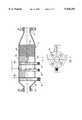
- FIG. 1is an elevational view of one end of the machine with the usual covering doors removed to show the internal construction of the machine.
- FIG. 2is a side elevational view of the machine with the usual doors removed to show the internal construction.
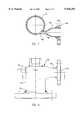
- FIG. 3is an end view of an oxygen mixer.
- FIG. 4is a sectional view taken along lines 4--4 of FIG. 3.
- FIG. 5is a sectional view taken along lines 5--5 of FIG. 3.
- FIG. 6is a side view of the tangential inlet.
- FIG. 7is a sectional view taken along lines 7--7 of FIG. 6.
- FIG. 8is a plan view of the tangential inlet.
- FIG. 9is a sectional view taken along lines 9--9 of FIG. 8.
- FIG. 10is a sectional view taken along lines 10--10 of FIG. 8.
- FIG. 11is an enlarged sectional view of a portion of the vortex forming unit indicated by the circle designated 11 in FIG. 2.
- FIG. 12is an enlarged sectional view of another portion of the vortex forming unit indicated by the circle designated 12 in FIG. 2.
- FIG. 13is a sectional view taken along lines 13--13 of FIG. 12.
- reference character 20generally designates the charging machine of this invention which is adapted to treat a stream of water entering the machine at an inlet 22 and being discharged from the machine through an outlet 24.
- the various components of the machine 20are supported in a generally rectangular frame 25.
- the machine 20comprises an oxygen mixer generally designated by reference character 26; a tangential unit generally designated by reference character 28, and a vortex unit generally designated by reference character 30.
- the stream of water being treatedis directed from the inlet 22 through suitable piping 32, including a 3-way ball valve 34 into the oxygen mixer 26 where gaseous oxygen is mixed with the stream of water.
- the oxygen laden stream of wateris then directed through additional piping 36, including a valve 38, into the tangential unit 28.
- the tangential unit 28performs the function of directing the stream of water in a circular motion, that is, a vortex, downwardly through the vortex unit 30.
- the outer vortex of wateris reversed at the lower end portion of the vortex unit 30 into an inner vortex which moves upwardly through the vortex unit 30 for discharge through the tangential unit 28 and suitable piping 40 to the water outlet 24.
- the oxygen mixer 26is shown in detail in FIGS. 3, 4 and 5.
- the mixer 26comprises a hollow body 42 which is generally rectangular in cross section through the major portion of its length, tapering from the water inlet 44 and then tapered inwardly toward the water outlet 46.
- a pair of rectangular plates 48 and 50are mounted in parallel within the body 42.
- Each of the plates 48 and 50has a plurality of apertures 52 therethrough to disburse oxygen into water flowing around the plates 48 and 50.
- the adjacent ends 54 of the plates 48 and 50are closed by an oxygen tube 56 extending through one sidewall 42a of the body 42 into engagement with the opposite wall 42b of the body 42.
- the oxygen tube 56has a plurality of apertures 58 in one side thereof communicating with the chamber 59 formed by the plates 48 and 50 for directing gaseous oxygen into that chamber.
- Two additional oxygen tubes 60are also extended through the wall 42a of the body 42 into contact with the opposite wall 42b of the body 42.
- Each of the additional oxygen tubes 60has a plurality of apertures 62 therein to feed gaseous oxygen into the chamber 59 formed between the plates 48 and 50. All of the tubes 56 and 60 are connected to a suitable supply of gaseous oxygen (not shown) by means of which oxygen is preliminarily mixed with the stream of water flowing through the body 42 on opposite sides of the plates 48 and 50.
- the opposite ends 64 of the plates 48 and 50are closed by the larger end of a flow diverter 66 formed to have a triangular cross section.
- the diverter 66facilitates a non-turbulent flow of water through the body 42 and thereby facilitates a retention of small oxygen bubbles in the stream of water being discharged from the mixer 26 through the outlet 46. As previously stated, this oxygen-laden water is then directed into the tangential unit 28.
- a bypass line 68(see FIG. 1) is connected to the line conduit 32 by the 3-way ball valve 34.
- the by-pass line 68re-connects with the piping 36 downstream from the mixer 26.
- the incoming stream of watermay be directed either through the oxygen unit 26 or may bypass the oxygen unit 26.
- Suitable flow meters 70 and 72are interposed in the line 32 and the bypass line 68, respectively, to suitably record the flow of water.
- a pair of magnets 75 and 77are suitably supported by straps 79 on opposite sides of the mixer 26 to produce a magnetic field through which the water and oxygen flowing through the mixture 26 are exposed.
- the magnets 75 and 77are arranged with their south poles facing the body 42 of the mixer unit in order to provide a negative magnetic field in the mixer 26.
- the tangential unit 28is shown in detail in FIGS. 6 through 10 and basically comprises a tubular body 74 having an upper end 76 and a lower end 78.
- the upper end 76 of the body 74is closed by a plate 80 (FIG. 9) and a pipe fitting 82 (which receives a tubular member as will be set forth below).
- the inlet 84 of the tangential unithas a suitable flange 86 at its outer end for connection with the inlet pipe 36, and then swedges into a vertically oriented member having a vertically oriented opening 88 therein which mates with an identical vertically oriented opening 90 formed in the sidewall of the body 74.
- the center line of the opening 90is on a tangent with respect to the inner periphery of the body 74, such that water being directed through the inlet 90 will flow around the inner periphery of the tangential unit 74 and then, by virtue of the upper end 76 of the body 74 being closed, the swirling stream of water flows downwardly out through the lower end 78 of the body 74. It will also be noted that the inlet opening 90 is at the upper end portion of the body 74.
- the lower end 78 of the tangential inlet body 74is suitably connected (FIG. 2) to the upper end of a vertically extending tubular member 92. As shown in FIGS. 2 and 11, there is a second tubular member 94 located within the upper end portion of the first tubular member 92. The tubular member 94 is secured in the fitting 82 (FIG. 9) at the upper end of the tangential unit 28 and forms an outlet for water from the vortex unit 30.
- a pair of frusto-conical members 96are secured on the inner tubular member 94 inside the upper end portion of the outer tubular member 92.
- Each of the frusto-conical members 96has an outer surface 98 which tapers downwardly and outwardly, with the outer diameter of the lower end 100 of each frusto-conical member 96 having a diameter less than the inner diameter of the outer tubular member 92.
- the outer tubular member 92is preferably transparent glass. It should also be noted that the inlet opening 90 (FIG. 7) of the tangential unit 28 is arranged such that the stream of water is directed in a clockwise movement around the inner periphery of the tangential body 74 as well as around the inner periphery of the tubular member 92 when viewed in the direction of water flow. For some uses, however, the inlet opening 90 may be arranged to direct the water in a counter clockwise direction.
- the lower end portion 102 of the outer tubular member 92is substantially closed by an obstruction 104.
- the obstruction 104preferably comprises a flat plate having a plurality of apertures 106 therethrough through which oxygen can be introduced into the lower end of the vortex unit 30 and water can be drained from the vortex unit 30 when the unit is stopped.
- a piezoelectric crystal 108is supported on the plate 104 with the lower end 109 of the crystal resting in the opening 105 in such a manner that the crystal 108 will be vibrated by the flow of water through the vortex unit 30.
- the flow of wateris reversed to flow upwardly in the form of an inner vortex inside the outer vortex.
- the upperwardly flowing waterenters the inner tubular member 94 at the upper end of the outer tubular member 92 and is discharged upwardly through the tangential unit 28 into the outlet piping 40 and, thus, to the water outlet 24.
- the crystal 108is supported on the plate 104 by circumferentially spaced rods 110 and a ring 112 attached to the upper ends of the rods 110.
- the lower ends of the rods 110are suitably secured to the plate 104. With this arrangement, as previously indicated, the crystal 108 has room to, and does, vibrate in response to water flowing around it.
- the lower end 102 of the outer tubular member 92 of the vortex unit 30is suitably connected to a "T" 120, also as preferably formed of transparent glass.
- T 120One end 122 of the T 120 is substantially closed, and the opposite end 124 communicates with a drain pipe 126, by means of which water is drained from the machine when the machine is stopped following an operation.
- the entire vortex unit 30is suitably supported by a pipe support stand 128 from an intermediate floor 130 within the frame 25.
- the floor 130is preferably supported by adjustable mounts 132 from the frame 25 in order that the vortex unit 30 can be precisely aligned with the tubular member 92 being vertical. Such orientation improves the control over the formation and positioning of the inner vortex.
- Another oxygen conduit 134extends from the oxygen supply (not shown) through the end 122 of the "T" 120 and to the vicinity of the plate 104. Gaseous oxygen is thereby introduced into the vortex unit 30 essentially at the point of reversal of the stream of water between the outer vortex and the inner vortex, such that bubbles of gaseous oxygen will enter the inner vortex and be forced into the water flowing upwardly in the inner vortex.
- a suitable check valve 136is interposed in the conduit 134 to prevent the back flow of water through the conduit 134 when the machine 20 is shut down.
- a pair of magnets 138are suitably supported on opposite sides of the conduit 134 to produce a magnetic field through which the oxygen flows before it is directed into the lower end of the vortex unit 30. The magnets 138 are preferably located with their south poles on the opposite sides of the conduit 134 to provide a negative magnetic field through which the oxygen passes.
- An assembly of mirrors 140are provided in an arrangement to completely surround the vortex unit 30, with the reflective faces of the mirrors facing inwardly toward the vortex unit 30. It has been found that an assembly of twelve mirror panels can be easily arranged around the vortex unit 30 and supported on suitable slides (not shown) in order that the mirror panels may be moved for access to the vortex unit 30. Further, mirrors 142 and 144 are preferably arranged above and below the vortex unit 30, with the reflective faces thereof facing the vortex unit 30.
- the vortex unit 30 and associated componentsincluding the mirrors 140, 142 and 144, in a subframe 146 by means of slide racks 148 within the outer frame 25.
- the vortex unitwhich includes a substantial amount of glass, can be shipped separately from the remainder of the machine 20 and can be easily removed from the outer frame 25 for service.
- the incoming stream of wateris directed through the piping 32 into and through the mixer 26 where relatively small bubbles of gaseous oxygen are mixed in the water.
- the oxygen laden wateris then directed through the tangential unit 28 where the stream of water is directed in a swirling motion to form an outer vortex which moves downwardly through the outer tubular member 92 of the vortex unit 30.
- this other vortexpreferably moves in a clockwise direction when looking in the direction of movement of the water.
- the flow of wateris reversed to flow upwardly in an inner vortex which is positioned inside the previously mentioned outer vortex.
- additional oxygenmay be introduced through the conduit 134, preferably in bubbles larger than the bubbles produced by the mixer unit 26. The oxygen is thereby fully incorporated in the stream of water discharging through the inner tubular member 94 and out to the water outlet 24.
- the stream of watermay be bypassed around the mixer 26, if desired, and oxygen introduced only at the lower end of the vortex unit 30.
- watermay be introduced through the mixer unit 26 to provide a preliminary mixing of oxygen in the water and no oxygen introduced through the conduit 34 into the lower end portion of the vortex unit 30.
- the use of the magnets 75, 77 and 138result in desirable conditioning of the water passed through the machine 20.
- the water discharged from the machinehas a substantial Zeta potential, found to be highly desirable in many uses of water.
- the crystal 108produces a piezoelectric field through which the water passes in the vortex unit 30 for further conditioning of the water passed through the machine. It has been found that the use of the inner and outer vortexes in the vortex unit 30 produces a substantial amount of radiated energy in the form of a wide band of radio frequencies which is desirably contained within and around the mixer unit 30 by the mirrors 140, 142 and 144.
Landscapes
- Chemical & Material Sciences (AREA)
- Chemical Kinetics & Catalysis (AREA)
- Organic Chemistry (AREA)
- Engineering & Computer Science (AREA)
- Environmental & Geological Engineering (AREA)
- Water Supply & Treatment (AREA)
- Hydrology & Water Resources (AREA)
- Life Sciences & Earth Sciences (AREA)
- Dispersion Chemistry (AREA)
- Health & Medical Sciences (AREA)
- Clinical Laboratory Science (AREA)
- General Health & Medical Sciences (AREA)
- Toxicology (AREA)
- Mechanical Engineering (AREA)
- Physics & Mathematics (AREA)
- Fluid Mechanics (AREA)
- Aeration Devices For Treatment Of Activated Polluted Sludge (AREA)
Abstract
Description
Claims (29)
Priority Applications (4)
| Application Number | Priority Date | Filing Date | Title |
|---|---|---|---|
| US08/867,290US5925292A (en) | 1997-06-02 | 1997-06-02 | Water charging machine |
| AU77093/98AAU7709398A (en) | 1997-06-02 | 1998-05-29 | Water charging machine |
| PCT/US1998/011063WO1998055403A1 (en) | 1997-06-02 | 1998-05-29 | Water charging machine |
| US09/306,500US6076811A (en) | 1997-06-02 | 1999-05-06 | Water charging machine |
Applications Claiming Priority (1)
| Application Number | Priority Date | Filing Date | Title |
|---|---|---|---|
| US08/867,290US5925292A (en) | 1997-06-02 | 1997-06-02 | Water charging machine |
Related Child Applications (1)
| Application Number | Title | Priority Date | Filing Date |
|---|---|---|---|
| US09/306,500DivisionUS6076811A (en) | 1997-06-02 | 1999-05-06 | Water charging machine |
Publications (1)
| Publication Number | Publication Date |
|---|---|
| US5925292Atrue US5925292A (en) | 1999-07-20 |
Family
ID=25349499
Family Applications (2)
| Application Number | Title | Priority Date | Filing Date |
|---|---|---|---|
| US08/867,290Expired - LifetimeUS5925292A (en) | 1997-06-02 | 1997-06-02 | Water charging machine |
| US09/306,500Expired - Fee RelatedUS6076811A (en) | 1997-06-02 | 1999-05-06 | Water charging machine |
Family Applications After (1)
| Application Number | Title | Priority Date | Filing Date |
|---|---|---|---|
| US09/306,500Expired - Fee RelatedUS6076811A (en) | 1997-06-02 | 1999-05-06 | Water charging machine |
Country Status (3)
| Country | Link |
|---|---|
| US (2) | US5925292A (en) |
| AU (1) | AU7709398A (en) |
| WO (1) | WO1998055403A1 (en) |
Cited By (36)
| Publication number | Priority date | Publication date | Assignee | Title |
|---|---|---|---|---|
| WO2001038226A3 (en)* | 1999-11-23 | 2002-01-10 | Dietrich Reichwein | Method and device for the treatment of fluids |
| WO2002026367A3 (en)* | 2000-09-27 | 2002-06-06 | Geir Corp | Apparatus and method for increasing oxygen levels in a liquid |
| US20040046031A1 (en)* | 1990-09-17 | 2004-03-11 | Metrologic Instruments, Inc. | Bar code scanning system with wireless communication links |
| US20040221903A1 (en)* | 2003-05-07 | 2004-11-11 | Dietrich Reichwein | Method and apparatus for the treatment of fluids |
| US7137621B1 (en)* | 2005-06-03 | 2006-11-21 | BAGLEY David | System for super-oxygenating water |
| US20060273045A1 (en)* | 2005-06-03 | 2006-12-07 | BAGLEY David | Method of spinning water and oxygen for producing super-oxygenated and structured water |
| US20060273020A1 (en)* | 2005-06-03 | 2006-12-07 | BAGLEY David | Method for tuning water |
| US20060273042A1 (en)* | 2005-06-03 | 2006-12-07 | BAGLEY David | System for tuning super-oxygenated and structured water to have multiple attributes |
| US20060272990A1 (en)* | 2005-06-03 | 2006-12-07 | BAGLEY David | Apparatus for tuning water |
| US20060272993A1 (en)* | 2005-06-03 | 2006-12-07 | BAGLEY David | Water preconditioning system |
| US20060272991A1 (en)* | 2005-06-03 | 2006-12-07 | BAGLEY David | System for tuning water to target certain pathologies in mammals |
| US20060273043A1 (en)* | 2005-06-03 | 2006-12-07 | BAGLEY David | Method for producing super-oxygenated and structured water |
| EP1749799A1 (en)* | 2005-08-03 | 2007-02-07 | Norbert Stadler | Water treatment apparatus |
| US20080260855A1 (en)* | 2005-06-03 | 2008-10-23 | BAGLEY David | Processed water and therapeutic uses thereof |
| US7654728B2 (en) | 1997-10-24 | 2010-02-02 | Revalesio Corporation | System and method for therapeutic application of dissolved oxygen |
| US20100126916A1 (en)* | 2007-02-23 | 2010-05-27 | Negatron Co., Ltd | Apparatus for manufacturing oxygenated water |
| US20100147690A1 (en)* | 2008-12-16 | 2010-06-17 | Geir Corporation | Oxygenation of a Fluid |
| US7770814B2 (en) | 1997-10-24 | 2010-08-10 | Revalesio Corporation | System and method for irrigating with aerated water |
| US7806584B2 (en) | 1997-10-24 | 2010-10-05 | Revalesio Corporation | Diffuser/emulsifier |
| US7832920B2 (en) | 2006-10-25 | 2010-11-16 | Revalesio Corporation | Mixing device for creating an output mixture by mixing a first material and a second material |
| US7887698B2 (en) | 1997-10-24 | 2011-02-15 | Revalesio Corporation | Diffuser/emulsifier for aquaculture applications |
| US8445546B2 (en) | 2006-10-25 | 2013-05-21 | Revalesio Corporation | Electrokinetically-altered fluids comprising charge-stabilized gas-containing nanostructures |
| US8591957B2 (en) | 2006-10-25 | 2013-11-26 | Revalesio Corporation | Methods of therapeutic treatment of eyes and other human tissues using an oxygen-enriched solution |
| US8609148B2 (en) | 2006-10-25 | 2013-12-17 | Revalesio Corporation | Methods of therapeutic treatment of eyes |
| US8617616B2 (en) | 2006-10-25 | 2013-12-31 | Revalesio Corporation | Methods of wound care and treatment |
| US8784897B2 (en) | 2006-10-25 | 2014-07-22 | Revalesio Corporation | Methods of therapeutic treatment of eyes |
| US8784898B2 (en) | 2006-10-25 | 2014-07-22 | Revalesio Corporation | Methods of wound care and treatment |
| US8815292B2 (en) | 2009-04-27 | 2014-08-26 | Revalesio Corporation | Compositions and methods for treating insulin resistance and diabetes mellitus |
| US8980325B2 (en) | 2008-05-01 | 2015-03-17 | Revalesio Corporation | Compositions and methods for treating digestive disorders |
| US9198929B2 (en) | 2010-05-07 | 2015-12-01 | Revalesio Corporation | Compositions and methods for enhancing physiological performance and recovery time |
| US9492404B2 (en) | 2010-08-12 | 2016-11-15 | Revalesio Corporation | Compositions and methods for treatment of taupathy |
| US9523090B2 (en) | 2007-10-25 | 2016-12-20 | Revalesio Corporation | Compositions and methods for treating inflammation |
| US9745567B2 (en) | 2008-04-28 | 2017-08-29 | Revalesio Corporation | Compositions and methods for treating multiple sclerosis |
| US10125359B2 (en) | 2007-10-25 | 2018-11-13 | Revalesio Corporation | Compositions and methods for treating inflammation |
| US10933388B1 (en) | 2017-07-07 | 2021-03-02 | Jmf Watercraft Design Llc | H20-oxygenation method and oxygenated live well |
| US11357243B2 (en) | 2016-07-04 | 2022-06-14 | Charles Adriano Duvoisin | System and method for the electromagnetic energizing of packaged content and corresponding device |
Families Citing this family (5)
| Publication number | Priority date | Publication date | Assignee | Title |
|---|---|---|---|---|
| AT413020B (en)* | 2002-10-14 | 2005-10-15 | Hochgatterer Manuel | Apparatus for mixing gases and liquids has mixing chamber with axially spaced ribs with sharp edges and domed shaped plates in its center whose widest sections coincide with ribs to form nozzles |
| US20060065987A1 (en)* | 2004-09-30 | 2006-03-30 | Justin Schletz | Two-stage injector-mixer |
| US7624969B2 (en)* | 2004-09-30 | 2009-12-01 | Justin Schletz | Two-stage injector-mixer |
| CN101555842B (en)* | 2009-05-18 | 2013-10-30 | 朱澄清 | Device for magnetizing and separating fluid and detecting and testing fluid magnetizer |
| JP7381180B2 (en)* | 2021-08-23 | 2023-11-15 | 東亜電気工業株式会社 | Micro bubble generation parts and micro bubble generation equipment |
Citations (14)
| Publication number | Priority date | Publication date | Assignee | Title |
|---|---|---|---|---|
| FR1483324A (en)* | 1966-06-14 | 1967-06-02 | Equipment Engineers Inc | Method and apparatus for the treatment of liquids with gases |
| US4147630A (en)* | 1977-09-19 | 1979-04-03 | Laval Claude C | Hydraulic separating device with automatic flow control |
| US4215081A (en)* | 1979-01-24 | 1980-07-29 | Brooks Kirtland H | Liquid aerator |
| US4229389A (en)* | 1979-03-16 | 1980-10-21 | Thompson Marine Corporation | Gas diffuser, aerator, or sparger apparatus |
| US4614596A (en)* | 1985-01-10 | 1986-09-30 | Wyness David K | Apparatus and method for dissolving a gas in an aqueous stream |
| US4981582A (en)* | 1988-01-27 | 1991-01-01 | Virginia Tech Intellectual Properties, Inc. | Process and apparatus for separating fine particles by microbubble flotation together with a process and apparatus for generation of microbubbles |
| US5049320A (en)* | 1990-07-03 | 1991-09-17 | International Environmental Systems, Inc. | Gas dissolving system and method |
| US5326446A (en)* | 1992-07-27 | 1994-07-05 | Larry Binger | Treatment of water with static and radio frequency electromagnetic fields |
| US5391294A (en)* | 1991-03-28 | 1995-02-21 | Codiex (S.N.C.) | Particle separator device with circulation of fluid, with double effect of extraction |
| US5470465A (en)* | 1994-01-28 | 1995-11-28 | Automatic Control Technology Inc. | Vortex system for separating particles from a liquid stream |
| US5472620A (en)* | 1993-09-23 | 1995-12-05 | Exxon Production Research Company | Solid-liquid separation process using at least one polymer and cavitation energy |
| DE4433024A1 (en)* | 1994-09-16 | 1996-05-15 | Bergen Peter Prof Dipl Ing Dr | Process for cleaning water effluent with or without biological action |
| US5705060A (en)* | 1994-03-24 | 1998-01-06 | Gavle Galvan Tryckkarl Ab | Vessel for mixing or separating flowing media |
| US5716520A (en)* | 1995-08-30 | 1998-02-10 | Mason; Elmer B. | Magnetic fluid conditioner |
- 1997
- 1997-06-02USUS08/867,290patent/US5925292A/ennot_activeExpired - Lifetime
- 1998
- 1998-05-29WOPCT/US1998/011063patent/WO1998055403A1/enactiveApplication Filing
- 1998-05-29AUAU77093/98Apatent/AU7709398A/ennot_activeAbandoned
- 1999
- 1999-05-06USUS09/306,500patent/US6076811A/ennot_activeExpired - Fee Related
Patent Citations (14)
| Publication number | Priority date | Publication date | Assignee | Title |
|---|---|---|---|---|
| FR1483324A (en)* | 1966-06-14 | 1967-06-02 | Equipment Engineers Inc | Method and apparatus for the treatment of liquids with gases |
| US4147630A (en)* | 1977-09-19 | 1979-04-03 | Laval Claude C | Hydraulic separating device with automatic flow control |
| US4215081A (en)* | 1979-01-24 | 1980-07-29 | Brooks Kirtland H | Liquid aerator |
| US4229389A (en)* | 1979-03-16 | 1980-10-21 | Thompson Marine Corporation | Gas diffuser, aerator, or sparger apparatus |
| US4614596A (en)* | 1985-01-10 | 1986-09-30 | Wyness David K | Apparatus and method for dissolving a gas in an aqueous stream |
| US4981582A (en)* | 1988-01-27 | 1991-01-01 | Virginia Tech Intellectual Properties, Inc. | Process and apparatus for separating fine particles by microbubble flotation together with a process and apparatus for generation of microbubbles |
| US5049320A (en)* | 1990-07-03 | 1991-09-17 | International Environmental Systems, Inc. | Gas dissolving system and method |
| US5391294A (en)* | 1991-03-28 | 1995-02-21 | Codiex (S.N.C.) | Particle separator device with circulation of fluid, with double effect of extraction |
| US5326446A (en)* | 1992-07-27 | 1994-07-05 | Larry Binger | Treatment of water with static and radio frequency electromagnetic fields |
| US5472620A (en)* | 1993-09-23 | 1995-12-05 | Exxon Production Research Company | Solid-liquid separation process using at least one polymer and cavitation energy |
| US5470465A (en)* | 1994-01-28 | 1995-11-28 | Automatic Control Technology Inc. | Vortex system for separating particles from a liquid stream |
| US5705060A (en)* | 1994-03-24 | 1998-01-06 | Gavle Galvan Tryckkarl Ab | Vessel for mixing or separating flowing media |
| DE4433024A1 (en)* | 1994-09-16 | 1996-05-15 | Bergen Peter Prof Dipl Ing Dr | Process for cleaning water effluent with or without biological action |
| US5716520A (en)* | 1995-08-30 | 1998-02-10 | Mason; Elmer B. | Magnetic fluid conditioner |
Non-Patent Citations (4)
| Title |
|---|
| Exhibit "A". |
| Exhibit "B". |
| Exhibit A .* |
| Exhibit B .* |
Cited By (75)
| Publication number | Priority date | Publication date | Assignee | Title |
|---|---|---|---|---|
| US20040046031A1 (en)* | 1990-09-17 | 2004-03-11 | Metrologic Instruments, Inc. | Bar code scanning system with wireless communication links |
| US7887698B2 (en) | 1997-10-24 | 2011-02-15 | Revalesio Corporation | Diffuser/emulsifier for aquaculture applications |
| US7654728B2 (en) | 1997-10-24 | 2010-02-02 | Revalesio Corporation | System and method for therapeutic application of dissolved oxygen |
| US7770814B2 (en) | 1997-10-24 | 2010-08-10 | Revalesio Corporation | System and method for irrigating with aerated water |
| US7806584B2 (en) | 1997-10-24 | 2010-10-05 | Revalesio Corporation | Diffuser/emulsifier |
| US9034195B2 (en) | 1997-10-24 | 2015-05-19 | Revalesio Corporation | Diffuser/emulsifier for aquaculture applications |
| US8349191B2 (en) | 1997-10-24 | 2013-01-08 | Revalesio Corporation | Diffuser/emulsifier for aquaculture applications |
| US6482318B1 (en)* | 1999-11-23 | 2002-11-19 | Dietrich Reichwein | Method and device for the treatment of fluids |
| WO2001038226A3 (en)* | 1999-11-23 | 2002-01-10 | Dietrich Reichwein | Method and device for the treatment of fluids |
| US20040004042A1 (en)* | 2000-09-27 | 2004-01-08 | Hadley Darrell J | Apparatus and method for increasing oxygen levels in a liquid |
| US6821438B2 (en) | 2000-09-27 | 2004-11-23 | Geir Corporation | Apparatus and method for increasing oxygen levels in a liquid |
| WO2002026367A3 (en)* | 2000-09-27 | 2002-06-06 | Geir Corp | Apparatus and method for increasing oxygen levels in a liquid |
| US20040221903A1 (en)* | 2003-05-07 | 2004-11-11 | Dietrich Reichwein | Method and apparatus for the treatment of fluids |
| US20080260855A1 (en)* | 2005-06-03 | 2008-10-23 | BAGLEY David | Processed water and therapeutic uses thereof |
| US20060273018A1 (en)* | 2005-06-03 | 2006-12-07 | BAGLEY David | Method for making and conditioning super-oxygenated and structured water |
| US20060273020A1 (en)* | 2005-06-03 | 2006-12-07 | BAGLEY David | Method for tuning water |
| US20060273042A1 (en)* | 2005-06-03 | 2006-12-07 | BAGLEY David | System for tuning super-oxygenated and structured water to have multiple attributes |
| US20060272990A1 (en)* | 2005-06-03 | 2006-12-07 | BAGLEY David | Apparatus for tuning water |
| US20060273475A1 (en)* | 2005-06-03 | 2006-12-07 | BAGLEY David | Cone system and structure thereof to produce super-oxygenated and structured water |
| US20060272993A1 (en)* | 2005-06-03 | 2006-12-07 | BAGLEY David | Water preconditioning system |
| US20060273030A1 (en)* | 2005-06-03 | 2006-12-07 | BAGLEY David | Method for preparing oxygenated water with a stable negative oxidation reduction potential (ORP) |
| US20060275447A1 (en)* | 2005-06-03 | 2006-12-07 | BAGLEY David | Processed water and therapeutic uses thereof |
| US20060272991A1 (en)* | 2005-06-03 | 2006-12-07 | BAGLEY David | System for tuning water to target certain pathologies in mammals |
| US20060275474A1 (en)* | 2005-06-03 | 2006-12-07 | BAGLEY David | System for preparing oxygenated water with a stable negative oxidation reduction potential (ORP) |
| US20060275200A1 (en)* | 2005-06-03 | 2006-12-07 | BAGLEY David | Method for structuring oxygen |
| US20060273006A1 (en)* | 2005-06-03 | 2006-12-07 | BAGLEY David | System for enhancing oxygen |
| US20060273024A1 (en)* | 2005-06-03 | 2006-12-07 | BAGLEY David | Processed water and therapeutic uses thereof |
| US20060273476A1 (en)* | 2005-06-03 | 2006-12-07 | BAGLEY David | Method for oxygenating water |
| US20060273029A1 (en)* | 2005-06-03 | 2006-12-07 | BAGLEY David | Method for super-oxygenating water |
| US20060273043A1 (en)* | 2005-06-03 | 2006-12-07 | BAGLEY David | Method for producing super-oxygenated and structured water |
| US20060273473A1 (en)* | 2005-06-03 | 2006-12-07 | BAGLEY David | System for super-oxygenating water |
| US7137621B1 (en)* | 2005-06-03 | 2006-11-21 | BAGLEY David | System for super-oxygenating water |
| US20060273025A1 (en)* | 2005-06-03 | 2006-12-07 | BAGLEY David | Processed water and therapeutic uses thereof |
| US7243910B2 (en)* | 2005-06-03 | 2007-07-17 | BAGLEY David | Cone system and structure thereof to produce super-oxygenated and structured water |
| US7347944B2 (en)* | 2005-06-03 | 2008-03-25 | BAGLEY David | Method for making and conditioning super-oxygenated and structured water |
| US20060272947A1 (en)* | 2005-06-03 | 2006-12-07 | BAGLEY David | System for making and conditioning super-oxygenated and structured water |
| US20060275199A1 (en)* | 2005-06-03 | 2006-12-07 | BAGLEY David | System for producing super-oxygenated and structured water |
| US20060273035A1 (en)* | 2005-06-03 | 2006-12-07 | BAGLEY David | Processed water and therapeutic uses thereof |
| US20060273045A1 (en)* | 2005-06-03 | 2006-12-07 | BAGLEY David | Method of spinning water and oxygen for producing super-oxygenated and structured water |
| US20060275355A1 (en)* | 2005-06-03 | 2006-12-07 | BAGLEY David | Processed water and therapeutic uses thereof |
| WO2007014774A1 (en)* | 2005-08-03 | 2007-02-08 | Norbert Stadler | Water-treatment device |
| EP1749799A1 (en)* | 2005-08-03 | 2007-02-07 | Norbert Stadler | Water treatment apparatus |
| US8410182B2 (en) | 2006-10-25 | 2013-04-02 | Revalesio Corporation | Mixing device |
| US8470893B2 (en) | 2006-10-25 | 2013-06-25 | Revalesio Corporation | Electrokinetically-altered fluids comprising charge-stabilized gas-containing nanostructures |
| US9402803B2 (en) | 2006-10-25 | 2016-08-02 | Revalesio Corporation | Methods of wound care and treatment |
| US8962700B2 (en) | 2006-10-25 | 2015-02-24 | Revalesio Corporation | Electrokinetically-altered fluids comprising charge-stabilized gas-containing nanostructures |
| US9511333B2 (en) | 2006-10-25 | 2016-12-06 | Revalesio Corporation | Ionic aqueous solutions comprising charge-stabilized oxygen-containing nanobubbles |
| US7832920B2 (en) | 2006-10-25 | 2010-11-16 | Revalesio Corporation | Mixing device for creating an output mixture by mixing a first material and a second material |
| US9512398B2 (en) | 2006-10-25 | 2016-12-06 | Revalesio Corporation | Ionic aqueous solutions comprising charge-stabilized oxygen-containing nanobubbles |
| US8445546B2 (en) | 2006-10-25 | 2013-05-21 | Revalesio Corporation | Electrokinetically-altered fluids comprising charge-stabilized gas-containing nanostructures |
| US8449172B2 (en) | 2006-10-25 | 2013-05-28 | Revalesio Corporation | Mixing device for creating an output mixture by mixing a first material and a second material |
| US7919534B2 (en) | 2006-10-25 | 2011-04-05 | Revalesio Corporation | Mixing device |
| US8591957B2 (en) | 2006-10-25 | 2013-11-26 | Revalesio Corporation | Methods of therapeutic treatment of eyes and other human tissues using an oxygen-enriched solution |
| US8597689B2 (en) | 2006-10-25 | 2013-12-03 | Revalesio Corporation | Methods of wound care and treatment |
| US8609148B2 (en) | 2006-10-25 | 2013-12-17 | Revalesio Corporation | Methods of therapeutic treatment of eyes |
| US8617616B2 (en) | 2006-10-25 | 2013-12-31 | Revalesio Corporation | Methods of wound care and treatment |
| US8784897B2 (en) | 2006-10-25 | 2014-07-22 | Revalesio Corporation | Methods of therapeutic treatment of eyes |
| US8784898B2 (en) | 2006-10-25 | 2014-07-22 | Revalesio Corporation | Methods of wound care and treatment |
| US9004743B2 (en) | 2006-10-25 | 2015-04-14 | Revalesio Corporation | Mixing device for creating an output mixture by mixing a first material and a second material |
| US8318009B2 (en)* | 2007-02-23 | 2012-11-27 | Negatron Co., Ltd | Apparatus for manufacturing oxygenated water |
| US20100126916A1 (en)* | 2007-02-23 | 2010-05-27 | Negatron Co., Ltd | Apparatus for manufacturing oxygenated water |
| US10125359B2 (en) | 2007-10-25 | 2018-11-13 | Revalesio Corporation | Compositions and methods for treating inflammation |
| US9523090B2 (en) | 2007-10-25 | 2016-12-20 | Revalesio Corporation | Compositions and methods for treating inflammation |
| US9745567B2 (en) | 2008-04-28 | 2017-08-29 | Revalesio Corporation | Compositions and methods for treating multiple sclerosis |
| US8980325B2 (en) | 2008-05-01 | 2015-03-17 | Revalesio Corporation | Compositions and methods for treating digestive disorders |
| US8409334B2 (en) | 2008-12-16 | 2013-04-02 | Oxy Solutions As | Oxygenation of water for a population of fish |
| US8142550B2 (en) | 2008-12-16 | 2012-03-27 | Oxy Solutions As | Oxygenation of a fluid |
| US20100147690A1 (en)* | 2008-12-16 | 2010-06-17 | Geir Corporation | Oxygenation of a Fluid |
| US9272000B2 (en) | 2009-04-27 | 2016-03-01 | Revalesio Corporation | Compositions and methods for treating insulin resistance and diabetes mellitus |
| US9011922B2 (en) | 2009-04-27 | 2015-04-21 | Revalesio Corporation | Compositions and methods for treating insulin resistance and diabetes mellitus |
| US8815292B2 (en) | 2009-04-27 | 2014-08-26 | Revalesio Corporation | Compositions and methods for treating insulin resistance and diabetes mellitus |
| US9198929B2 (en) | 2010-05-07 | 2015-12-01 | Revalesio Corporation | Compositions and methods for enhancing physiological performance and recovery time |
| US9492404B2 (en) | 2010-08-12 | 2016-11-15 | Revalesio Corporation | Compositions and methods for treatment of taupathy |
| US11357243B2 (en) | 2016-07-04 | 2022-06-14 | Charles Adriano Duvoisin | System and method for the electromagnetic energizing of packaged content and corresponding device |
| US10933388B1 (en) | 2017-07-07 | 2021-03-02 | Jmf Watercraft Design Llc | H20-oxygenation method and oxygenated live well |
Also Published As
| Publication number | Publication date |
|---|---|
| US6076811A (en) | 2000-06-20 |
| AU7709398A (en) | 1998-12-21 |
| WO1998055403A1 (en) | 1998-12-10 |
Similar Documents
| Publication | Publication Date | Title |
|---|---|---|
| US5925292A (en) | Water charging machine | |
| US4773104A (en) | Inflatable bath-pool with means producing massaging fluid jet | |
| US5152464A (en) | Shower filter assembly | |
| US5391294A (en) | Particle separator device with circulation of fluid, with double effect of extraction | |
| FI113748B (en) | Flotation chamber with an injector | |
| CN206799246U (en) | A kind of adjustable efflux aerator of nozzle | |
| US20070158251A1 (en) | Water treatment unit for bottle | |
| JP2003530989A (en) | Differential ejector | |
| US11039630B2 (en) | Gas infusion module | |
| US5091118A (en) | Device for dissolving gasses into liquids | |
| US6709577B2 (en) | High output ozonating apparatus | |
| US5174905A (en) | Apparatus and method for treating water with ozone | |
| NZ211444A (en) | Passive fluid mixing device:orificed tube creates opposed flows in chamber | |
| US6357483B1 (en) | Flow controller | |
| US20070257136A1 (en) | Through-Flow Volume Limiters | |
| US4152262A (en) | Filtration and purification apparatus | |
| TW357239B (en) | Device for the discharge in particular of hot, corrosive liquids, in particular molten salts | |
| US3067951A (en) | Aerator with air inlet at the water outlet | |
| RU2103019C1 (en) | Salt aerosol forming device | |
| KR200292647Y1 (en) | Submersible Aerator | |
| CN209322544U (en) | A kind of normal pressure applied in canned aquatic producing line adds ozone-sterilizing device | |
| JP2915906B1 (en) | Material mixing device using acoustic resonance | |
| US7294260B2 (en) | Aerobic wastewater treatment plant having 3-compartment vessel | |
| JPS6044093A (en) | Aeration apparatus | |
| AU657021B2 (en) | Treatment of liquids |
Legal Events
| Date | Code | Title | Description |
|---|---|---|---|
| AS | Assignment | Owner name:AQUA LIFE CORPORATION, OKLAHOMA Free format text:ASSIGNMENT OF ASSIGNORS INTEREST;ASSIGNOR:ZIESENIS, RANDY T.;REEL/FRAME:008599/0489 Effective date:19970602 | |
| STCF | Information on status: patent grant | Free format text:PATENTED CASE | |
| AS | Assignment | Owner name:ASSEST RECOVERY, INC., OKLAHOMA Free format text:JUDGMENT;ASSIGNOR:AQUA LIFE CORPORATION;REEL/FRAME:011511/0450 Effective date:20000908 | |
| AS | Assignment | Owner name:AQUA ENERGY, INC., BAHAMAS Free format text:ASSIGNMENT OF ASSIGNORS INTEREST;ASSIGNOR:ASSET RECOVERY, LLC;REEL/FRAME:013056/0612 Effective date:20020430 Owner name:ASSET RECOVERY, L.L.C., OKLAHOMA Free format text:ASSIGNMENT OF ASSIGNORS INTEREST;ASSIGNOR:ASSET RECOVERY, INC.;REEL/FRAME:013056/0622 Effective date:20011012 | |
| FPAY | Fee payment | Year of fee payment:4 | |
| REMI | Maintenance fee reminder mailed | ||
| FPAY | Fee payment | Year of fee payment:8 | |
| SULP | Surcharge for late payment | Year of fee payment:7 | |
| FPAY | Fee payment | Year of fee payment:12 |