US5925192A - Dry-cleaning of garments using gas-jet agitation - Google Patents
Dry-cleaning of garments using gas-jet agitationDownload PDFInfo
- Publication number
- US5925192A US5925192AUS08/654,045US65404596AUS5925192AUS 5925192 AUS5925192 AUS 5925192AUS 65404596 AUS65404596 AUS 65404596AUS 5925192 AUS5925192 AUS 5925192A
- Authority
- US
- United States
- Prior art keywords
- gas
- garments
- agitation
- stream
- cleaning
- Prior art date
- Legal status (The legal status is an assumption and is not a legal conclusion. Google has not performed a legal analysis and makes no representation as to the accuracy of the status listed.)
- Expired - Lifetime
Links
- 238000013019agitationMethods0.000titleclaimsabstractdescription78
- 238000005108dry cleaningMethods0.000titleabstractdescription47
- 239000007789gasSubstances0.000claimsabstractdescription137
- 238000000034methodMethods0.000claimsabstractdescription79
- CURLTUGMZLYLDI-UHFFFAOYSA-NCarbon dioxideChemical compoundO=C=OCURLTUGMZLYLDI-UHFFFAOYSA-N0.000claimsabstractdescription72
- 230000008569processEffects0.000claimsabstractdescription59
- 239000004744fabricSubstances0.000claimsabstractdescription50
- 239000002904solventSubstances0.000claimsabstractdescription41
- 229910002092carbon dioxideInorganic materials0.000claimsabstractdescription36
- 239000001569carbon dioxideSubstances0.000claimsabstractdescription36
- IJGRMHOSHXDMSA-UHFFFAOYSA-NAtomic nitrogenChemical compoundN#NIJGRMHOSHXDMSA-UHFFFAOYSA-N0.000claimsabstractdescription19
- 238000007654immersionMethods0.000claimsabstractdescription16
- 229910052757nitrogenInorganic materials0.000claimsabstractdescription8
- 239000003570airSubstances0.000claimsabstractdescription4
- 238000004140cleaningMethods0.000claimsdescription71
- 239000007788liquidSubstances0.000claimsdescription33
- 239000000463materialSubstances0.000claimsdescription19
- 238000001914filtrationMethods0.000claimsdescription8
- 239000000126substanceSubstances0.000claimsdescription8
- 239000002216antistatic agentSubstances0.000claimsdescription2
- 239000003795chemical substances by applicationSubstances0.000claimsdescription2
- 239000002198insoluble materialSubstances0.000claimsdescription2
- 238000004513sizingMethods0.000claimsdescription2
- 239000012756surface treatment agentSubstances0.000claimsdescription2
- 238000005367electrostatic precipitationMethods0.000claims1
- 239000002689soilSubstances0.000abstractdescription66
- 238000012360testing methodMethods0.000description23
- 239000012071phaseSubstances0.000description18
- CYTYCFOTNPOANT-UHFFFAOYSA-NPerchloroethyleneChemical groupClC(Cl)=C(Cl)ClCYTYCFOTNPOANT-UHFFFAOYSA-N0.000description12
- 230000003749cleanlinessEffects0.000description11
- 239000000428dustSubstances0.000description7
- 239000012530fluidSubstances0.000description7
- 239000003599detergentSubstances0.000description6
- 230000002829reductive effectEffects0.000description6
- 230000009471actionEffects0.000description5
- 238000009835boilingMethods0.000description5
- 230000000052comparative effectEffects0.000description4
- 230000007613environmental effectEffects0.000description4
- 239000007787solidSubstances0.000description4
- 230000003247decreasing effectEffects0.000description3
- 238000013461designMethods0.000description3
- 230000007704transitionEffects0.000description3
- 239000000654additiveSubstances0.000description2
- 230000009286beneficial effectEffects0.000description2
- 238000009833condensationMethods0.000description2
- 230000005494condensationEffects0.000description2
- 238000005137deposition processMethods0.000description2
- 238000010586diagramMethods0.000description2
- 229910001873dinitrogenInorganic materials0.000description2
- 230000000694effectsEffects0.000description2
- 239000012717electrostatic precipitatorSubstances0.000description2
- 239000007791liquid phaseSubstances0.000description2
- 238000011068loading methodMethods0.000description2
- 238000012986modificationMethods0.000description2
- 230000004048modificationEffects0.000description2
- 238000002360preparation methodMethods0.000description2
- 230000001105regulatory effectEffects0.000description2
- 238000005507sprayingMethods0.000description2
- 238000003756stirringMethods0.000description2
- 239000000725suspensionSubstances0.000description2
- UOCLXMDMGBRAIB-UHFFFAOYSA-N1,1,1-trichloroethaneChemical compoundCC(Cl)(Cl)ClUOCLXMDMGBRAIB-UHFFFAOYSA-N0.000description1
- AJDIZQLSFPQPEY-UHFFFAOYSA-N1,1,2-TrichlorotrifluoroethaneChemical compoundFC(F)(Cl)C(F)(Cl)ClAJDIZQLSFPQPEY-UHFFFAOYSA-N0.000description1
- OCKGFTQIICXDQW-ZEQRLZLVSA-N5-[(1r)-1-hydroxy-2-[4-[(2r)-2-hydroxy-2-(4-methyl-1-oxo-3h-2-benzofuran-5-yl)ethyl]piperazin-1-yl]ethyl]-4-methyl-3h-2-benzofuran-1-oneChemical compoundC1=C2C(=O)OCC2=C(C)C([C@@H](O)CN2CCN(CC2)C[C@H](O)C2=CC=C3C(=O)OCC3=C2C)=C1OCKGFTQIICXDQW-ZEQRLZLVSA-N0.000description1
- 229920000742CottonPolymers0.000description1
- 230000001133accelerationEffects0.000description1
- 230000002411adverseEffects0.000description1
- 238000013459approachMethods0.000description1
- 230000008901benefitEffects0.000description1
- 230000015572biosynthetic processEffects0.000description1
- 230000008859changeEffects0.000description1
- 231100000481chemical toxicantToxicity0.000description1
- 230000002860competitive effectEffects0.000description1
- 238000001816coolingMethods0.000description1
- 238000004821distillationMethods0.000description1
- 238000001035dryingMethods0.000description1
- 239000000975dyeSubstances0.000description1
- 230000005611electricityEffects0.000description1
- 238000005516engineering processMethods0.000description1
- 239000000284extractSubstances0.000description1
- 238000010438heat treatmentMethods0.000description1
- 230000001939inductive effectEffects0.000description1
- 238000012423maintenanceMethods0.000description1
- JCXJVPUVTGWSNB-UHFFFAOYSA-Nnitrogen dioxideInorganic materialsO=[N]=OJCXJVPUVTGWSNB-UHFFFAOYSA-N0.000description1
- 231100000252nontoxicToxicity0.000description1
- 230000003000nontoxic effectEffects0.000description1
- 239000003921oilSubstances0.000description1
- 239000003208petroleumSubstances0.000description1
- 238000009428plumbingMethods0.000description1
- 238000012545processingMethods0.000description1
- 238000011084recoveryMethods0.000description1
- 230000009467reductionEffects0.000description1
- 238000005057refrigerationMethods0.000description1
- 230000000717retained effectEffects0.000description1
- 238000012552reviewMethods0.000description1
- 239000007921spraySubstances0.000description1
- 238000010186stainingMethods0.000description1
- 230000003068static effectEffects0.000description1
- 238000003860storageMethods0.000description1
- 231100000331toxicToxicity0.000description1
- 230000002588toxic effectEffects0.000description1
- 239000003440toxic substanceSubstances0.000description1
- 238000013022ventingMethods0.000description1
- 238000005406washingMethods0.000description1
- XLYOFNOQVPJJNP-UHFFFAOYSA-NwaterSubstancesOXLYOFNOQVPJJNP-UHFFFAOYSA-N0.000description1
Images

Classifications
- D—TEXTILES; PAPER
- D06—TREATMENT OF TEXTILES OR THE LIKE; LAUNDERING; FLEXIBLE MATERIALS NOT OTHERWISE PROVIDED FOR
- D06F—LAUNDERING, DRYING, IRONING, PRESSING OR FOLDING TEXTILE ARTICLES
- D06F43/00—Dry-cleaning apparatus or methods using volatile solvents
- D—TEXTILES; PAPER
- D06—TREATMENT OF TEXTILES OR THE LIKE; LAUNDERING; FLEXIBLE MATERIALS NOT OTHERWISE PROVIDED FOR
- D06G—MECHANICAL OR PRESSURE CLEANING OF CARPETS, RUGS, SACKS, HIDES, OR OTHER SKIN OR TEXTILE ARTICLES OR FABRICS; TURNING INSIDE-OUT FLEXIBLE TUBULAR OR OTHER HOLLOW ARTICLES
- D06G1/00—Beating, brushing, or otherwise mechanically cleaning or pressure cleaning carpets, rugs, sacks, hides, or other skin or textile articles or fabrics
Definitions
- the present inventionis related generally to a method for dry-cleaning garments or fabrics, and, more particularly, to such method using gas jets to provide agitation that removes insoluble/particulate soils and prevents the re-deposition of such soils.
- a typical dry-cleaning processconsists of a wash, rinse, and drying cycle with solvent recovery.
- the garmentsare loaded into the cleaning drum and immersed in cleaning fluid pumped into the drum from a base tank.
- the soluble soils associated with the garment fabricsdissolve in the cleaning fluid and hence are readily removed.
- insoluble soilsmust be physically dislodged from the fabrics by agitation. Accordingly, the drum tumbles the garments during the wash and rinse cycles to provide the necessary agitation to remove insoluble soil by physical dislodgment.
- insoluble soilalso termed "particulate soil”
- insoluble soilalso termed "particulate soil”
- high solvent flow ratesare generated to transport solvent-containing particulate soil out of the cleaning chamber and through a battery of filters before soil re-deposition occurs.
- the cleaning fluidmust undergo a distillation step to remove the dissolved soils and dyes. The stills are either part of the dry-cleaning machine itself, or self-standing.
- agitation of garments in the cleaning mediumis performed to accelerate removal of soluble soils and is essential in the removal of particulate (insoluble) soils.
- agitationis generally supplied by a rotating drum as described above.
- agitationmay be provided by several means, such as gas bubble/boiling processes, liquid agitation, sonic agitation, and liquid agitation by stirring. Each of these agitation processes are described in the above-mentioned related "Liquid Carbon Dioxide" application.
- liquid agitationinvolves providing liquid solvent inflow through one or more nozzles arranged in such a configuration as to promote the tumbling action through agitation of the cleaning medium and thus the garments contained therewithin.
- Sonic agitationinvolves agitating the garments and fabrics with pressure waves and cavitation using sonic nozzles strategically placed around the internal perforated garment basket.
- liquid agitationmay be provided by simply stirring the cleaning solvent with the use of, for instance, an impeller located under the mesh garment basket. It is also known to use various agitation methods simultaneously to achieve greater agitation.
- liquid carbon dioxidecosts only a fraction of the cost of conventional dry-cleaning solvents (such as PCE) and is preferred in terms of its environmental soundness
- conventional dry-cleaning solventssuch as PCE
- the higher initial capital investment required to implement a liquid carbon dioxide dry-cleaning operationmay prohibit a transition from conventional dry-cleaning solvents.
- an apparatus and methodwhich remove particulate soils from fabrics by agitation with gas jets. While conventional dry-cleaning processes combine agitation and solvent-immersion steps to simultaneously remove both soluble and insoluble soils, the present gas-jet agitation process is conducted separately from the solvent-immersion process. By removing particulate soils in a solvent-free, non-pressurized environment, considerable savings in equipment and operating costs may be realized.
- the method of the inventioncomprises:
- the apparatus of the present inventioncomprises:
- a walled vesselfor receiving gas thereinto, the gas entering the walled vessel in at least one stream, the walled vessel having a side wall, an end wall, and a door, with the side wall defining a cylindrical shape;
- a linerwithin the walled vessel for containing the soiled garments and fabric materials to be cleaned, the liner selected from the group consisting of a perforated liner and a mesh basket, the liner having a cylindrical shape;
- the soiled garments and fabric materialsare placed in the liner within the walled vessel and agitated by the at least one stream of gas, whereupon the insoluble materials are dislodged and removed from the soiled garments and fabric materials.
- gas-jet agitation processBy performing the gas-jet agitation process separately from the solvent-immersion process, solvent operations can be conducted at substantially reduced solvent flow rates. Accordingly, equipment such as pumps and cleaning chambers may be downsized for considerable equipment savings, and energy may be conserved by transporting smaller volumes of solvent. Further, the use of a separate gas-jet agitation process reduces the amount of detergents required for dry cleaning. More specifically, one of the major functions of detergent is to suspend particulate soils in preparation for removal by agitation. The practice of the present invention reduces or obviates the need for detergent to serve as a suspension component. In sum, the gas-jet agitation process of the present invention provides the opportunity for substantial savings in capital and operating costs.
- the gas-jet technology of the present inventionis applicable to any type of dry cleaning process, regardless of the type of dry-cleaning solvent employed.
- the savings in capital and operating costsprove especially beneficial in dry-cleaning processes using dense phase gases as cleaning solvents.
- the capital costs of equipmentsuch as cleaning chambers and pumps are notably higher.
- expensive high-pressure equipmentmay be downsized to reflect lower flow rates, thereby achieving a substantial reduction in capital costs.
- dry-cleaning processes taking advantage of the natural refrigerative properties of dense phase gases to cool equipmentthe need to vent such dense phase gases for cooling purposes is decreased given the lower process heating effects resulting from decreased flow rates and agitation.
- the ability of the present gas-jet agitation system to remove particulate soils from garments and fabricsrivals that of conventional dry-cleaning processes which agitate the garments and fabrics while immersed in solvent.
- the simple design of the apparatus employed in the practice of the inventionhas no moving parts and is relatively inexpensive to fabricate and maintain.
- the gas used as a means of agitationmay be any commonly-available inexpensive gas, such as carbon dioxide, nitrogen, or air, so that the process is environmentally-friendly.
- the method of the present inventionallows the realization of substantial savings in capital and operating costs in exchange for a relatively modest investment.
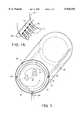
- FIG. 1is a cut-away perspective view illustrating a gas-jet cleaning apparatus constructed in accordance with the present invention and suitable for commercial use;
- FIG. 1Ais an enlarged cut-away view of the nozzle configuration of the gas-jet cleaning apparatus of FIG. 1, illustrating the proper orientation of the nozzles in the practice of the invention;
- FIG. 1Bis a schematic diagram of the supporting apparatus for operating the cleaning chamber of the present invention in a closed loop fashion
- FIG. 1Cis a schematic diagram of the supporting apparatus for operating the cleaning chamber of the present invention in an open loop fashion.
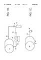
- FIG. 2is a schematic view of the simple gas-jet cleaning apparatus in which the tests of Examples 1-5 were conducted.
- the agitation and solvent-immersion steps of a conventional dry-cleaning processcan be separated for substantial savings in capital costs and operating expenses.
- Gas-jet agitationmay be performed to remove particulate soils from garments and fabrics, while solvent immersion with minimal agitation may be conducted to remove soluble soils in a separate process.
- solvent immersion with minimal agitationmay be conducted to remove soluble soils in a separate process.
- both agitation and solvent-immersion stepsare necessary.
- both types of soilsare present in soiled garments.
- gas-jet agitationis very effective in removing particulate soils (as illustrated by the Examples below)
- solvent-immersionis required to remove soluble soils such as body oils.
- the dry-cleaning processmay consist only of gas-jet agitation, it is more likely that solvent-immersion will be required as well.
- the gas-jet agitation processmay be conducted either before or after a solvent-immersion step.
- a solvent-immersion stepFor garments containing a minimal amount of soluble soils, it is advantageous to perform the gas-jet agitation first. Redeposition of particulate soils is minimized under these conditions.
- it is advantageous to conduct solvent immersion firstsince soluble soils can actually bind particulate soils to fabrics. The removal of soluble soils by immersion in dry cleaning solvents may effectively prepare the particulate soil to be released from the fabric by gas-jet agitation.
- FIG. 1An apparatus representing a preferred embodiment of the gas-jet cleaning chamber of the present invention is portrayed in FIG. 1.
- the fabrics and garments 10 to be cleanedare loaded into a liner 12 within the cleaning chamber 14.
- the cleaning chamber 14is constructed of a solid side wall 16 and a solid end wall 18, such that with the addition of a door (cut away), it completely encloses the liner 12 and garments 10 during processing.
- the liner 12serves to contain the garments as well as to allow the transmittal of gas 20 for purposes of inducing agitation of the garments and transporting soil away from the garments. As such, the liner 12 must have sufficient structure to contain the garments balanced with sufficient holes to allow the transmittal of gas 20.
- the liner 12may be in the form of a perforated drum, but, to simplify maintenance procedures, it is preferably a removable inner basket made of screen mesh. To encourage an effective garment circulation pattern during agitation (as discussed more fully below), the shape of the liner should be such as to promote a continuous tumbling action of the garments 10 into the vortex 21 of the flowing gas stream 20. Accordingly, the liner 12 is preferably constructed in a cylindrical shape. Between the liner 12 and the solid walls 18 of the chamber are gas filtering means 22 designed to remove insoluble particulates from the gas stream 20.
- the filtration means 22may comprise equipment such as, but not limited to, electrostatic precipitators or paper filters. Although not shown in FIG. 1, the door of the cleaning chamber 14 should likewise be equipped with filtration means.
- a gas inlet (or inlets) 24is provided at the side wall 16 of the cleaning chamber 14.
- the gas inlet 24is connected to at least one nozzle 26.
- the nozzle 26should be oriented such that the gas stream 20 is tangent, or slightly inward of tangent relative to the liner 12, and hence sets up a vortex motion within the liner 12.
- a manifold of nozzles 26is provided for more effective agitation of the garments 10. When multiple nozzles 26 are used most of the nozzles should be aligned to contribute to the vortex motion of the gas 20.
- the liner 12must have a set of holes that are aligned with the manifold nozzles 26, such that the flow of incoming gas 20 is unimpeded by the liner 12. These holes may be comprised of perforations in the liner 12 as described above, or may be additional holes specifically located to match the nozzle arrangement.
- the manifold of nozzles 26be centered along the side wall 16 of the cleaning chamber 14 and span the entire length of the liner 12.
- the manifold of nozzles 26is connected via the gas inlet 20 to a gas supply reservoir 40.
- a gas outlet 30is provided in the cleaning chamber 14, preferably at the bottom.
- the fabrics and garments 10 to be cleanedare loaded into the liner 12, whereupon the cleaning chamber is completely enclosed by the placement of a door (not shown).
- a gasis transported into the chamber from the gas supply 40 through the gas inlet 24 and into the manifold of nozzles 26, thereby forming a high speed jet stream.
- the high-speed gassets up convective vortex currents 21 in the enclosed cleaning chamber, as illustrated in FIG. 1.
- the fabricexperiences a momentary acceleration relative to its trailing end as it is moved into the fluid stream 20, resulting in a "stretch".
- the fabric 10relaxes upon reaching the apex of the vortex, whereupon the fabric slides down the wall of the liner 12 into the incoming gas stream 20 to undergo another "stretch and relax" cycle.
- the repeated “stretch and relax” cycles undergone by the garmentsprovide the continuous agitation necessary to mechanically expel particulate soils from the garments. Once expelled, the particulate soils are transported by the gas stream 20 out of the liner 12 and are removed from the gas stream 20 by the filtration means 22 within the cleaning chamber 14.
- the gas streamcreates a continuous tumbling action to agitate the garments 10.
- the filtered gasexits the cleaning chamber 14 via the gas outlet 30.
- the gas used in the gas-jet agitation cleaning processis preferably selected from a group of inexpensive, common non-toxic, non-flammable gases, although any gas would likely be effectual. Examples of such gases include, but are not limited to, air, nitrogen, and carbon dioxide.
- the phase of the gas employedmay be either "dry” (uncompressed) or "dense phase” (compressed to the point of liquification). With an appropriate choice of gas for use in the practice of the invention, the present process can be conducted without the expensive environmental controls necessary when toxic chemicals such as PCE are employed. Only the particulate soil removed from garments 10 by the process of the invention need generate any environmental concern, and one could speculate that soiling substances removed from garments should pose a negligible environmental threat.
- the pressuremust be above the triple point of carbon dioxide (75 psi, or 5.28 Kg/cm 2 ) and the temperature must be equal to the boiling point of carbon dioxide at that pressure.
- the carbon dioxidetakes the form of a liquid spray which can then contact the liner 12. Retaining at least a portion of the carbon dioxide in liquid form can be beneficial. For example, if the liner 12 is covered with particulate soil, the spraying action can wash off the particulate soil into the filtration means 22, thus eliminating the possibility that the particulate soil can be picked up by the garments as re-deposition soil.
- finishing agents commonly employed in the dry cleaning industrysuch as sizing and anti-static agents, may be added.
- the present gas-jet processmay be conducted in either an open loop or closed loop fashion.
- a closed loop manner of operationis preferable if a specific gas such as carbon dioxide or nitrogen is chosen, while an open loop operation is available if air is the gas of choice.
- FIG. 1Bwhich illustrates a closed-loop mode of operation for a dense phase gas operation
- the gas outlet 30is connected to a condenser 34 to condense the gas to a dense phase state in preparation for return to the gas supply tank 40.
- a refrigeration unit 38extracts the heat from the condensation process.
- the pump 36serves to transport the dense phase gas from the condenser 34 to the storage tank 40. Dense phase gas returns to the cleaning chamber 14 through inlet line 28.
- FIG. 1Cwhich illustrates an open-loop mode of operation
- equipmentsuch as a fan or compressor 32 may be used to transport the gas at the pressure needed to form a high speed convective current.
- the choice of equipment used to transport the gas to the cleaning chamber 14does not form part of the invention but should reflect careful consideration of the process operating parameters.
- Typical pressures contemplated for the incoming gas 20 described hereinrange from about 10 to 300 psi (0.7 to 21.1 Kg/cm 2 ), depending on such factors as the amount and weight of the garments 10 to be cleaned and the flow rate of the gas 20. In general, higher pressures will be needed for larger, heavier garments 10 and for loads with a large number of garments 10.
- the pressure of the incoming gas 20should be controlled with a pressure regulator 41, since this pressure will in turn determine the flow rate. Flow rates will accordingly range from 100 liters per minute for a small chamber up to about 10,000 liters per minute for large loads.
- a pressure regulator 41is critical when using a dense phase gas from a compressed gas supply 40, since its pressure is usually substantially higher than is necessary for the gas-jet agitation process.
- the cleaning chamber 14may be operated near atmospheric pressure to simplify its design requirements, the present process is also effective at elevated pressure and may be conducted within the solvent cleaning vessel (not shown), thereby eliminating the labor associated with loading and unloading the vessel.
- the process of the inventioncan be conducted at any temperature that is compatible with the fabric 10 to be cleaned.
- the upper temperature limitis that at which fabric shrinkage starts to occur.
- the lower process temperature for moisture-containing garments 10is 0° C., since formation of ice can trap particulates.
- the temperatureis preferably within the range of about 0° to 50° C. While in general the use of ambient temperature gas is adequate, the temperature of the gas 20 entering the cleaning chamber 14 may be regulated by either a heater or a chiller unit (not shown). In one embodiment, gas-jet agitation can be started at a slightly elevated temperature to reduce moisture content of the garments 10, then the temperature can be allowed to drop below 0° C.
- the gas temperaturecan again be raised back to ambient temperature to prevent excessive condensation on the garments 10 as they are removed from the chamber 14.
- garment moisture regaincan be regulated by the gas-jet temperature and initial moisture content of the garments themselves. Further, this approach is useful in reducing the pressure requirement when boiling liquefied gases are used to rinse the walls of the liner 12 during the gas-jet cleaning to prevent re-deposition, as described above.
- the optimal duration of the agitation processdepends on many factors, such as the extent of soiling of the garments 10, load size, and the gas flow rates employed. However, it is advantageous to minimize the exposure of garments 10 to the agitation generated by high speed gas, which necessarily stresses the fabrics. As illustrated in the Examples below, gas-jet agitation may be effective in as little as 15 seconds, and in any case 5 minutes of agitation is probably sufficient. Most preferably, the duration of agitation ranges from about 1 to 2 minutes. By optimizing the duration of agitation, fabric stress may be reduced and system throughput maximized.
- the minimum "solid wall" surface area of a mesh or perforated liner 12allows particulate soils entrained in the gas stream 20 to pass through, while the garments 10 are retained for further agitation, thereby protecting the garments from re-deposition.
- Examples 1-5were conducted according to the method of the invention in a gas-jet cleaning system 50 depicted schematically in FIG. 2.
- the cleaning chamber 52was constructed from a cylindrical vessel 7.25 inches (18.4 cm) in diameter and 14 inches (36.6 cm) tall.
- a nozzle 54commercially available from Spraying Systems Co. of Wheaton, Ill. as Part No. 12515, was mounted at the center of the cleaning chamber 52 approximately 7 inches (17.8 cm) from the bottom 56 of the cleaning chamber, pointing in an upright direction.
- the gas inlet 58 to the nozzle 54was connected to a tank 60 containing compressed nitrogen, with the pressure regulator 62 set to 200 psi (1.38 Mpa; 14.1 Kg/cm 2 ).
- a ball valve 64was used to start and stop the gas flow.
- a heater 66was provided in the inlet gas line 68 but was not used in these tests.
- a gas outlet 70 at the bottom 56 of the chamber 52was also provided.
- a false bottom 72 made out of screen meshwas placed in the cleaning chamber 52 at a distance of approximately 7 inches (7.8 cm) from the bottom 56 of the cleaning chamber. The false bottom 72 served to keep the fabrics away from the gas outlet 70 and the lower walls 74 of the cleaning chamber 52, as well as to allow the study of re-deposition patterns.
- a thermocouple 76 and a pressure transducer 78were installed to monitor temperature and pressure within the cleaning chamber 52. The cleaning chamber 52 was closed during operation with the placement of a lid 89.
- Examples 6 and 7were conducted for comparative purposes and do not represent the practice of the invention. Both of these tests employed the conventional dry cleaning solvent perchloroethylene (PCE). The methods of agitation used in these tests are described below, but neither test used the gas jets of the present invention for agitation.
- PCEdry cleaning solvent perchloroethylene
- Examples 2A and 2Bwere designed to evaluate the effects of chamber loading, fabric stacking, and lengthier exposure time on the final cleanliness achieved in the practice of the invention.
- the cleanliness resultsare reported in Table 1, above. Although the total amount of dust was substantially higher with this larger load, the final reflectance was essentially unaffected in comparison to Example 1.
- test sampleswere placed on top of the mesh screen 72 and the cleaning chamber 52 was closed.
- the sampleswere exposed to a liquefied carbon dioxide gas jet for one minute at a temperature of about 22° C.
- the source of the liquefied carbon dioxidewas a tank pressurized to 360 psi (2.48 Mpa; 25.3 Kg/cm 2 ), the tank being attached to the inlet gas line 58.
- the gas outlet lineremained open throughout the operation of the gas jet, so that "soil-loaded" liquefied carbon dioxide was eluted as the incoming clean carbon dioxide agitated the fabric test samples.
- the maximum pressure in the cleaning chamberwas 190 psi (1.31 Mpa; 13.4 Kg/cm 2 ), while the temperature dropped from 22° C. to about -30° C. Under these conditions, a portion of the carbon dioxide vaporized from liquid to gas, with the portion that remained liquid reaching the walls of the cleaning chamber 52. After the cleaning chamber was returned to atmospheric pressure the test samples were removed and examined for cleanliness as in Example 1. Cleanliness results are tabulated in Table 1, above.
- Example 3This test was conducted identically to the procedure used in Example 3, except that twenty-six (26) pieces of test fabric were placed in the chamber instead of three, along with one piece of clean fabric used to evaluate re-deposition onto the fabric.
- the cleanliness results for this exampleare reported in Table 1, above. Although the total amount of dust was substantially higher with this larger load, the final reflectance was essentially unaffected.
- test samplewas placed in a one liter jar along with 100 ml of perchloroethylene (PCE) and 1% Staticol (dry cleaning detergent). After closing the lid, the sample was vigorously agitated for 15 min. by an up/down shaking motion at a rate of about 60 times per minute. The sample was then removed from the jar and allowed to air dry. The reflectance of the same was then measured, with the results shown in Table 1, above.
- PCEperchloroethylene
- Staticoldry cleaning detergent
- test samplewas cleaned by a commercial dry cleaning establishment that utilized PCE, water (4%), and a detergent cleaning medium.
- This exampleis included for comparative purposes to dry cleaning processes in which the agitation is conducted on solvent-immersed garments rather than by gas-jet agitation in a solvent-free, low-pressure environment.
- the cleanliness results for this exampleare reported in Table 1, above, which indicates that the initial reflectance for this test sample was inflated compared to other examples, but the final reflectance was essentially the same as that achieved in accordance with the practice of the invention.
- Example 3the dust was concentrated a few inches below the screen mesh 72 and showed a characteristic pattern of having been washed down by the liquid carbon dioxide which had subsequently evaporated upon reaching a warmer portion of the vessel. More specifically, it appeared that about 90% of the dust was below the mesh screen, indicating that the liquid washing technique was effective at reducing the possibility of re-deposition. Furthermore, the clean fabric sample initially added in Example 5 showed only a slight decrease in brightness further confirming minimal re-deposition.
- the method of agitating soiled garments and fabrics with gas jets to dislodge particulate soilsis expected to find use in dry cleaning establishments, and is expected to hasten their transition from conventional toxic dry-cleaning solvents such as PCE to environmentally-friendly solvents such as liquid carbon dioxide.
Landscapes
- Engineering & Computer Science (AREA)
- Textile Engineering (AREA)
- Mechanical Engineering (AREA)
- Treatment Of Fiber Materials (AREA)
- Detergent Compositions (AREA)
- Accessory Of Washing/Drying Machine, Commercial Washing/Drying Machine, Other Washing/Drying Machine (AREA)
Abstract
Description
TABLE 1______________________________________INITIAL AND FINAL REFLECTANCE VALUES ReflectanceExample No. Time (min.) Initial Final______________________________________1 1 2.1 2.72A 1 2.1 <2.62B 3 2.1 >2.63 1 2.1 2.74 0.25 2.1 2.75 1 2.1 2.76 15 2.1 2.77 15 2.4 2.8______________________________________
Claims (13)
Priority Applications (1)
| Application Number | Priority Date | Filing Date | Title |
|---|---|---|---|
| US08/654,045US5925192A (en) | 1994-11-08 | 1996-05-28 | Dry-cleaning of garments using gas-jet agitation |
Applications Claiming Priority (2)
| Application Number | Priority Date | Filing Date | Title |
|---|---|---|---|
| US33560194A | 1994-11-08 | 1994-11-08 | |
| US08/654,045US5925192A (en) | 1994-11-08 | 1996-05-28 | Dry-cleaning of garments using gas-jet agitation |
Related Parent Applications (1)
| Application Number | Title | Priority Date | Filing Date |
|---|---|---|---|
| US33560194AContinuation | 1994-11-08 | 1994-11-08 |
Publications (1)
| Publication Number | Publication Date |
|---|---|
| US5925192Atrue US5925192A (en) | 1999-07-20 |
Family
ID=23312462
Family Applications (2)
| Application Number | Title | Priority Date | Filing Date |
|---|---|---|---|
| US08/592,274Expired - LifetimeUS5651276A (en) | 1994-11-08 | 1996-01-26 | Dry-cleaning of garments using gas-jet agitation |
| US08/654,045Expired - LifetimeUS5925192A (en) | 1994-11-08 | 1996-05-28 | Dry-cleaning of garments using gas-jet agitation |
Family Applications Before (1)
| Application Number | Title | Priority Date | Filing Date |
|---|---|---|---|
| US08/592,274Expired - LifetimeUS5651276A (en) | 1994-11-08 | 1996-01-26 | Dry-cleaning of garments using gas-jet agitation |
Country Status (7)
| Country | Link |
|---|---|
| US (2) | US5651276A (en) |
| EP (1) | EP0711864B1 (en) |
| JP (1) | JP2857087B2 (en) |
| KR (1) | KR0170053B1 (en) |
| CN (1) | CN1069714C (en) |
| DE (1) | DE69521267T2 (en) |
| TW (1) | TW430704B (en) |
Cited By (16)
| Publication number | Priority date | Publication date | Assignee | Title |
|---|---|---|---|---|
| US6114295A (en)* | 1998-05-06 | 2000-09-05 | Lever Brothers Company | Dry cleaning system using densified carbon dioxide and a functionalized surfactant |
| US6117190A (en)* | 1999-08-12 | 2000-09-12 | Raytheon Company | Removing soil from fabric using an ionized flow of pressurized gas |
| US6131421A (en)* | 1995-03-06 | 2000-10-17 | Lever Brothers Company, Division Of Conopco, Inc. | Dry cleaning system using densified carbon dioxide and a surfactant adjunct containing a CO2 -philic and a CO2 -phobic group |
| US6360392B1 (en)* | 1997-12-24 | 2002-03-26 | Alliance Laundry Systems Lll | Liquified gas dry-cleaning machine with improved agitation system |
| US20030056813A1 (en)* | 1992-06-30 | 2003-03-27 | Marshall Mary C. | Apparatus for contaminant removal using natural convection flow and changes in solubility concentrations by temperature |
| US6589592B1 (en) | 1999-09-24 | 2003-07-08 | Micell Technologies | Methods of coating articles using a densified coating system |
| US6666050B2 (en) | 1999-09-24 | 2003-12-23 | Micell Technologies, Inc. | Apparatus for conserving vapor in a carbon dioxide dry cleaning system |
| US20060223980A1 (en)* | 2005-04-01 | 2006-10-05 | Bohnert George W | Method to separate and recover oil and plastic from plastic contaminated with oil |
| US20070228600A1 (en)* | 2005-04-01 | 2007-10-04 | Bohnert George W | Method of making containers from recycled plastic resin |
| US20090178693A1 (en)* | 2003-05-22 | 2009-07-16 | Cool Clean Technologies, Inc. | Extraction process utilzing liquified carbon dioxide |
| US7665227B2 (en) | 2005-12-30 | 2010-02-23 | Whirlpool Corporation | Fabric revitalizing method using low absorbency pads |
| US7735345B2 (en) | 2005-12-30 | 2010-06-15 | Whirlpool Corporation | Automatic fabric treatment appliance with a manual fabric treatment station |
| US20100236580A1 (en)* | 2007-05-15 | 2010-09-23 | Delaurentiis Gary M | METHOD AND SYSTEM FOR REMOVING PCBs FROM SYNTHETIC RESIN MATERIALS |
| US7921578B2 (en)* | 2005-12-30 | 2011-04-12 | Whirlpool Corporation | Nebulizer system for a fabric treatment appliance |
| US8844160B2 (en) | 1997-04-29 | 2014-09-30 | Whirlpool Corporation | Modular fabric revitalizing system |
| WO2017130225A1 (en)* | 2016-01-26 | 2017-08-03 | Jersey Mode S.P.A. | Thermal treatment of textile material |
Families Citing this family (59)
| Publication number | Priority date | Publication date | Assignee | Title |
|---|---|---|---|---|
| DE69521267T2 (en)* | 1994-11-08 | 2002-03-07 | Raytheon Co., Lexington | Dry cleaning clothes using gas jet swirling |
| US5783082A (en)* | 1995-11-03 | 1998-07-21 | University Of North Carolina | Cleaning process using carbon dioxide as a solvent and employing molecularly engineered surfactants |
| US5669251A (en)* | 1996-07-30 | 1997-09-23 | Hughes Aircraft Company | Liquid carbon dioxide dry cleaning system having a hydraulically powered basket |
| US5784905A (en)* | 1996-12-03 | 1998-07-28 | Hughes Electronics | Liquid carbon dioxide cleaning system employing a static dissipating fluid |
| US5928948A (en)* | 1997-03-10 | 1999-07-27 | Steris Corporation | Method for the assessment and validation of cleaning processes |
| US6306564B1 (en) | 1997-05-27 | 2001-10-23 | Tokyo Electron Limited | Removal of resist or residue from semiconductors using supercritical carbon dioxide |
| TW539918B (en) | 1997-05-27 | 2003-07-01 | Tokyo Electron Ltd | Removal of photoresist and photoresist residue from semiconductors using supercritical carbon dioxide process |
| US6500605B1 (en) | 1997-05-27 | 2002-12-31 | Tokyo Electron Limited | Removal of photoresist and residue from substrate using supercritical carbon dioxide process |
| US6216302B1 (en)* | 1997-11-26 | 2001-04-17 | Mve, Inc. | Carbon dioxide dry cleaning system |
| US5904737A (en)* | 1997-11-26 | 1999-05-18 | Mve, Inc. | Carbon dioxide dry cleaning system |
| US6442980B2 (en)* | 1997-11-26 | 2002-09-03 | Chart Inc. | Carbon dioxide dry cleaning system |
| US6070440A (en)* | 1997-12-24 | 2000-06-06 | Raytheon Commercial Laundry Llc | High pressure cleaning vessel with a space saving door opening/closing apparatus |
| US5850747A (en)* | 1997-12-24 | 1998-12-22 | Raytheon Commercial Laundry Llc | Liquified gas dry-cleaning system with pressure vessel temperature compensating compressor |
| US5946945A (en)* | 1997-12-24 | 1999-09-07 | Kegler; Andrew | High pressure liquid/gas storage frame for a pressurized liquid cleaning apparatus |
| US5858107A (en)* | 1998-01-07 | 1999-01-12 | Raytheon Company | Liquid carbon dioxide cleaning using jet edge sonic whistles at low temperature |
| US6098430A (en) | 1998-03-24 | 2000-08-08 | Micell Technologies, Inc. | Cleaning apparatus |
| US6048369A (en)* | 1998-06-03 | 2000-04-11 | North Carolina State University | Method of dyeing hydrophobic textile fibers with colorant materials in supercritical fluid carbon dioxide |
| US5996155A (en)* | 1998-07-24 | 1999-12-07 | Raytheon Company | Process for cleaning, disinfecting, and sterilizing materials using the combination of dense phase gas and ultraviolet radiation |
| US6569210B1 (en)* | 1999-07-14 | 2003-05-27 | Raytheon Company | Gas jet removal of particulated soil from fabric |
| US6085935A (en)* | 1998-08-10 | 2000-07-11 | Alliance Laundry Systems Llc | Pressure vessel door operating apparatus |
| US6277753B1 (en) | 1998-09-28 | 2001-08-21 | Supercritical Systems Inc. | Removal of CMP residue from semiconductors using supercritical carbon dioxide process |
| SE9901403D0 (en)* | 1999-04-20 | 1999-04-20 | Electrolux Ab | Apparatus for cleaning textile articles with a densified liquid processing gas |
| US6349947B1 (en) | 1999-06-23 | 2002-02-26 | Mve, Inc. | High pressure chamber door seal with leak detection system |
| US6334340B1 (en) | 1999-10-08 | 2002-01-01 | Alliance Laundry Systems Llc | Liquified gas dry-cleaning machine with convertible installation configuration |
| US6748960B1 (en) | 1999-11-02 | 2004-06-15 | Tokyo Electron Limited | Apparatus for supercritical processing of multiple workpieces |
| KR100742473B1 (en) | 1999-11-02 | 2007-07-25 | 동경 엘렉트론 주식회사 | Apparatus and method for supercritical treatment of first and second materials |
| US6346126B1 (en)* | 1999-12-02 | 2002-02-12 | Raytheon Company | Acoustic-energy-assisted removal of soil from fabric in a gaseous environment |
| US6261326B1 (en) | 2000-01-13 | 2001-07-17 | North Carolina State University | Method for introducing dyes and other chemicals into a textile treatment system |
| US6248136B1 (en) | 2000-02-03 | 2001-06-19 | Micell Technologies, Inc. | Methods for carbon dioxide dry cleaning with integrated distribution |
| AU2001266556A1 (en)* | 2000-03-24 | 2001-10-03 | The Procter And Gamble Company | Methods and apparatus for particulate removal from fabrics |
| EP1277233A2 (en) | 2000-04-25 | 2003-01-22 | Tokyo Electron Corporation | Method of depositing metal film and metal deposition cluster tool including supercritical drying/cleaning module |
| US6828292B2 (en)* | 2000-06-05 | 2004-12-07 | Procter & Gamble Company | Domestic fabric article refreshment in integrated cleaning and treatment processes |
| US6564591B2 (en)* | 2000-07-21 | 2003-05-20 | Procter & Gamble Company | Methods and apparatus for particulate removal from fabrics |
| US6921456B2 (en) | 2000-07-26 | 2005-07-26 | Tokyo Electron Limited | High pressure processing chamber for semiconductor substrate |
| US6676710B2 (en) | 2000-10-18 | 2004-01-13 | North Carolina State University | Process for treating textile substrates |
| US6536059B2 (en)* | 2001-01-12 | 2003-03-25 | Micell Technologies, Inc. | Pumpless carbon dioxide dry cleaning system |
| JP2006508521A (en) | 2002-02-15 | 2006-03-09 | 東京エレクトロン株式会社 | Drying of resist using solvent bath and supercritical CO2 |
| US6924086B1 (en) | 2002-02-15 | 2005-08-02 | Tokyo Electron Limited | Developing photoresist with supercritical fluid and developer |
| EP1481284A4 (en) | 2002-03-04 | 2006-10-25 | Tokyo Electron Ltd | METHOD FOR PASSIVATING LOW DIELECTRIC MATERIALS IN WELDING PROCESSING |
| US7387868B2 (en) | 2002-03-04 | 2008-06-17 | Tokyo Electron Limited | Treatment of a dielectric layer using supercritical CO2 |
| US7169540B2 (en) | 2002-04-12 | 2007-01-30 | Tokyo Electron Limited | Method of treatment of porous dielectric films to reduce damage during cleaning |
| US6868701B2 (en)* | 2002-06-14 | 2005-03-22 | Yong Mi Lee | Washing machine equipped with means for generating microbubbles of air |
| US7163380B2 (en) | 2003-07-29 | 2007-01-16 | Tokyo Electron Limited | Control of fluid flow in the processing of an object with a fluid |
| US7250374B2 (en) | 2004-06-30 | 2007-07-31 | Tokyo Electron Limited | System and method for processing a substrate using supercritical carbon dioxide processing |
| US7307019B2 (en) | 2004-09-29 | 2007-12-11 | Tokyo Electron Limited | Method for supercritical carbon dioxide processing of fluoro-carbon films |
| US7491036B2 (en) | 2004-11-12 | 2009-02-17 | Tokyo Electron Limited | Method and system for cooling a pump |
| US7434590B2 (en) | 2004-12-22 | 2008-10-14 | Tokyo Electron Limited | Method and apparatus for clamping a substrate in a high pressure processing system |
| US7140393B2 (en) | 2004-12-22 | 2006-11-28 | Tokyo Electron Limited | Non-contact shuttle valve for flow diversion in high pressure systems |
| NL1028037C2 (en)* | 2005-01-14 | 2006-07-17 | Stork Prints Bv | Device for treating parts of a substrate with a supercritical or near-critical treatment medium under high pressure or batchwise. |
| US7435447B2 (en) | 2005-02-15 | 2008-10-14 | Tokyo Electron Limited | Method and system for determining flow conditions in a high pressure processing system |
| US7291565B2 (en) | 2005-02-15 | 2007-11-06 | Tokyo Electron Limited | Method and system for treating a substrate with a high pressure fluid using fluorosilicic acid |
| US7550075B2 (en) | 2005-03-23 | 2009-06-23 | Tokyo Electron Ltd. | Removal of contaminants from a fluid |
| US7399708B2 (en) | 2005-03-30 | 2008-07-15 | Tokyo Electron Limited | Method of treating a composite spin-on glass/anti-reflective material prior to cleaning |
| US7442636B2 (en) | 2005-03-30 | 2008-10-28 | Tokyo Electron Limited | Method of inhibiting copper corrosion during supercritical CO2 cleaning |
| US7789971B2 (en) | 2005-05-13 | 2010-09-07 | Tokyo Electron Limited | Treatment of substrate using functionalizing agent in supercritical carbon dioxide |
| US7524383B2 (en) | 2005-05-25 | 2009-04-28 | Tokyo Electron Limited | Method and system for passivating a processing chamber |
| JP4832218B2 (en)* | 2006-08-31 | 2011-12-07 | 三洋電機株式会社 | Dry cleaning device |
| US7637129B2 (en)* | 2007-10-04 | 2009-12-29 | Sheng-Ming Wang | Air jet pressurized clothes washing machine |
| US8302431B2 (en)* | 2009-06-03 | 2012-11-06 | Green Solution, Inc. | Method and apparatus for using steam in a commercial laundry machine as an environmentally-friendly replacement of conventional dry cleaning or wet cleaning processes |
Citations (33)
| Publication number | Priority date | Publication date | Assignee | Title |
|---|---|---|---|---|
| US28469A (en)* | 1860-05-29 | Improvement in horseshoes | ||
| US1616132A (en)* | 1925-11-12 | 1927-02-01 | Fountain William H La | Rotary dusting machine |
| US1714223A (en)* | 1928-03-26 | 1929-05-21 | Frank M Fagundes Jr | Deodorizing dust wheel |
| US2029117A (en)* | 1933-04-15 | 1936-01-28 | American Laundry Mach Co | Drying machine |
| US2729844A (en)* | 1951-12-11 | 1956-01-10 | Altman & Co B | Machine for dust cleaning garments |
| US3504510A (en)* | 1967-10-02 | 1970-04-07 | Daniel Freze | Drapery and fur cleaning machine |
| US3577215A (en)* | 1969-02-03 | 1971-05-04 | Means & Co F W | Dry cleaning process |
| US3600731A (en)* | 1967-12-13 | 1971-08-24 | Ludvig Svensson Holland Nv | Method for treating textiles |
| US3785123A (en)* | 1972-02-07 | 1974-01-15 | W Leith | Rotating concentric {37 homogeneous turbulence{38 {0 fabric bag gas cleaner method |
| US3816070A (en)* | 1968-12-31 | 1974-06-11 | R Candor | Method and apparatus for treating porous material with fluid |
| US3906756A (en)* | 1974-01-15 | 1975-09-23 | Aubra N Bone | Drapery and sheet material cleaning machine |
| US4077770A (en)* | 1976-07-15 | 1978-03-07 | Rouvellat Richard A | Textile cleaning process including soil-repellent finish |
| US4151139A (en)* | 1971-08-25 | 1979-04-24 | Sandoz Ltd. | Water soluble polyglycol diepoxide-polyamine amide reaction products as antistatic agents |
| US4223065A (en)* | 1977-11-08 | 1980-09-16 | Unitika Ltd | Anti-graying fabrics of synthetic polyester fibers and process for producing same |
| US4314805A (en)* | 1979-10-29 | 1982-02-09 | Mcknight Eugene A | Laundry process and method for treating textiles |
| US4319890A (en)* | 1978-04-05 | 1982-03-16 | Teller Environmental Systems, Inc. | Dry impact capture of aerosol particulates |
| US4443111A (en)* | 1981-06-23 | 1984-04-17 | Andre Minaire | Installation for washing vegetables, fruits or similar products |
| US4727734A (en)* | 1984-05-17 | 1988-03-01 | Masao Kanazawa | Ultrasonic washing machine |
| US5013366A (en)* | 1988-12-07 | 1991-05-07 | Hughes Aircraft Company | Cleaning process using phase shifting of dense phase gases |
| US5118173A (en)* | 1991-01-31 | 1992-06-02 | Deborah Proctor | Laundry hamper assembly for the segregated collection and storage of soiled laundry |
| US5212969A (en)* | 1988-02-23 | 1993-05-25 | Mitsubishi Jukogyo Kabushiki Kaisha | Drum type washing apparatus and method of processing the wash using said apparatus |
| US5219371A (en)* | 1992-03-27 | 1993-06-15 | Shim Kyong S | Dry cleaning system and method having steam injection |
| US5220813A (en)* | 1988-06-13 | 1993-06-22 | Chen Haw Renn | Unified washing-drying machine |
| US5267455A (en)* | 1992-07-13 | 1993-12-07 | The Clorox Company | Liquid/supercritical carbon dioxide dry cleaning system |
| US5279615A (en)* | 1991-06-14 | 1994-01-18 | The Clorox Company | Method and composition using densified carbon dioxide and cleaning adjunct to clean fabrics |
| US5309587A (en)* | 1992-01-17 | 1994-05-10 | Fierro James V | Industrial rag cleaning process |
| US5316591A (en)* | 1992-08-10 | 1994-05-31 | Hughes Aircraft Company | Cleaning by cavitation in liquefied gas |
| US5339844A (en)* | 1992-08-10 | 1994-08-23 | Hughes Aircraft Company | Low cost equipment for cleaning using liquefiable gases |
| US5370740A (en)* | 1993-10-01 | 1994-12-06 | Hughes Aircraft Company | Chemical decomposition by sonication in liquid carbon dioxide |
| US5456759A (en)* | 1992-08-10 | 1995-10-10 | Hughes Aircraft Company | Method using megasonic energy in liquefied gases |
| US5467492A (en)* | 1994-04-29 | 1995-11-21 | Hughes Aircraft Company | Dry-cleaning of garments using liquid carbon dioxide under agitation as cleaning medium |
| US5486236A (en)* | 1994-05-06 | 1996-01-23 | Hughes Aircraft Company | Accelerated extraction of rolled materials |
| US5651276A (en)* | 1994-11-08 | 1997-07-29 | Hughes Aircraft Company | Dry-cleaning of garments using gas-jet agitation |
Family Cites Families (18)
| Publication number | Priority date | Publication date | Assignee | Title |
|---|---|---|---|---|
| US2431246A (en)* | 1946-01-25 | 1947-11-18 | Edwin R Hallanan | Domestic washing machine for clothes, dishes, and the like |
| US2575039A (en)* | 1949-08-09 | 1951-11-13 | Barnes John | Washing machine |
| FR1290998A (en)* | 1961-03-09 | 1962-04-20 | Method of cleaning, in particular for clothes and similar objects, and apparatus for carrying out this method | |
| FR1313500A (en)* | 1962-02-02 | 1966-04-22 | Automatic machine for threshing and dusting of furs, clothing or other articles | |
| US3173279A (en)* | 1962-02-13 | 1965-03-16 | Tarsey Alexandre Rolf | Mechanical cleaning device |
| US3293890A (en)* | 1965-05-14 | 1966-12-27 | Valcox Corp | Aspir-jet washer |
| US3447174A (en)* | 1967-05-03 | 1969-06-03 | Robert R Candor | Laundry apparatus or the like |
| FR2036592A5 (en)* | 1969-03-26 | 1970-12-24 | Champeau Andre | |
| US3722235A (en)* | 1971-01-07 | 1973-03-27 | Alloy Fabrications Inc | Method and apparatus for dying textiles |
| JPS6045399A (en)* | 1983-08-22 | 1985-03-11 | 株式会社東京洗染機械製作所 | Washing method by dry cleaning machine |
| JPH0763687B2 (en)* | 1986-06-11 | 1995-07-12 | 株式会社オ−・エイチ・エル | Article cleaning method and device |
| US4941333A (en)* | 1989-01-31 | 1990-07-17 | Levi Strauss & Co. | Centrifugally draining single drum washing machine |
| DE3904514C2 (en)* | 1989-02-15 | 1999-03-11 | Oeffentliche Pruefstelle Und T | Process for cleaning or washing parts of clothing or the like |
| JPH0461685U (en)* | 1990-09-28 | 1992-05-27 | ||
| RU1813578C (en)* | 1990-11-30 | 1993-05-07 | Московский Текстильный Институт Им.А.Н.Косыгина | Aerodynamic cyclone separator |
| KR950007050B1 (en)* | 1991-01-12 | 1995-06-30 | 대우전자주식회사 | Washing Machine with Bubble Generator and Washing Method of Laundry by Bubble |
| US5161394A (en)* | 1991-07-26 | 1992-11-10 | William Felzer | Washing machine |
| JPH05329294A (en)* | 1992-05-29 | 1993-12-14 | Sanyo Electric Co Ltd | Clothes cleaning method |
- 1995
- 1995-10-09DEDE69521267Tpatent/DE69521267T2/ennot_activeExpired - Lifetime
- 1995-10-09EPEP95115890Apatent/EP0711864B1/ennot_activeExpired - Lifetime
- 1995-11-07CNCN95118757Apatent/CN1069714C/ennot_activeExpired - Fee Related
- 1995-11-08JPJP7289706Apatent/JP2857087B2/ennot_activeExpired - Fee Related
- 1995-11-08KRKR1019950040202Apatent/KR0170053B1/ennot_activeExpired - Fee Related
- 1996
- 1996-01-26USUS08/592,274patent/US5651276A/ennot_activeExpired - Lifetime
- 1996-05-28USUS08/654,045patent/US5925192A/ennot_activeExpired - Lifetime
- 1998
- 1998-09-02TWTW087114602Apatent/TW430704B/ennot_activeIP Right Cessation
Patent Citations (34)
| Publication number | Priority date | Publication date | Assignee | Title |
|---|---|---|---|---|
| US28469A (en)* | 1860-05-29 | Improvement in horseshoes | ||
| US1616132A (en)* | 1925-11-12 | 1927-02-01 | Fountain William H La | Rotary dusting machine |
| US1714223A (en)* | 1928-03-26 | 1929-05-21 | Frank M Fagundes Jr | Deodorizing dust wheel |
| US2029117A (en)* | 1933-04-15 | 1936-01-28 | American Laundry Mach Co | Drying machine |
| US2729844A (en)* | 1951-12-11 | 1956-01-10 | Altman & Co B | Machine for dust cleaning garments |
| US3504510A (en)* | 1967-10-02 | 1970-04-07 | Daniel Freze | Drapery and fur cleaning machine |
| US3600731A (en)* | 1967-12-13 | 1971-08-24 | Ludvig Svensson Holland Nv | Method for treating textiles |
| US3816070A (en)* | 1968-12-31 | 1974-06-11 | R Candor | Method and apparatus for treating porous material with fluid |
| US3577215A (en)* | 1969-02-03 | 1971-05-04 | Means & Co F W | Dry cleaning process |
| USRE28469E (en) | 1969-02-03 | 1975-07-08 | Dry cleaning process | |
| US4151139A (en)* | 1971-08-25 | 1979-04-24 | Sandoz Ltd. | Water soluble polyglycol diepoxide-polyamine amide reaction products as antistatic agents |
| US3785123A (en)* | 1972-02-07 | 1974-01-15 | W Leith | Rotating concentric {37 homogeneous turbulence{38 {0 fabric bag gas cleaner method |
| US3906756A (en)* | 1974-01-15 | 1975-09-23 | Aubra N Bone | Drapery and sheet material cleaning machine |
| US4077770A (en)* | 1976-07-15 | 1978-03-07 | Rouvellat Richard A | Textile cleaning process including soil-repellent finish |
| US4223065A (en)* | 1977-11-08 | 1980-09-16 | Unitika Ltd | Anti-graying fabrics of synthetic polyester fibers and process for producing same |
| US4319890A (en)* | 1978-04-05 | 1982-03-16 | Teller Environmental Systems, Inc. | Dry impact capture of aerosol particulates |
| US4314805A (en)* | 1979-10-29 | 1982-02-09 | Mcknight Eugene A | Laundry process and method for treating textiles |
| US4443111A (en)* | 1981-06-23 | 1984-04-17 | Andre Minaire | Installation for washing vegetables, fruits or similar products |
| US4727734A (en)* | 1984-05-17 | 1988-03-01 | Masao Kanazawa | Ultrasonic washing machine |
| US5212969A (en)* | 1988-02-23 | 1993-05-25 | Mitsubishi Jukogyo Kabushiki Kaisha | Drum type washing apparatus and method of processing the wash using said apparatus |
| US5220813A (en)* | 1988-06-13 | 1993-06-22 | Chen Haw Renn | Unified washing-drying machine |
| US5013366A (en)* | 1988-12-07 | 1991-05-07 | Hughes Aircraft Company | Cleaning process using phase shifting of dense phase gases |
| US5118173A (en)* | 1991-01-31 | 1992-06-02 | Deborah Proctor | Laundry hamper assembly for the segregated collection and storage of soiled laundry |
| US5279615A (en)* | 1991-06-14 | 1994-01-18 | The Clorox Company | Method and composition using densified carbon dioxide and cleaning adjunct to clean fabrics |
| US5309587A (en)* | 1992-01-17 | 1994-05-10 | Fierro James V | Industrial rag cleaning process |
| US5219371A (en)* | 1992-03-27 | 1993-06-15 | Shim Kyong S | Dry cleaning system and method having steam injection |
| US5267455A (en)* | 1992-07-13 | 1993-12-07 | The Clorox Company | Liquid/supercritical carbon dioxide dry cleaning system |
| US5316591A (en)* | 1992-08-10 | 1994-05-31 | Hughes Aircraft Company | Cleaning by cavitation in liquefied gas |
| US5339844A (en)* | 1992-08-10 | 1994-08-23 | Hughes Aircraft Company | Low cost equipment for cleaning using liquefiable gases |
| US5456759A (en)* | 1992-08-10 | 1995-10-10 | Hughes Aircraft Company | Method using megasonic energy in liquefied gases |
| US5370740A (en)* | 1993-10-01 | 1994-12-06 | Hughes Aircraft Company | Chemical decomposition by sonication in liquid carbon dioxide |
| US5467492A (en)* | 1994-04-29 | 1995-11-21 | Hughes Aircraft Company | Dry-cleaning of garments using liquid carbon dioxide under agitation as cleaning medium |
| US5486236A (en)* | 1994-05-06 | 1996-01-23 | Hughes Aircraft Company | Accelerated extraction of rolled materials |
| US5651276A (en)* | 1994-11-08 | 1997-07-29 | Hughes Aircraft Company | Dry-cleaning of garments using gas-jet agitation |
Cited By (41)
| Publication number | Priority date | Publication date | Assignee | Title |
|---|---|---|---|---|
| US20030056813A1 (en)* | 1992-06-30 | 2003-03-27 | Marshall Mary C. | Apparatus for contaminant removal using natural convection flow and changes in solubility concentrations by temperature |
| US6799587B2 (en)* | 1992-06-30 | 2004-10-05 | Southwest Research Institute | Apparatus for contaminant removal using natural convection flow and changes in solubility concentrations by temperature |
| US6461387B1 (en) | 1995-03-06 | 2002-10-08 | Lever Brothers Company, Division Of Conopco, Inc. | Dry cleaning system with low HLB surfactant |
| US6131421A (en)* | 1995-03-06 | 2000-10-17 | Lever Brothers Company, Division Of Conopco, Inc. | Dry cleaning system using densified carbon dioxide and a surfactant adjunct containing a CO2 -philic and a CO2 -phobic group |
| US6148644A (en)* | 1995-03-06 | 2000-11-21 | Lever Brothers Company, Division Of Conopco, Inc. | Dry cleaning system using densified carbon dioxide and a surfactant adjunct |
| US6299652B1 (en) | 1995-03-06 | 2001-10-09 | Lever Brothers Company, Division Of Conopco, Inc. | Method of dry cleaning using densified carbon dioxide and a surfactant |
| US8844160B2 (en) | 1997-04-29 | 2014-09-30 | Whirlpool Corporation | Modular fabric revitalizing system |
| US6360392B1 (en)* | 1997-12-24 | 2002-03-26 | Alliance Laundry Systems Lll | Liquified gas dry-cleaning machine with improved agitation system |
| US6114295A (en)* | 1998-05-06 | 2000-09-05 | Lever Brothers Company | Dry cleaning system using densified carbon dioxide and a functionalized surfactant |
| AU750923B2 (en)* | 1999-08-12 | 2002-08-01 | Raytheon Company | Removing soil from fabric using an ionized flow of pressurized gas |
| RU2194813C1 (en)* | 1999-08-12 | 2002-12-20 | Рэйтеон Компани | Material cleaning method (versions) and apparatus |
| WO2001012893A1 (en)* | 1999-08-12 | 2001-02-22 | Raytheon Company | Removing soil from fabric using an ionized flow of pressurized gas |
| US6117190A (en)* | 1999-08-12 | 2000-09-12 | Raytheon Company | Removing soil from fabric using an ionized flow of pressurized gas |
| US20030182731A1 (en)* | 1999-09-24 | 2003-10-02 | Worm Steve Lee | Cleaning apparatus having multiple wash tanks for carbon dioxide dry cleaning and methods of using same |
| US20040083555A1 (en)* | 1999-09-24 | 2004-05-06 | Brainard David E. | Apparatus for conserving vapor in a carbon dioxide dry cleaning system |
| US6795991B2 (en) | 1999-09-24 | 2004-09-28 | Micell Technologies | Apparatus for conserving vapor in a carbon dioxide dry cleaning system |
| US6666050B2 (en) | 1999-09-24 | 2003-12-23 | Micell Technologies, Inc. | Apparatus for conserving vapor in a carbon dioxide dry cleaning system |
| US20040255393A1 (en)* | 1999-09-24 | 2004-12-23 | Brainard David E. | Apparatus and methods for conserving vapor in a carbon dioxide dry cleaning system |
| US6921420B2 (en) | 1999-09-24 | 2005-07-26 | Micell Technologies | Apparatus and methods for conserving vapor in a carbon dioxide dry cleaning system |
| US7114508B2 (en) | 1999-09-24 | 2006-10-03 | Micell Technologies | Cleaning apparatus having multiple wash tanks for carbon dioxide dry cleaning and methods of using same |
| US20070017557A1 (en)* | 1999-09-24 | 2007-01-25 | Micell Technologies | Cleaning apparatus having multiple wash tanks for carbon dioxide dry cleaning and methods of using same |
| US6589592B1 (en) | 1999-09-24 | 2003-07-08 | Micell Technologies | Methods of coating articles using a densified coating system |
| US7915379B2 (en) | 2003-05-22 | 2011-03-29 | Cool Clean Technologies, Inc. | Extraction process utilzing liquified carbon dioxide |
| US20090178693A1 (en)* | 2003-05-22 | 2009-07-16 | Cool Clean Technologies, Inc. | Extraction process utilzing liquified carbon dioxide |
| US20060223980A1 (en)* | 2005-04-01 | 2006-10-05 | Bohnert George W | Method to separate and recover oil and plastic from plastic contaminated with oil |
| US20060281896A1 (en)* | 2005-04-01 | 2006-12-14 | Honeywell Federal Manufacturing & Technologies | System for removing contaminants from plastic resin |
| US20070228600A1 (en)* | 2005-04-01 | 2007-10-04 | Bohnert George W | Method of making containers from recycled plastic resin |
| US7452962B2 (en) | 2005-04-01 | 2008-11-18 | Honeywell Federal Manufacturing & Technologies, Llc | Method of removing contaminants from plastic resins |
| US7462685B2 (en) | 2005-04-01 | 2008-12-09 | Honeywell Federal Manufacturing & Technologies, Llc | Method for removing contaminants from plastic resin |
| US7470766B2 (en) | 2005-04-01 | 2008-12-30 | Honeywell Federal Manufacturing & Technologies, Llc | Method for removing contaminants from plastic resin |
| US7473759B2 (en) | 2005-04-01 | 2009-01-06 | Honeywell Federal Manufacturing & Technologies, Llc | Apparatus and method for removing solvent from carbon dioxide in resin recycling system |
| US7473758B2 (en) | 2005-04-01 | 2009-01-06 | Honeywell Federal Manufacturing & Technologies, Llc | Solvent cleaning system and method for removing contaminants from solvent used in resin recycling |
| US20060287213A1 (en)* | 2005-04-01 | 2006-12-21 | Honeywell Federal Manufacturing & Technologies | A solvent cleaning system for removing contaminants from a solvent used in resin recycling |
| US20060219276A1 (en)* | 2005-04-01 | 2006-10-05 | Bohnert George W | Improved method to separate and recover oil and plastic from plastic contaminated with oil |
| US7253253B2 (en)* | 2005-04-01 | 2007-08-07 | Honeywell Federal Manufacturing & Technology, Llc | Method of removing contaminants from plastic resins |
| US7838628B2 (en) | 2005-04-01 | 2010-11-23 | Honeywell Federal Manufacturing & Technologies, Llc | System for removing contaminants from plastic resin |
| US7735345B2 (en) | 2005-12-30 | 2010-06-15 | Whirlpool Corporation | Automatic fabric treatment appliance with a manual fabric treatment station |
| US7921578B2 (en)* | 2005-12-30 | 2011-04-12 | Whirlpool Corporation | Nebulizer system for a fabric treatment appliance |
| US7665227B2 (en) | 2005-12-30 | 2010-02-23 | Whirlpool Corporation | Fabric revitalizing method using low absorbency pads |
| US20100236580A1 (en)* | 2007-05-15 | 2010-09-23 | Delaurentiis Gary M | METHOD AND SYSTEM FOR REMOVING PCBs FROM SYNTHETIC RESIN MATERIALS |
| WO2017130225A1 (en)* | 2016-01-26 | 2017-08-03 | Jersey Mode S.P.A. | Thermal treatment of textile material |
Also Published As
| Publication number | Publication date |
|---|---|
| EP0711864A1 (en) | 1996-05-15 |
| TW430704B (en) | 2001-04-21 |
| KR960018053A (en) | 1996-06-17 |
| US5651276A (en) | 1997-07-29 |
| JPH08206393A (en) | 1996-08-13 |
| CN1069714C (en) | 2001-08-15 |
| DE69521267D1 (en) | 2001-07-19 |
| EP0711864B1 (en) | 2001-06-13 |
| CN1132284A (en) | 1996-10-02 |
| JP2857087B2 (en) | 1999-02-10 |
| DE69521267T2 (en) | 2002-03-07 |
| KR0170053B1 (en) | 1999-01-15 |
Similar Documents
| Publication | Publication Date | Title |
|---|---|---|
| US5925192A (en) | Dry-cleaning of garments using gas-jet agitation | |
| US5881577A (en) | Pressure-swing absorption based cleaning methods and systems | |
| EP0679753B1 (en) | Dry-cleaning of garments using liquid carbon dioxide under agitation as cleaning medium | |
| US5219371A (en) | Dry cleaning system and method having steam injection | |
| US5412958A (en) | Liquid/supercritical carbon dioxide/dry cleaning system | |
| US6045588A (en) | Non-aqueous washing apparatus and method | |
| EP1290264B1 (en) | Home laundry method | |
| US6442980B2 (en) | Carbon dioxide dry cleaning system | |
| US6736859B2 (en) | Cleaning system utilizing an organic cleaning solvent and a pressurized fluid solvent | |
| AU2001266721A1 (en) | Home laundry method | |
| US6051421A (en) | Continuous processing apparatus and method for cleaning articles with liquified compressed gaseous solvents | |
| US6536059B2 (en) | Pumpless carbon dioxide dry cleaning system | |
| KR100395606B1 (en) | Gas jet removal of particulated soil from fabric | |
| AU8021700B2 (en) |
Legal Events
| Date | Code | Title | Description |
|---|---|---|---|
| STCF | Information on status: patent grant | Free format text:PATENTED CASE | |
| CC | Certificate of correction | ||
| AS | Assignment | Owner name:RAYTHEON COMPANY A CORPORATION OF DELAWARE, MASSAC Free format text:MERGER;ASSIGNOR:HE HOLDINGS, INC. DBA HUGHES ELECTRONICS A CORPORATION OF DELAWARE;REEL/FRAME:011987/0537 Effective date:19971217 | |
| AS | Assignment | Owner name:HE HOLDINGS, INC., A CORPORATION OF DELAWARE, CALI Free format text:CHANGE OF NAME;ASSIGNOR:HUGHES AIRCRAFT COMPANY, A CORPORATION OF DELAWARE;REEL/FRAME:011987/0551 Effective date:19951208 | |
| FPAY | Fee payment | Year of fee payment:4 | |
| FPAY | Fee payment | Year of fee payment:8 | |
| FPAY | Fee payment | Year of fee payment:12 | |
| AS | Assignment | Owner name:HUGHES AIRCRAFT COMPANY, CALIFORNIA Free format text:ASSIGNMENT OF ASSIGNORS INTEREST;ASSIGNORS:PURER, EDNA M.;WILKERSON, ANGELA Y.;CHAO, SIDNEY C.;REEL/FRAME:027250/0952 Effective date:19941103 | |
| AS | Assignment | Owner name:OL SECURITY LIMITED LIABILITY COMPANY, DELAWARE Free format text:ASSIGNMENT OF ASSIGNORS INTEREST;ASSIGNOR:RAYTHEON COMPANY;REEL/FRAME:029117/0335 Effective date:20120730 | |
| FEPP | Fee payment procedure | Free format text:PAYOR NUMBER ASSIGNED (ORIGINAL EVENT CODE: ASPN); ENTITY STATUS OF PATENT OWNER: LARGE ENTITY | |
| AS | Assignment | Owner name:HUGHES AIRCRAFT COMPANY, CALIFORNIA Free format text:CORRECTIVE ASSIGNMENT TO CORRECT THE RECORDATION COVER SHEET TO LIST ALL ASSIGNORS (ADDING CARL W. TOWNSEND) PREVIOUSLY RECORDED ON REEL 027250 FRAME 0952. ASSIGNOR(S) HEREBY CONFIRMS THE ASSIGNORS ARE EDNA M. PURER, ANGELA Y. WILKERSON, CARL W. TOWNSEND AND SIDNEY C. CHAO;ASSIGNORS:PURER, EDNA M.;WILKERSON, ANGELA Y.;TOWNSEND, CARL W.;AND OTHERS;REEL/FRAME:030237/0973 Effective date:19941103 |