US5925077A - Apparatus and method for plugging holes in an acetabular shell component - Google Patents
Apparatus and method for plugging holes in an acetabular shell componentDownload PDFInfo
- Publication number
- US5925077A US5925077AUS08/832,477US83247797AUS5925077AUS 5925077 AUS5925077 AUS 5925077AUS 83247797 AUS83247797 AUS 83247797AUS 5925077 AUS5925077 AUS 5925077A
- Authority
- US
- United States
- Prior art keywords
- plug
- sidewall
- shell component
- acetabular
- threaded
- Prior art date
- Legal status (The legal status is an assumption and is not a legal conclusion. Google has not performed a legal analysis and makes no representation as to the accuracy of the status listed.)
- Expired - Lifetime
Links
Images


Classifications
- A—HUMAN NECESSITIES
- A61—MEDICAL OR VETERINARY SCIENCE; HYGIENE
- A61B—DIAGNOSIS; SURGERY; IDENTIFICATION
- A61B17/00—Surgical instruments, devices or methods
- A61B17/16—Instruments for performing osteoclasis; Drills or chisels for bones; Trepans
- A61B17/1662—Instruments for performing osteoclasis; Drills or chisels for bones; Trepans for particular parts of the body
- A61B17/1664—Instruments for performing osteoclasis; Drills or chisels for bones; Trepans for particular parts of the body for the hip
- A61B17/1666—Instruments for performing osteoclasis; Drills or chisels for bones; Trepans for particular parts of the body for the hip for the acetabulum
- A—HUMAN NECESSITIES
- A61—MEDICAL OR VETERINARY SCIENCE; HYGIENE
- A61F—FILTERS IMPLANTABLE INTO BLOOD VESSELS; PROSTHESES; DEVICES PROVIDING PATENCY TO, OR PREVENTING COLLAPSING OF, TUBULAR STRUCTURES OF THE BODY, e.g. STENTS; ORTHOPAEDIC, NURSING OR CONTRACEPTIVE DEVICES; FOMENTATION; TREATMENT OR PROTECTION OF EYES OR EARS; BANDAGES, DRESSINGS OR ABSORBENT PADS; FIRST-AID KITS
- A61F2/00—Filters implantable into blood vessels; Prostheses, i.e. artificial substitutes or replacements for parts of the body; Appliances for connecting them with the body; Devices providing patency to, or preventing collapsing of, tubular structures of the body, e.g. stents
- A61F2/02—Prostheses implantable into the body
- A61F2/30—Joints
- A61F2/30721—Accessories
- A61F2/30744—End caps, e.g. for closing an endoprosthetic cavity
- A—HUMAN NECESSITIES
- A61—MEDICAL OR VETERINARY SCIENCE; HYGIENE
- A61F—FILTERS IMPLANTABLE INTO BLOOD VESSELS; PROSTHESES; DEVICES PROVIDING PATENCY TO, OR PREVENTING COLLAPSING OF, TUBULAR STRUCTURES OF THE BODY, e.g. STENTS; ORTHOPAEDIC, NURSING OR CONTRACEPTIVE DEVICES; FOMENTATION; TREATMENT OR PROTECTION OF EYES OR EARS; BANDAGES, DRESSINGS OR ABSORBENT PADS; FIRST-AID KITS
- A61F2/00—Filters implantable into blood vessels; Prostheses, i.e. artificial substitutes or replacements for parts of the body; Appliances for connecting them with the body; Devices providing patency to, or preventing collapsing of, tubular structures of the body, e.g. stents
- A61F2/02—Prostheses implantable into the body
- A61F2/30—Joints
- A61F2/32—Joints for the hip
- A61F2/34—Acetabular cups
- A—HUMAN NECESSITIES
- A61—MEDICAL OR VETERINARY SCIENCE; HYGIENE
- A61F—FILTERS IMPLANTABLE INTO BLOOD VESSELS; PROSTHESES; DEVICES PROVIDING PATENCY TO, OR PREVENTING COLLAPSING OF, TUBULAR STRUCTURES OF THE BODY, e.g. STENTS; ORTHOPAEDIC, NURSING OR CONTRACEPTIVE DEVICES; FOMENTATION; TREATMENT OR PROTECTION OF EYES OR EARS; BANDAGES, DRESSINGS OR ABSORBENT PADS; FIRST-AID KITS
- A61F2/00—Filters implantable into blood vessels; Prostheses, i.e. artificial substitutes or replacements for parts of the body; Appliances for connecting them with the body; Devices providing patency to, or preventing collapsing of, tubular structures of the body, e.g. stents
- A61F2/02—Prostheses implantable into the body
- A61F2/30—Joints
- A61F2/46—Special tools for implanting artificial joints
- A61F2/4603—Special tools for implanting artificial joints for insertion or extraction of endoprosthetic joints or of accessories thereof
- A61F2/4609—Special tools for implanting artificial joints for insertion or extraction of endoprosthetic joints or of accessories thereof of acetabular cups
- A—HUMAN NECESSITIES
- A61—MEDICAL OR VETERINARY SCIENCE; HYGIENE
- A61F—FILTERS IMPLANTABLE INTO BLOOD VESSELS; PROSTHESES; DEVICES PROVIDING PATENCY TO, OR PREVENTING COLLAPSING OF, TUBULAR STRUCTURES OF THE BODY, e.g. STENTS; ORTHOPAEDIC, NURSING OR CONTRACEPTIVE DEVICES; FOMENTATION; TREATMENT OR PROTECTION OF EYES OR EARS; BANDAGES, DRESSINGS OR ABSORBENT PADS; FIRST-AID KITS
- A61F2/00—Filters implantable into blood vessels; Prostheses, i.e. artificial substitutes or replacements for parts of the body; Appliances for connecting them with the body; Devices providing patency to, or preventing collapsing of, tubular structures of the body, e.g. stents
- A61F2/02—Prostheses implantable into the body
- A61F2/30—Joints
- A61F2/46—Special tools for implanting artificial joints
- A61F2/4637—Special tools for implanting artificial joints for connecting or disconnecting two parts of a prosthesis
- A—HUMAN NECESSITIES
- A61—MEDICAL OR VETERINARY SCIENCE; HYGIENE
- A61B—DIAGNOSIS; SURGERY; IDENTIFICATION
- A61B17/00—Surgical instruments, devices or methods
- A61B17/56—Surgical instruments or methods for treatment of bones or joints; Devices specially adapted therefor
- A61B17/58—Surgical instruments or methods for treatment of bones or joints; Devices specially adapted therefor for osteosynthesis, e.g. bone plates, screws or setting implements
- A61B17/68—Internal fixation devices, including fasteners and spinal fixators, even if a part thereof projects from the skin
- A61B17/84—Fasteners therefor or fasteners being internal fixation devices
- A61B17/86—Pins or screws or threaded wires; nuts therefor
- A—HUMAN NECESSITIES
- A61—MEDICAL OR VETERINARY SCIENCE; HYGIENE
- A61B—DIAGNOSIS; SURGERY; IDENTIFICATION
- A61B17/00—Surgical instruments, devices or methods
- A61B17/56—Surgical instruments or methods for treatment of bones or joints; Devices specially adapted therefor
- A61B17/58—Surgical instruments or methods for treatment of bones or joints; Devices specially adapted therefor for osteosynthesis, e.g. bone plates, screws or setting implements
- A61B17/88—Osteosynthesis instruments; Methods or means for implanting or extracting internal or external fixation devices
- A61B17/8872—Instruments for putting said fixation devices against or away from the bone
- A—HUMAN NECESSITIES
- A61—MEDICAL OR VETERINARY SCIENCE; HYGIENE
- A61B—DIAGNOSIS; SURGERY; IDENTIFICATION
- A61B17/00—Surgical instruments, devices or methods
- A61B17/56—Surgical instruments or methods for treatment of bones or joints; Devices specially adapted therefor
- A61B17/58—Surgical instruments or methods for treatment of bones or joints; Devices specially adapted therefor for osteosynthesis, e.g. bone plates, screws or setting implements
- A61B17/88—Osteosynthesis instruments; Methods or means for implanting or extracting internal or external fixation devices
- A61B17/8875—Screwdrivers, spanners or wrenches
- A—HUMAN NECESSITIES
- A61—MEDICAL OR VETERINARY SCIENCE; HYGIENE
- A61B—DIAGNOSIS; SURGERY; IDENTIFICATION
- A61B90/00—Instruments, implements or accessories specially adapted for surgery or diagnosis and not covered by any of the groups A61B1/00 - A61B50/00, e.g. for luxation treatment or for protecting wound edges
- A61B90/06—Measuring instruments not otherwise provided for
- A61B2090/062—Measuring instruments not otherwise provided for penetration depth
- A—HUMAN NECESSITIES
- A61—MEDICAL OR VETERINARY SCIENCE; HYGIENE
- A61F—FILTERS IMPLANTABLE INTO BLOOD VESSELS; PROSTHESES; DEVICES PROVIDING PATENCY TO, OR PREVENTING COLLAPSING OF, TUBULAR STRUCTURES OF THE BODY, e.g. STENTS; ORTHOPAEDIC, NURSING OR CONTRACEPTIVE DEVICES; FOMENTATION; TREATMENT OR PROTECTION OF EYES OR EARS; BANDAGES, DRESSINGS OR ABSORBENT PADS; FIRST-AID KITS
- A61F2/00—Filters implantable into blood vessels; Prostheses, i.e. artificial substitutes or replacements for parts of the body; Appliances for connecting them with the body; Devices providing patency to, or preventing collapsing of, tubular structures of the body, e.g. stents
- A61F2/0095—Packages or dispensers for prostheses or other implants
- A—HUMAN NECESSITIES
- A61—MEDICAL OR VETERINARY SCIENCE; HYGIENE
- A61F—FILTERS IMPLANTABLE INTO BLOOD VESSELS; PROSTHESES; DEVICES PROVIDING PATENCY TO, OR PREVENTING COLLAPSING OF, TUBULAR STRUCTURES OF THE BODY, e.g. STENTS; ORTHOPAEDIC, NURSING OR CONTRACEPTIVE DEVICES; FOMENTATION; TREATMENT OR PROTECTION OF EYES OR EARS; BANDAGES, DRESSINGS OR ABSORBENT PADS; FIRST-AID KITS
- A61F2/00—Filters implantable into blood vessels; Prostheses, i.e. artificial substitutes or replacements for parts of the body; Appliances for connecting them with the body; Devices providing patency to, or preventing collapsing of, tubular structures of the body, e.g. stents
- A61F2/02—Prostheses implantable into the body
- A61F2/30—Joints
- A61F2/30767—Special external or bone-contacting surface, e.g. coating for improving bone ingrowth
- A—HUMAN NECESSITIES
- A61—MEDICAL OR VETERINARY SCIENCE; HYGIENE
- A61F—FILTERS IMPLANTABLE INTO BLOOD VESSELS; PROSTHESES; DEVICES PROVIDING PATENCY TO, OR PREVENTING COLLAPSING OF, TUBULAR STRUCTURES OF THE BODY, e.g. STENTS; ORTHOPAEDIC, NURSING OR CONTRACEPTIVE DEVICES; FOMENTATION; TREATMENT OR PROTECTION OF EYES OR EARS; BANDAGES, DRESSINGS OR ABSORBENT PADS; FIRST-AID KITS
- A61F2/00—Filters implantable into blood vessels; Prostheses, i.e. artificial substitutes or replacements for parts of the body; Appliances for connecting them with the body; Devices providing patency to, or preventing collapsing of, tubular structures of the body, e.g. stents
- A61F2/02—Prostheses implantable into the body
- A61F2/30—Joints
- A61F2/46—Special tools for implanting artificial joints
- A61F2/4603—Special tools for implanting artificial joints for insertion or extraction of endoprosthetic joints or of accessories thereof
- A—HUMAN NECESSITIES
- A61—MEDICAL OR VETERINARY SCIENCE; HYGIENE
- A61F—FILTERS IMPLANTABLE INTO BLOOD VESSELS; PROSTHESES; DEVICES PROVIDING PATENCY TO, OR PREVENTING COLLAPSING OF, TUBULAR STRUCTURES OF THE BODY, e.g. STENTS; ORTHOPAEDIC, NURSING OR CONTRACEPTIVE DEVICES; FOMENTATION; TREATMENT OR PROTECTION OF EYES OR EARS; BANDAGES, DRESSINGS OR ABSORBENT PADS; FIRST-AID KITS
- A61F2/00—Filters implantable into blood vessels; Prostheses, i.e. artificial substitutes or replacements for parts of the body; Appliances for connecting them with the body; Devices providing patency to, or preventing collapsing of, tubular structures of the body, e.g. stents
- A61F2/02—Prostheses implantable into the body
- A61F2/30—Joints
- A61F2/46—Special tools for implanting artificial joints
- A61F2/4684—Trial or dummy prostheses
- A—HUMAN NECESSITIES
- A61—MEDICAL OR VETERINARY SCIENCE; HYGIENE
- A61F—FILTERS IMPLANTABLE INTO BLOOD VESSELS; PROSTHESES; DEVICES PROVIDING PATENCY TO, OR PREVENTING COLLAPSING OF, TUBULAR STRUCTURES OF THE BODY, e.g. STENTS; ORTHOPAEDIC, NURSING OR CONTRACEPTIVE DEVICES; FOMENTATION; TREATMENT OR PROTECTION OF EYES OR EARS; BANDAGES, DRESSINGS OR ABSORBENT PADS; FIRST-AID KITS
- A61F2/00—Filters implantable into blood vessels; Prostheses, i.e. artificial substitutes or replacements for parts of the body; Appliances for connecting them with the body; Devices providing patency to, or preventing collapsing of, tubular structures of the body, e.g. stents
- A61F2/02—Prostheses implantable into the body
- A61F2/30—Joints
- A61F2002/30001—Additional features of subject-matter classified in A61F2/28, A61F2/30 and subgroups thereof
- A61F2002/30003—Material related properties of the prosthesis or of a coating on the prosthesis
- A61F2002/3006—Properties of materials and coating materials
- A61F2002/3009—Transparent or translucent
- A—HUMAN NECESSITIES
- A61—MEDICAL OR VETERINARY SCIENCE; HYGIENE
- A61F—FILTERS IMPLANTABLE INTO BLOOD VESSELS; PROSTHESES; DEVICES PROVIDING PATENCY TO, OR PREVENTING COLLAPSING OF, TUBULAR STRUCTURES OF THE BODY, e.g. STENTS; ORTHOPAEDIC, NURSING OR CONTRACEPTIVE DEVICES; FOMENTATION; TREATMENT OR PROTECTION OF EYES OR EARS; BANDAGES, DRESSINGS OR ABSORBENT PADS; FIRST-AID KITS
- A61F2/00—Filters implantable into blood vessels; Prostheses, i.e. artificial substitutes or replacements for parts of the body; Appliances for connecting them with the body; Devices providing patency to, or preventing collapsing of, tubular structures of the body, e.g. stents
- A61F2/02—Prostheses implantable into the body
- A61F2/30—Joints
- A61F2002/30001—Additional features of subject-matter classified in A61F2/28, A61F2/30 and subgroups thereof
- A61F2002/30108—Shapes
- A61F2002/3011—Cross-sections or two-dimensional shapes
- A61F2002/30138—Convex polygonal shapes
- A61F2002/30143—Convex polygonal shapes hexagonal
- A—HUMAN NECESSITIES
- A61—MEDICAL OR VETERINARY SCIENCE; HYGIENE
- A61F—FILTERS IMPLANTABLE INTO BLOOD VESSELS; PROSTHESES; DEVICES PROVIDING PATENCY TO, OR PREVENTING COLLAPSING OF, TUBULAR STRUCTURES OF THE BODY, e.g. STENTS; ORTHOPAEDIC, NURSING OR CONTRACEPTIVE DEVICES; FOMENTATION; TREATMENT OR PROTECTION OF EYES OR EARS; BANDAGES, DRESSINGS OR ABSORBENT PADS; FIRST-AID KITS
- A61F2/00—Filters implantable into blood vessels; Prostheses, i.e. artificial substitutes or replacements for parts of the body; Appliances for connecting them with the body; Devices providing patency to, or preventing collapsing of, tubular structures of the body, e.g. stents
- A61F2/02—Prostheses implantable into the body
- A61F2/30—Joints
- A61F2002/30001—Additional features of subject-matter classified in A61F2/28, A61F2/30 and subgroups thereof
- A61F2002/30108—Shapes
- A61F2002/30199—Three-dimensional shapes
- A61F2002/30224—Three-dimensional shapes cylindrical
- A61F2002/30225—Flat cylinders, i.e. discs
- A—HUMAN NECESSITIES
- A61—MEDICAL OR VETERINARY SCIENCE; HYGIENE
- A61F—FILTERS IMPLANTABLE INTO BLOOD VESSELS; PROSTHESES; DEVICES PROVIDING PATENCY TO, OR PREVENTING COLLAPSING OF, TUBULAR STRUCTURES OF THE BODY, e.g. STENTS; ORTHOPAEDIC, NURSING OR CONTRACEPTIVE DEVICES; FOMENTATION; TREATMENT OR PROTECTION OF EYES OR EARS; BANDAGES, DRESSINGS OR ABSORBENT PADS; FIRST-AID KITS
- A61F2/00—Filters implantable into blood vessels; Prostheses, i.e. artificial substitutes or replacements for parts of the body; Appliances for connecting them with the body; Devices providing patency to, or preventing collapsing of, tubular structures of the body, e.g. stents
- A61F2/02—Prostheses implantable into the body
- A61F2/30—Joints
- A61F2002/30001—Additional features of subject-matter classified in A61F2/28, A61F2/30 and subgroups thereof
- A61F2002/30316—The prosthesis having different structural features at different locations within the same prosthesis; Connections between prosthetic parts; Special structural features of bone or joint prostheses not otherwise provided for
- A61F2002/30329—Connections or couplings between prosthetic parts, e.g. between modular parts; Connecting elements
- A61F2002/30331—Connections or couplings between prosthetic parts, e.g. between modular parts; Connecting elements made by longitudinally pushing a protrusion into a complementarily-shaped recess, e.g. held by friction fit
- A61F2002/30378—Spherically-shaped protrusion and recess
- A—HUMAN NECESSITIES
- A61—MEDICAL OR VETERINARY SCIENCE; HYGIENE
- A61F—FILTERS IMPLANTABLE INTO BLOOD VESSELS; PROSTHESES; DEVICES PROVIDING PATENCY TO, OR PREVENTING COLLAPSING OF, TUBULAR STRUCTURES OF THE BODY, e.g. STENTS; ORTHOPAEDIC, NURSING OR CONTRACEPTIVE DEVICES; FOMENTATION; TREATMENT OR PROTECTION OF EYES OR EARS; BANDAGES, DRESSINGS OR ABSORBENT PADS; FIRST-AID KITS
- A61F2/00—Filters implantable into blood vessels; Prostheses, i.e. artificial substitutes or replacements for parts of the body; Appliances for connecting them with the body; Devices providing patency to, or preventing collapsing of, tubular structures of the body, e.g. stents
- A61F2/02—Prostheses implantable into the body
- A61F2/30—Joints
- A61F2002/30001—Additional features of subject-matter classified in A61F2/28, A61F2/30 and subgroups thereof
- A61F2002/30316—The prosthesis having different structural features at different locations within the same prosthesis; Connections between prosthetic parts; Special structural features of bone or joint prostheses not otherwise provided for
- A61F2002/30329—Connections or couplings between prosthetic parts, e.g. between modular parts; Connecting elements
- A61F2002/30405—Connections or couplings between prosthetic parts, e.g. between modular parts; Connecting elements made by screwing complementary threads machined on the parts themselves
- A—HUMAN NECESSITIES
- A61—MEDICAL OR VETERINARY SCIENCE; HYGIENE
- A61F—FILTERS IMPLANTABLE INTO BLOOD VESSELS; PROSTHESES; DEVICES PROVIDING PATENCY TO, OR PREVENTING COLLAPSING OF, TUBULAR STRUCTURES OF THE BODY, e.g. STENTS; ORTHOPAEDIC, NURSING OR CONTRACEPTIVE DEVICES; FOMENTATION; TREATMENT OR PROTECTION OF EYES OR EARS; BANDAGES, DRESSINGS OR ABSORBENT PADS; FIRST-AID KITS
- A61F2/00—Filters implantable into blood vessels; Prostheses, i.e. artificial substitutes or replacements for parts of the body; Appliances for connecting them with the body; Devices providing patency to, or preventing collapsing of, tubular structures of the body, e.g. stents
- A61F2/02—Prostheses implantable into the body
- A61F2/30—Joints
- A61F2002/30001—Additional features of subject-matter classified in A61F2/28, A61F2/30 and subgroups thereof
- A61F2002/30316—The prosthesis having different structural features at different locations within the same prosthesis; Connections between prosthetic parts; Special structural features of bone or joint prostheses not otherwise provided for
- A61F2002/30329—Connections or couplings between prosthetic parts, e.g. between modular parts; Connecting elements
- A61F2002/30451—Connections or couplings between prosthetic parts, e.g. between modular parts; Connecting elements soldered or brazed or welded
- A—HUMAN NECESSITIES
- A61—MEDICAL OR VETERINARY SCIENCE; HYGIENE
- A61F—FILTERS IMPLANTABLE INTO BLOOD VESSELS; PROSTHESES; DEVICES PROVIDING PATENCY TO, OR PREVENTING COLLAPSING OF, TUBULAR STRUCTURES OF THE BODY, e.g. STENTS; ORTHOPAEDIC, NURSING OR CONTRACEPTIVE DEVICES; FOMENTATION; TREATMENT OR PROTECTION OF EYES OR EARS; BANDAGES, DRESSINGS OR ABSORBENT PADS; FIRST-AID KITS
- A61F2/00—Filters implantable into blood vessels; Prostheses, i.e. artificial substitutes or replacements for parts of the body; Appliances for connecting them with the body; Devices providing patency to, or preventing collapsing of, tubular structures of the body, e.g. stents
- A61F2/02—Prostheses implantable into the body
- A61F2/30—Joints
- A61F2002/30001—Additional features of subject-matter classified in A61F2/28, A61F2/30 and subgroups thereof
- A61F2002/30316—The prosthesis having different structural features at different locations within the same prosthesis; Connections between prosthetic parts; Special structural features of bone or joint prostheses not otherwise provided for
- A61F2002/30329—Connections or couplings between prosthetic parts, e.g. between modular parts; Connecting elements
- A61F2002/30476—Connections or couplings between prosthetic parts, e.g. between modular parts; Connecting elements locked by an additional locking mechanism
- A61F2002/30495—Connections or couplings between prosthetic parts, e.g. between modular parts; Connecting elements locked by an additional locking mechanism using a locking ring
- A—HUMAN NECESSITIES
- A61—MEDICAL OR VETERINARY SCIENCE; HYGIENE
- A61F—FILTERS IMPLANTABLE INTO BLOOD VESSELS; PROSTHESES; DEVICES PROVIDING PATENCY TO, OR PREVENTING COLLAPSING OF, TUBULAR STRUCTURES OF THE BODY, e.g. STENTS; ORTHOPAEDIC, NURSING OR CONTRACEPTIVE DEVICES; FOMENTATION; TREATMENT OR PROTECTION OF EYES OR EARS; BANDAGES, DRESSINGS OR ABSORBENT PADS; FIRST-AID KITS
- A61F2/00—Filters implantable into blood vessels; Prostheses, i.e. artificial substitutes or replacements for parts of the body; Appliances for connecting them with the body; Devices providing patency to, or preventing collapsing of, tubular structures of the body, e.g. stents
- A61F2/02—Prostheses implantable into the body
- A61F2/30—Joints
- A61F2002/30001—Additional features of subject-matter classified in A61F2/28, A61F2/30 and subgroups thereof
- A61F2002/30316—The prosthesis having different structural features at different locations within the same prosthesis; Connections between prosthetic parts; Special structural features of bone or joint prostheses not otherwise provided for
- A61F2002/30329—Connections or couplings between prosthetic parts, e.g. between modular parts; Connecting elements
- A61F2002/30476—Connections or couplings between prosthetic parts, e.g. between modular parts; Connecting elements locked by an additional locking mechanism
- A61F2002/305—Snap connection
- A—HUMAN NECESSITIES
- A61—MEDICAL OR VETERINARY SCIENCE; HYGIENE
- A61F—FILTERS IMPLANTABLE INTO BLOOD VESSELS; PROSTHESES; DEVICES PROVIDING PATENCY TO, OR PREVENTING COLLAPSING OF, TUBULAR STRUCTURES OF THE BODY, e.g. STENTS; ORTHOPAEDIC, NURSING OR CONTRACEPTIVE DEVICES; FOMENTATION; TREATMENT OR PROTECTION OF EYES OR EARS; BANDAGES, DRESSINGS OR ABSORBENT PADS; FIRST-AID KITS
- A61F2/00—Filters implantable into blood vessels; Prostheses, i.e. artificial substitutes or replacements for parts of the body; Appliances for connecting them with the body; Devices providing patency to, or preventing collapsing of, tubular structures of the body, e.g. stents
- A61F2/02—Prostheses implantable into the body
- A61F2/30—Joints
- A61F2002/30001—Additional features of subject-matter classified in A61F2/28, A61F2/30 and subgroups thereof
- A61F2002/30316—The prosthesis having different structural features at different locations within the same prosthesis; Connections between prosthetic parts; Special structural features of bone or joint prostheses not otherwise provided for
- A61F2002/30535—Special structural features of bone or joint prostheses not otherwise provided for
- A61F2002/30537—Special structural features of bone or joint prostheses not otherwise provided for adjustable
- A61F2002/30538—Special structural features of bone or joint prostheses not otherwise provided for adjustable for adjusting angular orientation
- A61F2002/3054—Special structural features of bone or joint prostheses not otherwise provided for adjustable for adjusting angular orientation about a connection axis or implantation axis for selecting any one of a plurality of radial orientations between two modular parts, e.g. Morse taper connections, at discrete positions, angular positions or continuous positions
- A—HUMAN NECESSITIES
- A61—MEDICAL OR VETERINARY SCIENCE; HYGIENE
- A61F—FILTERS IMPLANTABLE INTO BLOOD VESSELS; PROSTHESES; DEVICES PROVIDING PATENCY TO, OR PREVENTING COLLAPSING OF, TUBULAR STRUCTURES OF THE BODY, e.g. STENTS; ORTHOPAEDIC, NURSING OR CONTRACEPTIVE DEVICES; FOMENTATION; TREATMENT OR PROTECTION OF EYES OR EARS; BANDAGES, DRESSINGS OR ABSORBENT PADS; FIRST-AID KITS
- A61F2/00—Filters implantable into blood vessels; Prostheses, i.e. artificial substitutes or replacements for parts of the body; Appliances for connecting them with the body; Devices providing patency to, or preventing collapsing of, tubular structures of the body, e.g. stents
- A61F2/02—Prostheses implantable into the body
- A61F2/30—Joints
- A61F2002/30001—Additional features of subject-matter classified in A61F2/28, A61F2/30 and subgroups thereof
- A61F2002/30316—The prosthesis having different structural features at different locations within the same prosthesis; Connections between prosthetic parts; Special structural features of bone or joint prostheses not otherwise provided for
- A61F2002/30535—Special structural features of bone or joint prostheses not otherwise provided for
- A61F2002/30561—Special structural features of bone or joint prostheses not otherwise provided for breakable or frangible
- A—HUMAN NECESSITIES
- A61—MEDICAL OR VETERINARY SCIENCE; HYGIENE
- A61F—FILTERS IMPLANTABLE INTO BLOOD VESSELS; PROSTHESES; DEVICES PROVIDING PATENCY TO, OR PREVENTING COLLAPSING OF, TUBULAR STRUCTURES OF THE BODY, e.g. STENTS; ORTHOPAEDIC, NURSING OR CONTRACEPTIVE DEVICES; FOMENTATION; TREATMENT OR PROTECTION OF EYES OR EARS; BANDAGES, DRESSINGS OR ABSORBENT PADS; FIRST-AID KITS
- A61F2/00—Filters implantable into blood vessels; Prostheses, i.e. artificial substitutes or replacements for parts of the body; Appliances for connecting them with the body; Devices providing patency to, or preventing collapsing of, tubular structures of the body, e.g. stents
- A61F2/02—Prostheses implantable into the body
- A61F2/30—Joints
- A61F2002/30001—Additional features of subject-matter classified in A61F2/28, A61F2/30 and subgroups thereof
- A61F2002/30316—The prosthesis having different structural features at different locations within the same prosthesis; Connections between prosthetic parts; Special structural features of bone or joint prostheses not otherwise provided for
- A61F2002/30535—Special structural features of bone or joint prostheses not otherwise provided for
- A61F2002/30604—Special structural features of bone or joint prostheses not otherwise provided for modular
- A61F2002/30606—Sets comprising both cemented and non-cemented endoprostheses
- A—HUMAN NECESSITIES
- A61—MEDICAL OR VETERINARY SCIENCE; HYGIENE
- A61F—FILTERS IMPLANTABLE INTO BLOOD VESSELS; PROSTHESES; DEVICES PROVIDING PATENCY TO, OR PREVENTING COLLAPSING OF, TUBULAR STRUCTURES OF THE BODY, e.g. STENTS; ORTHOPAEDIC, NURSING OR CONTRACEPTIVE DEVICES; FOMENTATION; TREATMENT OR PROTECTION OF EYES OR EARS; BANDAGES, DRESSINGS OR ABSORBENT PADS; FIRST-AID KITS
- A61F2/00—Filters implantable into blood vessels; Prostheses, i.e. artificial substitutes or replacements for parts of the body; Appliances for connecting them with the body; Devices providing patency to, or preventing collapsing of, tubular structures of the body, e.g. stents
- A61F2/02—Prostheses implantable into the body
- A61F2/30—Joints
- A61F2002/30001—Additional features of subject-matter classified in A61F2/28, A61F2/30 and subgroups thereof
- A61F2002/30667—Features concerning an interaction with the environment or a particular use of the prosthesis
- A61F2002/30682—Means for preventing migration of particles released by the joint, e.g. wear debris or cement particles
- A—HUMAN NECESSITIES
- A61—MEDICAL OR VETERINARY SCIENCE; HYGIENE
- A61F—FILTERS IMPLANTABLE INTO BLOOD VESSELS; PROSTHESES; DEVICES PROVIDING PATENCY TO, OR PREVENTING COLLAPSING OF, TUBULAR STRUCTURES OF THE BODY, e.g. STENTS; ORTHOPAEDIC, NURSING OR CONTRACEPTIVE DEVICES; FOMENTATION; TREATMENT OR PROTECTION OF EYES OR EARS; BANDAGES, DRESSINGS OR ABSORBENT PADS; FIRST-AID KITS
- A61F2/00—Filters implantable into blood vessels; Prostheses, i.e. artificial substitutes or replacements for parts of the body; Appliances for connecting them with the body; Devices providing patency to, or preventing collapsing of, tubular structures of the body, e.g. stents
- A61F2/02—Prostheses implantable into the body
- A61F2/30—Joints
- A61F2002/30001—Additional features of subject-matter classified in A61F2/28, A61F2/30 and subgroups thereof
- A61F2002/30667—Features concerning an interaction with the environment or a particular use of the prosthesis
- A61F2002/30718—Means for protecting prosthetic parts, e.g. during operation
- A—HUMAN NECESSITIES
- A61—MEDICAL OR VETERINARY SCIENCE; HYGIENE
- A61F—FILTERS IMPLANTABLE INTO BLOOD VESSELS; PROSTHESES; DEVICES PROVIDING PATENCY TO, OR PREVENTING COLLAPSING OF, TUBULAR STRUCTURES OF THE BODY, e.g. STENTS; ORTHOPAEDIC, NURSING OR CONTRACEPTIVE DEVICES; FOMENTATION; TREATMENT OR PROTECTION OF EYES OR EARS; BANDAGES, DRESSINGS OR ABSORBENT PADS; FIRST-AID KITS
- A61F2/00—Filters implantable into blood vessels; Prostheses, i.e. artificial substitutes or replacements for parts of the body; Appliances for connecting them with the body; Devices providing patency to, or preventing collapsing of, tubular structures of the body, e.g. stents
- A61F2/02—Prostheses implantable into the body
- A61F2/30—Joints
- A61F2002/30001—Additional features of subject-matter classified in A61F2/28, A61F2/30 and subgroups thereof
- A61F2002/30667—Features concerning an interaction with the environment or a particular use of the prosthesis
- A61F2002/30719—Means for cleaning prostheses
- A—HUMAN NECESSITIES
- A61—MEDICAL OR VETERINARY SCIENCE; HYGIENE
- A61F—FILTERS IMPLANTABLE INTO BLOOD VESSELS; PROSTHESES; DEVICES PROVIDING PATENCY TO, OR PREVENTING COLLAPSING OF, TUBULAR STRUCTURES OF THE BODY, e.g. STENTS; ORTHOPAEDIC, NURSING OR CONTRACEPTIVE DEVICES; FOMENTATION; TREATMENT OR PROTECTION OF EYES OR EARS; BANDAGES, DRESSINGS OR ABSORBENT PADS; FIRST-AID KITS
- A61F2/00—Filters implantable into blood vessels; Prostheses, i.e. artificial substitutes or replacements for parts of the body; Appliances for connecting them with the body; Devices providing patency to, or preventing collapsing of, tubular structures of the body, e.g. stents
- A61F2/02—Prostheses implantable into the body
- A61F2/30—Joints
- A61F2/30767—Special external or bone-contacting surface, e.g. coating for improving bone ingrowth
- A61F2/30771—Special external or bone-contacting surface, e.g. coating for improving bone ingrowth applied in original prostheses, e.g. holes or grooves
- A61F2002/30772—Apertures or holes, e.g. of circular cross section
- A61F2002/30784—Plurality of holes
- A61F2002/30787—Plurality of holes inclined obliquely with respect to each other
- A—HUMAN NECESSITIES
- A61—MEDICAL OR VETERINARY SCIENCE; HYGIENE
- A61F—FILTERS IMPLANTABLE INTO BLOOD VESSELS; PROSTHESES; DEVICES PROVIDING PATENCY TO, OR PREVENTING COLLAPSING OF, TUBULAR STRUCTURES OF THE BODY, e.g. STENTS; ORTHOPAEDIC, NURSING OR CONTRACEPTIVE DEVICES; FOMENTATION; TREATMENT OR PROTECTION OF EYES OR EARS; BANDAGES, DRESSINGS OR ABSORBENT PADS; FIRST-AID KITS
- A61F2/00—Filters implantable into blood vessels; Prostheses, i.e. artificial substitutes or replacements for parts of the body; Appliances for connecting them with the body; Devices providing patency to, or preventing collapsing of, tubular structures of the body, e.g. stents
- A61F2/02—Prostheses implantable into the body
- A61F2/30—Joints
- A61F2/30767—Special external or bone-contacting surface, e.g. coating for improving bone ingrowth
- A61F2/30771—Special external or bone-contacting surface, e.g. coating for improving bone ingrowth applied in original prostheses, e.g. holes or grooves
- A61F2002/30772—Apertures or holes, e.g. of circular cross section
- A61F2002/3079—Stepped or enlarged apertures, e.g. having discrete diameter changes
- A—HUMAN NECESSITIES
- A61—MEDICAL OR VETERINARY SCIENCE; HYGIENE
- A61F—FILTERS IMPLANTABLE INTO BLOOD VESSELS; PROSTHESES; DEVICES PROVIDING PATENCY TO, OR PREVENTING COLLAPSING OF, TUBULAR STRUCTURES OF THE BODY, e.g. STENTS; ORTHOPAEDIC, NURSING OR CONTRACEPTIVE DEVICES; FOMENTATION; TREATMENT OR PROTECTION OF EYES OR EARS; BANDAGES, DRESSINGS OR ABSORBENT PADS; FIRST-AID KITS
- A61F2/00—Filters implantable into blood vessels; Prostheses, i.e. artificial substitutes or replacements for parts of the body; Appliances for connecting them with the body; Devices providing patency to, or preventing collapsing of, tubular structures of the body, e.g. stents
- A61F2/02—Prostheses implantable into the body
- A61F2/30—Joints
- A61F2/30767—Special external or bone-contacting surface, e.g. coating for improving bone ingrowth
- A61F2/30771—Special external or bone-contacting surface, e.g. coating for improving bone ingrowth applied in original prostheses, e.g. holes or grooves
- A61F2002/30795—Blind bores, e.g. of circular cross-section
- A61F2002/30797—Blind bores, e.g. of circular cross-section internally-threaded
- A—HUMAN NECESSITIES
- A61—MEDICAL OR VETERINARY SCIENCE; HYGIENE
- A61F—FILTERS IMPLANTABLE INTO BLOOD VESSELS; PROSTHESES; DEVICES PROVIDING PATENCY TO, OR PREVENTING COLLAPSING OF, TUBULAR STRUCTURES OF THE BODY, e.g. STENTS; ORTHOPAEDIC, NURSING OR CONTRACEPTIVE DEVICES; FOMENTATION; TREATMENT OR PROTECTION OF EYES OR EARS; BANDAGES, DRESSINGS OR ABSORBENT PADS; FIRST-AID KITS
- A61F2/00—Filters implantable into blood vessels; Prostheses, i.e. artificial substitutes or replacements for parts of the body; Appliances for connecting them with the body; Devices providing patency to, or preventing collapsing of, tubular structures of the body, e.g. stents
- A61F2/02—Prostheses implantable into the body
- A61F2/30—Joints
- A61F2/32—Joints for the hip
- A61F2/34—Acetabular cups
- A61F2002/3401—Acetabular cups with radial apertures, e.g. radial bores for receiving fixation screws
- A61F2002/3403—Polar aperture
- A—HUMAN NECESSITIES
- A61—MEDICAL OR VETERINARY SCIENCE; HYGIENE
- A61F—FILTERS IMPLANTABLE INTO BLOOD VESSELS; PROSTHESES; DEVICES PROVIDING PATENCY TO, OR PREVENTING COLLAPSING OF, TUBULAR STRUCTURES OF THE BODY, e.g. STENTS; ORTHOPAEDIC, NURSING OR CONTRACEPTIVE DEVICES; FOMENTATION; TREATMENT OR PROTECTION OF EYES OR EARS; BANDAGES, DRESSINGS OR ABSORBENT PADS; FIRST-AID KITS
- A61F2/00—Filters implantable into blood vessels; Prostheses, i.e. artificial substitutes or replacements for parts of the body; Appliances for connecting them with the body; Devices providing patency to, or preventing collapsing of, tubular structures of the body, e.g. stents
- A61F2/02—Prostheses implantable into the body
- A61F2/30—Joints
- A61F2/32—Joints for the hip
- A61F2/34—Acetabular cups
- A61F2002/3443—Acetabular cups with an anti-luxation elevated rim portion, e.g. on the inner shell
- A—HUMAN NECESSITIES
- A61—MEDICAL OR VETERINARY SCIENCE; HYGIENE
- A61F—FILTERS IMPLANTABLE INTO BLOOD VESSELS; PROSTHESES; DEVICES PROVIDING PATENCY TO, OR PREVENTING COLLAPSING OF, TUBULAR STRUCTURES OF THE BODY, e.g. STENTS; ORTHOPAEDIC, NURSING OR CONTRACEPTIVE DEVICES; FOMENTATION; TREATMENT OR PROTECTION OF EYES OR EARS; BANDAGES, DRESSINGS OR ABSORBENT PADS; FIRST-AID KITS
- A61F2/00—Filters implantable into blood vessels; Prostheses, i.e. artificial substitutes or replacements for parts of the body; Appliances for connecting them with the body; Devices providing patency to, or preventing collapsing of, tubular structures of the body, e.g. stents
- A61F2/02—Prostheses implantable into the body
- A61F2/30—Joints
- A61F2/32—Joints for the hip
- A61F2/34—Acetabular cups
- A61F2002/348—Additional features
- A61F2002/3482—Two hemispherical halves having completely different structures
- A—HUMAN NECESSITIES
- A61—MEDICAL OR VETERINARY SCIENCE; HYGIENE
- A61F—FILTERS IMPLANTABLE INTO BLOOD VESSELS; PROSTHESES; DEVICES PROVIDING PATENCY TO, OR PREVENTING COLLAPSING OF, TUBULAR STRUCTURES OF THE BODY, e.g. STENTS; ORTHOPAEDIC, NURSING OR CONTRACEPTIVE DEVICES; FOMENTATION; TREATMENT OR PROTECTION OF EYES OR EARS; BANDAGES, DRESSINGS OR ABSORBENT PADS; FIRST-AID KITS
- A61F2/00—Filters implantable into blood vessels; Prostheses, i.e. artificial substitutes or replacements for parts of the body; Appliances for connecting them with the body; Devices providing patency to, or preventing collapsing of, tubular structures of the body, e.g. stents
- A61F2/02—Prostheses implantable into the body
- A61F2/30—Joints
- A61F2/46—Special tools for implanting artificial joints
- A61F2002/4631—Special tools for implanting artificial joints the prosthesis being specially adapted for being cemented
- A—HUMAN NECESSITIES
- A61—MEDICAL OR VETERINARY SCIENCE; HYGIENE
- A61F—FILTERS IMPLANTABLE INTO BLOOD VESSELS; PROSTHESES; DEVICES PROVIDING PATENCY TO, OR PREVENTING COLLAPSING OF, TUBULAR STRUCTURES OF THE BODY, e.g. STENTS; ORTHOPAEDIC, NURSING OR CONTRACEPTIVE DEVICES; FOMENTATION; TREATMENT OR PROTECTION OF EYES OR EARS; BANDAGES, DRESSINGS OR ABSORBENT PADS; FIRST-AID KITS
- A61F2/00—Filters implantable into blood vessels; Prostheses, i.e. artificial substitutes or replacements for parts of the body; Appliances for connecting them with the body; Devices providing patency to, or preventing collapsing of, tubular structures of the body, e.g. stents
- A61F2/02—Prostheses implantable into the body
- A61F2/30—Joints
- A61F2/46—Special tools for implanting artificial joints
- A61F2/4637—Special tools for implanting artificial joints for connecting or disconnecting two parts of a prosthesis
- A61F2002/4638—Tools for performing screwing, e.g. nut or screwdrivers, or particular adaptations therefor
- A—HUMAN NECESSITIES
- A61—MEDICAL OR VETERINARY SCIENCE; HYGIENE
- A61F—FILTERS IMPLANTABLE INTO BLOOD VESSELS; PROSTHESES; DEVICES PROVIDING PATENCY TO, OR PREVENTING COLLAPSING OF, TUBULAR STRUCTURES OF THE BODY, e.g. STENTS; ORTHOPAEDIC, NURSING OR CONTRACEPTIVE DEVICES; FOMENTATION; TREATMENT OR PROTECTION OF EYES OR EARS; BANDAGES, DRESSINGS OR ABSORBENT PADS; FIRST-AID KITS
- A61F2/00—Filters implantable into blood vessels; Prostheses, i.e. artificial substitutes or replacements for parts of the body; Appliances for connecting them with the body; Devices providing patency to, or preventing collapsing of, tubular structures of the body, e.g. stents
- A61F2/02—Prostheses implantable into the body
- A61F2/30—Joints
- A61F2/46—Special tools for implanting artificial joints
- A61F2/4637—Special tools for implanting artificial joints for connecting or disconnecting two parts of a prosthesis
- A61F2002/4641—Special tools for implanting artificial joints for connecting or disconnecting two parts of a prosthesis for disconnecting
- A—HUMAN NECESSITIES
- A61—MEDICAL OR VETERINARY SCIENCE; HYGIENE
- A61F—FILTERS IMPLANTABLE INTO BLOOD VESSELS; PROSTHESES; DEVICES PROVIDING PATENCY TO, OR PREVENTING COLLAPSING OF, TUBULAR STRUCTURES OF THE BODY, e.g. STENTS; ORTHOPAEDIC, NURSING OR CONTRACEPTIVE DEVICES; FOMENTATION; TREATMENT OR PROTECTION OF EYES OR EARS; BANDAGES, DRESSINGS OR ABSORBENT PADS; FIRST-AID KITS
- A61F2/00—Filters implantable into blood vessels; Prostheses, i.e. artificial substitutes or replacements for parts of the body; Appliances for connecting them with the body; Devices providing patency to, or preventing collapsing of, tubular structures of the body, e.g. stents
- A61F2/02—Prostheses implantable into the body
- A61F2/30—Joints
- A61F2/46—Special tools for implanting artificial joints
- A61F2/4657—Measuring instruments used for implanting artificial joints
- A61F2002/4668—Measuring instruments used for implanting artificial joints for measuring angles
- A—HUMAN NECESSITIES
- A61—MEDICAL OR VETERINARY SCIENCE; HYGIENE
- A61F—FILTERS IMPLANTABLE INTO BLOOD VESSELS; PROSTHESES; DEVICES PROVIDING PATENCY TO, OR PREVENTING COLLAPSING OF, TUBULAR STRUCTURES OF THE BODY, e.g. STENTS; ORTHOPAEDIC, NURSING OR CONTRACEPTIVE DEVICES; FOMENTATION; TREATMENT OR PROTECTION OF EYES OR EARS; BANDAGES, DRESSINGS OR ABSORBENT PADS; FIRST-AID KITS
- A61F2/00—Filters implantable into blood vessels; Prostheses, i.e. artificial substitutes or replacements for parts of the body; Appliances for connecting them with the body; Devices providing patency to, or preventing collapsing of, tubular structures of the body, e.g. stents
- A61F2/02—Prostheses implantable into the body
- A61F2/30—Joints
- A61F2/46—Special tools for implanting artificial joints
- A61F2002/4688—Special tools for implanting artificial joints having operating or control means
- A61F2002/4696—Special tools for implanting artificial joints having operating or control means optical
- A—HUMAN NECESSITIES
- A61—MEDICAL OR VETERINARY SCIENCE; HYGIENE
- A61F—FILTERS IMPLANTABLE INTO BLOOD VESSELS; PROSTHESES; DEVICES PROVIDING PATENCY TO, OR PREVENTING COLLAPSING OF, TUBULAR STRUCTURES OF THE BODY, e.g. STENTS; ORTHOPAEDIC, NURSING OR CONTRACEPTIVE DEVICES; FOMENTATION; TREATMENT OR PROTECTION OF EYES OR EARS; BANDAGES, DRESSINGS OR ABSORBENT PADS; FIRST-AID KITS
- A61F2220/00—Fixations or connections for prostheses classified in groups A61F2/00 - A61F2/26 or A61F2/82 or A61F9/00 or A61F11/00 or subgroups thereof
- A61F2220/0025—Connections or couplings between prosthetic parts, e.g. between modular parts; Connecting elements
- A61F2220/0033—Connections or couplings between prosthetic parts, e.g. between modular parts; Connecting elements made by longitudinally pushing a protrusion into a complementary-shaped recess, e.g. held by friction fit
- A—HUMAN NECESSITIES
- A61—MEDICAL OR VETERINARY SCIENCE; HYGIENE
- A61F—FILTERS IMPLANTABLE INTO BLOOD VESSELS; PROSTHESES; DEVICES PROVIDING PATENCY TO, OR PREVENTING COLLAPSING OF, TUBULAR STRUCTURES OF THE BODY, e.g. STENTS; ORTHOPAEDIC, NURSING OR CONTRACEPTIVE DEVICES; FOMENTATION; TREATMENT OR PROTECTION OF EYES OR EARS; BANDAGES, DRESSINGS OR ABSORBENT PADS; FIRST-AID KITS
- A61F2220/00—Fixations or connections for prostheses classified in groups A61F2/00 - A61F2/26 or A61F2/82 or A61F9/00 or A61F11/00 or subgroups thereof
- A61F2220/0025—Connections or couplings between prosthetic parts, e.g. between modular parts; Connecting elements
- A61F2220/0058—Connections or couplings between prosthetic parts, e.g. between modular parts; Connecting elements soldered or brazed or welded
- A—HUMAN NECESSITIES
- A61—MEDICAL OR VETERINARY SCIENCE; HYGIENE
- A61F—FILTERS IMPLANTABLE INTO BLOOD VESSELS; PROSTHESES; DEVICES PROVIDING PATENCY TO, OR PREVENTING COLLAPSING OF, TUBULAR STRUCTURES OF THE BODY, e.g. STENTS; ORTHOPAEDIC, NURSING OR CONTRACEPTIVE DEVICES; FOMENTATION; TREATMENT OR PROTECTION OF EYES OR EARS; BANDAGES, DRESSINGS OR ABSORBENT PADS; FIRST-AID KITS
- A61F2230/00—Geometry of prostheses classified in groups A61F2/00 - A61F2/26 or A61F2/82 or A61F9/00 or A61F11/00 or subgroups thereof
- A61F2230/0002—Two-dimensional shapes, e.g. cross-sections
- A61F2230/0017—Angular shapes
- A—HUMAN NECESSITIES
- A61—MEDICAL OR VETERINARY SCIENCE; HYGIENE
- A61F—FILTERS IMPLANTABLE INTO BLOOD VESSELS; PROSTHESES; DEVICES PROVIDING PATENCY TO, OR PREVENTING COLLAPSING OF, TUBULAR STRUCTURES OF THE BODY, e.g. STENTS; ORTHOPAEDIC, NURSING OR CONTRACEPTIVE DEVICES; FOMENTATION; TREATMENT OR PROTECTION OF EYES OR EARS; BANDAGES, DRESSINGS OR ABSORBENT PADS; FIRST-AID KITS
- A61F2230/00—Geometry of prostheses classified in groups A61F2/00 - A61F2/26 or A61F2/82 or A61F9/00 or A61F11/00 or subgroups thereof
- A61F2230/0063—Three-dimensional shapes
- A61F2230/0069—Three-dimensional shapes cylindrical
- A—HUMAN NECESSITIES
- A61—MEDICAL OR VETERINARY SCIENCE; HYGIENE
- A61F—FILTERS IMPLANTABLE INTO BLOOD VESSELS; PROSTHESES; DEVICES PROVIDING PATENCY TO, OR PREVENTING COLLAPSING OF, TUBULAR STRUCTURES OF THE BODY, e.g. STENTS; ORTHOPAEDIC, NURSING OR CONTRACEPTIVE DEVICES; FOMENTATION; TREATMENT OR PROTECTION OF EYES OR EARS; BANDAGES, DRESSINGS OR ABSORBENT PADS; FIRST-AID KITS
- A61F2250/00—Special features of prostheses classified in groups A61F2/00 - A61F2/26 or A61F2/82 or A61F9/00 or A61F11/00 or subgroups thereof
- A61F2250/0004—Special features of prostheses classified in groups A61F2/00 - A61F2/26 or A61F2/82 or A61F9/00 or A61F11/00 or subgroups thereof adjustable
- A61F2250/0006—Special features of prostheses classified in groups A61F2/00 - A61F2/26 or A61F2/82 or A61F9/00 or A61F11/00 or subgroups thereof adjustable for adjusting angular orientation
- A—HUMAN NECESSITIES
- A61—MEDICAL OR VETERINARY SCIENCE; HYGIENE
- A61F—FILTERS IMPLANTABLE INTO BLOOD VESSELS; PROSTHESES; DEVICES PROVIDING PATENCY TO, OR PREVENTING COLLAPSING OF, TUBULAR STRUCTURES OF THE BODY, e.g. STENTS; ORTHOPAEDIC, NURSING OR CONTRACEPTIVE DEVICES; FOMENTATION; TREATMENT OR PROTECTION OF EYES OR EARS; BANDAGES, DRESSINGS OR ABSORBENT PADS; FIRST-AID KITS
- A61F2250/00—Special features of prostheses classified in groups A61F2/00 - A61F2/26 or A61F2/82 or A61F9/00 or A61F11/00 or subgroups thereof
- A61F2250/0058—Additional features; Implant or prostheses properties not otherwise provided for
- A61F2250/0091—Additional features; Implant or prostheses properties not otherwise provided for transparent or translucent
- A—HUMAN NECESSITIES
- A61—MEDICAL OR VETERINARY SCIENCE; HYGIENE
- A61F—FILTERS IMPLANTABLE INTO BLOOD VESSELS; PROSTHESES; DEVICES PROVIDING PATENCY TO, OR PREVENTING COLLAPSING OF, TUBULAR STRUCTURES OF THE BODY, e.g. STENTS; ORTHOPAEDIC, NURSING OR CONTRACEPTIVE DEVICES; FOMENTATION; TREATMENT OR PROTECTION OF EYES OR EARS; BANDAGES, DRESSINGS OR ABSORBENT PADS; FIRST-AID KITS
- A61F2250/00—Special features of prostheses classified in groups A61F2/00 - A61F2/26 or A61F2/82 or A61F9/00 or A61F11/00 or subgroups thereof
- A61F2250/0058—Additional features; Implant or prostheses properties not otherwise provided for
- A61F2250/0092—Means for cleaning prostheses
- A—HUMAN NECESSITIES
- A61—MEDICAL OR VETERINARY SCIENCE; HYGIENE
- A61F—FILTERS IMPLANTABLE INTO BLOOD VESSELS; PROSTHESES; DEVICES PROVIDING PATENCY TO, OR PREVENTING COLLAPSING OF, TUBULAR STRUCTURES OF THE BODY, e.g. STENTS; ORTHOPAEDIC, NURSING OR CONTRACEPTIVE DEVICES; FOMENTATION; TREATMENT OR PROTECTION OF EYES OR EARS; BANDAGES, DRESSINGS OR ABSORBENT PADS; FIRST-AID KITS
- A61F2310/00—Prostheses classified in A61F2/28 or A61F2/30 - A61F2/44 being constructed from or coated with a particular material
- A61F2310/00005—The prosthesis being constructed from a particular material
- A61F2310/00011—Metals or alloys
- A61F2310/00017—Iron- or Fe-based alloys, e.g. stainless steel
- A—HUMAN NECESSITIES
- A61—MEDICAL OR VETERINARY SCIENCE; HYGIENE
- A61F—FILTERS IMPLANTABLE INTO BLOOD VESSELS; PROSTHESES; DEVICES PROVIDING PATENCY TO, OR PREVENTING COLLAPSING OF, TUBULAR STRUCTURES OF THE BODY, e.g. STENTS; ORTHOPAEDIC, NURSING OR CONTRACEPTIVE DEVICES; FOMENTATION; TREATMENT OR PROTECTION OF EYES OR EARS; BANDAGES, DRESSINGS OR ABSORBENT PADS; FIRST-AID KITS
- A61F2310/00—Prostheses classified in A61F2/28 or A61F2/30 - A61F2/44 being constructed from or coated with a particular material
- A61F2310/00005—The prosthesis being constructed from a particular material
- A61F2310/00011—Metals or alloys
- A61F2310/00023—Titanium or titanium-based alloys, e.g. Ti-Ni alloys
- A—HUMAN NECESSITIES
- A61—MEDICAL OR VETERINARY SCIENCE; HYGIENE
- A61F—FILTERS IMPLANTABLE INTO BLOOD VESSELS; PROSTHESES; DEVICES PROVIDING PATENCY TO, OR PREVENTING COLLAPSING OF, TUBULAR STRUCTURES OF THE BODY, e.g. STENTS; ORTHOPAEDIC, NURSING OR CONTRACEPTIVE DEVICES; FOMENTATION; TREATMENT OR PROTECTION OF EYES OR EARS; BANDAGES, DRESSINGS OR ABSORBENT PADS; FIRST-AID KITS
- A61F2310/00—Prostheses classified in A61F2/28 or A61F2/30 - A61F2/44 being constructed from or coated with a particular material
- A61F2310/00005—The prosthesis being constructed from a particular material
- A61F2310/00011—Metals or alloys
- A61F2310/00029—Cobalt-based alloys, e.g. Co-Cr alloys or Vitallium
- A—HUMAN NECESSITIES
- A61—MEDICAL OR VETERINARY SCIENCE; HYGIENE
- A61F—FILTERS IMPLANTABLE INTO BLOOD VESSELS; PROSTHESES; DEVICES PROVIDING PATENCY TO, OR PREVENTING COLLAPSING OF, TUBULAR STRUCTURES OF THE BODY, e.g. STENTS; ORTHOPAEDIC, NURSING OR CONTRACEPTIVE DEVICES; FOMENTATION; TREATMENT OR PROTECTION OF EYES OR EARS; BANDAGES, DRESSINGS OR ABSORBENT PADS; FIRST-AID KITS
- A61F2310/00—Prostheses classified in A61F2/28 or A61F2/30 - A61F2/44 being constructed from or coated with a particular material
- A61F2310/00005—The prosthesis being constructed from a particular material
- A61F2310/00353—Bone cement, e.g. polymethylmethacrylate or PMMA
Definitions
- This inventionrelates generally to an apparatus and method for use in orthopedic surgery and, more particularly, to an apparatus and method for plugging holes in an acetabular shell component and the associated instruments used for inserting and removing plugs in the acetabular shell component.
- a natural hip jointmay undergo degenerative changes due to a variety of etiologies. When these degenerative changes become so far advanced and irreversible, it may ultimately become necessary to replace a natural hip joint with a prosthetic hip.
- a hip joint prosthesisWhen implantation of such a hip joint prosthesis becomes necessary, the head of the natural femur is first resected and a cavity is created within the intramedullary canal of the host femur for accepting the hip prosthesis.
- the hip prosthesismay be inserted and supported within the host femur by cementing the hip prosthesis within the host femur or by using an impact method where the hip prosthesis is snugly fit within and is supported by the host femur.
- acetabulumalso needs repair, all remnants of articular cartilage are generally removed from the acetabulum and an acetabular prosthesis which will accommodate the head or ball of the hip prosthesis is affixed to the acetabulum.
- the acetabular prosthesisis affixed to the acetabulum by means of cement, screws or other appropriate fixation means.
- An impact type acetabular prosthesis which is stabilized by means of fixation screwsgenerally includes an acetabular shell component and a polymeric shell liner.
- the acetabular shell componentincludes a smooth inner concave surface, a roughened outer convex surface and a plurality of holes passing therethrough for receipt of the fixation screws.
- the fixation screwsmay be installed into all of the holes or only some of the holes depending on the patient's requirements.
- the polymeric shell linerseats against the smooth inner concave surface and acts as a bearing surface for the head of the hip prosthesis. As the hip prosthesis is loaded, micro-motion may occur between the acetabular shell component and the polymeric shell liner, potentially resulting in wear debris being formed between the shell component and the shell liner. Since some of the holes in the shell component may not receive fixation screws, the wear debris may pass through these open holes and out of the shell component.
- some acetabular prosthesesutilize plugs to cover the holes formed in the acetabular shell component.
- U.S. Pat. No. 5,310,408provides for a closure member which may be pressed into selected openings after implantation of the shell component or removed before implantation of the shell component.
- U.S. Pat. No. 4,955,325provides for cement spacers which lock into apertures in the shell to provide for a cement mantel.
- U.S. Pat. No. 4,955,325also provides for a threaded plug which is utilized for closing a complimentary threaded center hole in the shell component.
- use of the above-identified plug mechanismssuffer from many disadvantages.
- the complimentary threaded plugis inserted from the outer convex side of the shell component prior to implantation of the shell component, thereby also reducing surgical flexibility.
- the use of the complimentary threaded plugmay also not provide an effective seal, via the complimentary threads.
- the cement spacersare also merely used to provide for a uniform cement mantel and do not seal the holes in the shell component because of a bore passing through the cement spacers.
- removal of the closure members by an instrument in either of the above-identified devicesmay create scratches or scars on the inner concave surface of the shell component that will generally require a new shell component to be implanted.
- an apparatus and method for plugging holes in an acetabular shell componentis disclosed.
- the apparatus for plugging the holesis adapted to minimize migration of debris through the holes.
- the apparatusis further adapted to be removed after the acetabular shell component has been implanted without scratching the inner surface of the acetabular shell component using a removal instrument.
- an acetabular prosthesishas at least one selectively pluggable hole and includes an acetabular shell component.
- the acetabular shell componenthas an inner concave surface and an outer convex surface with at least a first selectively pluggable hole passing therethrough.
- the first selectively pluggable holeis defined by at least a cylindrical threaded sidewall.
- the apparatusfurther includes a plug having a tapered threaded sidewall.
- the first selectively pluggable hole defined by the cylindrical threaded sidewallis operable to threadably receive the tapered threaded sidewall of the plug to create an interference fit which substantially seals the first selectively pluggable hole to minimize migration of debris through the first selectively pluggable hole.
- an acetabular prosthesishas at least one selectively pluggable hole and includes an acetabular shell component.
- the acetabular shell componentincludes an inner concave surface and an outer convex surface with at least a first selectively pluggable hole passing therethrough.
- the first selectively pluggable holeis defined by at least a first sidewall.
- the apparatusfurther includes a plug having a second sidewall which engages the first sidewall of the first selectively pluggable hole to substantially seal the first selectively pluggable hole.
- a removal instrumentis operable to removably engage the plug.
- the removal instrumentincludes means for preventing the inner concave surface of the acetabular shell component from being scratched during removal of the plug from the acetabular shell component.
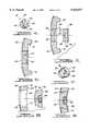
- FIG. 1is a perspective view of an assembled acetabular prosthesis according to the teachings of the preferred embodiment of the present invention
- FIG. 2is an exploded perspective view of the acetabular prosthesis of FIG. 1;
- FIG. 3is a side cross-sectional view taken along line 3--3 of FIG. 1;
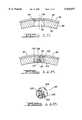
- FIG. 4is a perspective view of a threaded apical plug according to the teachings of the preferred embodiment of the present invention.
- FIG. 5is a side cross-sectional view of the threaded apical plug and threaded apical hole
- FIG. 6is a side cross-sectional view of the threaded apical plug threaded into the threaded apical hole
- FIG. 7is a perspective view of a dome plug according to the teachings of the preferred embodiment of the present invention.
- FIG. 8is a side cross-sectional view of the dome plug and dome plug hole
- FIG. 9is a side cross-sectional view of the dome plug engaged in the dome plug hole.
- FIG. 10is a side cross-sectional view of a plug according to the teachings of a second preferred embodiment of the present invention.
- FIG. 11Ais a side cross-sectional view of a plug according to the teachings of a third preferred embodiment of the present invention.
- FIG. 11Bis a perspective view of the plug shown in FIG. 11A;
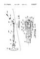
- FIG. 12is an exploded perspective view of a removal instrument utilized to remove the dome plug shown in FIG. 7;
- FIG. 13is an assembled side cross-sectional view of one end of the removed instrument shown in FIG. 12;
- FIGS. 14A-14Iillustrate a method for implanting the acetabular prosthesis according to the teachings of the preferred embodiment of the present invention.
- the acetabular prosthesis 10includes a full-hemisphere acetabular shell component 12, a congruent shell liner 14, an apical plug 16, and a plurality of pre-installed dome plugs 18.
- the acetabular shell component 12includes a smooth inner concave surface 20 and a roughened or porous coated outer convex or medial surface 22.
- the acetabular shell component 12is made from suitable biocompatible material such as titanium, stainless steel, titanium alloys, cobalt-chrome-molybdenum alloy and is preferably made of the titanium alloy TI-6AL-4V.
- the acetabular shell component 12further includes an annular face 24 having a shoulder 26.
- the shell liner 14is preferably formed from polyethylene or other suitable liner material.
- the shell liner 14includes an outer convex surface 30 and an inner concave surface 32.
- the outer convex surface 30is fully congruent and mates with the inner concave surface 20 of the shell component 12 to minimize relative motion between the components.
- the inner concave surface 32creates a uniform thickness of the shell liner 14 and acts as a bearing surface for a head of a hip prosthesis so as to dissipate stresses over the entire shell liner 14.
- the shell liner 14is secured to the acetabular shell component 12 by means of a locking ring 40 that engages grooves 42 and 44 formed, respectively, into the shell component 12 and the shell liner 14.
- the locking ring 40substantially reduces or eliminates micro-motion between the shell component 12 and the shell liner 14.
- the threaded center or apical plug 16which is preferably formed from the same titanium alloy as the acetabular shell component 12, is shown in operative association with a selectively pluggable threaded center or apical hole 46.
- the threaded apical hole 46is defined by a cylindrical threaded sidewall 48 and a beveled shelf 50.
- the threaded apical hole 46is used to receive various instruments, such as a threaded inserter, for use in implantation of the acetabular shell component 12, as well as for receiving the threaded apical plug 16.
- the threaded apical plug 16includes a conical or tapered threaded sidewall 52 having a chamfered end 54, a V-shaped groove 56 and a beveled seat 58.
- the tapered threaded sidewall 52tapers at an angle 59 of about 4° to create an interference fit within the acetabular shell component 12 upon threading the apical plug 16 into the cylindrical threaded apical hole 46.
- the tapered threaded sidewall 52threadably engages the cylindrical threaded sidewall 48, while the beveled seat 58 substantially seats against the beveled shelf 50, shown clearly in FIG. 6.
- the interference fit of the tapered threaded sidewall 52 with the cylindrical threaded sidewall 48, along with the beveled seat 58 engaging and mating with the beveled shelf 50provides for a substantially fluid tight seal, thereby minimizing the migration of wear debris out of the shell component 12.
- the apical plug 16further includes a planar exterior surface 60 and a spherical internal surface 62 having a hexagonal bore 64.
- the hexagonal bore 64is engaged by a hex driver to install the apical plug 16 into the threaded apical hole 46.
- the spherical internal surface 62accommodates for the shell liner 14.
- the dome plug 18which is also preferably formed from the same titanium alloy as the acetabular shell component 12, is shown in operative association with a selectively pluggable dome hole 66.
- the dome hole 66is defined by a cylindrical sidewall 68 and a spherical sidewall 70.
- the dome plug 18includes a cylindrical sidewall 72, an arcuate groove 74 and a congruent spherical sidewall 76.
- the diameter of the cylindrical sidewall 72 of the dome plug 18is larger than the diameter of the cylindrical sidewall 68 of the acetabular shell component 12 such that the dome plug 18 is press fit and matingly received into the dome hole 66 to substantially seal the dome hole 66 with the dome plug 18.
- the cylindrical sidewall 68 of the dome hole 66preferably has a diameter of about 0.2710 inches and the cylindrical sidewall 72 of the dome plug 18 preferably has a diameter of about 0.2719 inches.
- the arcuate groove 74allows the dome plug 18 to sit deeper within the dome hole 66 by providing relief in the dome plug 18 and eliminating a corner to allow full seating.
- the spherical sidewall 76 of the dome plug 18also mates with the spherical sidewall 70 of the dome hole 66.
- the dome plug 18further includes a spherical roughened or porous coated exterior surface 78 and a smooth spherical interior surface 80 having a threaded bore 82.
- the threaded bore 82provides means for threadably receiving an instrument for removal of the dome plug 18.
- the exterior surface 78is substantially flush with the porous coated surface 22 and the interior surface 80 seats slightly beneath or substantially flush with the inner concave surface 20.
- the dome plugs 18are positioned at a superior quadrant 84 of the acetabular shell component 12. Specifically, five pre-plugged dome holes 66 are in the superior quadrant 84 which receive five (5) press fit dome plugs 18.
- the dome plugs 18are pre-installed into the acetabular shell component 12 by press fitting to provide a substantially fluid tight seal that will reduce the migration of debris to the medial convex side 22 of the shell component 12. If screw fixation is required, the desired dome plug 18 can be removed either before or after the acetabular shell component 12 is implanted into an acetabulum.
- FIG. 10a side cross-sectional view of a disk-shaped plug 86 according to the teachings of a second preferred embodiment of the present invention is shown.
- the plug 86is preferably constructed from polymethylmethacrylate (PMMA) or other suitable biocompatible material and may be installed and fitted with various acetabular shell components 88 having holes 90.
- the plug 86may be retrofitted to conventional acetabular shell components 88, custom acetabular shell components or revision-type acetabular shell components that do not have holes designed to receive specific shaped plugs, such as the apical plug 16 or the dome plugs 18.
- a ledge 94is generally formed around the periphery of the hole 90.
- the plug 86is secured to the ledge 94 by means of ultra-sonic energy, heat energy, mechanical or chemical bonding, or other appropriate fixation means.
- non-mechanical fixationi.e., chemical, etc.
- a complete sealis achieved, which is sometimes very difficult to achieve with mechanical fixation.
- the plug 86may simply be removed by pushing through the hole 90 with an instrument, thereby knocking the plug 86 off the ledge 94, prior to implanting the acetabular shell component 88.
- the plug 86may simply be drilled through prior to implantation of the acetabular shell component 88. Since the plug 86 is affixed to the outer convex surface 96 of the acetabular shell component 88, the plug 86 may be affixed to various acetabular shell components either before or during surgery should it be desirable to seal specific holes 90, thereby minimizing or restricting the flow of debris out through the medial convex side 96 of the acetabular shell component 88. Moreover, the plug 86 may also be used to keep cement out of the interior 97 of the acetabular shell component 88 should the acetabular shell component 88 be cemented in place.
- the surgeonwill have the option to use only screw fixation or cement fixation of the acetabular shell component 88, or a combination of both, providing further versatility.
- the plug 86may either be drilled through after press-fitting the acetabular shell component 88 or a self tapping fixation screw can simply be driven through the plug 86, providing a further seal around the fixation screw.
- the plug 86may be drilled through after cementing or a self-tapping fixation screw can simply be driven through the plug 86. This inhibits cement from entering the interior 97 of the acetabular shell component 88 and eliminates cement under the screw head.
- PMMAis generally a transparent material and the plug 86 therefore acts as a "window" for the surgeon. This enables the surgeon to determine if proper seating of the acetabular shell component 88 is made, without having to have exposed holes 90.
- any other suitable transparent biocompatible materialmay also be used to provide similar results.
- the plug 98is preferably constructed of the same titanium alloy as the acetabular shell component 12 and is made to snap into the hole 90 of the acetabular shell component 88.
- the plug 98includes a tapered sidewall 100, a channel 102 and a spherical sidewall 104.
- the plug 98further includes grooves 106 formed into the plug 98 which enables the plug 98 to flex as the plug 98 is snapped into the hole 90.
- a threaded bore 107is also formed into the plug 98 to allow for removal of the plug 98, similar to the dome plugs 18.
- the plug 98may be snapped into selected holes 90 either before or after implantation of the acetabular shell component 88.
- the plug 98seals off the hole 90 in the acetabular shell component 88 to reduce or prevent wear debris from the acetabular shell component 88 and the shell liner 14 from passing through to the medial convex side 96 of acetabular shell component 88.
- the removal instrument 108includes a ratchet handle 110, an O-ring 111, a rigid shaft 112 having a universal joint 114 and an internally threaded socket 116, a socket bearing or bushing 118 and a threaded plug puller knob 120.
- the ratchet handle 110includes an internal ratchet mechanism and a bore 122 operable to receive a first end 124 of the rigid shaft 112 along with the O-ring 111.
- At the opposite end of the shaft 112is the universal or swivel joint 114 and the socket 116.
- the socket 116includes an external groove 126 and an internally threaded bore 128.
- the socket bushing 118is preferably comprised of polyethylene and includes resilient fingers 130 which engage and resiliently snap into groove 126 such that an inner sidewall 132 of the bushing 118 mates with an outer sidewall 134 of the socket 116.
- the socket bushing 118further includes a bore 126, an abutting face 138 and an outer cylindrical sidewall 139.
- the bore 126is operable to pass the plug puller knob 120.
- the abutting face 138 and the outer cylindrical sidewall 139provides a means for preventing the inner concave surface 20 from being scratched or scarred by the removal instrument 108 during removal of a dome plug 18.
- the abutting face 138may be convex to better mate with the inner concave surface 20.
- the abutting face 138further acts as a bushing face to reduce friction as the bushing 118 engages the inner concave surface 20.
- the plug puller knob 120includes a threaded finger 140, a tapered sidewall 142, a cylindrical threaded sidewall 144, and a cylindrical neck portion 146 having a tapered region 148.
- the neck 146further includes a hexagonal bore 150 operable to receive a hex driver.
- the threaded finger 140threadably engages the threaded bore 82 of the dome plug 18.
- the threaded sidewall 144is threadably received by the internal threaded sidewall 128 of socket 116.
- the removal instrument 108is assembled by connecting the ratchet handle 110 to the shaft 112, via the bore 122.
- the socket bushing 118is snapped around the outer cylindrical sidewall 134 of the socket 116, as the fingers 130 engage the groove 126.
- the socket bushing 118prevents the removal instrument 108 from scratching or scarring the inner concave surface 20 of the acetabular shell component 12 upon removal of the selected dome plug 18.
- the plug puller knob 120is threadably received within the socket 116, via the internal threaded sidewall 128 and the threaded sidewall 144.
- a suitably sized acetabular prosthesis 10is selected which may involve the use of a suitably sized template, as is well known in the art.
- a suitably sized hip prosthesisis chosen to fit within the intramedullary canal of a host femur.
- the hip prosthesismay include many different types of hip prosthesis such as the Bi-Metric System, Mallory/Head System or Integral System, each available from Biomet Inc.
- the femuris dislocated to expose the acetabulum 154.
- the hip prosthesisis then implanted in a manner well known in the art.
- the acetabulum 154is reamed with a reamer 156 driven by a driver 158.
- the acetabulum 154is generally hemispherically reamed until concentric removal of all acetabular cartilage is achieved.
- acetabular trial gaugeswhich are well known in the art, may be used to determine or confirm the diameter of the acetabular shell component 12 to be used. With the proper sized acetabular shell component 12 selected, an impacting or inserting instrument 160 is threaded into the threaded hole 46 of the acetabular shell component 12.
- the inserting instrument 160comes to rest at a rectangular depression 161 in the shell component 12 and is used to properly position the acetabular shell component 12 by use of guide rods 162. It should further be noted that placement of fixation screws is generally in the superior posterior quadrant 84 should screw fixation be required.
- the inserter 160is solidly impacted to fully seat the acetabular shell component 12, such that firm rim fixation is achieved. Once the acetabular shell component 12 has been solidly impacted and affixed, the inserter 160 is then carefully removed from the threaded hole 46, thereby threadably disengaging the inserter 160 from the acetabular shell component 12.
- the apical hole 46is sealed with the apical plug 16.
- the hexagonal bore 64 of the apical plug 16is engaged by a 2.5 millimeter hex screwdriver 164 that is used to tighten the apical plug 16 into the acetabular shell component 12.
- the tapered threaded sidewall 52threadably engages the cylindrical threaded sidewall 48 and the beveled seat 58 engages the beveled shelf 50, thereby providing a substantially fluid tight seal between the inner concave surface 20 and the medial outer convex surface 22.
- dome plugs 18can be removed using the removal instrument 108.
- the five dome plugs 18are positioned in a clustered arrangement in the superior posterior quadrant 84 in one embodiment to allow for fixation in several areas within this quadrant 84. However, the dome plugs 18 may be positioned in any location about the acetabular shell component 12.
- the socket 116Upon turning the removal tool 108 in a clockwise turning motion, the socket 116 having internal threaded sidewall 128, threadably receives the plug puller knob 120, via the threaded sidewall 144.
- the abutting face 138 of the bushing 118, as well as the outer sidewall 139 of the bushing 118prevents the smooth inner concave surface 20 from being scratched or scarred during removal of the selected dome plug 18.
- the abutting face 138engages the inner concave surface 20.
- the removal instrument 108is then further rotated clockwise, via the ratchet handle 110. This additional turning draws the plug puller knob 120 further up into the threaded socket 116 to break the press fit seal and easily remove the selected dome plug 18.
- the selected dome plug 18may either be removed before or after the acetabular shell component 12 has been implanted into the acetabulum 154. Removal of the dome plug 18 after implantation of the shell component 12 is achieved since the removal instrument 108 does not create an axial or transverse pulling force on the shell component 12. In other words, the shell component 12 is held firmly in place as it is being engaged by the bushing 118, and the dome plug 18 seal is broken by both rotational and axially forces being applied to the dome plug 18 during the drawing up of the plug puller knob 120 into the socket 116.
- the bushing 118 and the plug puller knob 120may be disposed of.
- the fixation screw holes 170are then drilled into the acetabulum 154 using a flexible drill shaft 172 and a drill bit 174.
- An optional drill guideas known in the art, may be used to position the drill bit 174 relative to the hole 66.
- a depth gaugeas is also known in the art, may be used to determine the length of the screw. With the length of the screw determined, a fixation screw 176 is inserted into the screw hole 170 using a universal screw driver 178. With the fixation screws 176 firmly secured and seated in the dome holes 66, the acetabular shell component 12 may be thoroughly cleaned and a trial liner, as known in the art, may be inserted into the acetabular shell component 12.
- a trial reductioncan be carried out to check the full range of motion including extension, external rotation, flexion, and abduction.
- the shell liner 14is firmly seated within the acetabular shell component 12.
- the shell liner 14is appropriately seated by firmly impacting the shell liner 14 against the acetabular shell component 12.
- the ring-lock 40engages the grooves 42 and 44, thereby preventing movement of the shell liner 14 relative to the acetabular shell component 12.
- a head 180 of a hip prosthesis 182which is implanted into a femur 184 is then installed in a manner known in the art into the acetabular prosthesis 10 with the head 180 bearing on the shell liner 14.
- both the apical plug 16 and the dome plugs 18substantially reduces or eliminates any wear debris occurring within the inner concave surface 12 from migrating through the acetabular shell component 12 to the outer convex surface 22.
- use of the apical plug 16 and the dome plugs 18further enables a cement mantle to be formed along the outer convex surface 22, should it be desired, without having cement enter the inner concave surface 20.
- pre-installed dome plugs 18which may be removed either before or after implantation of the acetabular shell component 12, surgical time is reduced, as well as surgical flexibility increased, thereby lowering overall surgical cost.
Landscapes
- Health & Medical Sciences (AREA)
- Orthopedic Medicine & Surgery (AREA)
- Life Sciences & Earth Sciences (AREA)
- Transplantation (AREA)
- Oral & Maxillofacial Surgery (AREA)
- General Health & Medical Sciences (AREA)
- Engineering & Computer Science (AREA)
- Biomedical Technology (AREA)
- Heart & Thoracic Surgery (AREA)
- Veterinary Medicine (AREA)
- Public Health (AREA)
- Animal Behavior & Ethology (AREA)
- Vascular Medicine (AREA)
- Cardiology (AREA)
- Physical Education & Sports Medicine (AREA)
- Surgery (AREA)
- Dentistry (AREA)
- Nuclear Medicine, Radiotherapy & Molecular Imaging (AREA)
- Medical Informatics (AREA)
- Molecular Biology (AREA)
- Prostheses (AREA)
Abstract
Description
Claims (11)
Priority Applications (1)
| Application Number | Priority Date | Filing Date | Title |
|---|---|---|---|
| US08/832,477US5925077A (en) | 1997-04-02 | 1997-04-02 | Apparatus and method for plugging holes in an acetabular shell component |
Applications Claiming Priority (1)
| Application Number | Priority Date | Filing Date | Title |
|---|---|---|---|
| US08/832,477US5925077A (en) | 1997-04-02 | 1997-04-02 | Apparatus and method for plugging holes in an acetabular shell component |
Publications (1)
| Publication Number | Publication Date |
|---|---|
| US5925077Atrue US5925077A (en) | 1999-07-20 |
Family
ID=25261765
Family Applications (1)
| Application Number | Title | Priority Date | Filing Date |
|---|---|---|---|
| US08/832,477Expired - LifetimeUS5925077A (en) | 1997-04-02 | 1997-04-02 | Apparatus and method for plugging holes in an acetabular shell component |
Country Status (1)
| Country | Link |
|---|---|
| US (1) | US5925077A (en) |
Cited By (56)
| Publication number | Priority date | Publication date | Assignee | Title |
|---|---|---|---|---|
| FR2826865A1 (en)* | 2001-07-06 | 2003-01-10 | Fournitures Hospitalieres Ind | Cotyloid implant for hip prosthesis has holes for fixing screws covered by detachable plugs |
| US20030149433A1 (en)* | 2000-06-09 | 2003-08-07 | Markus Hehli | Plastic implant for osteosynthesis |
| EP1338256A1 (en)* | 2002-02-26 | 2003-08-27 | DePuy Products, Inc. | Acetabular component with removable screw hole plugs |
| FR2838329A1 (en)* | 2002-04-15 | 2003-10-17 | Taloco Invest N V | Cotyle structure for treating hip complaints has one or more fixing holes with temporary plugs that can be broken off prior to use |
| WO2003094739A3 (en)* | 2002-05-07 | 2004-02-19 | Depuy Int Ltd | An assembly for use in orthopaedic surgery |
| US6709462B2 (en) | 2002-01-11 | 2004-03-23 | Mayo Foundation For Medical Education And Research | Acetabular shell with screw access channels |
| US20040111162A1 (en)* | 2002-12-05 | 2004-06-10 | Southworth Carleton B. | Apparatus and method for advancing synovial fluid in a prosthetic joint |
| EP1442729A1 (en)* | 2003-01-31 | 2004-08-04 | Howmedica Osteonics Corp. | Adjustable reamer with tip tracker linkage |
| US20050216022A1 (en)* | 2002-04-30 | 2005-09-29 | Precimed S.A. | Reamer spindle for minimally invasive joint surgery |
| US20060095043A1 (en)* | 2004-10-19 | 2006-05-04 | Martz Erik O | Adjustable instrumentation for spinal implant insertion |
| EP1728489A1 (en)* | 2005-06-03 | 2006-12-06 | Mathys AG Bettlach | Hip endoprosthesis with acetabular having sealed bores |
| US20070129809A1 (en)* | 2005-12-05 | 2007-06-07 | Biomet Manufacturing Corp. | Apparatus for use of porous implants |
| US20070250175A1 (en)* | 2001-02-23 | 2007-10-25 | Biomet Manufacturing Corp. | Method And Appartus For Acetabular Reconstruction |
| US7335207B1 (en)* | 2003-11-26 | 2008-02-26 | Biomet Manufacturing Corp. | Minimally invasive cup impactor |
| US7338496B1 (en)* | 2003-08-29 | 2008-03-04 | Biomet Manufacturing Corp. | Method and apparatus for positioning an implant |
| US7597715B2 (en)* | 2005-04-21 | 2009-10-06 | Biomet Manufacturing Corp. | Method and apparatus for use of porous implants |
| US7635447B2 (en) | 2006-02-17 | 2009-12-22 | Biomet Manufacturing Corp. | Method and apparatus for forming porous metal implants |
| US7655009B2 (en)* | 2003-12-01 | 2010-02-02 | Smith & Nephew, Inc. | Humeral nail |
| EP2158876A1 (en)* | 2008-09-02 | 2010-03-03 | Zimmer GmbH | Plug for covering screw holes in prostethic implants |
| US8066778B2 (en) | 2005-04-21 | 2011-11-29 | Biomet Manufacturing Corp. | Porous metal cup with cobalt bearing surface |
| US8266780B2 (en) | 2005-04-21 | 2012-09-18 | Biomet Manufacturing Corp. | Method and apparatus for use of porous implants |
| US8292967B2 (en) | 2005-04-21 | 2012-10-23 | Biomet Manufacturing Corp. | Method and apparatus for use of porous implants |
| US20130053898A1 (en)* | 2011-08-25 | 2013-02-28 | Synthes Usa, Llc | Implant |
| US8535384B2 (en) | 2011-08-10 | 2013-09-17 | Biomet Manufacturing, Llc | Acetabular screw hole covers with porous coating |
| US8568487B2 (en) | 2006-02-27 | 2013-10-29 | Biomet Manufacturing, Llc | Patient-specific hip joint devices |
| US8597365B2 (en) | 2011-08-04 | 2013-12-03 | Biomet Manufacturing, Llc | Patient-specific pelvic implants for acetabular reconstruction |
| US8603180B2 (en) | 2006-02-27 | 2013-12-10 | Biomet Manufacturing, Llc | Patient-specific acetabular alignment guides |
| US8608749B2 (en) | 2006-02-27 | 2013-12-17 | Biomet Manufacturing, Llc | Patient-specific acetabular guides and associated instruments |
| US20140277547A1 (en)* | 2013-03-15 | 2014-09-18 | DePuy Synthes Products, LLC | Mechanical assembly of pegs to prosthesis |
| US9113971B2 (en) | 2006-02-27 | 2015-08-25 | Biomet Manufacturing, Llc | Femoral acetabular impingement guide |
| USD744097S1 (en)* | 2014-12-15 | 2015-11-24 | Integra Lifesciences Corporation | Orthopedic implant sizer |
| US9339278B2 (en) | 2006-02-27 | 2016-05-17 | Biomet Manufacturing, Llc | Patient-specific acetabular guides and associated instruments |
| US9386993B2 (en) | 2011-09-29 | 2016-07-12 | Biomet Manufacturing, Llc | Patient-specific femoroacetabular impingement instruments and methods |
| US9398956B2 (en) | 2007-09-25 | 2016-07-26 | Depuy (Ireland) | Fixed-bearing knee prosthesis having interchangeable components |
| US9700329B2 (en) | 2006-02-27 | 2017-07-11 | Biomet Manufacturing, Llc | Patient-specific orthopedic instruments |
| US9743935B2 (en) | 2011-03-07 | 2017-08-29 | Biomet Manufacturing, Llc | Patient-specific femoral version guide |
| US9795399B2 (en) | 2006-06-09 | 2017-10-24 | Biomet Manufacturing, Llc | Patient-specific knee alignment guide and associated method |
| US9808665B1 (en)* | 2016-06-25 | 2017-11-07 | Eternal Evolution LLC | Exercise device |
| CN107613909A (en)* | 2015-06-07 | 2018-01-19 | 联合创新技术有限责任公司 | Mohs cone protects sleeve |
| US9968376B2 (en) | 2010-11-29 | 2018-05-15 | Biomet Manufacturing, Llc | Patient-specific orthopedic instruments |
| US9993337B1 (en)* | 2007-07-19 | 2018-06-12 | Osteosymbionics, Llc | Orthopaedic implant and method of making same |
| WO2018111651A1 (en) | 2016-12-12 | 2018-06-21 | Zimmer, Inc. | Implants with frangible fastener port plugs |
| US10098648B2 (en) | 2010-09-29 | 2018-10-16 | Biomet Manufacturing, Llc | Patient-specific guide for partial acetabular socket replacement |
| US10159498B2 (en) | 2008-04-16 | 2018-12-25 | Biomet Manufacturing, Llc | Method and apparatus for manufacturing an implant |
| US10278711B2 (en) | 2006-02-27 | 2019-05-07 | Biomet Manufacturing, Llc | Patient-specific femoral guide |
| US10307255B1 (en) | 2017-11-29 | 2019-06-04 | b-ONE Ortho, Corp. | Acetabular cup assembly |
| US10390845B2 (en) | 2006-02-27 | 2019-08-27 | Biomet Manufacturing, Llc | Patient-specific shoulder guide |
| US10426492B2 (en) | 2006-02-27 | 2019-10-01 | Biomet Manufacturing, Llc | Patient specific alignment guide with cutting surface and laser indicator |
| US10603179B2 (en) | 2006-02-27 | 2020-03-31 | Biomet Manufacturing, Llc | Patient-specific augments |
| US10722310B2 (en) | 2017-03-13 | 2020-07-28 | Zimmer Biomet CMF and Thoracic, LLC | Virtual surgery planning system and method |
| US10743937B2 (en) | 2006-02-27 | 2020-08-18 | Biomet Manufacturing, Llc | Backup surgical instrument system and method |
| US20200289292A1 (en)* | 2019-03-12 | 2020-09-17 | Howmedica Osteonics Corp. | Anatomic Shell 2-in-1 Window Trial |
| US20200337940A1 (en)* | 2019-04-25 | 2020-10-29 | Samantha G. HUNTER | Baby roller burpee and soothing massaging device |
| US11534313B2 (en) | 2006-02-27 | 2022-12-27 | Biomet Manufacturing, Llc | Patient-specific pre-operative planning |
| US11554019B2 (en) | 2007-04-17 | 2023-01-17 | Biomet Manufacturing, Llc | Method and apparatus for manufacturing an implant |
| US12127991B2 (en)* | 2018-05-04 | 2024-10-29 | Zackary Daley | Exercise device having telescoping elements |
Citations (40)
| Publication number | Priority date | Publication date | Assignee | Title |
|---|---|---|---|---|
| US3840904A (en)* | 1973-04-30 | 1974-10-15 | R Tronzo | Acetabular cup prosthesis |
| US3866248A (en)* | 1974-04-08 | 1975-02-18 | Abcor Inc | Cement restrictor for total hip operations |
| US3906550A (en)* | 1973-12-27 | 1975-09-23 | William Rostoker | Prosthetic device having a porous fiber metal structure |
| US4001928A (en)* | 1973-01-04 | 1977-01-11 | Raychem Corporation | Method for plugging an aperture with a heat recoverable plug |
| US4285071A (en)* | 1979-07-02 | 1981-08-25 | Nelson Carl L | Method of securing a prosthesis using cement spacers |
| US4417571A (en)* | 1979-07-02 | 1983-11-29 | Nelson Carl L | Prosthetic cement spacer and method for using same |
| US4563778A (en)* | 1983-02-23 | 1986-01-14 | Minnesota Mining And Manufacturing Company | Prosthetic acetabular cup |
| US4566138A (en)* | 1983-03-08 | 1986-01-28 | Zimmer, Inc. | Prosthetic device with spacers |
| US4659331A (en)* | 1983-11-28 | 1987-04-21 | Regents Of University Of Michigan | Prosthesis interface surface and method of implanting |
| US4666450A (en)* | 1983-08-26 | 1987-05-19 | Pfizer Hospital Products Group, Inc. | Acetabular cup assembly prosthesis |
| US4711234A (en)* | 1986-02-11 | 1987-12-08 | Societe Europeen De Propulsion | Bio-compatible retention pin, and a prosthesis including such a pin |
| US4778473A (en)* | 1983-11-28 | 1988-10-18 | The University Of Michigan | Prosthesis interface surface and method of implanting |
| US4883491A (en)* | 1986-01-21 | 1989-11-28 | Joint Medical Products Corporation | Porous-coated artificial joints |
| EP0346270A1 (en)* | 1988-06-06 | 1989-12-13 | Mecron Medizinische Produkte Gmbh | Screw-in cup for a hip joint prosthesis |
| US4919666A (en)* | 1986-05-05 | 1990-04-24 | Sulzer Brothers Limited | Implant having recesses for therapeutically effective substances |
| US4923473A (en)* | 1988-03-01 | 1990-05-08 | Sulzer Brothers Limited | Hemispherical acetabulum |
| FR2638963A1 (en)* | 1988-11-14 | 1990-05-18 | Tornier Sa | Artificial acetabula with studs for a total hip prosthesis |
| US4936856A (en)* | 1987-11-03 | 1990-06-26 | Waldemar Link Gmbh & Co. | Hip joint socket prosthesis |
| US4955325A (en)* | 1989-06-14 | 1990-09-11 | Osteonics Corp. | Acetabular cup component cement spacer system |
| US4955917A (en)* | 1988-04-11 | 1990-09-11 | Sulzer Brothers Limited | Prosthetic acetabulum |
| US5009665A (en)* | 1989-02-08 | 1991-04-23 | Boehringer Mannheim Corp. | Acetabular cup |
| US5021062A (en)* | 1989-06-21 | 1991-06-04 | Jose Adrey | Acetabular cup assembly |
| US5032134A (en)* | 1983-12-16 | 1991-07-16 | Jonas Lindwer | Joint prosthesis and tool to be used therewith |
| US5041141A (en)* | 1987-11-03 | 1991-08-20 | Orthopaedic Technology B.V. | Method of shaping an endo-prosthesis, a femoral head prosthesis, an acetabulum prosthesis and a method of fixing a femoral head prosthesis in a bone |
| US5156625A (en)* | 1989-09-28 | 1992-10-20 | Sulzer Brothers Limited | Acetabular prosthesis having a metal supporting shell |
| US5197989A (en)* | 1987-09-03 | 1993-03-30 | Hinckfuss Bruce W | Two stage joint prosthesis |
| US5211665A (en)* | 1992-03-04 | 1993-05-18 | Ku Ming C | Acetabular cup assembly for total hip replacement |
| US5217499A (en)* | 1988-08-17 | 1993-06-08 | Minnesota Mining And Manufacturing Company | Rim-bearing acetabular component of hip joint prosthesis |
| FR2685192A1 (en)* | 1991-12-24 | 1993-06-25 | Osteal Medical Laboratoires | Metal acetabulum for coxofemoral joint prosthesis |
| US5226917A (en)* | 1991-02-14 | 1993-07-13 | Smith & Nephew Richards Inc. | Acetabular prosthesis with anchoring pegs |
| US5282864A (en)* | 1992-02-19 | 1994-02-01 | Joint Medical Products Corporation | Acetabular prosthesis having a metal socket bearing |
| US5310408A (en)* | 1991-02-14 | 1994-05-10 | Smith & Nephew Richards Inc. | Acetabular cup body prosthesis |
| US5314494A (en)* | 1987-11-03 | 1994-05-24 | Orthopaedic Technology B.V. | Endo-prosthesis, a femoral head prosthesis and an acetabulum prosthesis |
| US5360452A (en)* | 1991-05-20 | 1994-11-01 | Depuy Inc. | Enhanced fixation system for a prosthetic implant |
| US5370702A (en)* | 1993-06-17 | 1994-12-06 | Stelkast Incorporated | Acetabular cup having optionally removable portions |
| WO1995030389A1 (en)* | 1994-05-09 | 1995-11-16 | Smith & Nephew Richards Inc. | Orthopedic prosthesis |
| WO1996003096A1 (en)* | 1994-07-25 | 1996-02-08 | Joint Medical Products Corporation | Acetabular prosthesis |
| WO1996023457A1 (en)* | 1995-01-31 | 1996-08-08 | Howmedica Inc. | Acetabular plug |
| US5571198A (en)* | 1994-01-21 | 1996-11-05 | David A. Drucker | Acetabular shell with selectively available bone screw holds |
| US5725580A (en)* | 1994-12-16 | 1998-03-10 | Exactech, Inc. | Hole caps for prosthetic implants |
- 1997
- 1997-04-02USUS08/832,477patent/US5925077A/ennot_activeExpired - Lifetime
Patent Citations (44)
| Publication number | Priority date | Publication date | Assignee | Title |
|---|---|---|---|---|
| US4001928A (en)* | 1973-01-04 | 1977-01-11 | Raychem Corporation | Method for plugging an aperture with a heat recoverable plug |
| US3840904A (en)* | 1973-04-30 | 1974-10-15 | R Tronzo | Acetabular cup prosthesis |
| US3906550A (en)* | 1973-12-27 | 1975-09-23 | William Rostoker | Prosthetic device having a porous fiber metal structure |
| US3866248A (en)* | 1974-04-08 | 1975-02-18 | Abcor Inc | Cement restrictor for total hip operations |
| US4285071A (en)* | 1979-07-02 | 1981-08-25 | Nelson Carl L | Method of securing a prosthesis using cement spacers |
| US4417571A (en)* | 1979-07-02 | 1983-11-29 | Nelson Carl L | Prosthetic cement spacer and method for using same |
| US4563778A (en)* | 1983-02-23 | 1986-01-14 | Minnesota Mining And Manufacturing Company | Prosthetic acetabular cup |
| US4566138A (en)* | 1983-03-08 | 1986-01-28 | Zimmer, Inc. | Prosthetic device with spacers |
| US4666450A (en)* | 1983-08-26 | 1987-05-19 | Pfizer Hospital Products Group, Inc. | Acetabular cup assembly prosthesis |
| US4659331A (en)* | 1983-11-28 | 1987-04-21 | Regents Of University Of Michigan | Prosthesis interface surface and method of implanting |
| US4778473A (en)* | 1983-11-28 | 1988-10-18 | The University Of Michigan | Prosthesis interface surface and method of implanting |
| US5032134A (en)* | 1983-12-16 | 1991-07-16 | Jonas Lindwer | Joint prosthesis and tool to be used therewith |
| US4883491A (en)* | 1986-01-21 | 1989-11-28 | Joint Medical Products Corporation | Porous-coated artificial joints |
| US4944759A (en)* | 1986-01-21 | 1990-07-31 | Joint Medical Products Corporation | Porous-coated artificial joints |
| US4711234A (en)* | 1986-02-11 | 1987-12-08 | Societe Europeen De Propulsion | Bio-compatible retention pin, and a prosthesis including such a pin |
| US4919666A (en)* | 1986-05-05 | 1990-04-24 | Sulzer Brothers Limited | Implant having recesses for therapeutically effective substances |
| US5197989A (en)* | 1987-09-03 | 1993-03-30 | Hinckfuss Bruce W | Two stage joint prosthesis |
| US5041141A (en)* | 1987-11-03 | 1991-08-20 | Orthopaedic Technology B.V. | Method of shaping an endo-prosthesis, a femoral head prosthesis, an acetabulum prosthesis and a method of fixing a femoral head prosthesis in a bone |
| US4936856A (en)* | 1987-11-03 | 1990-06-26 | Waldemar Link Gmbh & Co. | Hip joint socket prosthesis |
| US5314494A (en)* | 1987-11-03 | 1994-05-24 | Orthopaedic Technology B.V. | Endo-prosthesis, a femoral head prosthesis and an acetabulum prosthesis |
| US4923473A (en)* | 1988-03-01 | 1990-05-08 | Sulzer Brothers Limited | Hemispherical acetabulum |
| US4955917A (en)* | 1988-04-11 | 1990-09-11 | Sulzer Brothers Limited | Prosthetic acetabulum |
| EP0346270A1 (en)* | 1988-06-06 | 1989-12-13 | Mecron Medizinische Produkte Gmbh | Screw-in cup for a hip joint prosthesis |
| US5217499A (en)* | 1988-08-17 | 1993-06-08 | Minnesota Mining And Manufacturing Company | Rim-bearing acetabular component of hip joint prosthesis |
| FR2638963A1 (en)* | 1988-11-14 | 1990-05-18 | Tornier Sa | Artificial acetabula with studs for a total hip prosthesis |
| US5009665A (en)* | 1989-02-08 | 1991-04-23 | Boehringer Mannheim Corp. | Acetabular cup |
| US4955325A (en)* | 1989-06-14 | 1990-09-11 | Osteonics Corp. | Acetabular cup component cement spacer system |
| US5021062A (en)* | 1989-06-21 | 1991-06-04 | Jose Adrey | Acetabular cup assembly |
| US5156625A (en)* | 1989-09-28 | 1992-10-20 | Sulzer Brothers Limited | Acetabular prosthesis having a metal supporting shell |
| US5310408B1 (en)* | 1991-02-14 | 1997-02-11 | Smith & Nephew Richards Inc | Acetabular cup body prosthesis |
| US5226917A (en)* | 1991-02-14 | 1993-07-13 | Smith & Nephew Richards Inc. | Acetabular prosthesis with anchoring pegs |
| US5310408A (en)* | 1991-02-14 | 1994-05-10 | Smith & Nephew Richards Inc. | Acetabular cup body prosthesis |
| US5314487A (en)* | 1991-02-14 | 1994-05-24 | Smith & Nephew Richards Inc. | Acetabular prosthesis with anchoring pegs |
| US5360452A (en)* | 1991-05-20 | 1994-11-01 | Depuy Inc. | Enhanced fixation system for a prosthetic implant |
| FR2685192A1 (en)* | 1991-12-24 | 1993-06-25 | Osteal Medical Laboratoires | Metal acetabulum for coxofemoral joint prosthesis |
| US5282864A (en)* | 1992-02-19 | 1994-02-01 | Joint Medical Products Corporation | Acetabular prosthesis having a metal socket bearing |
| US5211665A (en)* | 1992-03-04 | 1993-05-18 | Ku Ming C | Acetabular cup assembly for total hip replacement |
| US5370702A (en)* | 1993-06-17 | 1994-12-06 | Stelkast Incorporated | Acetabular cup having optionally removable portions |
| US5571198A (en)* | 1994-01-21 | 1996-11-05 | David A. Drucker | Acetabular shell with selectively available bone screw holds |
| WO1995030389A1 (en)* | 1994-05-09 | 1995-11-16 | Smith & Nephew Richards Inc. | Orthopedic prosthesis |
| WO1996003096A1 (en)* | 1994-07-25 | 1996-02-08 | Joint Medical Products Corporation | Acetabular prosthesis |
| US5549694A (en)* | 1994-07-25 | 1996-08-27 | Joint Medical Products Corporation | Acetabular prosthesis with apertures sealed with deformable discs and method |
| US5725580A (en)* | 1994-12-16 | 1998-03-10 | Exactech, Inc. | Hole caps for prosthetic implants |
| WO1996023457A1 (en)* | 1995-01-31 | 1996-08-08 | Howmedica Inc. | Acetabular plug |
Non-Patent Citations (3)
| Title |
|---|
| Biomet, Inc., Vision Hip System Acetabular Series, copyright 1996 (19 pp.).* |
| Intermedics Orthopedics, Inc., Inter Op Acetabular System; Copyright 1997 (4 pp.).* |
| Intermedics Orthopedics, Inc., Inter-Op Acetabular System; Copyright 1997 (4 pp.). |
Cited By (97)
| Publication number | Priority date | Publication date | Assignee | Title |
|---|---|---|---|---|
| US20030149433A1 (en)* | 2000-06-09 | 2003-08-07 | Markus Hehli | Plastic implant for osteosynthesis |
| US20110071574A1 (en)* | 2000-06-09 | 2011-03-24 | Synthes Usa, Llc | Plastic Implant for Osteosynthesis |
| US7862596B2 (en)* | 2000-06-09 | 2011-01-04 | Synthes Usa, Llc | Plastic implant for osteosynthesis |
| US20070250175A1 (en)* | 2001-02-23 | 2007-10-25 | Biomet Manufacturing Corp. | Method And Appartus For Acetabular Reconstruction |
| US8123814B2 (en) | 2001-02-23 | 2012-02-28 | Biomet Manufacturing Corp. | Method and appartus for acetabular reconstruction |
| US9375316B2 (en) | 2001-02-23 | 2016-06-28 | Biomet Manufacturing, Llc. | Method and apparatus for acetabular reconstruction |
| US8551181B2 (en) | 2001-02-23 | 2013-10-08 | Biomet Manufacturing, Llc | Method and apparatus for acetabular reconstruction |
| FR2826865A1 (en)* | 2001-07-06 | 2003-01-10 | Fournitures Hospitalieres Ind | Cotyloid implant for hip prosthesis has holes for fixing screws covered by detachable plugs |
| US6709462B2 (en) | 2002-01-11 | 2004-03-23 | Mayo Foundation For Medical Education And Research | Acetabular shell with screw access channels |
| EP1338256A1 (en)* | 2002-02-26 | 2003-08-27 | DePuy Products, Inc. | Acetabular component with removable screw hole plugs |
| US20030163203A1 (en)* | 2002-02-26 | 2003-08-28 | Nycz Jeffrey H. | Acetabular component with removable screw hole plugs |
| FR2838329A1 (en)* | 2002-04-15 | 2003-10-17 | Taloco Invest N V | Cotyle structure for treating hip complaints has one or more fixing holes with temporary plugs that can be broken off prior to use |
| US20080065081A1 (en)* | 2002-04-30 | 2008-03-13 | Andre Lechot | Reamer spindle for minimally invasive joint surgery |
| US20050216022A1 (en)* | 2002-04-30 | 2005-09-29 | Precimed S.A. | Reamer spindle for minimally invasive joint surgery |
| US7780669B2 (en)* | 2002-04-30 | 2010-08-24 | Greatbatch Medical S.A. | Reamer spindle for minimally invasive joint surgery |
| US7637909B2 (en)* | 2002-04-30 | 2009-12-29 | Greatbatch Medical S.A. | Reamer spindle for minimally invasive joint surgery |
| US20090318922A9 (en)* | 2002-04-30 | 2009-12-24 | Precimed S.A. | Reamer spindle for minimally invasive joint surgery |
| WO2003094739A3 (en)* | 2002-05-07 | 2004-02-19 | Depuy Int Ltd | An assembly for use in orthopaedic surgery |
| US20050216020A1 (en)* | 2002-05-07 | 2005-09-29 | Marcus Orton | Assembly for use in orthopaedic surgery |
| US20040111162A1 (en)* | 2002-12-05 | 2004-06-10 | Southworth Carleton B. | Apparatus and method for advancing synovial fluid in a prosthetic joint |
| US7144427B2 (en) | 2002-12-05 | 2006-12-05 | Depuy Products, Inc. | Apparatus and method for advancing synovial fluid in a prosthetic joint |
| US7008430B2 (en) | 2003-01-31 | 2006-03-07 | Howmedica Osteonics Corp. | Adjustable reamer with tip tracker linkage |
| EP1442729A1 (en)* | 2003-01-31 | 2004-08-04 | Howmedica Osteonics Corp. | Adjustable reamer with tip tracker linkage |
| US20040153080A1 (en)* | 2003-01-31 | 2004-08-05 | Howmedica Osteonics Corp. | Adjustable reamer with tip tracker linkage |
| US8137358B2 (en) | 2003-08-29 | 2012-03-20 | Biomet Manufacturing Corp. | Method and apparatus for positioning an implant |
| US7338496B1 (en)* | 2003-08-29 | 2008-03-04 | Biomet Manufacturing Corp. | Method and apparatus for positioning an implant |
| US20080119861A1 (en)* | 2003-08-29 | 2008-05-22 | Biomet Manufacturing Corp. | Method And Apparatus For Positioning An Implant |
| US7335207B1 (en)* | 2003-11-26 | 2008-02-26 | Biomet Manufacturing Corp. | Minimally invasive cup impactor |
| US7655009B2 (en)* | 2003-12-01 | 2010-02-02 | Smith & Nephew, Inc. | Humeral nail |
| US20060095043A1 (en)* | 2004-10-19 | 2006-05-04 | Martz Erik O | Adjustable instrumentation for spinal implant insertion |
| US7988699B2 (en)* | 2004-10-19 | 2011-08-02 | Warsaw Orthopedic, Inc. | Adjustable instrumentation for spinal implant insertion |
| US7597715B2 (en)* | 2005-04-21 | 2009-10-06 | Biomet Manufacturing Corp. | Method and apparatus for use of porous implants |
| US8066778B2 (en) | 2005-04-21 | 2011-11-29 | Biomet Manufacturing Corp. | Porous metal cup with cobalt bearing surface |
| US8197550B2 (en) | 2005-04-21 | 2012-06-12 | Biomet Manufacturing Corp. | Method and apparatus for use of porous implants |
| US8266780B2 (en) | 2005-04-21 | 2012-09-18 | Biomet Manufacturing Corp. | Method and apparatus for use of porous implants |
| US8292967B2 (en) | 2005-04-21 | 2012-10-23 | Biomet Manufacturing Corp. | Method and apparatus for use of porous implants |
| EP1728489A1 (en)* | 2005-06-03 | 2006-12-06 | Mathys AG Bettlach | Hip endoprosthesis with acetabular having sealed bores |
| US8021432B2 (en) | 2005-12-05 | 2011-09-20 | Biomet Manufacturing Corp. | Apparatus for use of porous implants |
| US20070129809A1 (en)* | 2005-12-05 | 2007-06-07 | Biomet Manufacturing Corp. | Apparatus for use of porous implants |
| US7635447B2 (en) | 2006-02-17 | 2009-12-22 | Biomet Manufacturing Corp. | Method and apparatus for forming porous metal implants |
| US10390845B2 (en) | 2006-02-27 | 2019-08-27 | Biomet Manufacturing, Llc | Patient-specific shoulder guide |
| US9339278B2 (en) | 2006-02-27 | 2016-05-17 | Biomet Manufacturing, Llc | Patient-specific acetabular guides and associated instruments |
| US10206695B2 (en) | 2006-02-27 | 2019-02-19 | Biomet Manufacturing, Llc | Femoral acetabular impingement guide |
| US8568487B2 (en) | 2006-02-27 | 2013-10-29 | Biomet Manufacturing, Llc | Patient-specific hip joint devices |
| US9700329B2 (en) | 2006-02-27 | 2017-07-11 | Biomet Manufacturing, Llc | Patient-specific orthopedic instruments |
| US8603180B2 (en) | 2006-02-27 | 2013-12-10 | Biomet Manufacturing, Llc | Patient-specific acetabular alignment guides |
| US8608749B2 (en) | 2006-02-27 | 2013-12-17 | Biomet Manufacturing, Llc | Patient-specific acetabular guides and associated instruments |
| US11534313B2 (en) | 2006-02-27 | 2022-12-27 | Biomet Manufacturing, Llc | Patient-specific pre-operative planning |
| US9113971B2 (en) | 2006-02-27 | 2015-08-25 | Biomet Manufacturing, Llc | Femoral acetabular impingement guide |
| US9480580B2 (en) | 2006-02-27 | 2016-11-01 | Biomet Manufacturing, Llc | Patient-specific acetabular alignment guides |
| US10743937B2 (en) | 2006-02-27 | 2020-08-18 | Biomet Manufacturing, Llc | Backup surgical instrument system and method |
| US9913734B2 (en) | 2006-02-27 | 2018-03-13 | Biomet Manufacturing, Llc | Patient-specific acetabular alignment guides |
| US10603179B2 (en) | 2006-02-27 | 2020-03-31 | Biomet Manufacturing, Llc | Patient-specific augments |
| US10507029B2 (en) | 2006-02-27 | 2019-12-17 | Biomet Manufacturing, Llc | Patient-specific acetabular guides and associated instruments |
| US10426492B2 (en) | 2006-02-27 | 2019-10-01 | Biomet Manufacturing, Llc | Patient specific alignment guide with cutting surface and laser indicator |
| US10278711B2 (en) | 2006-02-27 | 2019-05-07 | Biomet Manufacturing, Llc | Patient-specific femoral guide |
| US10893879B2 (en) | 2006-06-09 | 2021-01-19 | Biomet Manufacturing, Llc | Patient-specific knee alignment guide and associated method |
| US10206697B2 (en) | 2006-06-09 | 2019-02-19 | Biomet Manufacturing, Llc | Patient-specific knee alignment guide and associated method |
| US9795399B2 (en) | 2006-06-09 | 2017-10-24 | Biomet Manufacturing, Llc | Patient-specific knee alignment guide and associated method |
| US11576689B2 (en) | 2006-06-09 | 2023-02-14 | Biomet Manufacturing, Llc | Patient-specific knee alignment guide and associated method |
| US11554019B2 (en) | 2007-04-17 | 2023-01-17 | Biomet Manufacturing, Llc | Method and apparatus for manufacturing an implant |
| US9993337B1 (en)* | 2007-07-19 | 2018-06-12 | Osteosymbionics, Llc | Orthopaedic implant and method of making same |
| US9398956B2 (en) | 2007-09-25 | 2016-07-26 | Depuy (Ireland) | Fixed-bearing knee prosthesis having interchangeable components |
| US10159498B2 (en) | 2008-04-16 | 2018-12-25 | Biomet Manufacturing, Llc | Method and apparatus for manufacturing an implant |
| EP2158876A1 (en)* | 2008-09-02 | 2010-03-03 | Zimmer GmbH | Plug for covering screw holes in prostethic implants |
| US20100057217A1 (en)* | 2008-09-02 | 2010-03-04 | Zimmer Gmbh | Plug for covering screw holes in prosthetic implants |
| US11324522B2 (en) | 2009-10-01 | 2022-05-10 | Biomet Manufacturing, Llc | Patient specific alignment guide with cutting surface and laser indicator |
| US10893876B2 (en) | 2010-03-05 | 2021-01-19 | Biomet Manufacturing, Llc | Method and apparatus for manufacturing an implant |
| US10098648B2 (en) | 2010-09-29 | 2018-10-16 | Biomet Manufacturing, Llc | Patient-specific guide for partial acetabular socket replacement |
| US11234719B2 (en) | 2010-11-03 | 2022-02-01 | Biomet Manufacturing, Llc | Patient-specific shoulder guide |
| US9968376B2 (en) | 2010-11-29 | 2018-05-15 | Biomet Manufacturing, Llc | Patient-specific orthopedic instruments |
| US9743935B2 (en) | 2011-03-07 | 2017-08-29 | Biomet Manufacturing, Llc | Patient-specific femoral version guide |
| US9427320B2 (en) | 2011-08-04 | 2016-08-30 | Biomet Manufacturing, Llc | Patient-specific pelvic implants for acetabular reconstruction |
| US8597365B2 (en) | 2011-08-04 | 2013-12-03 | Biomet Manufacturing, Llc | Patient-specific pelvic implants for acetabular reconstruction |
| US8535384B2 (en) | 2011-08-10 | 2013-09-17 | Biomet Manufacturing, Llc | Acetabular screw hole covers with porous coating |
| US11179182B2 (en) | 2011-08-25 | 2021-11-23 | DePuy Synthes Products, Inc. | Method of securing an implant |
| US20130053898A1 (en)* | 2011-08-25 | 2013-02-28 | Synthes Usa, Llc | Implant |
| US10111696B2 (en)* | 2011-08-25 | 2018-10-30 | DePuy Synthes Products, Inc. | Implant |
| US10456205B2 (en) | 2011-09-29 | 2019-10-29 | Biomet Manufacturing, Llc | Patient-specific femoroacetabular impingement instruments and methods |
| US11406398B2 (en) | 2011-09-29 | 2022-08-09 | Biomet Manufacturing, Llc | Patient-specific femoroacetabular impingement instruments and methods |
| US9386993B2 (en) | 2011-09-29 | 2016-07-12 | Biomet Manufacturing, Llc | Patient-specific femoroacetabular impingement instruments and methods |
| US9237953B2 (en)* | 2013-03-15 | 2016-01-19 | Depuy (Ireland) | Mechanical assembly of pegs to prosthesis |
| US20140277547A1 (en)* | 2013-03-15 | 2014-09-18 | DePuy Synthes Products, LLC | Mechanical assembly of pegs to prosthesis |
| USD744097S1 (en)* | 2014-12-15 | 2015-11-24 | Integra Lifesciences Corporation | Orthopedic implant sizer |
| CN107613909A (en)* | 2015-06-07 | 2018-01-19 | 联合创新技术有限责任公司 | Mohs cone protects sleeve |
| US9808665B1 (en)* | 2016-06-25 | 2017-11-07 | Eternal Evolution LLC | Exercise device |
| WO2018111651A1 (en) | 2016-12-12 | 2018-06-21 | Zimmer, Inc. | Implants with frangible fastener port plugs |
| US11464641B2 (en) | 2016-12-12 | 2022-10-11 | Zimmer, Inc. | Implants with frangible fastener port plugs and methods of manufacturing implants with frangible fastener port plugs |
| US10588751B2 (en) | 2016-12-12 | 2020-03-17 | Zimmer, Inc. | Implants with frangible fastener port plugs and methods of manufacturing implants with frangible fastener port plugs |
| EP4166113A1 (en) | 2016-12-12 | 2023-04-19 | Zimmer, Inc. | Implants with frangible fastener port plugs |
| US10722310B2 (en) | 2017-03-13 | 2020-07-28 | Zimmer Biomet CMF and Thoracic, LLC | Virtual surgery planning system and method |
| US10307255B1 (en) | 2017-11-29 | 2019-06-04 | b-ONE Ortho, Corp. | Acetabular cup assembly |
| US12127991B2 (en)* | 2018-05-04 | 2024-10-29 | Zackary Daley | Exercise device having telescoping elements |
| US20200289292A1 (en)* | 2019-03-12 | 2020-09-17 | Howmedica Osteonics Corp. | Anatomic Shell 2-in-1 Window Trial |
| US11801151B2 (en)* | 2019-03-12 | 2023-10-31 | Howmedica Osteonics Corp. | Anatomic shell 2-in-1 window trial |
| US20200337940A1 (en)* | 2019-04-25 | 2020-10-29 | Samantha G. HUNTER | Baby roller burpee and soothing massaging device |
| US11654077B2 (en)* | 2019-04-25 | 2023-05-23 | Samantha G. HUNTER | Baby roller burpee and soothing massaging device |
Similar Documents
| Publication | Publication Date | Title |
|---|---|---|
| US5925077A (en) | Apparatus and method for plugging holes in an acetabular shell component | |
| US6416553B1 (en) | Method and apparatus for providing a modular acetabular prosthesis | |
| US5888211A (en) | Bipolar-unipolar adaptor for a head trial | |
| US5888205A (en) | Device for sealing acetabular cup holes | |
| EP0963741B1 (en) | Antiluxation Hip Prosthesis | |
| JP4560262B2 (en) | Screw-fixed artificial joint | |
| JP3311748B2 (en) | Hip prosthesis | |
| US7371261B2 (en) | Acetabular component of total hip replacement assembly | |
| EP1120096B1 (en) | Fixture for a hip joint prosthesis | |
| US20030125810A1 (en) | Joint replacement prosthesis | |
| AU2005246996B2 (en) | Joint prosthesis with infinitely positionable head | |
| US20050137603A1 (en) | Acetabular cup positioning instrument | |
| EP2459123B1 (en) | A prosthetic assembly | |
| US20070142917A1 (en) | Apparatus and method to obtain bone fixation | |
| WO2003084432A2 (en) | Liner assembly for prosthetic components | |
| US20080208350A1 (en) | Acetabular component of total hip replacement assembly | |
| IL199717A (en) | Cotyle comprising a sterile interface | |
| WO2003011116A2 (en) | Method and apparatus for constrained liner | |
| US6152930A (en) | Acetabular cup extraction system | |
| WO2011044586A1 (en) | Method and apparatus for restoring a joint, including the provision and use of a longitudinally-adjustable and rotationally-adjustable joint prosthesis | |
| US20110208199A1 (en) | Prosthesis Removal Cutting Guide, Cutting Tool and Method | |
| JP2003265505A (en) | Acetabular component with removable screw hole plugs | |
| EP0932379A1 (en) | A joint replacement prosthesis | |
| JP5238345B2 (en) | Modular prosthetic component | |
| EP1631221B1 (en) | Surgical device |
Legal Events
| Date | Code | Title | Description |
|---|---|---|---|
| AS | Assignment | Owner name:BIOMET INC., INDIANA Free format text:ASSIGNMENT OF ASSIGNORS INTEREST;ASSIGNOR:BLASCHKE, RICHARD CRAIG;REEL/FRAME:008799/0923 Effective date:19970902 Owner name:BIOMET INC., INDIANA Free format text:ASSIGNMENT OF ASSIGNORS INTEREST;ASSIGNOR:SHEETZ, JANE;REEL/FRAME:008760/0872 Effective date:19970913 Owner name:BIOMET INC., INDIANA Free format text:ASSIGNMENT OF ASSIGNORS INTEREST;ASSIGNOR:WILLIAMSON, DANIEL E.;REEL/FRAME:008799/0896 Effective date:19970902 | |
| STCF | Information on status: patent grant | Free format text:PATENTED CASE | |
| FPAY | Fee payment | Year of fee payment:4 | |
| FPAY | Fee payment | Year of fee payment:8 | |
| AS | Assignment | Owner name:BIOMET MANUFACTURING CORP., INDIANA Free format text:ASSIGNMENT OF ASSIGNORS INTEREST;ASSIGNOR:BIOMET, INC.;REEL/FRAME:019051/0362 Effective date:19990601 | |
| AS | Assignment | Owner name:BANK OF AMERICA, N.A., AS ADMINISTRATIVE AGENT FOR Free format text:SECURITY AGREEMENT;ASSIGNORS:LVB ACQUISITION, INC.;BIOMET, INC.;REEL/FRAME:020362/0001 Effective date:20070925 | |
| FPAY | Fee payment | Year of fee payment:12 | |
| AS | Assignment | Owner name:BIOMET MANUFACTURING, LLC, INDIANA Free format text:CHANGE OF NAME;ASSIGNOR:BIOMET MANUFACTURING CORPORATION;REEL/FRAME:030656/0702 Effective date:20130603 | |
| AS | Assignment | Owner name:BIOMET, INC., INDIANA Free format text:RELEASE OF SECURITY INTEREST IN PATENTS RECORDED AT REEL 020362/ FRAME 0001;ASSIGNOR:BANK OF AMERICA, N.A., AS ADMINISTRATIVE AGENT;REEL/FRAME:037155/0133 Effective date:20150624 Owner name:LVB ACQUISITION, INC., INDIANA Free format text:RELEASE OF SECURITY INTEREST IN PATENTS RECORDED AT REEL 020362/ FRAME 0001;ASSIGNOR:BANK OF AMERICA, N.A., AS ADMINISTRATIVE AGENT;REEL/FRAME:037155/0133 Effective date:20150624 |