US5925017A - Fluid delivery device with bolus injection site - Google Patents
Fluid delivery device with bolus injection siteDownload PDFInfo
- Publication number
- US5925017A US5925017AUS08/991,121US99112197AUS5925017AUS 5925017 AUS5925017 AUS 5925017AUS 99112197 AUS99112197 AUS 99112197AUS 5925017 AUS5925017 AUS 5925017A
- Authority
- US
- United States
- Prior art keywords
- base
- membrane
- reservoir
- fluid
- patient
- Prior art date
- Legal status (The legal status is an assumption and is not a legal conclusion. Google has not performed a legal analysis and makes no representation as to the accuracy of the status listed.)
- Expired - Fee Related
Links
- 239000012530fluidSubstances0.000titleclaimsabstractdescription119
- 238000002347injectionMethods0.000titleclaimsdescription52
- 239000007924injectionSubstances0.000titleclaimsdescription52
- 239000012528membraneSubstances0.000claimsabstractdescription96
- 238000001802infusionMethods0.000claimsabstractdescription39
- 239000007788liquidSubstances0.000claimsabstractdescription36
- 239000000463materialSubstances0.000claimsabstractdescription24
- 238000004891communicationMethods0.000claimsdescription16
- 230000004888barrier functionEffects0.000claimsdescription12
- 230000002093peripheral effectEffects0.000claimsdescription12
- 230000009969flowable effectEffects0.000claimsdescription9
- -1polypropylenePolymers0.000claimsdescription6
- 239000004743PolypropyleneSubstances0.000claimsdescription4
- 229920001155polypropylenePolymers0.000claimsdescription4
- 239000007789gasSubstances0.000claimsdescription3
- DGAQECJNVWCQMB-PUAWFVPOSA-MIlexoside XXIXChemical compoundC[C@@H]1CC[C@@]2(CC[C@@]3(C(=CC[C@H]4[C@]3(CC[C@@H]5[C@@]4(CC[C@@H](C5(C)C)OS(=O)(=O)[O-])C)C)[C@@H]2[C@]1(C)O)C)C(=O)O[C@H]6[C@@H]([C@H]([C@@H]([C@H](O6)CO)O)O)O.[Na+]DGAQECJNVWCQMB-PUAWFVPOSA-M0.000claimsdescription2
- 239000004698PolyethyleneSubstances0.000claimsdescription2
- ZHPNWZCWUUJAJC-UHFFFAOYSA-NfluorosiliconChemical compound[Si]FZHPNWZCWUUJAJC-UHFFFAOYSA-N0.000claimsdescription2
- 229920000609methyl cellulosePolymers0.000claimsdescription2
- 239000001923methylcelluloseSubstances0.000claimsdescription2
- 235000010981methylcelluloseNutrition0.000claimsdescription2
- 229920000573polyethylenePolymers0.000claimsdescription2
- 229920000642polymerPolymers0.000claimsdescription2
- 229920002635polyurethanePolymers0.000claimsdescription2
- 239000004814polyurethaneSubstances0.000claimsdescription2
- 229910052708sodiumInorganic materials0.000claimsdescription2
- 239000011734sodiumSubstances0.000claimsdescription2
- 229940045870sodium palmitateDrugs0.000claimsdescription2
- GGXKEBACDBNFAF-UHFFFAOYSA-Msodium;hexadecanoateChemical compound[Na+].CCCCCCCCCCCCCCCC([O-])=OGGXKEBACDBNFAF-UHFFFAOYSA-M0.000claimsdescription2
- 238000013022ventingMethods0.000claims1
- 238000010276constructionMethods0.000abstractdescription27
- 239000003814drugSubstances0.000abstractdescription25
- NOESYZHRGYRDHS-UHFFFAOYSA-NinsulinChemical compoundN1C(=O)C(NC(=O)C(CCC(N)=O)NC(=O)C(CCC(O)=O)NC(=O)C(C(C)C)NC(=O)C(NC(=O)CN)C(C)CC)CSSCC(C(NC(CO)C(=O)NC(CC(C)C)C(=O)NC(CC=2C=CC(O)=CC=2)C(=O)NC(CCC(N)=O)C(=O)NC(CC(C)C)C(=O)NC(CCC(O)=O)C(=O)NC(CC(N)=O)C(=O)NC(CC=2C=CC(O)=CC=2)C(=O)NC(CSSCC(NC(=O)C(C(C)C)NC(=O)C(CC(C)C)NC(=O)C(CC=2C=CC(O)=CC=2)NC(=O)C(CC(C)C)NC(=O)C(C)NC(=O)C(CCC(O)=O)NC(=O)C(C(C)C)NC(=O)C(CC(C)C)NC(=O)C(CC=2NC=NC=2)NC(=O)C(CO)NC(=O)CNC2=O)C(=O)NCC(=O)NC(CCC(O)=O)C(=O)NC(CCCNC(N)=N)C(=O)NCC(=O)NC(CC=3C=CC=CC=3)C(=O)NC(CC=3C=CC=CC=3)C(=O)NC(CC=3C=CC(O)=CC=3)C(=O)NC(C(C)O)C(=O)N3C(CCC3)C(=O)NC(CCCCN)C(=O)NC(C)C(O)=O)C(=O)NC(CC(N)=O)C(O)=O)=O)NC(=O)C(C(C)CC)NC(=O)C(CO)NC(=O)C(C(C)O)NC(=O)C1CSSCC2NC(=O)C(CC(C)C)NC(=O)C(NC(=O)C(CCC(N)=O)NC(=O)C(CC(N)=O)NC(=O)C(NC(=O)C(N)CC=1C=CC=CC=1)C(C)C)CC1=CN=CN1NOESYZHRGYRDHS-UHFFFAOYSA-N0.000description56
- 102000004877InsulinHuman genes0.000description28
- 108090001061InsulinProteins0.000description28
- 229940125396insulinDrugs0.000description28
- 239000008280bloodSubstances0.000description10
- 210000004369bloodAnatomy0.000description10
- 230000006870functionEffects0.000description9
- 229940079593drugDrugs0.000description8
- WQZGKKKJIJFFOK-GASJEMHNSA-NGlucoseNatural productsOC[C@H]1OC(O)[C@H](O)[C@@H](O)[C@@H]1OWQZGKKKJIJFFOK-GASJEMHNSA-N0.000description7
- 239000008103glucoseSubstances0.000description7
- 238000000034methodMethods0.000description5
- 239000000758substrateSubstances0.000description5
- 230000009977dual effectEffects0.000description4
- 239000000853adhesiveSubstances0.000description3
- 230000001070adhesive effectEffects0.000description3
- 230000006872improvementEffects0.000description3
- 238000007726management methodMethods0.000description3
- 230000008569processEffects0.000description3
- 238000002560therapeutic procedureMethods0.000description3
- 238000011285therapeutic regimenMethods0.000description3
- 206010067584Type 1 diabetes mellitusDiseases0.000description2
- 230000000712assemblyEffects0.000description2
- 238000000429assemblyMethods0.000description2
- 230000008901benefitEffects0.000description2
- 230000000694effectsEffects0.000description2
- 229920001971elastomerPolymers0.000description2
- 239000000806elastomerSubstances0.000description2
- 238000001914filtrationMethods0.000description2
- 239000000499gelSubstances0.000description2
- 230000036541healthEffects0.000description2
- 235000012054mealsNutrition0.000description2
- 238000012986modificationMethods0.000description2
- 230000004048modificationEffects0.000description2
- 210000000496pancreasAnatomy0.000description2
- 229920002492poly(sulfone)Polymers0.000description2
- 239000004417polycarbonateSubstances0.000description2
- 229920000515polycarbonatePolymers0.000description2
- 238000003825pressingMethods0.000description2
- 230000001681protective effectEffects0.000description2
- 238000007789sealingMethods0.000description2
- 239000000243solutionSubstances0.000description2
- 201000004569BlindnessDiseases0.000description1
- 206010010071ComaDiseases0.000description1
- 208000028389Nerve injuryDiseases0.000description1
- 208000001647Renal InsufficiencyDiseases0.000description1
- 102000015933Rim-likeHuman genes0.000description1
- 108050004199Rim-likeProteins0.000description1
- 208000003443UnconsciousnessDiseases0.000description1
- 230000001154acute effectEffects0.000description1
- 238000002266amputationMethods0.000description1
- 230000003466anti-cipated effectEffects0.000description1
- 238000005452bendingMethods0.000description1
- WQZGKKKJIJFFOK-VFUOTHLCSA-Nbeta-D-glucoseChemical compoundOC[C@H]1O[C@@H](O)[C@H](O)[C@@H](O)[C@@H]1OWQZGKKKJIJFFOK-VFUOTHLCSA-N0.000description1
- 230000015556catabolic processEffects0.000description1
- 230000001684chronic effectEffects0.000description1
- 238000011443conventional therapyMethods0.000description1
- 230000007423decreaseEffects0.000description1
- 238000006731degradation reactionMethods0.000description1
- 238000013461designMethods0.000description1
- 206010012601diabetes mellitusDiseases0.000description1
- 238000005538encapsulationMethods0.000description1
- 239000006260foamSubstances0.000description1
- 235000013305foodNutrition0.000description1
- 230000004927fusionEffects0.000description1
- 230000004190glucose uptakeEffects0.000description1
- 239000000122growth hormoneSubstances0.000description1
- 230000005802health problemEffects0.000description1
- 208000019622heart diseaseDiseases0.000description1
- 239000000017hydrogelSubstances0.000description1
- 238000010348incorporationMethods0.000description1
- 238000003780insertionMethods0.000description1
- 230000037431insertionEffects0.000description1
- 201000006370kidney failureDiseases0.000description1
- 238000000608laser ablationMethods0.000description1
- 230000013011matingEffects0.000description1
- 230000007246mechanismEffects0.000description1
- 230000037323metabolic rateEffects0.000description1
- 230000003278mimic effectEffects0.000description1
- 238000012544monitoring processMethods0.000description1
- 230000008764nerve damageEffects0.000description1
- 230000035515penetrationEffects0.000description1
- 230000035699permeabilityEffects0.000description1
- 229920003223poly(pyromellitimide-1,4-diphenyl ether)Polymers0.000description1
- 230000002028prematureEffects0.000description1
- 230000003248secreting effectEffects0.000description1
- 239000000126substanceSubstances0.000description1
- 239000013589supplementSubstances0.000description1
- 230000001502supplementing effectEffects0.000description1
- 230000008961swellingEffects0.000description1
- 230000001225therapeutic effectEffects0.000description1
- 238000011144upstream manufacturingMethods0.000description1
- 230000004393visual impairmentEffects0.000description1
Images


Classifications
- A—HUMAN NECESSITIES
- A61—MEDICAL OR VETERINARY SCIENCE; HYGIENE
- A61M—DEVICES FOR INTRODUCING MEDIA INTO, OR ONTO, THE BODY; DEVICES FOR TRANSDUCING BODY MEDIA OR FOR TAKING MEDIA FROM THE BODY; DEVICES FOR PRODUCING OR ENDING SLEEP OR STUPOR
- A61M5/00—Devices for bringing media into the body in a subcutaneous, intra-vascular or intramuscular way; Accessories therefor, e.g. filling or cleaning devices, arm-rests
- A61M5/14—Infusion devices, e.g. infusing by gravity; Blood infusion; Accessories therefor
- A61M5/158—Needles for infusions; Accessories therefor, e.g. for inserting infusion needles, or for holding them on the body
- A—HUMAN NECESSITIES
- A61—MEDICAL OR VETERINARY SCIENCE; HYGIENE
- A61M—DEVICES FOR INTRODUCING MEDIA INTO, OR ONTO, THE BODY; DEVICES FOR TRANSDUCING BODY MEDIA OR FOR TAKING MEDIA FROM THE BODY; DEVICES FOR PRODUCING OR ENDING SLEEP OR STUPOR
- A61M31/00—Devices for introducing or retaining media, e.g. remedies, in cavities of the body
- A61M31/002—Devices for releasing a drug at a continuous and controlled rate for a prolonged period of time
- A—HUMAN NECESSITIES
- A61—MEDICAL OR VETERINARY SCIENCE; HYGIENE
- A61M—DEVICES FOR INTRODUCING MEDIA INTO, OR ONTO, THE BODY; DEVICES FOR TRANSDUCING BODY MEDIA OR FOR TAKING MEDIA FROM THE BODY; DEVICES FOR PRODUCING OR ENDING SLEEP OR STUPOR
- A61M5/00—Devices for bringing media into the body in a subcutaneous, intra-vascular or intramuscular way; Accessories therefor, e.g. filling or cleaning devices, arm-rests
- A61M5/14—Infusion devices, e.g. infusing by gravity; Blood infusion; Accessories therefor
- A61M5/142—Pressure infusion, e.g. using pumps
- A61M5/145—Pressure infusion, e.g. using pumps using pressurised reservoirs, e.g. pressurised by means of pistons
- A61M5/148—Pressure infusion, e.g. using pumps using pressurised reservoirs, e.g. pressurised by means of pistons flexible, e.g. independent bags
- A61M5/152—Pressure infusion, e.g. using pumps using pressurised reservoirs, e.g. pressurised by means of pistons flexible, e.g. independent bags pressurised by contraction of elastic reservoirs
- A—HUMAN NECESSITIES
- A61—MEDICAL OR VETERINARY SCIENCE; HYGIENE
- A61M—DEVICES FOR INTRODUCING MEDIA INTO, OR ONTO, THE BODY; DEVICES FOR TRANSDUCING BODY MEDIA OR FOR TAKING MEDIA FROM THE BODY; DEVICES FOR PRODUCING OR ENDING SLEEP OR STUPOR
- A61M5/00—Devices for bringing media into the body in a subcutaneous, intra-vascular or intramuscular way; Accessories therefor, e.g. filling or cleaning devices, arm-rests
- A61M5/14—Infusion devices, e.g. infusing by gravity; Blood infusion; Accessories therefor
- A61M5/142—Pressure infusion, e.g. using pumps
- A61M5/145—Pressure infusion, e.g. using pumps using pressurised reservoirs, e.g. pressurised by means of pistons
- A61M2005/14513—Pressure infusion, e.g. using pumps using pressurised reservoirs, e.g. pressurised by means of pistons with secondary fluid driving or regulating the infusion
- A—HUMAN NECESSITIES
- A61—MEDICAL OR VETERINARY SCIENCE; HYGIENE
- A61M—DEVICES FOR INTRODUCING MEDIA INTO, OR ONTO, THE BODY; DEVICES FOR TRANSDUCING BODY MEDIA OR FOR TAKING MEDIA FROM THE BODY; DEVICES FOR PRODUCING OR ENDING SLEEP OR STUPOR
- A61M5/00—Devices for bringing media into the body in a subcutaneous, intra-vascular or intramuscular way; Accessories therefor, e.g. filling or cleaning devices, arm-rests
- A61M5/14—Infusion devices, e.g. infusing by gravity; Blood infusion; Accessories therefor
- A61M5/158—Needles for infusions; Accessories therefor, e.g. for inserting infusion needles, or for holding them on the body
- A61M2005/1581—Right-angle needle-type devices
- A—HUMAN NECESSITIES
- A61—MEDICAL OR VETERINARY SCIENCE; HYGIENE
- A61M—DEVICES FOR INTRODUCING MEDIA INTO, OR ONTO, THE BODY; DEVICES FOR TRANSDUCING BODY MEDIA OR FOR TAKING MEDIA FROM THE BODY; DEVICES FOR PRODUCING OR ENDING SLEEP OR STUPOR
- A61M2205/00—General characteristics of the apparatus
- A61M2205/19—Constructional features of carpules, syringes or blisters
- A61M2205/192—Avoiding coring, e.g. preventing formation of particles during puncture
- A61M2205/197—Avoiding coring, e.g. preventing formation of particles during puncture by the seal material
- A—HUMAN NECESSITIES
- A61—MEDICAL OR VETERINARY SCIENCE; HYGIENE
- A61M—DEVICES FOR INTRODUCING MEDIA INTO, OR ONTO, THE BODY; DEVICES FOR TRANSDUCING BODY MEDIA OR FOR TAKING MEDIA FROM THE BODY; DEVICES FOR PRODUCING OR ENDING SLEEP OR STUPOR
- A61M2209/00—Ancillary equipment
- A61M2209/04—Tools for specific apparatus
- A61M2209/045—Tools for specific apparatus for filling, e.g. for filling reservoirs
- A—HUMAN NECESSITIES
- A61—MEDICAL OR VETERINARY SCIENCE; HYGIENE
- A61M—DEVICES FOR INTRODUCING MEDIA INTO, OR ONTO, THE BODY; DEVICES FOR TRANSDUCING BODY MEDIA OR FOR TAKING MEDIA FROM THE BODY; DEVICES FOR PRODUCING OR ENDING SLEEP OR STUPOR
- A61M5/00—Devices for bringing media into the body in a subcutaneous, intra-vascular or intramuscular way; Accessories therefor, e.g. filling or cleaning devices, arm-rests
- A61M5/14—Infusion devices, e.g. infusing by gravity; Blood infusion; Accessories therefor
- A61M5/142—Pressure infusion, e.g. using pumps
- A61M5/14244—Pressure infusion, e.g. using pumps adapted to be carried by the patient, e.g. portable on the body
- A61M5/14248—Pressure infusion, e.g. using pumps adapted to be carried by the patient, e.g. portable on the body of the skin patch type
- Y—GENERAL TAGGING OF NEW TECHNOLOGICAL DEVELOPMENTS; GENERAL TAGGING OF CROSS-SECTIONAL TECHNOLOGIES SPANNING OVER SEVERAL SECTIONS OF THE IPC; TECHNICAL SUBJECTS COVERED BY FORMER USPC CROSS-REFERENCE ART COLLECTIONS [XRACs] AND DIGESTS
- Y10—TECHNICAL SUBJECTS COVERED BY FORMER USPC
- Y10S—TECHNICAL SUBJECTS COVERED BY FORMER USPC CROSS-REFERENCE ART COLLECTIONS [XRACs] AND DIGESTS
- Y10S128/00—Surgery
- Y10S128/12—Pressure infusion
Definitions
- the present inventionrelates generally to fluid delivery devices. More particularly the invention concerns an improved fluid delivery apparatus for precise delivery over time of medicinal liquids to an ambulatory patient, the device including a bolus injection site for bolus delivery of medicinal liquids as from time to time may be required.
- liquid dispensersfor dispensing medicaments to ambulatory patients have been suggested. Many of the devices seek either to improve or to replace the traditional hypodermic syringe which has been the standard for delivery of liquid medicaments such as insulin solution.
- the therapeutic objective for diabeticsis to consistently maintain blood glucose levels within a normal range much as the normally functioning pancreas would do by secreting a very low level of extremely fast-acting insulin at a basal rate into the blood stream throughout the day and night.
- Basal rate delivery of insulin by means of a convenient and reliable delivery device over an extended period of timerepresents one means of improving insulin management.
- Basal rate deliveryinvolves the delivery of very small volumes of fluid (for example, 0.3-3 mL. depending on body mass) over comparatively long periods of time (18-24) hours).
- the apparatus of the present inventionis uniquely suited to provide precise fluid delivery management at a low cost in those cases where a variety of precise dosage schemes are of utmost importance.
- An additional important feature of the apparatus of the present inventionis the provision of a bolus injection site which permits, in addition to the basal rate, a bolus delivery of medication on an as-needed basis. For example, if the apparatus is being used for basal delivery of insulin over an extended period of time, should a bolus delivery of medication be required to manage an anticipated increase in blood sugar, such a bolus delivery can be quickly and easily accomplished using the device's bolus injection site and eliminates the need for a direct subdermal injection at an alternate site on the individual's body.
- the component of this novel fluid delivery apparatusgenerally includes: a base assembly, an elastomeric membrane serving as a stored energy means, fluid flow channels for filling and delivery, flow control means, a covers and an ullage which comprises a part of the base assembly.
- the ullage in these devicesis provided in the form of a semi-rigid structure having flow channels leading from the top of the structure through the base to inlet or outlet ports of the device. Since the inventions described herein represent improvements over those described in U.S. Pat. No. 5,205,820, this patent is hereby incorporated by reference as though fully set forth herein.
- the stored energy means of the deviceIn the rigid ullage configuration described in U.S. Pat. No. 5,205,820, the stored energy means of the device must be superimposed over the ullage to form the fluid-containing reservoir from which fluids are expelled at a controlled rate by the elastomeric membrane of the stored energy means tending to return to a less distended configuration in the direction toward the ullage.
- the stored energy membraneis typically used at higher extensions over a significantly large portion of the pressure-deformation curve.
- the elastomeric membrane materials selected for construction of the stored energy membranemust have good memory characteristics under conditions of extension; low stress relaxation; good resistance to chemical and radiological degradation; and appropriate gas permeation characteristics depending upon the and application to be made of the device.
- the tail-off volumerepresents a smaller portion of the fluid amount delivered and therefore exhibits must less effect on the total fluid delivery profile, but in very small dosages, the tail-off volume becomes a larger portion of the total volume. This sometimes places severe physical limits on the range of delivery profiles that may easily be accommodated using the rigid ullage configuration.
- An additional penalty inherent in rigid ullage constructionis the high Z axis height of the ullage that will be required to maintain acceptable flow tail off delivery requirements.
- the apparatus of the present inventionprovides a unique and novel improvement for a disposable dispenser of simple but highly reliable construction that may be adapted to many applications of use.
- a particularly important aspect of the improved apparatusis the incorporation of conformable ullages made of yieldable materials which uniquely conform to the continuously changing geometry of the stored energy membrane during the delivery cycle. This novel construction will satisfy even the most stringent delivery tolerance requirements and elegantly overcomes the limitation of materials selection.
- Another useful liquid delivery deviceis that described in U.S. Pat. No. 5,226,896 issued to Harris.
- This devicecomprises a multidose syringe having the same general appearance as a pen or mechanical pencil. the device is specifically adapted to provide for multiple measured injections of materials such as insulin or human growth hormones.
- Still another type of liquid delivery deviceis disclosed in U.S. Pat. No 4,592,745 issued to Rex et al.
- This deviceis, in principle, constructed as a hypodermic syringe, but differs in that it enables dispensing of a predetermined portion from the available medicine and in that it dispenses very accurate doses.
- the present inventionseeks to significantly improve over the prior art by providing a novel fluid delivery device having one or more fluid reservoirs, which is low in profile, is compact, is easy to use by ambulatory patients, and is eminently capable of meeting the most stringent of fluid delivery tolerance requirements. Additionally, the device provides novel means for accomplishing immediate bolus delivery of medication on an as needed basis.
- the apparatusincludes a novel and unique bolus injection site which can be used to deliver bolus doses of medication as may be required.
- Another object of the inventionis to provide an apparatus which embodies a conformable mass which defines an ullage within the reservoir of the device which will closely conform to the shape of the stored energy membrane thereby effectively avoiding extended flow delivery rate tail-off at the end of the fluid delivery period and thus precisely controls the time of delivery.
- a further object of the inventionis to provide a low profile, fluid delivery device of laminate construction which can meet even the most stringent basal fluid delivery tolerance requirements and at the same time permit bolus delivery of medicaments to the patient as may be required.
- Another object of the inventionis to provide an apparatus of the character described which, due to its unique construction, can be manufactured inexpensively in large volume by automated machinery.
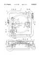
- FIG. 1is a generally perspective, exploded view of one embodiment of the liquid delivery device of the present invention showing an ancillary syringe type device usable for bolus delivery of liquid medication via the bolus injection site of the device.
- FIG. 2is a top plan view of the invention shown in FIG. 1 partly broken away to show internal construction.
- FIG. 3is a cross-sectional view taken along lines 3--3 FIG. 2.
- FIG. 4is an enlarged cross-sectional view taken along lines 4--4 of FIG. 2.
- FIG. 5is a greatly enlarged, cross-sectional view taken along lines 5--5 of FIG. 2.
- FIG. 6is an enlarged, cross-sectional view taken along lines 6--6 of FIG. 2.
- FIG. 7is a greatly enlarged, fragmentary view of the liquid delivery port of the device and of the locking tabs for lockably interconnecting a quick connect delivery fitting with the base of the device.
- FIG. 8is a generally perspective, exploded, view of the liquid delivery port of the device and of an infusion set usable with the device.
- FIG. 9is a cross-sectional view of the quick connect delivery fitting shown in FIG. 8.
- FIG. 9Ais an end view of the quick connect fitting shown in FIG. 9.
- FIG. 10is a greatly enlarged cross-sectional view of the area designated as 10 in FIG. 3.
- FIG. 10Ais a generally perspective, illustrative view showing one manner of filling the fluid reservoir of the device.
- FIG. 10Bis a generally perspective, illustrative view showing the device of the invention attached to the patient and showing the patient engage in injecting a bolus dose of liquid medication.
- FIG. 11is a generally perspective, exploded view of an alternate embodiment of the invention.
- FIG. 12is a top view of the embodiment shown in FIG. 11 partly broken away to show internal construction.
- FIG. 13is a side elevational, partly cross-sectional view taken along lines 13--13 of FIG. 12.
- FIG. 14is a cross-sectional view taken along lines 14--14 of FIG. 13.
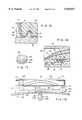
- FIG. 15is a greatly enlarged, fragmentary, cross-sectional view of a portion of the base and cover of the device illustrating the manner in which the distendable membrane and the barrier membrane of the device are sealably clamped between the base and cover.
- FIG. 16is a fragmentary, cross-sectional view of the flow control assembly of the device which is positioned within the base.
- FIG. 17is an enlarged, generally perspective view of the flow control assembly shown in FIG. 16.
- FIG. 18is a front view of yet another form of the fluid delivery device of the invention partly broken away to shown internal construction.
- FIG. 19is a top view of the embodiment shown in FIG. 18 partly broken away to show internal construction.
- FIG. 20is a cross-sectional view taken along lines 20--20 of FIG. 19.
- FIG. 21is a cross-sectional view taken along lines 21--21 of FIG. 19.
- FIG. 21Ais a fragmentary, cross-sectional view taken along lines 21A--21A of FIG. 21.
- FIG. 22is a cross-sectional view taken along lines 22--22 of FIG. 19.
- FIG. 22Ais a cross-sectional view similar to FIG. 22 but showing the fluid being expelled from the fluid reservoir into the body subdermal tissue.
- FIG. 23is a cross-sectional, exploded view of this latest embodiment of the invention.
- FIG. 24is an enlarged, generally perspectives exploded view of the bolus injection port of the device.
- FIG. 25is a generally schematic view illustrating the various modes of operation of the apparatus of the invention.
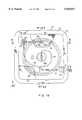
- the devicecomprises a base 12, having an upper surface 14 including a central convex portion 14a and a peripheral portion 14b circumscribing central portion 14a.
- base 12is also provided with a lower surface 16 to which a patient interconnection means or adhesive pad assembly 18 is connected.
- pad assembly 18functions to releasably interconnect the device to the patient so as to hold it securely in place during the liquid delivery step.
- a stored energy meanscooperates with the upper surface 14 of base 12 to form a reservoir 20 having an inlet port 22 which is in communication with a flow passageway 24 which, in turn, communicates with a filling means shown here as a septum assembly 26 (FIGS. 2, 3, and 4).
- the stored energy meansis here provided in the form of at least one distendable membrane 28 which is superimposed over base 12.
- Membrane 28is distendable as a result of pressure imparted on the membrane by fluids "F" introduced into reservoir 20 through inlet port 22 (FIGS. 2 and 3).
- FIG. 3As membrane 28 is distended in the manner shown in FIG. 3, internal stresses will be established, which stresses tend to move the membrane toward a less distended configuration and in a direction toward base 12.
- Membrane 28can be constructed from a single membrane or from multiple membranes to form a laminate construction of the character shown in FIG. 39 of U.S. Pat. No. 5,279,558, which patent is incorporated herein by reference.
- Membrane 39can be formed from a variety of elastomers of the character discussed in detail in U.S. Pat. No. 5,279,558 (see columns 9 and 10 of the patent).
- ullage defining meansfor providing ullage within the reservoir and for engagement with membrane 28 as the membrane moves toward its less distended starting configuration in the manner shown in FIG. 4.
- the ullage defining means in the embodiment of the invention shown in FIGS. 1 through 10comprises the convex central portion 14a of base 12 and defines an engagement surface for engagement by the distendable membrane as the membrane returns to its less distended configuration.
- fluid contained within the reservoir 20will flow through a fluid passageway 21a formed in the convex central portion 21, the base, and thence uniformly outwardly of the reservoir through an outlet port 32. The fluid will then flow into a fluid outlet passageway 34 via flow control means, the character of which will presently be described.
- Base 12 and cover 40can be constructed from a number of different materials of the character described in U.S. Pat. No. 5,279,558 (see columns 9 and 11).
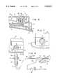
- the infusion means for infusing medicinal fluids from reservoir 20 into the patientcomprises a tapered outlet cavity 46 formed in base 12 (FIG. 6) which sealably receives a quick connect delivery fitting 48 that comprises a part of the infusion means of the invention.
- Fitting 48includes a tapered inboard end portion 48a and a hexagonally shaped body portion 48b.
- a central bore 50extends through portions 48a and 48b and communicates at its outboard end with a cannula 54 which also forms a part of the infusion means of the invention for infusing liquids into the patient.
- the inboard end of bore 50communicates with fluid passageway 34 when fitting 48 is seated within cavity 46 in the manner shown in FIG. 1.
- locking means shown here as resiliently deformable locking tabs 55are provided on base 12 (FIG. 7). Upon pushing inwardly on fitting 48, tabs 55 will separate so that tapered portion 48a of the fitting can be introduced into cavity 46. As the fitting seats within portion 48a, the resiliently deformable locking tabs will close about portion 48b and will engage shoulder 48c in the manner to lockably interconnect the infusion means with the base.
- Filling reservoir 20is accomplished by introducing fluid into the reservoir under pressure via fill means which here comprises a septum assembly 26 mounted in base 12 (FIG. 4).
- Septum assembly 26is of a similar construction to the bolus injection site of the invention, the nature of which will presently be described. More particularly, the septum assembly includes a pierceable septum 26a which is mounted within a tapered cavity 19 formed in base 12.
- Surrounding septum 26ais a generally circularly shaped guide channel 26b.
- fluidcan be introduced into passageway 24 via a pierceable septum 26a which comprises a part of septum assembly 26.
- distendable membrane 28is distended outwardly in the manner shown in FIGS. 3 and 10 and internal stresses are thereby formed in the membrane which tend to urge it toward its less distended starting configuration.
- a mechanical injection pencan also be used to fill the fluid reservoir.
- distendable membrane 28will provide a constant fluid expelling pressure on the fluid contained within the reservoir throughout the fluid delivery cycle, thereby providing precise delivery of liquid medicament over the prescribed delivery period.
- distendable membrane 28can be tailored to provide the desired fluid flow characteristics. (see for example Column 17 of the patent.)
- fluidwill flow from reservoir 20, through outlet port 32, through the previously identified flow control means and then into outlet passageway 34 (FIG.
- the flow control meanswhich further controls the fluid flow characteristics of the device, here comprises an assemblage 36 which is received in a cavity 61 formed in base 12 and which is preferably constructed from a plurality of stacked members 36a, 36b, and 36c.
- Member 36ais a porous member; member 36b is a rate control element; and member 36c is a porous supporting substrate.
- Member 36ais preferably constructed from a material comprising polysulfone sold by Gelman Sciences under the name and style of "SUPOR”.
- Member 36cis preferably constructed from a porous polycarbonate material available from Corning Costar Corporation or from a material sold by DuPont under the name and style KAPTON which has been laser drilled or machined to provide appropriate flow orifices.
- Member 36ccan be constructed from a porous polypropylene.
- bolus injection meanswhich here comprises a bolus injection site mounted in cover 40 and base 12 and generally designated by the numeral 65.
- this novel bolus injection meansincludes a tapered cavity 67 provided in base 12 within which a pierceable septum 70 is mounted.
- a peripheral groove, or guide channel, 72is provided in cover 40 and surrounds septum 70.
- Septum 70is accessible via an opening provided in cover 40 and channel 72 is specially designed to guidably receive a first skirt portion 74a of a novel adapter means or adapter assembly 74 which also comprises a part of the bolus injection means of the invention.
- Adapter assembly 74includes a central body portion 74b which supports a double-ended hollow needle 76.
- needle 76has a pierceable point 76a at one end and a pierceable point 76b at the other end.
- a second internally threaded skirt portion 74cextends from central body portion 74b and surrounds end 76a of needle 76.
- second skirt portion 74cis specially designed to be threadably interconnected with the threaded barrel portion "B" of a syringe shown here as a dose indicating injection pen "IP" of the character disclosed in U.S. Pat. No. 5,226,896 issued to Harris. While any type of conventional syringe assembly having an injection needle can be used to provide the bolus dose via septum 70, the apparatus of the present form of the invention is specially well suited for use with the Harris injection pen. For this reason, the Harris U.S. Pat. No. 5,226,896 is hereby incorporated by reference as through fully set forth herein.
- second skirt 76c of the adapter assemblyis first threadably connected to barrel "B" of the Harris device. During this step, end 76a of the needle will pierce the septum of a medicament vial disposed within the device IP.
- the adapter assemblyis mated with cover 40 by inserting first skirt 74a into groove 72 and then pressing inwardly on the pen to cause needle end 76b to pierce septum 70. This places the bore of the hollow needle in communication with the passageway 34 formed in base 12 and also in communication with bore 50 of fitting 48 of the infusion means. Operation of the injection pen "IP" in the manner described in U.S. Pat. No. 5,226,896 will then cause a bolus dose to enter the infusion means for delivery to the patient.
- the patientcan receive from liquid reservoir 20 a selected basal dose of insulin of, by way of example, one-half milliliter over a 24 hour period.
- a bolus injection of a predetermined volumecan quickly and easily be accomplished through use of the bolus injection means of the invention thereby appropriately supplementing the basal dose being delivered from the fluid reservoir 20.
- a bolus dosecan be introduced into fluid passageway 34 via septum 70. Because of the resistance to upstream flow offered by the rate control means, the bolus dose will flow through passage 34 toward the central bore 50 of quick connect fitting 48 and thence into delivery line 54. Interconnected with line 54 is a soft cannula assembly 80 (FIG. 8), the operation of which is well understood by those skilled in the art.
- the cannula insertion assembly 82which includes a trocar 82a can be removed, leaving the soft cannula 80a in position within the patient.
- Needle cannula interconnect 84a of the connector assembly 84 of the infusion setcan then be inserted into assembly 80 and interconnect therewith using the conventional latch mechanism 85.
- Connector assembly 84which also forms a part of the infusion means, when connected to assembly 80, places soft cannula 80a in fluid communication with reservoir 20.
- the infusion set of this form of the inventionwhich comprises line 54, connector assembly 84, and soft cannula assembly 80, is of a character well known in the art and is readily available from several commercial sources including Pharma-Plast International A/S of Lynge, Denmark.
- the injection pen IPcan effectively be used to provide the bolus dose delivery when the device of the invention is affixed to the patient's body as, for example, a location proximate the patient's waist. Due to the novel design of the skirt portion 74a of the adapter assembly 74, the injection pen can be easily mated with device 10 by simply inserting the skirt portion into the circular guide channel or groove 72.
- the injection pen IPcan also be conveniently used to fill the fluid reservoir of the device via filling septum 26a while being held in the user's hand.
- skirt portion 74ais guidably received within guide channel 26b formed as a part of septum assembly 26 (see also FIG. 4).
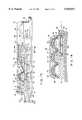
- FIGS. 11 through 17still another form of the fluid delivery device of the invention is there shown and generally designated by the numeral 90.
- this latest embodiment of the inventionis similar in some respects to that shown in FIGS. 1 through 10. Accordingly, like numbers are used to describe like components.
- this latest embodiment of the inventionis unique in that it includes dual reservoirs which communicate with the infusion means of this latest embodiment of the invention.
- the embodiment of the invention there showncomprises a base 92 having an upper surface 94 including a central portion 94a and a peripheral portion 94b circumscribing central portion 94a.
- Base 92is also provided with a lower surface 96.
- Formed within base 92is a fluid passageway 100 (FIG. 12), which communicates with a tapered wall, cavity 102 provided in base 92, which cavity sealably receives portion 104a of a quick connect delivery fitting assembly 104 which is somewhat similar to fitting 48 as previously described.
- the apparatus shown in FIGS. 11 through 17includes stored energy means for forming, in conjunction with the base 92 a pair of reservoirs 106 and 108 having outlets 110 and 112 respectively (FIG. 13)
- outlet 110is in communication with a first inlet passageway 114 leading to passageway 100
- outlet 112is in communication with a second inlet passageway 116 leading to passageway 100.
- Filling of central or inner reservoir 106is accomplished via fill means here comprising a first septum assembly 118 while filling of outer or toroidal reservoir 108 is accomplished via a second fill means or second septum assembly 120.
- Both septum assembliesinclude a pierceable septum 119 (FIG. 14) which is pierceable by a needle of a conventional syringe.
- the stored energy meansis provided in the form of at least one distendable membrane 122 which is superimposed over base 92.
- An ullage defining meansis disposed within a central chamber portion 124 formed in a cover 126 for forming ullage within the chamber.
- an ullage defining meansis disposed within a peripheral chamber portion 130 formed in cover 126 each of the central chambers for forming ullage within the toroidal chamber.
- the ullage meansinteract with membrane 122 which, after being distended, will tend to return to its less distended configuration.
- the ullage defining means of this latest embodiment of the inventioncomprises conformable masses 134 and 136 which uniquely conform to the continuously changing shape of the distendable membrane as the membrane tends to return to its less distended configuration.
- the first conformable mass 134is disposed within chamber 124, while the second conformable mass 136 is disposed within chamber 130.
- the ullage defining means, or flowable masses 134 and 136are preferably constructed from materials such as gels, foams, fluids and soft elastomers. More particularly, materials particularly well suited for constructing the conformable masses include oil, gaseous materials, various polymers and various viscous liquids. Additionally, those masses can be formed from sodium palmitate, sodium sterate and methyl cellulose. Where, as is here the case, the conformable ullage comprises a gel, a yieldable encapsulation barrier means or membrane 140 is used to encapsulate the conformable masses 134 and 136 between the distendable membrane and the barrier membrane. With this construction, the conformable ullages are located between the barrier membrane 140 and the distendable membrane 122. Barrier membrane 140 can be constructed from various materials including polyurethane, polypropylene, polyethylene and fluorosilicon.
- the peripheral portion of the cover 126is provided with a capture groove 142 and an adjacent tongue 144.
- base 92is provided with tongue 146 which mates with groove 142 as the cover moves into engagement with base 92.
- Base 92is further provided with an upstanding membrane cutting means, or protuberance 147 which functions to cleanly cut the stored energy means and barrier membrane 140 upon cover 126 being brought into pressural engagement with base 92.
- central reservoircan be filled via septum assembly 118 and passageway 118a using a conventional fluid containing syringe assembly having needle adapted to penetrate septum 119 of septum assembly 118.
- toroidal reservoir 108can be filled via septum assembly 120 and passageway 120a using a second syringe assembly containing a second fluid either the same as or different from the first fluid used to fill chamber 106. Fluids flowing into the reservoirs are filtered by filter means shown in FIG. 14 as filter elements 157. With the chambers filled, and the quick connect delivery fitting assembly 104 connected to base 92, the device is in condition for the liquid delivery step. As seen in FIG.
- the quick connect delivery fitting assemblyis of slightly different construction, as is the outlet port assembly of the device. More particularly, the outlet port housing 154, within which tapered portion 102 is formed, extends outwardly from the base and is provided with a circumferentially extending locking groove 156 which forms a part of the infusion set locking means of this form of the invention.
- Fitting assembly 157also includes a pair of spaced-apart locking arms 158 which terminate at their inboard ends in hook-like extremities 158a which are receivable within groove 156. By pressing inwardly on the rearwardly extending portions 158b of arms 158, extremities 158a will pivot about a collar 158 carried by the fitting and will resiliently spread apart to permit their release from normal biased engagement with groove 156.
- the base of the deviceis provided with a suitable adhesive to enable the device to be removably affixed to the patient's body such as to the arm or leg of the patient.
- first or central chamber 106 and within toroidal chamber 108will be urged to flow through fluid passageway 100 as the stored energy means, or distendable membrane 122 tends to return to its less distended configuration.
- the conformable ullages contained within the reservoirswill closely conform to the changing geometry of the stored energy means as the stored energy means moves toward base 92.
- the flow control meanshere comprises a pair of assemblies each being of the character shown in FIG. 17. Each assembly is receivable within a cavity provided in the base. More particularly, assemblage 160 is mounted within a cavity 162 provided in the central portion of the base while assembly 164 is mounted within a cavity 166 provided in the peripheral portion of the base. As shown in FIG. 17, each assemblage 160 and 162 is of a laminate construction comprising filtering means for filtering the fluid flowing outwardly of the reservoirs and rate control means for controlling the rate of fluid flow from the reservoirs into passageway 100. Referring to FIG. 17, it can be seen that the filter means comprises disk-like filter element 160a while the rate control element comprises a disk-like rate control element 160b.
- filter element 160aSuperimposed over filter element 160a is a porous disk-like support substrate 160c.
- the assemblagecomprising filter element 160a, rate control element 160b and porous substrate 160c is supported in base 92 in the manner shown in FIG. 16.
- Filter element 160acan be constructed from a wide variety of materials. However, a material comprising polysulfone sold by Gelman Sciences under the name and style of SUPOR has proven satisfactory.
- Rate control element 160bis preferably constructed from a polycarbonate material having extremely small flow apertures ablatively drilled by an excimer laser ablation process. Both the orifice size and unit distribution can be closely controlled by this process. However, a number of other methods can also be used to construct this element.
- Porous substrate 160ccan similarly be constructed from various materials such as a porous polypropylene available from Gelman Sciences.
- the latest embodiment of the inventionalso includes bolus injection means comprising a bolus injection site 65, which is identical in construction and operation to that previously described.
- the bolus injection meansincludes a pierceable septum 70 which is accessible through the cover of the device and also includes a guide channel 72 which permits easy mating of the previously described adapter assembly 74.
- liquids introduced via septum 70will flow into a passageway 100a which communicates with outlet passageway 100, thereby permitting delivery to the patient of bolus doses of medication via the infusion means of the device.
- FIGS. 18 through 24yet another form of the fluid delivery device of the invention is there shown and generally designated by the numeral 170.
- the devicehere comprises a base 172, having an upper surface 174 including a central portion 174a and a peripheral portion 174b circumscribing central portion 174a.
- base 172is also provided with a lower surface 176 to which a patient interconnection means or adhesive pad assembly 178 is connected.
- pad assembly 178functions to releasably interconnect the device to the patient so as to hold it securely in place during the delivery step.
- a stored energy meanscooperates with the upper surface 174 of base 172 to form a reservoir 180 having an inlet port 182 which is in communication with a flow passageway 184 which, in turn communicates with a filling means shown here as a septum assembly 186 (FIGS. 18, 19, and 20).
- the stored energy meansis here provided in the form of at least one distendable membrane 188 which is superimposed over base 172.
- Membrane 188is distendable as a result of pressure imparted on the membrane by fluids "F" introduced into reservoir 180 through inlet port 182 (FIG. 22). As membrane 188 is distended in the manner shown in FIG.
- Membrane 188is substantially identical to membrane 28 (FIG. 3) and can be constructed from a single membrane or from multiple membranes to form a laminate construction.
- ullage defining meansfor providing ullage within the reservoir and for engagement with membrane 188 as the membrane moves toward its less distended starting configuration.
- the ullage defining means provided in this latest embodiment of the inventioncomprises a conformable mass 190 which is engageable by the distendable membrane as the membrane returns to its less distended configuration.
- Conformable mass 190is of a character similar to the conformable masses that make up the ullage defining means of the form of the invention shown in FIGS. 11 through 17.
- fluid contained within the reservoir 180will flow uniformly outwardly of the reservoir through an outlet port 180a and into a fluid outlet passageway 230 via flow control means generally designated by the numeral 224 (FIG. 22A).
- cover meansSuperimposed over base 172 is the cover means, shown here as a rigid cover, which functions, through the use of novel sealing means, to sealably enclose membrane 188.
- the sealing meanshere comprises a circular groove 175 formed in peripheral surface 174b of base 172 and a circular rim like protuberance 200a formed on the lower surface of cover 200.
- Protuberance 200ais receivable within groove 175 and functions to sealably clamp distendable membrane 188 between the cover and the base in the manner shown in FIGS. 20 and 22.
- a medicament and use label 41can be affixed to cover 200 in the manner previously described and as shown in FIG. 1.
- base 172 and cover 200can be constructed from a variety of materials of the character described in U.S. Pat. No. 5,279,558.
- the infusion means of this latest form of the invention for subdermal infusion of medicaments into the patientis of a highly novel construction. More particularly, the infusion means here comprises a circuitous shaped hollow cannula 206 which is carried within a circuitous channel 208, formed in the intermediate body portion 172i of base 172.
- Cannula 206includes a body portion 206a which is mounted within channel 208 and also includes an outlet end 206b, here provided in the form of a needle-like segments which extends generally perpendicularly downward from the lower surface of base 172.
- circuitous body portion 206a, of the cannulawhen mounted within channel 208, provides an extremely strong and rigid structure that effectively prevents bending or breakage of the small diameter cannula. So that outlet end 206b can easily penetrate the patient's skin and tissue "ST" for subdermal penetration (see FIG. 22A), end 206b is provided with a sharp, pointed extremity 206c (FIGS. 22 and 22A).
- a protective cover assembly 210surrounds these portions of the cannula.
- the skirt portion 210a of the protective cover 210can be readily separated from the base by breaking it away along a serration line 211 formed between the skirt portion 210a and a disk like base portion 210b.
- Skirt portion 210ais configured to receive a plug 210p which provides a sterile barrier and prevents premature fluid flow from end 206c of the cannula.
- Base portion 210bis provided with an upstanding circumferentially extending rim 210c which is receivable within a cylindrically shaped cavity 214 provided in base 172 (see FIG. 22). Disk-like base portion 210b is also receivable within an aperture 178a provided in pad assembly 178 (FIG. 23).
- Filling of reservoir 180is accomplished by introducing fluid into the reservoir under pressure via a septum assembly 186 which is mounted in base 172 (FIG. 18).
- a septum assembly 186which is mounted in base 172 (FIG. 18).
- fluidcan be introduced into passageway 184 via a pierceable septum 186a which comprises a part of septum assembly 186.
- a barrier means or barrier membrane 217is distended outwardly against the conformable mass 190 controllably moving it along with a distendable membrane 188 toward cover 200.
- distendable membrane 188will engage surface 219 formed in cover 200, and the ullage defining means will uniquely conform to surface 219a as well as to the varying shape of distendable membrane 188.
- any gases contained within the reservoirwill be vented to atmosphere via vent means, shown here as a vent plug 221.
- Barrier membrane 217can be constructed from the various materials previously described.
- the conformable formable ullageWhen the fluid is dispensed from the device, the conformable formable ullage will permit the distendable membrane to provide a constant fluid expelling pressure on the fluid contained within the reservoir throughout the fluid delivery cycle, thereby avoiding undesirable delivery rate tail off at the end of the delivery period.
- This novel substantially linear performancepermits the device to meet even the most stringent of delivery protocals.
- fluidwill flow from reservoir 180 through outlet port 192, through the flow control means, and then, in a manner presently to be described into cannula 206.
- the flow control means of this latest form of the inventioncomprises an assemblage 224 which is received in a cavity 225 formed in the high novel fusion means of the present invention, the character of which will presently be described.
- Assemblage 224comprises a first wafer 224a which functions as a filter means of the character previously described.
- Wafer 224bis preferably constructed from a hydrogel rate control medium which, upon imbibing fluid, swells into a cavity provided in the filter. Upon swelling into a known configuration, wafer 224b will function to provide a specific permeability thereby precisely controlling the rate of fluid flow from the reservoir 180.
- Wafer 224cfunctions as a support substrate for the assemblage.
- This infusion meansincludes the previously identified circuitous shaped cannula 206, the inlet end 206i of which is connected to a hollow housing 226 that is mounted in base 172 in the manner best seen in FIG. 21.
- Inlet end 206i of the cannulacommunicates with a chamber 226a formed in housing 226 as does the outlet end 230a of a hollow tube 230.
- the inlet end 230b of tube 230is connected to a second hollow housing 232 which is mounted in base 172 and within which the previously identified cavity 225 is formed.
- tube 230places the outlet 180a of reservoir 180 in fluid communication with chamber 226a of housing 226 and also in fluid communication with cannula 206 via an inlet port 234 which is disposed within chamber 226a. Accordingly, fluid can flow from reservoir 180 into chamber 225 via the flow control means, then into tube 230 and finally into cannula 206 for subdermal delivery to the patient.
- a bolus injection meanswhich here forms a part of the infusion means of the invention and includes a bolus injection site which is accessible through cover 200.
- this novel bolus injection meansis similar to that previously described but includes the earlier identified hollow housing 226 within which a pierceable septum 236 is mounted in the manner shown in FIG. 21. Septum 236 is held in place within cover 200 by a retainer cap 237. A peripheral groove 238 surrounds retainer cap 237 and is specifically designed to receive the first skirt portion 74a of the previously described adapter means or adapter assembly 74.
- Adapter assembly 74is of identical construction and operation to that described in connection with the embodiment of the invention shown in FIGS. 1 through 10 and serves to deliver a bolus dose of medicinal fluid into chamber 226a of hollow housing 226 and thence into cannula 206 via inlet 234.
- adapter assembly 74is specially designed to be threadably interconnected with the dose indicating injection pen "IP" of the character disclosed in U.S. Pat. No. 5,226,896 issued to Harris.
- the patientcan continually receive a selected basal dose of liquid medication, such as insulin from reservoir 180.
- a basal dose of liquid medicationsuch as insulin from reservoir 180.
- a bolus injection of a predetermined volumecan quickly and easily be administered through use of the novel bolus injection means of the invention and in this way appropriately supplement the basal dose being delivered from reservoir 180.
- FIG. 25several fluid delivery regimens are there illustrated.
- a fluid delivery device 250having a fluid reservoir 252 with a volume V-1 is used to accomplish delivery of a liquid medicament such as insulin.
- the medicamentis delivered to the patient through an appropriate infusion means which includes a delivery line 253 and a flow rate control means designated as R-1.
- Reservoir 252can be filled using a filling means here shown as a septum assembly S-1.
- medicinal liquidscan be delivered to the patient at a fixed rate over time with the rate of delivery being governed by the character of the flow rate control means R-1.
- a fluid delivery device 254 having a fluid reservoir 252 with a volume V-1is there shown.
- fluidcan be delivered to the patient at a basal rate via a delivery line 255 and a flow rate control means designated as R-1.
- Reservoir 252can, once again, be filled by a fill means shown here is a septum assembly S-1.
- a bolus dose delivery meansgenerally designated as S-2. This bolus dose delivery means, which can be of the character illustrated and described in connection with the embodiment of the invention shown in FIGS.
- Device 254exemplifies the types of single reservoir devices of the invention illustrated in FIGS. 1 through 10 and in FIGS. 18 through 24 of the drawings.
- a delivery device 256is there provided. Unlike delivery devices 250 and 254, device 256 includes dual fluid reservoirs 252 and 258. As before, reservoir 252 has a volume V-1, while second reservoir 258 has a volume V-2. Reservoir 252 can be filled by septum assembly S-1 while reservoir 258 can be filled using a septum assembly S-2. Reservoir 252 communicates with the patient via a delivery line 257 and a first flow rate control means R-1, while reservoir 258 communicates with the patient via a delivery line 259 and a second flow rate control means designated as R-2. For reasons presently to be described, this arrangement is ideally for delivering liquid medicaments such as insulin.
- insulincan be delivered to the patient via delivery line 261 with insulin flowing simultaneously from both reservoirs 252 and 258.
- the amount of fluid being delivered from each of the reservoirsis, of course, determined by the character of the flow rate control device which is interconnected with that reservoir.
- flow rate control means R-2because of the greater resistance offered by flow rate control means R-2, during the night insulin will continue to flow to the patient from reservoir 258 but at a lesser rate than the daytime basal delivery rate once again, by properly selecting the flow rate control means R-2, insulin can be delivered to the patient at a prescribed basal delivery rate from reservoir 258 throughout the entire nighttime hours.
- a single dual reservoir fluid delivery devicecan be used to provide a precise basal delivery of insulin to the patient over an entire 24-hour period.
- a bolus dose delivery meansdesignated as S-3.
- This important bolus delivery meanspermits the patient to introduce into delivery line 261 via S-3 a bolus dose of insulin at any time the patient discovers that his or her blood sugar level is too high.
- this latest arrangement as shown in FIG. 25,is exemplified by the dual reservoir embodiment of the invention which is illustrated in FIGS. 11 through 17 of the drawings.
Landscapes
- Health & Medical Sciences (AREA)
- Engineering & Computer Science (AREA)
- Public Health (AREA)
- Life Sciences & Earth Sciences (AREA)
- Veterinary Medicine (AREA)
- Anesthesiology (AREA)
- Biomedical Technology (AREA)
- Heart & Thoracic Surgery (AREA)
- Hematology (AREA)
- General Health & Medical Sciences (AREA)
- Animal Behavior & Ethology (AREA)
- Vascular Medicine (AREA)
- Bioinformatics & Cheminformatics (AREA)
- Chemical & Material Sciences (AREA)
- Medicinal Chemistry (AREA)
- Infusion, Injection, And Reservoir Apparatuses (AREA)
Abstract
Description
Claims (21)
Priority Applications (1)
| Application Number | Priority Date | Filing Date | Title |
|---|---|---|---|
| US08/991,121US5925017A (en) | 1995-10-11 | 1997-12-16 | Fluid delivery device with bolus injection site |
Applications Claiming Priority (2)
| Application Number | Priority Date | Filing Date | Title |
|---|---|---|---|
| US08/541,184US5776103A (en) | 1995-10-11 | 1995-10-11 | Fluid delivery device with bolus injection site |
| US08/991,121US5925017A (en) | 1995-10-11 | 1997-12-16 | Fluid delivery device with bolus injection site |
Related Parent Applications (1)
| Application Number | Title | Priority Date | Filing Date |
|---|---|---|---|
| US08/541,184DivisionUS5776103A (en) | 1995-10-11 | 1995-10-11 | Fluid delivery device with bolus injection site |
Publications (1)
| Publication Number | Publication Date |
|---|---|
| US5925017Atrue US5925017A (en) | 1999-07-20 |
Family
ID=24158522
Family Applications (2)
| Application Number | Title | Priority Date | Filing Date |
|---|---|---|---|
| US08/541,184Expired - Fee RelatedUS5776103A (en) | 1995-10-11 | 1995-10-11 | Fluid delivery device with bolus injection site |
| US08/991,121Expired - Fee RelatedUS5925017A (en) | 1995-10-11 | 1997-12-16 | Fluid delivery device with bolus injection site |
Family Applications Before (1)
| Application Number | Title | Priority Date | Filing Date |
|---|---|---|---|
| US08/541,184Expired - Fee RelatedUS5776103A (en) | 1995-10-11 | 1995-10-11 | Fluid delivery device with bolus injection site |
Country Status (7)
| Country | Link |
|---|---|
| US (2) | US5776103A (en) |
| EP (1) | EP0957955A1 (en) |
| JP (1) | JP2001515371A (en) |
| AU (1) | AU719738B2 (en) |
| BR (1) | BR9610764A (en) |
| CA (1) | CA2234581A1 (en) |
| WO (1) | WO1997013544A1 (en) |
Cited By (98)
| Publication number | Priority date | Publication date | Assignee | Title |
|---|---|---|---|---|
| RU2170107C1 (en)* | 2000-07-21 | 2001-07-10 | Общество с ограниченной ответственностью Научно-технический центр "Мепотекс" | Apparatus for introducing liquid into individual's organism |
| WO2002068013A3 (en)* | 2000-12-18 | 2002-10-24 | Science Inc | Multiple canopy |
| US20030208184A1 (en)* | 2000-01-11 | 2003-11-06 | Paul Burke | Implantable, refillable infusion device and spetum replacement kit |
| WO2003068294A3 (en)* | 2002-02-18 | 2003-12-31 | Danfoss As | Device for administering of medication in fluid form |
| US20040002693A1 (en)* | 2002-06-26 | 2004-01-01 | Bright Jeffrey D. | Implantable pump connector for catheter attachment |
| US20040006316A1 (en)* | 2002-07-02 | 2004-01-08 | Patton Catherine C. | Infusion device and method thereof |
| US20050033233A1 (en)* | 2003-08-04 | 2005-02-10 | Kriesel Marshall S. | Infusion apparatus with constant force spring energy source |
| US20050033232A1 (en)* | 2003-08-05 | 2005-02-10 | Kriesel Marshall S. | Infusion apparatus with modulated flow control |
| US20050263615A1 (en)* | 2004-05-26 | 2005-12-01 | Kriesel Marshall S | Fluid delivery apparatus with adjustable flow rate control |
| US20050277883A1 (en)* | 2004-05-26 | 2005-12-15 | Kriesel Marshall S | Fluid delivery device |
| US20050277884A1 (en)* | 2004-05-26 | 2005-12-15 | Kriesel Marshall S | Fluid delivery apparatus with bellows reservoir |
| US20050277882A1 (en)* | 2004-05-26 | 2005-12-15 | Kriesel Marshall S | Infusion apparatus |
| US20060071833A1 (en)* | 2004-09-16 | 2006-04-06 | Sony Corporation | Digital signal processing apparatus and digital signal processing method |
| US20060095014A1 (en)* | 2003-05-08 | 2006-05-04 | Novo Nordisk A/S | External inserter for transcutaneous device |
| US20060106362A1 (en)* | 2002-11-01 | 2006-05-18 | Franklin Pass | Administration of insulin by jet injection |
| US20060122562A1 (en)* | 2004-11-19 | 2006-06-08 | Mckinley Medical L.L.L.P. | Controlled-volume infusion device |
| WO2006061354A1 (en)* | 2004-12-06 | 2006-06-15 | Novo Nordisk A/S | Ventilated skin mountable device |
| US20060142698A1 (en)* | 2003-05-08 | 2006-06-29 | Novo Nordisk A/S | Internal needle inserter |
| US20060195057A1 (en)* | 2005-02-18 | 2006-08-31 | Kriesel Marshall S | Fluid delivery apparatus with vial fill |
| US20060196552A1 (en)* | 2005-02-17 | 2006-09-07 | Kriesel Marshall S | Distal rate control device |
| US20060206052A1 (en)* | 2005-02-15 | 2006-09-14 | Kriesel Marshall S | Fluid delivery and mixing apparatus with flow rate control |
| US20070021733A1 (en)* | 2003-10-21 | 2007-01-25 | Novo Nordisk A/S | Internal fluid connector |
| US7169128B2 (en) | 2003-08-04 | 2007-01-30 | Bioquiddity, Inc. | Multichannel fluid delivery device |
| US20070049865A1 (en)* | 2003-08-01 | 2007-03-01 | Novo Nordisk A/S | Retraction means for transcutaneous device |
| US20070104596A1 (en)* | 2004-03-30 | 2007-05-10 | Novo Nordisk A/S | Actuator system comprising lever mechanism |
| US20070135774A1 (en)* | 2005-11-03 | 2007-06-14 | Patton Medical Devices, Lp | Fluid delivery devices, systems and methods |
| US20070156090A1 (en)* | 2004-05-26 | 2007-07-05 | Kriesel Marshall S | Fluid delivery apparatus |
| US20070219501A1 (en)* | 2006-03-15 | 2007-09-20 | Kriesel Marshall S | Fluid dispensing apparatus |
| US20080009835A1 (en)* | 2005-02-17 | 2008-01-10 | Kriesel Marshall S | Fluid dispensing apparatus with flow rate control |
| US20080021375A1 (en)* | 2005-08-22 | 2008-01-24 | John Burns | Fluid Delivery Devices, Systems and Methods |
| US20080027376A1 (en)* | 2006-07-31 | 2008-01-31 | Kriesel Marshall S | Fluid dispensing device with additive |
| AT503144B1 (en)* | 2006-02-08 | 2008-02-15 | Pro Med Medizinische Produktio | DEVICE FOR DOSED DISPENSING OF LIQUID |
| US20080167641A1 (en)* | 2005-05-13 | 2008-07-10 | Novo Nordisk A/S | Medical Device Adapted To Detect Disengagement Of A Transcutaneous Device |
| US20080183898A1 (en)* | 2007-01-31 | 2008-07-31 | International Business Machines Corporation | Channel subsystem server time protocol commands and system therefor |
| US20080215006A1 (en)* | 2004-09-22 | 2008-09-04 | Novo Nordisk A/S | Medical Device with Transcutaneous Cannula Device |
| US20080243077A1 (en)* | 2007-04-02 | 2008-10-02 | Bivin Donald B | Fluid dispenser with uniformly collapsible reservoir |
| US20080319385A1 (en)* | 2007-06-25 | 2008-12-25 | Kriesel Marshall S | Fluid dispenser with additive sub-system |
| US20090012472A1 (en)* | 2004-09-22 | 2009-01-08 | Novo Nordisk A/S | Medical Device with Cannula Inserter |
| US20090024083A1 (en)* | 2007-06-25 | 2009-01-22 | Kriesel Marshall S | Fluid dispenser with additive sub-system |
| US20090076451A1 (en)* | 2005-01-24 | 2009-03-19 | Nova Nordisk A/S | Medical Device with Protected Transcutaneous Device |
| US20090163874A1 (en)* | 2006-04-26 | 2009-06-25 | Novo Nordisk A/S | Skin-Mountable Device in Packaging Comprising Coated Seal Member |
| US20100063448A1 (en)* | 2007-03-06 | 2010-03-11 | Novo Nordisk A/S | Pump assembly comprising actuator system |
| WO2010085338A1 (en)* | 2009-01-21 | 2010-07-29 | Becton, Dickinson And Company | Infusion set |
| US7785302B2 (en) | 2005-03-04 | 2010-08-31 | C. R. Bard, Inc. | Access port identification systems and methods |
| US7828772B2 (en) | 2006-03-15 | 2010-11-09 | Bioquiddity, Inc. | Fluid dispensing device |
| US20110008206A1 (en)* | 2007-10-31 | 2011-01-13 | Novo Nordisk A/S | Non-Porous Material as Sterilization Barrier |
| US20110060289A1 (en)* | 2003-05-08 | 2011-03-10 | Novo Nordisk A/S | Integrated package |
| US7947022B2 (en) | 2005-03-04 | 2011-05-24 | C. R. Bard, Inc. | Access port identification systems and methods |
| US20110160696A1 (en)* | 2009-12-31 | 2011-06-30 | Abbott Diabetes Care Inc. | Injection port device adapted for use with insulin pump |
| US8025639B2 (en) | 2005-04-27 | 2011-09-27 | C. R. Bard, Inc. | Methods of power injecting a fluid through an access port |
| US8029482B2 (en) | 2005-03-04 | 2011-10-04 | C. R. Bard, Inc. | Systems and methods for radiographically identifying an access port |
| US8057435B2 (en) | 2006-07-31 | 2011-11-15 | Kriesel Joshua W | Fluid dispenser |
| US8177762B2 (en) | 1998-12-07 | 2012-05-15 | C. R. Bard, Inc. | Septum including at least one identifiable feature, access ports including same, and related methods |
| US8202259B2 (en) | 2005-03-04 | 2012-06-19 | C. R. Bard, Inc. | Systems and methods for identifying an access port |
| US8257325B2 (en) | 2007-06-20 | 2012-09-04 | Medical Components, Inc. | Venous access port with molded and/or radiopaque indicia |
| USD676955S1 (en) | 2010-12-30 | 2013-02-26 | C. R. Bard, Inc. | Implantable access port |
| USD682416S1 (en) | 2010-12-30 | 2013-05-14 | C. R. Bard, Inc. | Implantable access port |
| US8641676B2 (en) | 2005-04-27 | 2014-02-04 | C. R. Bard, Inc. | Infusion apparatuses and methods of use |
| US8715244B2 (en) | 2009-07-07 | 2014-05-06 | C. R. Bard, Inc. | Extensible internal bolster for a medical device |
| USD709767S1 (en) | 2013-03-14 | 2014-07-29 | Becton, Dickinson And Company | Package portion for a medical product |
| US8915889B2 (en) | 2008-08-05 | 2014-12-23 | Antares Pharma, Inc. | Multiple dosage injector |
| US8932271B2 (en) | 2008-11-13 | 2015-01-13 | C. R. Bard, Inc. | Implantable medical devices including septum-based indicators |
| US8945063B2 (en) | 2009-03-20 | 2015-02-03 | Antares Pharma, Inc. | Hazardous agent injection system |
| US8945071B2 (en) | 2010-09-02 | 2015-02-03 | Becton, Dickinson And Company | Self-injection device having needle cover with activation preventer |
| US8961469B2 (en) | 2009-12-16 | 2015-02-24 | Becton, Dickinson And Company | Self-injection device |
| US9079004B2 (en) | 2009-11-17 | 2015-07-14 | C. R. Bard, Inc. | Overmolded access port including anchoring and identification features |
| US9173992B2 (en) | 2006-03-13 | 2015-11-03 | Novo Nordisk A/S | Secure pairing of electronic devices using dual means of communication |
| US9180259B2 (en) | 2005-01-24 | 2015-11-10 | Antares Pharma, Inc. | Prefilled syringe jet injector |
| US9211378B2 (en) | 2010-10-22 | 2015-12-15 | Cequr Sa | Methods and systems for dosing a medicament |
| US9220660B2 (en) | 2011-07-15 | 2015-12-29 | Antares Pharma, Inc. | Liquid-transfer adapter beveled spike |
| US9265912B2 (en) | 2006-11-08 | 2016-02-23 | C. R. Bard, Inc. | Indicia informative of characteristics of insertable medical devices |
| US9333309B2 (en) | 2002-02-11 | 2016-05-10 | Antares Pharma, Inc. | Intradermal injector |
| US9364611B2 (en) | 2012-05-07 | 2016-06-14 | Antares Pharma, Inc. | Needle assisted jet injection device having reduced trigger force |
| US9399094B2 (en) | 2006-06-06 | 2016-07-26 | Novo Nordisk A/S | Assembly comprising skin-mountable device and packaging therefore |
| US9440024B2 (en) | 2009-01-27 | 2016-09-13 | Becton, Dickinson And Company | Infusion set with anesthetic compound |
| US9446195B2 (en) | 2011-07-15 | 2016-09-20 | Antares Pharma, Inc. | Injection device with cammed ram assembly |
| US9474888B2 (en) | 2005-03-04 | 2016-10-25 | C. R. Bard, Inc. | Implantable access port including a sandwiched radiopaque insert |
| US9517329B2 (en) | 2007-07-19 | 2016-12-13 | Medical Components, Inc. | Venous access port assembly with X-ray discernable indicia |
| US9555187B2 (en) | 2009-12-16 | 2017-01-31 | Becton, Dickinson And Company | Self-injection device |
| US9579461B2 (en) | 2009-12-16 | 2017-02-28 | Becton, Dickinson And Company | Self-injection device |
| US9579496B2 (en) | 2007-11-07 | 2017-02-28 | C. R. Bard, Inc. | Radiopaque and septum-based indicators for a multi-lumen implantable port |
| US9610432B2 (en) | 2007-07-19 | 2017-04-04 | Innovative Medical Devices, Llc | Venous access port assembly with X-ray discernable indicia |
| US9642986B2 (en) | 2006-11-08 | 2017-05-09 | C. R. Bard, Inc. | Resource information key for an insertable medical device |
| US9707354B2 (en) | 2013-03-11 | 2017-07-18 | Antares Pharma, Inc. | Multiple dosage injector with rack and pinion dosage system |
| US9717850B2 (en) | 2009-12-16 | 2017-08-01 | Becton, Dickinson And Company | Self-injection device |
| US9744302B2 (en) | 2013-02-11 | 2017-08-29 | Antares Pharma, Inc. | Needle assisted jet injection device having reduced trigger force |
| US9808582B2 (en) | 2006-05-03 | 2017-11-07 | Antares Pharma, Inc. | Two-stage reconstituting injector |
| US9833562B2 (en) | 2009-12-16 | 2017-12-05 | Becton, Dickinson And Company | Self-injection device |
| US9943641B2 (en) | 2013-03-14 | 2018-04-17 | Becton, Dickinson And Company | Package for medical product |
| US9950125B2 (en) | 2012-04-06 | 2018-04-24 | Antares Pharma, Inc. | Needle assisted jet injection administration of testosterone compositions |
| US10195340B2 (en) | 2009-12-16 | 2019-02-05 | Becton, Dickinson And Company | Self-injection device |
| US10307581B2 (en) | 2005-04-27 | 2019-06-04 | C. R. Bard, Inc. | Reinforced septum for an implantable medical device |
| US10463845B2 (en) | 2013-01-23 | 2019-11-05 | C.R. Bard, Inc. | Low-profile access port |
| USD870264S1 (en) | 2017-09-06 | 2019-12-17 | C. R. Bard, Inc. | Implantable apheresis port |
| US11420033B2 (en) | 2013-01-23 | 2022-08-23 | C. R. Bard, Inc. | Low-profile single and dual vascular access device |
| US11464960B2 (en) | 2013-01-23 | 2022-10-11 | C. R. Bard, Inc. | Low-profile single and dual vascular access device |
| US11654221B2 (en) | 2003-11-05 | 2023-05-23 | Baxter International Inc. | Dialysis system having inductive heating |
| US11890443B2 (en) | 2008-11-13 | 2024-02-06 | C. R. Bard, Inc. | Implantable medical devices including septum-based indicators |
Families Citing this family (122)
| Publication number | Priority date | Publication date | Assignee | Title |
|---|---|---|---|---|
| US6210361B1 (en) | 1997-08-22 | 2001-04-03 | Deka Products Limited Partnership | System for delivering intravenous drugs |
| US5776103A (en)* | 1995-10-11 | 1998-07-07 | Science Incorporated | Fluid delivery device with bolus injection site |
| US5957891A (en)* | 1995-10-11 | 1999-09-28 | Science Incorporated | Fluid delivery device with fill adapter |
| US5807335A (en)* | 1995-12-22 | 1998-09-15 | Science Incorporated | Fluid delivery device with conformable ullage and fill assembly |
| US5957895A (en) | 1998-02-20 | 1999-09-28 | Becton Dickinson And Company | Low-profile automatic injection device with self-emptying reservoir |
| EP1082151A1 (en)* | 1998-06-04 | 2001-03-14 | ELAN CORPORATION, Plc | Gas driven drug delivery device |
| US6447891B1 (en) | 1999-05-03 | 2002-09-10 | Guardian Industries Corp. | Low-E coating system including protective DLC |
| US6485461B1 (en) | 2000-04-04 | 2002-11-26 | Insulet, Inc. | Disposable infusion device |
| US6702779B2 (en)* | 2000-08-18 | 2004-03-09 | Becton, Dickinson And Company | Constant rate fluid delivery device with selectable flow rate and titratable bolus button |
| CA2421133C (en) | 2000-09-08 | 2012-06-26 | Insulet Corporation | Devices, systems and methods for patient infusion |
| US6669669B2 (en)* | 2001-10-12 | 2003-12-30 | Insulet Corporation | Laminated patient infusion device |
| ES2281457T3 (en) | 2000-11-09 | 2007-10-01 | Insulet Corporation | TRANSCUTANEOUS SUPPLY MEDIA. |
| AU2002239709B2 (en) | 2000-12-21 | 2007-02-15 | Insulet Corporation | Medical apparatus remote control and method |
| EP1381408A4 (en) | 2001-02-22 | 2007-06-13 | Insulet Corp | Modular infusion device and method |
| US20040078028A1 (en)* | 2001-11-09 | 2004-04-22 | Flaherty J. Christopher | Plunger assembly for patient infusion device |
| US6692457B2 (en) | 2002-03-01 | 2004-02-17 | Insulet Corporation | Flow condition sensor assembly for patient infusion device |
| US6830558B2 (en) | 2002-03-01 | 2004-12-14 | Insulet Corporation | Flow condition sensor assembly for patient infusion device |
| US20050238507A1 (en)* | 2002-04-23 | 2005-10-27 | Insulet Corporation | Fluid delivery device |
| US20040153032A1 (en)* | 2002-04-23 | 2004-08-05 | Garribotto John T. | Dispenser for patient infusion device |
| US6656159B2 (en) | 2002-04-23 | 2003-12-02 | Insulet Corporation | Dispenser for patient infusion device |
| US6960192B1 (en) | 2002-04-23 | 2005-11-01 | Insulet Corporation | Transcutaneous fluid delivery system |
| US6656158B2 (en) | 2002-04-23 | 2003-12-02 | Insulet Corporation | Dispenser for patient infusion device |
| JP3854190B2 (en)* | 2002-04-26 | 2006-12-06 | 株式会社ジェイテクト | Motor control device |
| US6979316B1 (en)* | 2002-05-23 | 2005-12-27 | Seedlings Life Science Ventures Llc | Apparatus and method for rapid auto-injection of medication |
| US6723072B2 (en) | 2002-06-06 | 2004-04-20 | Insulet Corporation | Plunger assembly for patient infusion device |
| US7018360B2 (en)* | 2002-07-16 | 2006-03-28 | Insulet Corporation | Flow restriction system and method for patient infusion device |
| US7128727B2 (en)* | 2002-09-30 | 2006-10-31 | Flaherty J Christopher | Components and methods for patient infusion device |
| US7144384B2 (en)* | 2002-09-30 | 2006-12-05 | Insulet Corporation | Dispenser components and methods for patient infusion device |
| US20040116866A1 (en)* | 2002-12-17 | 2004-06-17 | William Gorman | Skin attachment apparatus and method for patient infusion device |
| US20050182366A1 (en)* | 2003-04-18 | 2005-08-18 | Insulet Corporation | Method For Visual Output Verification |
| WO2004094823A2 (en)* | 2003-04-23 | 2004-11-04 | Biovalve Technologies, Inc. | Hydraulically actuated pump for long duration medicament administration |
| CA2479452C (en)* | 2003-08-30 | 2008-11-04 | F.Hoffmann-La Roche Ag | Method and device for determining analytes in a liquid |
| US20050065760A1 (en)* | 2003-09-23 | 2005-03-24 | Robert Murtfeldt | Method for advising patients concerning doses of insulin |
| US20050070847A1 (en)* | 2003-09-29 | 2005-03-31 | Van Erp Wilhelmus Petrus Martinus Maria | Rapid-exchange balloon catheter with hypotube shaft |
| US7632078B2 (en) | 2003-10-30 | 2009-12-15 | Deka Products Limited Partnership | Pump cassette bank |
| US8158102B2 (en) | 2003-10-30 | 2012-04-17 | Deka Products Limited Partnership | System, device, and method for mixing a substance with a liquid |
| US7662139B2 (en)* | 2003-10-30 | 2010-02-16 | Deka Products Limited Partnership | Pump cassette with spiking assembly |
| US9089636B2 (en) | 2004-07-02 | 2015-07-28 | Valeritas, Inc. | Methods and devices for delivering GLP-1 and uses thereof |
| US20060178633A1 (en)* | 2005-02-03 | 2006-08-10 | Insulet Corporation | Chassis for fluid delivery device |
| US8034030B2 (en)* | 2005-05-25 | 2011-10-11 | Palyon Medical (Bvi) Limited | Multi-reservoir implantable pump with variable flow rate capabilities |
| US7704230B2 (en)* | 2005-12-29 | 2010-04-27 | Ethicon, Inc. | Pressurized fluid reservoir for an infusion system |
| US7708730B2 (en)* | 2006-01-30 | 2010-05-04 | Palyon Medical (Bvi) Limited | Template system for multi-reservoir implantable pump |
| US8114064B2 (en)* | 2006-03-16 | 2012-02-14 | Calibra Medical, Inc. | Infusion device with piston pump |
| WO2007115039A2 (en)* | 2006-03-30 | 2007-10-11 | Valeritas, Llc | Multi-cartridge fluid delivery device |
| AU2013231047B2 (en)* | 2006-03-30 | 2015-06-25 | Mannkind Corporation | Multi-cartridge fluid delivery device |
| US7938801B2 (en)* | 2006-11-22 | 2011-05-10 | Calibra Medical, Inc. | Disposable infusion device filling apparatus and method |
| ES2820335T3 (en) | 2007-04-16 | 2021-04-20 | Corium Inc | Solvent Cast Microneedle Arrays Containing Active Agent |
| BRPI0817907B8 (en) | 2007-10-02 | 2021-06-22 | Lamodel Ltd | apparatus for administering a substance to an individual |
| CA2702000C (en)* | 2007-10-09 | 2017-03-28 | Universite Rene Descartes - Paris V | Device for administering cells and cell-therapy methods using said device |
| WO2009048607A1 (en) | 2007-10-10 | 2009-04-16 | Corium International, Inc. | Vaccine delivery via microneedle arrays |
| US7815609B2 (en)* | 2007-12-19 | 2010-10-19 | Calibra Medical, Inc. | Disposable infusion device positive pressure filling apparatus and method |
| ATE522240T1 (en)* | 2008-02-13 | 2011-09-15 | Unomedical As | SEAL BETWEEN A CANNULAR PART AND A FLUID PATH |
| US7959598B2 (en) | 2008-08-20 | 2011-06-14 | Asante Solutions, Inc. | Infusion pump systems and methods |
| DK2196231T3 (en)* | 2008-12-12 | 2013-06-03 | Hoffmann La Roche | Outpatient drug infusion system with a flexible container filler |
| US8753587B2 (en)* | 2009-12-31 | 2014-06-17 | General Electric Company | Microvalve |
| WO2011140274A2 (en) | 2010-05-04 | 2011-11-10 | Corium International, Inc. | Method and device for transdermal delivery of parathyroid hormone using a microprojection array |
| CA2818974A1 (en) | 2010-11-29 | 2012-06-07 | Sanofi-Aventis Deutschland Gmbh | Infusion pump drug delivery system for delivering at least two medicaments |
| JP6084932B2 (en) | 2011-02-09 | 2017-02-22 | ベクトン・ディキンソン・アンド・カンパニーBecton, Dickinson And Company | Night basic dosing device |
| US8591456B2 (en) | 2011-12-28 | 2013-11-26 | Palyon Medical (Bvi) Limited | Multiple reservoir programmable pump |
| EP4406568A3 (en) | 2012-03-30 | 2024-10-16 | Insulet Corporation | Fluid delivery device with transcutaneous access tool, insertion mechanism and blood glucose monitoring for use therewith |
| BR112015014969B1 (en) | 2012-12-21 | 2021-12-07 | Corium, Inc | MICROSTRUCTURE APPARATUS AND METHOD OF MANUFACTURING A MICROSTRUCTURE APPARATUS |
| EP2968887B1 (en) | 2013-03-12 | 2022-05-04 | Corium, Inc. | Microprojection applicators |
| AU2014233541B2 (en) | 2013-03-15 | 2018-11-22 | Corium Pharma Solutions, Inc. | Microarray for delivery of therapeutic agent, methods of use, and methods of making |
| CA2903763C (en) | 2013-03-15 | 2021-11-16 | Corium International, Inc. | Microarray with polymer-free microstructures, methods of making, and methods of use |
| ES2939317T3 (en) | 2013-03-15 | 2023-04-20 | Corium Pharma Solutions Inc | Multi-impact micro-spray applicators |
| BR112015022625B1 (en) | 2013-03-15 | 2023-01-31 | Corium, Inc | MICROSTRUCTURE DEVICE FOR DELIVERY OF THERAPEUTIC AGENT |
| DK2978470T3 (en)* | 2013-03-28 | 2021-07-26 | Sanofi Aventis Deutschland | FILLING DEVICE FOR A MEDICINE DELIVERY DEVICE AND SYSTEM WITH A FILLING DEVICE AND A MEDICINE DELIVERY DEVICE |
| JP2016105748A (en)* | 2013-04-02 | 2016-06-16 | テルモ株式会社 | Medical solution container and medical solution administration device |
| US9561324B2 (en) | 2013-07-19 | 2017-02-07 | Bigfoot Biomedical, Inc. | Infusion pump system and method |
| US10076751B2 (en) | 2013-12-30 | 2018-09-18 | General Electric Company | Systems and methods for reagent storage |
| US9399216B2 (en) | 2013-12-30 | 2016-07-26 | General Electric Company | Fluid transport in microfluidic applications with sensors for detecting fluid presence and pressure |
| US10624843B2 (en) | 2014-09-04 | 2020-04-21 | Corium, Inc. | Microstructure array, methods of making, and methods of use |
| WO2017004067A1 (en) | 2015-06-29 | 2017-01-05 | Corium International, Inc. | Microarray for delivery of therapeutic agent, methods of use, and methods of making |
| US10576207B2 (en) | 2015-10-09 | 2020-03-03 | West Pharma. Services IL, Ltd. | Angled syringe patch injector |
| US10294450B2 (en) | 2015-10-09 | 2019-05-21 | Deka Products Limited Partnership | Fluid pumping and bioreactor system |
| US11318254B2 (en) | 2015-10-09 | 2022-05-03 | West Pharma. Services IL, Ltd. | Injector needle cap remover |
| US10716896B2 (en) | 2015-11-24 | 2020-07-21 | Insulet Corporation | Wearable automated medication delivery system |
| US10413665B2 (en) | 2015-11-25 | 2019-09-17 | Insulet Corporation | Wearable medication delivery device |
| EP3374905A1 (en) | 2016-01-13 | 2018-09-19 | Bigfoot Biomedical, Inc. | User interface for diabetes management system |
| HK1256995A1 (en) | 2016-01-14 | 2019-10-11 | Bigfoot Biomedical, Inc. | Occlusion resolution in medication delivery devices, systems, and methods |
| US10806859B2 (en) | 2016-01-14 | 2020-10-20 | Bigfoot Biomedical, Inc. | Adjusting insulin delivery rates |
| US10646643B2 (en) | 2016-01-21 | 2020-05-12 | West Pharma. Services IL, Ltd. | Needle insertion and retraction mechanism |
| JP6885960B2 (en) | 2016-01-21 | 2021-06-16 | ウェスト ファーマ サービシーズ イスラエル リミテッド | Drug delivery device with visual indicators |
| EP3711793B1 (en)* | 2016-01-21 | 2021-12-01 | West Pharma Services IL, Ltd. | A method of connecting a cartridge to an automatic injector |
| US11389597B2 (en) | 2016-03-16 | 2022-07-19 | West Pharma. Services IL, Ltd. | Staged telescopic screw assembly having different visual indicators |
| US12383166B2 (en) | 2016-05-23 | 2025-08-12 | Insulet Corporation | Insulin delivery system and methods with risk-based set points |
| US10363374B2 (en) | 2016-05-26 | 2019-07-30 | Insulet Corporation | Multi-dose drug delivery device |
| CA3029309A1 (en)* | 2016-06-22 | 2017-12-28 | The Charles Stark Draper Laboratory Inc. | A system for inner ear drug delivery via trans-round window membrane injection |
| JP7059251B2 (en) | 2016-08-01 | 2022-04-25 | ウェスト ファーマ サービシーズ イスラエル リミテッド | A spring that prevents the door from closing halfway |
| US11338090B2 (en) | 2016-08-01 | 2022-05-24 | West Pharma. Services IL, Ltd. | Anti-rotation cartridge pin |
| US10363372B2 (en) | 2016-08-12 | 2019-07-30 | Insulet Corporation | Plunger for drug delivery device |
| EP3730169B1 (en) | 2016-08-14 | 2023-08-02 | Insulet Corporation | Drug delivery device with detection of position of the plunger |
| CN109640920B (en) | 2016-08-22 | 2022-06-07 | 伊莱利利公司 | Safe drug transfer system |
| WO2018067645A1 (en) | 2016-10-07 | 2018-04-12 | Insulet Corporation | Multi-stage delivery system |
| US11299705B2 (en) | 2016-11-07 | 2022-04-12 | Deka Products Limited Partnership | System and method for creating tissue |
| US10780217B2 (en) | 2016-11-10 | 2020-09-22 | Insulet Corporation | Ratchet drive for on body delivery system |
| EP3500161A4 (en) | 2016-12-12 | 2020-01-08 | Bigfoot Biomedical, Inc. | ALARMS AND WARNINGS FOR MEDICINE DELIVERY DEVICES AND RELATED SYSTEMS AND METHODS |
| EP3568859A1 (en) | 2017-01-13 | 2019-11-20 | Bigfoot Biomedical, Inc. | Insulin delivery methods, systems and devices |
| US10758675B2 (en) | 2017-01-13 | 2020-09-01 | Bigfoot Biomedical, Inc. | System and method for adjusting insulin delivery |
| US10500334B2 (en) | 2017-01-13 | 2019-12-10 | Bigfoot Biomedical, Inc. | System and method for adjusting insulin delivery |
| US10881792B2 (en) | 2017-01-13 | 2021-01-05 | Bigfoot Biomedical, Inc. | System and method for adjusting insulin delivery |
| WO2018136699A1 (en) | 2017-01-19 | 2018-07-26 | Insulet Corporation | Cartridge hold-up volume reduction |
| WO2018156548A1 (en) | 2017-02-22 | 2018-08-30 | Insulet Corporation | Needle insertion mechanisms for drug containers |
| US10695485B2 (en) | 2017-03-07 | 2020-06-30 | Insulet Corporation | Very high volume user filled drug delivery device |
| EP3630226A1 (en) | 2017-05-30 | 2020-04-08 | West Pharma. Services Il, Ltd. | Modular drive train for wearable injector |
| US10973978B2 (en) | 2017-08-03 | 2021-04-13 | Insulet Corporation | Fluid flow regulation arrangements for drug delivery devices |
| US11280327B2 (en) | 2017-08-03 | 2022-03-22 | Insulet Corporation | Micro piston pump |
| US11786668B2 (en) | 2017-09-25 | 2023-10-17 | Insulet Corporation | Drug delivery devices, systems, and methods with force transfer elements |
| EP3687600B1 (en) | 2017-09-26 | 2022-04-27 | Insulet Corporation | Needle mechanism module for drug delivery device |
| US11147931B2 (en) | 2017-11-17 | 2021-10-19 | Insulet Corporation | Drug delivery device with air and backflow elimination |
| USD907193S1 (en) | 2018-02-21 | 2021-01-05 | Eli Lilly And Company | Secured medication transfer set |
| USD928199S1 (en) | 2018-04-02 | 2021-08-17 | Bigfoot Biomedical, Inc. | Medication delivery device with icons |
| US10874803B2 (en) | 2018-05-31 | 2020-12-29 | Insulet Corporation | Drug cartridge with drive system |
| US11229736B2 (en) | 2018-06-06 | 2022-01-25 | Insulet Corporation | Linear shuttle pump for drug delivery |
| CA3060234A1 (en)* | 2018-11-20 | 2020-05-20 | Becton, Dickinson And Company | Fluid path channel and adsorbent |
| US11446435B2 (en) | 2018-11-28 | 2022-09-20 | Insulet Corporation | Drug delivery shuttle pump system and valve assembly |
| USD920343S1 (en) | 2019-01-09 | 2021-05-25 | Bigfoot Biomedical, Inc. | Display screen or portion thereof with graphical user interface associated with insulin delivery |
| US11369735B2 (en) | 2019-11-05 | 2022-06-28 | Insulet Corporation | Component positioning of a linear shuttle pump |
| WO2022133218A1 (en) | 2020-12-18 | 2022-06-23 | Insulet Corporation | Adhesive pad with a metallic coil for securing an on-body medical device |
| AU2022205300B2 (en) | 2021-01-08 | 2025-04-17 | Insulet Corporation | Single actuated precision dose intermediate pumping chamber |
| EP4346945A1 (en) | 2021-05-28 | 2024-04-10 | Insulet Corporation | Spring-based status sensors |
| US12097355B2 (en) | 2023-01-06 | 2024-09-24 | Insulet Corporation | Automatically or manually initiated meal bolus delivery with subsequent automatic safety constraint relaxation |
Citations (12)
| Publication number | Priority date | Publication date | Assignee | Title |
|---|---|---|---|---|
| US5085656A (en)* | 1989-05-10 | 1992-02-04 | Annemarie Schlogl GmbH & Co. KG | Implantable device for the dosed administration of medicaments to the human body |
| US5090963A (en)* | 1990-10-19 | 1992-02-25 | Product Development (Z.G.S.) Ltd. | Electrochemically driven metering medicament dispenser |
| US5167631A (en)* | 1991-09-17 | 1992-12-01 | Imed Corporation | Portable infusion device |
| US5169389A (en)* | 1989-06-16 | 1992-12-08 | Science, Inc. | Fluid delivery apparatus |
| US5205820A (en)* | 1989-06-16 | 1993-04-27 | Science, Incorporated | Fluid delivery apparatus |
| US5468226A (en)* | 1989-06-16 | 1995-11-21 | Science Incorporated | Fluid delivery apparatus having a stored energy source |
| US5575770A (en)* | 1995-04-05 | 1996-11-19 | Therex Corporation | Implantable drug infusion system with safe bolus capability |
| US5693018A (en)* | 1995-10-11 | 1997-12-02 | Science Incorporated | Subdermal delivery device |
| US5695019A (en)* | 1995-08-23 | 1997-12-09 | Dresser Industries, Inc. | Rotary cone drill bit with truncated rolling cone cutters and dome area cutter inserts |
| US5735818A (en)* | 1995-10-11 | 1998-04-07 | Science Incorporated | Fluid delivery device with conformable ullage |
| US5776103A (en)* | 1995-10-11 | 1998-07-07 | Science Incorporated | Fluid delivery device with bolus injection site |
| US5807335A (en)* | 1995-12-22 | 1998-09-15 | Science Incorporated | Fluid delivery device with conformable ullage and fill assembly |
Family Cites Families (19)
| Publication number | Priority date | Publication date | Assignee | Title |
|---|---|---|---|---|
| US4258711A (en)* | 1979-02-05 | 1981-03-31 | Metal Bellows Corporation | Infusion apparatus and method |
| IE52621B1 (en)* | 1981-02-12 | 1988-01-06 | Turner Robert Charles | Dose metering plunger devices for use with syringes |
| US4561856A (en)* | 1983-08-18 | 1985-12-31 | Cochran Ulrich D | Infusion pump |
| US4592745A (en)* | 1984-02-29 | 1986-06-03 | Novo Industri A/S | Dispenser |
| DE3638984C3 (en)* | 1986-11-14 | 1993-11-18 | Haselmeier Wilhelm Fa | Injection device |
| DK177187A (en)* | 1987-04-07 | 1988-10-08 | Dcp Af 1988 As | DOSING UNIT FOR DOSING A NUMBER OF MEASURED QUANTITIES OF A FLUID, SUCH AS INSULIN, FROM A GLASS AMPULA |
| GB8713810D0 (en)* | 1987-06-12 | 1987-07-15 | Hypoguard Uk Ltd | Measured dose dispensing device |
| CH675078A5 (en)* | 1988-01-22 | 1990-08-31 | Nosta Ag | |
| US4898585A (en)* | 1988-05-18 | 1990-02-06 | Baxter Healthcare Corporation | Implantable patient-activated fluid delivery device with bolus injection port |
| US5011477A (en)* | 1989-04-21 | 1991-04-30 | Baxter International Inc. | Continuous/bolus infusor |
| US5374256A (en)* | 1989-06-16 | 1994-12-20 | Science Incorporated | Fluid container for use with a fluid delivery apparatus |
| US5279558A (en) | 1989-06-16 | 1994-01-18 | Science Incorporated | Fluid delivery apparatus with an additive |
| US5419771A (en)* | 1989-06-16 | 1995-05-30 | Science Incorporated | Fluid delivery apparatus and support assembly |
| US5152753A (en)* | 1990-04-02 | 1992-10-06 | Pudenz-Schulte Medical Research Corporation | Medication infusion device with dose recharge restriction |
| US5226896A (en)* | 1990-04-04 | 1993-07-13 | Eli Lilly And Company | Dose indicating injection pen |
| DE9107030U1 (en)* | 1991-06-07 | 1991-08-14 | Anschütz & Co GmbH, 2300 Kiel | Device for safely filling the containers of an infusion pump |
| US5224934A (en)* | 1991-12-06 | 1993-07-06 | Block Medical, Inc. | Patient controlled bolus dosage infuser |
| US5433709A (en)* | 1992-04-17 | 1995-07-18 | Science Incorporated | Fluid dispensing apparatus including mounting base for a plurality of fluid dispensing devices |
| US5378233A (en)* | 1992-11-18 | 1995-01-03 | Habley Medical Technology Corporation | Selected dose pharmaceutical dispenser |
- 1995
- 1995-10-11USUS08/541,184patent/US5776103A/ennot_activeExpired - Fee Related
- 1996
- 1996-10-11BRBR9610764Apatent/BR9610764A/ennot_activeApplication Discontinuation
- 1996-10-11CACA002234581Apatent/CA2234581A1/ennot_activeAbandoned
- 1996-10-11AUAU75162/96Apatent/AU719738B2/ennot_activeCeased
- 1996-10-11WOPCT/US1996/016361patent/WO1997013544A1/ennot_activeApplication Discontinuation
- 1996-10-11EPEP96937679Apatent/EP0957955A1/ennot_activeWithdrawn
- 1996-10-11JPJP51524997Apatent/JP2001515371A/enactivePending
- 1997
- 1997-12-16USUS08/991,121patent/US5925017A/ennot_activeExpired - Fee Related
Patent Citations (12)
| Publication number | Priority date | Publication date | Assignee | Title |
|---|---|---|---|---|
| US5085656A (en)* | 1989-05-10 | 1992-02-04 | Annemarie Schlogl GmbH & Co. KG | Implantable device for the dosed administration of medicaments to the human body |
| US5169389A (en)* | 1989-06-16 | 1992-12-08 | Science, Inc. | Fluid delivery apparatus |
| US5205820A (en)* | 1989-06-16 | 1993-04-27 | Science, Incorporated | Fluid delivery apparatus |
| US5468226A (en)* | 1989-06-16 | 1995-11-21 | Science Incorporated | Fluid delivery apparatus having a stored energy source |
| US5090963A (en)* | 1990-10-19 | 1992-02-25 | Product Development (Z.G.S.) Ltd. | Electrochemically driven metering medicament dispenser |
| US5167631A (en)* | 1991-09-17 | 1992-12-01 | Imed Corporation | Portable infusion device |
| US5575770A (en)* | 1995-04-05 | 1996-11-19 | Therex Corporation | Implantable drug infusion system with safe bolus capability |
| US5695019A (en)* | 1995-08-23 | 1997-12-09 | Dresser Industries, Inc. | Rotary cone drill bit with truncated rolling cone cutters and dome area cutter inserts |
| US5693018A (en)* | 1995-10-11 | 1997-12-02 | Science Incorporated | Subdermal delivery device |
| US5735818A (en)* | 1995-10-11 | 1998-04-07 | Science Incorporated | Fluid delivery device with conformable ullage |
| US5776103A (en)* | 1995-10-11 | 1998-07-07 | Science Incorporated | Fluid delivery device with bolus injection site |
| US5807335A (en)* | 1995-12-22 | 1998-09-15 | Science Incorporated | Fluid delivery device with conformable ullage and fill assembly |
Cited By (257)
| Publication number | Priority date | Publication date | Assignee | Title |
|---|---|---|---|---|
| US8177762B2 (en) | 1998-12-07 | 2012-05-15 | C. R. Bard, Inc. | Septum including at least one identifiable feature, access ports including same, and related methods |
| US8608713B2 (en) | 1998-12-07 | 2013-12-17 | C. R. Bard, Inc. | Septum feature for identification of an access port |
| US20030208184A1 (en)* | 2000-01-11 | 2003-11-06 | Paul Burke | Implantable, refillable infusion device and spetum replacement kit |
| US7108686B2 (en) | 2000-01-11 | 2006-09-19 | Bard Access Systems, Inc. | Implantable, refillable infusion device and septum replacement kit |
| US6764472B1 (en) | 2000-01-11 | 2004-07-20 | Bard Access Systems, Inc. | Implantable refillable infusion device |
| RU2170107C1 (en)* | 2000-07-21 | 2001-07-10 | Общество с ограниченной ответственностью Научно-технический центр "Мепотекс" | Apparatus for introducing liquid into individual's organism |
| WO2002068013A3 (en)* | 2000-12-18 | 2002-10-24 | Science Inc | Multiple canopy |
| US6537249B2 (en)* | 2000-12-18 | 2003-03-25 | Science, Incorporated | Multiple canopy |
| US9333309B2 (en) | 2002-02-11 | 2016-05-10 | Antares Pharma, Inc. | Intradermal injector |
| US9737670B2 (en) | 2002-02-11 | 2017-08-22 | Antares Pharma, Inc. | Intradermal injector |
| CN101380492B (en)* | 2002-02-18 | 2013-05-22 | 瑟丘尔股份有限公司 | Device for administering of medication in fluid form |
| CN100418588C (en)* | 2002-02-18 | 2008-09-17 | 丹福斯有限公司 | Device for administering a drug in fluid form |
| RU2279898C2 (en)* | 2002-02-18 | 2006-07-20 | Данфосс А/С | Device for introducing liquid medicaments |
| WO2003068294A3 (en)* | 2002-02-18 | 2003-12-31 | Danfoss As | Device for administering of medication in fluid form |
| US8945064B2 (en)* | 2002-02-18 | 2015-02-03 | Cequr Sa | Device for administering of medication in fluid form |
| US20090054867A1 (en)* | 2002-02-18 | 2009-02-26 | Peter Gravesen | Device for Administering of Medication in Fluid Form |
| US7517335B2 (en) | 2002-02-18 | 2009-04-14 | Cequr Aps | Device for administering of medication in fluid form |
| US20050165384A1 (en)* | 2002-02-18 | 2005-07-28 | Danfoss A/S | Device for administering of medication in gluid form |
| CN101380492A (en)* | 2002-02-18 | 2009-03-11 | 瑟丘尔有限公司 | Device for administering of medication in fluid form |
| US20040002693A1 (en)* | 2002-06-26 | 2004-01-01 | Bright Jeffrey D. | Implantable pump connector for catheter attachment |
| US7452354B2 (en) | 2002-06-26 | 2008-11-18 | Inset Technologies Incorporated | Implantable pump connector for catheter attachment |
| US7927325B2 (en) | 2002-06-26 | 2011-04-19 | Medasys Incorporated | Implantable pump connector for catheter attachment |
| US20050096635A1 (en)* | 2002-06-26 | 2005-05-05 | Bright Jeffrey D. | Implantable pump connector for catheter attachment |
| US20050242579A1 (en)* | 2002-06-26 | 2005-11-03 | Bright Jeffrey D | Connector for catheter attachment to an implantable pump |
| US8221361B2 (en) | 2002-07-02 | 2012-07-17 | Patton Medical Devices, Lp | Infusion devices |
| US20070049874A1 (en)* | 2002-07-02 | 2007-03-01 | Patton Catherine C | Infusion Device |
| US8216208B2 (en) | 2002-07-02 | 2012-07-10 | Patton Medical Devices, Lp | Method relating to infusion device |
| US7338465B2 (en) | 2002-07-02 | 2008-03-04 | Patton Medical Devices, Lp | Infusion device and method thereof |
| US20060217659A1 (en)* | 2002-07-02 | 2006-09-28 | Patton Catherine C | Infusion devices |
| US20060264900A1 (en)* | 2002-07-02 | 2006-11-23 | Patton Catherine C | Method relating to infusion device |
| US20060264818A1 (en)* | 2002-07-02 | 2006-11-23 | Patton Catherine C | Infusion device |
| US8221362B2 (en) | 2002-07-02 | 2012-07-17 | Patton Medical Devices, Lp | Infusion device |
| US7935090B2 (en) | 2002-07-02 | 2011-05-03 | Patton Medical Devices, Lp | Infusion device |
| US8262627B2 (en) | 2002-07-02 | 2012-09-11 | Patton Medical Devices, Lp | Infusion device |
| US20070049877A1 (en)* | 2002-07-02 | 2007-03-01 | Patton Catherine C | Infusion Device |
| US8221386B2 (en) | 2002-07-02 | 2012-07-17 | Patton Medical Devices, Lp | Method relating to infusion device |
| US20070049876A1 (en)* | 2002-07-02 | 2007-03-01 | Patton Catherine C | Infusion Device |
| US20070093757A1 (en)* | 2002-07-02 | 2007-04-26 | Patton Catherine C | Infusion Device |
| US7731680B2 (en) | 2002-07-02 | 2010-06-08 | Patton Medical Devices, Lp | Infusion device |
| US7704228B2 (en) | 2002-07-02 | 2010-04-27 | Patton Medical Devices, Lp | Infusion device |
| US20090118674A1 (en)* | 2002-07-02 | 2009-05-07 | Patton Catherine C | Infusion Devices |
| US7524300B2 (en) | 2002-07-02 | 2009-04-28 | Patton Medical Devices, Lp | Infusion device |
| US8366683B2 (en) | 2002-07-02 | 2013-02-05 | Patton Medical Devices, Lp | Infusion devices |
| US20080172034A1 (en)* | 2002-07-02 | 2008-07-17 | Patton Catherine C | Methods Relating To Infusion Device |
| US8777925B2 (en) | 2002-07-02 | 2014-07-15 | Medtronic Minimed, Inc. | Methods relating to infusion device |
| US9486575B2 (en) | 2002-07-02 | 2016-11-08 | Medtronic Minimed, Inc. | Infusion device |
| US20040006316A1 (en)* | 2002-07-02 | 2004-01-08 | Patton Catherine C. | Infusion device and method thereof |
| US20060106362A1 (en)* | 2002-11-01 | 2006-05-18 | Franklin Pass | Administration of insulin by jet injection |
| US8740851B2 (en) | 2003-05-08 | 2014-06-03 | Novo Nordisk A/S | Integrated package |
| US20110060289A1 (en)* | 2003-05-08 | 2011-03-10 | Novo Nordisk A/S | Integrated package |
| US20060142698A1 (en)* | 2003-05-08 | 2006-06-29 | Novo Nordisk A/S | Internal needle inserter |
| US20060095014A1 (en)* | 2003-05-08 | 2006-05-04 | Novo Nordisk A/S | External inserter for transcutaneous device |
| US7981085B2 (en) | 2003-05-08 | 2011-07-19 | Novo Nordisk A/S | Internal needle inserter |
| US8029469B2 (en) | 2003-05-08 | 2011-10-04 | Novo Nordisk A/S | External inserter for transcutaneous device |
| US20070049865A1 (en)* | 2003-08-01 | 2007-03-01 | Novo Nordisk A/S | Retraction means for transcutaneous device |
| US7955297B2 (en) | 2003-08-01 | 2011-06-07 | Novo Nordisk A/S | Retraction means for transcutaneous device |
| US20080051701A1 (en)* | 2003-08-04 | 2008-02-28 | Kriesel Marshall S | Infusion apparatus with constant force spring energy source |
| US7220244B2 (en) | 2003-08-04 | 2007-05-22 | Bioquiddity, Inc. | Infusion apparatus with constant force spring energy source |
| US7789853B2 (en) | 2003-08-04 | 2010-09-07 | Bioquiddity, Inc. | Infusion apparatus with constant force spring energy source |
| US20050033233A1 (en)* | 2003-08-04 | 2005-02-10 | Kriesel Marshall S. | Infusion apparatus with constant force spring energy source |
| US7169128B2 (en) | 2003-08-04 | 2007-01-30 | Bioquiddity, Inc. | Multichannel fluid delivery device |
| US20050033232A1 (en)* | 2003-08-05 | 2005-02-10 | Kriesel Marshall S. | Infusion apparatus with modulated flow control |
| US20070021733A1 (en)* | 2003-10-21 | 2007-01-25 | Novo Nordisk A/S | Internal fluid connector |
| US11654221B2 (en) | 2003-11-05 | 2023-05-23 | Baxter International Inc. | Dialysis system having inductive heating |
| US20110166524A1 (en)* | 2004-03-30 | 2011-07-07 | Novo Nordisk A/S | Actuator System Comprising Lever Mechanism |
| US7922462B2 (en) | 2004-03-30 | 2011-04-12 | Novo Nordisk A/S | Actuator system comprising lever mechanism |
| US20070104596A1 (en)* | 2004-03-30 | 2007-05-10 | Novo Nordisk A/S | Actuator system comprising lever mechanism |
| US20050263615A1 (en)* | 2004-05-26 | 2005-12-01 | Kriesel Marshall S | Fluid delivery apparatus with adjustable flow rate control |
| US20050277884A1 (en)* | 2004-05-26 | 2005-12-15 | Kriesel Marshall S | Fluid delivery apparatus with bellows reservoir |
| US7470253B2 (en) | 2004-05-26 | 2008-12-30 | Bioquiddity, Inc. | Fluid delivery apparatus with adjustable flow rate control |
| US20050277882A1 (en)* | 2004-05-26 | 2005-12-15 | Kriesel Marshall S | Infusion apparatus |
| US20050277883A1 (en)* | 2004-05-26 | 2005-12-15 | Kriesel Marshall S | Fluid delivery device |
| US7220245B2 (en) | 2004-05-26 | 2007-05-22 | Kriesel Marshall S | Infusion apparatus |
| US20070156090A1 (en)* | 2004-05-26 | 2007-07-05 | Kriesel Marshall S | Fluid delivery apparatus |
| US20060071833A1 (en)* | 2004-09-16 | 2006-04-06 | Sony Corporation | Digital signal processing apparatus and digital signal processing method |
| US20090012472A1 (en)* | 2004-09-22 | 2009-01-08 | Novo Nordisk A/S | Medical Device with Cannula Inserter |
| US20080215006A1 (en)* | 2004-09-22 | 2008-09-04 | Novo Nordisk A/S | Medical Device with Transcutaneous Cannula Device |
| US8372045B2 (en) | 2004-11-19 | 2013-02-12 | Curlin Medical Inc. | Controlled-volume infusion device |
| US20060122562A1 (en)* | 2004-11-19 | 2006-06-08 | Mckinley Medical L.L.L.P. | Controlled-volume infusion device |
| US20090048563A1 (en)* | 2004-12-06 | 2009-02-19 | Novo Nordisk A/S | Ventilated Skin Mountable Device |
| WO2006061354A1 (en)* | 2004-12-06 | 2006-06-15 | Novo Nordisk A/S | Ventilated skin mountable device |
| CN100579598C (en)* | 2004-12-06 | 2010-01-13 | 诺和诺德公司 | Breathable skin-mountable device |
| US9180259B2 (en) | 2005-01-24 | 2015-11-10 | Antares Pharma, Inc. | Prefilled syringe jet injector |
| US20090076451A1 (en)* | 2005-01-24 | 2009-03-19 | Nova Nordisk A/S | Medical Device with Protected Transcutaneous Device |
| US11446441B2 (en) | 2005-01-24 | 2022-09-20 | Antares Pharma, Inc. | Prefilled syringe injector |
| US9629959B2 (en) | 2005-01-24 | 2017-04-25 | Antares Pharma, Inc. | Prefilled syringe jet injector |
| US10478560B2 (en) | 2005-01-24 | 2019-11-19 | Antares Pharma, Inc. | Prefilled syringe injector |
| US8167841B2 (en) | 2005-01-24 | 2012-05-01 | Novo Nordisk A/S | Transcutaneous device assembly |
| US20060206052A1 (en)* | 2005-02-15 | 2006-09-14 | Kriesel Marshall S | Fluid delivery and mixing apparatus with flow rate control |
| US7694938B2 (en) | 2005-02-17 | 2010-04-13 | Bioquiddity, Inc. | Distal rate control device |
| US20080009835A1 (en)* | 2005-02-17 | 2008-01-10 | Kriesel Marshall S | Fluid dispensing apparatus with flow rate control |
| US20060196552A1 (en)* | 2005-02-17 | 2006-09-07 | Kriesel Marshall S | Distal rate control device |
| US7837653B2 (en) | 2005-02-18 | 2010-11-23 | Bioquiddity, Inc. | Fluid delivery apparatus with vial fill |
| US20060195057A1 (en)* | 2005-02-18 | 2006-08-31 | Kriesel Marshall S | Fluid delivery apparatus with vial fill |
| US8585663B2 (en) | 2005-03-04 | 2013-11-19 | C. R. Bard, Inc. | Access port identification systems and methods |
| US8382724B2 (en) | 2005-03-04 | 2013-02-26 | C. R. Bard, Inc. | Systems and methods for radiographically identifying an access port |
| US10265512B2 (en) | 2005-03-04 | 2019-04-23 | Bard Peripheral Vascular, Inc. | Implantable access port including a sandwiched radiopaque insert |
| US8029482B2 (en) | 2005-03-04 | 2011-10-04 | C. R. Bard, Inc. | Systems and methods for radiographically identifying an access port |
| US8998860B2 (en) | 2005-03-04 | 2015-04-07 | C. R. Bard, Inc. | Systems and methods for identifying an access port |
| US8202259B2 (en) | 2005-03-04 | 2012-06-19 | C. R. Bard, Inc. | Systems and methods for identifying an access port |
| US10238850B2 (en) | 2005-03-04 | 2019-03-26 | Bard Peripheral Vascular, Inc. | Systems and methods for radiographically identifying an access port |
| US9474888B2 (en) | 2005-03-04 | 2016-10-25 | C. R. Bard, Inc. | Implantable access port including a sandwiched radiopaque insert |
| US11077291B2 (en) | 2005-03-04 | 2021-08-03 | Bard Peripheral Vascular, Inc. | Implantable access port including a sandwiched radiopaque insert |
| US7959615B2 (en) | 2005-03-04 | 2011-06-14 | C. R. Bard, Inc. | Access port identification systems and methods |
| US7947022B2 (en) | 2005-03-04 | 2011-05-24 | C. R. Bard, Inc. | Access port identification systems and methods |
| US10179230B2 (en) | 2005-03-04 | 2019-01-15 | Bard Peripheral Vascular, Inc. | Systems and methods for radiographically identifying an access port |
| US9603993B2 (en) | 2005-03-04 | 2017-03-28 | C. R. Bard, Inc. | Access port identification systems and methods |
| US9603992B2 (en) | 2005-03-04 | 2017-03-28 | C. R. Bard, Inc. | Access port identification systems and methods |
| US10905868B2 (en) | 2005-03-04 | 2021-02-02 | Bard Peripheral Vascular, Inc. | Systems and methods for radiographically identifying an access port |
| US8603052B2 (en) | 2005-03-04 | 2013-12-10 | C. R. Bard, Inc. | Access port identification systems and methods |
| US9682186B2 (en) | 2005-03-04 | 2017-06-20 | C. R. Bard, Inc. | Access port identification systems and methods |
| US8382723B2 (en) | 2005-03-04 | 2013-02-26 | C. R. Bard, Inc. | Access port identification systems and methods |
| US10675401B2 (en) | 2005-03-04 | 2020-06-09 | Bard Peripheral Vascular, Inc. | Access port identification systems and methods |
| US8939947B2 (en) | 2005-03-04 | 2015-01-27 | C. R. Bard, Inc. | Systems and methods for radiographically identifying an access port |
| US10857340B2 (en) | 2005-03-04 | 2020-12-08 | Bard Peripheral Vascular, Inc. | Systems and methods for radiographically identifying an access port |
| US7785302B2 (en) | 2005-03-04 | 2010-08-31 | C. R. Bard, Inc. | Access port identification systems and methods |
| US8641676B2 (en) | 2005-04-27 | 2014-02-04 | C. R. Bard, Inc. | Infusion apparatuses and methods of use |
| US10052470B2 (en) | 2005-04-27 | 2018-08-21 | Bard Peripheral Vascular, Inc. | Assemblies for identifying a power injectable access port |
| US10780257B2 (en) | 2005-04-27 | 2020-09-22 | Bard Peripheral Vascular, Inc. | Assemblies for identifying a power injectable access port |
| US9937337B2 (en) | 2005-04-27 | 2018-04-10 | C. R. Bard, Inc. | Assemblies for identifying a power injectable access port |
| US10307581B2 (en) | 2005-04-27 | 2019-06-04 | C. R. Bard, Inc. | Reinforced septum for an implantable medical device |
| US10661068B2 (en) | 2005-04-27 | 2020-05-26 | Bard Peripheral Vascular, Inc. | Assemblies for identifying a power injectable access port |
| US8545460B2 (en) | 2005-04-27 | 2013-10-01 | C. R. Bard, Inc. | Infusion apparatuses and related methods |
| US10016585B2 (en) | 2005-04-27 | 2018-07-10 | Bard Peripheral Vascular, Inc. | Assemblies for identifying a power injectable access port |
| US8475417B2 (en) | 2005-04-27 | 2013-07-02 | C. R. Bard, Inc. | Assemblies for identifying a power injectable access port |
| US8641688B2 (en) | 2005-04-27 | 2014-02-04 | C. R. Bard, Inc. | Assemblies for identifying a power injectable access port |
| US10625065B2 (en) | 2005-04-27 | 2020-04-21 | Bard Peripheral Vascular, Inc. | Assemblies for identifying a power injectable access port |
| US10183157B2 (en) | 2005-04-27 | 2019-01-22 | Bard Peripheral Vascular, Inc. | Assemblies for identifying a power injectable access port |
| US8025639B2 (en) | 2005-04-27 | 2011-09-27 | C. R. Bard, Inc. | Methods of power injecting a fluid through an access port |
| US9421352B2 (en) | 2005-04-27 | 2016-08-23 | C. R. Bard, Inc. | Infusion apparatuses and methods of use |
| US8805478B2 (en) | 2005-04-27 | 2014-08-12 | C. R. Bard, Inc. | Methods of performing a power injection procedure including identifying features of a subcutaneously implanted access port for delivery of contrast media |
| US20080167641A1 (en)* | 2005-05-13 | 2008-07-10 | Novo Nordisk A/S | Medical Device Adapted To Detect Disengagement Of A Transcutaneous Device |
| US8551047B2 (en) | 2005-08-22 | 2013-10-08 | Patton Medical Devices, Lp | Fluid delivery devices, systems and methods |
| US20080021375A1 (en)* | 2005-08-22 | 2008-01-24 | John Burns | Fluid Delivery Devices, Systems and Methods |
| US10342919B2 (en) | 2005-11-03 | 2019-07-09 | Medtronic Minimed, Inc. | Fluid delivery devices, systems and methods |
| US20070135774A1 (en)* | 2005-11-03 | 2007-06-14 | Patton Medical Devices, Lp | Fluid delivery devices, systems and methods |
| US11771823B2 (en) | 2005-11-03 | 2023-10-03 | Medtronic Minimed, Inc. | Fluid delivery devices, systems and methods |
| US8226614B2 (en) | 2005-11-03 | 2012-07-24 | Patton Medical Devices, Lp | Fluid delivery devices, systems and methods |
| US9039660B2 (en) | 2005-11-03 | 2015-05-26 | Medtronic Minimed, Inc. | Fluid delivery devices, systems and methods |
| AT503144B1 (en)* | 2006-02-08 | 2008-02-15 | Pro Med Medizinische Produktio | DEVICE FOR DOSED DISPENSING OF LIQUID |
| US9173992B2 (en) | 2006-03-13 | 2015-11-03 | Novo Nordisk A/S | Secure pairing of electronic devices using dual means of communication |
| US20110282284A1 (en)* | 2006-03-15 | 2011-11-17 | Kriesel Marshall S | Fluid dispensing apparatus |
| US20070219501A1 (en)* | 2006-03-15 | 2007-09-20 | Kriesel Marshall S | Fluid dispensing apparatus |
| US7828772B2 (en) | 2006-03-15 | 2010-11-09 | Bioquiddity, Inc. | Fluid dispensing device |
| US7993304B2 (en) | 2006-03-15 | 2011-08-09 | Bioquiddity, Inc. | Fluid dispensing apparatus |
| US8672885B2 (en)* | 2006-03-15 | 2014-03-18 | Marshall S. Kriesel | Fluid dispensing device |
| US20110092904A1 (en)* | 2006-03-15 | 2011-04-21 | Kriesel Marshall S | Fluid dispensing device |
| US20090163874A1 (en)* | 2006-04-26 | 2009-06-25 | Novo Nordisk A/S | Skin-Mountable Device in Packaging Comprising Coated Seal Member |
| US10688250B2 (en) | 2006-05-03 | 2020-06-23 | Antares Pharma, Inc. | Two-stage reconstituting injector |
| US11547808B2 (en) | 2006-05-03 | 2023-01-10 | Antares Pharma, Inc. | Two-stage reconstituting injector |
| US9808582B2 (en) | 2006-05-03 | 2017-11-07 | Antares Pharma, Inc. | Two-stage reconstituting injector |
| US9399094B2 (en) | 2006-06-06 | 2016-07-26 | Novo Nordisk A/S | Assembly comprising skin-mountable device and packaging therefore |
| US8292848B2 (en) | 2006-07-31 | 2012-10-23 | Bio Quiddity, Inc. | Fluid dispensing device with additive |
| US20080027376A1 (en)* | 2006-07-31 | 2008-01-31 | Kriesel Marshall S | Fluid dispensing device with additive |
| US8057435B2 (en) | 2006-07-31 | 2011-11-15 | Kriesel Joshua W | Fluid dispenser |
| US11878137B2 (en) | 2006-10-18 | 2024-01-23 | Medical Components, Inc. | Venous access port assembly with X-ray discernable indicia |
| US10092725B2 (en) | 2006-11-08 | 2018-10-09 | C. R. Bard, Inc. | Resource information key for an insertable medical device |
| US9642986B2 (en) | 2006-11-08 | 2017-05-09 | C. R. Bard, Inc. | Resource information key for an insertable medical device |
| US10556090B2 (en) | 2006-11-08 | 2020-02-11 | C. R. Bard, Inc. | Resource information key for an insertable medical device |
| US9265912B2 (en) | 2006-11-08 | 2016-02-23 | C. R. Bard, Inc. | Indicia informative of characteristics of insertable medical devices |
| US20080183898A1 (en)* | 2007-01-31 | 2008-07-31 | International Business Machines Corporation | Channel subsystem server time protocol commands and system therefor |
| US20100063448A1 (en)* | 2007-03-06 | 2010-03-11 | Novo Nordisk A/S | Pump assembly comprising actuator system |
| US20080243077A1 (en)* | 2007-04-02 | 2008-10-02 | Bivin Donald B | Fluid dispenser with uniformly collapsible reservoir |
| US8257325B2 (en) | 2007-06-20 | 2012-09-04 | Medical Components, Inc. | Venous access port with molded and/or radiopaque indicia |
| US9533133B2 (en) | 2007-06-20 | 2017-01-03 | Medical Components, Inc. | Venous access port with molded and/or radiopaque indicia |
| US11478622B2 (en) | 2007-06-20 | 2022-10-25 | Medical Components, Inc. | Venous access port with molded and/or radiopaque indicia |
| US11406808B2 (en) | 2007-06-20 | 2022-08-09 | Medical Components, Inc. | Venous access port with molded and/or radiopaque indicia |
| US11938296B2 (en) | 2007-06-20 | 2024-03-26 | Medical Components, Inc. | Venous access port with molded and/or radiopaque indicia |
| US8852160B2 (en) | 2007-06-20 | 2014-10-07 | Medical Components, Inc. | Venous access port with molded and/or radiopaque indicia |
| US20080319385A1 (en)* | 2007-06-25 | 2008-12-25 | Kriesel Marshall S | Fluid dispenser with additive sub-system |
| US8211059B2 (en) | 2007-06-25 | 2012-07-03 | Kriesel Marshall S | Fluid dispenser with additive sub-system |
| US20090024083A1 (en)* | 2007-06-25 | 2009-01-22 | Kriesel Marshall S | Fluid dispenser with additive sub-system |
| US9610432B2 (en) | 2007-07-19 | 2017-04-04 | Innovative Medical Devices, Llc | Venous access port assembly with X-ray discernable indicia |
| US10874842B2 (en) | 2007-07-19 | 2020-12-29 | Medical Components, Inc. | Venous access port assembly with X-ray discernable indicia |
| US12274850B2 (en) | 2007-07-19 | 2025-04-15 | Medical Components, Inc. | Venous access port assembly with X-ray discernable indicia |
| US10639465B2 (en) | 2007-07-19 | 2020-05-05 | Innovative Medical Devices, Llc | Venous access port assembly with X-ray discernable indicia |
| US11547843B2 (en) | 2007-07-19 | 2023-01-10 | Innovative Medical Devices, Llc | Venous access port assembly with x-ray discernable indicia |
| US9517329B2 (en) | 2007-07-19 | 2016-12-13 | Medical Components, Inc. | Venous access port assembly with X-ray discernable indicia |
| US8557179B2 (en) | 2007-10-31 | 2013-10-15 | Novo Nordisk A/S | Non-porous material as sterilization barrier |
| US20110008206A1 (en)* | 2007-10-31 | 2011-01-13 | Novo Nordisk A/S | Non-Porous Material as Sterilization Barrier |
| US10086186B2 (en) | 2007-11-07 | 2018-10-02 | C. R. Bard, Inc. | Radiopaque and septum-based indicators for a multi-lumen implantable port |
| US11638810B2 (en) | 2007-11-07 | 2023-05-02 | C. R. Bard, Inc. | Radiopaque and septum-based indicators for a multi-lumen implantable port |
| US10792485B2 (en) | 2007-11-07 | 2020-10-06 | C. R. Bard, Inc. | Radiopaque and septum-based indicators for a multi-lumen implantable port |
| US9579496B2 (en) | 2007-11-07 | 2017-02-28 | C. R. Bard, Inc. | Radiopaque and septum-based indicators for a multi-lumen implantable port |
| US8915889B2 (en) | 2008-08-05 | 2014-12-23 | Antares Pharma, Inc. | Multiple dosage injector |
| US11890443B2 (en) | 2008-11-13 | 2024-02-06 | C. R. Bard, Inc. | Implantable medical devices including septum-based indicators |
| US10052471B2 (en) | 2008-11-13 | 2018-08-21 | C. R. Bard, Inc. | Implantable medical devices including septum-based indicators |
| US8932271B2 (en) | 2008-11-13 | 2015-01-13 | C. R. Bard, Inc. | Implantable medical devices including septum-based indicators |
| US10773066B2 (en) | 2008-11-13 | 2020-09-15 | C. R. Bard, Inc. | Implantable medical devices including septum-based indicators |
| US10933191B2 (en) | 2009-01-21 | 2021-03-02 | Becton, Dickinson And Company | Infusion set |
| US12403250B2 (en) | 2009-01-21 | 2025-09-02 | Becton, Dickinson And Company | Infusion set |
| WO2010085338A1 (en)* | 2009-01-21 | 2010-07-29 | Becton, Dickinson And Company | Infusion set |
| US11690953B2 (en) | 2009-01-21 | 2023-07-04 | Becton, Dickinson And Company | Infusion set |
| US11712517B2 (en) | 2009-01-21 | 2023-08-01 | Becton, Dickinson And Company | Infusion set |
| US9440024B2 (en) | 2009-01-27 | 2016-09-13 | Becton, Dickinson And Company | Infusion set with anesthetic compound |
| US11383030B2 (en) | 2009-01-27 | 2022-07-12 | Becton, Dickinson And Company | Infusion set with anesthetic compound |
| US11497753B2 (en) | 2009-03-20 | 2022-11-15 | Antares Pharma, Inc. | Hazardous agent injection system |
| US8945063B2 (en) | 2009-03-20 | 2015-02-03 | Antares Pharma, Inc. | Hazardous agent injection system |
| US10555954B2 (en) | 2009-03-20 | 2020-02-11 | Antares Pharma, Inc. | Hazardous agent injection system |
| US9750881B2 (en) | 2009-03-20 | 2017-09-05 | Antares Pharma, Inc. | Hazardous agent injection system |
| US12357642B2 (en) | 2009-03-20 | 2025-07-15 | Antares Pharma, Inc. | Hazardous agent injection system |
| US8715244B2 (en) | 2009-07-07 | 2014-05-06 | C. R. Bard, Inc. | Extensible internal bolster for a medical device |
| US11759615B2 (en) | 2009-11-17 | 2023-09-19 | Bard Peripheral Vascular, Inc. | Overmolded access port including anchoring and identification features |
| US9079004B2 (en) | 2009-11-17 | 2015-07-14 | C. R. Bard, Inc. | Overmolded access port including anchoring and identification features |
| US9248268B2 (en) | 2009-11-17 | 2016-02-02 | C. R. Bard, Inc. | Overmolded access port including anchoring and identification features |
| US10155101B2 (en) | 2009-11-17 | 2018-12-18 | Bard Peripheral Vascular, Inc. | Overmolded access port including anchoring and identification features |
| US10912935B2 (en) | 2009-11-17 | 2021-02-09 | Bard Peripheral Vascular, Inc. | Method for manufacturing a power-injectable access port |
| US9717895B2 (en) | 2009-11-17 | 2017-08-01 | C. R. Bard, Inc. | Overmolded access port including anchoring and identification features |
| US8961469B2 (en) | 2009-12-16 | 2015-02-24 | Becton, Dickinson And Company | Self-injection device |
| US9579461B2 (en) | 2009-12-16 | 2017-02-28 | Becton, Dickinson And Company | Self-injection device |
| US9919097B2 (en) | 2009-12-16 | 2018-03-20 | Becton, Dickinson And Company | Self-injection device |
| US9833562B2 (en) | 2009-12-16 | 2017-12-05 | Becton, Dickinson And Company | Self-injection device |
| US10357610B2 (en) | 2009-12-16 | 2019-07-23 | Becton, Dickinson And Company | Self-injection device |
| US10420881B2 (en) | 2009-12-16 | 2019-09-24 | Becton, Dickinson And Company | Self-injection device |
| US9717850B2 (en) | 2009-12-16 | 2017-08-01 | Becton, Dickinson And Company | Self-injection device |
| US10195340B2 (en) | 2009-12-16 | 2019-02-05 | Becton, Dickinson And Company | Self-injection device |
| US10080846B2 (en) | 2009-12-16 | 2018-09-25 | Becton, Dickinson And Company | Self-injection device |
| US9555187B2 (en) | 2009-12-16 | 2017-01-31 | Becton, Dickinson And Company | Self-injection device |
| US11007316B2 (en) | 2009-12-16 | 2021-05-18 | Becton, Dickinson And Company | Self-injection device |
| US10967123B2 (en) | 2009-12-16 | 2021-04-06 | Becton, Dickinson And Company | Self-injection device |
| US20110160696A1 (en)* | 2009-12-31 | 2011-06-30 | Abbott Diabetes Care Inc. | Injection port device adapted for use with insulin pump |
| US9675752B2 (en) | 2010-09-02 | 2017-06-13 | Becton, Dickinson And Company | Self-injection device having needle cover with activation preventer |
| US8945071B2 (en) | 2010-09-02 | 2015-02-03 | Becton, Dickinson And Company | Self-injection device having needle cover with activation preventer |
| US9211378B2 (en) | 2010-10-22 | 2015-12-15 | Cequr Sa | Methods and systems for dosing a medicament |
| USD682416S1 (en) | 2010-12-30 | 2013-05-14 | C. R. Bard, Inc. | Implantable access port |
| USD676955S1 (en) | 2010-12-30 | 2013-02-26 | C. R. Bard, Inc. | Implantable access port |
| US9220660B2 (en) | 2011-07-15 | 2015-12-29 | Antares Pharma, Inc. | Liquid-transfer adapter beveled spike |
| US10568809B2 (en) | 2011-07-15 | 2020-02-25 | Ferring B.V. | Liquid-transfer adapter beveled spike |
| US12179007B2 (en) | 2011-07-15 | 2024-12-31 | Antares Pharma, Inc. | Injection device with cammed ram assembly |
| US9446195B2 (en) | 2011-07-15 | 2016-09-20 | Antares Pharma, Inc. | Injection device with cammed ram assembly |
| US11185642B2 (en) | 2011-07-15 | 2021-11-30 | Antares Pharma, Inc. | Injection device with cammed ram assembly |
| US10279131B2 (en) | 2011-07-15 | 2019-05-07 | Antares Pharma, Inc. | Injection device with cammed RAM assembly |
| US11771646B2 (en) | 2012-04-06 | 2023-10-03 | Antares Pharma, Inc. | Needle assisted jet injection administration of testosterone compositions |
| US10821072B2 (en) | 2012-04-06 | 2020-11-03 | Antares Pharma, Inc. | Needle assisted jet injection administration of testosterone compositions |
| US9950125B2 (en) | 2012-04-06 | 2018-04-24 | Antares Pharma, Inc. | Needle assisted jet injection administration of testosterone compositions |
| US9364610B2 (en) | 2012-05-07 | 2016-06-14 | Antares Pharma, Inc. | Injection device with cammed ram assembly |
| US12171986B2 (en) | 2012-05-07 | 2024-12-24 | Antares Pharma, Inc. | Injection device with cammed ram assembly |
| US9364611B2 (en) | 2012-05-07 | 2016-06-14 | Antares Pharma, Inc. | Needle assisted jet injection device having reduced trigger force |
| US12220560B2 (en) | 2012-05-07 | 2025-02-11 | Antares Pharma, Inc. | Needle assisted injection device having reduced trigger force |
| US10905827B2 (en) | 2012-05-07 | 2021-02-02 | Antares Pharma, Inc. | Injection device with cammed ram assembly |
| US11446440B2 (en) | 2012-05-07 | 2022-09-20 | Antares Pharma, Inc. | Needle assisted injection device having reduced trigger force |
| US10357609B2 (en) | 2012-05-07 | 2019-07-23 | Antares Pharma, Inc. | Needle assisted jet injection device having reduced trigger force |
| US11464960B2 (en) | 2013-01-23 | 2022-10-11 | C. R. Bard, Inc. | Low-profile single and dual vascular access device |
| US10463845B2 (en) | 2013-01-23 | 2019-11-05 | C.R. Bard, Inc. | Low-profile access port |
| US11420033B2 (en) | 2013-01-23 | 2022-08-23 | C. R. Bard, Inc. | Low-profile single and dual vascular access device |
| US11813435B2 (en) | 2013-02-11 | 2023-11-14 | Antares Pharma, Inc. | Needle assisted injection device having reduced trigger force |
| US9744302B2 (en) | 2013-02-11 | 2017-08-29 | Antares Pharma, Inc. | Needle assisted jet injection device having reduced trigger force |
| US10881798B2 (en) | 2013-02-11 | 2021-01-05 | Antares Pharma, Inc. | Needle assisted injection device having reduced trigger force |
| US12318581B2 (en) | 2013-02-11 | 2025-06-03 | Antares Pharma, Inc. | Needle assisted injection device having reduced trigger force |
| US10610649B2 (en) | 2013-03-11 | 2020-04-07 | Antares Pharma, Inc. | Multiple dosage injector with rack and pinion dosage system |
| US11628260B2 (en) | 2013-03-11 | 2023-04-18 | Antares Pharma, Inc. | Multiple dosage injector with rack and pinion dosage system |
| US9707354B2 (en) | 2013-03-11 | 2017-07-18 | Antares Pharma, Inc. | Multiple dosage injector with rack and pinion dosage system |
| USD709767S1 (en) | 2013-03-14 | 2014-07-29 | Becton, Dickinson And Company | Package portion for a medical product |
| US10589017B2 (en) | 2013-03-14 | 2020-03-17 | Becton, Dickinson And Company | Package for medical product |
| US9943641B2 (en) | 2013-03-14 | 2018-04-17 | Becton, Dickinson And Company | Package for medical product |
| USD870264S1 (en) | 2017-09-06 | 2019-12-17 | C. R. Bard, Inc. | Implantable apheresis port |
| USD885557S1 (en) | 2017-09-06 | 2020-05-26 | C. R. Bard, Inc. | Implantable apheresis port |
Also Published As
| Publication number | Publication date |
|---|---|
| JP2001515371A (en) | 2001-09-18 |
| US5776103A (en) | 1998-07-07 |
| EP0957955A4 (en) | 1999-11-24 |
| CA2234581A1 (en) | 1997-04-17 |
| EP0957955A1 (en) | 1999-11-24 |
| AU719738B2 (en) | 2000-05-18 |
| BR9610764A (en) | 1999-03-30 |
| WO1997013544A1 (en) | 1997-04-17 |
| AU7516296A (en) | 1997-04-30 |
Similar Documents
| Publication | Publication Date | Title |
|---|---|---|
| US5925017A (en) | Fluid delivery device with bolus injection site | |
| US5779676A (en) | Fluid delivery device with bolus injection site | |
| AU724234B2 (en) | Fluid delivery device with conformable ullage and fill assembly | |
| US5693018A (en) | Subdermal delivery device | |
| US5885250A (en) | Fluid delivery device with conformable ullage | |
| US5921962A (en) | Fluid delivery device with flow indicator and rate control | |
| US5957891A (en) | Fluid delivery device with fill adapter | |
| US5906592A (en) | Fluid delivery apparatus | |
| EP0190477B1 (en) | Body mounted pump housing and pump assembly employing the same | |
| US6126637A (en) | Fluid delivery device with collapsible needle cover | |
| US5993421A (en) | Medicament dispenser | |
| US6537249B2 (en) | Multiple canopy | |
| US5743879A (en) | Medicament dispenser | |
| AU5933696A (en) | Fluid delivery apparatus | |
| US6391006B1 (en) | Fluid delivery apparatus with reservoir fill assembly | |
| WO2000047267A1 (en) | Fluid delivery device with fill adapter | |
| CA1245930A (en) | Body mounted pump housing and pump assembly employing the same | |
| WO2001052917A2 (en) | Medicament dispenser and cooperating reservoir fill assembly |
Legal Events
| Date | Code | Title | Description |
|---|---|---|---|
| AS | Assignment | Owner name:SCIENCE INCORPORATED, MINNESOTA Free format text:ASSIGNMENT OF ASSIGNORS INTEREST;ASSIGNORS:KRIESEL, MARSHALL;KAZEMZADEH, FARHAD;KREISEL, MATTHEW B.;AND OTHERS;REEL/FRAME:009907/0018 Effective date:19980218 | |
| AS | Assignment | Owner name:WALLIN R. WALLIN D/B/A WALLIN FAMILY FOUNDATION, M Free format text:SECURITY INTEREST;ASSIGNOR:SCIENCE INCORPORATED;REEL/FRAME:011958/0404 Effective date:20001106 Owner name:WILLIAM F. FARLEY D/B/A LIVINGSTON CAPITAL, MINNES Free format text:SECURITY INTEREST;ASSIGNOR:SCIENCE INCORPORATED;REEL/FRAME:011958/0404 Effective date:20001106 Owner name:HODDER, WILLIAM A., MINNESOTA Free format text:SECURITY INTEREST;ASSIGNOR:SCIENCE INCORPORATED;REEL/FRAME:011958/0404 Effective date:20001106 Owner name:BRATTAIN, DONALD, MINNESOTA Free format text:SECURITY INTEREST;ASSIGNOR:SCIENCE INCORPORATED;REEL/FRAME:011958/0404 Effective date:20001106 Owner name:BEDNARCZYK, W. WILLIAM, MINNESOTA Free format text:SECURITY INTEREST;ASSIGNOR:SCIENCE INCORPORATED;REEL/FRAME:011958/0404 Effective date:20001106 Owner name:GROSSMAN INVESTMENTS D/B/A N. BUD GROSSMAN, MANAGI Free format text:SECURITY INTEREST;ASSIGNOR:SCIENCE INCORPORATED;REEL/FRAME:011958/0404 Effective date:20001106 Owner name:OKABENA PARTNERSHIP V-8 BY OKABENA INVESTMENT SERV Free format text:SECURITY INTEREST;ASSIGNOR:SCIENCE INCORPORATED;REEL/FRAME:011958/0404 Effective date:20001106 Owner name:SIT INVESTMENT ASSOCIATES, INC., BY EUGENE C. SIT, Free format text:SECURITY INTEREST;ASSIGNOR:SCIENCE INCORPORATED;REEL/FRAME:011958/0404 Effective date:20001106 Owner name:DAVID E. KELBY AND VIRGINIA H. KELBY, AS JOINT TEN Free format text:SECURITY INTEREST;ASSIGNOR:SCIENCE INCORPORATED;REEL/FRAME:011958/0404 Effective date:20001106 | |
| FEPP | Fee payment procedure | Free format text:PAT HOLDER CLAIMS SMALL ENTITY STATUS, ENTITY STATUS SET TO SMALL (ORIGINAL EVENT CODE: LTOS); ENTITY STATUS OF PATENT OWNER: SMALL ENTITY | |
| REFU | Refund | Free format text:REFUND - SURCHARGE FOR LATE PAYMENT, LARGE ENTITY (ORIGINAL EVENT CODE: R1554); ENTITY STATUS OF PATENT OWNER: SMALL ENTITY Free format text:REFUND - PAYMENT OF MAINTENANCE FEE, 4TH YEAR, LARGE ENTITY (ORIGINAL EVENT CODE: R1551); ENTITY STATUS OF PATENT OWNER: SMALL ENTITY | |
| REMI | Maintenance fee reminder mailed | ||
| FPAY | Fee payment | Year of fee payment:4 | |
| SULP | Surcharge for late payment | ||
| REMI | Maintenance fee reminder mailed | ||
| LAPS | Lapse for failure to pay maintenance fees | ||
| AS | Assignment | Owner name:SCIENCE INCORPORATED, MINNESOTA Free format text:RELEASE OF SECURITY AGREEMENT;ASSIGNORS:OKABENA PARTNERSIP V-8 BY OKABENA INVESTMENT SERVICES, INC. MANAGER;WINSTON R. WALLIN/WALLIN FAMILY FOUNDATION;WILLIAM F. FARLEY D/B/A LIVINGSTON CAPITAL;AND OTHERS;REEL/FRAME:019704/0733 Effective date:20070628 Owner name:PESCADERO BEACH HOLDINGS CORPORATION, CALIFORNIA Free format text:ASSIGNMENT OF ASSIGNORS INTEREST;ASSIGNOR:SCIENCO INCORPORATED;REEL/FRAME:019733/0235 Effective date:20070710 | |
| AS | Assignment | Owner name:PESCADERO BEACH HOLDINGS CORPORATION, CALIFORNIA Free format text:ASSIGNMENT OF ASSIGNORS INTEREST;ASSIGNOR:SCIENCE INCORPORATED;REEL/FRAME:019733/0298 Effective date:20070710 | |
| LAPS | Lapse for failure to pay maintenance fees | Free format text:PATENT EXPIRED FOR FAILURE TO PAY MAINTENANCE FEES (ORIGINAL EVENT CODE: EXP.); ENTITY STATUS OF PATENT OWNER: SMALL ENTITY | |
| STCH | Information on status: patent discontinuation | Free format text:PATENT EXPIRED DUE TO NONPAYMENT OF MAINTENANCE FEES UNDER 37 CFR 1.362 | |
| FP | Lapsed due to failure to pay maintenance fee | Effective date:20070720 |