US5924690A - Drop target for a pinball game - Google Patents
Drop target for a pinball gameDownload PDFInfo
- Publication number
- US5924690A US5924690AUS09/039,638US3963898AUS5924690AUS 5924690 AUS5924690 AUS 5924690AUS 3963898 AUS3963898 AUS 3963898AUS 5924690 AUS5924690 AUS 5924690A
- Authority
- US
- United States
- Prior art keywords
- target
- plunger
- moving
- driver
- response
- Prior art date
- Legal status (The legal status is an assumption and is not a legal conclusion. Google has not performed a legal analysis and makes no representation as to the accuracy of the status listed.)
- Expired - Fee Related
Links
- 230000007246mechanismEffects0.000claimsabstractdescription47
- 230000004044responseEffects0.000claimsabstractdescription37
- 230000003252repetitive effectEffects0.000claimsdescription10
- 230000004907fluxEffects0.000description4
- 238000010586diagramMethods0.000description2
- 230000006870functionEffects0.000description2
- 230000005484gravityEffects0.000description2
- 230000007257malfunctionEffects0.000description2
- 230000004048modificationEffects0.000description2
- 238000012986modificationMethods0.000description2
- 230000008439repair processEffects0.000description2
- AFJYYKSVHJGXSN-KAJWKRCWSA-NselamectinChemical compoundO1[C@@H](C)[C@H](O)[C@@H](OC)C[C@@H]1O[C@@H]1C(/C)=C/C[C@@H](O[C@]2(O[C@@H]([C@@H](C)CC2)C2CCCCC2)C2)C[C@@H]2OC(=O)[C@@H]([C@]23O)C=C(C)C(=N\O)/[C@H]3OC\C2=C/C=C/[C@@H]1CAFJYYKSVHJGXSN-KAJWKRCWSA-N0.000description2
- RYGMFSIKBFXOCR-UHFFFAOYSA-NCopperChemical compound[Cu]RYGMFSIKBFXOCR-UHFFFAOYSA-N0.000description1
- 230000002411adverseEffects0.000description1
- 238000004519manufacturing processMethods0.000description1
- 210000000006pectoral finAnatomy0.000description1
Images


Classifications
- A—HUMAN NECESSITIES
- A63—SPORTS; GAMES; AMUSEMENTS
- A63F—CARD, BOARD, OR ROULETTE GAMES; INDOOR GAMES USING SMALL MOVING PLAYING BODIES; VIDEO GAMES; GAMES NOT OTHERWISE PROVIDED FOR
- A63F7/00—Indoor games using small moving playing bodies, e.g. balls, discs or blocks
- A63F7/22—Accessories; Details
- A63F7/30—Details of the playing surface, e.g. obstacles; Goal posts; Targets; Scoring or pocketing devices; Playing-body-actuated sensors, e.g. switches; Tilt indicators; Means for detecting misuse or errors
- A63F7/305—Goal posts; Winning posts for rolling-balls
- A63F7/3065—Electric
Definitions
- the present inventionrelates generally to pinball games and, more particularly, to a drop target play feature for a pinball game.
- Pinball gamesare well known amusement devices which include, generally, an inclined playfield housed within a game cabinet, with a plurality of play features arranged on the playfield.
- a playeruses flippers to maintain a game ball (i.e., pinball) on the playfield and to direct the pinball toward the various play features on the playfield. Points are awarded upon the pinball striking the various play features.
- a game balli.e., pinball
- Pointsare awarded upon the pinball striking the various play features.
- the appeal of a pinball game to players, and thereby the marketability of the gamedepends on the particular arrangement of play features on the playfield and the challenge and excitment offered by the play features. Accordingly, to maintain player interest, there is a continuing need for manufacturers to develop pinball games with new game features and/or new arrangements of game features.
- Drop targetsare a popular pinball game feature, consisting generally of a target element movable between a raised and lowered position. In its raised position, the target element projects above the playfield such that it may be targeted by a skilled player whereas, in its lowered position, the target element is retracted below the playfield.
- the target elementis normally biased in its lowered position under spring tension.
- a reset mechanismincorporating a solenoid is energized by a game controller to lift the target element into engagement with a catch mechanism. Thereafter, the target can be "dropped,” or retracted to its lower position by striking the target with a pinball and causing it to become disengaged from the catch mechanism.
- a "controlled drop”may be executed in which the target is retracted to its lower position in response to instructions from a game controller.
- controlled drop target mechanismshave been implemented with a striking mechanism incorporating a second solenoid. When the second solenoid is energized by the game controller, the striking mechanism is driven forward to strike the target and disengage it from the catch mechanism in generally the same manner as would occur with a pinball.
- a controlled drop target for a pinball gamewhich incorporates fewer moving parts, occupies less space, consumes less power and/or is more economical to manufacture than presently known controlled drop targets, such that it may be incorporated in pinball games in greater numbers relative to presently known controlled drop targets without exceeding space, power and cost constraints.
- the present inventionis directed to satisfying these needs.
- a drop target for a pinball gameincluding a target element, a target driver and a latching mechanism for linking the target driver to the target element.
- the target elementis movable between a raised and lowered position.
- the target driveris movable between a first and second position. When the target driver is moved from the first position to the second position, the latching mechanism moves the target element first to one of the raised and lowered positions. When the target driver is moved from the second position to the first position, the latching mechanism moves the target element to the other one of the raised and lowered positions.
- the target drivercomprises a solenoid including a coil and a plunger concentric with the coil.
- the coilis energizable to create a magnetic field about the plunger and de-energizable to extinguish the magnetic field about the plunger.
- the plungeris biased in the absence of a magnetic field in the first target driver position and moves upon the creation of the magnetic field from the first target driver position to the second target driver position. The plunger moves upon termination of the magnetic field from the second target driver position to the first target driver position.
- a drop target for a pinball gamecomprising a target element having a latching surface, a movable latching mechanism engagable with the latching surface, and means for moving the latching mechanism between a first and second position.
- the target elementmoves in cooperation with the latching mechanism.
- the means for moving the latching mechanismis a target driver comprising a solenoid including a coil and a plunger concentric with the coil.
- the coilis energizable in response to control signals to create a magnetic field about the plunger.
- the plungeris biased in the absence of a magnetic field in a first target driver position.
- an initial energizing pulseto the solenoid, the plunger moves from the first target driver position to a second target driver position. Thereafter, a pattern of succeeding energizing pulses is applied to the solenoid to maintain the plunger in the second target driver position.
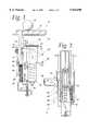
- FIG. 1is a side view of a drop target for a pinball game in a lowered position according to one embodiment of the present invention
- FIG. 2is a rear view of the drop target of FIG. 1 in the lowered position
- FIG. 3is a side view depicting the drop target of FIG. 1 in a raised position
- FIG. 4is a rear view of the drop target of FIG. 1 in the raised position.
- FIG. 5is a block diagram illustrating operation of a game controller with the drop target of FIG. 1.
- a mounting bracket 18secures the drop target 10 to the underside of the playfield 14 and maintains the drop target 10 in an orientation generally perpendicular to the playfield 14.
- the playfieldis at a slight angle to horizontal, such that the target deviates slightly from vertical.
- Secondary brackets 20, 21are provided for attaching a solenoid 22 to the mounting bracket 18.
- the solenoid 22includes a coil 24, plunger 26 and electrical contacts 28--28 (one of which is obscured by the other in FIGS. 1 and 3) through which an energizing signal may be applied.
- the plunger 26is initially biased toward a lowermost vertical position (FIG. 1), in which its distal end 30 projects a distance of about four centimeters below the coil 24.
- a magnetic fieldis generated which drives the plunger 26 into the coil until it reaches an uppermost vertical position (FIG. 3) in which the distal end 30 of the plunger 26 projects only about one centimeter below the coil.
- the coil 24consists of 1500 turns of 26 gauge copper wire. It will be appreciated however, that alternative sizes and/or types of coils may be used. Coils having fewer or greater numbers of turns and/or using different gauge wire may be used, for example, to meet space and power constraints. Similarly, alternative sizes and/or types of plungers may be used, for example,to alter the upper and lower positions and/or to alter the range of motion of the plunger 26 as needed or desired. Target drivers other than solenoids may also be used.
- the plunger 26is connected at its distal end 30 to an actuator bracket 32.
- the actuator bracket 32includes identical, opposed left and right arms 34--34 (one of which is obscured by the other in FIGS. 1 and 3) extending around the sides of the mounting bracket 18 and projecting toward the target element 12.
- the arms 34--34are angled inwardly toward each other at their distal ends, on the opposite side of mounting bracket 18, to define a catch device 36--36 adapted to engage with a cooperating latching surface 38 of the target element 12..
- the actuator bracket 32(including arms 34--34 and catch device 36--36) moves relative to the mounting bracket 18 in response to movement of the plunger 26. In FIG.
- the latching surface 38comprises a grooved depression 40 and a projecting upper lip 42.
- the catch device 36projects into the depression 40 and is engaged by the lip 42.
- Retaining spring 44provides lateral force to keep the catch device 36 engaged with the latching surface 38 during controlled movement of the target element 12.
- a biasing tension spring 46is affixed to the bracket 18 and target 12 by respective notches 48,50.
- the spring 46When the target 12 is in its lowered position (FIGS. 1 and 2), the spring 46 is relaxed.
- the target 12is in its upper position (FIGS. 3 and 4), the spring is extended and tensioned so as to bias the target 12 toward its lowered position. In the absence of any external force, therefore, the spring 46 maintains the target 12 in its lowered position. Movement of the target 12 from its lowered position to its raised position is achieved upon energization of the solenoid 22 and the engagement of the latching surface 38 of the target with the catch device 36 of the actuator bracket 32.
- Energization of the solenoid 22causes the coil 24 to carry an electric current, which in turn generates a magnetic flux drawing the plunger 26 into the coil 24.
- Upward movement of the plunger 26(for projecting the target into the playfield in the orientation shown in FIGS. 1-4), is achieved when the magnetic flux draws the plunger 26 upward with a force sufficient to overcome gravity and the bias of the spring 46.
- An adjustable stop bracket 52extends horizontally from a lower portion of the mounting bracket 18. When the drop target 10 is in its lowered position (FIG. 1), the stop bracket 52 thereby "stops" the drop target 10 at a height determined by the position of the stop bracket 52.
- the position of the stop bracket 52is adjustable by means of an adjusting screw 56 to vary the relative height of the drop target 10 in its retracted position. Adjustment of the stop bracket 52 may be required, for example, to compensate for varying thicknesses of playfields and to ensure that the top surface of the drop target 10, when retracted, is below the top surface of the playfield.
- the initial energizing pulseis an ac voltage pulse having a magnitude of fifty volts and a duration of 32 milliseconds. It will be appreciated, however, that the initial pulse may comprise any electrical signal operable to produce a magnetic flux which draws the plunger 26 into the solenoid 22 with enough force to overcome gravity and the inertia of the spring 46.
- the initial pulsemay be other than an ac pulse, may have a magnitude greater than or less than fifty volts and/or may have a longer or shorter duration than 32 milliseconds.
- the plunger 26moves upward into the coil to its uppermost position and the target 12 is moved into its raised position (FIG. 3). Thereafter, the plunger 26 and target 12 are maintained in their respective uppermost and raised positions by applying a successive pattern of energizing pulses across the electrical contacts 28--28 of the solenoid 22.
- the successive patternmay comprise virtually any pattern of pulses which will produce a magnetic flux sufficient to hold the plunger 26 in its uppermost position.
- the energy required to hold the plunger 26 in its uppermost positionis generally less than the energy required to move the plunger 26 to its uppermost position. It has been determined according to principles of the present invention that the required energy to hold the plunger 26 in its uppermost position may provided by a pattern of voltage pulses, applied after the initial pulse.
- the voltage pulses in the patternmay have generally the same magnitude as the initial voltage pulse but are applied intermittently and thereby require less energy than the initial pulse.
- the provision of such a pattern of pulses, at a relatively low energy level,causes the solenoid 22 to dissipate less heat and thereby prolongs the life of the solenoid 22.
- the pattern of pulses applied after the initial pulsemay be fixed or, in one embodiment, may be variable during play of the pinball game according to instructions from a game controller 58 (FIG. 5).
- the number of pulse(s) within the framemay be fixed or varied during play of the pinball game according to instructions from the game controller.
- the game controllermay designate a selected number of one to sixteen pulses to be applied during each frame.
- the relative "placement" of the pulse(s) in the framee.g., the particular time window(s) to which the pulse(s) will coincide
- the game programmay cause the pulse to coincide with the first window of each frame.
- the game programmay cause the pulses to coincide with the first, sixth and twelfth windows of the frame.
- the repetitive pattern of pulsesdetermines the amount of energy that will be delivered to the solenoid 22 and the strength of "hold" of the plunger 26.
- the energy delivered to the solenoid 22is largely a function of the duty cycle of the pattern (defined by the number of pulses in the frame divided by the number of available time windows in the frame).
- the relative position of the pulses in the frameis largely irrelevant inasmuch as it does not affect the duty cycle of the pattern.
- the target 12can be dropped in the usual manner when a player strikes the target with a pinball 16, provided the pinball 16 has sufficient speed and momentum to cause the latching surface 42 to become disengaged from the catch device 36. When so disengaged, the target 12 is pulled to its lowered position by the spring 46. Additionally, a controlled drop may be executed without disengaging the latching surface 42 from the catch device 36, by the game controller 58 terminating the successive pulses or otherwise by providing pulses at an energy level insufficient to hold the plunger 26 in its uppermost position. Upon execution of the controlled drop, the plunger 26 and target 12 are moved to their lowermost positions, whereupon they may be raised again upon energization of the solenoid 22 in the manner heretofore described.
- a switch 60consisting of a body 61 and projecting actuator button 62, is provided for indicating the position of the target 12 to the game controller 58.
- An elongated rocker arm 64is pivotally connected at one end to the switch body 61. The other end of the rocker arm 64 forms a triangular projection 66.
- the triangular projection 66is engaged by a projecting indexing tab 68 of the drop target 10, causing the rocker arm 64 to depress the actuator button 62 and signal the game controller 58 that the target 12 is in the lower position.
- the target 12is in its upper position (FIG.
- the tab 68is moved away from engagement with the rocker arm projection 66, releasing the pressure on the actuator button 62 (thereby allowing the actuator button 62 to return to its undepressed state) and causing the rocker arm projection 66 to move back into the path of the indexing tab 68.
- the corresponding signals from the switch 60indicates to the game controller 58 whether the target 12 is in the raised or lowered position.
- the switchmay be normally open or normally closed and wired for positive or negative logic in their regard, to cooperate with the logic scheme of the controller.
- the game controller 58may be programmed via control software to vary the characteristics (e.g., magnitude, duration, or pattern) of the initial energizing pulse or successive pattern of energizing pulses.
- a device other than a solenoidmay be provided to drive the target between its upper and lower positions in response to signals from the game controller 58.
- the game controller 58monitors both the position of the target 12 and the status of the solenoid to determine whether the target was knocked down by a skilled shot or by a controlled drop. In the former case, the game controller will typically activate electrical switching to advance the player's score. The game controller 58 may also verify successful execution of a controlled drop or rise of the target 12. More particularly, the game controller 58 will determine that either of the following four conditions exist:
- condition (1)the game controller 58 verifies that a successful rise or resetting of the target 12 has occurred. If condition (2) occurs during play of the game, the game controller 58 determines that the target 12 has been dropped by a skilled shot, registers a score on the pinball machine as appropriate, and de-energizes the solenoid to re-engage the target latching surface 38 with the catch 36 of the actuator bracket 32. Condition (2) may also occur in a test mode in which, for example, a technician may evaluate operation of the device in response to different levels and/or patterns of engergizing pulses.
- condition (2)may indicate to the technician that the solenoid 22 has been energized with insufficient power to overcome the bias of the spring 46, or perhaps that some malfunction exists (such as a broken switch 60, loose connection, etc.) that would cause power otherwise sufficient to overcome the bias of the spring 46 not to be delivered to the solenoid 22. Thereafter, the technician may adjust the pattern and/or level of energizing pulses, repair or replace electrical components as appropriate.
- Condition (3)generally will not occur under normal circumstances and its occurrence would thereby indicate to the game controller 58 or technician that some other malfunction exists.
- condition (3)may indicate that the target 12 is actually down but, due perhaps to failure of the switch 60 or failure of the rocker arm 64 to properly depress the actuator button 62, the target 12 is erroneously indicated to be up.
- condition (4)occurs, the game controller 58 verifies that a successful controlled drop of the target 12 has occurred.
Landscapes
- Engineering & Computer Science (AREA)
- Multimedia (AREA)
- Pinball Game Machines (AREA)
Abstract
Description
Claims (27)
Priority Applications (2)
| Application Number | Priority Date | Filing Date | Title |
|---|---|---|---|
| US09/039,638US5924690A (en) | 1998-03-16 | 1998-03-16 | Drop target for a pinball game |
| DE19839799ADE19839799A1 (en) | 1998-03-16 | 1998-09-01 | Retractable goal for a pinball or pinball game |
Applications Claiming Priority (1)
| Application Number | Priority Date | Filing Date | Title |
|---|---|---|---|
| US09/039,638US5924690A (en) | 1998-03-16 | 1998-03-16 | Drop target for a pinball game |
Publications (1)
| Publication Number | Publication Date |
|---|---|
| US5924690Atrue US5924690A (en) | 1999-07-20 |
Family
ID=21906564
Family Applications (1)
| Application Number | Title | Priority Date | Filing Date |
|---|---|---|---|
| US09/039,638Expired - Fee RelatedUS5924690A (en) | 1998-03-16 | 1998-03-16 | Drop target for a pinball game |
Country Status (2)
| Country | Link |
|---|---|
| US (1) | US5924690A (en) |
| DE (1) | DE19839799A1 (en) |
Cited By (72)
| Publication number | Priority date | Publication date | Assignee | Title |
|---|---|---|---|---|
| US20040072625A1 (en)* | 2002-10-15 | 2004-04-15 | Fertig John K. | Golf game and method of game play using same |
| US20060292533A1 (en)* | 2005-06-22 | 2006-12-28 | Selod Omar F | System and method for gait training |
| USD678955S1 (en) | 2011-09-26 | 2013-03-26 | Wms Gaming Inc. | Gaming machine |
| USD678956S1 (en) | 2011-09-26 | 2013-03-26 | Wms Gaming Inc. | Gaming machine |
| USD678958S1 (en) | 2011-09-26 | 2013-03-26 | Wms Gaming Inc. | Gaming machine |
| USD678957S1 (en) | 2011-09-26 | 2013-03-26 | Wms Gaming Inc. | Gaming machine |
| USD681130S1 (en) | 2011-09-26 | 2013-04-30 | Wms Gaming Inc. | Gaming machine |
| USD682948S1 (en) | 2011-09-26 | 2013-05-21 | Wms Gaming Inc. | Gaming machine |
| USD691665S1 (en) | 2012-09-26 | 2013-10-15 | Wms Gaming Inc. | Gaming machine |
| USD691666S1 (en) | 2011-09-26 | 2013-10-15 | Wms Gaming Inc. | Gaming machine |
| USD704273S1 (en) | 2012-09-26 | 2014-05-06 | Wms Gaming Inc. | Gaming machine |
| USD712975S1 (en) | 2013-04-17 | 2014-09-09 | Wms Gaming Inc. | Gaming machine |
| USD730993S1 (en) | 2013-09-20 | 2015-06-02 | Wms Gaming Inc. | Inclined input interface for a gaming terminal |
| USD771193S1 (en) | 2011-11-11 | 2016-11-08 | Bally Gaming, Inc. | Game display screen with multiple arrays of reels |
| USD812149S1 (en) | 2016-03-30 | 2018-03-06 | Bally Gaming, Inc. | Gaming machine with curved display |
| USD832358S1 (en) | 2016-09-13 | 2018-10-30 | Bally Gaming, Inc. | Gaming machine with curved display |
| USD832355S1 (en) | 2016-09-13 | 2018-10-30 | Bally Gaming, Inc. | Gaming machine with curved display |
| USD832356S1 (en) | 2016-09-13 | 2018-10-30 | Bally Gaming, Inc. | Gaming machine with curved display |
| USD832357S1 (en) | 2016-09-13 | 2018-10-30 | Bally Gaming, Inc. | Gaming machine with curved display |
| USD836164S1 (en) | 2016-09-13 | 2018-12-18 | Bally Gaming, Inc. | Curved display for a gaming machine |
| USD843464S1 (en) | 2016-09-13 | 2019-03-19 | Bally Gaming, Inc. | Gaming machine with curved display |
| USD843459S1 (en) | 2016-03-30 | 2019-03-19 | Bally Gaming, Inc. | Gaming machine with curved display |
| USD843474S1 (en) | 2013-04-17 | 2019-03-19 | Bally Gaming, Inc. | Gaming machine |
| USD843458S1 (en) | 2016-03-30 | 2019-03-19 | Bally Gaming, Inc. | Gaming machine with curved display |
| USD843463S1 (en) | 2016-09-13 | 2019-03-19 | Bally Gaming, Inc. | Gaming machine with curved display |
| USD843460S1 (en) | 2016-09-13 | 2019-03-19 | Bally Gaming, Inc. | Gaming machine with curved display |
| USD843480S1 (en) | 2018-06-01 | 2019-03-19 | Bally Gaming, Inc. | Gaming machine with curved display |
| USD843462S1 (en) | 2016-09-13 | 2019-03-19 | Bally Gaming, Inc. | Gaming machine with curved display |
| USD843461S1 (en) | 2016-09-13 | 2019-03-19 | Bally Gaming, Inc. | Gaming machine with curved display |
| USD843465S1 (en) | 2016-09-13 | 2019-03-19 | Bally Gaming, Inc. | Gaming machine with curved display |
| USD843466S1 (en) | 2016-09-13 | 2019-03-19 | Bally Gaming, Inc. | Gaming machine with curved display |
| USD871506S1 (en) | 2016-09-13 | 2019-12-31 | Bally Gaming, Inc. | Gaming machine with curved displays |
| USD872188S1 (en) | 2018-07-24 | 2020-01-07 | Bally Gaming, Inc. | Gaming machine |
| USD872189S1 (en) | 2018-07-24 | 2020-01-07 | Bally Gaming, Inc. | Gaming machine |
| USD873921S1 (en) | 2018-07-24 | 2020-01-28 | Bally Gaming, Inc. | Gaming machine |
| USD877811S1 (en) | 2018-07-02 | 2020-03-10 | Sg Gaming, Inc. | Gaming machine |
| USD878477S1 (en) | 2018-07-02 | 2020-03-17 | Sg Gaming, Inc. | Gaming machine |
| USD880614S1 (en) | 2018-07-24 | 2020-04-07 | Sg Gaming, Inc. | Gaming machine |
| USD880612S1 (en) | 2018-07-24 | 2020-04-07 | Sg Gaming, Inc. | Gaming machine |
| USD880613S1 (en) | 2018-07-24 | 2020-04-07 | Sg Gaming, Inc. | Gaming machine |
| USD880615S1 (en) | 2018-07-24 | 2020-04-07 | Sg Gaming, Inc. | Gaming machine |
| USD880609S1 (en) | 2018-07-24 | 2020-04-07 | Bally Gaming, Inc. | Gaming machine with graphical user interface |
| USD880611S1 (en) | 2018-07-24 | 2020-04-07 | Sg Gaming, Inc. | Gaming machine |
| USD880608S1 (en) | 2018-07-24 | 2020-04-07 | Sg Gaming, Inc. | Gaming machine |
| USD880610S1 (en) | 2018-07-24 | 2020-04-07 | Sg Gaming, Inc. | Gaming machine |
| USD880606S1 (en) | 2017-09-28 | 2020-04-07 | Sg Gaming, Inc. | Gaming terminal |
| USD881284S1 (en) | 2018-07-24 | 2020-04-14 | Sg Gaming, Inc. | Gaming machine |
| USD881285S1 (en) | 2018-07-24 | 2020-04-14 | Sg Gaming, Inc. | Gaming machine |
| USD881995S1 (en) | 2018-07-24 | 2020-04-21 | Sg Gaming, Inc. | Gaming machine |
| USD882695S1 (en) | 2018-07-24 | 2020-04-28 | Sg Gaming, Inc. | Gaming machine |
| USD882694S1 (en) | 2018-07-24 | 2020-04-28 | Sg Gaming, Inc. | Gaming machine |
| USD882700S1 (en) | 2017-04-14 | 2020-04-28 | Sg Gaming, Inc. | Gaming machine carousel display |
| USD882699S1 (en) | 2017-04-14 | 2020-04-28 | Sg Gaming, Inc. | Gaming machine carousel display |
| USD883393S1 (en) | 2017-04-14 | 2020-05-05 | Sg Gaming, Inc. | Gaming machine carousel display |
| USD884079S1 (en) | 2018-07-24 | 2020-05-12 | Sg Gaming, Inc. | Gaming machine |
| USD886905S1 (en) | 2018-07-24 | 2020-06-09 | Sg Gaming, Inc. | Gaming machine |
| USD887495S1 (en) | 2018-07-24 | 2020-06-16 | Sg Gaming, Inc. | Gaming machine |
| USD889553S1 (en) | 2017-09-28 | 2020-07-07 | Sg Gaming, Inc. | Gaming terminal |
| USD889552S1 (en) | 2017-09-28 | 2020-07-07 | Sg Gaming, Inc. | Gaming terminal |
| USD894285S1 (en) | 2018-07-24 | 2020-08-25 | Sg Gaming, Inc. | Gaming machine |
| USD896313S1 (en) | 2016-03-30 | 2020-09-15 | Sg Gaming, Inc. | Gaming machine with curved display |
| USD913376S1 (en) | 2018-07-02 | 2021-03-16 | Sg Gaming, Inc. | Gaming machine |
| USD913377S1 (en) | 2018-07-02 | 2021-03-16 | Sg Gaming, Inc. | Gaming machine |
| USD915523S1 (en) | 2017-09-28 | 2021-04-06 | Sg Gaming, Inc. | Gaming terminal |
| USD952752S1 (en) | 2019-10-11 | 2022-05-24 | Sg Gaming, Inc. | Gaming machine |
| USD952751S1 (en) | 2019-10-11 | 2022-05-24 | Sg Gaming, Inc. | Gaming machine |
| USD952750S1 (en) | 2019-10-11 | 2022-05-24 | Sg Gaming, Inc. | Gaming machine |
| USD952754S1 (en) | 2019-10-11 | 2022-05-24 | Sg Gaming, Inc. | Gaming machine |
| USD952755S1 (en) | 2019-10-11 | 2022-05-24 | Sg Gaming, Inc. | Gaming machine |
| USD952753S1 (en) | 2019-10-11 | 2022-05-24 | Sg Gaming, Inc. | Gaming machine |
| USD1034821S1 (en) | 2018-07-24 | 2024-07-09 | Lnw Gaming, Inc. | Gaming machine |
| USD1034820S1 (en) | 2018-07-24 | 2024-07-09 | Lnw Gaming, Inc. | Gaming machine |
Citations (29)
| Publication number | Priority date | Publication date | Assignee | Title |
|---|---|---|---|---|
| US3578802A (en)* | 1969-02-25 | 1971-05-18 | Williams Electronic Mfg Corp | Vertically adjustable bumper for ball rolling games |
| US3826883A (en)* | 1972-09-05 | 1974-07-30 | Bally Mfg Corp | Lock-out ball bumper switch |
| US3877701A (en)* | 1972-09-05 | 1975-04-15 | Bally Mfg Corp | Pin-ball surface game device having lock-out ball bumper |
| US4037842A (en)* | 1975-05-08 | 1977-07-26 | Marvin Glass & Associates | Target device for pinball games |
| US4097047A (en)* | 1975-12-24 | 1978-06-27 | Kabushiki Kaisha Sega Enterprises | Device for kicking ball in a pinball game machine |
| US4109916A (en)* | 1976-05-17 | 1978-08-29 | Marvin Glass & Associates | Pinball game with simultaneous projectors |
| US4190252A (en)* | 1978-01-18 | 1980-02-26 | Atari, Inc. | Multiple drop target assembly for amusement game |
| US4221384A (en)* | 1979-03-15 | 1980-09-09 | D. Gottlieb & Co. | Drop target assembly for pinball game |
| US4243222A (en)* | 1979-03-23 | 1981-01-06 | Bally Manufacturing Corporation | Seesaw targets apparatus for pinball game |
| US4249736A (en)* | 1979-07-02 | 1981-02-10 | Stern Electronics, Inc. | Drop target assembly for pinball game |
| US4257604A (en)* | 1979-06-04 | 1981-03-24 | Bally Manufacturing Corporation | In-line drop targets |
| US4260156A (en)* | 1980-01-10 | 1981-04-07 | Kabushiki Kaisha Universal | Target apparatus for pinball machines |
| US4353553A (en)* | 1981-02-17 | 1982-10-12 | D. Gottlieb & Co. | Drop target assembly for pinball game |
| US4354681A (en)* | 1981-02-17 | 1982-10-19 | D. Gottlieb & Co. | Drop target assembly for pinball game |
| US4426081A (en)* | 1982-08-25 | 1984-01-17 | Wico Corporation | Drop target apparatus |
| US4429876A (en)* | 1981-12-24 | 1984-02-07 | Bally Manufacturing Corporation | Pinball machine and play feature thereof |
| US4438929A (en)* | 1981-08-03 | 1984-03-27 | Wico Corporation | Drop target with cam means |
| US4460175A (en)* | 1979-03-15 | 1984-07-17 | Mylstar Electronics, Inc. | Drop target assembly for pinball game |
| US4487416A (en)* | 1982-08-19 | 1984-12-11 | Wico Corporation | Rotatable kicker for pinball game |
| US4508343A (en)* | 1982-10-22 | 1985-04-02 | Wico Corporation | Pinball game with randomly operable drop targets |
| US4773646A (en)* | 1987-01-28 | 1988-09-27 | Williams Electronics Games, Inc. | Moving target assembly |
| US4804186A (en)* | 1987-12-02 | 1989-02-14 | Premier Technology, Inc. | Pinball drop target assembly |
| US4822046A (en)* | 1987-02-25 | 1989-04-18 | Williams Electronics | Two and four position target assembly |
| US4892309A (en)* | 1987-02-25 | 1990-01-09 | Williams Electronics Games, Inc. | Two and four position target assembly |
| US4943061A (en)* | 1989-08-22 | 1990-07-24 | Williams Electronics Games, Inc. | Multi-position drop target |
| US4981298A (en)* | 1989-10-06 | 1991-01-01 | Williams Electronics Games, Inc. | Ball diverter playfield feature for pinball machines |
| US5123647A (en)* | 1991-04-26 | 1992-06-23 | Williams Electronics Games, Inc. | Interactive playfield feature for pinball games |
| US5516103A (en)* | 1995-07-21 | 1996-05-14 | Williams Electronics Games, Inc. | Dual function drop target for pinball game |
| US5529294A (en)* | 1995-01-18 | 1996-06-25 | Williams Electronics Games, Inc. | Lighted stand-up target |
- 1998
- 1998-03-16USUS09/039,638patent/US5924690A/ennot_activeExpired - Fee Related
- 1998-09-01DEDE19839799Apatent/DE19839799A1/ennot_activeWithdrawn
Patent Citations (29)
| Publication number | Priority date | Publication date | Assignee | Title |
|---|---|---|---|---|
| US3578802A (en)* | 1969-02-25 | 1971-05-18 | Williams Electronic Mfg Corp | Vertically adjustable bumper for ball rolling games |
| US3826883A (en)* | 1972-09-05 | 1974-07-30 | Bally Mfg Corp | Lock-out ball bumper switch |
| US3877701A (en)* | 1972-09-05 | 1975-04-15 | Bally Mfg Corp | Pin-ball surface game device having lock-out ball bumper |
| US4037842A (en)* | 1975-05-08 | 1977-07-26 | Marvin Glass & Associates | Target device for pinball games |
| US4097047A (en)* | 1975-12-24 | 1978-06-27 | Kabushiki Kaisha Sega Enterprises | Device for kicking ball in a pinball game machine |
| US4109916A (en)* | 1976-05-17 | 1978-08-29 | Marvin Glass & Associates | Pinball game with simultaneous projectors |
| US4190252A (en)* | 1978-01-18 | 1980-02-26 | Atari, Inc. | Multiple drop target assembly for amusement game |
| US4221384A (en)* | 1979-03-15 | 1980-09-09 | D. Gottlieb & Co. | Drop target assembly for pinball game |
| US4460175A (en)* | 1979-03-15 | 1984-07-17 | Mylstar Electronics, Inc. | Drop target assembly for pinball game |
| US4243222A (en)* | 1979-03-23 | 1981-01-06 | Bally Manufacturing Corporation | Seesaw targets apparatus for pinball game |
| US4257604A (en)* | 1979-06-04 | 1981-03-24 | Bally Manufacturing Corporation | In-line drop targets |
| US4249736A (en)* | 1979-07-02 | 1981-02-10 | Stern Electronics, Inc. | Drop target assembly for pinball game |
| US4260156A (en)* | 1980-01-10 | 1981-04-07 | Kabushiki Kaisha Universal | Target apparatus for pinball machines |
| US4353553A (en)* | 1981-02-17 | 1982-10-12 | D. Gottlieb & Co. | Drop target assembly for pinball game |
| US4354681A (en)* | 1981-02-17 | 1982-10-19 | D. Gottlieb & Co. | Drop target assembly for pinball game |
| US4438929A (en)* | 1981-08-03 | 1984-03-27 | Wico Corporation | Drop target with cam means |
| US4429876A (en)* | 1981-12-24 | 1984-02-07 | Bally Manufacturing Corporation | Pinball machine and play feature thereof |
| US4487416A (en)* | 1982-08-19 | 1984-12-11 | Wico Corporation | Rotatable kicker for pinball game |
| US4426081A (en)* | 1982-08-25 | 1984-01-17 | Wico Corporation | Drop target apparatus |
| US4508343A (en)* | 1982-10-22 | 1985-04-02 | Wico Corporation | Pinball game with randomly operable drop targets |
| US4773646A (en)* | 1987-01-28 | 1988-09-27 | Williams Electronics Games, Inc. | Moving target assembly |
| US4822046A (en)* | 1987-02-25 | 1989-04-18 | Williams Electronics | Two and four position target assembly |
| US4892309A (en)* | 1987-02-25 | 1990-01-09 | Williams Electronics Games, Inc. | Two and four position target assembly |
| US4804186A (en)* | 1987-12-02 | 1989-02-14 | Premier Technology, Inc. | Pinball drop target assembly |
| US4943061A (en)* | 1989-08-22 | 1990-07-24 | Williams Electronics Games, Inc. | Multi-position drop target |
| US4981298A (en)* | 1989-10-06 | 1991-01-01 | Williams Electronics Games, Inc. | Ball diverter playfield feature for pinball machines |
| US5123647A (en)* | 1991-04-26 | 1992-06-23 | Williams Electronics Games, Inc. | Interactive playfield feature for pinball games |
| US5529294A (en)* | 1995-01-18 | 1996-06-25 | Williams Electronics Games, Inc. | Lighted stand-up target |
| US5516103A (en)* | 1995-07-21 | 1996-05-14 | Williams Electronics Games, Inc. | Dual function drop target for pinball game |
Non-Patent Citations (8)
| Title |
|---|
| Description of Prior Art Photographs 1 6, 2 pgs., date Jul. 1998.* |
| Description of Prior Art Photographs 1-6, 2 pgs., date Jul. 1998. |
| Pinball Drop Target (Williams) Photograph 1: Side view, target raised (Jul. 1998).* |
| Pinball Drop Target (Williams) Photograph 2: Front view, target raised (Jul. 1998).* |
| Pinball Drop Target (Williams) Photograph 3: Back view, target raised (Jul. 1998).* |
| Pinball Drop Target (Williams) Photograph 4: Side view, target lowered (Jul. 1998).* |
| Pinball Drop Target (Williams) Photograph 5: Front view, target lowered (Jul. 1998).* |
| Pinball Drop Target (Williams) Photograph 6: Back view, target lowered (Jul. 1998).* |
Cited By (115)
| Publication number | Priority date | Publication date | Assignee | Title |
|---|---|---|---|---|
| US20040072625A1 (en)* | 2002-10-15 | 2004-04-15 | Fertig John K. | Golf game and method of game play using same |
| US20060292533A1 (en)* | 2005-06-22 | 2006-12-28 | Selod Omar F | System and method for gait training |
| USD681130S1 (en) | 2011-09-26 | 2013-04-30 | Wms Gaming Inc. | Gaming machine |
| USD678956S1 (en) | 2011-09-26 | 2013-03-26 | Wms Gaming Inc. | Gaming machine |
| USD678958S1 (en) | 2011-09-26 | 2013-03-26 | Wms Gaming Inc. | Gaming machine |
| USD678957S1 (en) | 2011-09-26 | 2013-03-26 | Wms Gaming Inc. | Gaming machine |
| USD682948S1 (en) | 2011-09-26 | 2013-05-21 | Wms Gaming Inc. | Gaming machine |
| USD691666S1 (en) | 2011-09-26 | 2013-10-15 | Wms Gaming Inc. | Gaming machine |
| USD704275S1 (en) | 2011-09-26 | 2014-05-06 | Wms Gaming Inc. | Gaming machine |
| USD678955S1 (en) | 2011-09-26 | 2013-03-26 | Wms Gaming Inc. | Gaming machine |
| USD771193S1 (en) | 2011-11-11 | 2016-11-08 | Bally Gaming, Inc. | Game display screen with multiple arrays of reels |
| USD783096S1 (en) | 2011-11-11 | 2017-04-04 | Bally Gaming, Inc. | Game display screen with multiple arrays of reels |
| USD691665S1 (en) | 2012-09-26 | 2013-10-15 | Wms Gaming Inc. | Gaming machine |
| USD704273S1 (en) | 2012-09-26 | 2014-05-06 | Wms Gaming Inc. | Gaming machine |
| USD843475S1 (en) | 2013-04-17 | 2019-03-19 | Bally Gaming, Inc. | Gaming machine |
| USD882698S1 (en) | 2013-04-17 | 2020-04-28 | Sg Gaming, Inc. | Gaming machine |
| USD742974S1 (en) | 2013-04-17 | 2015-11-10 | Bally Gaming, Inc. | Gaming machine |
| USD843476S1 (en) | 2013-04-17 | 2019-03-19 | Bally Gaming, Inc. | Gaming machine |
| USD895019S1 (en) | 2013-04-17 | 2020-09-01 | Sg Gaming, Inc. | Gaming machine |
| USD843477S1 (en) | 2013-04-17 | 2019-03-19 | Bally Gaming, Inc. | Gaming machine |
| USD712975S1 (en) | 2013-04-17 | 2014-09-09 | Wms Gaming Inc. | Gaming machine |
| USD844062S1 (en) | 2013-04-17 | 2019-03-26 | Bally Gaming, Inc. | Gaming machine |
| USD843478S1 (en) | 2013-04-17 | 2019-03-19 | Bally Gaming, Inc. | Gaming machine |
| USD882697S1 (en) | 2013-04-17 | 2020-04-28 | Sg Gaming, Inc. | Gaming machine |
| USD843474S1 (en) | 2013-04-17 | 2019-03-19 | Bally Gaming, Inc. | Gaming machine |
| USD882696S1 (en) | 2013-04-17 | 2020-04-28 | Sg Gaming, Inc. | Gaming machine |
| USD760846S1 (en) | 2013-09-20 | 2016-07-05 | Bally Gaming, Inc. | Inclined input interface for a gaming terminal |
| USD730993S1 (en) | 2013-09-20 | 2015-06-02 | Wms Gaming Inc. | Inclined input interface for a gaming terminal |
| USD812148S1 (en) | 2016-03-30 | 2018-03-06 | Bally Gaming, Inc. | Gaming machine with curved display |
| USD843458S1 (en) | 2016-03-30 | 2019-03-19 | Bally Gaming, Inc. | Gaming machine with curved display |
| USD843459S1 (en) | 2016-03-30 | 2019-03-19 | Bally Gaming, Inc. | Gaming machine with curved display |
| USD896315S1 (en) | 2016-03-30 | 2020-09-15 | Sg Gaming, Inc. | Gaming machine with curved display |
| USD896313S1 (en) | 2016-03-30 | 2020-09-15 | Sg Gaming, Inc. | Gaming machine with curved display |
| USD819747S1 (en) | 2016-03-30 | 2018-06-05 | Bally Gaming, Inc. | Gaming machine with curved display |
| USD896312S1 (en) | 2016-03-30 | 2020-09-15 | Sg Gaming, Inc. | Gaming machine with curved display |
| USD843479S1 (en) | 2016-03-30 | 2019-03-19 | Bally Gaming, Inc. | Gaming machine with curved display |
| USD896314S1 (en) | 2016-03-30 | 2020-09-15 | Sg Gaming, Inc. | Gaming machine with curved display |
| USD910116S1 (en) | 2016-03-30 | 2021-02-09 | Sg Gaming, Inc. | Gaming machine with curved display |
| USD812146S1 (en) | 2016-03-30 | 2018-03-06 | Bally Gaming, Inc. | Gaming machine with curved display |
| USD1055165S1 (en) | 2016-03-30 | 2024-12-24 | Lnw Gaming, Inc. | Gaming machine with curved display |
| USD812147S1 (en) | 2016-03-30 | 2018-03-06 | Bally Gaming, Inc. | Gaming machine with curved display |
| USD812149S1 (en) | 2016-03-30 | 2018-03-06 | Bally Gaming, Inc. | Gaming machine with curved display |
| USD843461S1 (en) | 2016-09-13 | 2019-03-19 | Bally Gaming, Inc. | Gaming machine with curved display |
| USD843466S1 (en) | 2016-09-13 | 2019-03-19 | Bally Gaming, Inc. | Gaming machine with curved display |
| USD843465S1 (en) | 2016-09-13 | 2019-03-19 | Bally Gaming, Inc. | Gaming machine with curved display |
| USD871506S1 (en) | 2016-09-13 | 2019-12-31 | Bally Gaming, Inc. | Gaming machine with curved displays |
| USD843462S1 (en) | 2016-09-13 | 2019-03-19 | Bally Gaming, Inc. | Gaming machine with curved display |
| USD843463S1 (en) | 2016-09-13 | 2019-03-19 | Bally Gaming, Inc. | Gaming machine with curved display |
| USD843460S1 (en) | 2016-09-13 | 2019-03-19 | Bally Gaming, Inc. | Gaming machine with curved display |
| USD843464S1 (en) | 2016-09-13 | 2019-03-19 | Bally Gaming, Inc. | Gaming machine with curved display |
| USD832358S1 (en) | 2016-09-13 | 2018-10-30 | Bally Gaming, Inc. | Gaming machine with curved display |
| USD832355S1 (en) | 2016-09-13 | 2018-10-30 | Bally Gaming, Inc. | Gaming machine with curved display |
| USD832356S1 (en) | 2016-09-13 | 2018-10-30 | Bally Gaming, Inc. | Gaming machine with curved display |
| USD832357S1 (en) | 2016-09-13 | 2018-10-30 | Bally Gaming, Inc. | Gaming machine with curved display |
| USD836164S1 (en) | 2016-09-13 | 2018-12-18 | Bally Gaming, Inc. | Curved display for a gaming machine |
| USD883393S1 (en) | 2017-04-14 | 2020-05-05 | Sg Gaming, Inc. | Gaming machine carousel display |
| USD882700S1 (en) | 2017-04-14 | 2020-04-28 | Sg Gaming, Inc. | Gaming machine carousel display |
| USD882699S1 (en) | 2017-04-14 | 2020-04-28 | Sg Gaming, Inc. | Gaming machine carousel display |
| USD1031854S1 (en) | 2017-09-28 | 2024-06-18 | Lnw Gaming, Inc. | Gaming terminal |
| USD880606S1 (en) | 2017-09-28 | 2020-04-07 | Sg Gaming, Inc. | Gaming terminal |
| USD915523S1 (en) | 2017-09-28 | 2021-04-06 | Sg Gaming, Inc. | Gaming terminal |
| USD1002738S1 (en) | 2017-09-28 | 2023-10-24 | Lnw Gaming, Inc. | Gaming terminal |
| USD889552S1 (en) | 2017-09-28 | 2020-07-07 | Sg Gaming, Inc. | Gaming terminal |
| USD1031852S1 (en) | 2017-09-28 | 2024-06-18 | Lnw Gaming, Inc. | Gaming terminal |
| USD1031853S1 (en) | 2017-09-28 | 2024-06-18 | Lnw Gaming, Inc. | Gaming terminal |
| USD1031855S1 (en) | 2017-09-28 | 2024-06-18 | Lnw Gaming, Inc. | Gaming terminal |
| USD889553S1 (en) | 2017-09-28 | 2020-07-07 | Sg Gaming, Inc. | Gaming terminal |
| USD1032728S1 (en) | 2017-09-28 | 2024-06-25 | Lnw Gaming, Inc. | Gaming terminal |
| USD1036553S1 (en) | 2017-09-28 | 2024-07-23 | Lnw Gaming, Inc. | Gaming terminal |
| USD843480S1 (en) | 2018-06-01 | 2019-03-19 | Bally Gaming, Inc. | Gaming machine with curved display |
| USD913376S1 (en) | 2018-07-02 | 2021-03-16 | Sg Gaming, Inc. | Gaming machine |
| USD913377S1 (en) | 2018-07-02 | 2021-03-16 | Sg Gaming, Inc. | Gaming machine |
| USD877811S1 (en) | 2018-07-02 | 2020-03-10 | Sg Gaming, Inc. | Gaming machine |
| USD878477S1 (en) | 2018-07-02 | 2020-03-17 | Sg Gaming, Inc. | Gaming machine |
| USD880611S1 (en) | 2018-07-24 | 2020-04-07 | Sg Gaming, Inc. | Gaming machine |
| USD1012186S1 (en) | 2018-07-24 | 2024-01-23 | Lnw Gaming, Inc. | Gaming machine with graphical user interface |
| USD894285S1 (en) | 2018-07-24 | 2020-08-25 | Sg Gaming, Inc. | Gaming machine |
| USD881995S1 (en) | 2018-07-24 | 2020-04-21 | Sg Gaming, Inc. | Gaming machine |
| USD881285S1 (en) | 2018-07-24 | 2020-04-14 | Sg Gaming, Inc. | Gaming machine |
| USD881284S1 (en) | 2018-07-24 | 2020-04-14 | Sg Gaming, Inc. | Gaming machine |
| USD880610S1 (en) | 2018-07-24 | 2020-04-07 | Sg Gaming, Inc. | Gaming machine |
| USD880608S1 (en) | 2018-07-24 | 2020-04-07 | Sg Gaming, Inc. | Gaming machine |
| USD884079S1 (en) | 2018-07-24 | 2020-05-12 | Sg Gaming, Inc. | Gaming machine |
| USD880609S1 (en) | 2018-07-24 | 2020-04-07 | Bally Gaming, Inc. | Gaming machine with graphical user interface |
| USD882694S1 (en) | 2018-07-24 | 2020-04-28 | Sg Gaming, Inc. | Gaming machine |
| USD880615S1 (en) | 2018-07-24 | 2020-04-07 | Sg Gaming, Inc. | Gaming machine |
| USD1069922S1 (en) | 2018-07-24 | 2025-04-08 | Lnw Gaming, Inc. | Gaming machine |
| USD1068941S1 (en) | 2018-07-24 | 2025-04-01 | Lnw Gaming, Inc. | Gaming machine with graphical user interface |
| USD872188S1 (en) | 2018-07-24 | 2020-01-07 | Bally Gaming, Inc. | Gaming machine |
| USD872189S1 (en) | 2018-07-24 | 2020-01-07 | Bally Gaming, Inc. | Gaming machine |
| USD1034820S1 (en) | 2018-07-24 | 2024-07-09 | Lnw Gaming, Inc. | Gaming machine |
| USD1034821S1 (en) | 2018-07-24 | 2024-07-09 | Lnw Gaming, Inc. | Gaming machine |
| USD880613S1 (en) | 2018-07-24 | 2020-04-07 | Sg Gaming, Inc. | Gaming machine |
| USD1011431S1 (en) | 2018-07-24 | 2024-01-16 | Lnw Gaming, Inc. | Gaming machine |
| USD882695S1 (en) | 2018-07-24 | 2020-04-28 | Sg Gaming, Inc. | Gaming machine |
| USD1012183S1 (en) | 2018-07-24 | 2024-01-23 | Lnw Gaming, Inc. | Gaming machine |
| USD1011430S1 (en) | 2018-07-24 | 2024-01-16 | Lnw Gaming, Inc. | Gaming machine |
| USD1012184S1 (en) | 2018-07-24 | 2024-01-23 | Lnw Gaming, Inc. | Gaming machine with graphical user interface |
| USD1012185S1 (en) | 2018-07-24 | 2024-01-23 | Lnw Gaming, Inc. | Gaming machine |
| USD1013044S1 (en) | 2018-07-24 | 2024-01-30 | Lnw Gaming, Inc. | Gaming machine |
| USD1018677S1 (en) | 2018-07-24 | 2024-03-19 | Lnw Gaming, Inc. | Gaming machine |
| USD1018678S1 (en) | 2018-07-24 | 2024-03-19 | Lnw Gaming, Inc. | Gaming machine |
| USD880612S1 (en) | 2018-07-24 | 2020-04-07 | Sg Gaming, Inc. | Gaming machine |
| USD880614S1 (en) | 2018-07-24 | 2020-04-07 | Sg Gaming, Inc. | Gaming machine |
| USD887495S1 (en) | 2018-07-24 | 2020-06-16 | Sg Gaming, Inc. | Gaming machine |
| USD886905S1 (en) | 2018-07-24 | 2020-06-09 | Sg Gaming, Inc. | Gaming machine |
| USD873921S1 (en) | 2018-07-24 | 2020-01-28 | Bally Gaming, Inc. | Gaming machine |
| USD1032721S1 (en) | 2018-07-24 | 2024-06-25 | Lnw Gaming, Inc. | Gaming machine with graphical user interface |
| USD1033542S1 (en) | 2018-07-24 | 2024-07-02 | Lnw Gaming, Inc. | Gaming machine |
| USD952753S1 (en) | 2019-10-11 | 2022-05-24 | Sg Gaming, Inc. | Gaming machine |
| USD952755S1 (en) | 2019-10-11 | 2022-05-24 | Sg Gaming, Inc. | Gaming machine |
| USD952754S1 (en) | 2019-10-11 | 2022-05-24 | Sg Gaming, Inc. | Gaming machine |
| USD952750S1 (en) | 2019-10-11 | 2022-05-24 | Sg Gaming, Inc. | Gaming machine |
| USD952751S1 (en) | 2019-10-11 | 2022-05-24 | Sg Gaming, Inc. | Gaming machine |
| USD952752S1 (en) | 2019-10-11 | 2022-05-24 | Sg Gaming, Inc. | Gaming machine |
Also Published As
| Publication number | Publication date |
|---|---|
| DE19839799A1 (en) | 1999-09-23 |
Similar Documents
| Publication | Publication Date | Title |
|---|---|---|
| US5924690A (en) | Drop target for a pinball game | |
| EP0510841B1 (en) | Interactive playfield feature for pinball games | |
| JP7215531B2 (en) | game machine | |
| US4373725A (en) | Pinball machine having magnetic ball control | |
| US4257604A (en) | In-line drop targets | |
| JP7230961B2 (en) | game machine | |
| JP3956397B2 (en) | Pachinko machine launcher | |
| CA1126773A (en) | Drop target assembly for pinball game | |
| US4424970A (en) | Panic post for pinball games | |
| EP0414348B1 (en) | Multi-position drop target | |
| US2184866A (en) | Game apparatus | |
| JPH06233858A (en) | Pachinko machine | |
| JP4561968B2 (en) | Game machine | |
| JP5547955B2 (en) | Game machine | |
| JP6687087B2 (en) | Amusement machine | |
| JP7755339B1 (en) | crane game device | |
| JP3023807B2 (en) | Ball game machine | |
| JP2002052192A (en) | Pachinko machine | |
| US2574721A (en) | Magnetic ball activator | |
| JP2002126202A (en) | Shooting device for game machine | |
| JP3038562B2 (en) | Ball launching device for ball games | |
| JP7106499B2 (en) | game machine | |
| JPH0669504B2 (en) | Pachinko machine | |
| JP2518345Y2 (en) | Variable winning device for pachinko machines | |
| JP4921059B2 (en) | Bullet ball machine |
Legal Events
| Date | Code | Title | Description |
|---|---|---|---|
| AS | Assignment | Owner name:WILLIAMS ELECTRONIC GAMES, INC., ILLINOIS Free format text:ASSIGNMENT OF ASSIGNORS INTEREST;ASSIGNORS:KOPERA, THOMAS M.;CORIALE, MATTHEW C.;REEL/FRAME:009048/0414 Effective date:19980311 | |
| AS | Assignment | Owner name:WILLIAMS ELECTRONICS GAMES, INC., ILLINOIS Free format text:CORRECTIVE ASSIGNMENT TO CORRECT THE ASSIGNEE, PREVIOUSLY RECORDED AT REEL 9048, FRAME 0414;ASSIGNORS:KOPERA, THOMAS M.;CORIALE, MATTHEW C.;REEL/FRAME:009400/0347 Effective date:19980311 | |
| FPAY | Fee payment | Year of fee payment:4 | |
| AS | Assignment | Owner name:ILLINOIS PINBALL COMPANY, ILLINOIS Free format text:ASSIGNMENT OF ASSIGNORS INTEREST;ASSIGNOR:WILLIAMS ELECTRONICS GAMES, INC.;REEL/FRAME:014560/0508 Effective date:20030915 | |
| FEPP | Fee payment procedure | Free format text:PAYOR NUMBER ASSIGNED (ORIGINAL EVENT CODE: ASPN); ENTITY STATUS OF PATENT OWNER: LARGE ENTITY | |
| REMI | Maintenance fee reminder mailed | ||
| LAPS | Lapse for failure to pay maintenance fees | ||
| STCH | Information on status: patent discontinuation | Free format text:PATENT EXPIRED DUE TO NONPAYMENT OF MAINTENANCE FEES UNDER 37 CFR 1.362 | |
| FP | Lapsed due to failure to pay maintenance fee | Effective date:20070720 |