US5924334A - Device for moving cam relative to its driving shaft - Google Patents
Device for moving cam relative to its driving shaftDownload PDFInfo
- Publication number
- US5924334A US5924334AUS08/905,962US90596297AUS5924334AUS 5924334 AUS5924334 AUS 5924334AUS 90596297 AUS90596297 AUS 90596297AUS 5924334 AUS5924334 AUS 5924334A
- Authority
- US
- United States
- Prior art keywords
- driving shaft
- cam
- shaft
- intermediate member
- link
- Prior art date
- Legal status (The legal status is an assumption and is not a legal conclusion. Google has not performed a legal analysis and makes no representation as to the accuracy of the status listed.)
- Expired - Fee Related
Links
Images


Classifications
- F—MECHANICAL ENGINEERING; LIGHTING; HEATING; WEAPONS; BLASTING
- F01—MACHINES OR ENGINES IN GENERAL; ENGINE PLANTS IN GENERAL; STEAM ENGINES
- F01L—CYCLICALLY OPERATING VALVES FOR MACHINES OR ENGINES
- F01L13/00—Modifications of valve-gear to facilitate reversing, braking, starting, changing compression ratio, or other specific operations
- F01L13/0015—Modifications of valve-gear to facilitate reversing, braking, starting, changing compression ratio, or other specific operations for optimising engine performances by modifying valve lift according to various working parameters, e.g. rotational speed, load, torque
- F01L13/0021—Modifications of valve-gear to facilitate reversing, braking, starting, changing compression ratio, or other specific operations for optimising engine performances by modifying valve lift according to various working parameters, e.g. rotational speed, load, torque by modification of rocker arm ratio
- F01L13/0026—Modifications of valve-gear to facilitate reversing, braking, starting, changing compression ratio, or other specific operations for optimising engine performances by modifying valve lift according to various working parameters, e.g. rotational speed, load, torque by modification of rocker arm ratio by means of an eccentric
- Y—GENERAL TAGGING OF NEW TECHNOLOGICAL DEVELOPMENTS; GENERAL TAGGING OF CROSS-SECTIONAL TECHNOLOGIES SPANNING OVER SEVERAL SECTIONS OF THE IPC; TECHNICAL SUBJECTS COVERED BY FORMER USPC CROSS-REFERENCE ART COLLECTIONS [XRACs] AND DIGESTS
- Y10—TECHNICAL SUBJECTS COVERED BY FORMER USPC
- Y10T—TECHNICAL SUBJECTS COVERED BY FORMER US CLASSIFICATION
- Y10T74/00—Machine element or mechanism
- Y10T74/21—Elements
- Y10T74/2101—Cams
- Y10T74/2102—Adjustable
Definitions
- the present inventionrelates to a device for moving a cam relative to its driving shaft.
- the inventioncan be used for a camshaft of an internal combustion engine for varying duration of opening of an intake or exhaust valve or phase of opening and closing of the valve in a dual overhead camshaft internal combustion engine.
- U.S. Pat. No. 5,365,896discloses a device for moving a hollow cam relative to its driving shaft that is driven by a crankshaft of an engine for rotation about a shaft axis.
- the deviceincludes a drive member connected to the driving shaft, a driven member connected to the hollow cam and an intermediate member operatively connected between the drive and driven members.
- a supporthas mounted therein the intermediate member.
- the intermediate memberhas an axis and a central hole that is wide enough to allow limited movement of the support to vary eccentricity of the axis thereof with respect to the shaft axis.
- the drive memberis coupled with the intermediate member by a first coupling at a first position spaced from the shaft axis.
- the driven memberis coupled with the intermediate member by a second coupling at a second position that is spaced in angular direction with respect to the shaft axis.
- Each of the first and second couplingshas a movable connection with the intermediate member to permit variation in its distance from the axis of the intermediate member during operation.
- the supportis pivoted via a pivot shaft to a framing structure for movement within a plane perpendicular to the shaft axis.
- the framing structureis fixedly mounted to a cylinder head of the associated engine.
- an actuatorrotates via a control rod an eccentric cam that is received in a hole of the support. Both the actuator and control rod are also mounted to the framing structure.
- the pivot shaftis needed for the support, thus increasing the number of component parts and requiring increased installation space.
- the reactionis transmitted via the first and second couplings to the intermediate member and then to the support.
- the supportmust bear stress due to the valve spring.
- the supportbends at a portion between the two spaced points, causing undesired deviation of the axis of the intermediate member from the shaft axis, causing a deviation from desired valve timing.
- An object of the present inventionis to improve the device of the above kind such that the support for the intermediate member is not employed.
- a device for moving a cam relative to a driving shaftcomprising:
- a driving shafthaving a shaft axis
- said intermediate memberhaving a central bore through which said driving shaft extends;
- cam ringdisposed within said central bore between said driving shaft and said intermediate member, said cam ring supporting said intermediate member.
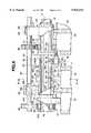
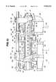
- FIG. 1is a fragmentary view, partly broken away, of a first embodiment of a device according to the present invention
- FIG. 2is a section taken through the line 2--2 in FIG. 1;
- FIG. 3is a top plan view of the device
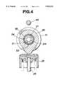
- FIG. 4is a section taken through the line 4--4 in FIG. 1;
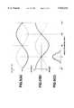
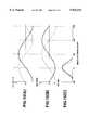
- FIG. 5(A)is a graph illustrating the variation of the angular speed of a hollow cam relative to the angular speed of a driving shaft
- FIG. 5(B)is a graph illustrating the variation of the phase of the hollow cam
- FIG. 5(C)is a valve lift diagram
- FIG. 6is a similar view to FIG. 1, illustrating a second embodiment
- FIG. 7is a section taken through the line 7--7 in FIG. 6;
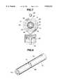
- FIG. 8is a perspective view of a driving shaft
- FIG. 9is a perspective view of a torque transmission member
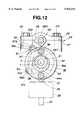
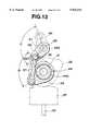
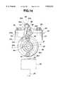
- FIG. 10is a similar view to FIG. 1, illustrating a third embodiment
- FIG. 11is a top plan view of the third embodiment
- FIG. 12is a section taken though the line 12--12 in FIG. 10;
- FIG. 13is a section taken though the line 13--13 in FIG. 10;
- FIG. 14is a section similar to FIG. 12;
- FIG. 15(A)is a graph illustrating the variation of the angular speed of a hollow cam relative to the angular speed of a driving shaft
- FIG. 15(B)is a graph illustrating the variation of the phase of the hollow cam.
- FIG. 15(C)is a valve lift diagram.
- the reference numeral 7indicates a portion of a cylinder head of a dual overhead cam internal combustion engine.
- the enginehas four cylinders arranged in line.
- four cylinder valvesare arranged. They can be divided into a first group of eight cylinder valves and a second group of eight cylinder valves.
- the cylinder valves belonging to the first groupare biased closed by valve springs, respectively, and are lifted by intake cams, respectively, against their valve springs to perform intake phase of the corresponding cylinders.
- the cylinder valves belonging to second groupare biased closed by valve springs, respectively, and are lifted by exhaust cams, respectively, against their valve springs to perform exhaust phase of the corresponding cylinders.
- the present inventionis applied to a phase changing mechanism incorporated in intake cam drive gear for intake valves 23 (see FIG. 2).
- the inventionmay be equally applicable to the exhaust valves.
- the intake valves 23have valve lifters 25, respectively.
- Each of the hollow cams 22has two axially spaced cam lobes 26 for cooperation with the two valve lifters 25 of the associated one of the cylinders.
- the hollow cams 22are supported by spaced cam bearings 24 that are secured to the cylinder head 7.
- Extending through a central tore 22a of each of the hollow cams 22is a driving shaft 21.
- the driving shaft 21is driven to rotate about a shaft axis X by conventional means such as a sprocket and a chain.
- Each of the cam bearings 24includes a main bracket cooperating with one of bearing surfaces formed on the cylinder head 7 and a sub bracket 28 on top of the main bracket 27.
- Two bolts 29 and 30extend through the sub bracket 28 and the man bracket 27.
- the main bracket 27has a bearing surface 27a recessed from the top thereof, while the sub bracket 28 has a bearing surface 28a recessed from the bottom thereof. These bearing surfaces 27a and 28a cooperate with each other to form a bearing supporting a control rod 46.
- the hollow cams 22are maintained in concentric relation with the driving shaft 21 for rotation about the shaft axis X.
- a plurality of, four in this embodiment, drive members 33are fixedly coupled with the driving shaft 21 and arranged to drive the hollow cams 22, respectively.
- drive members 33there are a plurality, four in this embodiment, driven members 31, which are integrally formed at axial end portions of the hollow cams 22, respectively.
- driven members 31which are integrally formed at axial end portions of the hollow cams 22, respectively.
- Each of the drive members 33mates with one of driven members 31.
- Disposed between the mated drive and driven members 33 and 31is an intermediate member 38.
- the drive member 33is in the form of a drive disc and includes an integral sleeve 33a fixedly coupled with the driving shaft 21 for unitary rotation by a cotter pin 34.
- the driven member 31is in the form of a driven disc integral with the one end of the corresponding hollow sleeve 22.
- the intermediate member 38is in the form of an annular disc that has a central hole 38a, through which the driving shaft 21 to pass.
- the central hole 38ais wide enough to allow insertion of a cam ring 44, in the form of an eccentric cam ring, within a space defined between the central hole 38a defining inner wall of the annular disc 38 and the outer surface of the driving shaft 21.
- This cam ring 44supports the annular disc 38 for rotation about an axis Y. Rotational movement of the cam ring 44 about the shaft axis X causes movement of the annular disc 38 in a plane perpendicular to the shaft axis X and alters direction of eccentricity of the axis Y with respect to the shaft axis X.
- the radial, with respect to the shaft axis X, dimension of the cam ring 44varies gradually in a direction of the circumference of an outer circle of the cam ring 44.
- the radial dimensiongradually decreases from the maximum to the minimum over 180 degrees angular displacement about the shaft axis X, and gradually increases from the minimum to the maximum over the next 180 degrees angular displacement about the shaft axis X.
- the reference numeral 44aindicates a maximum thickened portion at which the radial dimension is maximized.
- a first couplingcouples the drive member 33 with the intermediate 38 at a first position spaced from the shaft axis X.
- a second couplingcouples the driven member 31 with the intermediate member 38 at a second position spaced from the shaft axis X.
- the first and second positionsare displaced in an angular direction about the axis Y of the intermediate member 38. In this embodiment, the second position is displaced in the angular direction from the first position through 180 degrees.
- the first couplinghas a movable connection with the intermediate member 38 to permit variation in a distance of the first position.
- the first couplinghas a movable connection with the intermediate member 38 to permit variation in a distance of the first position from the shaft axis X.
- the second couplinghas a movable connection with the intermediate member 38 to permit variation in a distance of the second position from the shaft axis X.
- the first couplingincludes a first radial 35 formed in the face of the drive member 33 which is opposed to the intermediate member 38 and a first pin 37 received at one end in a pin receiving bore 40 of the intermediate member 38. At the opposite end portion, the first pin 37 engages in the first radial groove 35.
- the second couplingincludes a second radial groove 32 in the face of the driven member 31 which is opposed to the intermediate member 38 and a second pin 36 received at one end in a pin receiving bore 39 of the intermediate member 38. At the opposite end portion, the second pin 36 engages in the second radial groove 32.
- the first and second radial grooves 35 and 32end radially outwardly from the shaft axis X in the opposite direction
- the intermediate member 38rotates eccentrically with respect to the shaft axis X.
- the first pin 37moves along the radial groove 35 varying its distance from the shaft axis X
- the second pin 36moved along the radial groove 32 varying its distance from the shaft axis X.
- the first couplingcouples the drive member 33 with the intermediate member 38 at the first position where the first pin 37 is and has the movable connection defined by the first pin 37 and the radial groove 35.
- the second couplingcouples the driven member 31 with the intermediate member 38 at the second position where the second pin 36 is and has the movable connection defined by the second pin 36 and the radial groove 32.
- the cam ring 44has a first position where the thickened portion 44a assumes the lowest position with respect to the shaft axis X as illustrated in FIG. 2 and a second position where the thickened portion 44a assumes the highest position.
- a driver mechanism 43controls the angular position of each of the cam rings 44 via the corresponding one of transfer mechanisms 41.
- the transfer mechanism 41includes a torque transmission member 42 that is disposed between the outer surface of the driving shaft 21 and the inner surface of the hollow cam 22.
- the torque transmission member 42is connected at one end 42a to the cam ring 44.
- the sleeve 42fixedly carries a gear 45.
- the transfer mechanism 41also includes a gear 48 of a control rod or shaft 46. The gears 45 and 48 are intermeshed.
- the torque transmission member 42is in the form of a sleeve.
- the sleeve 42is integrated with the cam ring 44.
- the sleeve 42is press fitted into the central bore of the gear 45.
- the gear 45, sleeve 42 and cam ring 44can rotate as a unit.
- the gear 45is disposed between the sleeve 33a of the drive member 33 and the adjacent end of the hollow cam 22.
- the driver mechanism 43includes the control shaft 46 and an actuator, in the form of a stepping motor 47.
- the control shaft 46is supported at longitudinally spaced diametrically enlarged portions 46a by cam bearings 24.
- the mating bearing surfaces 27a and 28a of each of the cam bearings 24surround the corresponding one of the diametrically enlarged portions 46a.
- the above-mentioned gear 48is disposed and forms an integral part of the control shaft 46.
- the stepping motor 47is connected to a controller 49.
- the controller 49receives information from various sensors, such as a crankshaft angle sensor and an airflow meter, determines which angular position the cam ring 44 should take and outputs a control signal on which the stepping motor 47 operates.
- the driving shaft 21is formed with a supply passage 21a.
- the driving shaft 21is formed with first radial passages, only one being shown and indicated at 50.
- the first radial passages 50communicate at their inner ends with the supply passage 21a.
- the driving shaft 21is formed with second radial passages, only one being shown and indicated at 51.
- the second radial passages 51communicate at their inner ends with the supply passage 21a.
- the cam ring 44is formed with a radial passage 52 that communicates at its inner end with the outer end of the radial passage 50.
- the radial passage 52extends through the thickened portion 44a of the cam ring 44.
- the sleeve 42is formed with a radial port 53 that is opposed to the outer end of the radial passage 51.
- the radial port 53is smaller in diameter than the radial passage 51.
- the driving shaft 21is recessed from the outer surface thereof at spaced portions that are covered by the sleeves 42, respectively, to form first oil reservoirs, only one being and indicated at 54 in FIG. 1.
- Each of the first oil reservoirs 53establishes flow communication between the adjacent radial passage 51 and its mating radial opening 53.
- Each of the sleeves 42is recessed from the outer surface thereof at the portion that is covered by the associated hollow cam 22 to form a second oil reservoir 55.
- Each of the second oil reservoirs 55communicates with the corresponding radial opening 53.
- the second oil reservoir 55extends between the one and the opposite end portions 42a and 42b of the sleeve 42 in a direction along the shaft axis X. Besides, the second oil reservoir 55 extends continuously about the shaft axis X.
- the first oil reservoir 54extends continuously about the shaft axis X and has an axial extension along the shaft axis X shorter than the axial distance between which the one portion 42a and the opposite end portion 42b of the sleeve 42 are spaced.
- the provision of the first oil reservoir 54allows contact of the sleeve 42 with the outer surface of the driving shaft 21 at two axially spaced inner surfaces of the one and the opposite end portions 42a and 42b.
- the provision of the second oil reservoir 55allows contact of the sleeve 42 with the bore 22a defining inner surface of the hollow cam 22 at two axially spaced outer surfaces of the one and the opposite end portions 42a and 42b.
- the controller 49outputs a control signal to cause the stepping motor 47 to adjust the cam ring 44 to the first position as illustrated in FIG. 2.
- the thickened portion 44ais directed downwards, viewing in FIG. 2.
- the thickened portion 44ais the nearest the associated valve lifter 25, and the axis Y is displaced from the shaft axis X toward the associated valve lifter 25.
- the angular speed of the intermediate member 38is no longer equal to the angular speed ⁇ d of the driving shaft 21.
- FIG. 6(A)shows the variation of the angular speed ⁇ c of the hollow cam 22, and the dotted line shown in FIG. 6(B) the variation of the phase of the hollow cam 22.
- the hollow cam 22is retarded during the acceleration phase of the hollow cam 22, while it is advanced during the deceleration phase of the hollow cam 22.
- the top of each of the cam lobes 26is diametrically opposed, with respect to the shaft axis X, to the radial groove 32 of the driven member 31.
- the duration of opening of the valvebecomes the shortest at the angular position of the cam ring 44 as illustrated in FIG. 2.
- the dotted line in FIG. 5(C)illustrates the valve lift diagram under this condition.
- the controller 49Upon shift from low engine speed operation to high engine speed operation, the controller 49 instructs the stepping motor 47 to turn the control shaft 46 through predetermined angles, for example 180 degrees. This turns the gear 45 and sleeve 42 until the cam ring 44 turns 180 degrees from the position illustrated in FIG. 2 to the second position. In the second position, the thickened portion 44a is directed upwards, viewing in FIG. 2. In other words, the thickened portion 44a is the remotest from the associated valve lifter 25, and the axis Y is displaced from the shaft axis X away from the associated valve lifter 25.
- the fully drawn line shown in FIG. 5(A)illustrates the variation of the angular speed of the hollow cam 22.
- the fully drawn line shown in FIG. 5(A)illustrates the variation of the angular speed of the hollow cam 22.
- FIG. 5(B)illustrates the variation of the phase of the hollow cam 22. It is noted that the hollow cam 22 is advanced during the deceleration phase of the hollow cam 22, while it is retarded during the acceleration phase of the hollow cam 22.
- the fully drawn line shown in FIG. 5(C)shows the valve lift diagram. From this, it is appreciated that the duration of opening of the valve becomes the longest under this condition.
- the intermediate member 38is supported via the cam ring 44 on the driving shaft 21.
- the pivot shaft and its associated structurewhich are required in the prior art devices, are no longer needed.
- the driving shaft 21bears all of load imparted to the intermediate member 38 during operation.
- undesired displacement of the intermediate member 38which has been encountered in the prior art device, upon application of large load has been eliminated or at least greatly suppressed.
- the cam ring 44 and the intermediate member 38are sufficiently lubricated.
- the torque transmission sleeve 42 and the cam ring 44are sufficiently lubricated.
- Each of the hollow cams 22is supported by the cam bearings 24. Besides, it is supported via the torque transmission sleeve 42 by the driving shaft 21. Thus, undesired movement of the hollow cams 22 during operation is sufficiently suppressed.
- the hollow cam 22 and the torque transmission sleeve 42are supported at two axially spaced portions, respectively. Sticking of such components is prevented. It is no more necessary to hold required machining accuracy over the whole longitudinal length of them although such accuracy is required on each of the end portions or them.
- This second embodimentis substantially the same as the first embodiment except the constructions of first and second oil reservoirs of driving shaft and toque transmission sleeve, respectively.
- the first oil reservoirincludes two axial oil grooves 54, first one being communicating with a radial passage 51, the other or second one being spaced in an angular direction from the first one.
- the first oil reservoiralso includes a circumference groove 56 interconnecting the first and second axial grooves 54.
- the second oil reservoirincludes two axial grooves 55, first one being communicating with a radial port 53, the other or second one being spaced in an angular direction from the first one.
- the second oil reservoiralso includes a circumference groove 57 interconnecting the first and second axial grooves 55.
- This embodimentis substantially the same as the first embodiment except the employment of a link mechanism, instead of the gears 45 and 48, as each of transfer mechanisms 41.
- the link mechanismincludes a rain drop like first link 56 fixedly coupled at one end portion 56a with a torque transmission sleeve 42 at its end portion 42b.
- a rod like second link 57is pivoted at one end 57a to the opposite end portion 56b of the first link 56.
- a rain drop like third link 58is pivoted at one end portion 58a to the second link 57 at the opposite end portion 57b thereof.
- the third link 58is fixedly coupled with a control rod or shaft 46.
- the first link 56is enlarged in diameter at the one end portion 56a as compared to a small diameter at the opposite end portion 56b.
- the enlarged diameter one end portion 56ais formed with a bore receiving the opposite end portion 42b of the sleeve 42.
- a first support pin 59is fixedly connected to the opposite end portion 56b of the first link 56.
- the one end portion 57a of the second link 57is formed with a pin-receiving hole 57c that receives the first support pin 59. This connection allows pivotal relation between the second link 57 and the first link 56.
- the opposite end portion 57b of the second link 57is formed with a pin receiving hole 57d that receives a second support pin 60 fixed to the one end portion 58a of the third link 58.
- the third link 58is fixedly coupled with the control shaft 46. Pivotal relation between the second and third links 57 and 58 is established by the second support pin 60 within the pin-receiving hole 57d.
- the first and send links 56 and 58are generally parallel.
- the first link 56is adjusted to a downwardly angled first position as illustrated in FIG. 12.
- the first link 56is adjusted to an upwardly is angled second position as illustrated in FIG. 14.
- Turning the first link from the first position (FIG. 12) to the second position (FIG. 14)causes a cam ring 44 to turn clockwise, viewing in FIG. 12, through an angle ⁇ 2 of 90 degrees (see FIG. 13 also) to the second position shown in FIG. 14.
- the axis Y of an intermediate member 38is displaced laterally from the shaft axis X although in the first position the axis Y is displaced downwardly from the shaft axis.
- Turning the third link 58 via the control shaft 46 through an angle ⁇ 1causes the first link 56 to turn through the angle of ⁇ 2.
- the fully drawn line in FIG. 15(A)illustrates the variation of angle speed of a hollow cam 22 at high engine speeds when the link mechanism assume the second position as illustrated in FIG. 14.
- the fully drawn line in FIG. 15(B)illustrates the variation of the phase of the hollow cam 22 at high engine speed.
- the fully drawn line in FIG. 15(C)illustrates the valve lift diagram at high engine speeds.
- the dotted line in FIG. 15(A)illustrates the variation of the angle speed of the hollow cam 22 at low engine speeds when the link mechanism assume the first position as illustrated in FIG. 12.
- the dotted line in FIG. 15(B)illustrates the variation of the phase of the hollow cam 22 at low engine speed.
- the dotted line in FIG. 15(C)illustrates the valve lift diagram at low engine speeds.
Landscapes
- Engineering & Computer Science (AREA)
- Mechanical Engineering (AREA)
- General Engineering & Computer Science (AREA)
- Valve-Gear Or Valve Arrangements (AREA)
Abstract
Description
1. Field of the Invention
The present invention relates to a device for moving a cam relative to its driving shaft. The invention can be used for a camshaft of an internal combustion engine for varying duration of opening of an intake or exhaust valve or phase of opening and closing of the valve in a dual overhead camshaft internal combustion engine.
2. Description of the Related Art
U.S. Pat. No. 5,365,896 discloses a device for moving a hollow cam relative to its driving shaft that is driven by a crankshaft of an engine for rotation about a shaft axis. The device includes a drive member connected to the driving shaft, a driven member connected to the hollow cam and an intermediate member operatively connected between the drive and driven members. A support has mounted therein the intermediate member. The intermediate member has an axis and a central hole that is wide enough to allow limited movement of the support to vary eccentricity of the axis thereof with respect to the shaft axis. The drive member is coupled with the intermediate member by a first coupling at a first position spaced from the shaft axis. The driven member is coupled with the intermediate member by a second coupling at a second position that is spaced in angular direction with respect to the shaft axis. Each of the first and second couplings has a movable connection with the intermediate member to permit variation in its distance from the axis of the intermediate member during operation. The support is pivoted via a pivot shaft to a framing structure for movement within a plane perpendicular to the shaft axis. The framing structure is fixedly mounted to a cylinder head of the associated engine. To move the support, an actuator rotates via a control rod an eccentric cam that is received in a hole of the support. Both the actuator and control rod are also mounted to the framing structure.
According to the known device, the pivot shaft is needed for the support, thus increasing the number of component parts and requiring increased installation space.
In addition to a bearing structure for the hollow cam, another independent structure is required for supporting the pivot shaft, making it difficult to find installation space above the cylinder head.
The fact that the support is pivoted makes it difficult to adjust the intermediate member with respect to the shaft axis, causing a deviation from a desired valve timing control. This also causes cylinder to cylinder variation in valve timing, increasing probability of occurrence of irregular operation due to cylinder to cylinder variation in power output.
As the hollow cam opens the associated cylinder valve against its valve spring, the reaction is transmitted via the first and second couplings to the intermediate member and then to the support. At only two spaced points, the support must bear stress due to the valve spring. Thus, the support bends at a portion between the two spaced points, causing undesired deviation of the axis of the intermediate member from the shaft axis, causing a deviation from desired valve timing.
U.S. Pat. No. 5,333,579 discloses a known device similar to the device discussed above.
An object of the present invention is to improve the device of the above kind such that the support for the intermediate member is not employed.
According to the present invention, there is provided a device for moving a cam relative to a driving shaft, comprising:
a driving shaft having a shaft axis;
a hollow cam concentric with said driving shaft, said hollow cam having one end portion and opposite end portion;
a drive member fixed to said driving shaft;
a driven member fixed said hollow cam at said one end portion thereof;
an intermediate member having an axis and disposed between said drive and driven members;
a first coupling connecting said drive member with said intermediate member at a first position spaced from said shaft axis;
a second coupling connecting said driven member with said intermediate member at a second position spaced from said shaft axis and spaced in an angular direction, with respect to said shaft axis, from said first position;
said intermediate member having a central bore through which said driving shaft extends;
a cam ring disposed within said central bore between said driving shaft and said intermediate member, said cam ring supporting said intermediate member.
FIG. 1 is a fragmentary view, partly broken away, of a first embodiment of a device according to the present invention;
FIG. 2 is a section taken through theline 2--2 in FIG. 1;
FIG. 3 is a top plan view of the device;
FIG. 4 is a section taken through theline 4--4 in FIG. 1;
FIG. 5(A) is a graph illustrating the variation of the angular speed of a hollow cam relative to the angular speed of a driving shaft;
FIG. 5(B) is a graph illustrating the variation of the phase of the hollow cam;
FIG. 5(C) is a valve lift diagram;
FIG. 6 is a similar view to FIG. 1, illustrating a second embodiment;
FIG. 7 is a section taken through theline 7--7 in FIG. 6;
FIG. 8 is a perspective view of a driving shaft;
FIG. 9 is a perspective view of a torque transmission member;
FIG. 10 is a similar view to FIG. 1, illustrating a third embodiment;
FIG. 11 is a top plan view of the third embodiment;
FIG. 12 is a section taken though theline 12--12 in FIG. 10;
FIG. 13 is a section taken though theline 13--13 in FIG. 10;
FIG. 14 is a section similar to FIG. 12;
FIG. 15(A) is a graph illustrating the variation of the angular speed of a hollow cam relative to the angular speed of a driving shaft;
FIG. 15(B) is a graph illustrating the variation of the phase of the hollow cam; and
FIG. 15(C) is a valve lift diagram.
Referring to the accompanying drawings, like reference numerals and characters are used to throughout all of the Figures to denote like or similar parts or portions for the sake of simplicity of description.
In FIG. 1, thereference numeral 7 indicates a portion of a cylinder head of a dual overhead cam internal combustion engine. The engine has four cylinders arranged in line. For each of the four cylinders, four cylinder valves are arranged. They can be divided into a first group of eight cylinder valves and a second group of eight cylinder valves. The cylinder valves belonging to the first group are biased closed by valve springs, respectively, and are lifted by intake cams, respectively, against their valve springs to perform intake phase of the corresponding cylinders. The cylinder valves belonging to second group are biased closed by valve springs, respectively, and are lifted by exhaust cams, respectively, against their valve springs to perform exhaust phase of the corresponding cylinders.
In the first embodiment shown in FIG.1, the present invention is applied to a phase changing mechanism incorporated in intake cam drive gear for intake valves 23 (see FIG. 2). The invention may be equally applicable to the exhaust valves. Theintake valves 23 havevalve lifters 25, respectively. Instead of a single conventional intake camshaft, fourhollow cams 22, among which only two are shown in FIG. 1. Each of thehollow cams 22 has two axially spacedcam lobes 26 for cooperation with the twovalve lifters 25 of the associated one of the cylinders. Thehollow cams 22 are supported by spacedcam bearings 24 that are secured to thecylinder head 7. Extending through a central tore 22a of each of thehollow cams 22 is a drivingshaft 21. The drivingshaft 21 is driven to rotate about a shaft axis X by conventional means such as a sprocket and a chain.
Each of thecam bearings 24 includes a main bracket cooperating with one of bearing surfaces formed on thecylinder head 7 and asub bracket 28 on top of themain bracket 27. Twobolts 29 and 30 (see FIG. 2) extend through thesub bracket 28 and theman bracket 27. Themain bracket 27 has abearing surface 27a recessed from the top thereof, while thesub bracket 28 has abearing surface 28a recessed from the bottom thereof. These bearing surfaces 27a and 28a cooperate with each other to form a bearing supporting acontrol rod 46.
Thehollow cams 22, which are supported in the above mentionedcam bearings 24, support the drivingshaft 21. Thehollow cams 22 are maintained in concentric relation with the drivingshaft 21 for rotation about the shaft axis X.
A plurality of, four in this embodiment, drivemembers 33 are fixedly coupled with the drivingshaft 21 and arranged to drive thehollow cams 22, respectively. In FIG. 1, only one ofsuch drive members 33 is illustrated. There are a plurality, four in this embodiment, drivenmembers 31, which are integrally formed at axial end portions of thehollow cams 22, respectively. In FIG. 1, only one of such drivenmembers 31 is illustrated. Each of thedrive members 33 mates with one of drivenmembers 31. Disposed between the mated drive and drivenmembers intermediate member 38.
Thedrive member 33 is in the form of a drive disc and includes anintegral sleeve 33a fixedly coupled with the drivingshaft 21 for unitary rotation by acotter pin 34. The drivenmember 31 is in the form of a driven disc integral with the one end of the correspondinghollow sleeve 22.
Theintermediate member 38 is in the form of an annular disc that has acentral hole 38a, through which the drivingshaft 21 to pass. Thecentral hole 38a is wide enough to allow insertion of acam ring 44, in the form of an eccentric cam ring, within a space defined between thecentral hole 38a defining inner wall of theannular disc 38 and the outer surface of the drivingshaft 21. Thiscam ring 44 supports theannular disc 38 for rotation about an axis Y. Rotational movement of thecam ring 44 about the shaft axis X causes movement of theannular disc 38 in a plane perpendicular to the shaft axis X and alters direction of eccentricity of the axis Y with respect to the shaft axis X.
As seen in FIG. 2, the radial, with respect to the shaft axis X, dimension of thecam ring 44 varies gradually in a direction of the circumference of an outer circle of thecam ring 44. The radial dimension gradually decreases from the maximum to the minimum over 180 degrees angular displacement about the shaft axis X, and gradually increases from the minimum to the maximum over the next 180 degrees angular displacement about the shaft axis X. In FIG. 2, thereference numeral 44a indicates a maximum thickened portion at which the radial dimension is maximized.
For transfer of torque from thedrive member 33 to theintermediate member 38, a first coupling couples thedrive member 33 with the intermediate 38 at a first position spaced from the shaft axis X. For transfer of torque from theintermediate member 38 to the drivenmember 31, a second coupling couples the drivenmember 31 with theintermediate member 38 at a second position spaced from the shaft axis X. The first and second positions are displaced in an angular direction about the axis Y of theintermediate member 38. In this embodiment, the second position is displaced in the angular direction from the first position through 180 degrees. The first coupling has a movable connection with theintermediate member 38 to permit variation in a distance of the first position. During rotation of the drivingshaft 21, the first coupling has a movable connection with theintermediate member 38 to permit variation in a distance of the first position from the shaft axis X. The second coupling has a movable connection with theintermediate member 38 to permit variation in a distance of the second position from the shaft axis X.
The first coupling includes a first radial 35 formed in the face of thedrive member 33 which is opposed to theintermediate member 38 and afirst pin 37 received at one end in a pin receiving bore 40 of theintermediate member 38. At the opposite end portion, thefirst pin 37 engages in the firstradial groove 35. The second coupling includes a secondradial groove 32 in the face of the drivenmember 31 which is opposed to theintermediate member 38 and asecond pin 36 received at one end in a pin receiving bore 39 of theintermediate member 38. At the opposite end portion, thesecond pin 36 engages in the secondradial groove 32. The first and secondradial grooves
During operation, theintermediate member 38 rotates eccentrically with respect to the shaft axis X. Thefirst pin 37 moves along theradial groove 35 varying its distance from the shaft axis X, while thesecond pin 36 moved along theradial groove 32 varying its distance from the shaft axis X. In other words, the first coupling couples thedrive member 33 with theintermediate member 38 at the first position where thefirst pin 37 is and has the movable connection defined by thefirst pin 37 and theradial groove 35. The second coupling couples the drivenmember 31 with theintermediate member 38 at the second position where thesecond pin 36 is and has the movable connection defined by thesecond pin 36 and theradial groove 32.
In this embodiment, thecam ring 44 has a first position where the thickenedportion 44a assumes the lowest position with respect to the shaft axis X as illustrated in FIG. 2 and a second position where the thickenedportion 44a assumes the highest position. For positioning thecam ring 44 to the first position or the second position, adriver mechanism 43 controls the angular position of each of the cam rings 44 via the corresponding one oftransfer mechanisms 41.
Referring to FIGS. 1 and 2, thetransfer mechanism 41 includes atorque transmission member 42 that is disposed between the outer surface of the drivingshaft 21 and the inner surface of thehollow cam 22. Thetorque transmission member 42 is connected at oneend 42a to thecam ring 44. At theopposite end 42b, thesleeve 42 fixedly carries agear 45. Thetransfer mechanism 41 also includes agear 48 of a control rod orshaft 46. Thegears
In this embodiment, thetorque transmission member 42 is in the form of a sleeve. At the oneend 42a, thesleeve 42 is integrated with thecam ring 44. At theopposite end 42b, thesleeve 42 is press fitted into the central bore of thegear 45. Thus, thegear 45,sleeve 42 andcam ring 44 can rotate as a unit. Thegear 45 is disposed between thesleeve 33a of thedrive member 33 and the adjacent end of thehollow cam 22.
Thedriver mechanism 43 includes thecontrol shaft 46 and an actuator, in the form of a steppingmotor 47. Thecontrol shaft 46 is supported at longitudinally spaced diametricallyenlarged portions 46a bycam bearings 24. The mating bearing surfaces 27a and 28a of each of thecam bearings 24 surround the corresponding one of the diametricallyenlarged portions 46a. Between the adjacent two of the diametricallyenlarged portions 46a, the above-mentionedgear 48 is disposed and forms an integral part of thecontrol shaft 46. The steppingmotor 47 is connected to acontroller 49. Thecontroller 49 receives information from various sensors, such as a crankshaft angle sensor and an airflow meter, determines which angular position thecam ring 44 should take and outputs a control signal on which the steppingmotor 47 operates.
For supply of lubricating oil, the drivingshaft 21 is formed with asupply passage 21a. Referring to FIGS. 1 and 2, at the portions of the drivingshaft 21, which are in direct contact with the cam rings 44, respectively, the drivingshaft 21 is formed with first radial passages, only one being shown and indicated at 50. The firstradial passages 50 communicate at their inner ends with thesupply passage 21a. Referring to FIGS. 1 and 4, at the portions of the drivingshaft 21, which are disposed around midpoints of the longitudinal line segments of thesleeves 42, the drivingshaft 21 is formed with second radial passages, only one being shown and indicated at 51. The secondradial passages 51 communicate at their inner ends with thesupply passage 21a.
As best seen in FIG. 2, thecam ring 44 is formed with aradial passage 52 that communicates at its inner end with the outer end of theradial passage 50. Theradial passage 52 extends through the thickenedportion 44a of thecam ring 44.
As best seen in FIG. 4, thesleeve 42 is formed with aradial port 53 that is opposed to the outer end of theradial passage 51. Theradial port 53 is smaller in diameter than theradial passage 51.
As readily seen from FIGS. 1 and 4, the drivingshaft 21 is recessed from the outer surface thereof at spaced portions that are covered by thesleeves 42, respectively, to form first oil reservoirs, only one being and indicated at 54 in FIG. 1. Each of thefirst oil reservoirs 53 establishes flow communication between the adjacentradial passage 51 and itsmating radial opening 53. Each of thesleeves 42 is recessed from the outer surface thereof at the portion that is covered by the associatedhollow cam 22 to form asecond oil reservoir 55. Each of thesecond oil reservoirs 55 communicates with the correspondingradial opening 53.
Thesecond oil reservoir 55 extends between the one and theopposite end portions sleeve 42 in a direction along the shaft axis X. Besides, thesecond oil reservoir 55 extends continuously about the shaft axis X. Thefirst oil reservoir 54 extends continuously about the shaft axis X and has an axial extension along the shaft axis X shorter than the axial distance between which the oneportion 42a and theopposite end portion 42b of thesleeve 42 are spaced.
The provision of thefirst oil reservoir 54 allows contact of thesleeve 42 with the outer surface of the drivingshaft 21 at two axially spaced inner surfaces of the one and theopposite end portions second oil reservoir 55 allows contact of thesleeve 42 with thebore 22a defining inner surface of thehollow cam 22 at two axially spaced outer surfaces of the one and theopposite end portions
Referring also to FIGS. 5(A), 5(B) and 5(C), during operation at low engine speeds, thecontroller 49 outputs a control signal to cause the steppingmotor 47 to adjust thecam ring 44 to the first position as illustrated in FIG. 2. In the first position, the thickenedportion 44a is directed downwards, viewing in FIG. 2. In other words, the thickenedportion 44a is the nearest the associatedvalve lifter 25, and the axis Y is displaced from the shaft axis X toward the associatedvalve lifter 25. Under this condition, the angular speed of theintermediate member 38 is no longer equal to the angular speed ωd of the drivingshaft 21. The dotted line shown in FIG. 6(A) shows the variation of the angular speed ωc of thehollow cam 22, and the dotted line shown in FIG. 6(B) the variation of the phase of thehollow cam 22. It is now understood that thehollow cam 22 is retarded during the acceleration phase of thehollow cam 22, while it is advanced during the deceleration phase of thehollow cam 22. The top of each of thecam lobes 26 is diametrically opposed, with respect to the shaft axis X, to theradial groove 32 of the drivenmember 31. The duration of opening of the valve becomes the shortest at the angular position of thecam ring 44 as illustrated in FIG. 2. The dotted line in FIG. 5(C) illustrates the valve lift diagram under this condition.
Upon shift from low engine speed operation to high engine speed operation, thecontroller 49 instructs the steppingmotor 47 to turn thecontrol shaft 46 through predetermined angles, for example 180 degrees. This turns thegear 45 andsleeve 42 until thecam ring 44 turns 180 degrees from the position illustrated in FIG. 2 to the second position. In the second position, the thickenedportion 44a is directed upwards, viewing in FIG. 2. In other words, the thickenedportion 44a is the remotest from the associatedvalve lifter 25, and the axis Y is displaced from the shaft axis X away from the associatedvalve lifter 25. The fully drawn line shown in FIG. 5(A) illustrates the variation of the angular speed of thehollow cam 22. The fully drawn line shown in FIG. 5(B) illustrates the variation of the phase of thehollow cam 22. It is noted that thehollow cam 22 is advanced during the deceleration phase of thehollow cam 22, while it is retarded during the acceleration phase of thehollow cam 22. The fully drawn line shown in FIG. 5(C) shows the valve lift diagram. From this, it is appreciated that the duration of opening of the valve becomes the longest under this condition.
According to the previously described embodiment, theintermediate member 38 is supported via thecam ring 44 on the drivingshaft 21. Thus, the pivot shaft and its associated structure, which are required in the prior art devices, are no longer needed.
As the drivingshaft 21 supports theintermediate member 38 via thecam ring 22, it has become easier to adjust eccentricity of the axis T of the intermediate member relative to the shaft axis X.
As thecam ring 22 supports theintermediate member 38 through the central bore defining inner surface, the area through which theintermediate member 38 is supported has been reduced. Thus, the frictional resistance has been reduced.
Via thecam ring 44, the drivingshaft 21 bears all of load imparted to theintermediate member 38 during operation. Thus, undesired displacement of theintermediate member 38, which has been encountered in the prior art device, upon application of large load has been eliminated or at least greatly suppressed.
Owing to the supply of lubricating oil via theradial passages cam ring 44 and theintermediate member 38 are sufficiently lubricated. Via theradial passage 51,radial port 53, and first andsecond oil reservoirs torque transmission sleeve 42 and thecam ring 44 are sufficiently lubricated.
Each of thehollow cams 22 is supported by thecam bearings 24. Besides, it is supported via thetorque transmission sleeve 42 by the drivingshaft 21. Thus, undesired movement of thehollow cams 22 during operation is sufficiently suppressed.
Owing to the provision of clearances in the form ofoil reservoirs hollow cam 22 and thetorque transmission sleeve 42 are supported at two axially spaced portions, respectively. Sticking of such components is prevented. It is no more necessary to hold required machining accuracy over the whole longitudinal length of them although such accuracy is required on each of the end portions or them.
Referring to FIGS. 6 to 9, a second embodiment is described. This second embodiment is substantially the same as the first embodiment except the constructions of first and second oil reservoirs of driving shaft and toque transmission sleeve, respectively.
As best seen in FIG. 8, the first oil reservoir includes twoaxial oil grooves 54, first one being communicating with aradial passage 51, the other or second one being spaced in an angular direction from the first one. The first oil reservoir also includes acircumference groove 56 interconnecting the first and secondaxial grooves 54.
As best seen in FIG. 9, the second oil reservoir includes twoaxial grooves 55, first one being communicating with aradial port 53, the other or second one being spaced in an angular direction from the first one. The second oil reservoir also includes acircumference groove 57 interconnecting the first and secondaxial grooves 55.
Referring to FIGS. 10 to 14, a third embodiment is described. This embodiment is substantially the same as the first embodiment except the employment of a link mechanism, instead of thegears transfer mechanisms 41.
Referring to FIGS. 10, 12 and 13, the link mechanism includes a rain drop likefirst link 56 fixedly coupled at oneend portion 56a with atorque transmission sleeve 42 at itsend portion 42b. A rod likesecond link 57 is pivoted at oneend 57a to theopposite end portion 56b of thefirst link 56. A rain drop likethird link 58 is pivoted at oneend portion 58a to thesecond link 57 at theopposite end portion 57b thereof. At theopposite end portion 58b thereof, thethird link 58 is fixedly coupled with a control rod orshaft 46.
Thefirst link 56 is enlarged in diameter at the oneend portion 56a as compared to a small diameter at theopposite end portion 56b. The enlarged diameter oneend portion 56a is formed with a bore receiving theopposite end portion 42b of thesleeve 42. Afirst support pin 59 is fixedly connected to theopposite end portion 56b of thefirst link 56. The oneend portion 57a of thesecond link 57 is formed with a pin-receivinghole 57c that receives thefirst support pin 59. This connection allows pivotal relation between thesecond link 57 and thefirst link 56. Theopposite end portion 57b of thesecond link 57 is formed with apin receiving hole 57d that receives asecond support pin 60 fixed to the oneend portion 58a of thethird link 58. At theopposite end portion 58b, thethird link 58 is fixedly coupled with thecontrol shaft 46. Pivotal relation between the second andthird links second support pin 60 within the pin-receivinghole 57d. The first and sendlinks
At low engine speeds, thefirst link 56 is adjusted to a downwardly angled first position as illustrated in FIG. 12. At high engine speeds, thefirst link 56 is adjusted to an upwardly is angled second position as illustrated in FIG. 14. Turning the first link from the first position (FIG. 12) to the second position (FIG. 14) causes acam ring 44 to turn clockwise, viewing in FIG. 12, through an angle θ2 of 90 degrees (see FIG. 13 also) to the second position shown in FIG. 14. In the second position, the axis Y of anintermediate member 38 is displaced laterally from the shaft axis X although in the first position the axis Y is displaced downwardly from the shaft axis. Turning thethird link 58 via thecontrol shaft 46 through an angle θ1 (see FIG. 13) causes thefirst link 56 to turn through the angle of θ2.
Referring to FIGS. 15(A) to 15(C), the fully drawn line in FIG. 15(A) illustrates the variation of angle speed of ahollow cam 22 at high engine speeds when the link mechanism assume the second position as illustrated in FIG. 14. The fully drawn line in FIG. 15(B) illustrates the variation of the phase of thehollow cam 22 at high engine speed. The fully drawn line in FIG. 15(C) illustrates the valve lift diagram at high engine speeds. The dotted line in FIG. 15(A) illustrates the variation of the angle speed of thehollow cam 22 at low engine speeds when the link mechanism assume the first position as illustrated in FIG. 12. The dotted line in FIG. 15(B) illustrates the variation of the phase of thehollow cam 22 at low engine speed. The dotted line in FIG. 15(C) illustrates the valve lift diagram at low engine speeds.
Claims (12)
1. A device for moving a cam relative to a driving shaft, comprising:
a driving shaft having shaft axis;
a hollow cam concentric with said driving shaft, said hollow cam 22 having one end portion and opposite end portion;
a drive member fixed to said driving shaft;
a driven member fixed said hollow cam at said one end portion thereof;
an intermediate member having an axis and disposed between said drive and driven members;
a first coupling connecting said drive member with said intermediate member at a first position spaced from said shaft axis;
a second coupling connecting said driven member with said intermediate member at a second position spaced from said shaft axis and spaced in an angular direction, with respect to said shaft axis, from said first position;
said intermediate member having a central bore through which said driving shaft extends;
a cam ring disposed within said central bore between said driving shaft and said intermediate member, said cam ring supporting said intermediate member.
2. A device as claimed in claim 1, further comprising:
a driver mechanism; and
a power transfer mechanism between said driver and said cam ring.
3. A device as claimed in claim 2, wherein said transfer mechanism includes a torque transmission member that has one end connected to said cam ring and an opposite end drivingly associated with said driver mechanism.
4. A device as claimed in claim 3, wherein said driver mechanism includes a control shaft, and wherein said transfer mechanism includes a first gear fixedly coupled to said control shaft, and a second gear fixed to said opposite end portion of said torque transmission member, said first and second gears being intermeshed.
5. A device as claimed in claim 2, wherein said driving shaft has a supply passage for lubricating oil, and wherein said cam ring and said driving shaft have first and second radial passages, respectively, said first radial passage mating with and communicating with said second radial passage, said second radial passage communicating with said supply passage.
6. A device as claimed in claim 5, wherein said torque transmission member and said driving shaft 21 have oil reservoirs, respectively, each of which has an axial extension along said shaft axis.
7. A device as claimed in claim 6, wherein each of said oil reservoir extends continuously in a circumference direction.
8. A device as claimed in claim 6, wherein each of said oil reservoir includes axially extending grooves and a circumference groove interconnecting said axially extending grooves.
9. A device as claimed in claim 3, wherein said torque transmission member are supported at two spaced end portions that are spaced along said shaft axis on said driving shaft.
10. A device as claimed in claim 3, wherein said torque transmission member supports, at two spaced and portions that are spaced along said shaft axis, said hollow cam.
11. A device as claimed in claim 3, wherein said power transfer mechanism a link mechanism disposed between said torque transmission member and said driver mechanism.
12. A device as claimed in claim 11, wherein said link mechanism includes a first link fixedly connected to said torque transmission member, a second link, and a third link fixedly connected to a control shaft of said driver mechanism, said second link connected between said first and third links.
Applications Claiming Priority (6)
| Application Number | Priority Date | Filing Date | Title |
|---|---|---|---|
| JP8-205141 | 1996-08-05 | ||
| JP20514196 | 1996-08-05 | ||
| JP23026296AJPH10103026A (en) | 1996-08-05 | 1996-08-30 | Intake and exhaust valve drive control device for internal combustion engine |
| JP8-230262 | 1996-08-30 | ||
| JP9-136252 | 1997-05-27 | ||
| JP13625297AJPH10325311A (en) | 1997-05-27 | 1997-05-27 | Intake and exhaust valve drive control device for internal combustion engine |
Publications (1)
| Publication Number | Publication Date |
|---|---|
| US5924334Atrue US5924334A (en) | 1999-07-20 |
Family
ID=27317239
Family Applications (1)
| Application Number | Title | Priority Date | Filing Date |
|---|---|---|---|
| US08/905,962Expired - Fee RelatedUS5924334A (en) | 1996-08-05 | 1997-08-05 | Device for moving cam relative to its driving shaft |
Country Status (1)
| Country | Link |
|---|---|
| US (1) | US5924334A (en) |
Cited By (55)
| Publication number | Priority date | Publication date | Assignee | Title |
|---|---|---|---|---|
| US6041746A (en)* | 1997-12-09 | 2000-03-28 | Nissan Motor Co., Ltd. | Variable valve actuation apparatus |
| US6055949A (en)* | 1997-12-26 | 2000-05-02 | Nissan Motor Co., Ltd. | Variable valve actuator apparatus |
| US6123053A (en)* | 1998-05-21 | 2000-09-26 | Unisia Jecs Corporation | Variable valve actuation apparatus for internal combustion engines |
| US6305242B1 (en)* | 1998-09-04 | 2001-10-23 | Cummins Engine Company Ltd. | Camshaft alignment |
| US6427653B1 (en)* | 1999-10-29 | 2002-08-06 | Unisia Jecs Corporation | System for driving and controlling CAM for internal combustion engine |
| EP1236870A3 (en)* | 2001-02-28 | 2003-06-25 | Unisia Jecs Corporation | Variable-valve-actuation apparatus for internal combustion engine |
| US6595172B2 (en)* | 2001-05-14 | 2003-07-22 | Delphi Technologies, Inc. | Variable valve actuator assembly having a secondary actuator |
| US6698177B1 (en)* | 1999-01-28 | 2004-03-02 | Delta Kogyo Co, Ltd | Cam mechanism for translation of circular motion into reciprocal motion |
| FR2853001A1 (en)* | 2003-03-27 | 2004-10-01 | Hitachi Unisia Automotive Ltd | DEVICE FOR OPERATING THE VALVES OF AN INTERNAL COMBUSTION ENGINE |
| FR2866385A1 (en)* | 2004-02-17 | 2005-08-19 | Hitachi Ltd | MECHANISM FOR CONTROLLING THE VALVES OF AN INTERNAL COMBUSTION ENGINE |
| US20110180029A1 (en)* | 2010-01-25 | 2011-07-28 | Iav Gmbh Ingenieurgesellschaft Auto Und Verkehr | Valve drive for activation of gas exchange valves of internal combustion engines |
| US20120138003A1 (en)* | 2010-12-01 | 2012-06-07 | Caterpillar Inc. | Engine With Stub Shaft Supported Cam Gear And Machine Using Same |
| CN105697082A (en)* | 2014-12-09 | 2016-06-22 | 现代自动车株式会社 | continuously variable valve timing apparatus and engine provided with the same |
| US9512748B2 (en) | 2014-09-30 | 2016-12-06 | Hyundai Motor Company | Continuous variable valve duration apparatus and engine provided with the same |
| US9574467B2 (en) | 2013-12-18 | 2017-02-21 | Hyundai Motor Company | Continuous variable valve duration apparatus |
| US9611768B2 (en) | 2013-12-18 | 2017-04-04 | Hyundai Motor Company | Continuous variable valve duration apparatus |
| RU2618984C1 (en)* | 2015-01-15 | 2017-05-11 | Тойота Дзидося Кабусики Кайся | Gas distribution unit for internal combustion engines control |
| US9651133B2 (en)* | 2015-02-04 | 2017-05-16 | Google Inc. | Phased joint cam |
| US9739183B2 (en) | 2015-06-19 | 2017-08-22 | Hyundai Motor Company | Continuous variable valve duration system and engine provided with the same |
| US9752466B2 (en) | 2014-12-09 | 2017-09-05 | Hyundai Motor Company | Continuous variable valve duration apparatus and engine provided with the same |
| US9822674B2 (en) | 2015-06-22 | 2017-11-21 | Hyundai Motor Company | Continuous variable valve duration apparatus and engine provided with the same |
| US9835057B2 (en) | 2014-12-09 | 2017-12-05 | Hyundai Motor Company | Continuous variable valve duration apparatus and engine provided with the same |
| US9850789B2 (en) | 2015-09-24 | 2017-12-26 | Hyundai Motor Company | Continuous variable valve duration apparatus and engine provided with the same |
| US9856758B2 (en) | 2015-07-07 | 2018-01-02 | Hyundai Motor Company | Continuous variable valve timing apparatus and engine provided with the same |
| US9869215B2 (en) | 2014-12-10 | 2018-01-16 | Hyundai Motor Company | Continuous variable valve duration apparatus and engine provided with the same |
| US9874119B2 (en) | 2014-12-09 | 2018-01-23 | Hyundai Motor Company | Continuous variable valve duration apparatus and engine provided with the same |
| US9915182B2 (en) | 2014-12-09 | 2018-03-13 | Hyundai Motor Company | Continuous variable valve duration apparatus and engine provided with the same |
| US20180100454A1 (en)* | 2015-12-09 | 2018-04-12 | Hyundai Motor Company | System and method for controlling valve timing of continuous variable valve duration engine |
| US9982578B2 (en) | 2015-12-11 | 2018-05-29 | Hyundai Motor Company | Continuous variable valve duration apparatus and engine provided with the same |
| US9988948B2 (en) | 2015-12-14 | 2018-06-05 | Hyundai Motor Company | Continuous variable valve duration apparatus and engine provided with the same |
| US10006377B2 (en) | 2015-12-14 | 2018-06-26 | Hyundai Motor Company | Continuous variable valve duration apparatus and engine provided with the same |
| US10054017B2 (en) | 2015-12-14 | 2018-08-21 | Hyundai Motor Company | Continuous variable valve duration apparatus and engine provided with the same |
| US10060307B2 (en) | 2015-12-14 | 2018-08-28 | Hyundai Motor Company | Continuous variable valve duration apparatus and engine provided with the same |
| US10060306B2 (en) | 2015-12-14 | 2018-08-28 | Hyundai Motor Company | Continuous variable valve duration apparatus and engine provided with the same |
| US10072536B2 (en) | 2015-12-14 | 2018-09-11 | Hyundai Motor Company | Continuous variable valve duration apparatus and engine provided with the same |
| US10082053B2 (en) | 2016-03-31 | 2018-09-25 | Hyundai Motor Company | Continuous variable valve duration apparatus and engine provided with the same |
| US10132209B2 (en) | 2015-12-11 | 2018-11-20 | Hyundai Motor Company | Continuous variable valve duration apparatus and engine provided with the same |
| US10132248B2 (en) | 2016-03-31 | 2018-11-20 | Hyundai Motor Company | Continuous variable valve duration apparatus and engine provided with the same |
| US10138764B2 (en) | 2016-03-31 | 2018-11-27 | Hyundai Motor Company | Continuous variable valve duration apparatus and engine provided with the continuous variable valve duration apparatus |
| US10208681B2 (en) | 2016-03-31 | 2019-02-19 | Hyundai Motor Company | Continuous variable valve timing apparatus and engine provided with the same |
| US10316763B2 (en) | 2015-12-11 | 2019-06-11 | Hyundai Motor Company | System and method for controlling valve timing of continuous variable valve duration engine |
| US10323585B2 (en) | 2015-12-11 | 2019-06-18 | Hyundai Motor Company | Method for controlling of valve timing of continuous variable valve duration engine |
| US10393037B2 (en) | 2015-12-09 | 2019-08-27 | Hyundai Motor Company | Method for controlling of valve timing of continuous variable valve duration engine |
| US10415485B2 (en) | 2015-12-10 | 2019-09-17 | Hyundai Motor Company | Method for controlling of valve timing of continuous variable valve duration engine |
| US10428747B2 (en) | 2015-12-11 | 2019-10-01 | Hyundai Motor Company | System and method for controlling valve timing of continuous variable valve duration engine |
| US10443514B2 (en) | 2015-12-11 | 2019-10-15 | Hyundai Motor Company | Method for controlling of valve timing of continuous variable valve duration engine |
| US10480358B2 (en) | 2015-06-22 | 2019-11-19 | Hyundai Motor Company | Continuously variable valve timing apparatus and engine provided with the same |
| US10533464B2 (en) | 2015-07-07 | 2020-01-14 | Hyundai Motor Company | Valve duration control apparatus and engine provided with the same |
| US10544716B2 (en) | 2014-12-09 | 2020-01-28 | Hyundai Motor Company | Valve duration control apparatus and engine provided with the same |
| US10550738B2 (en) | 2017-11-20 | 2020-02-04 | Hyundai Motor Company | Continuously variable valve duration apparatus and engine provided with the same |
| US10563551B2 (en) | 2016-12-14 | 2020-02-18 | Hyundai Motor Company | Continuous variable valve duration apparatus and engine provided with the same |
| US10563550B2 (en) | 2014-12-09 | 2020-02-18 | Hyundai Motor Company | Valve duration control apparatus and engine provided with the same |
| US10634066B2 (en) | 2016-03-16 | 2020-04-28 | Hyundai Motor Company | System and method for controlling valve timing of continuous variable valve duration engine |
| US10634067B2 (en) | 2015-12-11 | 2020-04-28 | Hyundai Motor Company | System and method for controlling valve timing of continuous variable valve duration engine |
| US10920679B2 (en) | 2015-12-11 | 2021-02-16 | Hyundai Motor Company | Method for controlling of valve timing of continuous variable valve duration engine |
Citations (14)
| Publication number | Priority date | Publication date | Assignee | Title |
|---|---|---|---|---|
| US3633555A (en)* | 1969-06-27 | 1972-01-11 | Ass Eng Ltd | Variable camshaft mechanism |
| JPH01285611A (en)* | 1988-05-10 | 1989-11-16 | Honda Motor Co Ltd | Valve working state switching device for internal combustion engine |
| US5056478A (en)* | 1988-04-30 | 1991-10-15 | Ford Motor Company | Variable camshaft phasing mechanism |
| JPH0443805A (en)* | 1990-06-12 | 1992-02-13 | Honda Motor Co Ltd | Variable timing valve system for multicylinder internal combustion engine |
| US5161493A (en)* | 1989-03-15 | 1992-11-10 | Ford Motor Company | Phase change mechanism |
| US5333579A (en)* | 1992-01-27 | 1994-08-02 | Unisia Jecs Corporation | Control device for controlling intake and exhaust valves of internal combustion engine |
| US5361736A (en)* | 1990-07-13 | 1994-11-08 | Lancelot Phoenix | Variable valve timing |
| US5365896A (en)* | 1992-06-17 | 1994-11-22 | Unisia Jecs Corporation | Cam shaft assembly for use in internal combustion engine |
| JPH0734831A (en)* | 1993-07-27 | 1995-02-03 | Unisia Jecs Corp | Intake and exhaust valve drive control device for internal combustion engine |
| US5494009A (en)* | 1993-02-15 | 1996-02-27 | Unisia Jecs Corporation | Valve control device for internal combustion engine |
| US5553573A (en)* | 1994-08-08 | 1996-09-10 | Unisia Jecs Corporation | Valve duration control system for four-cycle engine |
| US5557983A (en)* | 1992-06-17 | 1996-09-24 | Unisia Jecs Corporation | Device for moving cam relative to its driving shaft |
| US5592908A (en)* | 1993-09-28 | 1997-01-14 | Unisia Jecs Corporation | Engine cylinder valve control system |
| US5687681A (en)* | 1995-10-18 | 1997-11-18 | Unisia Jecs Corporation | Phase changing mechanism for camshaft of internal combustion engine |
- 1997
- 1997-08-05USUS08/905,962patent/US5924334A/ennot_activeExpired - Fee Related
Patent Citations (14)
| Publication number | Priority date | Publication date | Assignee | Title |
|---|---|---|---|---|
| US3633555A (en)* | 1969-06-27 | 1972-01-11 | Ass Eng Ltd | Variable camshaft mechanism |
| US5056478A (en)* | 1988-04-30 | 1991-10-15 | Ford Motor Company | Variable camshaft phasing mechanism |
| JPH01285611A (en)* | 1988-05-10 | 1989-11-16 | Honda Motor Co Ltd | Valve working state switching device for internal combustion engine |
| US5161493A (en)* | 1989-03-15 | 1992-11-10 | Ford Motor Company | Phase change mechanism |
| JPH0443805A (en)* | 1990-06-12 | 1992-02-13 | Honda Motor Co Ltd | Variable timing valve system for multicylinder internal combustion engine |
| US5361736A (en)* | 1990-07-13 | 1994-11-08 | Lancelot Phoenix | Variable valve timing |
| US5333579A (en)* | 1992-01-27 | 1994-08-02 | Unisia Jecs Corporation | Control device for controlling intake and exhaust valves of internal combustion engine |
| US5365896A (en)* | 1992-06-17 | 1994-11-22 | Unisia Jecs Corporation | Cam shaft assembly for use in internal combustion engine |
| US5557983A (en)* | 1992-06-17 | 1996-09-24 | Unisia Jecs Corporation | Device for moving cam relative to its driving shaft |
| US5494009A (en)* | 1993-02-15 | 1996-02-27 | Unisia Jecs Corporation | Valve control device for internal combustion engine |
| JPH0734831A (en)* | 1993-07-27 | 1995-02-03 | Unisia Jecs Corp | Intake and exhaust valve drive control device for internal combustion engine |
| US5592908A (en)* | 1993-09-28 | 1997-01-14 | Unisia Jecs Corporation | Engine cylinder valve control system |
| US5553573A (en)* | 1994-08-08 | 1996-09-10 | Unisia Jecs Corporation | Valve duration control system for four-cycle engine |
| US5687681A (en)* | 1995-10-18 | 1997-11-18 | Unisia Jecs Corporation | Phase changing mechanism for camshaft of internal combustion engine |
Cited By (60)
| Publication number | Priority date | Publication date | Assignee | Title |
|---|---|---|---|---|
| US6041746A (en)* | 1997-12-09 | 2000-03-28 | Nissan Motor Co., Ltd. | Variable valve actuation apparatus |
| US6055949A (en)* | 1997-12-26 | 2000-05-02 | Nissan Motor Co., Ltd. | Variable valve actuator apparatus |
| US6123053A (en)* | 1998-05-21 | 2000-09-26 | Unisia Jecs Corporation | Variable valve actuation apparatus for internal combustion engines |
| US6305242B1 (en)* | 1998-09-04 | 2001-10-23 | Cummins Engine Company Ltd. | Camshaft alignment |
| US6698177B1 (en)* | 1999-01-28 | 2004-03-02 | Delta Kogyo Co, Ltd | Cam mechanism for translation of circular motion into reciprocal motion |
| US6427653B1 (en)* | 1999-10-29 | 2002-08-06 | Unisia Jecs Corporation | System for driving and controlling CAM for internal combustion engine |
| EP1236870A3 (en)* | 2001-02-28 | 2003-06-25 | Unisia Jecs Corporation | Variable-valve-actuation apparatus for internal combustion engine |
| US6595172B2 (en)* | 2001-05-14 | 2003-07-22 | Delphi Technologies, Inc. | Variable valve actuator assembly having a secondary actuator |
| FR2853001A1 (en)* | 2003-03-27 | 2004-10-01 | Hitachi Unisia Automotive Ltd | DEVICE FOR OPERATING THE VALVES OF AN INTERNAL COMBUSTION ENGINE |
| FR2866385A1 (en)* | 2004-02-17 | 2005-08-19 | Hitachi Ltd | MECHANISM FOR CONTROLLING THE VALVES OF AN INTERNAL COMBUSTION ENGINE |
| US20110180029A1 (en)* | 2010-01-25 | 2011-07-28 | Iav Gmbh Ingenieurgesellschaft Auto Und Verkehr | Valve drive for activation of gas exchange valves of internal combustion engines |
| US8596235B2 (en)* | 2010-01-25 | 2013-12-03 | Iav Gmbh Ingenieurgesellschaft Auto Und Verkehr | Valve drive for activation of gas exchange valves of internal combustion engines |
| US20120138003A1 (en)* | 2010-12-01 | 2012-06-07 | Caterpillar Inc. | Engine With Stub Shaft Supported Cam Gear And Machine Using Same |
| US8555838B2 (en)* | 2010-12-01 | 2013-10-15 | Caterpillar Inc. | Engine with stub shaft supported cam gear and machine using same |
| US9574467B2 (en) | 2013-12-18 | 2017-02-21 | Hyundai Motor Company | Continuous variable valve duration apparatus |
| US9611768B2 (en) | 2013-12-18 | 2017-04-04 | Hyundai Motor Company | Continuous variable valve duration apparatus |
| US9512748B2 (en) | 2014-09-30 | 2016-12-06 | Hyundai Motor Company | Continuous variable valve duration apparatus and engine provided with the same |
| US10563550B2 (en) | 2014-12-09 | 2020-02-18 | Hyundai Motor Company | Valve duration control apparatus and engine provided with the same |
| CN105697082B (en)* | 2014-12-09 | 2019-08-30 | 现代自动车株式会社 | Continuous variable valve timing apparatus and engine equipped with the device |
| US9752466B2 (en) | 2014-12-09 | 2017-09-05 | Hyundai Motor Company | Continuous variable valve duration apparatus and engine provided with the same |
| US10544716B2 (en) | 2014-12-09 | 2020-01-28 | Hyundai Motor Company | Valve duration control apparatus and engine provided with the same |
| US9835057B2 (en) | 2014-12-09 | 2017-12-05 | Hyundai Motor Company | Continuous variable valve duration apparatus and engine provided with the same |
| US9915182B2 (en) | 2014-12-09 | 2018-03-13 | Hyundai Motor Company | Continuous variable valve duration apparatus and engine provided with the same |
| CN105697082A (en)* | 2014-12-09 | 2016-06-22 | 现代自动车株式会社 | continuously variable valve timing apparatus and engine provided with the same |
| US9874119B2 (en) | 2014-12-09 | 2018-01-23 | Hyundai Motor Company | Continuous variable valve duration apparatus and engine provided with the same |
| US9909467B2 (en) | 2014-12-09 | 2018-03-06 | Hyundai Motor Company | Continuous variable valve timing apparatus and engine provided with the same |
| US9869215B2 (en) | 2014-12-10 | 2018-01-16 | Hyundai Motor Company | Continuous variable valve duration apparatus and engine provided with the same |
| RU2618984C1 (en)* | 2015-01-15 | 2017-05-11 | Тойота Дзидося Кабусики Кайся | Gas distribution unit for internal combustion engines control |
| US9651133B2 (en)* | 2015-02-04 | 2017-05-16 | Google Inc. | Phased joint cam |
| US9739183B2 (en) | 2015-06-19 | 2017-08-22 | Hyundai Motor Company | Continuous variable valve duration system and engine provided with the same |
| US9822674B2 (en) | 2015-06-22 | 2017-11-21 | Hyundai Motor Company | Continuous variable valve duration apparatus and engine provided with the same |
| US10480358B2 (en) | 2015-06-22 | 2019-11-19 | Hyundai Motor Company | Continuously variable valve timing apparatus and engine provided with the same |
| US9856758B2 (en) | 2015-07-07 | 2018-01-02 | Hyundai Motor Company | Continuous variable valve timing apparatus and engine provided with the same |
| US10533464B2 (en) | 2015-07-07 | 2020-01-14 | Hyundai Motor Company | Valve duration control apparatus and engine provided with the same |
| US9850789B2 (en) | 2015-09-24 | 2017-12-26 | Hyundai Motor Company | Continuous variable valve duration apparatus and engine provided with the same |
| US20180100454A1 (en)* | 2015-12-09 | 2018-04-12 | Hyundai Motor Company | System and method for controlling valve timing of continuous variable valve duration engine |
| US10393037B2 (en) | 2015-12-09 | 2019-08-27 | Hyundai Motor Company | Method for controlling of valve timing of continuous variable valve duration engine |
| US10415488B2 (en)* | 2015-12-09 | 2019-09-17 | Hyundai Motor Company | System and method for controlling valve timing of continuous variable valve duration engine |
| US10415485B2 (en) | 2015-12-10 | 2019-09-17 | Hyundai Motor Company | Method for controlling of valve timing of continuous variable valve duration engine |
| US10634067B2 (en) | 2015-12-11 | 2020-04-28 | Hyundai Motor Company | System and method for controlling valve timing of continuous variable valve duration engine |
| US10428747B2 (en) | 2015-12-11 | 2019-10-01 | Hyundai Motor Company | System and method for controlling valve timing of continuous variable valve duration engine |
| US10443514B2 (en) | 2015-12-11 | 2019-10-15 | Hyundai Motor Company | Method for controlling of valve timing of continuous variable valve duration engine |
| US9982578B2 (en) | 2015-12-11 | 2018-05-29 | Hyundai Motor Company | Continuous variable valve duration apparatus and engine provided with the same |
| US10316763B2 (en) | 2015-12-11 | 2019-06-11 | Hyundai Motor Company | System and method for controlling valve timing of continuous variable valve duration engine |
| US10323585B2 (en) | 2015-12-11 | 2019-06-18 | Hyundai Motor Company | Method for controlling of valve timing of continuous variable valve duration engine |
| US10132209B2 (en) | 2015-12-11 | 2018-11-20 | Hyundai Motor Company | Continuous variable valve duration apparatus and engine provided with the same |
| US10920679B2 (en) | 2015-12-11 | 2021-02-16 | Hyundai Motor Company | Method for controlling of valve timing of continuous variable valve duration engine |
| US10060307B2 (en) | 2015-12-14 | 2018-08-28 | Hyundai Motor Company | Continuous variable valve duration apparatus and engine provided with the same |
| US10072536B2 (en) | 2015-12-14 | 2018-09-11 | Hyundai Motor Company | Continuous variable valve duration apparatus and engine provided with the same |
| US10060306B2 (en) | 2015-12-14 | 2018-08-28 | Hyundai Motor Company | Continuous variable valve duration apparatus and engine provided with the same |
| US10054017B2 (en) | 2015-12-14 | 2018-08-21 | Hyundai Motor Company | Continuous variable valve duration apparatus and engine provided with the same |
| US10006377B2 (en) | 2015-12-14 | 2018-06-26 | Hyundai Motor Company | Continuous variable valve duration apparatus and engine provided with the same |
| US9988948B2 (en) | 2015-12-14 | 2018-06-05 | Hyundai Motor Company | Continuous variable valve duration apparatus and engine provided with the same |
| US10634066B2 (en) | 2016-03-16 | 2020-04-28 | Hyundai Motor Company | System and method for controlling valve timing of continuous variable valve duration engine |
| US10208681B2 (en) | 2016-03-31 | 2019-02-19 | Hyundai Motor Company | Continuous variable valve timing apparatus and engine provided with the same |
| US10138764B2 (en) | 2016-03-31 | 2018-11-27 | Hyundai Motor Company | Continuous variable valve duration apparatus and engine provided with the continuous variable valve duration apparatus |
| US10132248B2 (en) | 2016-03-31 | 2018-11-20 | Hyundai Motor Company | Continuous variable valve duration apparatus and engine provided with the same |
| US10082053B2 (en) | 2016-03-31 | 2018-09-25 | Hyundai Motor Company | Continuous variable valve duration apparatus and engine provided with the same |
| US10563551B2 (en) | 2016-12-14 | 2020-02-18 | Hyundai Motor Company | Continuous variable valve duration apparatus and engine provided with the same |
| US10550738B2 (en) | 2017-11-20 | 2020-02-04 | Hyundai Motor Company | Continuously variable valve duration apparatus and engine provided with the same |
Similar Documents
| Publication | Publication Date | Title |
|---|---|---|
| US5924334A (en) | Device for moving cam relative to its driving shaft | |
| US5687681A (en) | Phase changing mechanism for camshaft of internal combustion engine | |
| US5494009A (en) | Valve control device for internal combustion engine | |
| EP0675265B1 (en) | Valve driving system for internal combustion engine | |
| US6041746A (en) | Variable valve actuation apparatus | |
| US5992361A (en) | Variable valve timing mechanism | |
| US5333579A (en) | Control device for controlling intake and exhaust valves of internal combustion engine | |
| KR100253609B1 (en) | Variable movement valve device | |
| US20090241877A1 (en) | Variable valve gear for an internal combustion engine | |
| US5645020A (en) | CAM assembly installation in engine | |
| US5345898A (en) | Valve operating mechanism for an internal-combustion engine | |
| US6253720B1 (en) | Variable phase coupling | |
| EP1030036B1 (en) | Variable phase coupling | |
| EP1619360B1 (en) | Valve gear of engine | |
| EP0816643B1 (en) | Hydraulic actuator in an internal combustion engine | |
| US7913657B2 (en) | Variable valve timing mechanism | |
| US5913292A (en) | Variable valve timing and lift mechanism of internal combustion engine | |
| US7644691B2 (en) | Device for modifying the control times of an internal combustion engine | |
| EP1179657B1 (en) | Variable event timing mechanism | |
| JP4461437B2 (en) | Lubrication structure of variable valve mechanism | |
| KR0157016B1 (en) | Valve lift device of car | |
| JP3394390B2 (en) | Intake and exhaust valve drive control device for internal combustion engine | |
| KR200173158Y1 (en) | Variable valve timing structure | |
| JPH0941923A (en) | Variable valve mechanism for internal combustion engine | |
| JP3420867B2 (en) | Variable valve train for internal combustion engine |
Legal Events
| Date | Code | Title | Description |
|---|---|---|---|
| AS | Assignment | Owner name:UNISIA JECS CORPORATION, JAPAN Free format text:ASSIGNMENT OF ASSIGNORS INTEREST;ASSIGNORS:HARA, SEINOSUKE;HIDAKA, AKIRA;YAMADA, YOSHIHIKO;AND OTHERS;REEL/FRAME:008985/0418;SIGNING DATES FROM 19970923 TO 19971001 | |
| FEPP | Fee payment procedure | Free format text:PAYOR NUMBER ASSIGNED (ORIGINAL EVENT CODE: ASPN); ENTITY STATUS OF PATENT OWNER: LARGE ENTITY | |
| FPAY | Fee payment | Year of fee payment:4 | |
| AS | Assignment | Owner name:HITACHI, LTD., JAPAN Free format text:MERGER;ASSIGNOR:HITACHI UNISIA AUTOMOTIVE, LTD.;REEL/FRAME:016256/0342 Effective date:20040927 | |
| FPAY | Fee payment | Year of fee payment:8 | |
| REMI | Maintenance fee reminder mailed | ||
| LAPS | Lapse for failure to pay maintenance fees | ||
| STCH | Information on status: patent discontinuation | Free format text:PATENT EXPIRED DUE TO NONPAYMENT OF MAINTENANCE FEES UNDER 37 CFR 1.362 | |
| FP | Lapsed due to failure to pay maintenance fee | Effective date:20110720 |