US5924044A - Modular communication device and method of providing communications therewith - Google Patents
Modular communication device and method of providing communications therewithDownload PDFInfo
- Publication number
- US5924044A US5924044AUS08/806,979US80697997AUS5924044AUS 5924044 AUS5924044 AUS 5924044AUS 80697997 AUS80697997 AUS 80697997AUS 5924044 AUS5924044 AUS 5924044A
- Authority
- US
- United States
- Prior art keywords
- modular
- modular unit
- unit
- communication device
- user interface
- Prior art date
- Legal status (The legal status is an assumption and is not a legal conclusion. Google has not performed a legal analysis and makes no representation as to the accuracy of the status listed.)
- Expired - Lifetime
Links
Images


Classifications
- H—ELECTRICITY
- H04—ELECTRIC COMMUNICATION TECHNIQUE
- H04M—TELEPHONIC COMMUNICATION
- H04M1/00—Substation equipment, e.g. for use by subscribers
- H04M1/02—Constructional features of telephone sets
- H04M1/0202—Portable telephone sets, e.g. cordless phones, mobile phones or bar type handsets
- H04M1/0254—Portable telephone sets, e.g. cordless phones, mobile phones or bar type handsets comprising one or a plurality of mechanically detachable modules
- H—ELECTRICITY
- H04—ELECTRIC COMMUNICATION TECHNIQUE
- H04M—TELEPHONIC COMMUNICATION
- H04M1/00—Substation equipment, e.g. for use by subscribers
- H04M1/02—Constructional features of telephone sets
- H04M1/0202—Portable telephone sets, e.g. cordless phones, mobile phones or bar type handsets
- H04M1/0206—Portable telephones comprising a plurality of mechanically joined movable body parts, e.g. hinged housings
- H04M1/0208—Portable telephones comprising a plurality of mechanically joined movable body parts, e.g. hinged housings characterized by the relative motions of the body parts
- H04M1/0214—Foldable telephones, i.e. with body parts pivoting to an open position around an axis parallel to the plane they define in closed position
- H—ELECTRICITY
- H04—ELECTRIC COMMUNICATION TECHNIQUE
- H04M—TELEPHONIC COMMUNICATION
- H04M1/00—Substation equipment, e.g. for use by subscribers
- H04M1/72—Mobile telephones; Cordless telephones, i.e. devices for establishing wireless links to base stations without route selection
- H04M1/724—User interfaces specially adapted for cordless or mobile telephones
- H04M1/72403—User interfaces specially adapted for cordless or mobile telephones with means for local support of applications that increase the functionality
- H—ELECTRICITY
- H04—ELECTRIC COMMUNICATION TECHNIQUE
- H04W—WIRELESS COMMUNICATION NETWORKS
- H04W88/00—Devices specially adapted for wireless communication networks, e.g. terminals, base stations or access point devices
- H04W88/02—Terminal devices
- H—ELECTRICITY
- H04—ELECTRIC COMMUNICATION TECHNIQUE
- H04M—TELEPHONIC COMMUNICATION
- H04M1/00—Substation equipment, e.g. for use by subscribers
- H04M1/57—Arrangements for indicating or recording the number of the calling subscriber at the called subscriber's set
- H—ELECTRICITY
- H04—ELECTRIC COMMUNICATION TECHNIQUE
- H04M—TELEPHONIC COMMUNICATION
- H04M1/00—Substation equipment, e.g. for use by subscribers
- H04M1/72—Mobile telephones; Cordless telephones, i.e. devices for establishing wireless links to base stations without route selection
- H04M1/724—User interfaces specially adapted for cordless or mobile telephones
- H04M1/72403—User interfaces specially adapted for cordless or mobile telephones with means for local support of applications that increase the functionality
- H04M1/7243—User interfaces specially adapted for cordless or mobile telephones with means for local support of applications that increase the functionality with interactive means for internal management of messages
- H—ELECTRICITY
- H04—ELECTRIC COMMUNICATION TECHNIQUE
- H04M—TELEPHONIC COMMUNICATION
- H04M19/00—Current supply arrangements for telephone systems
- H04M19/02—Current supply arrangements for telephone systems providing ringing current or supervisory tones, e.g. dialling tone or busy tone
- H04M19/04—Current supply arrangements for telephone systems providing ringing current or supervisory tones, e.g. dialling tone or busy tone the ringing-current being generated at the substations
- H04M19/047—Vibrating means for incoming calls
Definitions
- the present inventionrelates generally to the field of communication devices, and more particularly to the field of modular portable communication devices.
- the primary object of the present inventionis to provide a modular radio communication device for radio frequency (RF) communication in a communication system.
- a further object of the present inventionis to provide a method for communicating with a modular radio communication device.
- the present inventionovercomes the limitations of the existing art to achieve these objects and other benefits.
- a communication systemcomprises a first modular unit and a second modular unit.
- the first modular unitincludes a first housing, a first user interface with a display and keys, electronic circuitry coupled to an antenna, a first battery connection interface for receiving a first battery, and a first connection interface.
- the electronic circuitryincludes a transceiver and power management circuitry.
- the transceiversends and receives radio signals at multiple data transmission rates.
- the power management circuitryvaries the voltage to the electronic circuitry depending upon the data transmission rate in use by the transceiver. As a result, the first modular unit operates using a small battery cell or cells.
- the second modular unitincludes a second housing, a second user interface including a speaker, a microphone, and a key pad, a retractable antenna, a second battery connection interface for receiving a second battery, and a second connection interface.
- a second connection interfaceWhen the first and second connection interfaces are connected, the user interface, the retractable antenna, and the second battery interface of the second modular unit are coupled to the electronic circuitry of the first modular unit.
- a method for communicating with a modular radio communication deviceincludes registering the first modular unit, receiving an incoming call, establishing a traffic channel, transmitting messages while the user connects the first and second modular units to answer a call.
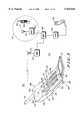
- FIG. 1is an illustration showing a communication system comprising a modular communication device and a base station, the modular communication device including a first modular unit and a second modular unit shown unconnected.
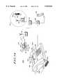
- FIG. 2is an illustration showing the modular communication device with the first modular unit and the second modular unit shown connected.
- FIG. 3is an illustration showing a rear plan view of the first modular unit, and a battery for operating the first modular unit.
- FIG. 4is an illustration showing a rear plan view of the second modular unit.
- FIG. 5is an illustration showing a rear plan view of a battery pack that connects to the second modular unit.
- FIG. 6is a schematic diagram of electrical circuitry of the modular communication device and electrical components of battery pack.
- FIG. 7shows a timing diagram of a time division multiplex (TDM) communication system.
- FIG. 8is a chart showing a first current drain of the modular communication device.
- FIG. 9is a chart showing a second current drain of the modular communication device.
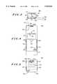
- FIG. 10is a diagram showing a first frame structure of the communication system.
- FIG. 11is a diagram showing a second frame structure of the communication system.
- FIG. 12is a flowchart describing a first method of operating the modular communication device.
- FIG. 13is a flowchart describing a second method of operating the modular communication device.
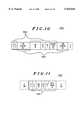
- FIG. 14is an illustration showing a third modular unit that is configured to receive the first modular unit.
- FIG. 15is an illustration showing a first alternate embodiment of a modular communication device, the modular communication device including a first modular unit and a second modular unit shown unconnected.
- FIG. 16is an illustration showing the first alternate embodiment of the modular communication device where the first modular unit and the second modular unit are shown connected.
- FIG. 17is an illustration showing a second alternate embodiment of a modular communication device.
- FIG. 1is an illustration of a communication system 100 comprising a modular communication device 102 and a base station 104.
- Modular communication device 102communicates with base station 104 via radio frequency (RF) signals when located within a coverage area of base station 104.
- Base station 104may be a part of a conventional cellular or cellular-like communication system.
- Base station 104is coupled to a mobile telephone switching office (MTSO) 156, which is in turn coupled to a public switched telephone network (PSTN) 158.
- MTSOmobile telephone switching office
- PSTNpublic switched telephone network
- Communication system 100may also include other base stations, such as a base station 152 having an antenna 154 and serving a coverage area 153.
- Other communication devicessuch as a mobile station 162 having an antenna 164, may also communicate via RF signals within communication system 100.
- conventional fixed telephone units that are coupled to PSTN 158 through land line connections, such as a fixed telephone unit 160may also communicate within communication system 100.
- Modular communication device 102includes a first modular unit 106 and a second modular unit 108.
- First modular unit 106comprises a housing 110, a user interface 113, and a connection interface 120.
- Housing 110defines a front side 124 and a back side 126, and includes a battery compartment 112.
- User interface 113includes a display 114 and keys 116 which are both directed outwardly from front side 124.
- Connection interface 120is provided on back side 126 and includes electrical contacts 122.
- FIG. 3is an illustration showing a rear plan view of first modular unit 106.
- connection interface 120 having electrical contacts 122is shown in better detail.
- FIG. 3also shows that battery compartment 112 is used for storing a battery 302, which is preferably a AAA-size battery with an operating voltage of 1.5 volts.
- a battery connection interface 308is provided within battery compartment 112 and includes electrical contacts 304 and 306. Dashed lines within battery compartment 112, which illustrate the positioning of battery 302 when properly inserted therein, show that battery contacts of battery 302 make electrical contact with electrical contacts 304 of battery connection interface 308.
- second modular unit 108comprises a housing 128, a keypad cover 131, a user interface 135, a retractable antenna 134, a connection interface 143, and a battery connection interface (not visible in FIG. 1) for attaching a battery pack 142.
- Housing 128defines a front side 130 and back side 132.
- User interface 135includes a speaker disposed in housing 128 and directed outward from front side 130 through a speaker grille 136, a microphone disposed in housing 128 and directed outward from front side 130 through a hole 138, and a keypad 140.
- Keypad cover 131shown in an open position in FIG. 1, is capable of opening and closing to expose and cover keypad 140.
- Retractable antenna 134partially retracts within housing 128 and is shown in a non-retracted position.
- FIG. 4shows a rear plan view of second modular unit 108 and a battery connection interface 402 thereof, without battery pack 142 being attached thereto.
- battery connection interface 402includes electrical contacts 404, guide rails 405 and 406, guide rails 407 and 408, and a slot 410.
- battery pack 142includes battery cells and associated circuitry 512 disposed therein.
- Battery pack 142includes a connection interface 166 that includes electrical contacts 168 that are coupled to battery cells and associated circuitry 512.
- battery pack 142has a connection interface 500 configured to attach to battery connection interface 402 of first modular unit 106 (FIG. 4).
- Connection interface 500includes electrical contacts 502, guide rails 507 and 508, guide rails 509 and 510, and a latching mechanism 504 having a button portion 505 and a catch 506.
- battery pack 142may be slid on and attached to second modular unit 108.
- each of electrical contacts 502 of battery pack 142make electrical contact with one of electrical contacts 404 of second modular unit 108.
- catch 506is engaged within slot 506.
- Guild rails 507 and 508 of battery pack 142are disposed opposite and captivated beneath guide rails 407 and 408 of second modular unit 106.
- guide rails 509 and 510 of battery pack 142are disposed opposite and captivated beneath guide rails 405 and 406 of second modular unit 108.
- button portion 505is pressed in a direction toward second modular unit 108, thereby causing a twisting of latching mechanism 504 where catch 506 retracts from slot 410.
- Battery pack 105may then be slid along the direction of guide rails 405, 406, 407, and 408 until lifted and detached.
- Second modular unit 108may be alternatively constructed such that battery cells and associated circuitry 512 are disposed within housing 128.
- battery pack 142 and battery connection interface 402are unneccesary.
- housing 128defines an opening on back side 132 that exposes an accessory connector 400.
- Accessory connector 400includes electrical contacts and provides an interface to an accessory unit such as a facsimile machine, a modem, an additional power source, etc.
- second modular unit 108is configured to receive first modular unit 106.
- Connection interface 143 of second modular unit 108includes an opening 144 and electrical contacts 146 disposed within opening 144.
- Housing 106is sized to pressure-fit within opening 144 of connection interface 143.
- connection interfaces 120 and 143connect where electrical contacts 122 make electrical contact with electrical contacts 146.
- FIG. 2shows first modular unit 106 received within second modular unit 108. As shown, display 114 and the plurality of keys 116 of first modular unit 106 are directed outward from front side 130 of second modular unit 108. Front side 124 of first modular unit 106 and front side 130 of second modular unit 108 are substantially flush.
- housing 110 of first modular unit 106is sized to fit within a user's palm and may be comfortably attached to a user's clothing with a conventional belt clip.
- housing 128 of second modular unit 108is sized larger than housing 110, and more particularly, sized to fit within a user's hand where speaker grille 136 and hole 138 are distanced appropriately to provide proper ergonomics for conventional two-way telephone or telephone-like communication.
- first modular unit 102when used without second modular unit 108, is independently operable and provides limited communication capability for a user thereof.
- communication device 102When used with second modular unit 108, communication device 102 provides expanded communication capability for the user.
- FIG. 6is a schematic block diagram of modular communication device 102, including electrical circuitry 602 of first modular unit 106, electrical components 647 of second modular unit 108, and electrical components 656 of battery pack 142.
- Electrical circuitry 602includes a processor 604, used to process signals and to control a large portion of electrical circuitry 602; a transceiver 606, including a receiver 622 and a transmitter 624, used for receiving and transmitting RF signals; an antenna 610; switching circuitry 612, used to switchably couple antenna 610 to transceiver 606; power management circuitry 608, used to provide and control electrical power to electrical circuitry 602; a duplexer 614, used to appropriately switch antenna 610 in receive and transmit modes of transceiver 606; key circuitry 616, used to generate signals to processor 604 in response to actuations of keys 116 (FIG. 1); display circuitry 618, used to translate signals from processor 604 to control and operate display 114 (FIG. 1); and alert circuitry 620, used to provide audible alert signals in response to signals from processor 604. As shown, most of electrical contacts 122 of connection interface 120 are coupled to processor 604.
- battery cell 302When first modular unit 106 is not attached to second modular unit 108, battery cell 302 provides the necessary power to operate electrical circuitry 602. When attached to battery connection interface 308, battery cell 302 is coupled to power management circuitry 608.
- Power management circuitry 608includes charger/booster circuitry 630, a capacitor 632, switching circuitry 634, and switching circuitry 636. Processor 604 maintains switching circuitry 636 to provide power from battery cell 302.
- Power management circuitry 608provides a regulated supply voltage V for most of electrical circuitry 602.
- battery cell 302has a voltage that, in itself, is too low to operate a power amplifier 628 of transceiver 606 during amplification. Therefore, during a time period before power amplifer 628 amplifies, charger/booster circuitry 630 charges capacitor 632 with a charge sufficient to operate power amplifier 628 during amplification. When capacitor 632 is sufficiently charged and amplification is necessary, processor controls switching circuitry 634 to discharge capacitor 632. Thus, at least during a substantial portion of amplification, power amplifer 628 is biased at a voltage V PA that is greater than regulated supply voltage V.
- capacitor 632is a supercapacitor having a relatively large capacitance.
- antenna 610is coupled to transceiver 606 through switching circuitry 612. Through antenna 610, receiver 622 receives RF signals from base station 104.
- Base station 104typically generates RF signals having control data, voice, and/or short messaging data modulated thereon.
- Receiver 622may receive an RF signal having a paging message modulated thereon, where the paging message is uniquely intended for first modular unit 106.
- Receiver 622demodulates such an RF signal and provides data at processor 604 for interpretation.
- Processor 604decodes the data and, after determining that the paging message was uniquely intended for first modular unit 106, provides an audible alert signal through alert circuitry 620.
- Transmitter 624includes a modulator 626 and power amplifer 628. Transmitter 624 typically receives data from processor 604, modulates the data with RF signals, amplifies the RF signals through power amplifer 628, and transmits the amplified RF signals through antenna 610 when first modular unit 106 is operating without second modular unit 108.
- Electrical components 647 of second modular unit 108include a microphone 648, a speaker 650, a keypad interface circuit 652, antenna 134, and accessory connector 400. Electrical components 647 are coupled to electrical contacts 146 of connection interface 144.
- Battery cells and associated circuitry 512 of battery pack 142include battery cells 654, a memory 658 for storing battery identification parameters, and a thermistor 660 providing an indication of the temperature of battery pack 142. Battery cells and associated circuitry 512 are coupled to electrical contacts 502 of connection interface 500 and to electrical contacts 168 of connection interface 166.
- connection interface 120 of first modular unit 106 and connection interface 144 of second modular unit 108are connected, electrical components 647 are coupled to electrical circuitry 602.
- Processor 604detects the presence of second modular unit 108. Such detection may be performed with any suitable method, such as with a line 638 that is coupled to battery cells 654. In response to such detection, processor 604 controls switching circuitry 636 to switch from using battery cell 302 to using battery cells 654 to power electrical circuitry 602. Electrical circuitry 602 is thereby provided with battery cells 654 having a greater supply voltage and capacity. In addition, processor 604 controls switching circuitry 612 to switch from using antenna 610 to using antenna 134 for receiving and transmitting RF signals.
- processor 604provides electrical signals at speaker 650 to provide voice audio of a called or calling party, receives electrical signals from microphone 648 generated from voice audio of the user, and receives signals from keypad interface circuitry 652 generated by key actuations at keypad 140.
- FIG. 6also illustrates a battery charger 662 that includes battery charging circuitry 666, a battery charger interface 664 having electrical contacts 663, and an electrical cord 668 having a transformer plug 670 on an end thereof.
- Transformer plug 670is configured for insertion into an alternating current (AC) outlet 672, where battery charging circuitry 666 receives its power for operating and charging battery pack 142.
- ACalternating current
- connection interface 166is connected to charging interface 664 where electrical contacts 168 make electrical contact with electrical contacts 663.
- communication system 100preferably provides RF communication in accordance with a time-division multiplexed (TDM) protocol.
- TDMtime-division multiplexed
- protocolsinclude protocols defined by RCR-27D, which is used in a Personal Digital Cellular (PDC) system, or defined by IS-136, which is used in a North American Digital Cellular (NADC) system.
- RCR-27Dwhich is used in a Personal Digital Cellular (PDC) system
- IS-136which is used in a North American Digital Cellular (NADC) system.
- FIG. 7shows time slots 700 that are representative of a PDC system protocol.
- first modular unit 106is assigned to time slots 702 and 708, while time slots 704 and 706 are assigned to other communication devices located within the coverage area of base station 104.
- FIG. 10shows a data slot 1000 used for transmission when sending voice information to base station 104.
- Data slot 1000comprises predefined functional channels including system overhead data 1002 and information data 1004.
- a data slot for sending short messaging information to base station 104has predefined functional channels that are similar to those of data slot 1000.
- FIG. 11shows a data slot 1100 used for transmission when no audible signals are present at a mobile station during voice communication.
- Data slot 1100comprises predefined functional channels including system overhead data 1102. Since no voice data needs to be sent, data slot 1100 contains no information data similar to information data 1004 of data slot 1000 (FIG. 10).
- Data slots such as data slot 1100are typically used in systems having voice-activated transmission (VOX) capability.
- VOXvoice-activated transmission
- FIG. 8shows a first current drain of modular communication device 102, taken at points 644 and 646 of electrical circuitry 602.
- the first current drainis representative of transceiver 606 (FIG. 6) receiving and transmitting within time slots 700 (FIG. 7) when sending data slots such as data slot 1000.
- FIG. 9shows a second current drain of modular communication device 102, also taken at points 644 and 646 of electrical circuitry 602.
- the second current drainis representative of transceiver 606 (FIG. 6) receiving and transmitting within time slots 700 (FIG. 7) when sending data slots such as data slot 1100.
- power amplifier 628amplifies for an amplification period L 1 during a transmit slot 726 when transmitting data slot 1000 (FIG. 10).
- power amplifier 628amplifies for an amplification period L 2 during transmit slot 726 when transmitting data slot 1100 (FIG. 11).
- amplification period L 2is shorter than amplification period L 1 .
- FIG. 12is a flowchart of a method of providing communications for modular communication device 102. This method requires no changes to existing air interface specifications or to existing software in base station 104.
- first modular unit 106is not connected to second modular unit 108.
- first modular unit 106registers with base station 104 (step 1202).
- First modular unit 106enters into a standby mode, waiting for an incoming call to be received from a calling unit, such as fixed telephone unit 160 or mobile station 162 (step 1204). If an incoming call is received, first modular unit 106 establishes a traffic channel with base station 104 (step 1206).
- first modular unit 106alerts the user through alerting circuit 620 or by vibration (step 1210). If a caller ID option is available, base station 104 sends caller ID information and a telephone number from the calling unit is displayed on display 114. Using keys 116, the user may select from a number of options to respond to the call. Alternatively, the number of options are programmable and preset by the user.
- base station 104plays a first predetermined message to the calling unit, which notifies the calling party to wait (step 1236). During this time, the user of first modular unit 106 wishes to retrieve second modular unit 108 for connecting with first modular unit 106. During the waiting period, first modular unit 106 repeatedly transmits shortened data bursts during its transmit times slots, the shortened data bursts including only the data necessary to maintain the call (step 1238). For example, first modular unit 106 transmits data slots such as data slot 1100 of FIG. 11 during the waiting period.
- first modular unit 106sends normal data bursts containing information data such as voice data (step 1242). For example, first modular unit 106 transmits data slots such as data slot 1000 during this time period.
- a conventional, two-way, full-duplex voice callproceeds (step 1244).
- step 1214If a different option is selected (step 1214), such as a call forwarding option (step 1218), the call is forwarded to a selected or preselected telephone number (step 1220).
- a different optionsuch as a call forwarding option (step 1218)
- the callis forwarded to a selected or preselected telephone number (step 1220).
- a second predetermined messageis played to the calling unit which instructs the caller to leave a message (step 1226).
- Base station 104may optionally send the caller ID information at this time, and first modular unit 106 stores the caller ID and other call statistics, such as the date and the time of the call (step 1228).
- the calling unitproceeds to leave a voice message (or alphanumeric message), which first modular unit 106 stores in memory 605.
- a third predetermined messageis played to the calling unit, which provides the caller with a selection of predetermined short messages to leave for first modular unit 106 (step 1228).
- the selected predetermined short messageis sent from base station 104 to first modular unit 106 where it is stored in memory 605 (step 1230).
- one of the predetermined short messagesmay provide a written message in display 114 reading "URGENT--PLEASE CALL BACK.”
- FIG. 13is a flowchart of another method of providing communications for modular communication device 102. This method requires no changes to existing air interface specifications but may require a change in existing software of base station 104.
- first modular unit 106is not connected to second modular unit 108.
- first modular unit 106registers with base station 104 as a limited function unit (step 1302).
- First modular unit 106enters into a standby mode, waiting for an incoming call to be received from a calling unit, such as fixed telephone unit 160 or mobile station 162 (step 1304). If an incoming call is received, MSTO 156 informs the calling unit that modular communication device 102 has limited functionality (step 1304). Options are provided for the calling unit, such as a call request option and a message request option.
- base station 104sends a short message to first modular unit 106 for a call request (step 1312).
- Base station 104may optionally send caller ID information (step 1314).
- first modular unit 106may provide an alert indication for the user.
- first modular unit 106has a number of options for responding thereto. If the user selects a pick-up request option (step 1316), then first modular unit 106 sends a short message to base station 104 (step 1330) to inform the calling unit to wait (step 1332). Here, first modular unit 106 establishes a traffic channel with base station 104. During this time, the user of first modular unit 106 wishes to retrieve second modular unit 108 for connecting with first modular unit 106. During the waiting period, first modular unit 106 repeatedly transmits shortened data bursts during its transmit times slots, the shortened data bursts including only the data necessary to maintain the call (step 1333). For example, first modular unit 106 transmits data slots such as data slot 1100 of FIG.
- first modular unit 106sends normal data bursts containing information data such as voice data (step 1337). For example, first modular unit 106 transmits data slots such as data slot 1000 during this time period.
- a conventional, two-way, full-duplex voice callproceeds (step 1338).
- a second predetermined messageis played to the calling unit which instructs the caller to leave a message.
- the calling unitproceeds to leave a voice message (or alphanumeric message) (step 1326).
- Base station 104proceeds to send a short message to first modular unit 106 informing that a message was sent (step 1328).
- first modular unit 106sends a short message to base station 104 (step 1340).
- the calling unitis played a predetermined message corresponding to the short message sent (step 1342).
- first modular unit 106may also be configured for attachment to a third modular unit 1402 of a wireline unit system 1400.
- second modular unit 1402includes a housing 1404, a user interface 1404, a connection interface 1414, and electrical circuitry 1422 disposed within housing 1404.
- User interface 1405includes a handset 1406 and a keypad 1420.
- Handset 1406includes a speaker 1408 and a microphone 1410 (both not visible), and is physically and electrical connected to housing 1404 and electrical circuitry 1422, respectively, through a cord 1412.
- Connection interface 1414includes an opening 1416 having electrical contacts 1418 therein and a recess 1417 along an edge of opening 1416. Connection interface 1414 is configured for attachment to connection interface 120 of first modular unit 106, as similarly described in relation to FIGS. 1 and 2. When first modular unit 106 is received within opening 1416, electrical contacts 122 make electrical contact with electrical contacts 1418,
- FIG. 15is illustration of an isometric view of a modular communication device 1500 including a first modular unit 1502 and a second modular unit 1504.
- First modular unit 1502includes a housing 1504, a user interface 1505, an antenna 1514, a battery compartment 1512, and a connection interface 1516.
- User interface 1505includes a display 1508, a keypad 1510, and a speaker disposed within housing 1504 and directed outward from an earpiece 1506.
- first modular unit 1702includes electrical circuitry disposed within housing 1504.
- First modular unit 1502operates similarly if not the same as first modular unit 106 of FIG. 1, and the electrical circuitry therein is similar to electrical circuitry 602 of FIG. 6.
- first modular unit 1502While first modular unit 1502 is detached from second modular unit 1504, the speaker of first modular unit 1502 may be used to provide audio signals in a variety of applications.
- the speakermay be used to provide alert signals in response to received calls, to provide voice or data signals received over the communication channel, or to provide data or voice signals received via short messaging.
- Second modular unit 1504includes a housing 1520, a user interface 1521, a battery connection interface (not visible) for attaching a battery 1524, a connection interface 1532, and a hinging mechanism 1525.
- User interface 1521includes a microphone disposed within housing 1520 and directed outward from a hole 1522.
- Hinging mechanism 1525includes arms 1528 and 1530 and a cylindrical portion 1526 that is rotatably coupled to housing 1520 via arms 1528 and 1530.
- Connection interface 1532includes members 1536 having electrical contacts 1534 that are coupled to battery 1524 through the battery connection interface and to the microphone disposed within housing 1520. In the embodiment shown, connection interface 1532 is coupled to cylindrical portion 1526 of hinging mechanism 1525.
- modular communication device 1500provides the appropriate user interface and physical dimensions for telephone or telephone-like communication.
- the electrical circuitry within first modular unit 1502receives electrical signals from the microphone of second modular unit 1504 (generated by voice signals of a user thereof), and provides electrical signals to the speaker of first modular unit 1502 to provide audio signals therefrom.
- battery 1524modular communication device 1500 also provides adequate power for such full-duplex voice communication.
- FIG. 17is an illustration of an isometric view of a modular communication device 1700.
- Modular communication device 1700includes a first modular unit 1702 and a second modular unit 1704 which are shown detached in FIG. 17.
- First modular unit 1702includes a housing 1722, a user interface 1723, an antenna 1730, a battery compartment 1732, and a connection interface 1734.
- User interface 1723includes a display 1724, a keypad 1726, and a microphone disposed within housing 1722 and directed outward from a hole 1728.
- first modular unit 1702includes electrical circuitry disposed within housing 1722.
- First modular unit 1702operates similarly if not the same as first modular unit 106 of FIG. 1, and the electrical circuitry therein is similar to electrical circuitry 602 of FIG. 6.
- Microphone 1728may be used for recording or storing audible signals, which are later processed and sent to another communication device via short messaging protocols. Alternatively, or in combination with such recording or storing feature, microphone 1728 may be used for inputting voice data and commands for operating first modular unit 106. With any of these options, an appropriate memory or storage device would accomodate first modular unit 1702.
- Second modular unit 1704includes a housing 1706, a user interface 1707, a battery connection interface (not visible) for attaching a battery 1710, a connection interface 1712, and a hinging mechanism 1713.
- User interface 1707includes a speaker disposed within housing 1706 and directed outward from an earpiece 1708.
- Hinging mechanism 1713includes arms 1714 and 1716 and a cylindrical portion 1718 that is rotatably coupled to housing 1706 via arms 1714 and 1716.
- Connection interface 1712includes members 1718 having electrical contacts 1720 that are coupled to battery 1710 through the battery connection interface and to the speaker disposed within housing 1706. In the embodiment shown, connection interface 1712 is coupled to cylindrical portion 1718 of hinging mechanism 1713.
- second modular unit 1702When first modular unit 1702 is attached to second modular unit 1704, second modular unit 1702 may open and close about an axis defined by hinging mechanism 1713, as shown by an arrow 1740.
- connection interfaces 1712 and 1734the speaker of second modular unit 1704 and battery 1710 are coupled to the electrical circuitry of first modular unit 1702.
- modular communication device 1700provides the appropriate user interface and physical dimensions for telephone or telephone-like communication.
- the electrical circuitry of first modular unit 1702provides electrical signals to the speaker of second modular unit 1704 to provide audio signals therefrom, and receives electrical signals from the microphone of first modular unit 1502.
- modular communication device 1700With battery 1710, modular communication device 1700 also provides adequate power for such full-duplex voice communication.
- communication system 100may be a code division multiple access (CDMA) system or a group special mobile (GSM) system.
- Communciation system 100is not required to be a digital system, but may be an analog system such as Advanced Mobile Phone System (AMPS) or Narrowband Advanced Mobile Phone System (NAMPS). It is therefore intended in the appended claims to cover all such changes and modifications which fall within the true spirit and scope of the invention.
- CDMAcode division multiple access
- GSMgroup special mobile
- Communciation system 100is not required to be a digital system, but may be an analog system such as Advanced Mobile Phone System (AMPS) or Narrowband Advanced Mobile Phone System (NAMPS). It is therefore intended in the appended claims to cover all such changes and modifications which fall within the true spirit and scope of the invention.
- AMPSAdvanced Mobile Phone System
- NAMPSNarrowband Advanced Mobile Phone System
Landscapes
- Engineering & Computer Science (AREA)
- Signal Processing (AREA)
- Computer Networks & Wireless Communication (AREA)
- Human Computer Interaction (AREA)
- Mobile Radio Communication Systems (AREA)
- Transceivers (AREA)
- Telephone Set Structure (AREA)
Abstract
Description
Claims (32)
Priority Applications (4)
| Application Number | Priority Date | Filing Date | Title |
|---|---|---|---|
| US08/806,979US5924044A (en) | 1997-02-26 | 1997-02-26 | Modular communication device and method of providing communications therewith |
| GB9801288AGB2324227A (en) | 1997-02-26 | 1998-01-21 | Modular communication device |
| DE19804746ADE19804746A1 (en) | 1997-02-26 | 1998-02-06 | Modular data transmission device and method of ensuring data transmission therewith |
| JP10052940AJPH10243441A (en) | 1997-02-26 | 1998-02-18 | Modular communication equipment and method for making communication by using it |
Applications Claiming Priority (1)
| Application Number | Priority Date | Filing Date | Title |
|---|---|---|---|
| US08/806,979US5924044A (en) | 1997-02-26 | 1997-02-26 | Modular communication device and method of providing communications therewith |
Publications (1)
| Publication Number | Publication Date |
|---|---|
| US5924044Atrue US5924044A (en) | 1999-07-13 |
Family
ID=25195279
Family Applications (1)
| Application Number | Title | Priority Date | Filing Date |
|---|---|---|---|
| US08/806,979Expired - LifetimeUS5924044A (en) | 1997-02-26 | 1997-02-26 | Modular communication device and method of providing communications therewith |
Country Status (4)
| Country | Link |
|---|---|
| US (1) | US5924044A (en) |
| JP (1) | JPH10243441A (en) |
| DE (1) | DE19804746A1 (en) |
| GB (1) | GB2324227A (en) |
Cited By (71)
| Publication number | Priority date | Publication date | Assignee | Title |
|---|---|---|---|---|
| US6069593A (en)* | 1998-02-24 | 2000-05-30 | Motorola, Inc. | Display carrier and electronic display control for multiple displays in a portable electronic device |
| US6115616A (en)* | 1998-05-28 | 2000-09-05 | International Business Machines Corporation | Hand held telephone set with separable keyboard |
| US6163691A (en)* | 1998-06-24 | 2000-12-19 | Uniden America Corporation | Caller identification in a radio communication system |
| WO2000078020A1 (en)* | 1999-06-14 | 2000-12-21 | Telular Corp. | Method and apparatus for display of caller id and cellular extended information on a fixed wireless terminal |
| US6181956B1 (en)* | 1998-08-03 | 2001-01-30 | Motorola, Inc. | Communication device with selective message transfer to earpiece |
| US6216017B1 (en)* | 1997-11-06 | 2001-04-10 | Samsung Electronics Co., Ltd. | Separable cellular telephone and method for operating the same |
| US6219257B1 (en)* | 1998-05-07 | 2001-04-17 | Conexant Systems, Inc. | Integrated battery compartment and hinge |
| US6240302B1 (en)* | 1998-05-29 | 2001-05-29 | 3Com Corporation | Wireless phone with removable personal information manager |
| US6244894B1 (en)* | 1999-03-02 | 2001-06-12 | Nec Corporation | Cellular phone battery equipped with IC card |
| WO2001050618A1 (en)* | 2000-01-05 | 2001-07-12 | Vox2, Inc. | Cellular telephone docking station |
| US6266542B1 (en)* | 1998-09-24 | 2001-07-24 | Ericsson Inc. | Accessory allowing hands-free operation of a cellular telephone |
| US6275690B1 (en)* | 1996-12-27 | 2001-08-14 | Hitachi, Ltd. | Cellular mobile telephone apparatus |
| US6311057B1 (en)* | 1996-06-27 | 2001-10-30 | Telefonaktiebolaget Lm Ericsson(Publ) | Method of calling a mobile station in a mobile telephone system |
| US6353730B1 (en) | 1998-06-24 | 2002-03-05 | Uniden America Corporation | Automatic call to page conversion in a radio communication system |
| WO2002023868A1 (en)* | 2000-09-15 | 2002-03-21 | Polti S.P.A. | Double-acting telecommunication apparatus for mobile telephony |
| US20020042291A1 (en)* | 2000-10-11 | 2002-04-11 | Markku Lahteenmaki | Communication device |
| US6374114B1 (en)* | 1998-08-04 | 2002-04-16 | Ericsson Inc. | Methods of processing and transmitting incoming call pages including information allowing a determination of the time allowed for response and related user terminals and communications systems |
| US20020050981A1 (en)* | 2000-09-01 | 2002-05-02 | Frank Nuovo | Portable communication device |
| WO2002056573A1 (en)* | 2001-01-16 | 2002-07-18 | Siemens Aktiengesellschaft | Wireless terminal |
| US20020114467A1 (en)* | 1998-09-04 | 2002-08-22 | Harri Vatanen | Security module, security system and mobile station |
| US20020123375A1 (en)* | 2001-03-02 | 2002-09-05 | Shu Shimazaki | Mobile phone |
| US20020164979A1 (en)* | 2001-05-01 | 2002-11-07 | Mooney Philip D. | Wireless phone forwarding based on phone location |
| WO2003009485A1 (en)* | 2001-07-17 | 2003-01-30 | Wildseed, Ltd. | Interchangeable covering with keys for personalizing mobile electronic communication devices |
| WO2003017514A1 (en)* | 2001-08-13 | 2003-02-27 | Motorola, Inc. | Voice announced caller identification features and methods therefor |
| US6625030B1 (en)* | 2000-04-07 | 2003-09-23 | Mobicom Corporation | Wireless terminal assembly |
| US6628961B1 (en)* | 1999-08-06 | 2003-09-30 | Inventec Electronics (Shanghai) Co., Ltd. | Device and a method for connecting a mobile phone handset to an external keyboard |
| US20030195014A1 (en)* | 1998-02-10 | 2003-10-16 | Shinichiro Mori | Mobile telephone set and data communication adaptor |
| US20030211863A1 (en)* | 2000-06-02 | 2003-11-13 | Wolfgang Neifer | Accumulator with reading device |
| US20030227745A1 (en)* | 2002-06-10 | 2003-12-11 | Khoo Soon Huat | Compound portable computing device with dual portion keyboard coupled over a wireless link |
| US6690949B1 (en)* | 1999-09-30 | 2004-02-10 | Skyworks Solutions, Inc. | System and process for supporting multiple wireless standards with a single circuit architecture |
| US6725060B1 (en)* | 2000-02-15 | 2004-04-20 | Qualcomm, Incorporated | Method and apparatus for conserving power in an integrated electronic device that includes a PDA and A wireless telephone |
| US20040097264A1 (en)* | 1998-03-31 | 2004-05-20 | Starfish Software, Inc. | Enhanced companion digital organizer for a cellular phone device |
| US20040102183A1 (en)* | 2002-11-21 | 2004-05-27 | David Haub | Mobile wireless communications device enablement and methods therefor |
| US6760600B2 (en)* | 1999-01-27 | 2004-07-06 | Gateway, Inc. | Portable communication apparatus |
| US6792298B1 (en)* | 1999-05-05 | 2004-09-14 | Siemens Aktiengesellschaft | Telephone terminal to control functions and enter digits |
| US20040185855A1 (en)* | 2002-12-31 | 2004-09-23 | Storm Brian D. | Method and apparatus for continuing a call |
| US6823182B1 (en) | 1996-12-27 | 2004-11-23 | Hitachi, Ltd. | Cellular mobile telephone apparatus |
| US6823196B1 (en)* | 1999-04-07 | 2004-11-23 | Sharp Kabushiki Kaisha | Multi-mode communication apparatus and method including multiple transmitter sections |
| WO2004110038A1 (en)* | 2003-06-05 | 2004-12-16 | Motorola Inc | Two-part radio communications device |
| US20050143150A1 (en)* | 2002-02-06 | 2005-06-30 | Lite-On Technology | Electricity saving device for a user interface terminal device of cellular phone |
| US20050192061A1 (en)* | 2004-03-01 | 2005-09-01 | Research In Motion Limited | Communications system providing automatic text-to-speech conversion features and related methods |
| US20050191994A1 (en)* | 2004-03-01 | 2005-09-01 | Research In Motion Limited, A Canadian Corporation | Communications system providing text-to-speech message conversion features using audio filter parameters and related methods |
| US6952617B1 (en)* | 1999-07-15 | 2005-10-04 | Khyber Technologies Corporation | Handheld computer with detachable handset |
| EP1587334A1 (en)* | 2004-04-16 | 2005-10-19 | Research In Motion Limited | Portable Alerter for Wireless Device |
| US20050233774A1 (en)* | 2004-04-16 | 2005-10-20 | Research In Motion Limited | Portable alerter for wireless device |
| US20050263604A1 (en)* | 1997-04-25 | 2005-12-01 | Minerva Industries, Inc. | Mobile entertainment and communication device |
| WO2005025242A3 (en)* | 2003-08-25 | 2006-02-23 | Motorola Inc | System and method for transmitting caller information from a source to a destination |
| US7010325B1 (en) | 2002-06-11 | 2006-03-07 | Sprint Spectrum L.P. | Wireless repeater with wireless telephone adapter |
| US20060105722A1 (en)* | 2002-05-29 | 2006-05-18 | Rajendra Kumar | Portable data entry device with a detachable host pda |
| US20060160567A1 (en)* | 2004-03-19 | 2006-07-20 | Jamshid Parivash | Integrated detachable PDA and cellular phone |
| US20060170656A1 (en)* | 2005-01-29 | 2006-08-03 | Lg Electronics Inc. | Mobile station with satellite antenna |
| US7095986B2 (en) | 2001-07-17 | 2006-08-22 | Wildseed Ltd. | Interchangeable covering with keys for personalizing mobile electronic communication devices |
| US7146189B1 (en)* | 2000-07-11 | 2006-12-05 | Motorola, Inc. | Apparatus for wireless device to alter performance of wireless communication link |
| US7162020B1 (en) | 1999-06-14 | 2007-01-09 | Ascendent Telecommunications, Inc. | Method and apparatus for selectively establishing communication with one of plural devices associated with a single telephone number |
| US7221961B1 (en) | 1999-06-14 | 2007-05-22 | Ntt Docomo, Inc. | Wireless telecommunications unit attachable to and detachable from an external unit |
| US7292858B2 (en) | 1999-06-14 | 2007-11-06 | Ascendent Telecommunications, Inc. | Method and apparatus for communicating with one of plural devices associated with a single telephone number during a disaster and disaster recovery |
| US7305079B1 (en) | 1999-06-14 | 2007-12-04 | Ascendent Telecommunications, Inc. | Method and apparatus for communicating with one of plural devices associated with a single telephone number |
| US20080048986A1 (en)* | 2002-06-10 | 2008-02-28 | Khoo Soon H | Compound Computing Device with Dual Portion Keyboards Controlled by a Single Processing Element |
| US20080146284A1 (en)* | 2006-12-18 | 2008-06-19 | Stone Samuel W | Mini cell phone adapter and method for extending the function of a mini cell phone |
| US20080166984A1 (en)* | 2007-01-09 | 2008-07-10 | Terrence John Shie | Multiband or multimode receiver with shared bias circuit |
| WO2009089393A1 (en) | 2008-01-10 | 2009-07-16 | Aria Enterprises, Inc. | Customizable modular multi-function communication device |
| WO2009156555A1 (en)* | 2008-06-27 | 2009-12-30 | Nokia Corporation | Apparatus, add-on module, and a system comprising a host apparatus and an add-on module |
| US20100210318A1 (en)* | 2009-02-16 | 2010-08-19 | Research In Motion Limited | Mobile wireless communications device including a self-contained rechargeable battery pack with filter and related methods |
| EP1884144A4 (en)* | 2005-02-11 | 2010-11-24 | Plantronics | System for adapting devices |
| US20110165919A1 (en)* | 2009-10-09 | 2011-07-07 | Motorola Mobility, Inc. | Radiotelephone module and devices containing same |
| US20110230163A1 (en)* | 2003-11-10 | 2011-09-22 | Research In Motion Limited | Methods and apparatus for limiting communication capabilities in mobile communication devices |
| US20120225622A1 (en)* | 2011-03-04 | 2012-09-06 | Research In Motion Limited | Separable mobile device having a control module and a docking station module |
| US8842106B2 (en)* | 2000-08-11 | 2014-09-23 | Drnc Holdings, Inc. | Portable telephone |
| US20150077907A1 (en)* | 2012-04-12 | 2015-03-19 | Tyco Electronics Amp Gmbh | System for the contactless data supply of bus participant modules |
| US9942377B2 (en) | 2000-08-11 | 2018-04-10 | Drnc Holdings, Inc. | Portable telephone |
| US11011153B2 (en) | 2004-03-01 | 2021-05-18 | Blackberry Limited | Communications system providing automatic text-to-speech conversion features and related methods |
Families Citing this family (4)
| Publication number | Priority date | Publication date | Assignee | Title |
|---|---|---|---|---|
| JP3951882B2 (en)* | 2001-11-02 | 2007-08-01 | カシオ計算機株式会社 | Wireless communication terminal and communication control program |
| GB2386496A (en)* | 2002-03-11 | 2003-09-17 | Sendo Int Ltd | Interchangable cover for a communication device |
| KR100769526B1 (en)* | 2003-10-30 | 2007-10-23 | 보다폰 가부시키가이샤 | Mobile communication terminal apparatus, core module for mobile communication terminal apparatus, and function module for mobile communication terminal apparatus |
| US11606451B2 (en) | 2020-09-30 | 2023-03-14 | Rockwell Collins, Inc. | Smartphone with integrated pager |
Citations (19)
| Publication number | Priority date | Publication date | Assignee | Title |
|---|---|---|---|---|
| EP0263666A2 (en)* | 1986-10-06 | 1988-04-13 | Kabushiki Kaisha Toshiba | Cordless telephone apparatus |
| US4941203A (en)* | 1988-09-12 | 1990-07-10 | Motorola, Inc. | Two-way radio communication system having selectable operating modes |
| US5020090A (en)* | 1989-11-13 | 1991-05-28 | Intelligence Technology Corporation | Apparatus for removably connecting a cellular portable telephone to a computer |
| US5109539A (en)* | 1989-03-31 | 1992-04-28 | Mitsubishi Denki Kabushiki Kaisha | Portable communication device |
| EP0521609A2 (en)* | 1991-05-30 | 1993-01-07 | Nokia Mobile Phones Ltd. | Radio phone composable of separate modules |
| US5197092A (en)* | 1990-10-31 | 1993-03-23 | Mccaw Cellular Communications, Inc. | Location registration system for a personal communicator such as a cellular telephone |
| US5259018A (en)* | 1989-03-17 | 1993-11-02 | Technophone Limited | Radio telephone system having a handset adapted to be removably connected and containing a NAM for storing a telephone number identifying the handset |
| US5303291A (en)* | 1990-09-07 | 1994-04-12 | Fujitsu Limited | Portable telephone having a detachable functional module |
| EP0613257A2 (en)* | 1993-02-26 | 1994-08-31 | Sony Corporation | Power circuit and radiocommunication apparatus using the power circuit |
| US5365573A (en)* | 1992-03-30 | 1994-11-15 | Casio Computer Co., Ltd. | Cordless telephone system including detachable radio unit for communicating with a base unit and a mobile unit |
| US5517682A (en)* | 1994-08-22 | 1996-05-14 | Mitsubishi Consumer Electronics America, Inc. | Class I cellular mobile telephone apparatus |
| US5526403A (en)* | 1993-01-19 | 1996-06-11 | Novatel Communications Ltd. | Wireline interface for cellular telephone |
| US5570413A (en)* | 1994-07-18 | 1996-10-29 | Ericsson Inc. | Cellular telephone and associated method for opening a voice channel with a source telephone without establishing voice communications therewith |
| US5590396A (en)* | 1994-04-20 | 1996-12-31 | Ericsson Inc. | Method and apparatus for a deep-sleep mode in a digital cellular communication system |
| WO1997000792A1 (en)* | 1995-06-23 | 1997-01-09 | Andreas Peiker | Telephone set with a handset having a mouthpiece and/or an earpiece |
| US5606594A (en)* | 1994-01-27 | 1997-02-25 | Dell Usa, L.P. | Communication accessory and method of telecommunicating for a PDA |
| US5657370A (en)* | 1994-05-18 | 1997-08-12 | Nec Corporation | Cellular portable radiotelephone |
| US5802460A (en)* | 1996-07-22 | 1998-09-01 | Sony Corporation | Telephone handset with remote controller for transferring information to a wireless messaging device |
| US5809432A (en)* | 1994-12-30 | 1998-09-15 | Nec Corporation | Portable radio terminal having a removable radio system unit |
- 1997
- 1997-02-26USUS08/806,979patent/US5924044A/ennot_activeExpired - Lifetime
- 1998
- 1998-01-21GBGB9801288Apatent/GB2324227A/ennot_activeWithdrawn
- 1998-02-06DEDE19804746Apatent/DE19804746A1/ennot_activeCeased
- 1998-02-18JPJP10052940Apatent/JPH10243441A/enactivePending
Patent Citations (20)
| Publication number | Priority date | Publication date | Assignee | Title |
|---|---|---|---|---|
| EP0263666A2 (en)* | 1986-10-06 | 1988-04-13 | Kabushiki Kaisha Toshiba | Cordless telephone apparatus |
| US5040204A (en)* | 1986-10-06 | 1991-08-13 | Kabushiki Kaisha Toshiba | Cordless telephone apparatus |
| US4941203A (en)* | 1988-09-12 | 1990-07-10 | Motorola, Inc. | Two-way radio communication system having selectable operating modes |
| US5259018A (en)* | 1989-03-17 | 1993-11-02 | Technophone Limited | Radio telephone system having a handset adapted to be removably connected and containing a NAM for storing a telephone number identifying the handset |
| US5109539A (en)* | 1989-03-31 | 1992-04-28 | Mitsubishi Denki Kabushiki Kaisha | Portable communication device |
| US5020090A (en)* | 1989-11-13 | 1991-05-28 | Intelligence Technology Corporation | Apparatus for removably connecting a cellular portable telephone to a computer |
| US5303291A (en)* | 1990-09-07 | 1994-04-12 | Fujitsu Limited | Portable telephone having a detachable functional module |
| US5197092A (en)* | 1990-10-31 | 1993-03-23 | Mccaw Cellular Communications, Inc. | Location registration system for a personal communicator such as a cellular telephone |
| EP0521609A2 (en)* | 1991-05-30 | 1993-01-07 | Nokia Mobile Phones Ltd. | Radio phone composable of separate modules |
| US5365573A (en)* | 1992-03-30 | 1994-11-15 | Casio Computer Co., Ltd. | Cordless telephone system including detachable radio unit for communicating with a base unit and a mobile unit |
| US5526403A (en)* | 1993-01-19 | 1996-06-11 | Novatel Communications Ltd. | Wireline interface for cellular telephone |
| EP0613257A2 (en)* | 1993-02-26 | 1994-08-31 | Sony Corporation | Power circuit and radiocommunication apparatus using the power circuit |
| US5606594A (en)* | 1994-01-27 | 1997-02-25 | Dell Usa, L.P. | Communication accessory and method of telecommunicating for a PDA |
| US5590396A (en)* | 1994-04-20 | 1996-12-31 | Ericsson Inc. | Method and apparatus for a deep-sleep mode in a digital cellular communication system |
| US5657370A (en)* | 1994-05-18 | 1997-08-12 | Nec Corporation | Cellular portable radiotelephone |
| US5570413A (en)* | 1994-07-18 | 1996-10-29 | Ericsson Inc. | Cellular telephone and associated method for opening a voice channel with a source telephone without establishing voice communications therewith |
| US5517682A (en)* | 1994-08-22 | 1996-05-14 | Mitsubishi Consumer Electronics America, Inc. | Class I cellular mobile telephone apparatus |
| US5809432A (en)* | 1994-12-30 | 1998-09-15 | Nec Corporation | Portable radio terminal having a removable radio system unit |
| WO1997000792A1 (en)* | 1995-06-23 | 1997-01-09 | Andreas Peiker | Telephone set with a handset having a mouthpiece and/or an earpiece |
| US5802460A (en)* | 1996-07-22 | 1998-09-01 | Sony Corporation | Telephone handset with remote controller for transferring information to a wireless messaging device |
Non-Patent Citations (4)
| Title |
|---|
| PCT WO 90/08431, filed Jan. 16, 1990, "Multi-Attachment Portable Radio," Motorola, Inc., Jul. 26, 1990. |
| PCT WO 90/08431, filed Jan. 16, 1990, Multi Attachment Portable Radio, Motorola, Inc., Jul. 26, 1990.* |
| Pending U.S. Pat. Application, Serial No. 08/404,808, filed Mar. 15, 1995, Telephone Handset Mounting Receptacle With Card Reader and Method of Positioning Thereof, Motorola, Inc.* |
| Pending U.S. Pat. Application, Serial No. 08/489,872, filed Jun. 13, 1995, Latching Mechanism and Method of Latching Thereby, Motorola, Inc.* |
Cited By (134)
| Publication number | Priority date | Publication date | Assignee | Title |
|---|---|---|---|---|
| US6311057B1 (en)* | 1996-06-27 | 2001-10-30 | Telefonaktiebolaget Lm Ericsson(Publ) | Method of calling a mobile station in a mobile telephone system |
| US20040192261A1 (en)* | 1996-12-24 | 2004-09-30 | Hitachi, Ltd. | Response message transmitter and response message transmitting method in cellular mobile telephone apparatus and recording medium recording program for executing the method |
| US20100330966A1 (en)* | 1996-12-27 | 2010-12-30 | Hitachi, Ltd. | Message transmitter and response message transmitting method in cellular mobile telephone apparatus and recording medium recording program for executing the method |
| US6539218B2 (en) | 1996-12-27 | 2003-03-25 | Hitachi, Ltd. | Message transmitter and response message transmitting method in cellular mobile telephone apparatus and recording medium recording program for executing the method |
| US8340643B2 (en) | 1996-12-27 | 2012-12-25 | Samsung Electronics Co., Ltd. | Response message transmitter and response message transmitting method in cellular mobile telephone apparatus and recording medium recording program for executing the method |
| US8346221B2 (en) | 1996-12-27 | 2013-01-01 | Samsung Electronics Co., Ltd. | Message transmitter and response message transmitting method in cellular mobile telephone apparatus and recording medium recording program for executing the method |
| US6823182B1 (en) | 1996-12-27 | 2004-11-23 | Hitachi, Ltd. | Cellular mobile telephone apparatus |
| US6799034B2 (en) | 1996-12-27 | 2004-09-28 | Hitachi, Ltd. | Response message transmitter and response message transmitting method in cellular mobile telephone apparatus and recording medium recording program for executing the method |
| US6275690B1 (en)* | 1996-12-27 | 2001-08-14 | Hitachi, Ltd. | Cellular mobile telephone apparatus |
| US7321783B2 (en) | 1997-04-25 | 2008-01-22 | Minerva Industries, Inc. | Mobile entertainment and communication device |
| US20050263604A1 (en)* | 1997-04-25 | 2005-12-01 | Minerva Industries, Inc. | Mobile entertainment and communication device |
| US6216017B1 (en)* | 1997-11-06 | 2001-04-10 | Samsung Electronics Co., Ltd. | Separable cellular telephone and method for operating the same |
| US20030195014A1 (en)* | 1998-02-10 | 2003-10-16 | Shinichiro Mori | Mobile telephone set and data communication adaptor |
| US7010326B2 (en)* | 1998-02-10 | 2006-03-07 | Fujitsu Limited | Mobile telephone set and data communication adaptor |
| US6069593A (en)* | 1998-02-24 | 2000-05-30 | Motorola, Inc. | Display carrier and electronic display control for multiple displays in a portable electronic device |
| US20040097264A1 (en)* | 1998-03-31 | 2004-05-20 | Starfish Software, Inc. | Enhanced companion digital organizer for a cellular phone device |
| US6219257B1 (en)* | 1998-05-07 | 2001-04-17 | Conexant Systems, Inc. | Integrated battery compartment and hinge |
| US6115616A (en)* | 1998-05-28 | 2000-09-05 | International Business Machines Corporation | Hand held telephone set with separable keyboard |
| US6240302B1 (en)* | 1998-05-29 | 2001-05-29 | 3Com Corporation | Wireless phone with removable personal information manager |
| US6353730B1 (en) | 1998-06-24 | 2002-03-05 | Uniden America Corporation | Automatic call to page conversion in a radio communication system |
| US6163691A (en)* | 1998-06-24 | 2000-12-19 | Uniden America Corporation | Caller identification in a radio communication system |
| US6181956B1 (en)* | 1998-08-03 | 2001-01-30 | Motorola, Inc. | Communication device with selective message transfer to earpiece |
| US6374114B1 (en)* | 1998-08-04 | 2002-04-16 | Ericsson Inc. | Methods of processing and transmitting incoming call pages including information allowing a determination of the time allowed for response and related user terminals and communications systems |
| US20020114467A1 (en)* | 1998-09-04 | 2002-08-22 | Harri Vatanen | Security module, security system and mobile station |
| US6957342B2 (en)* | 1998-09-04 | 2005-10-18 | Harri Vatanen | Security module, security system and mobile station |
| US6266542B1 (en)* | 1998-09-24 | 2001-07-24 | Ericsson Inc. | Accessory allowing hands-free operation of a cellular telephone |
| US6760600B2 (en)* | 1999-01-27 | 2004-07-06 | Gateway, Inc. | Portable communication apparatus |
| US6244894B1 (en)* | 1999-03-02 | 2001-06-12 | Nec Corporation | Cellular phone battery equipped with IC card |
| US6823196B1 (en)* | 1999-04-07 | 2004-11-23 | Sharp Kabushiki Kaisha | Multi-mode communication apparatus and method including multiple transmitter sections |
| US6792298B1 (en)* | 1999-05-05 | 2004-09-14 | Siemens Aktiengesellschaft | Telephone terminal to control functions and enter digits |
| US8135121B2 (en) | 1999-06-14 | 2012-03-13 | Ascendent Telecommunications, Inc. | Method and apparatus for selectively establishing communication with one of plural devices associated with a single telephone number |
| US7162020B1 (en) | 1999-06-14 | 2007-01-09 | Ascendent Telecommunications, Inc. | Method and apparatus for selectively establishing communication with one of plural devices associated with a single telephone number |
| US7221961B1 (en) | 1999-06-14 | 2007-05-22 | Ntt Docomo, Inc. | Wireless telecommunications unit attachable to and detachable from an external unit |
| US7274782B2 (en) | 1999-06-14 | 2007-09-25 | Ascendent Telecommunications, Inc. | Method and apparatus for selectively establishing communication with one of plural devices associated with a single telephone number |
| US7292858B2 (en) | 1999-06-14 | 2007-11-06 | Ascendent Telecommunications, Inc. | Method and apparatus for communicating with one of plural devices associated with a single telephone number during a disaster and disaster recovery |
| US7305079B1 (en) | 1999-06-14 | 2007-12-04 | Ascendent Telecommunications, Inc. | Method and apparatus for communicating with one of plural devices associated with a single telephone number |
| US7440561B2 (en) | 1999-06-14 | 2008-10-21 | Ascendent Telecommunications, Inc. | Method and apparatus for selectively establishing communication with one of plural devices associated with a single telephone number |
| US8135410B2 (en) | 1999-06-14 | 2012-03-13 | Ascendent Telecommunications, Inc. | Method and apparatus for communicating with one of plural devices associated with a single telephone number during a disaster and disaster recovery |
| US8144856B2 (en) | 1999-06-14 | 2012-03-27 | Ascendent Telecommunications, Inc. | Method and apparatus for communicating with one of plural devices associated with a single telephone number |
| US8233603B2 (en) | 1999-06-14 | 2012-07-31 | Ascendent Telecommunications, Inc. | Method and apparatus for communicating with one of plural devices associated with a single telephone number |
| US8447352B2 (en) | 1999-06-14 | 2013-05-21 | Ascendent Telecommunications Inc. | Method and apparatus for communicating via virtual office telephone extensions |
| WO2000078020A1 (en)* | 1999-06-14 | 2000-12-21 | Telular Corp. | Method and apparatus for display of caller id and cellular extended information on a fixed wireless terminal |
| US7149543B2 (en) | 1999-07-15 | 2006-12-12 | Khyber Technologies Corporation | Handheld computer with detachable communication device |
| US20060030956A1 (en)* | 1999-07-15 | 2006-02-09 | Rajendra Kumar | Handheld computer with detachable communication device |
| US6952617B1 (en)* | 1999-07-15 | 2005-10-04 | Khyber Technologies Corporation | Handheld computer with detachable handset |
| US6628961B1 (en)* | 1999-08-06 | 2003-09-30 | Inventec Electronics (Shanghai) Co., Ltd. | Device and a method for connecting a mobile phone handset to an external keyboard |
| US6690949B1 (en)* | 1999-09-30 | 2004-02-10 | Skyworks Solutions, Inc. | System and process for supporting multiple wireless standards with a single circuit architecture |
| WO2001050618A1 (en)* | 2000-01-05 | 2001-07-12 | Vox2, Inc. | Cellular telephone docking station |
| AU2001237018B2 (en)* | 2000-02-15 | 2004-12-16 | Qualcomm Incorporated | Method and apparatus for conserving power in an integrated electronic device that includes a pda and a wireless telephone |
| US6725060B1 (en)* | 2000-02-15 | 2004-04-20 | Qualcomm, Incorporated | Method and apparatus for conserving power in an integrated electronic device that includes a PDA and A wireless telephone |
| US6625030B1 (en)* | 2000-04-07 | 2003-09-23 | Mobicom Corporation | Wireless terminal assembly |
| US20030211863A1 (en)* | 2000-06-02 | 2003-11-13 | Wolfgang Neifer | Accumulator with reading device |
| US7146189B1 (en)* | 2000-07-11 | 2006-12-05 | Motorola, Inc. | Apparatus for wireless device to alter performance of wireless communication link |
| US9075504B2 (en) | 2000-08-11 | 2015-07-07 | Drnc Holdings, Inc. | Portable telephone |
| US8842106B2 (en)* | 2000-08-11 | 2014-09-23 | Drnc Holdings, Inc. | Portable telephone |
| US9942377B2 (en) | 2000-08-11 | 2018-04-10 | Drnc Holdings, Inc. | Portable telephone |
| US9459763B2 (en) | 2000-08-11 | 2016-10-04 | Drnc Holdings, Inc. | Portable telephone |
| US20020050981A1 (en)* | 2000-09-01 | 2002-05-02 | Frank Nuovo | Portable communication device |
| US6781925B2 (en)* | 2000-09-01 | 2004-08-24 | Nokia Mobile Phones Ltd. | Portable communication device |
| WO2002023868A1 (en)* | 2000-09-15 | 2002-03-21 | Polti S.P.A. | Double-acting telecommunication apparatus for mobile telephony |
| US7469154B2 (en) | 2000-10-11 | 2008-12-23 | Nokia Corporation | Communication Device |
| US20020042291A1 (en)* | 2000-10-11 | 2002-04-11 | Markku Lahteenmaki | Communication device |
| EP1198110A3 (en)* | 2000-10-11 | 2004-01-21 | Nokia Corporation | Communication device |
| WO2002056573A1 (en)* | 2001-01-16 | 2002-07-18 | Siemens Aktiengesellschaft | Wireless terminal |
| US20020123375A1 (en)* | 2001-03-02 | 2002-09-05 | Shu Shimazaki | Mobile phone |
| US6876875B2 (en)* | 2001-03-02 | 2005-04-05 | Shu Shimazaki | Mobile phone |
| US20020164979A1 (en)* | 2001-05-01 | 2002-11-07 | Mooney Philip D. | Wireless phone forwarding based on phone location |
| US6944442B2 (en)* | 2001-05-01 | 2005-09-13 | Agere Systems Inc. | Wireless phone forwarding based on phone location |
| US7095986B2 (en) | 2001-07-17 | 2006-08-22 | Wildseed Ltd. | Interchangeable covering with keys for personalizing mobile electronic communication devices |
| WO2003009485A1 (en)* | 2001-07-17 | 2003-01-30 | Wildseed, Ltd. | Interchangeable covering with keys for personalizing mobile electronic communication devices |
| WO2003017514A1 (en)* | 2001-08-13 | 2003-02-27 | Motorola, Inc. | Voice announced caller identification features and methods therefor |
| US20050143150A1 (en)* | 2002-02-06 | 2005-06-30 | Lite-On Technology | Electricity saving device for a user interface terminal device of cellular phone |
| USRE44122E1 (en)* | 2002-05-29 | 2013-04-02 | Khyber Technologies Corporation | Portable data entry device with a detachable host PDA |
| US20060105722A1 (en)* | 2002-05-29 | 2006-05-18 | Rajendra Kumar | Portable data entry device with a detachable host pda |
| US7577462B2 (en)* | 2002-05-29 | 2009-08-18 | Khyber Technologies Corporation | Portable data entry device with a detachable host PDA |
| USRE45181E1 (en)* | 2002-05-29 | 2014-10-07 | Khyber Technologies Corporation | Portable data entry device with a detachable host PDA |
| WO2003105366A1 (en)* | 2002-06-10 | 2003-12-18 | Wireless 3G | Compound portable computing device with dual portion keyboard coupled over a wireless link |
| US20030227745A1 (en)* | 2002-06-10 | 2003-12-11 | Khoo Soon Huat | Compound portable computing device with dual portion keyboard coupled over a wireless link |
| AU2003240579B2 (en)* | 2002-06-10 | 2007-11-29 | Wireless 3G | Compound portable computing device with dual portion keyboard coupled over a wireless link |
| CN100438366C (en)* | 2002-06-10 | 2008-11-26 | 无线3G公司 | Compound portable computing device with dual portion keyboard coupled over a wireless link |
| US6867965B2 (en) | 2002-06-10 | 2005-03-15 | Soon Huat Khoo | Compound portable computing device with dual portion keyboard coupled over a wireless link |
| US20080048986A1 (en)* | 2002-06-10 | 2008-02-28 | Khoo Soon H | Compound Computing Device with Dual Portion Keyboards Controlled by a Single Processing Element |
| US7010325B1 (en) | 2002-06-11 | 2006-03-07 | Sprint Spectrum L.P. | Wireless repeater with wireless telephone adapter |
| US7373138B2 (en) | 2002-11-21 | 2008-05-13 | Motorola Inc. | Mobile wireless communications device enablement and methods therefor |
| US20040102183A1 (en)* | 2002-11-21 | 2004-05-27 | David Haub | Mobile wireless communications device enablement and methods therefor |
| US20040185855A1 (en)* | 2002-12-31 | 2004-09-23 | Storm Brian D. | Method and apparatus for continuing a call |
| WO2004110038A1 (en)* | 2003-06-05 | 2004-12-16 | Motorola Inc | Two-part radio communications device |
| WO2005025242A3 (en)* | 2003-08-25 | 2006-02-23 | Motorola Inc | System and method for transmitting caller information from a source to a destination |
| US8457620B2 (en) | 2003-11-10 | 2013-06-04 | Research In Motion Limited | Methods and apparatus for limiting communication capabilities in mobile communication devices |
| US20110230163A1 (en)* | 2003-11-10 | 2011-09-22 | Research In Motion Limited | Methods and apparatus for limiting communication capabilities in mobile communication devices |
| US9277427B2 (en) | 2003-11-10 | 2016-03-01 | Blackberry Limited | Methods and apparatus for limiting communication capabilities in mobile communication devices |
| US8731514B2 (en) | 2003-11-10 | 2014-05-20 | Blackberry Limited | Methods and apparatus for limiting communication capabilities in mobile communication devices |
| US8238871B2 (en)* | 2003-11-10 | 2012-08-07 | Research In Motion Limited | Methods and apparatus for limiting communication capabilities in mobile communication devices |
| US8538386B2 (en) | 2004-03-01 | 2013-09-17 | Blackberry Limited | Communications system providing text-to-speech message conversion features using audio filter parameters and related methods |
| US20050191994A1 (en)* | 2004-03-01 | 2005-09-01 | Research In Motion Limited, A Canadian Corporation | Communications system providing text-to-speech message conversion features using audio filter parameters and related methods |
| US11011153B2 (en) | 2004-03-01 | 2021-05-18 | Blackberry Limited | Communications system providing automatic text-to-speech conversion features and related methods |
| US10115388B2 (en) | 2004-03-01 | 2018-10-30 | Blackberry Limited | Communications system providing automatic text-to-speech conversion features and related methods |
| US8086289B2 (en) | 2004-03-01 | 2011-12-27 | Research In Motion Limited | Communications system providing automatic text-to-speech conversion features and related methods |
| US7937125B2 (en) | 2004-03-01 | 2011-05-03 | Research In Motion Limited | Communications system providing automatic text-to-speech conversion features and related methods |
| US20100081465A1 (en)* | 2004-03-01 | 2010-04-01 | Research In Motion Limited | Communications system providing automatic text-to-speech conversion features and related methods |
| US7650170B2 (en)* | 2004-03-01 | 2010-01-19 | Research In Motion Limited | Communications system providing automatic text-to-speech conversion features and related methods |
| US8200295B2 (en) | 2004-03-01 | 2012-06-12 | Research In Motion Limited | Communications system providing automatic text-to-speech conversion features and related methods |
| US20050192061A1 (en)* | 2004-03-01 | 2005-09-01 | Research In Motion Limited | Communications system providing automatic text-to-speech conversion features and related methods |
| US9596339B2 (en) | 2004-03-01 | 2017-03-14 | Blackberry Limited | Communications system providing automatic text-to-speech conversion features and related methods |
| US8731531B2 (en) | 2004-03-01 | 2014-05-20 | Blackberry Limited | Communications system providing automatic text-to-speech conversion features and related methods |
| US9237219B2 (en) | 2004-03-01 | 2016-01-12 | Blackberry Limited | Communications system providing automatic text-to-speech conversion features and related methods |
| US8554254B2 (en) | 2004-03-01 | 2013-10-08 | Blackberry Limited | Communications system providing automatic text-to-speech conversion features and related methods |
| US20060160567A1 (en)* | 2004-03-19 | 2006-07-20 | Jamshid Parivash | Integrated detachable PDA and cellular phone |
| US7706850B2 (en)* | 2004-03-19 | 2010-04-27 | Jamshid Parivash | Integrated detachable PDA and cellular phone |
| US20050233774A1 (en)* | 2004-04-16 | 2005-10-20 | Research In Motion Limited | Portable alerter for wireless device |
| US7305257B2 (en) | 2004-04-16 | 2007-12-04 | Research In Motion Limited | Portable alerter for wireless device |
| EP1587334A1 (en)* | 2004-04-16 | 2005-10-19 | Research In Motion Limited | Portable Alerter for Wireless Device |
| US20060170656A1 (en)* | 2005-01-29 | 2006-08-03 | Lg Electronics Inc. | Mobile station with satellite antenna |
| US7747294B2 (en)* | 2005-01-29 | 2010-06-29 | Lg Electronics Inc. | Mobile station with satellite antenna |
| EP1884144A4 (en)* | 2005-02-11 | 2010-11-24 | Plantronics | System for adapting devices |
| US20080146284A1 (en)* | 2006-12-18 | 2008-06-19 | Stone Samuel W | Mini cell phone adapter and method for extending the function of a mini cell phone |
| US7729674B2 (en) | 2007-01-09 | 2010-06-01 | Skyworks Solutions, Inc. | Multiband or multimode receiver with shared bias circuit |
| US20080166984A1 (en)* | 2007-01-09 | 2008-07-10 | Terrence John Shie | Multiband or multimode receiver with shared bias circuit |
| US9118750B2 (en) | 2008-01-10 | 2015-08-25 | Ziba Labs Llc | Customizable modular multi-function communication device |
| US9325817B2 (en) | 2008-01-10 | 2016-04-26 | Ziba Labs Llc | Customizable modular multi-function communication device |
| US20100321899A1 (en)* | 2008-01-10 | 2010-12-23 | Aria Enterprises, Inc. | Customizable modular multi-function communication device |
| EP2241092A4 (en)* | 2008-01-10 | 2014-01-15 | Aria Entpr Inc | Customizable modular multi-function communication device |
| WO2009089393A1 (en) | 2008-01-10 | 2009-07-16 | Aria Enterprises, Inc. | Customizable modular multi-function communication device |
| WO2009156555A1 (en)* | 2008-06-27 | 2009-12-30 | Nokia Corporation | Apparatus, add-on module, and a system comprising a host apparatus and an add-on module |
| US8817476B2 (en) | 2008-06-27 | 2014-08-26 | Nokia Corporation | Apparatus, add-on module, and a system comprising a host apparatus and an add-on module |
| US20100210318A1 (en)* | 2009-02-16 | 2010-08-19 | Research In Motion Limited | Mobile wireless communications device including a self-contained rechargeable battery pack with filter and related methods |
| US8538493B2 (en)* | 2009-02-16 | 2013-09-17 | Blackberry Limited | Mobile wireless communications device including a self-contained rechargeable battery pack with filter and related methods |
| US8971971B2 (en) | 2009-02-16 | 2015-03-03 | Blackberry Limited | Mobile wireless communications device including a self-contained rechargeable battery pack with filter and related methods |
| US8755847B2 (en) | 2009-02-16 | 2014-06-17 | Blackberry Limited | Mobile wireless communications device including a self-contained rechargeable battery pack with filter and related methods |
| US20110165919A1 (en)* | 2009-10-09 | 2011-07-07 | Motorola Mobility, Inc. | Radiotelephone module and devices containing same |
| US20120225622A1 (en)* | 2011-03-04 | 2012-09-06 | Research In Motion Limited | Separable mobile device having a control module and a docking station module |
| US10142448B2 (en)* | 2011-03-04 | 2018-11-27 | Blackberry Limited | Separable mobile device having a control module and a docking station module |
| US9373942B2 (en)* | 2012-04-12 | 2016-06-21 | Te Connectivity Germany Gmbh | System for the contactless data supply of bus participant modules |
| US20150077907A1 (en)* | 2012-04-12 | 2015-03-19 | Tyco Electronics Amp Gmbh | System for the contactless data supply of bus participant modules |
Also Published As
| Publication number | Publication date |
|---|---|
| JPH10243441A (en) | 1998-09-11 |
| GB9801288D0 (en) | 1998-03-18 |
| DE19804746A1 (en) | 1998-08-27 |
| GB2324227A (en) | 1998-10-14 |
Similar Documents
| Publication | Publication Date | Title |
|---|---|---|
| US5924044A (en) | Modular communication device and method of providing communications therewith | |
| US6002937A (en) | Method of and apparatus for communicating information signals | |
| EP0193316B1 (en) | Mobile telephone system for automatically paging absent mobile subscriber | |
| US5588041A (en) | Cellular speakerphone and method of operation thereof | |
| KR100387911B1 (en) | System for alerting portable communication device user of incoming call | |
| JP2555054B2 (en) | Compound terminal for mobile communication | |
| US5999832A (en) | Method of and apparatus for controlling a transmit power of a communication device | |
| US4761806A (en) | Method and circuit for setting dialing data in a wireless telephone | |
| JPH0591017A (en) | Wireless phone | |
| EP0347937A2 (en) | Radio telecommunication apparatus capable of reducing a dissipation power | |
| US6547620B1 (en) | Communication apparatus, memory medium and method | |
| GB2318671A (en) | Radiotelephone proximity detector | |
| EP0284325B1 (en) | Radio telephone | |
| GB2365692A (en) | Wireless speaker for radio communication device | |
| CN101548534A (en) | Method and apparatus for prolonging battery charge life in a mobile communication device using a text messaging type protocol for calls | |
| JP3194180B2 (en) | Portable wireless communication device | |
| TW408534B (en) | Method for controlling the power supply of a cellular radio telephone | |
| KR20010048639A (en) | Method for waitng an incomming call in wireless communication set | |
| JP3050285B2 (en) | Mobile phone control system | |
| JPS63222526A (en) | wireless telephone equipment | |
| JP2957770B2 (en) | Cordless telephone equipment | |
| KR200286903Y1 (en) | Multifunctional Charger of Mobile Phone | |
| JPS5820174B2 (en) | Wireless device for car phone | |
| JP3037317B1 (en) | Recording method for mobile phones | |
| JPH07183939A (en) | Cordless telephone with external battery |
Legal Events
| Date | Code | Title | Description |
|---|---|---|---|
| AS | Assignment | Owner name:MOTOROLA, INC., ILLINOIS Free format text:ASSIGNMENT OF ASSIGNORS INTEREST;ASSIGNORS:VANNATTA, LOUIS JAY;ALBERTH, WILLIAM P., JR.;REEL/FRAME:008532/0024 Effective date:19970226 | |
| STCF | Information on status: patent grant | Free format text:PATENTED CASE | |
| FPAY | Fee payment | Year of fee payment:4 | |
| FPAY | Fee payment | Year of fee payment:8 | |
| AS | Assignment | Owner name:MOTOROLA MOBILITY, INC, ILLINOIS Free format text:ASSIGNMENT OF ASSIGNORS INTEREST;ASSIGNOR:MOTOROLA, INC;REEL/FRAME:025673/0558 Effective date:20100731 | |
| FPAY | Fee payment | Year of fee payment:12 | |
| AS | Assignment | Owner name:MOTOROLA MOBILITY LLC, ILLINOIS Free format text:CHANGE OF NAME;ASSIGNOR:MOTOROLA MOBILITY, INC.;REEL/FRAME:029216/0282 Effective date:20120622 | |
| AS | Assignment | Owner name:GOOGLE TECHNOLOGY HOLDINGS LLC, CALIFORNIA Free format text:ASSIGNMENT OF ASSIGNORS INTEREST;ASSIGNOR:MOTOROLA MOBILITY LLC;REEL/FRAME:034302/0001 Effective date:20141028 |