US5924022A - RF repeater for TDMA mobile telephone systems - Google Patents
RF repeater for TDMA mobile telephone systemsDownload PDFInfo
- Publication number
- US5924022A US5924022AUS08/573,817US57381795AUS5924022AUS 5924022 AUS5924022 AUS 5924022AUS 57381795 AUS57381795 AUS 57381795AUS 5924022 AUS5924022 AUS 5924022A
- Authority
- US
- United States
- Prior art keywords
- signal
- repeater
- signals
- receive signals
- receive
- Prior art date
- Legal status (The legal status is an assumption and is not a legal conclusion. Google has not performed a legal analysis and makes no representation as to the accuracy of the status listed.)
- Expired - Lifetime
Links
- 238000011144upstream manufacturingMethods0.000claimsdescription25
- 238000000034methodMethods0.000claimsdescription11
- 230000005540biological transmissionEffects0.000claimsdescription5
- 238000012545processingMethods0.000claimsdescription4
- 230000000694effectsEffects0.000abstractdescription9
- 238000010586diagramMethods0.000description7
- 230000004048modificationEffects0.000description7
- 238000012986modificationMethods0.000description7
- 238000001914filtrationMethods0.000description4
- 230000008859changeEffects0.000description3
- 238000011084recoveryMethods0.000description3
- 230000002238attenuated effectEffects0.000description2
- 238000004891communicationMethods0.000description2
- 239000004020conductorSubstances0.000description2
- 230000001186cumulative effectEffects0.000description2
- 238000005562fadingMethods0.000description2
- XMBUPPIEVAFYHO-KPZWWZAWSA-N2-chloro-4-[[(1r,2s)-1-[5-(4-cyanophenyl)-1,3,4-oxadiazol-2-yl]-2-hydroxypropyl]amino]-3-methylbenzonitrileChemical compoundN([C@H]([C@@H](O)C)C=1OC(=NN=1)C=1C=CC(=CC=1)C#N)C1=CC=C(C#N)C(Cl)=C1CXMBUPPIEVAFYHO-KPZWWZAWSA-N0.000description1
- 230000002457bidirectional effectEffects0.000description1
- 238000006243chemical reactionMethods0.000description1
- 238000010276constructionMethods0.000description1
- 230000001934delayEffects0.000description1
- 239000013307optical fiberSubstances0.000description1
- 230000008569processEffects0.000description1
- 230000009467reductionEffects0.000description1
- 238000012360testing methodMethods0.000description1
- 230000035899viabilityEffects0.000description1
Images


Classifications
- H—ELECTRICITY
- H04—ELECTRIC COMMUNICATION TECHNIQUE
- H04B—TRANSMISSION
- H04B7/00—Radio transmission systems, i.e. using radiation field
- H04B7/02—Diversity systems; Multi-antenna system, i.e. transmission or reception using multiple antennas
- H04B7/04—Diversity systems; Multi-antenna system, i.e. transmission or reception using multiple antennas using two or more spaced independent antennas
- H04B7/08—Diversity systems; Multi-antenna system, i.e. transmission or reception using multiple antennas using two or more spaced independent antennas at the receiving station
- H04B7/0802—Diversity systems; Multi-antenna system, i.e. transmission or reception using multiple antennas using two or more spaced independent antennas at the receiving station using antenna selection
- H04B7/0817—Diversity systems; Multi-antenna system, i.e. transmission or reception using multiple antennas using two or more spaced independent antennas at the receiving station using antenna selection with multiple receivers and antenna path selection
- H04B7/082—Diversity systems; Multi-antenna system, i.e. transmission or reception using multiple antennas using two or more spaced independent antennas at the receiving station using antenna selection with multiple receivers and antenna path selection selecting best antenna path
- H—ELECTRICITY
- H04—ELECTRIC COMMUNICATION TECHNIQUE
- H04B—TRANSMISSION
- H04B7/00—Radio transmission systems, i.e. using radiation field
- H04B7/14—Relay systems
- H04B7/15—Active relay systems
- H04B7/155—Ground-based stations
- H—ELECTRICITY
- H04—ELECTRIC COMMUNICATION TECHNIQUE
- H04B—TRANSMISSION
- H04B1/00—Details of transmission systems, not covered by a single one of groups H04B3/00 - H04B13/00; Details of transmission systems not characterised by the medium used for transmission
- H04B1/38—Transceivers, i.e. devices in which transmitter and receiver form a structural unit and in which at least one part is used for functions of transmitting and receiving
- H04B1/3827—Portable transceivers
- H04B1/3877—Arrangements for enabling portable transceivers to be used in a fixed position, e.g. cradles or boosters
Definitions
- the present inventionrelates to RF repeaters for exchanging time division multiple access (TDMA) transmit and receive signals between a mobile handset and a signal conduit, e.g. a co-axial cable or an optical fiber cable in a cable television (CATV) plant, in a time division multiple access (TDMA) telephone system.
- TDMAtime division multiple access
- the base stationinterfaces with a public switched telephone network and provides TDMA transmit signals through the CATV plant to the RF repeaters for transmission as radio signals to the handset. From the handset, receive signals, the timing of which is slaved by the handset to that of the transmit signals, are transmitted as radio signals to the RADs, from which they are passed through the CATV plant to the base station for conversion and connection to the public switched telephone network.
- the base stationsupplies the transmit signals at a first predetermined frequency to the RASP, at which the transmit signals are frequency converted to a second or intermediate frequency, filtered and again frequency converted to a third frequency, which is suitable for transmission through the CATV plant to the RADs.
- the transmit signalsare frequency converted to the intermediate frequency, filtered and then frequency converted back to the first frequency, at which they are transmitted as radio signals to the handset.
- the receive signalsare similarly frequency converted in the reverse direction.
- the upstream cable pathi.e. the return path from the RF repeaters to the RASP
- the upstream cable pathmay be limited in dynamic range to a value much less than the dynamic range of the mobile handset and the base station.
- the dynamic range of the lattermay be in the order of 70 dB, but the range of the upstream cable path is often less than 40 dB.
- This limitationis significant in providing cell coverage, as it is often the limiting factor in a two-way communication system.
- the downstream cable pathi.e. the transmit signal path from the RASP to the RF repeaters, does not display the same limitation.
- Cell sizeor coverage range is vital as it determines the viability of system deployment, and determines how many potential subscribers to the service can be reached.
- Spatial diversity at the RF repeatercan be used to offset the effect of path fading that will occur on a single receive antenna.
- the use of a second antenna spaced at an optimum distance from the firstwill provide a second or diversity channel that can be presented to the base station so that the base station can use the best of the two channels, if required.
- This diversity optionhas the effect of extending relative coverage area in the receive (upstream) direction.
- One method to transport this diversity channelis to frequency convert it on the upstream path to a frequency band separate from that of the main channel, and then to transport them both back to the base station through the CATV upstream path.
- thishas the disadvantage of requiring twice the bandwidth to be utilized on the upstream cable plant.
- This observed problemis that the noise floor of the CATV upstream path tends to change dynamically over time, and can be worse in some portions of the upstream path than in others. This change in the noise present in the transport channel can cause the relative signal-to-noise ratios at the base station to change over time.
- the present inventionis based on an understanding by the present inventors that the timing of a receive signal in the receive signal path of an RF repeater can be derived from that of a transmit signal in the transmit signal path of the RF repeater, thus enabling the receive signal level to be detected and processed on a time slotted basis, so that the receive signal can be processed, e.g. by diversity selection, to counteract distortion of the receive signal.
- the timing of the TDMA receive signalis derived from an analysis of the transmit signal. Since the receive signal is slaved off of the transmit signals at the mobile handset, the receive signal timing can thus be determined from that of the transmit signal, within certain bounds allowing for timing slippage due to propagation delays and timing advances sent from the base station.
- the receive signalcan be measured for signal strength on a time slotted, individual channel basis, at the RF repeater to enable diversity selection, signal combination, signal attenuation or other signal processing.
- a method of exchanging TDMA signals between a base station and a mobile TDMA handsetcomprises the steps of supplying a TDMA transmit signal from the base station through a signal conduit, e.g. a CATV plant, to an RF repeater, detecting the timing of the transmit signal at the RF repeater, transmitting the transmit signal as radio signals from the RF repeater to the handset, and transmitting TDMA receive signal from the handset to the RF repeater.
- the timing of the receive signalis slaved to the transmit signals by the handset.
- the signal levels of the first and second receive signalsare detected and are processed, using the transmit signal timing, to provide a control output, which is employed to alter the signal level of at least one of the first and second receive signals, which is then supplied to the base station.
- the control outputmay, for example, be employed to squelch, or to increase the level of, the receive signal having the lowest signal level.
- the timing and receive signal level informationcan thus be employed to effect diversity selection between the first and second receive signals before the receive signals pass from the RF repeater into the signal conduit.
- This diversity selection of one of the first and second receive signal on a time slotted basisselects that one of these signals which has the higher signal strength, so that a reduction of 50% of the required band width on the signal conduit is obtained by not passing the other of the these signals to the signal conduit.
- Another possibilityis to frequency-convert the first and second receive signals to different frequencies at the RF repeater before passing them through the signal conduit, and to effect diversity selection of one of these two signals at the base station. This enables the diversity selection to be used to counteract frequency band-specific noise on the signal conduit.
- This base station diversity selectionmay also be combined with the above-described diversity selection at the RF repeater.
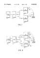
- FIG. 1shows an RF repeater arrangement comprising a pair of RF repeaters connected to a common RASP;
- FIG. 2shows a modification of the RF repeater arrangement of FIG. 1, in which two RF repeaters, each employing a pair of antennas with diversity selection are connected to the RASP and the base station;
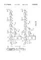
- FIG. 3shows a circuit diagram of the RASP of FIGS. 1 and 2;
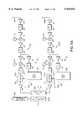
- FIG. 4shows a block diagram of one of the RF repeaters of FIG. 1;
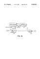
- FIG. 5shows a block diagram of one of the RF repeaters of FIG. 2;
- FIG. 5Ashows a modification of the RF repeater of FIG. 5
- FIG. 6shows a block diagram of a modification of the RF repeater of FIG. 5A
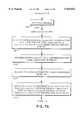
- FIGS. 7A and 7Bshows a flow chart of the program of a microprocessor forming part of the apparatuses of FIGS. 4 through 5A;
- FIG. 8shows a block diagram of another RF repeater arrangement
- FIG. 9shows a block diagram of one of the components of the arrangement of FIG. 8.
- FIG. 10shows a block diagram of part of the component of FIG. 9.
- a base station 10for connection to a public switched telephone network (not shown).
- the base station 10is a commercially available base station and is therefore not described in detail herein.
- the base station 10is connected through a RASP 12 and a coaxial cable 14 forming part of a CATV plant to a RF repeater 16.
- the cable 14is connected through a further cable 18 to a second RF repeater 20.
- FIG. 2shows a modification of the arrangement of FIG. 1.
- the RF repeaters 16 and 20 of FIG. 1which are each single antenna RADs, have been replaced by RF repeaters 16A and 20A which, as described in greater detail below, are each dual-antenna RADs.
- the base station 10 of FIG. 1has in this case been replaced by another commercially available base station 10A which is capable, in known manner, of effecting diversity selection of two receive signals, for the purpose described below.
- the RASP 12receives transmit signals broadcast from the base station 10 or 10A at a first frequency F1, and, as shown in FIG. 3, includes an attenuator 15 for attenuating the signals and a mixer 17 and an oscillator 19 which frequency-convert these transmit signals to a second, intermediate frequency F2.
- the mixer 17is followed by an amplifier 21, a bandpass filter 23 and a further amplifier 25 for amplifying and filtering the transmit signals, which are then frequency-converted by a further mixer 27 and an oscillator 29 to a third frequency F3.
- the transmit signalsare then further filtered by a bandpass filter 39 and amplified by an amplifier 41 before passing through a diplexor to the downstream CATV plant comprising the cables 14 and 18 and to the RF repeaters 16 and 20 or 16A and 20A.
- the frequency F3is selected to be suitable for transmission over the CATV plant.
- the transmit signalsare modulated and broadcast as radio signals to the handset 22.
- the radio signals transmitted by the handset 22are received and redemodulated by the RF repeaters and supplied through the CATV plant to the diplexor 45 of the RASP 12.
- the RASP 12has two upstream or return signal paths, which are indicated generally by reference numerals 47A and 47B, respectively, for processing the receive signals from the respective RF repeaters 16 and 20 or 16A and 20A.
- the signal paths 47A and 47Bare similar to one another and only one of them, therefore, will be described in greater detail.
- the signal path 47Ahas an amplifier 48a and a bandpass filter 49a for amplifying and filtering the respective receive signal, followed by a mixer 50a with an oscillator 51a for frequency-converting the receive signal from the frequency F3 to the intermediate frequency F2.
- the mixer 53is followed by a pair of amplifiers 52a and 53a and a further bandpass filter 54a for amplifying and filtering the intermediate frequency receive signal, which is then frequency-converted by a further mixer 55a and an oscillator 56a to the frequency F1.
- the receive signalis supplied from the RASP 12 to the base station 10.
- An oscillator 58aprovides a reference frequency to the diplexor 45.
- the RF repeater 16is illustrated in greater detail in FIG. 4. Since the RF repeater 20 is identical to the RF repeater 16, the RF repeater 20 is not illustrated or described herein in detail, and it is accordingly to be understood that the following description of the RF repeater 16 also applies to the RF repeater 20.
- the RF repeater 16has a diplexor 24 for connecting the cable 14 to a transmit or downstream signal path indicated generally by reference numeral 26 and to a receive signal or upstream path indicated generally by reference numeral 28.
- the transmit signal path 26includes RF amplifiers 30 through 35, bandpass filters 36 through 38 and mixers 39 and 40, with oscillators in the form of phase locked loop synthesizers 42 and 43 connected to the mixers 39 and 40, for supplying modulated transmit signals to antenna 44 in a manner which will be familiar to those skilled in the art.
- the output of the bandpass filter 37is connected to a transmit signal timing detector indicated generally by reference numeral 46, which comprises an amplifier 48, a SAW filter 50, an RF diode detector 52 and a comparator 54.
- the transmit signal timing detector 46taps off a small portion of the transmit signal from the transmit signal path 26, which is then amplified by the amplifier 48 and passed through the diode detector 52 to determine the envelope of the signal. The output of the signal timing detector 46 is then provided as receive signal timing information to a microprocessor 56, the function of which is described in greater detail below.
- the receive signal path 28has amplifiers 60 through 64, bandpass filters 65 and 66, a low pass filter 67 and mixers 68 and 69, with oscillators in the form of phase locked loop synthesizers 70 and 71 connected to the mixers 68 and 69.
- the receive signal channel 28serves to amplify, filter and demodulate receive signals received by the antenna 44 from the mobile handset 22.
- the receive signal path 28includes a signal level detector indicated generally by reference numeral 74, which comprises an RF amplifier 76, a SAW filter 78 and a fast relative signal strength indicator circuit (RSSI) 80.
- the signal level detector 74provides, at an output conductor 82 of the relative signal strength indicator circuit 80, signal level information representing the signal level of the receive signals, and this signal level information is supplied to the microprocessor 56.
- An attenuator 75is connected between the filter 67 and the amplifier 64 for attenuating the receive signal as described below in the present embodiment of the invention, but may be replaced by a squelch circuit shown in broken lines and indicated by reference numeral 75A.
- FIG. 5shows in greater detail the RF repeater 16A of FIG. 2. Since the RF repeater 20A is similar in construction and operation to the RF repeater 16A, the RF repeater 20A is not illustrated and described in detail herein and, accordingly, it is to be understood that the following description of the RF repeater 16A also applies to the RF repeater 20A.
- the RF repeater 16Ahas a transmit signal path 26A which is similar to the transmit signal path 26 of FIG. 4 and which, therefore, will not be described herein in greater detail. Also, the RF repeater 16A of FIG. 5 has a first receive signal path indicated generally by reference numeral 28A and a second receive signal path indicated generally by reference numeral 28B, which are each similar to the receive signal path 28 of FIG. 4 and the components of which have been identified by the same reference numerals as those employed in the signal path 28 and, therefore, will not be described in further detail herein.
- the first and second receive signal paths 28A and 28Bare each connected at one end thereof to a respective one of the antennas 44A, 44B and, at an opposite end thereof, to a diplexer 24A.
- the relative signal strength indicator circuit 80is connected to the microprocessor 56, which is also connected to the respective attenuator 75.
- the receive signals on the two receive signal paths 28A and 28Bare attenuated, if necessary, by the attenuators 75 and are supplied to the diplexer 24A at two different frequencies determined by the two phase locked loop synthesizers, to the cable 14.
- the commercially available base station 10Awhich has separate inputs for the two receive signals and which is capable in known manner of effecting diversity selection of one of the two receive signals, then processes the selected receive signal for connection to the public switched telephone network.
- the attenuators 75 of FIGS. 4 and 5may be replaced by the squelch circuits 75A for squelching any receive signal which is found to be below a predetermined signal level.
- FIG. 5Ashows a modification of the RF repeater 16A of FIG. 5, which effects diversity selection of the two receive signals within the RF repeater and, thus, effects diversity selection of the two radio signals received by the antennas 44A and 44B before connecting the selected receive signal to the cable 14.
- the first and second receive signal paths 28A and 28Bare each connected to an RF switch 90, which has an input connected by a conductor 91 to the microprocessor 56.
- the RF switch 90Under the control of the microprocessor 56, and in accordance with the outputs of the signal level detectors 74 of two receive signal paths 28A and 26B, the RF switch 90 connects that one of the receive signal paths 28A and 28B which has the strongest signal level to a duplexor 24A, which in turn is connected to the CATV plant.
- the spatial diversity obtained by spacing apart the two antennas 44A and 44Bis in this way employed to counteract the effect of path fading which could occur with the use of a single antenna.
- the RF repeater of FIG. 5can therefore be employed, by locating the antennas 44A and 44B an optimum distance apart from one another, to extend the reception coverage of the RF repeater, without any need to pass both of the receive signals, i.e. the receive signals from both of the antennas 44A and 44B, through the CATV plant to the base station 10. In this way, diversity selection is employed at the RF repeater to select the best of the two radio receive signals received by the antennas 44A and 44B.
- FIG. 6shows a modification of the RF repeater of FIG. 5A, in which a path selector 92, which has an input 93 connected to the microprocessor 56 (FIG. 3) and which is controlled by the microprocessor 56, is connected to the receive signal paths 28A and 28B intermediate the input and output ends thereof.
- a path selector 92which has an input 93 connected to the microprocessor 56 (FIG. 3) and which is controlled by the microprocessor 56, is connected to the receive signal paths 28A and 28B intermediate the input and output ends thereof.
- the path selector 92connects the input end of the receive signal path 28A to the output end thereof, and the input end of the receive signal path 28B to the output end thereof.
- the path selector 92connects the input end of the receive signal path 28A to the output ends of both receive signal paths 28A and 28B, and disconnects the input end of the receive signal path 28B. This allows the signal received by antenna 44A, if found to be better than that received by antenna 44B, to be output from both receive signal paths 28A and 28B, under the control of the microprocessor 36.
- the path selector 92connects the input end of the receive signal path 28B to the output ends of both receive signal paths 28A and 28B.
- the path selector 92connects the input end of the receive signal path 28A to the output end of the receive signal path 28B, and vice versa, thus allowing the two paths to be switched for test and reference purposes.
- An age timer interruptobtained as described below, then causes the output of the RSSI 80 to be taken as a measure of the signal for the current timeslot of the next occurring channel timeslot (8 timeslots away or N+8).
- step 102the phase and frequency of the downstream timeslot, i.e. the timeslot of the transmit signal, is sampled for use later in step 107.
- step 103the upstream or receive signal phase is sampled, again for use later is sep 107.
- step 104the level and switch settings calculated 7 timeslots ago (N-7), which are to be used for the next timeslot (N+1), are then output to a register, but not loaded yet.
- step 105the time at which the register (from 104) will be loaded is output. This will occur at the start of the N+1 timeslot.
- the age and squelch settings for the next arrival of the channel timeslot (8 timeslots away, or N+8)are determined at step 106.
- step 107calculates the phase/frequency adjustment of the downstream timing, and adjusts the age interrupt phase/frequency accordingly.
- step 108the program advances to the next timeslot and sets up the age timer interrupts, then waits for the next age timer interrupt.
- FIG. 8shows another RF repeater arrangement according to the present invention.
- a bi-directional amplifier 120which is connected to a RASP (not shown) by a CATV plant, which in the present embodiment is represented by a coaxial cable 122.
- the amplifier 120is connected through a coaxial cable 124 to a time slotted squelch circuit (TSS) 126, which in turn is connected by cable 128 to a further bi-directional amplifier 130 serving one or more RADS (not shown).
- TSStime slotted squelch circuit
- the bi-directional amplifier 130which serves to amplify transmit signals passing through the cable 128 to the RAD or RADS, and also to amplify the receive signal from the latter in the upstream path, adds noise in both directions at all frequencies, including those occupied by the RAD upstream or receive signal path.
- the purpose of the time slotted squelch circuit 126is to squelch a frequency band in the upstream path on the cable 128 when there is no receive signal in that frequency band, as described in greater detail below.
- the amplifier 120is also shown as being connected by co-axial cable 132 through a coupler 134 to a RAD 136 and through a time slotted squelch (TSS) 138 to a RAD 140 and a bidirectional amplifier 142, which in turn is connected to one or more further RADs.
- TSStime slotted squelch
- the purpose of the time slotted squelch 138is to squelch a predetermined frequency band in the upstream or receive signal channel of the cable 136 when no receive signal is passing through the cable 132 and, thus, to prevent noise which would otherwise be produced by the amplifier 142 on the upstream signal channel.
- the squelch frequency band of the time slotted squelch circuit 126is selected so that all upstream signals required on the cable 128 which are for the CATV plant are passed through the cable 124 to the cable 122 except those in the frequency band employed for the upstream or receive signal channel, so that the noise introduced by the amplifier 130 in this frequency band is eliminated from the cable 122 and, thus, from the RASP (not shown), when no receive signal is present on the cable 128.
- the time slotted squelch 138eliminates noise in the preselected frequency band to the right of the time slotted squelch 138, as viewed in FIG. 8, when no receive signal is present on the cable 132. However, when a receive signal is passing from the amplifier 142 towards the amplifier 120, the squelching of this selected frequency band by the time slotted squelch 138 is interrupted so that the receive signal, and the accompanying noise, will be passed through to the RASP.
- the squelching of the predetermined frequency bandserves to squelch noise in the selected frequency band in any part of the cable plant that is not carrying a receive signal.
- FIG. 9shows in greater detail the time slotted squelch 126, and since the time slotted squelch 138 is similar to the time slotted squelch 126, it is to be understood that the following description of FIG. 9 also applies to the time slotted squelch 138.
- the cable 124is connected through a high-pass filter 150 to the cable 128 for passing the transmit signal through the time slotted squelch 126 in the downstream direction.
- a transmit timing recovery circuit 152which is similar to the transmit signal timing detector 46 of FIG. 4, taps off a small portion of the transmit signal for the purpose of transmit timing recovery, as described above. This transmit timing information is made available to all channelized receiver portions in the time slotted squelch 126 to enable time slotted squelching to be effected.
- Two additional bandpass filters 154 and 156allow frequencies which are not in the upstream frequency band of the receive signal to pass through the time slotted squelch 126 without being attenuated.
- the time slotted squelch 126also incorporates a plurality of channelized time slotted squelch circuits 158a, 158b . . . 158n for controlling the passage of receive signals in corresponding frequency bands, and the squelching of these frequency bands if required by the presence of a RAD upstream signal.
- FIG. 10shows in greater detail one of the channelized time slotted squelch circuits 158a-n of FIG. 9.
- a filter 160filters the frequencies and the respective selected frequency band, which are connected to a squelch switch 162, the output of which is connected to the upstream cable 124.
- a relative signal strength indicator and level detector circuit 164provides signal level information, representing the level of the signal through the filter 160 to a microprocessor 166, to which the transmit timing from the transmit timing recovery circuit 152 is also supplied and which has an output 168 for controlling the operation of the squelch switch 162.
Landscapes
- Engineering & Computer Science (AREA)
- Computer Networks & Wireless Communication (AREA)
- Signal Processing (AREA)
- Mobile Radio Communication Systems (AREA)
- Radio Relay Systems (AREA)
Abstract
Description
Claims (14)
Applications Claiming Priority (2)
| Application Number | Priority Date | Filing Date | Title |
|---|---|---|---|
| CA002158386ACA2158386A1 (en) | 1995-09-15 | 1995-09-15 | Rf repeaters for tdma mobile telephone systems |
| CA2158386 | 1995-09-15 |
Publications (1)
| Publication Number | Publication Date |
|---|---|
| US5924022Atrue US5924022A (en) | 1999-07-13 |
Family
ID=4156602
Family Applications (1)
| Application Number | Title | Priority Date | Filing Date |
|---|---|---|---|
| US08/573,817Expired - LifetimeUS5924022A (en) | 1995-09-15 | 1995-12-18 | RF repeater for TDMA mobile telephone systems |
Country Status (2)
| Country | Link |
|---|---|
| US (1) | US5924022A (en) |
| CA (1) | CA2158386A1 (en) |
Cited By (31)
| Publication number | Priority date | Publication date | Assignee | Title |
|---|---|---|---|---|
| WO2000031896A1 (en)* | 1998-11-24 | 2000-06-02 | Airnet Communications Corporation | Tdma in-bandtranslator having delay in multiple paths to allow for selective diversity and automatic level control |
| US6173190B1 (en)* | 1996-12-19 | 2001-01-09 | Sony Corporation | Signal receiving apparatus and method |
| US6259910B1 (en)* | 1998-02-13 | 2001-07-10 | Lucent Technologies, Inc. | Wireless telecommunications system architecture supporting block radio technology |
| WO2001078255A1 (en)* | 2000-04-11 | 2001-10-18 | Airnet Communications Corporation | Method and apparatus employing delay combining for receive diversity in a wireless system repeater |
| US6353729B1 (en)* | 1997-11-14 | 2002-03-05 | Nortel Networks Limited | Using an RF repeater in CDMA applications to combat interference caused by a non-collocated radio |
| US6373833B1 (en)* | 1996-07-25 | 2002-04-16 | Nokia Telecommunications Oy | Cell expansion in a time division cellular system using frequency converting repeaters |
| WO2003023999A1 (en)* | 2001-08-31 | 2003-03-20 | Linkair Communications, Inc. | A method of error-correcting encoding source data elements and corresponding iterative decoder |
| US6560895B1 (en) | 2001-12-10 | 2003-05-13 | Willard Clark | Chicken manure processing apparatus |
| WO2003058848A1 (en)* | 2001-12-26 | 2003-07-17 | Celletra Ltd | Modular base station antenna control system |
| US6690657B1 (en) | 2000-02-25 | 2004-02-10 | Berkeley Concept Research Corporation | Multichannel distributed wireless repeater network |
| US6766592B1 (en) | 2001-12-10 | 2004-07-27 | Willard Clark | Chicken manure processing apparatus |
| US6961366B1 (en)* | 2001-01-02 | 2005-11-01 | Applied Micro Circuits Corporation | System and method for redundant path connections in digital communications network |
| US20050250442A1 (en)* | 2002-07-10 | 2005-11-10 | Renaud Dore | Radio communication repeater |
| US20060270412A1 (en)* | 2005-05-25 | 2006-11-30 | Willins Bruce A | System and method for resilient coverage in a wireless environment |
| US20070008939A1 (en)* | 2005-06-10 | 2007-01-11 | Adc Telecommunications, Inc. | Providing wireless coverage into substantially closed environments |
| US20070263852A1 (en)* | 2006-04-18 | 2007-11-15 | 2Wire, Inc. | Method and apparatus for providing power to a network interface device via telephone lines |
| US20080165694A1 (en)* | 2007-01-10 | 2008-07-10 | Dell Products, Lp | Interconnect Circuit, System, and Method for Providing Operating Modes for Communication Channels |
| US20080175212A1 (en)* | 2006-04-18 | 2008-07-24 | Richard Barry Angell | Remote antenna system |
| US20090316609A1 (en)* | 2008-06-24 | 2009-12-24 | Lgc Wireless, Inc. | System and method for synchronized time-division duplex signal switching |
| US8462683B2 (en) | 2011-01-12 | 2013-06-11 | Adc Telecommunications, Inc. | Distinct transport path for MIMO transmissions in distributed antenna systems |
| US8472579B2 (en) | 2010-07-28 | 2013-06-25 | Adc Telecommunications, Inc. | Distributed digital reference clock |
| US8532242B2 (en) | 2010-10-27 | 2013-09-10 | Adc Telecommunications, Inc. | Distributed antenna system with combination of both all digital transport and hybrid digital/analog transport |
| US8693342B2 (en) | 2011-10-28 | 2014-04-08 | Adc Telecommunications, Inc. | Distributed antenna system using time division duplexing scheme |
| US20150011208A1 (en)* | 2013-07-03 | 2015-01-08 | Wireless Extenders, Inc. | Remote control application for wireless booster |
| US20150200722A1 (en)* | 2012-06-07 | 2015-07-16 | Lg Electronics Inc. | Method and apparatus for transmitting uplink signal in wireless communication system |
| US9178636B2 (en) | 2013-02-22 | 2015-11-03 | Adc Telecommunications, Inc. | Universal remote radio head |
| US20160037188A1 (en)* | 2011-06-27 | 2016-02-04 | Trilithic, Inc. | Apparatus for detecting leakage in digitally modulated systems |
| US9596322B2 (en) | 2014-06-11 | 2017-03-14 | Commscope Technologies Llc | Bitrate efficient transport through distributed antenna systems |
| US9787457B2 (en) | 2013-10-07 | 2017-10-10 | Commscope Technologies Llc | Systems and methods for integrating asynchronous signals in distributed antenna system with direct digital interface to base station |
| US10020850B2 (en) | 2013-02-22 | 2018-07-10 | Commscope Technologies Llc | Master reference for base station network interface sourced from distributed antenna system |
| US10499269B2 (en) | 2015-11-12 | 2019-12-03 | Commscope Technologies Llc | Systems and methods for assigning controlled nodes to channel interfaces of a controller |
Citations (9)
| Publication number | Priority date | Publication date | Assignee | Title |
|---|---|---|---|---|
| US4704734A (en)* | 1986-02-18 | 1987-11-03 | Motorola, Inc. | Method and apparatus for signal strength measurement and antenna selection in cellular radiotelephone systems |
| US4713809A (en)* | 1985-07-25 | 1987-12-15 | Nec Corporation | Time division multiple access radio communications system |
| US4742530A (en)* | 1983-11-11 | 1988-05-03 | Fujitsu Limited | Radio relay method and its apparatus for digital communication |
| US5200955A (en)* | 1988-04-22 | 1993-04-06 | British Telecommunications Public Limited Company | Repeater for tdma mobile radio |
| CA2058737A1 (en)* | 1992-01-03 | 1993-07-04 | Andrew S. Beasley | Rf repeater arrangement with improved frequency reuse for wireless telephones |
| US5321736A (en)* | 1992-01-03 | 1994-06-14 | Pcs Microcell International Inc. | Distributed RF repeater arrangement for cordless telephones |
| US5521904A (en)* | 1993-12-07 | 1996-05-28 | Telefonaktiebolaget Lm Ericsson | Method and apparatus for testing a base station in a time division multiple access radio communications system |
| US5602555A (en)* | 1993-08-12 | 1997-02-11 | Northern Telecom Limited | Base station antenna arrangement |
| US5701579A (en)* | 1993-11-29 | 1997-12-23 | Pcs Solutions, Llc | Modular antenna driver including removable modules each characteristic of a handset type |
- 1995
- 1995-09-15CACA002158386Apatent/CA2158386A1/ennot_activeAbandoned
- 1995-12-18USUS08/573,817patent/US5924022A/ennot_activeExpired - Lifetime
Patent Citations (9)
| Publication number | Priority date | Publication date | Assignee | Title |
|---|---|---|---|---|
| US4742530A (en)* | 1983-11-11 | 1988-05-03 | Fujitsu Limited | Radio relay method and its apparatus for digital communication |
| US4713809A (en)* | 1985-07-25 | 1987-12-15 | Nec Corporation | Time division multiple access radio communications system |
| US4704734A (en)* | 1986-02-18 | 1987-11-03 | Motorola, Inc. | Method and apparatus for signal strength measurement and antenna selection in cellular radiotelephone systems |
| US5200955A (en)* | 1988-04-22 | 1993-04-06 | British Telecommunications Public Limited Company | Repeater for tdma mobile radio |
| CA2058737A1 (en)* | 1992-01-03 | 1993-07-04 | Andrew S. Beasley | Rf repeater arrangement with improved frequency reuse for wireless telephones |
| US5321736A (en)* | 1992-01-03 | 1994-06-14 | Pcs Microcell International Inc. | Distributed RF repeater arrangement for cordless telephones |
| US5602555A (en)* | 1993-08-12 | 1997-02-11 | Northern Telecom Limited | Base station antenna arrangement |
| US5701579A (en)* | 1993-11-29 | 1997-12-23 | Pcs Solutions, Llc | Modular antenna driver including removable modules each characteristic of a handset type |
| US5521904A (en)* | 1993-12-07 | 1996-05-28 | Telefonaktiebolaget Lm Ericsson | Method and apparatus for testing a base station in a time division multiple access radio communications system |
Cited By (63)
| Publication number | Priority date | Publication date | Assignee | Title |
|---|---|---|---|---|
| US6373833B1 (en)* | 1996-07-25 | 2002-04-16 | Nokia Telecommunications Oy | Cell expansion in a time division cellular system using frequency converting repeaters |
| US6173190B1 (en)* | 1996-12-19 | 2001-01-09 | Sony Corporation | Signal receiving apparatus and method |
| US6353729B1 (en)* | 1997-11-14 | 2002-03-05 | Nortel Networks Limited | Using an RF repeater in CDMA applications to combat interference caused by a non-collocated radio |
| US6259910B1 (en)* | 1998-02-13 | 2001-07-10 | Lucent Technologies, Inc. | Wireless telecommunications system architecture supporting block radio technology |
| WO2000031896A1 (en)* | 1998-11-24 | 2000-06-02 | Airnet Communications Corporation | Tdma in-bandtranslator having delay in multiple paths to allow for selective diversity and automatic level control |
| US6088570A (en)* | 1998-11-24 | 2000-07-11 | Airnet Communications Corporation | Method and apparatus employing delay elements in multiple diversity paths of a wireless system repeater translator to allow for selective diversity and automatic level control in a time-division multiple access system |
| US6690657B1 (en) | 2000-02-25 | 2004-02-10 | Berkeley Concept Research Corporation | Multichannel distributed wireless repeater network |
| WO2001078255A1 (en)* | 2000-04-11 | 2001-10-18 | Airnet Communications Corporation | Method and apparatus employing delay combining for receive diversity in a wireless system repeater |
| US6961366B1 (en)* | 2001-01-02 | 2005-11-01 | Applied Micro Circuits Corporation | System and method for redundant path connections in digital communications network |
| WO2003023999A1 (en)* | 2001-08-31 | 2003-03-20 | Linkair Communications, Inc. | A method of error-correcting encoding source data elements and corresponding iterative decoder |
| US6560895B1 (en) | 2001-12-10 | 2003-05-13 | Willard Clark | Chicken manure processing apparatus |
| US6766592B1 (en) | 2001-12-10 | 2004-07-27 | Willard Clark | Chicken manure processing apparatus |
| WO2003058848A1 (en)* | 2001-12-26 | 2003-07-17 | Celletra Ltd | Modular base station antenna control system |
| US20050085267A1 (en)* | 2001-12-26 | 2005-04-21 | Paul Lemson | Modular base station antenna control system |
| US20050250442A1 (en)* | 2002-07-10 | 2005-11-10 | Renaud Dore | Radio communication repeater |
| CN100411320C (en)* | 2002-07-10 | 2008-08-13 | 汤姆森许可贸易公司 | radio communication repeater |
| US7310497B2 (en)* | 2002-07-10 | 2007-12-18 | Thomson Licensing | Radio communication repeater |
| US20060270412A1 (en)* | 2005-05-25 | 2006-11-30 | Willins Bruce A | System and method for resilient coverage in a wireless environment |
| US20070008939A1 (en)* | 2005-06-10 | 2007-01-11 | Adc Telecommunications, Inc. | Providing wireless coverage into substantially closed environments |
| US20100215028A1 (en)* | 2005-06-10 | 2010-08-26 | Adc Telecommunications, Inc. | Providing wireless coverage into substantially closed environments |
| US20110228867A1 (en)* | 2006-04-18 | 2011-09-22 | Richard Barry Angell | Remote antenna system |
| US20080175212A1 (en)* | 2006-04-18 | 2008-07-24 | Richard Barry Angell | Remote antenna system |
| US7965977B2 (en)* | 2006-04-18 | 2011-06-21 | 2Wire, Inc. | Remote antenna system |
| US20070263852A1 (en)* | 2006-04-18 | 2007-11-15 | 2Wire, Inc. | Method and apparatus for providing power to a network interface device via telephone lines |
| US8238821B2 (en)* | 2006-04-18 | 2012-08-07 | 2Wire, Inc. | Remote antenna system |
| US8520835B2 (en) | 2006-04-18 | 2013-08-27 | 2Wire, Inc. | Method and apparatus for providing power to a network interface device via telephone lines |
| US7764627B2 (en)* | 2007-01-10 | 2010-07-27 | Dell Products, Lp | Interconnect circuit, system, and method for providing operating modes for communication channels |
| US20080165694A1 (en)* | 2007-01-10 | 2008-07-10 | Dell Products, Lp | Interconnect Circuit, System, and Method for Providing Operating Modes for Communication Channels |
| US20090316609A1 (en)* | 2008-06-24 | 2009-12-24 | Lgc Wireless, Inc. | System and method for synchronized time-division duplex signal switching |
| US8310963B2 (en) | 2008-06-24 | 2012-11-13 | Adc Telecommunications, Inc. | System and method for synchronized time-division duplex signal switching |
| US8472579B2 (en) | 2010-07-28 | 2013-06-25 | Adc Telecommunications, Inc. | Distributed digital reference clock |
| US8837659B2 (en) | 2010-07-28 | 2014-09-16 | Adc Telecommunications, Inc. | Distributed digital reference clock |
| USRE48351E1 (en) | 2010-07-28 | 2020-12-08 | Commscope Technologies Llc | Distributed digital reference clock |
| USRE48342E1 (en) | 2010-07-28 | 2020-12-01 | Commscope Technologies Llc | Distributed digital reference clock |
| US8532242B2 (en) | 2010-10-27 | 2013-09-10 | Adc Telecommunications, Inc. | Distributed antenna system with combination of both all digital transport and hybrid digital/analog transport |
| USRE48757E1 (en) | 2010-10-27 | 2021-09-28 | Commscope Technologies Llc | Distributed antenna system with combination of both all digital transport and hybrid digital/analog transport |
| USRE47160E1 (en) | 2010-10-27 | 2018-12-11 | Commscope Technologies Llc | Distributed antenna system with combination of both all digital transport and hybrid digital/analog transport |
| US8743756B2 (en) | 2011-01-12 | 2014-06-03 | Adc Telecommunications, Inc. | Distinct transport path for MIMO transmissions in distributed antenna systems |
| US8462683B2 (en) | 2011-01-12 | 2013-06-11 | Adc Telecommunications, Inc. | Distinct transport path for MIMO transmissions in distributed antenna systems |
| US9877050B2 (en)* | 2011-06-27 | 2018-01-23 | Trilithic, Inc. | Apparatus for detecting leakage in digitally modulated systems |
| US10334291B2 (en) | 2011-06-27 | 2019-06-25 | Viavi Solutions, Inc. | Apparatus for detecting leakage in digitally modulated systems |
| US20160037188A1 (en)* | 2011-06-27 | 2016-02-04 | Trilithic, Inc. | Apparatus for detecting leakage in digitally modulated systems |
| US9219520B2 (en) | 2011-10-28 | 2015-12-22 | Adc Telecommunications, Inc. | Distributed antenna system using time division duplexing scheme |
| US8693342B2 (en) | 2011-10-28 | 2014-04-08 | Adc Telecommunications, Inc. | Distributed antenna system using time division duplexing scheme |
| US20150200722A1 (en)* | 2012-06-07 | 2015-07-16 | Lg Electronics Inc. | Method and apparatus for transmitting uplink signal in wireless communication system |
| US9584211B2 (en)* | 2012-06-07 | 2017-02-28 | Lg Electronics Inc. | Method and apparatus for transmitting uplink signal in wireless communication system |
| US10567044B2 (en) | 2013-02-22 | 2020-02-18 | Commscope Technologies Llc | Universal remote radio head |
| US11329701B2 (en) | 2013-02-22 | 2022-05-10 | Commscope Technologies Llc | Master reference for base station network interface sourced from distributed antenna system |
| US9504039B2 (en) | 2013-02-22 | 2016-11-22 | Commscope Technologies Llc | Universal remote radio head |
| US10855338B2 (en) | 2013-02-22 | 2020-12-01 | Commscope Technologies Llc | Master reference for base station network interface sourced from distributed antenna system |
| US10020850B2 (en) | 2013-02-22 | 2018-07-10 | Commscope Technologies Llc | Master reference for base station network interface sourced from distributed antenna system |
| US10128918B2 (en) | 2013-02-22 | 2018-11-13 | Commscope Technologies Llc | Universal remote radio head |
| US9178636B2 (en) | 2013-02-22 | 2015-11-03 | Adc Telecommunications, Inc. | Universal remote radio head |
| US20150011208A1 (en)* | 2013-07-03 | 2015-01-08 | Wireless Extenders, Inc. | Remote control application for wireless booster |
| US9408016B2 (en)* | 2013-07-03 | 2016-08-02 | Wilson Electronics, Llc | Remote control application for wireless booster |
| US10205584B2 (en) | 2013-10-07 | 2019-02-12 | Commscope Technologies Llc | Systems and methods for integrating asynchronous signals in distributed antenna system with direct digital interface to base station |
| US9787457B2 (en) | 2013-10-07 | 2017-10-10 | Commscope Technologies Llc | Systems and methods for integrating asynchronous signals in distributed antenna system with direct digital interface to base station |
| US10333591B2 (en) | 2014-06-11 | 2019-06-25 | Commscope Technologies Llc | Bitrate efficient transport through distributed antenna systems |
| US10020851B2 (en) | 2014-06-11 | 2018-07-10 | Commscope Technologies Llc | Bitrate efficient transport through distributed antenna systems |
| US9954584B2 (en) | 2014-06-11 | 2018-04-24 | Commscope Technologies Llc | Bitrate efficient transport through distributed antenna systems |
| US9686379B2 (en) | 2014-06-11 | 2017-06-20 | Commscope Technologies Llc | Bitrate efficient transport through distributed antenna systems |
| US9596322B2 (en) | 2014-06-11 | 2017-03-14 | Commscope Technologies Llc | Bitrate efficient transport through distributed antenna systems |
| US10499269B2 (en) | 2015-11-12 | 2019-12-03 | Commscope Technologies Llc | Systems and methods for assigning controlled nodes to channel interfaces of a controller |
Also Published As
| Publication number | Publication date |
|---|---|
| CA2158386A1 (en) | 1997-03-16 |
Similar Documents
| Publication | Publication Date | Title |
|---|---|---|
| US5924022A (en) | RF repeater for TDMA mobile telephone systems | |
| US5918154A (en) | Communications systems employing antenna diversity | |
| US6480702B1 (en) | Apparatus and method for distributing wireless communications signals to remote cellular antennas | |
| US6032057A (en) | Cellular radio system repeater and base station | |
| EP1109332A2 (en) | A digital repeater | |
| SE507442C3 (en) | Hoegfrekvenssignal-foerstaerkare | |
| CA2054361A1 (en) | Cellular telephone service using spread spectrum transmission | |
| SK106596A3 (en) | Method and apparatus for mitigating interference in a communication system | |
| KR102296380B1 (en) | A detection system for dual band inputt-output signal in 5g milimeter wave bandwidth | |
| US20060286940A1 (en) | Array antenna transmission/receiver | |
| US9100082B2 (en) | Radio communication system and a repeater | |
| EP0128812A2 (en) | Space-diversity receiving system | |
| JP3621239B2 (en) | Wireless repeater amplifier | |
| CA2069462A1 (en) | Rf repeater arrangement with reduced noise for wireless telephones | |
| JP4516044B2 (en) | Receiving system | |
| JP2784147B2 (en) | Antenna shared circuit | |
| US6836648B1 (en) | Receiving apparatus for electromagnetic signals | |
| KR100544227B1 (en) | Transmission feedback signal removing device and relay system using same | |
| KR100302944B1 (en) | Repeater using frequency change | |
| JPH07235894A (en) | Eliminating device for disturbing wave in radio communication equipment | |
| KR20010050670A (en) | Method and apparatus for power based dynamic channel allocation for receiver dynamic range mitigation | |
| KR101118670B1 (en) | Apparatus and method for detectting received signal in tdd system | |
| KR200199765Y1 (en) | Channel selector for wireless repeater having gain adjusting funcution, and channel selecting type wireless repeater using the same | |
| KR101007394B1 (en) | Receiver in Frequency Division Duplex System | |
| KR100500876B1 (en) | Interference signal cancellation system and relay system therefor |
Legal Events
| Date | Code | Title | Description |
|---|---|---|---|
| STCF | Information on status: patent grant | Free format text:PATENTED CASE | |
| CC | Certificate of correction | ||
| AS | Assignment | Owner name:KEYBANK NATIONAL ASSOCIATION, OHIO Free format text:SECURITY AGREEMENT;ASSIGNOR:ALLEN TELECOM, INC.;REEL/FRAME:015017/0844 Effective date:20020131 | |
| AS | Assignment | Owner name:KEYBANK NATIONAL ASSOCIATION, OHIO Free format text:SECURITY INTEREST;ASSIGNOR:ALLEN TELECOM, INC.;REEL/FRAME:012822/0425 Effective date:20020131 | |
| FPAY | Fee payment | Year of fee payment:4 | |
| SULP | Surcharge for late payment | ||
| REMI | Maintenance fee reminder mailed | ||
| AS | Assignment | Owner name:ALLEN TELECOM INC., OHIO Free format text:RELEASE OF SECURITY INTEREST;ASSIGNOR:KEYBANK NATIONAL ASSOCIATION, AS COLLATERAL AGENT;REEL/FRAME:015027/0518 Effective date:20030716 | |
| FPAY | Fee payment | Year of fee payment:8 | |
| FPAY | Fee payment | Year of fee payment:12 | |
| AS | Assignment | Owner name:JPMORGAN CHASE BANK, N.A., AS COLLATERAL AGENT, NE Free format text:SECURITY AGREEMENT;ASSIGNORS:ALLEN TELECOM LLC, A DELAWARE LLC;ANDREW LLC, A DELAWARE LLC;COMMSCOPE, INC. OF NORTH CAROLINA, A NORTH CAROLINA CORPORATION;REEL/FRAME:026276/0363 Effective date:20110114 | |
| AS | Assignment | Owner name:JPMORGAN CHASE BANK, N.A., AS COLLATERAL AGENT, NE Free format text:SECURITY AGREEMENT;ASSIGNORS:ALLEN TELECOM LLC, A DELAWARE LLC;ANDREW LLC, A DELAWARE LLC;COMMSCOPE, INC OF NORTH CAROLINA, A NORTH CAROLINA CORPORATION;REEL/FRAME:026272/0543 Effective date:20110114 | |
| AS | Assignment | Owner name:WILMINGTON TRUST, NATIONAL ASSOCIATION, AS COLLATERAL AGENT, CONNECTICUT Free format text:SECURITY INTEREST;ASSIGNORS:ALLEN TELECOM LLC;COMMSCOPE TECHNOLOGIES LLC;COMMSCOPE, INC. OF NORTH CAROLINA;AND OTHERS;REEL/FRAME:036201/0283 Effective date:20150611 Owner name:WILMINGTON TRUST, NATIONAL ASSOCIATION, AS COLLATE Free format text:SECURITY INTEREST;ASSIGNORS:ALLEN TELECOM LLC;COMMSCOPE TECHNOLOGIES LLC;COMMSCOPE, INC. OF NORTH CAROLINA;AND OTHERS;REEL/FRAME:036201/0283 Effective date:20150611 | |
| AS | Assignment | Owner name:COMMSCOPE TECHNOLOGIES LLC, NORTH CAROLINA Free format text:RELEASE OF SECURITY INTEREST PATENTS (RELEASES RF 036201/0283);ASSIGNOR:WILMINGTON TRUST, NATIONAL ASSOCIATION;REEL/FRAME:042126/0434 Effective date:20170317 Owner name:REDWOOD SYSTEMS, INC., NORTH CAROLINA Free format text:RELEASE OF SECURITY INTEREST PATENTS (RELEASES RF 036201/0283);ASSIGNOR:WILMINGTON TRUST, NATIONAL ASSOCIATION;REEL/FRAME:042126/0434 Effective date:20170317 Owner name:ALLEN TELECOM LLC, NORTH CAROLINA Free format text:RELEASE OF SECURITY INTEREST PATENTS (RELEASES RF 036201/0283);ASSIGNOR:WILMINGTON TRUST, NATIONAL ASSOCIATION;REEL/FRAME:042126/0434 Effective date:20170317 Owner name:COMMSCOPE, INC. OF NORTH CAROLINA, NORTH CAROLINA Free format text:RELEASE OF SECURITY INTEREST PATENTS (RELEASES RF 036201/0283);ASSIGNOR:WILMINGTON TRUST, NATIONAL ASSOCIATION;REEL/FRAME:042126/0434 Effective date:20170317 | |
| AS | Assignment | Owner name:REDWOOD SYSTEMS, INC., NORTH CAROLINA Free format text:RELEASE BY SECURED PARTY;ASSIGNOR:JPMORGAN CHASE BANK, N.A.;REEL/FRAME:048840/0001 Effective date:20190404 Owner name:ANDREW LLC, NORTH CAROLINA Free format text:RELEASE BY SECURED PARTY;ASSIGNOR:JPMORGAN CHASE BANK, N.A.;REEL/FRAME:048840/0001 Effective date:20190404 Owner name:COMMSCOPE, INC. OF NORTH CAROLINA, NORTH CAROLINA Free format text:RELEASE BY SECURED PARTY;ASSIGNOR:JPMORGAN CHASE BANK, N.A.;REEL/FRAME:048840/0001 Effective date:20190404 Owner name:COMMSCOPE TECHNOLOGIES LLC, NORTH CAROLINA Free format text:RELEASE BY SECURED PARTY;ASSIGNOR:JPMORGAN CHASE BANK, N.A.;REEL/FRAME:048840/0001 Effective date:20190404 Owner name:ALLEN TELECOM LLC, ILLINOIS Free format text:RELEASE BY SECURED PARTY;ASSIGNOR:JPMORGAN CHASE BANK, N.A.;REEL/FRAME:048840/0001 Effective date:20190404 Owner name:COMMSCOPE TECHNOLOGIES LLC, NORTH CAROLINA Free format text:RELEASE BY SECURED PARTY;ASSIGNOR:JPMORGAN CHASE BANK, N.A.;REEL/FRAME:049260/0001 Effective date:20190404 Owner name:ALLEN TELECOM LLC, ILLINOIS Free format text:RELEASE BY SECURED PARTY;ASSIGNOR:JPMORGAN CHASE BANK, N.A.;REEL/FRAME:049260/0001 Effective date:20190404 Owner name:REDWOOD SYSTEMS, INC., NORTH CAROLINA Free format text:RELEASE BY SECURED PARTY;ASSIGNOR:JPMORGAN CHASE BANK, N.A.;REEL/FRAME:049260/0001 Effective date:20190404 Owner name:COMMSCOPE, INC. OF NORTH CAROLINA, NORTH CAROLINA Free format text:RELEASE BY SECURED PARTY;ASSIGNOR:JPMORGAN CHASE BANK, N.A.;REEL/FRAME:049260/0001 Effective date:20190404 Owner name:ANDREW LLC, NORTH CAROLINA Free format text:RELEASE BY SECURED PARTY;ASSIGNOR:JPMORGAN CHASE BANK, N.A.;REEL/FRAME:049260/0001 Effective date:20190404 |