US5923764A - Virtual electroacoustic audiometry for unaided simulated aided, and aided hearing evaluation - Google Patents
Virtual electroacoustic audiometry for unaided simulated aided, and aided hearing evaluationDownload PDFInfo
- Publication number
- US5923764A US5923764AUS08/769,186US76918696AUS5923764AUS 5923764 AUS5923764 AUS 5923764AUS 76918696 AUS76918696 AUS 76918696AUS 5923764 AUS5923764 AUS 5923764A
- Authority
- US
- United States
- Prior art keywords
- hearing aid
- acoustic
- hearing
- ear
- canal
- Prior art date
- Legal status (The legal status is an assumption and is not a legal conclusion. Google has not performed a legal analysis and makes no representation as to the accuracy of the status listed.)
- Expired - Lifetime
Links
Images


Classifications
- A—HUMAN NECESSITIES
- A61—MEDICAL OR VETERINARY SCIENCE; HYGIENE
- A61B—DIAGNOSIS; SURGERY; IDENTIFICATION
- A61B5/00—Measuring for diagnostic purposes; Identification of persons
- A61B5/68—Arrangements of detecting, measuring or recording means, e.g. sensors, in relation to patient
- A61B5/6801—Arrangements of detecting, measuring or recording means, e.g. sensors, in relation to patient specially adapted to be attached to or worn on the body surface
- A61B5/6813—Specially adapted to be attached to a specific body part
- A61B5/6814—Head
- A61B5/6815—Ear
- A61B5/6817—Ear canal
- A—HUMAN NECESSITIES
- A61—MEDICAL OR VETERINARY SCIENCE; HYGIENE
- A61B—DIAGNOSIS; SURGERY; IDENTIFICATION
- A61B5/00—Measuring for diagnostic purposes; Identification of persons
- A61B5/12—Audiometering
- A61B5/121—Audiometering evaluating hearing capacity
- A—HUMAN NECESSITIES
- A61—MEDICAL OR VETERINARY SCIENCE; HYGIENE
- A61B—DIAGNOSIS; SURGERY; IDENTIFICATION
- A61B5/00—Measuring for diagnostic purposes; Identification of persons
- A61B5/68—Arrangements of detecting, measuring or recording means, e.g. sensors, in relation to patient
- A61B5/6887—Arrangements of detecting, measuring or recording means, e.g. sensors, in relation to patient mounted on external non-worn devices, e.g. non-medical devices
- G—PHYSICS
- G16—INFORMATION AND COMMUNICATION TECHNOLOGY [ICT] SPECIALLY ADAPTED FOR SPECIFIC APPLICATION FIELDS
- G16H—HEALTHCARE INFORMATICS, i.e. INFORMATION AND COMMUNICATION TECHNOLOGY [ICT] SPECIALLY ADAPTED FOR THE HANDLING OR PROCESSING OF MEDICAL OR HEALTHCARE DATA
- G16H40/00—ICT specially adapted for the management or administration of healthcare resources or facilities; ICT specially adapted for the management or operation of medical equipment or devices
- G16H40/40—ICT specially adapted for the management or administration of healthcare resources or facilities; ICT specially adapted for the management or operation of medical equipment or devices for the management of medical equipment or devices, e.g. scheduling maintenance or upgrades
- G—PHYSICS
- G16—INFORMATION AND COMMUNICATION TECHNOLOGY [ICT] SPECIALLY ADAPTED FOR SPECIFIC APPLICATION FIELDS
- G16H—HEALTHCARE INFORMATICS, i.e. INFORMATION AND COMMUNICATION TECHNOLOGY [ICT] SPECIALLY ADAPTED FOR THE HANDLING OR PROCESSING OF MEDICAL OR HEALTHCARE DATA
- G16H50/00—ICT specially adapted for medical diagnosis, medical simulation or medical data mining; ICT specially adapted for detecting, monitoring or modelling epidemics or pandemics
- G16H50/20—ICT specially adapted for medical diagnosis, medical simulation or medical data mining; ICT specially adapted for detecting, monitoring or modelling epidemics or pandemics for computer-aided diagnosis, e.g. based on medical expert systems
- H—ELECTRICITY
- H04—ELECTRIC COMMUNICATION TECHNIQUE
- H04R—LOUDSPEAKERS, MICROPHONES, GRAMOPHONE PICK-UPS OR LIKE ACOUSTIC ELECTROMECHANICAL TRANSDUCERS; DEAF-AID SETS; PUBLIC ADDRESS SYSTEMS
- H04R25/00—Deaf-aid sets, i.e. electro-acoustic or electro-mechanical hearing aids; Electric tinnitus maskers providing an auditory perception
- H04R25/30—Monitoring or testing of hearing aids, e.g. functioning, settings, battery power
- H—ELECTRICITY
- H04—ELECTRIC COMMUNICATION TECHNIQUE
- H04R—LOUDSPEAKERS, MICROPHONES, GRAMOPHONE PICK-UPS OR LIKE ACOUSTIC ELECTROMECHANICAL TRANSDUCERS; DEAF-AID SETS; PUBLIC ADDRESS SYSTEMS
- H04R25/00—Deaf-aid sets, i.e. electro-acoustic or electro-mechanical hearing aids; Electric tinnitus maskers providing an auditory perception
- H04R25/70—Adaptation of deaf aid to hearing loss, e.g. initial electronic fitting
- H—ELECTRICITY
- H04—ELECTRIC COMMUNICATION TECHNIQUE
- H04R—LOUDSPEAKERS, MICROPHONES, GRAMOPHONE PICK-UPS OR LIKE ACOUSTIC ELECTROMECHANICAL TRANSDUCERS; DEAF-AID SETS; PUBLIC ADDRESS SYSTEMS
- H04R29/00—Monitoring arrangements; Testing arrangements
- H04R29/001—Monitoring arrangements; Testing arrangements for loudspeakers
Definitions
- the present inventionrelates to hearing evaluation and hearing aid fitting. More particularly, the present invention relates to virtual electroacoustic audiometry for unaided, simulated aided, and aided hearing evaluation.
- the human auditory systemprocesses sounds from a complex three-dimensional space via the external, middle, and inner ear, as well as via the complex neural pathways that lead to the auditory cortex within the brain.
- a measurable hearing lossdue to various conductive, sensorineural, or central auditory disorders, affects a significant percentage of the human population, particularly elderly persons.
- Rehabilitation via hearing aidsremains the only viable option for those types of hearing impairments that cannot otherwise be medically treated or surgically alleviated.
- ITEin-the-ear
- BTEbehind-the-ear
- ITCin-the-canal
- CICcompletely-in-the-canal
- the hearing aid prescription processinvolves translating the diagnostic data into target hearing aid electroacoustic parameters that are used in the selection of the hearing aid.
- Traditional hearing evaluation methods and instrumentsemploy a variety of air-conduction transducers for coupling acoustic signals into the ear.
- Commonly used transducersinclude supra-aural earphones, such as TDH-39, TDH-49, TDH-50, insert earphones, such as ER-3A, and free-field speakers (see Specification of Audiometers, ANSI-S3.6-1989, American Standards National Institute).
- a threshold measurement obtained with such transducersis referenced to a mean threshold obtained by testing a group of otologically normal individuals.
- This mean thresholdby definition, is referred to as the zero decibel hearing-level or 0 dB HL.
- threshold measurements of otologically normal personscan vary by 20 dB or more. These variations can be attributed to following factors:
- BMLD and BILDEarly studies of BMLD and BILD involved the presentation of signal and noise to one or both ears at various phase relationships. Tone detection and speech intelligibility were shown to vary as much as 15 dB, depending on the signal/noise phase relationship. Even though many of these studies suggest the significance of binaural considerations, today's hearing assessment methods, unaided and aided, primarily deal with monaural test conditions, i.e. testing one ear at a time.
- audiometric signalssuch as speech and/or noise are delivered to the ear via a conventional audiometers and associated transducers
- the sound perception by the test subjectis not localized to any particular point in space (see Specification of Audiometers, ANSI-S3.6-1989, American Standards National Institute).
- the speech stimuli levelis adjusted for one ear and speech noise level is separately adjusted in the opposite ear.
- the test subjectperceives sounds to be within the head and localization is limited to left/right direction. This type of signal presentation and perception is referred to as intracranial and is unlike the way humans normally perceive natural sounds.
- Speech intelligibility and discriminationdeteriorates in the presence of competing speech and other environmental sounds. Furthermore, the acoustic properties of a room, e.g. its walls and objects within the room, all play an important role in the filtering process subjected to the original signal source. These filtering effects are especially significant for hearing-impaired individuals who typically have a limited frequency response and dynamic range in their hearing function.
- REMreal ear measurement
- Target hearing aid characteristicsare then calculated based on the natural ear canal response characteristics, as well as other criteria (see Mueller, H. G., Hawkins, D. B., Northern, J. L., Probe Microphone Measurements: Hearing Aid Selection and Assessment, 1992, Ch. 5).
- the hearing aidis prescribed, ordered, and received during a subsequent visit, the aid is inserted over the probe tube and adjusted to match the prescribed target hearing aid characteristics.
- REM evaluation and REM-based prescriptive methodsprovide considerable improvements over previous fitting methods which relied on the combination of audiometric data and hearing aid 2-cc coupler specifications.
- REMoffers insight into the in situ performance of the hearing aid, it suffers from several fundamental problems, as described below:
- Real ear measurementsare taken with a specific stimulus type, source-ear distance/orientation, and room acoustics.
- the specific test conditionmay not represent realistic listening scenarios encountered by hearing aid users.
- a hearing aidmay be optimized for a specific listening condition while compromising the performance under other conditions that may be more important to the hearing-impaired individual.
- REM instrumentsemploy sound field speakers in a room with ambient background noise that often exceeds 50 dB SPL across standard audiometric frequencies. This necessitates stimulus levels of 60 dB or higher to produce measurements having sufficient signal-to-noise ratios. This is problematic if hearing aid performance characterization under low level acoustic stimuli is required.
- a significant factor that contributes to the results of a hearing aid fittingis the problem of adequately correlating diagnostic data with fitting needs of the hearing-impaired individual. Diagnostic measurements are typically taken in dB HL with transducers that are calibrated in 6-cc couplers. Hearing aid specification and performance measurements employ 2-cc couplers which do not represent the real-ear. Fitting involves the use of one of several prescriptive formulae, with results that are known to vary as much as 15 dB for the same diagnostic data across standard audiometric frequencies (see Mueller, H. G., Hawkins, D. B., Northern, J. L., Probe Microphone Measurements: Hearing Aid Selection and Assessment, 1992, p 107). These fitting formulae incorporate statistically based conversion factors that simplify the correlation of hearing aid requirements to a particular hearing impairment. However, averaged conversion factors are known to vary considerably with respect to objectively measured individual conversion factors.
- Hearing rehabilitation through the use of hearing aidsremains the only viable option for many hearing impaired individuals who cannot be medically or otherwise treated.
- a full audiometric evaluationis a required first step prior to fitting a hearing aid. Pure tones and one or more speech perception tests are typically involved in the basic audiometric test battery. Suprathreshold measurements may also be taken to establish a hearing dynamic range profile, in addition to the frequency response profile obtained in the threshold audiogram test. Following the audiometric evaluation, a hearing aid is then prescribed, selected, ordered, and subsequently tried and adjusted after being received from the manufacturer or assembled in the clinic.
- the fitting or determination of the electroacoustic parameters of a hearing aidtypically involve a combination of objective measurements to achieve a desired target characteristics based on one of many prescriptive formulae and subjective measures based on the individual's subjective response to speech and other sounds at various loudness levels.
- Conventional audiometry methodsemploying headphones, inserts, or sound-field speakers, rely on presenting acoustic energy to the ear of the individual in a manner which is not representative of sound delivery under realistic listening conditions.
- Conventional audiometerspresent various tones, speech, and noise stimuli to each ear individually and thus are not capable of investigating the individual's binaural integration advantage, or of assessing the hearing function in a three-dimensional sound environment.
- conventional audiometry instruments and methodsare not capable of simulating the electroacoustic performance of one or more prescribed hearing aids and assessing their simulated function in realistic acoustic conditions relevant to the individual's unique listening requirements.
- the master hearing aid conceptwhich gained some popularity in the '70s and '80s, involves an instrument that presents simulated hearing aids to the hearing aid user (see Selection Instrumentation/Master Hearing Aids in Review, Hearing Instruments, Vol. 39, No. 3, 1988).
- Veroba et alU.S. Pat. No. 4,759,070, Patient Controlled Master Hearing Aid, Jul. 19, 1988
- a patient controlled hearing aid modulethat is inserted into the ear canal and connected to a test module which offers multiple signal processing options, e.g. analog circuit blocks, to the individual.
- Hearing aid characteristicsare determined by a tournament process of elimination, while the hearing-impaired person is presented with real-world sounds played back from tape decks via a set of speakers located around the hearing-impaired person's head.
- the system's fitting processis based on subjective responses of the hearing-impaired who must continuously decide on an alternative signal processing option, and supposedly eventually arrive at an optimal fitting.
- the fitting process via the Veroba systemdoes not involve any objective measurements or calculations for selecting and fitting of the hearing aid.
- the entire fitting processis based on the subjective response of the hearing impaired person.
- most hearing impaired individuals, on their own,cannot explore in a timely and efficient manner the spectrum of various complex and interrelated electroacoustic parameters of a hearing aid under various listening environments.
- a serious limitation of Verobais that it does not teach how to assess objectively the performance of the simulated hearing aid, nor does it teach how the aided performance is related to the individual's unaided response determined previously during the audiometric evaluation process.
- Veroba's systemA major unsubstantiated claim in Veroba's system is the simulation of a realistic acoustical environment via tape-deck playback and speakers located around the head of the hearing-impaired individual.
- recorded acoustic signals that are played backare further subjected to acoustic modifications due to speaker characteristics, speaker position with respect to ear/head, and acoustic characteristics of the room, i.e. wall reflections and acoustic absorption.
- a realistic listening conditioncannot be achieved with Veroba or any such system.
- Verobais not capable of manipulating the acoustic condition from its recorded form, e.g. by projecting an audio source in a specific location within a three-dimensional acoustic space with a specific acoustic boundary condition.
- ITS-hearing aid simulatordeveloped by Breakthrough, Inc. offers computer digital audio playback of digital recordings obtained from the output of various hearing aids (see ITS-Hearing Aid Simulator, Product brochure, Breakthrough, Inc., 1993).
- Each recording segmentrepresents a specific acoustic input, listening scenario, hearing aid model, and hearing aid electroacoustic setting.
- the recording segmentsrequire memory space either on a hard disk or other known forms of memory storage devices, such as compact-disk read-only-memory.
- This digital-recording-based approachrenders impractical the arbitrary selection of a hearing aid, hearing aid setting, and input stimulus for a hearing-impaired individual, when considering all the possible combinations.
- the effects of hearing aid vent sizes, and associated occlusion effect, insertion depth, and individual external earscannot be simulated with the proposed hearing aid simulator because it relies on conventional transducers, i.e. headphones and insert earphones.
- master hearing aid systemsdo not have the ability to simulate accurately a hearing aid in a realistic listening environment. Furthermore, these systems do not include objective measurement methods for evaluating simulated aided versus unaided conditions. For these and other reasons, virtually all dispensed hearing aids today are fitted without the use of master hearing aid or hearing aid simulator instruments.
- State-of-the-art REM equipmentallows for in-the-ear-canal acoustic response measurements.
- the acoustic stimuliare typically generated by the REM equipment itself and delivered via a speaker, typically positioned at 0° azimuth, or with two speakers positioned at 45° azimuth, with the respect to the transverse plane of the head.
- the response measurementsi.e. free-field to real-ear transfer function, are essentially one-dimensional since they only provide a single transfer function per ear in a particular speaker-ear relationship, and are thus not capable of establishing a multi-dimensional profile of the real-ear response.
- Another disadvantage of conventional REM equipment and methodsis the lack of real speech stimuli presentation because most REM equipment only offer pure-tone, pure-tone sweep, speech-noise and other speech-like stimuli. These stimuli do not explore responses to particular speech segments that may be important to the hearing-impaired individual during unaided and aided conditions.
- Recent developments relating to electroacoustic hearing aid measuresinvolve the testing of hearing aids in more realistic conditions.
- Real speech signals instead of pure tones and speech-like noise signalswere employed in a recommended test protocol; and spectrogram plots indicating temporal, i.e. time, analysis of the acoustic energy in dB SPL versus frequency was compared for hearing aid input versus output (see Jamieson, D., Consumer-Based Electroacoustic Hearing Aid Measures, JSLPA Suppl. 1, January 1993).
- the limitations of the proposed protocolinclude: limited acoustic reality due to the specified sound delivery method via a speaker to a hearing aid in an enclosed chamber; and limited value of the spectrogram plots which do not directly indicate the relationship of the plot to audibility and loudness discomfort.
- the HRTFessentially real-ear unaided response (REUR) in three-dimensional space, is a frequency dependent amplitude and time delay measurement that results from head shadowing, pinna, concha, and ear canals.
- REURreal-ear unaided response
- the HRTFenables externalization of localized sound with headphones.
- Source signals that are processed with HRTFprovide the listener with free-field listening experience according to the controls of the signal processing parameters.
- the inventionprovides a virtual electroacoustic audiometer (VEA), which is a system used in the assessment of human hearing function in the unaided, simulated aided, and aided conditions.
- VOAvirtual electroacoustic audiometer
- ICPintra-canal prostheses
- a probe measurement systempartially inserted in the ICP, measures the in-the-ear-canal response conditions near the tympanic membrane during all hearing evaluation, thus providing a common reference point for correlating responses in the unaided, simulated aided, and aided evaluation conditions.
- a unique modular hearing aid defined in accordance with the results of such hearing assessmentis also provided that includes highly configurable electroacoustic and electronic signal processing elements.
- the systemperforms audiometric tests, such as pure tone thresholds, uncomfortable loudness levels (UCL), speech reception threshold, and speech discrimination.
- audiometric testssuch as pure tone thresholds, uncomfortable loudness levels (UCL), speech reception threshold, and speech discrimination.
- peripheral hearing testsas well as other central auditory processing (CAP) tests, evaluate the hearing function of the human in response to acoustic stimuli measured near the tympanic membrane in absolute sound pressure level (SPL) terms, unlike conventional stimuli which are presented in relative hearing level (HL) terms.
- SPLabsolute sound pressure level
- VEAAnother significant feature of the VEA is its ability to synthesize, or create, acoustic signals that are representative of signals received in real listening environments in a three-dimensional space. This is achieved by incorporating the various filtering effects of room acoustics, atmospheric absorption, spreading loss, interaural delay, and spectral shaping of external ear, and other body effects.
- a listening condition representing a teacher-talker in classroomis digitally synthesized and acoustically delivered via the ICP to a child to assess his/her unaided and aided listening ability in a classroom environment.
- Spatialized competing signals representing school children noiseis optionally presented in addition to the spatialized primary speech signal, i.e. the teacher, to assess further the child's speech discrimination ability in the presence of background noise.
- the unaided evaluation methodinvolves both ears in the listening experience similar to the way humans normally hear sounds, with each ear receiving a portion of the acoustic energy according to the relationship between each ear and the various virtual audio sources.
- conventional audiometry methodspresent intracranial acoustic stimuli to each ear individually, for example, speech to one ear, and competing noise in the opposite ear.
- the simulated aided assessment of the VEA systemis accomplished by incorporating the electroacoustic performance of a desired hearing aid into the unaided digital synthesis of acoustic signals.
- the simulated hearing aid electroacoustic parametersinclude microphone and receiver transfer functions, and amplifier and filter characteristics.
- Specific or generalized acoustic modelsare digitally presented to the input of the simulated hearing aid process.
- Specific acoustic modelsrepresent listening scenarios that are important to the individual under evaluation and that may be selected and manipulated by the operating clinician, for example a teacher-talker source model in a classroom environment model with a specific source-ear relationship. A typical goal in such a specific scenario is to maximize speech intelligibility by optimizing the electroacoustic characteristics of the simulated hearing aid.
- Generalized acoustic conditionsrepresent listening scenarios that are associated with normative response data.
- An example of a generalized modelis an audiologic word list, such as W-22, having a specific spatialized background noise. Test scores are compared with general model normative data stored in the system's memory.
- the VEA systemalso simulates other hearing aid effects that can not be simulated by the digital synthesis process due to the unique effects of the individual ear. These include the occlusion effect, venting size, and oscillatory feedback potential.
- the occlusion effectis a phenomenon that results in changes to the perceived characteristics of the individual's own voice when the ear canal is occluded with a hearing aid.
- the VEA systemoffers a method of measuring various individualized acoustic transfer functions in a three-dimensional space, which are incorporated during the various synthesis processes to create virtual acoustic conditions for an individual.
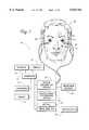
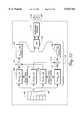
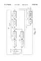
- FIG. 1is a block level schematic diagram showing the major components of the VEA system, including dual ICP prostheses inserted in the ear canal of an individual; a probe microphone system; and a computer system including a digital audio synthesizer module, a digital audiometer module, and a virtual acoustic space measurement module according to the invention;
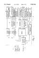
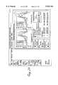
- FIG. 2is a block level schematic diagram of a digital audio synthesizer module according to the invention.
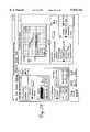
- FIG. 3is a block level schematic diagram of a digital audiometer module according to the invention.
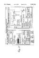
- FIG. 4is a block level schematic diagram of a virtual acoustic space measurement module according to the invention.
- FIG. 5is a block level schematic diagram of a virtual acoustic space measurement system according to the invention.
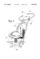
- FIG. 6is a perspective view of an adjustable chair used for positioning a patient's head during virtual acoustic space testing
- FIG. 7is a schematic diagram showing speaker arrangement in a virtual acoustic space measurement system, including transverse plane speakers, and sagittal plane speakers according to the invention
- FIG. 8is a schematic diagram showing an example of transfer function interpolation at a point i 3 from transfer functions, measured at points m 1 and m 2 in a two-dimensional transverse plane according to the invention
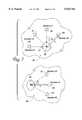
- FIG. 9is a schematic diagram showing an example of realization of a realistic listening scenario for unaided hearing evaluation conditions, and in particular showing a teacher-talker/child-listener scenario including direct acoustic paths P R1 and P L1 and early reflection paths P R2 and P L2 to the right and left ears of the child-listener according to the invention;
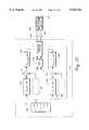
- FIG. 10is a block level schematic diagram showing an example of realization of a realistic listening scenario for unaided hearing evaluation conditions, and in particular showing a process representation of a teacher-talker/child-listener scenario during unaided evaluation according to the invention
- FIG. 11is a partially sectioned, perspective view showing an intra-canal prosthesis (ICP) for an ICP-ITE representing hearing aids for shallow ear canal placement according to the invention
- FIG. 12is a partially sectioned, perspective view showing an intra-canal prosthesis (ICP) for an ICP-ITC representing hearing aids for deep ear canal placement according to the invention
- FIG. 13is a perspective view showing an intra-canal prosthesis (ICP) face-plate end, including face-plate probe tube holders and probe tube placement according to the invention;
- ICPintra-canal prosthesis
- FIG. 14is a partially sectioned, side view showing an ICP core module for a two-part ICP configuration according to the invention.
- FIG. 15is a partially sectioned, side view showing adjustable vent inserts and an ICP-ITE sleeve for an ICP-ITE configuration according to the invention
- FIG. 16is a partially sectioned, side view showing an ICP-ITC sleeve for a two-part ICP configuration according to the invention.
- FIG. 17is a partially sectioned, side view showing a complete two-part ICP-ITC assembly according to the invention.
- FIG. 18is a partially sectioned, side view showing an ICP having a programmable vent according to the invention.
- FIG. 19is a partially sectioned, side view showing a hearing aid and direct acoustic coupling method to an ICP, including direct acoustic coupling via a magnetic attraction method according to the invention
- FIG. 20is a partially sectioned, side view showing a hearing aid and direct acoustic coupling method to an ICP, including direct acoustic coupling via an acoustic coupler method according to the invention
- FIG. 21is a partially sectioned, side view showing a hearing aid and direct acoustic coupling method to an ICP, including a programming and acoustic coupling interface according to the invention
- FIG. 22is a partially sectioned, side view showing a hearing aid and acoustic coupling to an ICP via an acoustic coupler tip according to the invention
- FIG. 23is a block level schematic diagram showing an example of a fitting process provided by the virtual electroacoustic audiometer system according to the invention.
- FIG. 24is a graphic computer generated display showing a reference measurements module according to the invention.
- FIG. 25is a graphic computer generated display showing an unaided evaluation module according to the invention.
- FIG. 26is a graphic computer generated display showing a predicted aided module according to the invention.
- FIG. 27is a graphic computer generated display showing a simulated aided evaluation module according to the invention.
- FIG. 28is a graphic computer generated display showing an aided evaluation module according to the invention.
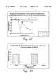
- FIG. 29is a line graph plotting the variability of measured SPL versus distance of probe tip from tympanic membrane for 5 kHz and 15 kHz tones for an individual according to the invention.
- FIG. 30is a bar graph plotting the measured SPL for 5 kHz and 15 kHz during probe advancing at 6 mm from tympanic membrane according to the invention.
- FIG. 31is a bar graph plotting the measured SPL for 5 kHz and 15 kHz during probe advancing at 5 mm from tympanic membrane according to the invention.
- FIG. 32is a bar graph plotting the measured SPL for 5 kHz and 15 kHz during probe advancing at 4 mm from tympanic membrane according to the invention.
- FIG. 33is a block level schematic diagram showing an example of a teacher-talker/child-listener scenario using predicted aided evaluation for the right ear according to the invention.
- FIG. 34is a block level schematic diagram showing an example of a teacher-talker/child-listener scenario using simulated aided evaluation for the right ear according to the invention.
- FIG. 35is a block level schematic diagram showing a simulated hearing aid with directional microphone according to the invention.
- FIG. 36is a block level schematic diagram showing an example of the realization of realistic listening scenarios for aided hearing evaluation conditions according to the invention.
- FIG. 37is a block level schematic diagram showing an example if the prediction and simulation of oscillatory feedback of a simulated hearing aid.
- Windowrefers to a graphical area displayed on a computer screen, that represents a collection of controls, objects, entry fields, and plots, that are grouped together according to a logical functional manner.
- Iconizedrefers to an active window that is shown as an icon. Its display is disabled but may be enabled by clicking on the icon on the computer screen.
- the virtual electroacoustic audiometer (VEA) described hereinis a unitary instrument that is used in the hearing assessment in the unaided, simulated aided, and aided conditions.
- the VEAalso offers new methods for hearing aid fitting and analysis using a combination of digital synthesis of realistic acoustic stimuli and in-the-ear-canal response measurements throughout the assessment and fitting processes.
- FIG. 1shows the main components of the preferred embodiment of the VEA system 15.
- a pair of intra-canal prostheses (ICP) 22is inserted in the ear canal 21 of an individual for delivering acoustic stimuli 25 in a manner similar to that of a hearing aid.
- Each ICPcontains a receiver, i.e. a speaker, for transmitting acoustic signals to the tympanic membrane 26.
- the ICPalso contains a probe tube 24 for measuring the acoustic response that results from the unique interaction of the receiver-produced acoustic stimuli and the ear-canal characteristics of the individual.
- a probe microphone systemconsisting of a probe tube 24 and probe microphone 23 measures acoustic signals from the ear canal 21 and provides electrical signals representative of the acoustic signals.
- a response keyboard 27is provided to register a response from the test subject 20 during various hearing evaluation tests.
- Each ICP receiver 22is electrically connected to a digital audiometer module 19 that provides an interface to various audiometric transducers including the ICP receiver 22 and probe measurement system 23.
- the digital audiometer moduleis connected to a digital audio synthesizer module 18 and a virtual acoustic space measurement module 14 via various inter-module cables.
- the virtual acoustic space measurement moduleincludes an output terminal 16 for connection to a plurality of test speakers.
- These modulesmay be contained at or within a standard personal computer (PC) 11 that also contains standard computer accessories such as memory storage devices 17, a display monitor 10, a keyboard 12, and a mouse 13. Memory storage devices are collectively referred to as system memory 17.
- the digital audio synthesizer, digital audiometer, and virtual acoustic space measurement modulesare connected to the personal computer system via the Industry Standard Architecture (ISA)-bus interface 34 and ISA-bus 39 of the personal computer (see, for example FIG. 2).
- Digital data representing audio sourcesare retrieved from the system memory via the bus interface 34, and are digitally processed by a digital signal processor 33 within the digital audio synthesizer module 18.
- the digitally processed dataare then converted to analog form using an digital-to-analog converter 35 that typically operates at conversion rate of 44.1 kHz, or at another rate depending on the desired signal bandwidth required.
- the digital audio synthesizer modulealso receives analog signals representing audio signals via its input connector 31 from external audio sources such as tape or CD players (not shown). Received analog signals are converted to digital signals by the analog-to-digital converter 32 for signal processing via digital signal processor 33.
- Multiple digital audio synthesizer modulesmay be used to enhance the system's digital signal processing capability. This is particularly useful for parallel real-time binaural signal synthesis. Multiple digital audio synthesizer modules are cascaded by connecting the output 38 of one digital audio synthesizer module to the auxiliary input 30, or input 31 of another digital audio synthesizer module. The internal and auxiliary signals are combined within the module at a summing node 36 prior to output. In the preferred embodiment of the invention, two digital audio synthesizer modules are used. Each module employs a Motorola DSP56001 digital signal processor clocked at 40 MHz.
- the analog output 38 from the digital audio synthesizer module 18is routed to the mixer 45 of the digital audiometer module 19 (FIG. 3) via a connector 42.
- Analog audio signals received at the digital audiometer moduleare mixed via mixer circuit 45, amplified via an audio amplifier circuit 46, and impedance matched and routed to various audiometric transducers via an audiometric transducer interface circuit 49.
- Outputs to audiometric transducersinclude ICPs 50 (discussed above, and in further detail below), bone vibrators 51, a headphone 52 (not shown), and other conventional methods of delivering sounds to the ear of an individual.
- Amplified signals from the audio amplifier 46are also sent to the digital audio synthesizer module input 31 from an audio buffer circuit 47 output connection 48.
- the mixer circuit 45also includes connections for receiving audio signals from ICP microphones 55, an operating clinician microphone 56, and a patient microphone 57, via a microphone amplifier 58.
- External line-level signals received at input connectors 53are also amplified via an amplifier 54 and sent to mixer circuit 45.
- a response keypad interface circuit 60is employed to interface the system to the response keypad via a connector 59 to register an individual's response to acoustic stimuli during various audiometric evaluation processes.
- the operating clinician microphoneconnected to the digital audiometer module, allows the operating clinician to communicate with the patient via the ICP pair.
- the patient microphoneallows the patient to communicate back to the operating clinician during certain audiometric tests that require verbal responses from the patient.
- the patient microphoneis also used in occlusion effect measurements, as are described in more detail below.
- the digital audiometer modulealso includes a PC-BUS connection 43 and PC-BUS interface circuit 44 that link the digital audiometer module to the VEA to coordinate module operation at the system level.
- the VEAalso includes a virtual acoustic space measurement system (FIG. 5) that is used to evaluate the individual's acoustic transfer function set.
- a block diagram of the virtual acoustic space measurement module 14is shown in FIG. 4.
- the virtual acoustic space measurement modulereceives electrical signals, representing various acoustic signals, from the digital audio synthesizer module output connectors 38 via a set of input connectors 64. Input signal level adjustment and routing is accomplished via a mixer circuit 65, an audio amplifier circuit 66, and a speaker routing and interface circuit 71.
- the output of the virtual acoustic space measurement moduleis thence coupled to various test speakers in a speaker array 16.
- the virtual acoustic space measurement modulealso includes a PC-BUS connection 68 and PC-BUS interface circuit 67 that link the virtual acoustic space measurement module to the VEA to coordinate module operation at the system level.
- Such coordinationincludes processing information indicative of patient head position connected to the module from a patient head positioning sensor via a connector 70 and a positioning sensor interface circuit 69.
- An adjustable chair 78is preferably used to ensure proper ear positioning within the measurement space, as shown in FIG. 6.
- a vertical adjustment lever 79adjusts the vertical position of the individual on the chair.
- a back adjustment knob 81adjusts a chair back support 80.
- the head support 82is adjustable to support the head of the individual seated on the chair.
- An ear position reference arm 84provides a target reference by pointing a set of ear canal opening pointers 83 to the individual's ear canal openings.
- the ear position reference arm 84is preferably removable from the ear area via a reference arm vertical adjustment knob 85 to minimize acoustic reflections into the ear area during transfer function measurements.
- An infrared tracking methodmay also be used to position and maintain the head in the proper position with respect to the speaker array 16, FIG. 5; 89-94, FIG. 7).
- a light-reflective target object(not shown) placed just below the ear lobe of the individual, may be used to reflect the infrared light from the incident infrared light emitter. Proper ear placement is indicated by reflected light which is detected by the positioning sensor interface 69 (FIG. 4).
- the virtual acoustic space measurement systemgenerates various sets of transfer functions that are used during the hearing evaluation process.
- a transfer function of a linear systemdefines a complex function H(jw) having magnitude and phase characteristics that are dependent on frequency (w).
- the transfer function set in the virtual acoustic space measurement systemis obtained from a set of acoustic sources, such as speakers, positioned in a three-dimensional space.
- the preferred speaker setupis an array of six speakers 89-94 positioned at an equal distance (d) from a patient head reference point 88, as shown in FIGS. 5 and 7.
- the head reference point 88is defined as the point bisecting the line joining the centers of the openings of the ear canal 21.
- Speakers 1 through 4are positioned at azimuth angles 0°, 45°, 315°, and 270°, respectively, as shown in FIG. 7 at (step).
- Three of the speakers, i.e. #1 (89), #5 (93), and #6 (94)are located in the sagittal plane 96 containing the head reference point 88.
- Speakers #1, #5, and #6are positioned at altitude angles of 0°, 45°, and -45°, respectively, as shown in FIG. 7 at B.
- a set of transfer functions for the six-speaker configuration shown in FIG. 7allows six pairs, i.e. right and left ear measurements, of frontal measurements where the head is facing speaker #1. An additional six pairs of back measurements are preferably taken where the head is facing opposite (not shown) to speaker #1. Accordingly, a complete transfer function set consists of 12 pairs of measurements that represent finite points in a sphere of a radius (d). Of the twelve paired measurements, eight paired measurements are in the transverse plane and six paired measurements are in the sagittal plane. Two paired measurements are common to both planes. Paired measurements contain not only individual transfer functions for each ear, but also contain the interaural phase relationship with respect to each speaker.
- a transfer function measurement set with a pair of probes placed near the tympanic membrane in the unoccluded ear canalis referred to herein as the unaided transfer function H ua (p n ,jw), where p n is the location of speaker n defined by polar coordinates d, ⁇ , and ⁇ , where d is the distance between the speaker and the head reference point as shown in FIG. 7 at A.; ⁇ is the azimuth angle of sound incidence with the respect to transverse plane as shown in FIG. 7 at A.; and ⁇ is the altitude angle with respect to the sagittal plane as shown in FIG. 7 at B.
- H ua (p n ,jw)represents the acoustic transfer function that results from sound propagation from a speaker #n to the tympanic membrane when various acoustic factors are considered, including atmospheric propagation losses, effects of head, torso, neck, pinna, concha, ear canal, tympanic membrane, and middle ear impedance.
- Transfer function measurements with a probe tube placed on the face-plate of the ICPmay also be made. These measurements are referred to herein as H fp (p n ,jw), which represent the transfer function from a speaker #n to a face-plate (fp) of the ICP (discussed in more detail below), at a location representative of the microphone position on a face-plate of a simulated hearing aid.
- a transfer function H(p.sub.(d, ⁇ , ⁇ ), jw) at an arbitrary point p d , ⁇ , ⁇ in space at coordinates d, ⁇ , and, ⁇can be interpolated from the set of measured transfer functions as shown in FIG. 8.
- the sound pressure from an audio sourceis inversely proportional to distance in normal atmospheric conditions.
- a transfer function of a point in spacecan be approximated by the weighted average of the two nearest measured transfer functions. FIG. 8.
- L at (jw)is the atmospheric loss transfer function due to atmospheric absorption and spreading roll-off of sound.
- interpolationcan be used to approximate any transfer function at an arbitrary point in a three-dimensional space from the weighted average of the nearest set of measured transfer functions.
- the accuracy of interpolated functionscan be improved if additional measurements are made with additional speakers and/or speaker-head orientations.
- the preferred embodiment of the inventionemploys a practical compromise between the number of speakers, e.g. six in the embodiment of the invention described herein, and individual orientations, e.g. two: a front and a back orientation.
- non-linear weighting for transfer function interpolationmay be more appropriate if determined from statistical data obtained from transfer function measurements of large number of individuals.
- VEA systemOther transfer functions measured by the VEA system include:
- H icp-rec (jw) transfer functionwhich represents the ICP receiver to in-the-ear-canal electroacoustic transfer function, as measured by a probe when the ICP is positioned in the ear canal of the individual;
- H icp-mic (jw) transfer functionrepresenting the electroacoustic transfer function from an ICP speaker to the microphone of the hearing aid used during the hearing aid evaluation
- H icp-fb (jw) transfer functionrepresenting the acoustic leakage, i.e. acoustic feedback, from the receiver of the ICP measured at face-plate of the ICP.
- H ua (p n ,jw), H fp (p n ,jw), H icp-rec (jw), H icp-mic (jw), and H icp-fb (jw)are employed in various combinations to digitally synthesize acoustic signals, representing unaided, simulated aided, or aided listening conditions, with realism that is not possible with conventional evaluation and fitting methods.
- a teacher-talker 101 and a child-listener 102 acoustic environment 100is created as follows: direct acoustic paths p R1 and p L1 , and reflection paths p R2 and p L2 , for right and left ears of the child-listener 102 are represented by transfer functions interpolated from previously measured transfer functions of the child.
- FIG. 10The acoustic realization of the environment of FIG. 9 is shown in FIG. 10, in which a digital audio file 107 that represents teacher-talker speech is retrieved from a system memory 106 and digitally processed by digital signal processor 114.
- the digital signal processorperforms signal processes H ua (p R1 ,jw) 108, H ua (p L1 ,jw) 110, H ua (p R2 ,jw) 109 and H ua (p L2 ,jw) 111, which represent the paths p R1 , p L1 , p R2 , and p L2 , respectively.
- Right and left ear path processesare summed at summing nodes 112 and 113 and are further processed with inverse transfer functions, 1/H icp-rec -Rt(jw) (116) and 1/H icp-rec -Lt(jw) (104), for right and left ICP receivers 119/120, respectively.
- the inverse transfer functionsare provided to cancel the acoustic transfer function that occurs between the ICP receiver and the residual volume of the ear canal as the sound is delivered.
- the processed right and left digital signalsare then converted to analog signals via a digital-to-analog converter 115 and routed to right and left ICPs via an audiometric interface circuit 117.
- the process of projecting a virtual audio image to a listener at a particular point in a three-dimensional space, such as teacher-talker speech to a child-listener,is referred to as spatialization.
- live-voice signals from the operating clinician via the operating clinician microphonecan be used, instead of digital audio data, for spatialization and delivery to the listener wearing the ICP pair.
- the virtual position and volume of the spatialized audio sourceare under the control of the virtual audiometer system of the present invention, as is explained in more detail below.
- Transfer function measurements of linear time-invariant systemstypically employs discrete or swept pure tone acoustic stimulus.
- Other stimuliinclude speech-noise, white-noise, and other speech-like noise signals.
- Pseudo-random noise sequences and other signalshave also been used to reduce the time required to compute the transfer function.
- Computational methodsinclude Fast Fourier Transform (FFT), Maximum-Length Sequence (MSL), and Time-Delay Spectrometry (TDS) (see Rife.
- FFTFast Fourier Transform
- MSLMaximum-Length Sequence
- TDSTime-Delay Spectrometry
- MSL and TDS measurementinclude reduction of room reflection effects on the transfer function.
- One important component of measured transfer functions used in the present inventionis the direct path transfer function.
- the VEA's probe microphonesare calibrated at the head reference point when the VEA is first installed in its clinical setup. These calibration data, stored in the system memory, are subsequently used during transfer function measurements to correct for the unique frequency response characteristics of each probe microphone used and the unique characteristics of room acoustics.
- FIG. 11is a partially sectioned, perspective view showing an intra-canal prosthesis (ICP) for an ICP-ITE representing hearing aids for shallow ear canal placement
- FIG. 12is a partially sectioned, perspective view showing an ICP for an ICP-ITC representing hearing aids for deep ear canal placement
- FIG. 13is a perspective view showing an ICP face-plate end, including face-plate probe tube holders and probe tube placement
- FIG. 14is a partially sectioned, side view showing an ICP core module for a two-part ICP configuration
- FIG. 15is a partially sectioned, side view showing adjustable vent inserts for an ICP-ITE;
- FIG. 16is a partially sectioned, side view showing an ICP-ITC sleeve for a two-part ICP configuration
- FIG. 17is a partially sectioned, side view showing a complete two-part ICP-ITC assembly
- FIG. 18is a partially sectioned, side view showing an ICP having a programmable vent
- FIG. 19is a partially sectioned, side view showing a hearing aid and direct acoustic coupling method to an ICP, including direct acoustic coupling via a magnetic attraction method
- FIG. 20is a partially sectioned, side view showing a hearing aid and direct acoustic coupling method to an ICP, including direct acoustic coupling via an acoustic coupler method
- FIG. 21is a partially sectioned, side view showing a hearing aid and direct acoustic coupling method to an ICP, including a programming and acoustic coupling interface; and FIG. 22 is a partially sectioned, side view showing a hearing aid and acoustic coupling to an ICP via an acoustic coupler tip, all according to the invention.
- the ICP of FIGS. 11 and 12each have a receiver 136, while the housing 129 in the embodiment of FIG. 11 is different from the housing 152 of the embodiment of FIG. 12.
- the intra-canal-prosthesisshown in FIGS. 11-22, consists mainly of a receiver 136, a receiver port 199, a probe tube 133 inserted in probe tube canal 134, vent inserts 128 inserted in vent canal 130, a probe microphone 131, a face plate 122, and a housing made of a flexible material, such as an acrylic.
- the ICPis generally designed to represent physical and electroacoustic characteristics of a desired type of hearing aid with the exception of the signal processing and generation, which is performed by the audio synthesizer board of the computerized virtual electroacoustic audiometer system.
- FIGS. 11 and 12show ITE and ITC ICPs that represent hearing aids having shallow and deep canal placement, respectively.
- the receiver 136 used in the preferred embodiment of the present inventionwas chosen for its acoustic characteristics, which are similar to receivers used in commercially available hearing aids, as well as its very low noise output characteristics. ICP receiver variations from simulated hearing aid receivers are stored in the VEA system memory as a correction transfer function used during various simulation processes.
- the probe tube 133preferably made of a silicone rubber material and having a diameter of approximately 1 mm, is inserted in the probe tube canal 134 of the ICP as shown in FIGS. 11-22.
- a vent canal 130is preferably provided for pressure equalization in the ICP-ITC versions that have deep canal insertion depths (FIGS. 12 and 17), and to accommodate vent inserts for the ICP-ITE version having shallow canal insertion depths (FIGS. 11 and 15).
- a vent canalallows the insertion of various vent inserts into the vent canal to achieve desired in situ acoustic characteristics.
- a vent insert of relatively large diametermay be used to reduce the occlusion effect that results from increased perceived volume of the individual's own voice.
- a smaller vent insertmay be used to eliminate acoustic leakage from the receiver via the vent insert.
- a miniature connector socket 138 and connector plug 123electrically connects the ICP to the VEA system via attached connector cable 125.
- the VEA systemin conjunction with the probe microphone system, permits measurements of the occlusion effects versus ICPs and vent types, as is explained later.
- the ICPalso contains two probe tube holders 124 and a placement handle 126 for placement of the probe tube, as shown in FIGS. 11, 12, and 17.
- FIG. 13shows a more detailed illustration of a face plate 122, including the face plate tube holders 124.
- a ICP/ITC sleeve 156, and a hearing aid microphone position 132are also shown. This configuration is used when measuring acoustic leakage feedback and face-plate transfer functions.
- the ICP housing(129, FIG. 11; 152, FIG. 12) is preferably made of a soft flexible material with acoustic baffling effects to provide comfort and acoustic sealing.
- Several versions of the ICPcan accommodate a variety of ear canal sizes. For example, a small housing version is more suitable for pediatric populations, while a larger version is suitable for adults who have large ear canals.
- the ICP, shown in FIGS. 11 and 12is preferably disposable to avoid contamination from individuals who have infected ear canals.
- FIGS. 14-17An alternate embodiment of the invention provides a two-part ICP configuration, as shown in FIGS. 14-17.
- a core part 169(FIG. 14) is inserted in a variety of disposable sleeves 177, as shown in FIGS. 15 and 16. This option provides an economical alternative to the configuration shown in FIGS. 11-13 because only the sleeve component is disposable.
- the core part 169is encapsulated in a protective material 166, preferably having semi-flexible properties.
- a decoupling capacitor 167may be used to filter extraneous electromagnetic signals that cause audible noise.
- the sleeve part shown in FIGS. 15 and 16is typically made of flexible material, such as a soft acrylic, such that the ICP fits comfortably into a variety of ear shapes and sizes.
- FIG. 16shows a sleeve suitable for deep canal insertions, representing ITC and CIC hearing aid types. Also shown in FIG. 16 is an acoustic baffle system 186 that provides an acoustic seal while the ICP is inserted in the ear canal.
- FIG. 15shows an ICP sleeve for shallow canal insertions representing ITE hearing aid types.
- the ICP coreis inserted in the sleeve cavity 179 of any ICP, including those shown in FIGS. 15 and 16.
- the specific size of the ICP sleeve selected by the operating cliniciandepends upon the test performed, individual canal size, and hearing aid simulation requirements.
- FIG. 17,represents an ICP-ITC assembly.
- FIG. 18shows a variation of the vent mechanism where the size of the vent is electronically controlled and adjusted (see Zdeblick, K., A Revolutionary Actuator For Microstructures, Sensors Magazine, eb. 1993).
- Thisis accomplished by employing programmable micro-valve 193 (such as the NO-300 manufactured by Redwood Microsystems of Redwood City, Calif.) which contains a silicon diaphragm 194 which is to regulate the size of the vent attached to the vent canal 197 via the micro-valve port 195.
- Typical vent size rangeis between 0.032 and 1.5 mm, according to the voltage level supplied from the virtual electroacoustic audiometer module in response to operating clinician test selections.
- the ICPis also used in a novel way to test a new type of hearing aids adapted to interface to the ICP, as shown in FIGS. 19-22.
- the ICP of the present inventionpresents acoustic signals directly to the microphone 211 of the hearing aid 214.
- the acoustic coupling of the present inventionspans a minimal distance typically less than 15 mm.
- FIGS. 19 and 21show an embodiment of the invention in which acoustic coupling is accomplished via a magnetic attraction method.
- the ICP receiver 136is coupled to the hearing aid microphone 211 via magnetic attraction between a magnet disk 206 on the receiver end of the ICP and another magnet disk 209 near the hearing aid microphone port 210, and which is part of the face-plate 218 of a hearing aid 214, as shown in FIG. 19.
- a sealing ring 205provides acoustic sealing to minimize leakage in the coupling.
- FIG. 21provides a programmable hearing aid circuit 253 that allows dynamic ITE testing via control signals routed from the VEA over a programming cable 257.
- FIG. 21shows an electrically programmable hearing aid with a programming cable 257 connecting the hearing aid circuit to the VEA of the present invention.
- These hearing aidscontain circuits that are programmable or adjustable, typically via electrical signals.
- the shown programming interface at the face-plateis via the battery holder which is adapted to route programming electrical signals to the hearing aid circuit.
- the programming signals and interface methodsare typically unique to the hearing aid model as provided by the specification of the hearing aid circuit used. These programming signals and interface methods are known to persons skilled in the art of hearing aid design.
- Other programmable hearing aids currently commercially availableemploy ultrasonic or infra-red signals with the appropriate signal interface circuits within the hearing aid.
- An alternative acoustic coupling methodcouples the ICP receiver 136 to the hearing aid microphone 211 via a acoustic coupler 243, as shown in FIG. 20.
- the extended microphone port 242unique to the present invention, also acts as a handle to facilitate insertion and removal of hearing aid 214 during its normal use.
- FIG. 22Another embodiment of the invention, shown in FIG. 22, employs an acoustic coupler 290 adapted for insertion into a microphone port 299 of the hearing aid 214.
- the microphone port 299is recessed to accommodate an acoustic coupler tip 291.
- Another acoustic coupling methodemployees a suction-cup ring to couple the ICP receiver to existing conventional hearing aids that are not equipped with special interface parts.
- One major advantage of the direct acoustic coupling of the present inventionis to improve the signal-to-noise ratio at the microphone of the hearing aid while the aid is being adjusted or evaluated. This is primarily accomplished by acoustically isolating the microphone of the hearing aid from ambient room noise via its coupling to the ICP.
- Hearing aids of the present inventionalso employ a probe tube canal to allow for probe tube insertion and subsequent in-the-ear-canal acoustic measurements via the probe measurement system as shown in FIGS. 19-22.
- the conventional method of in-the-ear-canal measurements with hearing aidsinvolve probe placements beneath the hearing aid which subjects the probe to pinching effects, thus affecting the accuracy of the measurement.
- placing the probe tube beneath the hearing aidcreates an acoustic leakage path which causes oscillatory feedback.
- the probe tube canal of the present inventionalso provides an improved method of advancing the probe while the hearing aid is placed in the ear canal.
- the sequence of these phases as outlined in FIG. 23represents a typical fitting process unique to the system of the present invention.
- the fitting process offered by the virtual electroacoustic audiometer system in the preferred embodiment of the present inventionis implemented in five phases: (1) reference measurements 264, (2) unaided hearing evaluation 265, (3) predicted aided evaluation 266, (4) simulated aided evaluation 267, and (5) aided evaluation 268.
- individual phases or a components of each phasecan be administered individually, or in other sequence as suitable for the individual under hearing evaluation.
- Each process phaseis implemented in a graphical module, as shown in FIGS. 24-28.
- the first phasei.e. reference measurements
- a reference measurements module(FIG. 24) that contains a reference measurement window (shown open in FIG. 24) and a signal model window (shown iconized in FIG. 24).
- the reference measurement windowallows for measurements of various transfer functions that are used later throughout the fitting process.
- the unaided transfer function H ua (p n ,jw) described aboveis measured when the 3D-REUR (3 Dimensional Real-Ear Unaided Response) option is selected. Measurements are obtained from the frontal (facing speaker #1) or back (facing opposite speaker #1) orientations, depending on the Front/Back option selected. Plots of right and left ear transfer functions can be displayed in either transverse or sagittal plane depending on the Transverse/Sagittal option selection.
- FIG. 24shows a set of 8-paired H ua (p n ,jw) transfer functions in the transverse plane. The measurement is performed by positioning the individual centrally to the speaker array (discussed above) and placing right and left probe tubes in their respective unoccluded ear canal.
- Another novel feature of the inventionis the ability to measure and quantify the occlusion effect of the simulated hearing aid, as well as the fitted hearing aid.
- a reference measurement with the ear canal unoccludedmust be taken. The procedure, briefly described here, is to request the individual to utter a vowel, preferably a vowel with high energy contents in its low frequency spectrum, such as "ee.”
- a measurementis taken with the probe positioned near the tympanic membrane.
- the occlusion effect reference measurementi.e. unoccluded, is saved for occlusion effect measurement with the ear canal occluded using either the ICP or the hearing aid, as is explained below.
- the occlusion effect reference measurementis performed when the occlusion reference option is selected.
- the face-plate transfer function H fp(p n ,jw) (plots not shown) is measured when the Face-Plate Response option is selected.
- the ICPis placed in the ear and the probe tube tip is placed in the microphone position 132 of the face-plate as shown in FIG. 13.
- H icp-recThe ICP-receiver to real ear transfer function, H icp-rec (jw) is measured when ICP Calibrate option is selected. This requires the probe tube to be inserted in the probe tube canal of the ICP, and the tip of the tube near the tympanic membrane.
- the frequency dependent standing wave patternsare well characterized and known to persons skilled in the art of acoustics and particularly real ear acoustic measurements.
- the new method of the inventioninvolves acoustic presentation of a dual tone, one at a low frequency in the range of 1 kHz to 5 kHz, and a second at a range of 15 kHz to 20 kHz.
- the acoustic response to tone signals delivered either via a speaker or the ICP receiver, depending on measurement,is continuously measured by microphone probe system and displayed on the monitor, as shown in FIGS. 30-32.
- a plot of the acoustic response in an ear of an individual for each tone, shown in FIG. 29,indicates a characteristic rise in the low frequency response and a notch in the high frequency response as the probe is advanced closer to the tympanic membrane. This notch occurs at approximately 5 mm from the tympanic membrane for the 15 kHz tone.
- Monitoring of the relative response characteristics during probe insertionprovides a visual and computer-assisted method to indicate proper probe positioning as shown in the spectrum plots of FIGS. 30-32. The end of this procedure is generally indicated when a significant notch, typically exceeding 15 dB as shown in FIG. 31, followed by a significant rise in the high frequency, i.e. second tone, response.
- the low frequency, i.e. second tone, responseshows only a small increase, within 3 dB, as the probe is inserted closer to the tympanic membrane.
- the object of this procedureis to position the probe such that minimal standing waves are present at frequencies of interest during transfer function measurements. For example, if unaided response measurements up to 6 kHz are desired, advancing the probe until detecting a notch in 15 kHz response ensures measurement errors not to exceed 2.5 dB at 6 kHz. Improved accuracy can be achieved by selecting a higher frequency for the second tone, although this increases the chance of advancing the probe too far, resulting in touching the surface of the tympanic membrane, an occurrence that is generally safe but that may cause discomfort.
- tonesincluding a single, triple, composite, and other signals can also be used to implement the above procedure of continuously measuring the response to various acoustic stimuli and detecting an appropriate stopping point during probe advancement, with little regard to probe distance to the tympanic membrane.
- the appropriate probe positionis referred to hereafter as the probe reference point.
- the second phase, unaided evaluationis implemented by an unaided evaluation module, shown in FIG. 25, which consists of an unaided analysis window, shown open in the figure; a spatialization window, also shown open; a signal model window, shown iconized; and an audiometric evaluation window, also shown iconized.
- an unaided evaluation moduleshown in FIG. 25, which consists of an unaided analysis window, shown open in the figure; a spatialization window, also shown open; a signal model window, shown iconized; and an audiometric evaluation window, also shown iconized.
- the unaided analysis windowallows for various in-the-ear-canal measurements and displays for hearing evaluation in the unaided condition while the ICP is inserted in the ear canal.
- Measurements and plotsinclude Audiogram spectrum, Distortion, Time Analysis, Spectrogram, and 2-CC curves. Acoustic stimuli, measurement methods, and associated plots for these tests are known to persons skilled in the arts of audiology and signal analysis.
- the Audibility Spectrogramis a new feature that is unique to the present invention as described below.
- the Audibility Spectrogramis a spectral plot showing the audibility of a signal with respect to the hearing profile of the individual and the critical audibility features of an acoustic signal.
- the audibility spectrogramis essentially a three-dimensional matrix represented in a two-dimensional plot that indicates signal dynamics (time) and Critical Audibility Regions (CAR) versus frequency, as shown in FIG. 25.
- CARsshown as the outer contours, are specific to each signal segment that is selected from the signal model window.
- CARs of a speech segmentare defined by the critical sound features, such as the energy of significant formats in vowels, the energy of fundamental frequency of voicing, the energy of aperiodic frequency sounds, and other criteria known to effect intelligibility, detection, or identification, depending on the signal model selected.
- the Audibility Spectrogram plotsare derived by combining spectrograms of analyzed signals and defined CARs, and probe measured spectrograms computed and compared with the measured hearing profile of the individual at the CARs.
- Measured spectrogram values that fall below the threshold of hearing for-the individualare assigned to Below Threshold (B-Thresh) values which define the outer contour region, within the CAR; while measured spectrogram values that exceed the threshold of hearing within CAR are assigned Above Threshold (A-Thresh) values which define a region within the Below Threshold region; and measured spectrograms values that exceed the uncomfortable loudness level (UCL) of the individual are assigned Above-UnComfortable Loudness level (A-UCL) values which define the inner-most contour regions.
- B-ThreshBelow Threshold
- A-ThreshAbove Threshold
- measured spectrograms values that exceed the uncomfortable loudness level (UCL) of the individualare
- the resulting color-coded plotis typically contour shaped for speech signals.
- any type of acoustic signalcan be assigned CARs and a corresponding audibility spectrogram based on the individual's measured hearing profile.
- the objective of the Audibility Spectrogram plotis to provide a quick graphical means of indicating the audibility of dynamically received acoustic signals by taking in consideration the individual's hearing profile and the critical audibility features of a signal model. This plot is particularly important in hearing aid fitting optimization processes during predicted aided, simulated aided, and aided evaluation.
- the spatialization windowpermits selection of signal presentation mode, either in Spatialized or Intracranial modes.
- Spatialized modepresents selected sources and background signals to be delivered to both ears via inserted ICPs according to the selected spatial relationship of head, sources, background, and boundaries, as shown in FIG. 25.
- Spatial relationshipsinclude the distance between the audio source and the head reference point (d), azimuth angle ( ⁇ ), and altitude angle ( ⁇ ).
- Intracranial modeoffers the conventional sound presentation method where selected signals and corresponding levels are delivered without spatialization to one or both ears.
- the Signal Model windowpermits the selection of source and background signals and corresponding level.
- Source selectionmay be of pure tone type, speech, music, or any signal of audiological significance.
- Background signalsare typically competing speech, environmental noise, and other signals of audiological significance.
- the level of signals selected in the spatialized modeis preferably in dB SPL calibrated to 1 meter from the source in free field.
- the measured in-the-ear-canal acoustic responseis preferably displayed in dB SPL as measured by the probe microphone system.
- source and background signalsare routed to right, left, or both ears as in conventional audiometry.
- the level of signals selected in the intracranial modeis preferably in dB SPL.
- the H icp-rec (jw) transfer function measurement via the ICP calibration procedure described abovepermits level selection in dB SPL.
- measurements via the probe microphone systemcan be made as needed to ensure that the probe and the ICP remain properly positioned in the ear canal.
- a specific selection of source and background signal type, levels, and spatialization modeis defined as a signal model.
- One or more signal modelscan be selected, saved, and retrieved by the system for presentation and analysis purposes.
- a signal modelcan represent any individual or a combination of acoustic signals/scenarios, including speech, background noise, music, pure tone, masking noise, composite signals, and other audiologically significant signals.
- the audiometric evaluation windowallows for various conventional audiometric measurements to be taken. This includes threshold audiogram, most comfortable level (MCL), uncomfortable loudness level (UCL), speech reception threshold (SRT), and various other audiometric measures known to persons skilled in the art of audiology.
- MCLmost comfortable level
- UDLuncomfortable loudness level
- SRTspeech reception threshold
- the preferred methodmeasures the in-the-ear-canal response in absolute sound pressure level (SPL) terms.
- Another feature of the inventionrelates to the modes of audiometric signal presentation.
- spatialized or intracranial listening modes selected from the Spatialization windownot only affect the presentation selected from the Signal Model window, but also the Audiometric Evaluation window as well.
- a standard audiological word listsuch as NU-6 or W-22, commonly used in conventional speech audiometry, can be presented in the conventional intracranial mode, or alternatively, in the spatialized mode unique to the invention.
- the signal process of a spatialized unaided evaluationinvolves the unaided transfer function H ua (p n ,jw), interpolated based on selections of the spatialization window, and the H icp-rec (jw) transfer function.
- H uap n ,jw
- H icp-recjw
- the third phase, the predicated aided evaluation,is implemented by the predicated aided evaluation module.
- This moduleshown in FIG. 26, allows the operating clinician to select a hearing aid and predict its performance without the involvement of the hearing-impaired individual.
- the moduleconsists of a Hearing Aid Select/Adjust window, shown open; a Predicated Analysis window, shown open); a Signal Model window, shown iconized; a Spatialization window, shown iconized;and the Audiometric Evaluation module.
- the Signal Model, Spatialization, and Audiometric Evaluation windowsare essentially identical to those described in the Unaided Evaluation phase.
- the Hearing Aid Select/Adjust windowpermits hearing aid selection and subsequent adjustment.
- the predicated results of the selection/adjustmentare shown on the selected plots of the adjacent Predicted Analysis window.
- Hearing aid selectioncan be automatic or manual, depending on the hearing aid selection Automatic/Manual option selected.
- Automatic selectioninvolves selecting one or more hearing aids based on the fitting algorithm selected, and various other criteria selected by the hearing-impaired and the operating clinician.
- Conventional fitting formulae and methodssuch as POGO, Berger, and NAL-R, are provided.
- the preferred fitting methodis the dynamic audibility method which employs a rational such that Audibility Spectrogram is optimized. This corresponds to plots that maximize the Above-Threshold (A-Thresh) contour areas while minimizing Below-Threshold (B-Thresh) and Above-UnComfortable loudness Level (A-UCL) contour areas. Hearing aid models that best match the selected criteria are automatically retrieved from the system memory.
- a hearing aid modelcontains all of the necessary electroacoustic parameters that are used for signal processing of a signal model. The results of the signal process are used in the Predicted Analysis window for analysis and plotting purposes. Hearing aid parameters of a selected hearing aid model are adjusted automatically or manually depending on the hearing aid adjustment Automatic/Manual option and the fitting method selected.
- a hearing aid control parameter setis typically unique to the hearing aid model selected.
- the control parametersare: volume control (VC), Low Frequency Cut (LFC), compression Threshold Knee (TK), Microphone type (MIC), Receiver type (REC), and Vent Size selection which reflects vent size of the ICP inserted. If a different vent size is selected, either manually via the vent insert selection, or electronically via the programmable micro-valve vent selection, a new H icp-spkr (jw) transfer function is preferably measured to improve the accuracy of the analysis.
- the predicted analysis windowis essentially identical to the unaided analysis window, described above, with the exception of the signal processing model that includes the measured face-plate transfer function H fp (p n ,jw) (292, 293; FIG. 33), hearing aid transfer function H ha (jw) (294; FIG. 33), and the measured ICP receiver to real-ear H icp-rec (jw) transfer function for the aided ear (295; FIG. 33).
- the hearing aid H ha (jw) transfer functionis typically non-linear and varies depending on the hearing aid selected.
- the total hearing aid transfer function H ha-t (jw)typically includes transfer functions of the microphone H mic (jw), hearing aid circuit H ha-rec (jw), and the receiver H ha-rec (jw).
- the transfer function H ha (jw)differs from H ha-t (jw) by excluding the hearing aid receiver and, instead, including a receiver correction transfer function H Rec-corr (jw), that defines the difference between the predicted hearing aid receiver and the ICP receiver employed.
- This correction transfer function H Rec-corr (jw)is typically a linear transfer function and is supplied by the VEA system.
- the predicted aided analysis process for an aided right ear and unaided left ear for a child-listener/teacher-talker scenariois shown in FIG. 33.
- the results of the digital signal processare stored in the system memory 106 for analysis and display.
- the analysis of the predicted data in the system memoryincludes audibility analysis as described above.
- the plottingincludes an Audibility Spectrogram that indicates audibility contours of Below-Threshold, Above-Threshold and Above-UCL with respect to critical audibility regions (CRAs).
- FIG. 26shows improved audibility in the predicted aided condition versus unaided condition shown in FIG. 25, i.e. increased Above-threshold contour areas.
- Another prediction measurement unique to the present inventionis the measurement of occlusion effect caused by the insertion of the ICP into the ear canal that is characterized by the perceived amplification of the person's own voice.
- the present inventionprovides a method of measuring, subjectively and objectively, the magnitude of the occlusion effect.
- the subjective methodis performed by asking the individual wearing the ICP to evaluate his own voice when speaking. If the response is objectionable to the hearing-impaired candidate then an alternative ICP, representing a different hearing aid, may be considered.
- the objective methodinvolves the measured response via the probe system in the occluded ear canal and subtracting the occlusion effect reference measurement, i.e. unoccluded ear-canal measurement, as described above.
- the patient microphone 57external to the ear canal, is typically employed to record the individual's own voice during occlusion effect measurements to ensure constant intensity level during both unoccluded and occluded ear canal measurements (see Mueller, H. G., Hawkins, D. B., Northern, J. L., Probe Microphone Measurements: Hearing Aid Selection and Assessment, 1992, pp. 221-224).
- a unique feature of the present inventionis to eliminate not the only requirement of constant voice intensity, but also constant voice spectral characteristics. This is accomplished by adjusting the calculated occlusion effect measurement by the difference in the spectral characteristics of the individual's own voice.
- ICP-ITCThe occlusion effect created by two types of ICP, i.e. ICP-ITC and ICP-ITE, is shown in the plot of FIG. 27. This plot indicates a significant occlusion effect due to the ICP-ITE versus the ICP-ICP for an individual. This is expected since the ICP-ITE creates a greater residual volume, to which the occlusion effect is known to be directly proportional.
- ICP measurement at the probe reference pointis that all measurements taken are independent of the ICP selected or its placement in the ear canal.
- the H icp-rec (jw) transfer measurementis required whenever a new ICP is selected and inserted into the ear canal of the individual.
- Another measurement unique to the inventionis that of acoustic feedback caused by acoustic leakage from the ICP receiver, when simulating a hearing aid receiver, to the face-plate of the ICP, which simulates the face-plate of the hearing aid.
- the transfer function H icp-fb (jw) (337; FIG. 37), e.g. amplitude and phase response,is measured at the face-plate as described above.
- the opening created by the removal of the probe tube from the ICP probe tube canalis preferably plugged during the feedback measurement to exclude acoustic leakage due to the probe canal.
- a significant application of the feedback transfer functionis in the simulation, and thus prediction, of oscillatory feedback of the simulated hearing aid.
- This undesirable oscillatory feedbackmanifests itself in the form of whistling, which interferes with the normal operation of the hearing aid.
- the prediction and simulation of the oscillatory feedback of a simulated hearing aid having a selected settingis accomplished by incorporating the ICP feedback transfer function H icp-fb (jw) 337, as shown in FIG. 37.
- Oscillatory feedbackcan be audible to the individual wearing the ICP via the ICP receiver.
- the oscillatory feedbackcan also be measured via the ICP microphone system in conjunction with the VEA system. This feature allows the operating clinician to adjust the settings of the simulated hearing aid, particularly the gain, frequency response, and vent size, such that oscillatory feedback is minimized or eliminated.
- the VEA systemcan be employed to select automatically an alternate hearing aid or alternate hearing aid parameter set, such that oscillatory feedback is minimized or eliminated.
- the predicted aided analysis windowalso includes other analysis and corresponding plots of Audiogram, Distortion, Time Analysis, Spectrogram, 2-cc Curve. These are standardized measurements and plots that are known to persons skilled in the art of hearing sciences and technology.
- the 2-cc coupler curvesinvolve conversion of measured in-the-ear-canal response to standard 2-cc coupler curves using real-ear-to-2-cc coupler conversion formulas.
- Standard signal models, such as pure tones,are typically involved in the 2-cc coupler measurements (see Specification of Hearing Aid Characteristics, ANSI-S3.22-1987, American Standards National Institute).
- Other evaluation methods conceived and well within the means of the inventioninclude the Articulation Index (AI) measures for unaided, predicted aided, simulated aided, and aided conditions.
- AIArticulation Index
- An objective of the predicted aided moduleis to predict objectively the performance of a selected hearing aid according to the selected signal model, selected hearing aid parameter set, and the individual's hearing profile, without the involvement of the hearing-impaired individual.
- the fourth phase, simulated aided evaluation,is implemented by the simulated aided evaluation module, as shown in FIG. 27.
- This moduleallows the operator to select and optimize one or more hearing aids and simulate their audible characteristics.
- the moduleconsists of a Hearing Aid Simulation window, shown open; a Simulated Aided Analysis window, shown open; a Signal Model window, shown iconized; a Spatialization window, shown iconized; and the Audiometric Evaluation module, shown iconized.
- the Signal Model, Spatialization, and Audiometric Evaluation windowsare essentially identical to those described above.
- the Simulation Aided windowis essentially identical to the Hearing Aid Select/Adjust window of the Predicted Aided Evaluation module.
- the Simulated Aided analysis windowis essentially identical to the Predicted Analysis window.
- a major difference in the simulated aided evaluation moduleis the module's ability to synthesize simulated aided conditions and to present the audible results to the hearing-impaired individual. Another significant difference is that analysis is performed by the module based on measured, rather than predicted, data. The measured response is obtained via the microphone probe measurement system with the probe tip placed at the probe reference point, as discussed above.
- FIG. 34An example of a simulated aided signal process, shown in FIG. 34, involves the transfer function of the hearing H ha (jw) that includes the H Rec-corr (jw), and the face-plate transfer function H fp (p n ,jw) for simulation of the aided ear.
- the results of the processare converted to analog signals via the digital-to-analog-converter 115 and routed to the right and left ICPs, 119 and 120 respectively, inserted in the ear canals of the individual.
- a digital audio file 107is retrieved from the system memory 106 and processed with face-plate transfer functions H fp (p 1 ,jw) (310; FIG. 35) and H fp (p 2 ,jw) (312; FIG. 35), where p 1 and p 2 represent two points in a three-dimensional space.
- Signal paths from p 1 and p 2may represent direct and primary reflective paths, respectively.
- Secondary reflective paths p 3 , p 4 . . . , p n(not shown) can be similarly represented in the digital signal process.
- each face-plate transfer function stepis further processed with the corresponding microphone transfer function 318, 320 for each signal path from points p 1 , p 2 , . . . p n .
- the resultsare summed 326 and are processed by the hearing aid circuit transfer function H ha-cir (jw) 322, H Rec-corr (jw) 324, as shown in FIG. 35.
- the resulting digitally processed signalis then converted to analog signal via the digital-to-analog converter 115 and routed to the appropriate ICP within the ear canal via the audiometric transducer interface 117.
- the simulated aided analysis windowincludes measurements and corresponding plots of Audiogram, Distortion, Time Analysis, Spectrogram, Audibility Spectrogram, 2-cc Curve, Occlusion Effects, and Feedback Analysis. These measurements are essentially identical to those described above for the predicted analysis window. This process is based on the system's ability to compute a hearing aid prescription based on a selected fitting prescription formula/rational. The selected hearing aid can be adjusted and results analyzed and plotted with or without the involvement of the hearing-impaired individual.
- An objective of the simulated aided moduleis to optimize, objectively and subjectively, the performance of a selected hearing aid according to measured in-the-ear-canal probe response as a function of the selected signal model, hearing aid parameter set, the individual's measured hearing profile, and subjective responses to the presented audible signal.
- One feature unique to the inventionis the ability to compute the characteristics of a simulated monaural or binaural hearing aid system that produces natural sound perception and improved sound localization ability to the hearing impaired individual. This is accomplished by selecting a simulated hearing aid transfer function that produces, in conjunction with the face-plate transfer function, a combined transfer function that matches that of the unaided transfer function for each ear.
- the matching requirementtypically involves frequency and phase responses. However, the magnitude response is expected to vary because most hearing impaired individuals require amplification to compensate for their hearing losses.
- Manufacturing specificationsinclude: hearing aid components simulated by the VEA system, including the microphone and receiver; shape and size of hearing aid according to the ICP selected; hearing aid circuit blocks and circuit components; hearing aid parameter setting; and vent type/size.
- An objective of the VEA systemis to provide a detailed specification to the manufacturer/assembler to manufacture/assemble a monaural or binaurally matched hearing aid system that closely matches the preferred simulated hearing aid. Ordering of the actual hearing aid is performed from the Order menu shown in FIG. 27 which provides a printout of detailed hearing aid specification.
- the final step in the process, aided evaluationis represented by the aided evaluation module as shown in FIG. 28.
- This moduleconsists of an Aided Evaluation window, shown open, an Aided Analysis window, shown open; an Audiometric Evaluation window, shown iconized; a Signal Model window, shown iconized; and a Spatialization window, shown iconized.
- the latter three windowsare essentially identical to those in the predicted aided evaluation and simulated aided evaluation windows.
- the aided evaluation windowpermits electronic adjustment of manufactured hearing aid parameters as in the case of a programmable hearing aid, shown in FIG. 21, or displaying the suggested parameter setting in the case of a manually adjusted hearing aids, shown in FIG. 20.
- the aided analysis windowis similar to the analysis window for unaided, predicted aided, and simulated aided evaluation process steps, except that the measurements and corresponding plots reflect the response from the actual hearing aid inserted in the ear canal of the individual rather than predicted or synthesized signal, i.e. simulated aided, response analysis.
- Synthesized realistic acoustic signalsare presented to the hearing aid by coupling spatialized sounds directly to the microphone of the hearing aid, as shown in FIGS. 19-21.
- the face-plate transfer function, H fp (p n ,jw), and the supplied ICP receiver-to-microphone transfer function H icp-mic (jw)are employed in the digital synthesis process, as shown in FIG. 36.
- a digital audio file 107 representing an audio source at location p n in spaceis retrieved from the system memory 106 for processing with the free-field to face-plate transfer function H fp (p n ,jw) 340, 342 for right and left ears, individually.
- Electroacoustic testing of the hearing aid, coupled with the ICP as described above,may also be performed external to the ear canal, for example 2-cc coupler measurements can be performed by connecting the receiver output of the hearing aid to the 2-cc coupler input.
- the ICPin conjunction with the signal generation capability of the VEA, can produce various acoustic stimuli as input to the hearing aid during its 2-cc coupler-based hearing aid evaluation.
- 2-cc coupler measurementscan be performed on the ICP, i.e. a simulated hearing aid, by connecting the receiver output of the ICP to the 2-cc coupler input.
- the inventionnot only deals effectively with today's diagnostic and fitting problems but also provides a basis for new tools that are audiologically significant.
- the system's ability to synthesize realistic acoustic conditionscan be used as an auditory rehabilitative tool where a hearing impaired listening ability is improved by interactive training.
- the hearing impaired personis presented with spatialized signals that represent spoken words in noisy background. Even though the words might be audible as determined from the audibility measurements and methods described above, these words might not be intelligible for the untrained hearing-impaired individual.
- the VEA systemcan provide audible or visual feedback to the hearing impaired individual that indicates the appropriateness of the response.
- the object of this new testis to teach the hearing-impaired how to improve speech perception and intelligibility beyond mere audibility.
- Another test made possible by the inventiondetermines the individual's ability to localize a sound in a plane or in three-dimensional space.
- An exampleis the detection of minimal audible angle (MAA) test whereby the individual's ability to detect, in degrees, the minimal angular separation of pure tones versus frequency (see Mills, A. W., On the Minimum Audible Angle, Journal of Acous. Soc. of Am. 30:237-246, 1956).
- MAAminimal audible angle
- Mills, A. W., On the Minimum Audible Angle, Journal of Acous. Soc. of Am. 30:237-246, 1956see Mills, A. W., On the Minimum Audible Angle, Journal of Acous. Soc. of Am. 30:237-246, 1956.
- a comparison of the individual's localization abilitycan be compared across unaided, simulated aided, and aided conditions.
- the inventionalso makes it possible to determine the individual's ability to detect sound movements in a plane or in a three-dimensional space. For example, a sound object can be synthesized to represent movement in a particular geometrical and frequency pattern. The individual's impaired ability to detect the movement can be assessed. Furthermore, a comparison of the individual's ability to detect sound movements can be compared across various listening conditions in the unaided, simulated aided, and aided conditions.
Landscapes
- Health & Medical Sciences (AREA)
- Engineering & Computer Science (AREA)
- Life Sciences & Earth Sciences (AREA)
- General Health & Medical Sciences (AREA)
- Otolaryngology (AREA)
- Physics & Mathematics (AREA)
- Biomedical Technology (AREA)
- Public Health (AREA)
- Medical Informatics (AREA)
- Acoustics & Sound (AREA)
- Pathology (AREA)
- Signal Processing (AREA)
- Animal Behavior & Ethology (AREA)
- Surgery (AREA)
- Biophysics (AREA)
- Veterinary Medicine (AREA)
- Molecular Biology (AREA)
- Heart & Thoracic Surgery (AREA)
- Neurosurgery (AREA)
- Audiology, Speech & Language Pathology (AREA)
- Multimedia (AREA)
- Epidemiology (AREA)
- Primary Health Care (AREA)
- Business, Economics & Management (AREA)
- General Business, Economics & Management (AREA)
- Data Mining & Analysis (AREA)
- Databases & Information Systems (AREA)
- Measurement Of The Respiration, Hearing Ability, Form, And Blood Characteristics Of Living Organisms (AREA)
Abstract
Description
H(i.sub.3,jw)= H(m.sub.1,jw)+H(m.sub.2,jw)!/ 2*L.sub.at (jw)! 1!
Claims (32)
Priority Applications (2)
| Application Number | Priority Date | Filing Date | Title |
|---|---|---|---|
| US08/769,186US5923764A (en) | 1994-08-17 | 1996-12-18 | Virtual electroacoustic audiometry for unaided simulated aided, and aided hearing evaluation |
| US09/129,542US6167138A (en) | 1994-08-17 | 1998-08-05 | Spatialization for hearing evaluation |
Applications Claiming Priority (2)
| Application Number | Priority Date | Filing Date | Title |
|---|---|---|---|
| US29207394A | 1994-08-17 | 1994-08-17 | |
| US08/769,186US5923764A (en) | 1994-08-17 | 1996-12-18 | Virtual electroacoustic audiometry for unaided simulated aided, and aided hearing evaluation |
Related Parent Applications (1)
| Application Number | Title | Priority Date | Filing Date |
|---|---|---|---|
| US29207394AContinuation | 1994-08-17 | 1994-08-17 |
Related Child Applications (1)
| Application Number | Title | Priority Date | Filing Date |
|---|---|---|---|
| US29207394AContinuation | 1994-08-17 | 1994-08-17 |
Publications (1)
| Publication Number | Publication Date |
|---|---|
| US5923764Atrue US5923764A (en) | 1999-07-13 |
Family
ID=23123079
Family Applications (3)
| Application Number | Title | Priority Date | Filing Date |
|---|---|---|---|
| US08/580,051Expired - LifetimeUS5825894A (en) | 1994-08-17 | 1995-12-20 | Spatialization for hearing evaluation |
| US08/769,186Expired - LifetimeUS5923764A (en) | 1994-08-17 | 1996-12-18 | Virtual electroacoustic audiometry for unaided simulated aided, and aided hearing evaluation |
| US09/129,542Expired - LifetimeUS6167138A (en) | 1994-08-17 | 1998-08-05 | Spatialization for hearing evaluation |
Family Applications Before (1)
| Application Number | Title | Priority Date | Filing Date |
|---|---|---|---|
| US08/580,051Expired - LifetimeUS5825894A (en) | 1994-08-17 | 1995-12-20 | Spatialization for hearing evaluation |
Family Applications After (1)
| Application Number | Title | Priority Date | Filing Date |
|---|---|---|---|
| US09/129,542Expired - LifetimeUS6167138A (en) | 1994-08-17 | 1998-08-05 | Spatialization for hearing evaluation |
Country Status (1)
| Country | Link |
|---|---|
| US (3) | US5825894A (en) |
Cited By (72)
| Publication number | Priority date | Publication date | Assignee | Title |
|---|---|---|---|---|
| US6167138A (en)* | 1994-08-17 | 2000-12-26 | Decibel Instruments, Inc. | Spatialization for hearing evaluation |
| US20010033664A1 (en)* | 2000-03-13 | 2001-10-25 | Songbird Hearing, Inc. | Hearing aid format selector |
| US20010036277A1 (en)* | 2000-02-14 | 2001-11-01 | Stone Robert T. | Audiometric apparatus and associated screening method |
| US20020015506A1 (en)* | 2000-03-13 | 2002-02-07 | Songbird Hearing, Inc. | Remote programming and control means for a hearing aid |
| US20020025053A1 (en)* | 2000-02-11 | 2002-02-28 | Lydecker George H. | Speaker alignment tool |
| US6368289B2 (en)* | 2000-02-14 | 2002-04-09 | Kinderlife Instruments, Inc. | Acoustic coupling device |
| US6368288B2 (en)* | 2000-02-14 | 2002-04-09 | Kinderlife Instruments, Inc. | Acoustic coupling device |
| WO2001069970A3 (en)* | 2000-03-13 | 2002-11-28 | Sarnoff Corp | Hearing aid format selector |
| ES2180409A1 (en)* | 2001-02-21 | 2003-02-01 | Gil Juan Sancho | Computer digital sound-level meter applying "noise-shaping" techniques in signal generation |
| JP2003510113A (en)* | 1999-09-21 | 2003-03-18 | インソナス メディカル, インコーポレイテッド | Personal hearing evaluator |
| US20030230921A1 (en)* | 2002-05-10 | 2003-12-18 | George Gifeisman | Back support and a device provided therewith |
| US6687377B2 (en) | 2000-12-20 | 2004-02-03 | Sonomax Hearing Healthcare Inc. | Method and apparatus for determining in situ the acoustic seal provided by an in-ear device |
| EP1414268A2 (en) | 2002-10-23 | 2004-04-28 | Siemens Audiologische Technik GmbH | Method for adjusting and operating a hearing aid and a hearing aid |
| US20040120538A1 (en)* | 2001-04-25 | 2004-06-24 | Matthew Hall | Ite hearing aid and contact module for use in an ite hearing aid |
| US20040158431A1 (en)* | 2002-10-18 | 2004-08-12 | Dittberner Andrew B. | Medical hearing aid analysis system |
| US6782106B1 (en) | 1999-11-12 | 2004-08-24 | Samsung Electronics Co., Ltd. | Apparatus and method for transmitting sound |
| US6851048B2 (en) | 1997-01-13 | 2005-02-01 | Micro Ear Technology, Inc. | System for programming hearing aids |
| US20050085343A1 (en)* | 2003-06-24 | 2005-04-21 | Mark Burrows | Method and system for rehabilitating a medical condition across multiple dimensions |
| US20050090372A1 (en)* | 2003-06-24 | 2005-04-28 | Mark Burrows | Method and system for using a database containing rehabilitation plans indexed across multiple dimensions |
| US6888948B2 (en) | 1997-01-13 | 2005-05-03 | Micro Ear Technology, Inc. | Portable system programming hearing aids |
| WO2005041148A1 (en)* | 2003-09-25 | 2005-05-06 | Everest Biomedical Instruments | Human bioelectric signal simulator |
| US6895345B2 (en) | 1998-01-09 | 2005-05-17 | Micro Ear Technology, Inc. | Portable hearing-related analysis system |
| US20050123146A1 (en)* | 2003-12-05 | 2005-06-09 | Jeremie Voix | Method and apparatus for objective assessment of in-ear device acoustical performance |
| US20050232453A1 (en)* | 2004-04-15 | 2005-10-20 | Brian Fideler | Method and apparatus for modular hearing aid |
| US20050260978A1 (en)* | 2001-09-20 | 2005-11-24 | Sound Id | Sound enhancement for mobile phones and other products producing personalized audio for users |
| US6970568B1 (en) | 1999-09-27 | 2005-11-29 | Electronic Engineering And Manufacturing Inc. | Apparatus and method for analyzing an electro-acoustic system |
| US7024000B1 (en) | 2000-06-07 | 2006-04-04 | Agere Systems Inc. | Adjustment of a hearing aid using a phone |
| WO2005094177A3 (en)* | 2004-04-04 | 2006-08-24 | Tapuz Medical Technologies T M | An audiometer |
| US20060276856A1 (en)* | 2000-06-01 | 2006-12-07 | Sigfrid Soli | Method and apparatus for measuring the performance of an implantable middle ear hearing aid, and the response of a patient wearing such a hearing aid |
| US7181297B1 (en) | 1999-09-28 | 2007-02-20 | Sound Id | System and method for delivering customized audio data |
| DE102005042327A1 (en)* | 2005-09-06 | 2007-03-08 | Siemens Audiologische Technik Gmbh | Adaptation device for acoustic adaptation of e.g. hearing aid, has programming device, where wireless communication connection is produced between programming device and hearing device, and programming device is installed in chair |
| EP1346605A4 (en)* | 2000-11-02 | 2007-05-02 | Yoon Joo Shim | Method of automatically fitting hearing aid |
| US20080041656A1 (en)* | 2004-06-15 | 2008-02-21 | Johnson & Johnson Consumer Companies Inc, | Low-Cost, Programmable, Time-Limited Hearing Health aid Apparatus, Method of Use, and System for Programming Same |
| US20080056518A1 (en)* | 2004-06-14 | 2008-03-06 | Mark Burrows | System for and Method of Optimizing an Individual's Hearing Aid |
| US20080165978A1 (en)* | 2004-06-14 | 2008-07-10 | Johnson & Johnson Consumer Companies, Inc. | Hearing Device Sound Simulation System and Method of Using the System |
| US20080167575A1 (en)* | 2004-06-14 | 2008-07-10 | Johnson & Johnson Consumer Companies, Inc. | Audiologist Equipment Interface User Database For Providing Aural Rehabilitation Of Hearing Loss Across Multiple Dimensions Of Hearing |
| US20080187145A1 (en)* | 2004-06-14 | 2008-08-07 | Johnson & Johnson Consumer Companies, Inc. | System For and Method of Increasing Convenience to Users to Drive the Purchase Process For Hearing Health That Results in Purchase of a Hearing Aid |
| US20080212789A1 (en)* | 2004-06-14 | 2008-09-04 | Johnson & Johnson Consumer Companies, Inc. | At-Home Hearing Aid Training System and Method |
| US20080240452A1 (en)* | 2004-06-14 | 2008-10-02 | Mark Burrows | At-Home Hearing Aid Tester and Method of Operating Same |
| US20080269636A1 (en)* | 2004-06-14 | 2008-10-30 | Johnson & Johnson Consumer Companies, Inc. | System for and Method of Conveniently and Automatically Testing the Hearing of a Person |
| WO2008131342A1 (en)* | 2007-04-19 | 2008-10-30 | Medrx Hearing Systems, Inc. | Automated real speech hearing instrument adjustment system |
| US20080298614A1 (en)* | 2004-06-14 | 2008-12-04 | Johnson & Johnson Consumer Companies, Inc. | System for and Method of Offering an Optimized Sound Service to Individuals within a Place of Business |
| EP1194005A3 (en)* | 2000-09-27 | 2009-04-15 | Bernafon AG | Method for adjusting the transmission characteristics of an electronic ctrcuit |
| US20090285406A1 (en)* | 2002-12-09 | 2009-11-19 | Microsound A/S | Method of fitting a portable communication device to a hearing impaired user |
| US20100020989A1 (en)* | 2006-12-13 | 2010-01-28 | Phonak Ag | Method for operating a hearing device and a hearing device |
| US7787647B2 (en) | 1997-01-13 | 2010-08-31 | Micro Ear Technology, Inc. | Portable system for programming hearing aids |
| US20100310101A1 (en)* | 2009-06-09 | 2010-12-09 | Dean Robert Gary Anderson | Method and apparatus for directional acoustic fitting of hearing aids |
| US20110019846A1 (en)* | 2009-07-23 | 2011-01-27 | Dean Robert Gary Anderson As Trustee Of The D/L Anderson Family Trust | Hearing aids configured for directional acoustic fitting |
| US20110075853A1 (en)* | 2009-07-23 | 2011-03-31 | Dean Robert Gary Anderson | Method of deriving individualized gain compensation curves for hearing aid fitting |
| US20110200214A1 (en)* | 2010-02-12 | 2011-08-18 | Audiotoniq, Inc. | Hearing aid and computing device for providing audio labels |
| US20120067107A1 (en)* | 2006-03-01 | 2012-03-22 | 3M Innovative Properties Company | Wireless interface for audiometers |
| US20120215056A1 (en)* | 2008-08-12 | 2012-08-23 | Martin Evert Gustaf Hillbratt | Customization of bone conduction hearing devices |
| US8300862B2 (en) | 2006-09-18 | 2012-10-30 | Starkey Kaboratories, Inc | Wireless interface for programming hearing assistance devices |
| US20130070929A1 (en)* | 2010-11-12 | 2013-03-21 | Panasonic Corporation | Sound pressure assessment system, and method and program thereof |
| US8503703B2 (en) | 2000-01-20 | 2013-08-06 | Starkey Laboratories, Inc. | Hearing aid systems |
| US20130343583A1 (en)* | 2012-06-26 | 2013-12-26 | André M. MARCOUX | System and method for hearing aid appraisal and selection |
| US20140107526A1 (en)* | 2012-10-12 | 2014-04-17 | Kyun Thibaut | Evaluation of an implanted prosthesis |
| US8892233B1 (en) | 2014-01-06 | 2014-11-18 | Alpine Electronics of Silicon Valley, Inc. | Methods and devices for creating and modifying sound profiles for audio reproduction devices |
| US8917892B2 (en) | 2007-04-19 | 2014-12-23 | Michael L. Poe | Automated real speech hearing instrument adjustment system |
| US8942397B2 (en) | 2011-11-16 | 2015-01-27 | Dean Robert Gary Anderson | Method and apparatus for adding audible noise with time varying volume to audio devices |
| US8977376B1 (en) | 2014-01-06 | 2015-03-10 | Alpine Electronics of Silicon Valley, Inc. | Reproducing audio signals with a haptic apparatus on acoustic headphones and their calibration and measurement |
| US20150208956A1 (en)* | 2012-07-03 | 2015-07-30 | Phonak Ag | Method and system for fitting hearing aids, for training individuals in hearing with hearing aids and/or for diagnostic hearing tests of individuals wearing hearing aids |
| US20160140873A1 (en)* | 2014-11-18 | 2016-05-19 | Cochlear Limited | Hearing prosthesis efficacy altering and/or forecasting techniques |
| US10142742B2 (en) | 2016-01-01 | 2018-11-27 | Dean Robert Gary Anderson | Audio systems, devices, and methods |
| US10238546B2 (en) | 2015-01-22 | 2019-03-26 | Eers Global Technologies Inc. | Active hearing protection device and method therefore |
| RU2714663C1 (en)* | 2016-02-09 | 2020-02-18 | Пст Корпорейшн, Инк. | Estimation method, evaluation program, evaluation device and evaluation system |
| RU2724859C1 (en)* | 2019-12-17 | 2020-06-25 | Федеральное государственное бюджетное образовательное учреждение высшего образования "Самарский государственный медицинский университет" Министерства здравоохранения Российской Федерации | Method for studying patients with hearing loss using virtual reality technology |
| US10986454B2 (en) | 2014-01-06 | 2021-04-20 | Alpine Electronics of Silicon Valley, Inc. | Sound normalization and frequency remapping using haptic feedback |
| US11253193B2 (en) | 2016-11-08 | 2022-02-22 | Cochlear Limited | Utilization of vocal acoustic biomarkers for assistive listening device utilization |
| US11523231B2 (en) | 2019-12-31 | 2022-12-06 | Starkey Laboratories, Inc. | Methods and systems for assessing insertion position of hearing instrument |
| US12101606B2 (en) | 2021-05-28 | 2024-09-24 | Starkey Laboratories, Inc. | Methods and systems for assessing insertion position of hearing instrument |
| US12445790B2 (en) | 2024-03-11 | 2025-10-14 | Alpine Electronics of Silicon Valley, Inc. | Reproducing audio signals with a haptic apparatus on acoustic headphones and their calibration and measurement |
Families Citing this family (123)
| Publication number | Priority date | Publication date | Assignee | Title |
|---|---|---|---|---|
| US6542857B1 (en)* | 1996-02-06 | 2003-04-01 | The Regents Of The University Of California | System and method for characterizing synthesizing and/or canceling out acoustic signals from inanimate sound sources |
| US6674867B2 (en)* | 1997-10-15 | 2004-01-06 | Belltone Electronics Corporation | Neurofuzzy based device for programmable hearing aids |
| US6768798B1 (en)* | 1997-11-19 | 2004-07-27 | Koninklijke Philips Electronics N.V. | Method of customizing HRTF to improve the audio experience through a series of test sounds |
| US6396930B1 (en)* | 1998-02-20 | 2002-05-28 | Michael Allen Vaudrey | Active noise reduction for audiometry |
| WO2000001196A1 (en)* | 1998-06-29 | 2000-01-06 | Resound Corporation | High quality open-canal sound transduction device and method |
| US6532296B1 (en)* | 1998-07-29 | 2003-03-11 | Michael Allen Vaudrey | Active noise reduction audiometric headphones |
| EP0915639A1 (en)* | 1999-01-05 | 1999-05-12 | Phonak Ag | Method for binaural adjusting of hearing aids |
| US6496585B1 (en)* | 1999-01-27 | 2002-12-17 | Robert H. Margolis | Adaptive apparatus and method for testing auditory sensitivity |
| CA2328953A1 (en)* | 1999-02-16 | 2000-08-24 | Yugen Kaisha Gm&M | Speech converting device and method |
| EP1073314A1 (en)* | 1999-07-27 | 2001-01-31 | Siemens Audiologische Technik GmbH | Method for fitting a hearing aid and hearing aid |
| US7120258B1 (en) | 1999-10-05 | 2006-10-10 | Able Planet, Inc. | Apparatus and methods for mitigating impairments due to central auditory nervous system binaural phase-time asynchrony |
| US6447461B1 (en)* | 1999-11-15 | 2002-09-10 | Sound Id | Method and system for conducting a hearing test using a computer and headphones |
| US7050592B1 (en)* | 2000-03-02 | 2006-05-23 | Etymotic Research, Inc. | Hearing test apparatus and method having automatic starting functionality |
| US6319207B1 (en)* | 2000-03-13 | 2001-11-20 | Sharmala Naidoo | Internet platform with screening test for hearing loss and for providing related health services |
| US7340062B2 (en)* | 2000-03-14 | 2008-03-04 | Revit Lawrence J | Sound reproduction method and apparatus for assessing real-world performance of hearing and hearing aids |
| US7399282B2 (en)* | 2000-05-19 | 2008-07-15 | Baycrest Center For Geriatric Care | System and method for objective evaluation of hearing using auditory steady-state responses |
| US6602202B2 (en) | 2000-05-19 | 2003-08-05 | Baycrest Centre For Geriatric Care | System and methods for objective evaluation of hearing using auditory steady-state responses |
| US6654652B1 (en)* | 2000-08-23 | 2003-11-25 | Beiersdorf Ag | Calibration and security device for PC auditory programs |
| US7050876B1 (en) | 2000-10-06 | 2006-05-23 | Phonak Ltd. | Manufacturing methods and systems for rapid production of hearing-aid shells |
| DE10064210B4 (en)* | 2000-12-22 | 2006-02-09 | Siemens Audiologische Technik Gmbh | Method and system for functional testing and / or adaptation of a worn by a person hearing aid |
| GB2370954B (en) | 2001-01-04 | 2005-04-13 | British Broadcasting Corp | Producing a soundtrack for moving picture sequences |
| DE10104153A1 (en)* | 2001-01-30 | 2002-06-06 | Siemens Audiologische Technik | Matching auditory stimulation instruments, e.g. hearing aids, to hearing of individual, employs recorded assessments of and responses to stimulation |
| US6584440B2 (en)* | 2001-02-02 | 2003-06-24 | Wisconsin Alumni Research Foundation | Method and system for rapid and reliable testing of speech intelligibility in children |
| DE10104711A1 (en)* | 2001-02-02 | 2002-04-25 | Siemens Audiologische Technik | Hearing aid operating method uses signal representing sound field in hearing tract of wearer for adaption of signal processing unit of hearing aid |
| US6916291B2 (en) | 2001-02-07 | 2005-07-12 | East Carolina University | Systems, methods and products for diagnostic hearing assessments distributed via the use of a computer network |
| DE10115430C1 (en)* | 2001-03-29 | 2002-06-13 | Siemens Audiologische Technik | Automatic calibration method for hearing aid adjustment system uses feedback of reproduced tone sequence detected by hearing aid microphone for correction of transmission errors |
| AT411950B (en)* | 2001-04-27 | 2004-07-26 | Ribic Gmbh Dr | METHOD FOR CONTROLLING A HEARING AID |
| US7668317B2 (en)* | 2001-05-30 | 2010-02-23 | Sony Corporation | Audio post processing in DVD, DTV and other audio visual products |
| AU2001278342B2 (en)* | 2001-07-26 | 2007-10-18 | Phonak Ag | Method for manufacturing hearing devices |
| US6731997B2 (en) | 2001-07-26 | 2004-05-04 | Phonak Ag | Method for manufacturing hearing devices |
| AUPR996702A0 (en)* | 2002-01-15 | 2002-02-07 | Walker, Kellie | Dispensing of hearing aids |
| US7223245B2 (en)* | 2002-01-30 | 2007-05-29 | Natus Medical, Inc. | Method and apparatus for automatic non-cooperative frequency specific assessment of hearing impairment and fitting of hearing aids |
| US7922671B2 (en)* | 2002-01-30 | 2011-04-12 | Natus Medical Incorporated | Method and apparatus for automatic non-cooperative frequency specific assessment of hearing impairment and fitting of hearing aids |
| EP1359787B1 (en)* | 2002-04-25 | 2015-01-28 | GN Resound A/S | Fitting methodology and hearing prosthesis based on signal-to-noise ratio loss data |
| AU2003236811A1 (en)* | 2002-06-28 | 2004-01-19 | Microsound A/S | Method of calibrating an intelligent earphone |
| US7493094B2 (en)* | 2005-01-19 | 2009-02-17 | Micro Mobio Corporation | Multi-mode power amplifier module for wireless communication devices |
| US7720229B2 (en)* | 2002-11-08 | 2010-05-18 | University Of Maryland | Method for measurement of head related transfer functions |
| DE502004004838D1 (en)* | 2003-02-27 | 2007-10-18 | Siemens Audiologische Technik | Device and method for adjusting a hearing aid |
| US7088224B2 (en)* | 2003-03-11 | 2006-08-08 | National Institute Of Advanced Industrial Science And Technology | Audio information transmitting apparatus and the method thereof, and a vibrator holding structure |
| US20040254753A1 (en)* | 2003-04-02 | 2004-12-16 | Gn Resound A/S | Multimedia auditory test instrument |
| EP1489882A3 (en)* | 2003-06-20 | 2009-07-29 | Siemens Audiologische Technik GmbH | Method for operating a hearing aid system as well as a hearing aid system with a microphone system in which different directional characteristics are selectable. |
| WO2005096732A2 (en)* | 2004-03-30 | 2005-10-20 | Vivatone Hearing Systems, Llc | Hearing aid software system |
| US20110230786A1 (en)* | 2004-04-08 | 2011-09-22 | Philip Stuart Esnouf | Hearing testing device |
| WO2005096940A1 (en)* | 2004-04-08 | 2005-10-20 | Philip Stuart Esnouf | A hearing testing device |
| KR100671640B1 (en)* | 2004-06-24 | 2007-01-18 | 삼성에스디아이 주식회사 | Thin film transistor array substrate, display device using same and manufacturing method thereof |
| GB0500616D0 (en)* | 2005-01-13 | 2005-02-23 | Univ Dundee | Hearing implant |
| US7582052B2 (en)* | 2005-04-27 | 2009-09-01 | Otologics, Llc | Implantable hearing aid actuator positioning |
| JP5172665B2 (en) | 2005-05-26 | 2013-03-27 | バング アンド オルフセン アクティーゼルスカブ | Recording, synthesis, and reproduction of the sound field in the enclosure |
| US7704216B2 (en)* | 2005-08-24 | 2010-04-27 | Audiology Incorporated | Method for assessing the accuracy of test results |
| DE602005019636D1 (en)* | 2005-10-17 | 2010-04-08 | Widex As | Method and system for adjusting a hearing aid |
| KR100842618B1 (en) | 2005-11-01 | 2008-06-30 | 삼성전자주식회사 | Method and device for playing music files |
| US10085677B2 (en)* | 2005-11-16 | 2018-10-02 | Etymotic Research, Inc. | System and method for performing a hearing screening |
| US20070127750A1 (en)* | 2005-12-07 | 2007-06-07 | Phonak Ag | Hearing device with virtual sound source |
| US20070195963A1 (en)* | 2006-02-21 | 2007-08-23 | Nokia Corporation | Measuring ear biometrics for sound optimization |
| DK2030476T3 (en)* | 2006-06-01 | 2012-10-29 | Hear Ip Pty Ltd | Method and system for improving the intelligibility of sounds |
| US8199919B2 (en) | 2006-06-01 | 2012-06-12 | Personics Holdings Inc. | Earhealth monitoring system and method II |
| US8194864B2 (en)* | 2006-06-01 | 2012-06-05 | Personics Holdings Inc. | Earhealth monitoring system and method I |
| WO2007147077A2 (en) | 2006-06-14 | 2007-12-21 | Personics Holdings Inc. | Earguard monitoring system |
| DE102006047690B4 (en)* | 2006-10-09 | 2018-01-25 | Sivantos Gmbh | Hearing aid for training auditory abilities |
| US20080153070A1 (en)* | 2006-12-20 | 2008-06-26 | Tyler Richard S | Spatially separated speech-in-noise and localization training system |
| GB0704125D0 (en)* | 2007-03-03 | 2007-04-11 | Univ Dundee | Ossicular replacement prosthesis |
| GB2449114A (en) | 2007-05-11 | 2008-11-12 | Sentient Medical Ltd | Middle ear implant with piezoelectric actuator acting on stapes footplate |
| DE102007035172A1 (en)* | 2007-07-27 | 2009-02-05 | Siemens Medical Instruments Pte. Ltd. | Hearing system with visualized psychoacoustic size and corresponding procedure |
| DE102007035171A1 (en)* | 2007-07-27 | 2009-02-05 | Siemens Medical Instruments Pte. Ltd. | Method for adapting a hearing aid by means of a perceptive model |
| DE102007035173A1 (en)* | 2007-07-27 | 2009-02-05 | Siemens Medical Instruments Pte. Ltd. | Method for adjusting a hearing system with a perceptive model for binaural hearing and hearing aid |
| US8385573B2 (en) | 2007-09-19 | 2013-02-26 | Starkey Laboratories, Inc. | System for hearing assistance device including receiver in the canal |
| US9031242B2 (en)* | 2007-11-06 | 2015-05-12 | Starkey Laboratories, Inc. | Simulated surround sound hearing aid fitting system |
| DK2071873T3 (en)* | 2007-12-11 | 2017-08-28 | Bernafon Ag | A hearing aid system comprising a custom filter and a measurement method |
| US8718288B2 (en)* | 2007-12-14 | 2014-05-06 | Starkey Laboratories, Inc. | System for customizing hearing assistance devices |
| US8216287B2 (en)* | 2008-03-31 | 2012-07-10 | Cochlear Limited | Tangential force resistant coupling for a prosthetic device |
| US9185500B2 (en) | 2008-06-02 | 2015-11-10 | Starkey Laboratories, Inc. | Compression of spaced sources for hearing assistance devices |
| US8705751B2 (en) | 2008-06-02 | 2014-04-22 | Starkey Laboratories, Inc. | Compression and mixing for hearing assistance devices |
| US9485589B2 (en) | 2008-06-02 | 2016-11-01 | Starkey Laboratories, Inc. | Enhanced dynamics processing of streaming audio by source separation and remixing |
| CA2639555A1 (en) | 2008-08-11 | 2008-12-15 | Hyman Ngo | High definition litho applique and emblems |
| US8781141B2 (en) | 2008-08-27 | 2014-07-15 | Starkey Laboratories, Inc. | Modular connection assembly for a hearing assistance device |
| US10368785B2 (en) | 2008-10-24 | 2019-08-06 | East Carolina University | In-ear hearing test probe devices and methods and systems using same |
| US10327080B2 (en)* | 2008-12-19 | 2019-06-18 | Sonova Ag | Method of manufacturing hearing devices |
| JP4521461B2 (en)* | 2008-12-25 | 2010-08-11 | 株式会社東芝 | Sound processing apparatus, sound reproducing apparatus, and sound processing method |
| US8798299B1 (en) | 2008-12-31 | 2014-08-05 | Starkey Laboratories, Inc. | Magnetic shielding for communication device applications |
| US20100246866A1 (en)* | 2009-03-24 | 2010-09-30 | Swat/Acr Portfolio Llc | Method and Apparatus for Implementing Hearing Aid with Array of Processors |
| US20100322446A1 (en)* | 2009-06-17 | 2010-12-23 | Med-El Elektromedizinische Geraete Gmbh | Spatial Audio Object Coding (SAOC) Decoder and Postprocessor for Hearing Aids |
| US9393412B2 (en) | 2009-06-17 | 2016-07-19 | Med-El Elektromedizinische Geraete Gmbh | Multi-channel object-oriented audio bitstream processor for cochlear implants |
| CN105877914B (en) | 2009-10-09 | 2019-07-05 | 奥克兰联合服务有限公司 | Tinnitus treatment system and method |
| US8494814B2 (en)* | 2009-11-02 | 2013-07-23 | Siemens Corporation | Methods for inlet and outlet modelling of vent as large as possible for hearing aid devices |
| KR101094151B1 (en) | 2011-03-03 | 2011-12-14 | 에쓰이에이치에프코리아 (주) | Manufacturing Method of Transparent Circuit Board for Touch Screen |
| JP5526060B2 (en)* | 2011-03-09 | 2014-06-18 | パナソニック株式会社 | Hearing aid adjustment device |
| US9049526B2 (en) | 2011-03-19 | 2015-06-02 | Starkey Laboratories, Inc. | Compact programming block connector for hearing assistance devices |
| KR20120131778A (en) | 2011-05-26 | 2012-12-05 | 삼성전자주식회사 | Method for testing hearing ability and hearing aid using the same |
| US8521296B2 (en) | 2011-07-18 | 2013-08-27 | Cochlear Limited | Systems, methods, and articles of manufacture for characterizing hearing prosthesis channel interaction |
| DE102012203349B4 (en)* | 2012-03-02 | 2017-11-09 | Sivantos Pte. Ltd. | Method for adapting a hearing device based on the sensory memory and adaptation device |
| US9392366B1 (en) | 2013-11-25 | 2016-07-12 | Meyer Sound Laboratories, Incorporated | Magnitude and phase correction of a hearing device |
| EP2706760A1 (en)* | 2012-09-11 | 2014-03-12 | Oticon A/s | Magnetic connector for acoustical ducts |
| CN104956689B (en) | 2012-11-30 | 2017-07-04 | Dts(英属维尔京群岛)有限公司 | For the method and apparatus of personalized audio virtualization |
| US10966640B2 (en) | 2013-02-26 | 2021-04-06 | db Diagnostic Systems, Inc. | Hearing assessment system |
| US9826924B2 (en)* | 2013-02-26 | 2017-11-28 | db Diagnostic Systems, Inc. | Hearing assessment method and system |
| WO2014164361A1 (en) | 2013-03-13 | 2014-10-09 | Dts Llc | System and methods for processing stereo audio content |
| CN103211600B (en)* | 2013-04-27 | 2015-10-21 | 江苏贝泰福医疗科技有限公司 | Audition diagnosing and treating apparatus |
| EP2830327A1 (en)* | 2013-07-22 | 2015-01-28 | Fraunhofer-Gesellschaft zur Förderung der angewandten Forschung e.V. | Audio processor for orientation-dependent processing |
| US9913052B2 (en) | 2013-11-27 | 2018-03-06 | Starkey Laboratories, Inc. | Solderless hearing assistance device assembly and method |
| US9906879B2 (en) | 2013-11-27 | 2018-02-27 | Starkey Laboratories, Inc. | Solderless module connector for a hearing assistance device assembly |
| US10136843B2 (en) | 2014-04-23 | 2018-11-27 | Natus Medical Incorporated | Audiologic test apparatus, system and related method |
| DK2937040T3 (en)* | 2014-04-23 | 2023-11-06 | Natus Medical Incorporated | Audiological testing apparatus and related method |
| CN105336341A (en) | 2014-05-26 | 2016-02-17 | 杜比实验室特许公司 | Method for enhancing intelligibility of voice content in audio signals |
| US11026602B2 (en)* | 2014-09-19 | 2021-06-08 | Bitwave Pte Ltd | System for hearing sensitivity testing and auto reinforcement |
| EP3210392B1 (en)* | 2014-10-21 | 2018-09-19 | Widex A/S | Method of operating a hearing aid system and a hearing aid system |
| CN104352243B (en)* | 2014-11-26 | 2016-09-21 | 首都医科大学附属北京朝阳医院 | Measure the audiometric systems of sound localization ability |
| US10660604B2 (en) | 2015-07-13 | 2020-05-26 | Otonexus Medical Technologies, Inc. | Apparatus and method for characterization of acute otitis media |
| FR3040253B1 (en)* | 2015-08-21 | 2019-07-12 | Immersive Presonalized Sound | METHOD FOR MEASURING PHRTF FILTERS OF AN AUDITOR, CABIN FOR IMPLEMENTING THE METHOD, AND METHODS FOR RESULTING IN RESTITUTION OF A PERSONALIZED MULTICANAL AUDIO BAND |
| CN105547296A (en)* | 2015-12-02 | 2016-05-04 | 上海航空电器有限公司 | Quarternion based apparatus and method for calculating relative direction between three dimensional sound source and head |
| US20170289328A1 (en)* | 2015-12-14 | 2017-10-05 | Tridimensional Innovations, Inc | Automatic Detection of Ear Tip Type |
| WO2017151482A1 (en)* | 2016-03-01 | 2017-09-08 | Mayo Foundation For Medical Education And Research | Audiology testing techniques |
| US10675001B2 (en) | 2016-06-04 | 2020-06-09 | Otonexus Medical Technologies, Inc. | Apparatus and method for characterization of a ductile membrane, surface, and sub-surface properties |
| MX2019000303A (en)* | 2016-07-07 | 2019-10-15 | Meyer Sound Laboratories Incorporated | Magnitude and phase correction of a hearing device. |
| US11272299B2 (en)* | 2016-07-19 | 2022-03-08 | Cochlear Limited | Battery positioning in an external device |
| CN109299489A (en)* | 2017-12-13 | 2019-02-01 | 中航华东光电(上海)有限公司 | A kind of scaling method obtaining individualized HRTF using interactive voice |
| US10681475B2 (en)* | 2018-02-17 | 2020-06-09 | The United States Of America As Represented By The Secretary Of The Defense | System and method for evaluating speech perception in complex listening environments |
| JP7147954B2 (en)* | 2019-02-28 | 2022-10-05 | 日本電気株式会社 | Attribute estimation device, attribute estimation method, and program |
| GB201905530D0 (en)* | 2019-04-18 | 2019-06-05 | Hearing Diagnostics Ltd | Hearing test system |
| CN110207809B (en)* | 2019-05-31 | 2020-04-14 | 浙江大学 | Transducer transfer impedance calibration device based on spatial frequency domain smoothing technology |
| CN110269626B (en)* | 2019-06-21 | 2022-07-19 | 佛山博智医疗科技有限公司 | Device and method for objectively simulating and regulating real-ear hearing state |
| WO2021138049A1 (en)* | 2019-12-31 | 2021-07-08 | Starkey Laboratories, Inc. | Methods and systems for assessing insertion position of an in-ear assembly of a hearing instrument |
| EP4408025B1 (en)* | 2023-01-30 | 2025-07-02 | Sonova AG | Method of self-fitting of a binaural hearing system |
| CN119924826B (en)* | 2025-04-08 | 2025-06-10 | 四川大学华西医院 | Self-adaptive hearing screening optimization method based on acoustic feature analysis |
Citations (7)
| Publication number | Priority date | Publication date | Assignee | Title |
|---|---|---|---|---|
| US4118599A (en)* | 1976-02-27 | 1978-10-03 | Victor Company Of Japan, Limited | Stereophonic sound reproduction system |
| US4139728A (en)* | 1976-04-13 | 1979-02-13 | Victor Company Of Japan, Ltd. | Signal processing circuit |
| US4219696A (en)* | 1977-02-18 | 1980-08-26 | Matsushita Electric Industrial Co., Ltd. | Sound image localization control system |
| US4759070A (en)* | 1986-05-27 | 1988-07-19 | Voroba Technologies Associates | Patient controlled master hearing aid |
| US4774515A (en)* | 1985-09-27 | 1988-09-27 | Bo Gehring | Attitude indicator |
| US4809708A (en)* | 1987-08-12 | 1989-03-07 | Nicolet Instrument Corporation | Method and apparatus for real bar measurements |
| US5173944A (en)* | 1992-01-29 | 1992-12-22 | The United States Of America As Represented By The Administrator Of The National Aeronautics And Space Administration | Head related transfer function pseudo-stereophony |
Family Cites Families (9)
| Publication number | Priority date | Publication date | Assignee | Title |
|---|---|---|---|---|
| US2394569A (en)* | 1941-07-14 | 1946-02-12 | Dictograph Products Co Inc | Fitting hearing aid device |
| WO1988009105A1 (en)* | 1987-05-11 | 1988-11-17 | Arthur Jampolsky | Paradoxical hearing aid |
| US4901353A (en)* | 1988-05-10 | 1990-02-13 | Minnesota Mining And Manufacturing Company | Auditory prosthesis fitting using vectors |
| US5303306A (en)* | 1989-06-06 | 1994-04-12 | Audioscience, Inc. | Hearing aid with programmable remote and method of deriving settings for configuring the hearing aid |
| US5233665A (en)* | 1991-12-17 | 1993-08-03 | Gary L. Vaughn | Phonetic equalizer system |
| US5325436A (en)* | 1993-06-30 | 1994-06-28 | House Ear Institute | Method of signal processing for maintaining directional hearing with hearing aids |
| US5436975A (en)* | 1994-02-02 | 1995-07-25 | Qsound Ltd. | Apparatus for cross fading out of the head sound locations |
| US5825894A (en)* | 1994-08-17 | 1998-10-20 | Decibel Instruments, Inc. | Spatialization for hearing evaluation |
| AU724786B2 (en)* | 1995-12-20 | 2000-09-28 | K/S Himpp | Virtual electroacoustic audiometry for unaided, simulated aided, and aided hearing evaluation |
- 1995
- 1995-12-20USUS08/580,051patent/US5825894A/ennot_activeExpired - Lifetime
- 1996
- 1996-12-18USUS08/769,186patent/US5923764A/ennot_activeExpired - Lifetime
- 1998
- 1998-08-05USUS09/129,542patent/US6167138A/ennot_activeExpired - Lifetime
Patent Citations (7)
| Publication number | Priority date | Publication date | Assignee | Title |
|---|---|---|---|---|
| US4118599A (en)* | 1976-02-27 | 1978-10-03 | Victor Company Of Japan, Limited | Stereophonic sound reproduction system |
| US4139728A (en)* | 1976-04-13 | 1979-02-13 | Victor Company Of Japan, Ltd. | Signal processing circuit |
| US4219696A (en)* | 1977-02-18 | 1980-08-26 | Matsushita Electric Industrial Co., Ltd. | Sound image localization control system |
| US4774515A (en)* | 1985-09-27 | 1988-09-27 | Bo Gehring | Attitude indicator |
| US4759070A (en)* | 1986-05-27 | 1988-07-19 | Voroba Technologies Associates | Patient controlled master hearing aid |
| US4809708A (en)* | 1987-08-12 | 1989-03-07 | Nicolet Instrument Corporation | Method and apparatus for real bar measurements |
| US5173944A (en)* | 1992-01-29 | 1992-12-22 | The United States Of America As Represented By The Administrator Of The National Aeronautics And Space Administration | Head related transfer function pseudo-stereophony |
Non-Patent Citations (51)
| Title |
|---|
| "ITS--Hearing Aid Simulator," software brochure. |
| "Selection instrumentation/master hearing aids in review," Hearing Instruments, vol. 39, No. 3, 1988, pp. 18-20. |
| "three-dimensional audio for PC-compatibles," The Beachtron, "Beachtron User's Guide", Crystal River Engineering, Inc. |
| American National Standard, Specification for Audiometers, ANSI S3.6.1989.* |
| American National Standard, Specification of Hearing Aid Characteristics, ANSI S3.22 1987.* |
| American National Standard, Specification of Hearing Aid Characteristics, ANSI S3.22-1987. |
| Assessment of Fitting, Arrangements, Special Circuitry, and Features, pp. 221 224.* |
| Assessment of Fitting, Arrangements, Special Circuitry, and Features, pp. 221-224. |
| Begault, Durand R. and Wenzel, Elizabeth M., NASA Ames Research Center, Moffett Field, California, "Headphone Localization of Speech," Human Factors, 1993, 35(2), 361-376. |
| Begault, Durand R. and Wenzel, Elizabeth M., NASA Ames Research Center, Moffett Field, California, Headphone Localization of Speech, Human Factors, 1993, 35(2), 361 376.* |
| Begault, Durand R.; "Call Signal Intelligibility Improvement Using a Spatial Auditory Display," NASA Technical Memorandum 104014, Apr. 1993. |
| Begault, Durand R.; Call Signal Intelligibility Improvement Using a Spatial Auditory Display, NASA Technical Memorandum 104014, Apr. 1993.* |
| Bronkhorst, A.W. and Plomp, R.; "Effect of multiple speechlike maskers on binaural speech recognition in normal and impaired hearing,". Acoust. Soc. Am. 92 (6), Dec. 1992, pp. 3132-3139. |
| Bronkhorst, A.W. and Plomp, R.; "The effect of head-induced interaural time and level differences on speech intelligibility in noise," J. Acoust. Soc. Am. 83 (4), Apr. 1988, pp. 1508-1516. |
| Bronkhorst, A.W. and Plomp, R.; Effect of multiple speechlike maskers on binaural speech recognition in normal and impaired hearing, . Acoust. Soc. Am. 92 (6), Dec. 1992, pp. 3132 3139.* |
| Bronkhorst, A.W. and Plomp, R.; The effect of head induced interaural time and level differences on speech intelligibility in noise, J. Acoust. Soc. Am. 83 (4), Apr. 1988, pp. 1508 1516.* |
| Chen, Jospeh K. and Geisler, C. Daniel, "Estimation of eardrum acoustic pressure and of ear canal length from remote points in the canal,". Acoust. Soc. Am. 87 (3), Mar. 1990, pp. 1237-1247. |
| Chen, Jospeh K. and Geisler, C. Daniel, Estimation of eardrum acoustic pressure and of ear canal length from remote points in the canal, . Acoust. Soc. Am. 87 (3), Mar. 1990, pp. 1237 1247.* |
| Cherry, E. Colin and Taylor, W.K; "Some Further Experiments upon the Recognition of Speech, with One and with Two Ears," The Journal of the Acoustical Society of America, vol. 26, No. 4, Jul. 1994, pp. 554-559. |
| Cherry, E. Colin and Taylor, W.K; Some Further Experiments upon the Recognition of Speech, with One and with Two Ears, The Journal of the Acoustical Society of America, vol. 26, No. 4, Jul. 1994, pp. 554 559.* |
| Cherry, E. Colin; "Som Experiments on the Recognition of Speech, with One and with Two Ears," The Journal of the Acoustical Society of America, vol. 25, No. 5, Sep. 1953, pp. 975-979. |
| Cherry, E. Colin; Som Experiments on the Recognition of Speech, with One and with Two Ears, The Journal of the Acoustical Society of America, vol. 25, No. 5, Sep. 1953, pp. 975 979.* |
| Earphone Calibration, "Real Ear Methods", p. 26. |
| Earphone Calibration, Real Ear Methods , p. 26.* |
| Gauthier, E.A. and Rapisardi, D.A., MS; "A threshold is a threshold is a threshold . . . or is it?", Hearing Instruments, vol. 43, No. 3, 1992, pp. 26-27. |
| Gauthier, E.A. and Rapisardi, D.A., MS; A threshold is a threshold is a threshold . . . or is it , Hearing Instruments, vol. 43, No. 3, 1992, pp. 26 27.* |
| Hawkins, David B., Ph.D.; Probe Microphone Measurements: Hearing Aid Selection and Assessment, Chapter 5, "Prescriptive Approaches to Selection of Gain and Frequency Response", pp. 91-112. |
| Hawkins, David B., Ph.D.; Probe Microphone Measurements: Hearing Aid Selection and Assessment, Chapter 5, Prescriptive Approaches to Selection of Gain and Frequency Response , pp. 91 112.* |
| ITS Hearing Aid Simulator, software brochure.* |
| Jamieson, Donald G., "Consumer-Based Electroacoustic Hearing Aid Measures," JSLPA Monogr. Suppl. 1, Jan. 1993, pp. 87-98. |
| Jamieson, Donald G., Consumer Based Electroacoustic Hearing Aid Measures, JSLPA Monogr. Suppl. 1, Jan. 1993, pp. 87 98.* |
| Mills, A.W., "On the Minimum Audible Angle,". Acoust. Soc. Am., vol. 30, No. 4, Apr. 1953, pp. 237-246. |
| Mills, A.W., On the Minimum Audible Angle, . Acoust. Soc. Am., vol. 30, No. 4, Apr. 1953, pp. 237 246.* |
| Mowrer, Donald E., Ph.D. and Steams, Carol; "Threshold measurement variability among hearing aid dispensers," Hearing Instruments, vol. 43, No. 4, 1992, pp. 26-27. |
| Mowrer, Donald E., Ph.D. and Steams, Carol; Threshold measurement variability among hearing aid dispensers, Hearing Instruments, vol. 43, No. 4, 1992, pp. 26 27.* |
| Mueller, H. Gustav; "A Practical Guide to Today's Bonanza of Underused High-Tech Hearing Products," The Hearing Journal, Mar. 1993, vol. 46, No. 3, pp. 13-27. |
| Mueller, H. Gustav; A Practical Guide to Today s Bonanza of Underused High Tech Hearing Products, The Hearing Journal, Mar. 1993, vol. 46, No. 3, pp. 13 27.* |
| Rife, Douglas D. and Vanderkooy, John; "Transfer-Function Measurement with Maximum-Length Sequences," J. Audio Eng. Soc., vol. 37, No. 6, Jun. 1989, pp. 419-442. |
| Rife, Douglas D. and Vanderkooy, John; Transfer Function Measurement with Maximum Length Sequences, J. Audio Eng. Soc., vol. 37, No. 6, Jun. 1989, pp. 419 442.* |
| Sandberg, Robert, MS; McSpaden, Jay B., Ph.D.; and Allen, Dan, MA; "Real measurement from real ear equipment," Hearing Instruments, vol. 42, No. 3, 1993, pp. 17-18. |
| Sandberg, Robert, MS; McSpaden, Jay B., Ph.D.; and Allen, Dan, MA; Real measurement from real ear equipment, Hearing Instruments, vol. 42, No. 3, 1993, pp. 17 18.* |
| Selection instrumentation/master hearing aids in review, Hearing Instruments, vol. 39, No. 3, 1988, pp. 18 20.* |
| three dimensional audio for PC compatibles, The Beachtron, Beachtron User s Guide , Crystal River Engineering, Inc.* |
| Valente, M; Potts, L; and Vass, Bill; "Intersubject Variability of the Real-Ear SPL: TDH-39P vs ER 3A Earphones". |
| Valente, M; Potts, L; and Vass, Bill; Intersubject Variability of the Real Ear SPL: TDH 39P vs ER 3A Earphones .* |
| Wightman, Frederic L. and Kistler, Doris J.; "Headphone simulation of free-field listening. I: Stimulus synthesis,". Acoust. Soc. Am. 85 (2), Feb. 1989, pp. 858-867. |
| Wightman, Frederic L. and Kistler, Doris J.; "Headphone simulation of free-field listening. II: Psychophysical validation.". Acoust. Soc. Am. 85 (2). Feb. 1989. pp. 868-878. |
| Wightman, Frederic L. and Kistler, Doris J.; Headphone simulation of free field listening. I: Stimulus synthesis, . Acoust. Soc. Am. 85 (2), Feb. 1989, pp. 858 867.* |
| Wightman, Frederic L. and Kistler, Doris J.; Headphone simulation of free field listening. II: Psychophysical validation. . Acoust. Soc. Am. 85 (2). Feb. 1989. pp. 868 878.* |
| Zdeblick, Mark J., Ph.D., "A Revolutionary Actuator for Microstructures," reprint from Sensors, Feb. 1993. |
| Zdeblick, Mark J., Ph.D., A Revolutionary Actuator for Microstructures, reprint from Sensors, Feb. 1993.* |
Cited By (129)
| Publication number | Priority date | Publication date | Assignee | Title |
|---|---|---|---|---|
| US6167138A (en)* | 1994-08-17 | 2000-12-26 | Decibel Instruments, Inc. | Spatialization for hearing evaluation |
| US6851048B2 (en) | 1997-01-13 | 2005-02-01 | Micro Ear Technology, Inc. | System for programming hearing aids |
| US7929723B2 (en) | 1997-01-13 | 2011-04-19 | Micro Ear Technology, Inc. | Portable system for programming hearing aids |
| US7787647B2 (en) | 1997-01-13 | 2010-08-31 | Micro Ear Technology, Inc. | Portable system for programming hearing aids |
| US7451256B2 (en) | 1997-01-13 | 2008-11-11 | Micro Ear Technology, Inc. | Portable system for programming hearing aids |
| US6888948B2 (en) | 1997-01-13 | 2005-05-03 | Micro Ear Technology, Inc. | Portable system programming hearing aids |
| US6895345B2 (en) | 1998-01-09 | 2005-05-17 | Micro Ear Technology, Inc. | Portable hearing-related analysis system |
| US20060074572A1 (en)* | 1998-01-09 | 2006-04-06 | Micro Ear Technology, Inc., D/B/A Micro-Tech. | Portable hearing-related analysis system |
| US20060210090A1 (en)* | 1999-09-21 | 2006-09-21 | Insound Medical, Inc. | Personal hearing evaluator |
| JP2003510113A (en)* | 1999-09-21 | 2003-03-18 | インソナス メディカル, インコーポレイテッド | Personal hearing evaluator |
| EP1219139A4 (en)* | 1999-09-21 | 2007-07-04 | Insound Medical Inc | Personal hearing evaluator |
| US6970568B1 (en) | 1999-09-27 | 2005-11-29 | Electronic Engineering And Manufacturing Inc. | Apparatus and method for analyzing an electro-acoustic system |
| US7181297B1 (en) | 1999-09-28 | 2007-02-20 | Sound Id | System and method for delivering customized audio data |
| US6782106B1 (en) | 1999-11-12 | 2004-08-24 | Samsung Electronics Co., Ltd. | Apparatus and method for transmitting sound |
| US9344817B2 (en) | 2000-01-20 | 2016-05-17 | Starkey Laboratories, Inc. | Hearing aid systems |
| US9357317B2 (en) | 2000-01-20 | 2016-05-31 | Starkey Laboratories, Inc. | Hearing aid systems |
| US8503703B2 (en) | 2000-01-20 | 2013-08-06 | Starkey Laboratories, Inc. | Hearing aid systems |
| US20020025053A1 (en)* | 2000-02-11 | 2002-02-28 | Lydecker George H. | Speaker alignment tool |
| US20010036277A1 (en)* | 2000-02-14 | 2001-11-01 | Stone Robert T. | Audiometric apparatus and associated screening method |
| US6368289B2 (en)* | 2000-02-14 | 2002-04-09 | Kinderlife Instruments, Inc. | Acoustic coupling device |
| US6368288B2 (en)* | 2000-02-14 | 2002-04-09 | Kinderlife Instruments, Inc. | Acoustic coupling device |
| US20010033664A1 (en)* | 2000-03-13 | 2001-10-25 | Songbird Hearing, Inc. | Hearing aid format selector |
| US20020015506A1 (en)* | 2000-03-13 | 2002-02-07 | Songbird Hearing, Inc. | Remote programming and control means for a hearing aid |
| WO2001069970A3 (en)* | 2000-03-13 | 2002-11-28 | Sarnoff Corp | Hearing aid format selector |
| US20060276856A1 (en)* | 2000-06-01 | 2006-12-07 | Sigfrid Soli | Method and apparatus for measuring the performance of an implantable middle ear hearing aid, and the response of a patient wearing such a hearing aid |
| EP1293107A4 (en)* | 2000-06-01 | 2007-03-14 | Otologics Llc | Method and apparatus for measuring the performance of an implantable middle ear hearing aid, and the response of a patient wearing such a hearing aid |
| US7024000B1 (en) | 2000-06-07 | 2006-04-04 | Agere Systems Inc. | Adjustment of a hearing aid using a phone |
| EP1194005A3 (en)* | 2000-09-27 | 2009-04-15 | Bernafon AG | Method for adjusting the transmission characteristics of an electronic ctrcuit |
| EP1346605A4 (en)* | 2000-11-02 | 2007-05-02 | Yoon Joo Shim | Method of automatically fitting hearing aid |
| US6687377B2 (en) | 2000-12-20 | 2004-02-03 | Sonomax Hearing Healthcare Inc. | Method and apparatus for determining in situ the acoustic seal provided by an in-ear device |
| ES2180409B1 (en)* | 2001-02-21 | 2004-04-16 | Juan Sancho Gil | DIGITAL AUDIOMETER BY COMPUTER APPLYING "NOISE-SHAPING" TECHNIQUES IN THE SIGNAL GENERATION. |
| ES2180409A1 (en)* | 2001-02-21 | 2003-02-01 | Gil Juan Sancho | Computer digital sound-level meter applying "noise-shaping" techniques in signal generation |
| US20040120538A1 (en)* | 2001-04-25 | 2004-06-24 | Matthew Hall | Ite hearing aid and contact module for use in an ite hearing aid |
| US7127077B2 (en) | 2001-04-25 | 2006-10-24 | Oticon A/S | ITE hearing aid and contact module for use in an ITE hearing aid |
| US20050260978A1 (en)* | 2001-09-20 | 2005-11-24 | Sound Id | Sound enhancement for mobile phones and other products producing personalized audio for users |
| US7529545B2 (en) | 2001-09-20 | 2009-05-05 | Sound Id | Sound enhancement for mobile phones and others products producing personalized audio for users |
| US20030230921A1 (en)* | 2002-05-10 | 2003-12-18 | George Gifeisman | Back support and a device provided therewith |
| US7020581B2 (en)* | 2002-10-18 | 2006-03-28 | Medacoustics Research & Technology | Medical hearing aid analysis system |
| US20040158431A1 (en)* | 2002-10-18 | 2004-08-12 | Dittberner Andrew B. | Medical hearing aid analysis system |
| EP1414268A3 (en)* | 2002-10-23 | 2010-12-22 | Siemens Audiologische Technik GmbH | Method for adjusting and operating a hearing aid and a hearing aid |
| EP1414268A2 (en) | 2002-10-23 | 2004-04-28 | Siemens Audiologische Technik GmbH | Method for adjusting and operating a hearing aid and a hearing aid |
| US20090285406A1 (en)* | 2002-12-09 | 2009-11-19 | Microsound A/S | Method of fitting a portable communication device to a hearing impaired user |
| US20050085343A1 (en)* | 2003-06-24 | 2005-04-21 | Mark Burrows | Method and system for rehabilitating a medical condition across multiple dimensions |
| US20050090372A1 (en)* | 2003-06-24 | 2005-04-28 | Mark Burrows | Method and system for using a database containing rehabilitation plans indexed across multiple dimensions |
| WO2005041148A1 (en)* | 2003-09-25 | 2005-05-06 | Everest Biomedical Instruments | Human bioelectric signal simulator |
| US11576003B2 (en) | 2003-12-05 | 2023-02-07 | 3M Innovative Properties Company | Method and apparatus for objective assessment of in-ear device acoustical performance |
| US10645505B2 (en) | 2003-12-05 | 2020-05-05 | 3M Innovative Properties Company | Method and apparatus for objective assessment of in-ear device acoustical performance |
| US8254586B2 (en) | 2003-12-05 | 2012-08-28 | 3M Innovative Properties Company | Method and apparatus for objective assessment of in-ear device acoustical performance |
| AU2009227887B2 (en)* | 2003-12-05 | 2011-11-24 | 3M Innovative Properties Company | Method and apparatus for objective assessment of in-ear device acoustical performance |
| US20090220099A1 (en)* | 2003-12-05 | 2009-09-03 | Jeremie Voix | Method and apparatus for objective assessment of in-ear device acoustical performance |
| US20050123146A1 (en)* | 2003-12-05 | 2005-06-09 | Jeremie Voix | Method and apparatus for objective assessment of in-ear device acoustical performance |
| USRE47938E1 (en)* | 2003-12-05 | 2020-04-07 | 3M Innovative Properties Company | Method and apparatus for objective assessment of in-ear device acoustical performance |
| US20100111316A1 (en)* | 2003-12-05 | 2010-05-06 | 3M Innovative Properties Company | Method and apparatus for objective assessment of in-ear device acoustical performance |
| US7688983B2 (en)* | 2003-12-05 | 2010-03-30 | 3M Innovative Properties Company | Method and apparatus for objective assessment of in-ear device acoustical performance |
| US8254587B2 (en) | 2003-12-05 | 2012-08-28 | 3M Innovative Properties Company | Method and apparatus for objective assessment of in-ear device acoustical performance |
| US9167365B2 (en) | 2003-12-05 | 2015-10-20 | 3M Innovative Properties Company | Method and apparatus for objective assessment of in-ear device acoustical performance |
| WO2005094177A3 (en)* | 2004-04-04 | 2006-08-24 | Tapuz Medical Technologies T M | An audiometer |
| US7443992B2 (en) | 2004-04-15 | 2008-10-28 | Starkey Laboratories, Inc. | Method and apparatus for modular hearing aid |
| US8055002B2 (en) | 2004-04-15 | 2011-11-08 | Starkey Laboratories, Inc. | Method and apparatus for modular hearing aid |
| US20050232453A1 (en)* | 2004-04-15 | 2005-10-20 | Brian Fideler | Method and apparatus for modular hearing aid |
| US8428282B2 (en) | 2004-04-15 | 2013-04-23 | Starkey Laboratories, Inc. | Method and apparatus for modular hearing aid |
| US20090016554A1 (en)* | 2004-04-15 | 2009-01-15 | Starkey Laboratories, Inc. | Method and apparatus for modular hearing aid |
| US20080304685A1 (en)* | 2004-04-15 | 2008-12-11 | Starkey Laboratories, Inc. | Method and apparatus for modular hearing aid |
| US20080269636A1 (en)* | 2004-06-14 | 2008-10-30 | Johnson & Johnson Consumer Companies, Inc. | System for and Method of Conveniently and Automatically Testing the Hearing of a Person |
| US20080187145A1 (en)* | 2004-06-14 | 2008-08-07 | Johnson & Johnson Consumer Companies, Inc. | System For and Method of Increasing Convenience to Users to Drive the Purchase Process For Hearing Health That Results in Purchase of a Hearing Aid |
| US20080056518A1 (en)* | 2004-06-14 | 2008-03-06 | Mark Burrows | System for and Method of Optimizing an Individual's Hearing Aid |
| US20080212789A1 (en)* | 2004-06-14 | 2008-09-04 | Johnson & Johnson Consumer Companies, Inc. | At-Home Hearing Aid Training System and Method |
| US20080253579A1 (en)* | 2004-06-14 | 2008-10-16 | Johnson & Johnson Consumer Companies, Inc. | At-Home Hearing Aid Testing and Clearing System |
| US20080240452A1 (en)* | 2004-06-14 | 2008-10-02 | Mark Burrows | At-Home Hearing Aid Tester and Method of Operating Same |
| US20080298614A1 (en)* | 2004-06-14 | 2008-12-04 | Johnson & Johnson Consumer Companies, Inc. | System for and Method of Offering an Optimized Sound Service to Individuals within a Place of Business |
| US20080167575A1 (en)* | 2004-06-14 | 2008-07-10 | Johnson & Johnson Consumer Companies, Inc. | Audiologist Equipment Interface User Database For Providing Aural Rehabilitation Of Hearing Loss Across Multiple Dimensions Of Hearing |
| EP1767058A4 (en)* | 2004-06-14 | 2009-11-25 | Johnson & Johnson Consumer | ACOUSTIC SIMULATION SYSTEM AND METHOD OF USE |
| US20080165978A1 (en)* | 2004-06-14 | 2008-07-10 | Johnson & Johnson Consumer Companies, Inc. | Hearing Device Sound Simulation System and Method of Using the System |
| US20080041656A1 (en)* | 2004-06-15 | 2008-02-21 | Johnson & Johnson Consumer Companies Inc, | Low-Cost, Programmable, Time-Limited Hearing Health aid Apparatus, Method of Use, and System for Programming Same |
| DE102005042327B4 (en)* | 2005-09-06 | 2008-07-10 | Siemens Audiologische Technik Gmbh | Adaptation device for acoustically adjusting a hearing device |
| DE102005042327A1 (en)* | 2005-09-06 | 2007-03-08 | Siemens Audiologische Technik Gmbh | Adaptation device for acoustic adaptation of e.g. hearing aid, has programming device, where wireless communication connection is produced between programming device and hearing device, and programming device is installed in chair |
| US8939031B2 (en)* | 2006-03-01 | 2015-01-27 | 3M Innovative Properties Company | Wireless interface for audiometers |
| US20120067107A1 (en)* | 2006-03-01 | 2012-03-22 | 3M Innovative Properties Company | Wireless interface for audiometers |
| US8300862B2 (en) | 2006-09-18 | 2012-10-30 | Starkey Kaboratories, Inc | Wireless interface for programming hearing assistance devices |
| US20100020989A1 (en)* | 2006-12-13 | 2010-01-28 | Phonak Ag | Method for operating a hearing device and a hearing device |
| US8594337B2 (en)* | 2006-12-13 | 2013-11-26 | Phonak Ag | Method for operating a hearing device and a hearing device |
| WO2008131342A1 (en)* | 2007-04-19 | 2008-10-30 | Medrx Hearing Systems, Inc. | Automated real speech hearing instrument adjustment system |
| US8917892B2 (en) | 2007-04-19 | 2014-12-23 | Michael L. Poe | Automated real speech hearing instrument adjustment system |
| US10531208B2 (en)* | 2008-08-12 | 2020-01-07 | Cochlear Limited | Customization of bone conduction hearing devices |
| US20120215056A1 (en)* | 2008-08-12 | 2012-08-23 | Martin Evert Gustaf Hillbratt | Customization of bone conduction hearing devices |
| US10863291B2 (en) | 2008-08-12 | 2020-12-08 | Cochlear Limited | Customization of bone conduction hearing devices |
| US20100310101A1 (en)* | 2009-06-09 | 2010-12-09 | Dean Robert Gary Anderson | Method and apparatus for directional acoustic fitting of hearing aids |
| US8553897B2 (en) | 2009-06-09 | 2013-10-08 | Dean Robert Gary Anderson | Method and apparatus for directional acoustic fitting of hearing aids |
| WO2010144135A1 (en)* | 2009-06-09 | 2010-12-16 | Dean Robert Gary Anderson | Method and apparatus for directional acoustic fitting of hearing aids |
| US9491559B2 (en) | 2009-06-09 | 2016-11-08 | Dean Robert Gary Anderson As Trustee Of The D/L Anderson Family Trust | Method and apparatus for directional acoustic fitting of hearing aids |
| US8879745B2 (en) | 2009-07-23 | 2014-11-04 | Dean Robert Gary Anderson As Trustee Of The D/L Anderson Family Trust | Method of deriving individualized gain compensation curves for hearing aid fitting |
| US20110019846A1 (en)* | 2009-07-23 | 2011-01-27 | Dean Robert Gary Anderson As Trustee Of The D/L Anderson Family Trust | Hearing aids configured for directional acoustic fitting |
| US20110075853A1 (en)* | 2009-07-23 | 2011-03-31 | Dean Robert Gary Anderson | Method of deriving individualized gain compensation curves for hearing aid fitting |
| US9101299B2 (en) | 2009-07-23 | 2015-08-11 | Dean Robert Gary Anderson As Trustee Of The D/L Anderson Family Trust | Hearing aids configured for directional acoustic fitting |
| US20110200214A1 (en)* | 2010-02-12 | 2011-08-18 | Audiotoniq, Inc. | Hearing aid and computing device for providing audio labels |
| US8582790B2 (en)* | 2010-02-12 | 2013-11-12 | Audiotoniq, Inc. | Hearing aid and computing device for providing audio labels |
| US9100758B2 (en)* | 2010-11-12 | 2015-08-04 | Panasonic Corporation | Sound pressure assessment system, and method and program thereof |
| US20130070929A1 (en)* | 2010-11-12 | 2013-03-21 | Panasonic Corporation | Sound pressure assessment system, and method and program thereof |
| US8942397B2 (en) | 2011-11-16 | 2015-01-27 | Dean Robert Gary Anderson | Method and apparatus for adding audible noise with time varying volume to audio devices |
| US20130343583A1 (en)* | 2012-06-26 | 2013-12-26 | André M. MARCOUX | System and method for hearing aid appraisal and selection |
| US9154888B2 (en)* | 2012-06-26 | 2015-10-06 | Eastern Ontario Audiology Consultants | System and method for hearing aid appraisal and selection |
| US9445754B2 (en)* | 2012-07-03 | 2016-09-20 | Sonova Ag | Method and system for fitting hearing aids, for training individuals in hearing with hearing aids and/or for diagnostic hearing tests of individuals wearing hearing aids |
| US20150208956A1 (en)* | 2012-07-03 | 2015-07-30 | Phonak Ag | Method and system for fitting hearing aids, for training individuals in hearing with hearing aids and/or for diagnostic hearing tests of individuals wearing hearing aids |
| US20140107526A1 (en)* | 2012-10-12 | 2014-04-17 | Kyun Thibaut | Evaluation of an implanted prosthesis |
| US9986947B2 (en)* | 2012-10-12 | 2018-06-05 | Cochlear Limited | Evaluation of an implanted prosthesis |
| US9729985B2 (en) | 2014-01-06 | 2017-08-08 | Alpine Electronics of Silicon Valley, Inc. | Reproducing audio signals with a haptic apparatus on acoustic headphones and their calibration and measurement |
| US11395078B2 (en) | 2014-01-06 | 2022-07-19 | Alpine Electronics of Silicon Valley, Inc. | Reproducing audio signals with a haptic apparatus on acoustic headphones and their calibration and measurement |
| US10986454B2 (en) | 2014-01-06 | 2021-04-20 | Alpine Electronics of Silicon Valley, Inc. | Sound normalization and frequency remapping using haptic feedback |
| US8891794B1 (en) | 2014-01-06 | 2014-11-18 | Alpine Electronics of Silicon Valley, Inc. | Methods and devices for creating and modifying sound profiles for audio reproduction devices |
| US11729565B2 (en) | 2014-01-06 | 2023-08-15 | Alpine Electronics of Silicon Valley, Inc. | Sound normalization and frequency remapping using haptic feedback |
| US10560792B2 (en) | 2014-01-06 | 2020-02-11 | Alpine Electronics of Silicon Valley, Inc. | Reproducing audio signals with a haptic apparatus on acoustic headphones and their calibration and measurement |
| US11930329B2 (en) | 2014-01-06 | 2024-03-12 | Alpine Electronics of Silicon Valley, Inc. | Reproducing audio signals with a haptic apparatus on acoustic headphones and their calibration and measurement |
| US8892233B1 (en) | 2014-01-06 | 2014-11-18 | Alpine Electronics of Silicon Valley, Inc. | Methods and devices for creating and modifying sound profiles for audio reproduction devices |
| US8977376B1 (en) | 2014-01-06 | 2015-03-10 | Alpine Electronics of Silicon Valley, Inc. | Reproducing audio signals with a haptic apparatus on acoustic headphones and their calibration and measurement |
| US10863930B2 (en) | 2014-11-18 | 2020-12-15 | Cochlear Limited | Hearing prosthesis efficacy altering and/or forecasting techniques |
| US20160140873A1 (en)* | 2014-11-18 | 2016-05-19 | Cochlear Limited | Hearing prosthesis efficacy altering and/or forecasting techniques |
| US10123725B2 (en)* | 2014-11-18 | 2018-11-13 | Cochlear Limited | Hearing prosthesis efficacy altering and/or forecasting techniques |
| US10238546B2 (en) | 2015-01-22 | 2019-03-26 | Eers Global Technologies Inc. | Active hearing protection device and method therefore |
| US10798495B2 (en) | 2016-01-01 | 2020-10-06 | Dean Robert Gary Anderson | Parametrically formulated noise and audio systems, devices, and methods thereof |
| US10805741B2 (en) | 2016-01-01 | 2020-10-13 | Dean Robert Gary Anderson | Audio systems, devices, and methods |
| US10142743B2 (en) | 2016-01-01 | 2018-11-27 | Dean Robert Gary Anderson | Parametrically formulated noise and audio systems, devices, and methods thereof |
| US10142742B2 (en) | 2016-01-01 | 2018-11-27 | Dean Robert Gary Anderson | Audio systems, devices, and methods |
| RU2714663C1 (en)* | 2016-02-09 | 2020-02-18 | Пст Корпорейшн, Инк. | Estimation method, evaluation program, evaluation device and evaluation system |
| US11147487B2 (en) | 2016-02-09 | 2021-10-19 | Pst Corporation, Inc. | Estimation method, estimation program, estimation device, and estimation system |
| US11253193B2 (en) | 2016-11-08 | 2022-02-22 | Cochlear Limited | Utilization of vocal acoustic biomarkers for assistive listening device utilization |
| RU2724859C1 (en)* | 2019-12-17 | 2020-06-25 | Федеральное государственное бюджетное образовательное учреждение высшего образования "Самарский государственный медицинский университет" Министерства здравоохранения Российской Федерации | Method for studying patients with hearing loss using virtual reality technology |
| US11523231B2 (en) | 2019-12-31 | 2022-12-06 | Starkey Laboratories, Inc. | Methods and systems for assessing insertion position of hearing instrument |
| US12101606B2 (en) | 2021-05-28 | 2024-09-24 | Starkey Laboratories, Inc. | Methods and systems for assessing insertion position of hearing instrument |
| US12445790B2 (en) | 2024-03-11 | 2025-10-14 | Alpine Electronics of Silicon Valley, Inc. | Reproducing audio signals with a haptic apparatus on acoustic headphones and their calibration and measurement |
Also Published As
| Publication number | Publication date |
|---|---|
| US6167138A (en) | 2000-12-26 |
| US5825894A (en) | 1998-10-20 |
Similar Documents
| Publication | Publication Date | Title |
|---|---|---|
| US5923764A (en) | Virtual electroacoustic audiometry for unaided simulated aided, and aided hearing evaluation | |
| US5785661A (en) | Highly configurable hearing aid | |
| US5645074A (en) | Intracanal prosthesis for hearing evaluation | |
| AU724786B2 (en) | Virtual electroacoustic audiometry for unaided, simulated aided, and aided hearing evaluation | |
| Pralong et al. | The role of individualized headphone calibration for the generation of high fidelity virtual auditory space | |
| AU773251B2 (en) | Personal hearing evaluator | |
| Fikret-Pasa et al. | Individualized correction factors in the preselection of hearing aids | |
| WO2021030584A1 (en) | Systems, devices and methods for fitting hearing assistance devices | |
| AU719349B2 (en) | Intracanal prosthesis for hearing evaluation | |
| US20110110528A1 (en) | Hearing device with simulation of a hearing loss and method for simulating a hearing loss | |
| CN1158048C (en) | Auditory canal endoprosthesis for hearing evaluation | |
| KR20000064472A (en) | Method and apparatus for measuring virtual electroacoustic hearing for hearing aid wearing, hearing aid wearing, and hearing evaluation in hearing aid wearing condition | |
| Carlile et al. | The generation and validation of high fidelity virtual auditory space | |
| KR20000029582A (en) | Intracanal prosthesis for hearing evaluation | |
| Denk | Characterizing and conserving the transmission properties of the external ear with hearing devices | |
| MXPA98004979A (en) | Virtual electroacoustic audiometry for unaided, simulated aided, and aided hearing evaluation | |
| MXPA99000377A (en) | Intracanal prosthesis for hearing evaluation | |
| Bernstein et al. | Headphones over the cochlear-implant sound processor to replace direct audio input | |
| Stanley | Toward adapting spatial audio displays for use with bone conduction: The cancellation of bone-conducted and air-conducted sound waves | |
| Moffatt | Study of the validity and reliability of the Rastronics CCI-10| With emphasis on probe tube placement and the effects of Select-A-Vents | |
| Fenwick | The use of faceplate assemblies as facsimiles of custom hearing instruments | |
| Traynor | Prescriptive procedures | |
| Coverstone | The effect of using averaged versus custom real-ear to coupler difference values in the desired sensation level approach to prescribing hearing instrument gain | |
| Tang | High-frequency intersubject threshold variability reduction, using insert earphones and FM signals | |
| MX9704908A (en) | Virtual electroacoustic audiometry for unaided, simulated aided, and aided hearing evaluation. |
Legal Events
| Date | Code | Title | Description |
|---|---|---|---|
| STCF | Information on status: patent grant | Free format text:PATENTED CASE | |
| AS | Assignment | Owner name:VECTOR LATER-STAGE EQUITY FUND II (QP), L.P., ILLI Free format text:SECURITY AGREEMENT;ASSIGNOR:DECIBEL INSTRUMENTS, INC.;REEL/FRAME:011190/0595 Effective date:20000830 Owner name:NIKKO SYNERGY VENTURES U.S.A., CALIFORNIA Free format text:SECURITY AGREEMENT;ASSIGNOR:DECIBEL INSTRUMENTS, INC.;REEL/FRAME:011190/0595 Effective date:20000830 Owner name:AXIOM VENTURE PARTNERS, L.P., CALIFORNIA Free format text:SECURITY AGREEMENT;ASSIGNOR:DECIBEL INSTRUMENTS, INC.;REEL/FRAME:011190/0595 Effective date:20000830 Owner name:ST. ANDREWS PARTNERSHIP, LP, MISSOURI Free format text:SECURITY AGREEMENT;ASSIGNOR:DECIBEL INSTRUMENTS, INC.;REEL/FRAME:011190/0595 Effective date:20000830 Owner name:HOYA HOLDINGS, INC., CALIFORNIA Free format text:SECURITY AGREEMENT;ASSIGNOR:DECIBEL INSTRUMENTS, INC.;REEL/FRAME:011190/0595 Effective date:20000830 Owner name:RHO MANAGEMENT TRUST I, NEW YORK Free format text:SECURITY AGREEMENT;ASSIGNOR:DECIBEL INSTRUMENTS, INC.;REEL/FRAME:011190/0595 Effective date:20000830 | |
| AS | Assignment | Owner name:GLENN PATENT GROUP, CALIFORNIA Free format text:MECHANICS' LIEN;ASSIGNOR:DECIBEL INSTRUMENTS, INC.;REEL/FRAME:012631/0496 Effective date:20020207 | |
| AS | Assignment | Owner name:DECIBEL INSTRUMENTS, INC., CALIFORNIA Free format text:RELEASE OF MECHANICS'LIEN;ASSIGNOR:GLENN PATENT GROUP;REEL/FRAME:012631/0386 Effective date:20020212 | |
| AS | Assignment | Owner name:K/S HIMPP, DENMARK Free format text:ASSIGNMENT OF ASSIGNORS INTEREST;ASSIGNOR:DECIBEL INSTRUMENTS, INC.;REEL/FRAME:013011/0082 Effective date:20020412 | |
| FEPP | Fee payment procedure | Free format text:PAT HOLDER NO LONGER CLAIMS SMALL ENTITY STATUS, ENTITY STATUS SET TO UNDISCOUNTED (ORIGINAL EVENT CODE: STOL); ENTITY STATUS OF PATENT OWNER: LARGE ENTITY | |
| FPAY | Fee payment | Year of fee payment:4 | |
| REMI | Maintenance fee reminder mailed | ||
| FPAY | Fee payment | Year of fee payment:8 | |
| FPAY | Fee payment | Year of fee payment:12 |