US5923727A - Method and apparatus for calibrating an intra-operative X-ray system - Google Patents
Method and apparatus for calibrating an intra-operative X-ray systemDownload PDFInfo
- Publication number
- US5923727A US5923727AUS08/940,923US94092397AUS5923727AUS 5923727 AUS5923727 AUS 5923727AUS 94092397 AUS94092397 AUS 94092397AUS 5923727 AUS5923727 AUS 5923727A
- Authority
- US
- United States
- Prior art keywords
- ray
- optical
- intra
- operative
- calibrating
- Prior art date
- Legal status (The legal status is an assumption and is not a legal conclusion. Google has not performed a legal analysis and makes no representation as to the accuracy of the status listed.)
- Expired - Lifetime
Links
- 238000000034methodMethods0.000titleclaimsabstractdescription76
- 230000003287optical effectEffects0.000claimsabstractdescription123
- 239000011159matrix materialSubstances0.000claimsabstractdescription49
- 230000008569processEffects0.000claimsabstractdescription29
- 238000003384imaging methodMethods0.000abstractdescription28
- 238000012512characterization methodMethods0.000abstractdescription2
- 238000012986modificationMethods0.000abstractdescription2
- 230000004048modificationEffects0.000abstractdescription2
- 239000013598vectorSubstances0.000description8
- 230000008859changeEffects0.000description4
- 229910000831SteelInorganic materials0.000description3
- 239000000463materialSubstances0.000description3
- 239000010959steelSubstances0.000description3
- 229910021417amorphous siliconInorganic materials0.000description2
- 230000005855radiationEffects0.000description2
- 238000006467substitution reactionMethods0.000description2
- 238000013519translationMethods0.000description2
- 230000000007visual effectEffects0.000description2
- 238000010521absorption reactionMethods0.000description1
- 238000004458analytical methodMethods0.000description1
- 238000013459approachMethods0.000description1
- 230000015572biosynthetic processEffects0.000description1
- 210000004556brainAnatomy0.000description1
- 238000012937correctionMethods0.000description1
- 238000013500data storageMethods0.000description1
- 230000000694effectsEffects0.000description1
- 230000001747exhibiting effectEffects0.000description1
- 238000003702image correctionMethods0.000description1
- 230000002452interceptive effectEffects0.000description1
- 238000012886linear functionMethods0.000description1
- 239000003550markerSubstances0.000description1
- 238000012067mathematical methodMethods0.000description1
- 238000005259measurementMethods0.000description1
- 238000012545processingMethods0.000description1
- 230000003068static effectEffects0.000description1
- 230000009466transformationEffects0.000description1
- 239000012780transparent materialSubstances0.000description1
Images


Classifications
- A—HUMAN NECESSITIES
- A61—MEDICAL OR VETERINARY SCIENCE; HYGIENE
- A61B—DIAGNOSIS; SURGERY; IDENTIFICATION
- A61B6/00—Apparatus or devices for radiation diagnosis; Apparatus or devices for radiation diagnosis combined with radiation therapy equipment
- A61B6/58—Testing, adjusting or calibrating thereof
- A61B6/582—Calibration
- A61B6/583—Calibration using calibration phantoms
- A—HUMAN NECESSITIES
- A61—MEDICAL OR VETERINARY SCIENCE; HYGIENE
- A61B—DIAGNOSIS; SURGERY; IDENTIFICATION
- A61B6/00—Apparatus or devices for radiation diagnosis; Apparatus or devices for radiation diagnosis combined with radiation therapy equipment
- A61B6/54—Control of apparatus or devices for radiation diagnosis
- A61B6/547—Control of apparatus or devices for radiation diagnosis involving tracking of position of the device or parts of the device
- A—HUMAN NECESSITIES
- A61—MEDICAL OR VETERINARY SCIENCE; HYGIENE
- A61B—DIAGNOSIS; SURGERY; IDENTIFICATION
- A61B6/00—Apparatus or devices for radiation diagnosis; Apparatus or devices for radiation diagnosis combined with radiation therapy equipment
- A61B6/58—Testing, adjusting or calibrating thereof
- A61B6/582—Calibration
- A61B6/583—Calibration using calibration phantoms
- A61B6/584—Calibration using calibration phantoms determining position of components of the apparatus or device using images of the phantom
Definitions
- the present inventionrelates to X-ray systems and, more particularly, to the calibration of intra-operative X-ray systems.
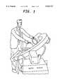
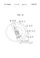
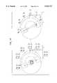
- the X-ray fluoroscopeis a widely available, low cost two-dimensional (2D) imaging equipment. Multiple views are possible, and typically this is done by turning the arm of a fluoroscope, such as a C-arm fluoroscope, an example of which is shown in FIG. 1a and FIG. 1b.
- the projection in a relatively parallel radiation pathwill cover a smaller portion of the detector surface, whereas in a small machine, the projection will be more divergent and will spread over a larger part of the detector surface and thereby interfere with the viewing of a region of interest.
- a method for calibrating an intra-operative X-ray system having an X-ray source and a detectorcomprises the steps of:
- the second position of the optical phantom in step 2-(B)is the same as the first position of the optical phantom in step 1-(c).
- the second position of the optical phantom in step 2-(B)is displaced from the first position of the optical phantom in step 1-(c).
- a method for calibrating an intra-operative X-ray systemincludes a step of determining spatial relationship parameters of the first position of the optical phantom relative to the second position of the optical phantom.
- apparatus for calibrating an intra-operative X-ray system having an X-ray source and a detectorcomprises:
- an optical cameraassociated with the detector
- an optical phantomplaced within a field of view of the optical cameras; and apparatus for computing a respective projection matrix from an image provided by any of the X-ray source and detector, and the optical cameras.
- a method for calibrating an intra-operative X-ray having an X-ray source and a detector system during a rotational run around a patientcomprises the steps of: beginning at a starting position and taking a radiographic image of an X-ray phantom from a first spatial position and taking respective optical images of an optical phantom from respective second and third spatial positions, the first and second spatial positions being in fixed relationship relative to the first spatial position, wherein the optical and X-ray phantoms are in fixed spatial relationship to one another; and deriving and storing respective projection matrices from the images.
- the stepsare repeated up to an end position of the run.
- the stepsare performed without a patient being present.
- a method for calibrating an intra-operative X-raycomprises the following steps with a patient being present: beginning at the starting position and taking respective optical images of the optical phantom from the first and second spatial positions in fixed relationship relative to the first spatial position; deriving respective projection matrices from the images; and calculating an X-ray projection matrix from the projection matrices.
- the steps performed with the patient being presentare performed without the X-ray phantom being present.
- apparatus for calibrating an intra-operative X-ray system having an X-ray source and a detectorincludes an optical camera associated with the X-ray source includes an optical camera associated with the detector; an X-ray phantom placed within a field of view of the X-ray system during an off-line process; an optical phantom placed within a field of view of the optical cameras during the off-line process as well as the on-line process (called the patient run); and apparatus for computing a respective projection matrix from an image provided by any of the X-ray source and detector, and the optical cameras.
- the relative motion of the apparatus between the off-line and on-line processis computed using the projection matrices characterizing the imaging geometry of the optical cameras. This information leads us to the modification of the off-line estimation of X-ray imaging geometry and to the characterization of its on line imaging geometry.
- a method for calibrating an intra-operative X-ray having an X-ray source and a detector system during a rotational run around a patientcomprising the steps of: beginning at a starting position and taking a radiographic image of an X-ray phantom from a first spatial position and taking respective optical images of an optical phantom from respective second and third spatial positions, the first and second spatial positions being in known relationship relative to the first spatial position, wherein the optical and X-ray phantoms are in known spatial relationship to one another; and deriving and storing respective projection matrices from the images.
- a method for calibrating an intra-operative X-raycomprises the following steps with a patient being present: beginning at the starting position and taking respective optical images of the optical phantom from the first and second spatial positions in known relationship relative to the first spatial position; deriving respective projection matrices from the images; calculating an X-ray projection matrix from the projection matrices and from the known relationships recited in claim 23.
- FIGS. 1A and Bshow a mobile intra-operative X-ray system showing the position of an X-ray source s and a detector plane d;
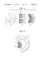
- FIG. 2shows cameras mounted on an X-ray C-arm in accordance with the invention
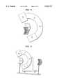
- FIGS. 3-6show various phantom arrangements in accordance with the invention.
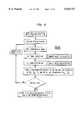
- FIGS. 7 and 9show flow charts helpful to a fuller understanding of the invention.
- FIGS. 8 and 10show diagrammatic representations of an estimation of projection matrices in accordance with the invention.
- FIG. 11shows a diagrammatic representation of a computation of relative motion between two sequences in accordance with the invention.
- FIG. 12shows a diagrammatic representation of a computation of relative motion between two cameras in accordance with the invention
- FIG. 13shows a diagrammatic representation of an estimation of a projection matrix in accordance with the invention.
- FIG. 14shows a diagrammatic representation of a method in accordance with the invention.
- optical cameras 22 of an X-ray unit 20are attached to the mobile C-arm in spatially fixed relationship thereto.
- the number of cameras to be usedis determined by the requirement of attaching a camera to each moving part of the X-ray system which plays a role in the geometrical configuration of the imaging process. For example, if the X-ray source and the detector were capable of independent motion, a camera is attached to each.
- the spatial relationship between the cameras and the X-ray imaging portions of the apparatusare primarily determined by the C-arm structure acting as unit, rather than by the support bearings and the frame or trunnion parts. Accordingly, this spatial relationship is sufficiently stable that it can be depended upon not to vary significantly over a certain period of use.
- a registration procedureis first carried out, in which an "off-line" calibration, without a patient being present, is performed, that is, one or more static pictures are taken by each camera and, at the same time, an X-ray radiographic picture is taken from an intelligent phantom with multiple characteristics. See FIG. 4.
- the exemplary phantom shown in FIG. 3comprises two parts: one part 30 is adapted to the X-ray imaging modality, and the other part 32 is adapted to the optical cameras.
- Markerssuch as steel balls 31 or other elements with a high X-ray absorption coefficient, are utilized in an X-ray target for the X-ray picture.
- Optical targets 33exhibiting easily read, well-defined patterns printed on X-ray-transparent material are provided for the optical cameras.
- the illustrative example of FIG. 3not especially adapted to any particular imaging geometry.
- the calibration phantom for the optical camerascan be one of a number of readily available materials selected for X-ray transparency and compatibility with an operating room environment.
- the mechanically coupled camera imaging system and the X-ray imaging systemare then calibrated to the same world coordinate system. Owing to the stability of the relationship between the camera and X-ray imaging systems, a transformation from the camera's coordinate system and the X-ray imaging system coordinates is accurately and dependably computed.
- the respective calibration phantoms in accordance with the inventiondo not have to be superimposed: They need only have a well-defined position relative to each other. This is illustrated by examples shown in FIGS. 5 and 6.
- FIG. 5shows that the respective phantoms are juxtaposed and
- FIG. 6shows that they are relatively spaced wide apart.
- the cameras and the X-ray systemare calibrated, it is not necessary to have the same phantoms in the operating room, where the patient is present. Because the X-ray/optical camera relationship has been defined and recorded, only a simple optical phantom is now needed for the optical cameras.
- the optical cameras in accordance with the inventiondo not necessarily have to have the patient in view or even the patient's bed: they can look away from that direction and still serve their intended purpose.
- the off-line calibration phantomis somewhat more complicated but, since it is only required occasionally for the registration procedure at which time, the patient being absent, there is generally no difficulty with the space and time needed for the off-line calibration.
- the motion of the cameras and/or associated projection matricesis determined and, utilizing the results obtained in the off-line calibration procedure, the parameters of the moving X-ray system are deducted.
- An example of off-line X-ray/cameras calibration in this caseis illustrated by the Flowchart in FIG. 7.
- Initial off-line calibrationThe C-arm is put through a motion resembling as closely as possible the motion it is expected to have during the patient run.
- Two calibration phantomsare located in the field of view.
- the first calibration phantomcomprises a set of markers intended to be clearly apparent on the X-ray image, such as a set of steel balls, preferably in a matrix carrier which is itself relatively transparent to X-rays.
- the second calibration phantomexhibits visual patterns which can be well detected, identified, and precisely located on the images taken by the optical cameras.
- the optical camerasare in the form of charge coupled device (CCD) optical wavelength cameras, though this is by no means essential.
- CCDcharge coupled device
- On-line calibrationonly optical phantoms are utilized during the patient run. No X-ray marker or phantom is used, in order to provide as much unobstructed viewing as possible for the operating physician.
- the optical phantomscan be placed in respective new positions, if this is desirable because it is more appropriate for the actual medical procedure or intervention to be performed. It is however necessary that these new positions for the optical phantoms be accurately defined with respect to the respective phantom positions that were utilized during the off-line calibration process. This relationship is purely geometric/mechanical and can be readily established, particularly since the whole of such a procedure is carried out with no patient present and before any on-line calibration takes place.
- FIG. 9illustrates an example of the on-line calibration process.
- FIG. 10illustrates the nature of the problem to be solved during the on-line calibration process.
- the patternshould be composed of parts opaque to the X-ray such as steel balls, while in the case of imaging by optical cameras these are visual patterns such as precisely drawn circles in color, or in black and white.
- parameters relating to the camera attached by the X-ray sourceare designated by “sc” (source camera) and parameters relating to the camera attached by the detector plane are designated by “dc” (detector camera).
- the details of the motion estimationare as follows, showing the direct computation of motion from projection matrices.
- the present mathematical methodallows computation of the motion of the imaging device using the 3 ⁇ 4 projection matrices P i , and P j , computed before and after a movement of the imaging device.
- the projection matrixcan be written in terms of a rotation matrix R defining the orientation of the camera, a translational vector T, and a upper triangular matrix A defining the camera intrinsic parameters (see the book of O. D. Faugeras referenced below).
- the motion of the C-armcan be also computed without the decompostion of the projection matrices.
- the distortion correction processwhich precedes the calibration measurement, automatically forces the imaging parameters to stay constant.
- P i and P jare the projection matrices obtained at two arbitrary position of the C-arm.
- the motion of the C-arm (R(i,j), T(i,j)), and the two projection matricessatisfy the following equation: ##EQU1## C-arm motion can therefore be directly computed:
- the matrix R(i,j)is a rotation matrix. This means that the nine unknowns of the matrix R(i,j) are non-linear functions of the three rotation parameters.
- the quarternion representation of the rotation matricesis used in order to reduce the number of unknowns and get accurate results.
- a quarternioncan be considered as a pair ⁇ , ⁇ !, where ⁇ is a real number and ⁇ a three-dimensional vector.
- a rotation of angle ⁇ around the axis ucan then represented by the quarternion: ##EQU3##
- Equation (3)can then be restated as: ##EQU8## where ##EQU9## S is a symmetric matrix and for each constant ⁇ ( ⁇ 0) the solution to this problem is the eigenvector q min s associated with the smallest eigenvalue of S. We however show that the eigenvectors of the matrix S are independent of ⁇ ( ⁇ 0). We also show that the eigenvector associated to the smallest eigenvalue stays the same when ⁇ ( ⁇ 0) varies.
- FIG. 12shows how the respective motion of each of the optical cameras is used to find their relative motion.
- a simple pinhole modelis used for modelling both the X-ray imaging geometry and the imaging geometry of CCD optical cameras.
- Such simple modellinghas different interpretations in these two cases.
- One differenceis that if the imaging plane of an optical camera is rotated, this will not change the optical axis of the camera which is defined by the lens. Therefore the same pinhole model is kept for the projection geometry and this change is taken account of by changing the intrinsic parameters or by a so-called image warping.
- the optical axis of the pinhole modelcan be defined by a perpendicular dropped from the source on to the detector plane. Therefore a small rotation of the detector plane can be considered as being equivalent to a global rotation of the whole camera and a rotation can be applied to the pinhole model so as to arrive at a new source/detector geometry.
- Relative translation between the X-ray source and the detector as computed from the relative motion of their associated optical camerasalso changes the intrinsic image parameters. This cannot be modeled through a global motion of the pinhole model of the X-ray imaging geometry. This motion can be compensated by horizontal and vertical shifts of the image followed by a change of scale. The change in scale is however believed to be negligibly small and thus does not have a measurable effect on image formation. The image correction does use only the horizontal and vertical shift.
- the symbol " ⁇ "is used in Figure K for emphasis.
- Figure Kshows how the projection matrices are estimated during the patient run.
- an off-line calibration patternincludes the on-line optical phantoms.
- FIG. 14shows one possible arrangement. It is understood that data storage and processing can be performed by a computer.
Landscapes
- Health & Medical Sciences (AREA)
- Life Sciences & Earth Sciences (AREA)
- Medical Informatics (AREA)
- Engineering & Computer Science (AREA)
- Radiology & Medical Imaging (AREA)
- Biomedical Technology (AREA)
- Biophysics (AREA)
- Nuclear Medicine, Radiotherapy & Molecular Imaging (AREA)
- Optics & Photonics (AREA)
- Pathology (AREA)
- Physics & Mathematics (AREA)
- High Energy & Nuclear Physics (AREA)
- Heart & Thoracic Surgery (AREA)
- Molecular Biology (AREA)
- Surgery (AREA)
- Animal Behavior & Ethology (AREA)
- General Health & Medical Sciences (AREA)
- Public Health (AREA)
- Veterinary Medicine (AREA)
- Apparatus For Radiation Diagnosis (AREA)
Abstract
Description
The present invention relates to X-ray systems and, more particularly, to the calibration of intra-operative X-ray systems.
The X-ray fluoroscope is a widely available, low cost two-dimensional (2D) imaging equipment. Multiple views are possible, and typically this is done by turning the arm of a fluoroscope, such as a C-arm fluoroscope, an example of which is shown in FIG. 1a and FIG. 1b.
Particular problems arise in the calibration of mobile intra-operative X-ray systems in the case where 3D reconstruction is to be performed. In the prior art, simple systems such as a mobile C-arm system have not generally been utilized for 3D reconstruction. In order to do a 3D reconstruction, the X-ray projection geometry needs typically to be characterized during the patient run. Such systems are generally relatively inexpensively constructed and typically lack the required stability and reproducibility. Therefore, the calibration needs to be done each time during the patient run since there is insufficient repeatability to apply simply the results of an off-line calibration.
The definitions and constraints involved in this type of application render the use of a calibration phantom X-ray operation impracticable. Thus, use of a phantom of X-ray opaque material is not practical because the phantom will interfere with the region of interest being viewed by the physician. If a calibration ring is used in conjunction with a limited region of interest such as the brain it may be used on an adjacent body part, such as the neck, without interfering with the part of interest, whereas in the case of a major body part such as the torso, this is no longer practicable.
Furthermore, if a calibration ring is used in a large machine, the projection in a relatively parallel radiation path will cover a smaller portion of the detector surface, whereas in a small machine, the projection will be more divergent and will spread over a larger part of the detector surface and thereby interfere with the viewing of a region of interest.
In the event that sufficient stability exists to provide repeatability between two consecutive runs, one with the calibration device and the patient and a second run with only the patient, the requirement of exposing the patient to a double dosage of radiation is herein recognized as not being acceptable.
In accordance with an aspect of the invention, a method for calibrating an intra-operative X-ray system having an X-ray source and a detector, the method comprises the steps of:
(1) performing an off-line process comprising:
(a) initializing the X-ray system into an arbitrary position,
(b) placing into a position an X-ray phantom,
(c) placing into a first position an optical phantom,
(d) taking a radiographic image,
(e) taking an optical image by a camera associated with the X-ray source,
(f) taking an optical image by a camera associated with the detector; and
(2) performing an on-line process comprising:
(A) initializing the X-ray system into a position,
(B) placing into a second position the optical phantom,
(C) taking a radiographic image,
(D) taking an optical image by a camera associated with the X-ray source,
(E) taking an optical image by a camera associated with the detector.
(3) combining information from the off-line optical images and X-ray image and the on-line optical images so as to derive a projection matrix for use in an image reconstruction process using the on-line X-ray image.
In accordance with an aspect of the invention, the second position of the optical phantom in step 2-(B) is the same as the first position of the optical phantom in step 1-(c).
In accordance with an aspect of the invention, the second position of the optical phantom in step 2-(B) is displaced from the first position of the optical phantom in step 1-(c).
In accordance with an aspect of the invention, a method for calibrating an intra-operative X-ray system includes a step of determining spatial relationship parameters of the first position of the optical phantom relative to the second position of the optical phantom.
In accordance with an aspect of the invention, apparatus for calibrating an intra-operative X-ray system having an X-ray source and a detector comprises:
an optical camera associated with the X-ray source;
an optical camera associated with the detector;
an X-ray phantom placed within a field of view of the X-ray system;
an optical phantom placed within a field of view of the optical cameras; and apparatus for computing a respective projection matrix from an image provided by any of the X-ray source and detector, and the optical cameras.
In accordance with an aspect of the invention, a method for calibrating an intra-operative X-ray having an X-ray source and a detector system during a rotational run around a patient, comprises the steps of: beginning at a starting position and taking a radiographic image of an X-ray phantom from a first spatial position and taking respective optical images of an optical phantom from respective second and third spatial positions, the first and second spatial positions being in fixed relationship relative to the first spatial position, wherein the optical and X-ray phantoms are in fixed spatial relationship to one another; and deriving and storing respective projection matrices from the images.
In accordance with an aspect of the invention, the steps are repeated up to an end position of the run.
In accordance with an aspect of the invention, the steps are performed without a patient being present.
In accordance with an aspect of the invention, a method for calibrating an intra-operative X-ray comprises the following steps with a patient being present: beginning at the starting position and taking respective optical images of the optical phantom from the first and second spatial positions in fixed relationship relative to the first spatial position; deriving respective projection matrices from the images; and calculating an X-ray projection matrix from the projection matrices.
In accordance with an aspect of the invention, the steps performed with the patient being present are performed without the X-ray phantom being present.
In accordance with an aspect of the invention, apparatus for calibrating an intra-operative X-ray system having an X-ray source and a detector includes an optical camera associated with the X-ray source includes an optical camera associated with the detector; an X-ray phantom placed within a field of view of the X-ray system during an off-line process; an optical phantom placed within a field of view of the optical cameras during the off-line process as well as the on-line process (called the patient run); and apparatus for computing a respective projection matrix from an image provided by any of the X-ray source and detector, and the optical cameras. A method to obtain the projection matrices characterizing the X-ray imaging geometry during the patient run, using the projection matrices associated to X-ray geometry as well as the optical cameras computed during an off-line process, and the projection matrices associated to the optical cameras during the patient run. The relative motion of the apparatus between the off-line and on-line process is computed using the projection matrices characterizing the imaging geometry of the optical cameras. This information leads us to the modification of the off-line estimation of X-ray imaging geometry and to the characterization of its on line imaging geometry.
In accordance with an aspect of the invention, a method for calibrating an intra-operative X-ray having an X-ray source and a detector system during a rotational run around a patient, the method comprising the steps of: beginning at a starting position and taking a radiographic image of an X-ray phantom from a first spatial position and taking respective optical images of an optical phantom from respective second and third spatial positions, the first and second spatial positions being in known relationship relative to the first spatial position, wherein the optical and X-ray phantoms are in known spatial relationship to one another; and deriving and storing respective projection matrices from the images.
In accordance with an aspect of the invention, a method for calibrating an intra-operative X-ray comprises the following steps with a patient being present: beginning at the starting position and taking respective optical images of the optical phantom from the first and second spatial positions in known relationship relative to the first spatial position; deriving respective projection matrices from the images; calculating an X-ray projection matrix from the projection matrices and from the known relationships recited in claim 23.
The invention will be more fully understood from the detailed description of preferred embodiments which follows, in conjunction with the drawing, in which
FIGS. 1A and B show a mobile intra-operative X-ray system showing the position of an X-ray source s and a detector plane d;
FIG. 2 shows cameras mounted on an X-ray C-arm in accordance with the invention;
FIGS. 3-6 show various phantom arrangements in accordance with the invention;
FIGS. 7 and 9 show flow charts helpful to a fuller understanding of the invention;
FIGS. 8 and 10 show diagrammatic representations of an estimation of projection matrices in accordance with the invention;
FIG. 11 shows a diagrammatic representation of a computation of relative motion between two sequences in accordance with the invention;
FIG. 12 shows a diagrammatic representation of a computation of relative motion between two cameras in accordance with the invention;
FIG. 13 shows a diagrammatic representation of an estimation of a projection matrix in accordance with the invention; and
FIG. 14 shows a diagrammatic representation of a method in accordance with the invention.
In accordance with an embodiment of the invention shown in FIG. 2,optical cameras 22 of anX-ray unit 20 are attached to the mobile C-arm in spatially fixed relationship thereto. The number of cameras to be used is determined by the requirement of attaching a camera to each moving part of the X-ray system which plays a role in the geometrical configuration of the imaging process. For example, if the X-ray source and the detector were capable of independent motion, a camera is attached to each.
The spatial relationship between the cameras and the X-ray imaging portions of the apparatus are primarily determined by the C-arm structure acting as unit, rather than by the support bearings and the frame or trunnion parts. Accordingly, this spatial relationship is sufficiently stable that it can be depended upon not to vary significantly over a certain period of use.
In accordance with an embodiment of the invention, a registration procedure is first carried out, in which an "off-line" calibration, without a patient being present, is performed, that is, one or more static pictures are taken by each camera and, at the same time, an X-ray radiographic picture is taken from an intelligent phantom with multiple characteristics. See FIG. 4.
The exemplary phantom shown in FIG. 3 comprises two parts: onepart 30 is adapted to the X-ray imaging modality, and theother part 32 is adapted to the optical cameras. Markers, such assteel balls 31 or other elements with a high X-ray absorption coefficient, are utilized in an X-ray target for the X-ray picture.Optical targets 33, exhibiting easily read, well-defined patterns printed on X-ray-transparent material are provided for the optical cameras. The illustrative example of FIG. 3 not especially adapted to any particular imaging geometry. The calibration phantom for the optical cameras can be one of a number of readily available materials selected for X-ray transparency and compatibility with an operating room environment.
The mechanically coupled camera imaging system and the X-ray imaging system, as shown in FIG. 4, for example, are then calibrated to the same world coordinate system. Owing to the stability of the relationship between the camera and X-ray imaging systems, a transformation from the camera's coordinate system and the X-ray imaging system coordinates is accurately and dependably computed.
It is noted that the respective calibration phantoms in accordance with the invention, one for the cameras and one for the X-ray, do not have to be superimposed: They need only have a well-defined position relative to each other. This is illustrated by examples shown in FIGS. 5 and 6. FIG. 5 shows that the respective phantoms are juxtaposed and FIG. 6 shows that they are relatively spaced wide apart. Furthermore, once the cameras and the X-ray system are calibrated, it is not necessary to have the same phantoms in the operating room, where the patient is present. Because the X-ray/optical camera relationship has been defined and recorded, only a simple optical phantom is now needed for the optical cameras.
It is particularly noted that the optical cameras in accordance with the invention do not necessarily have to have the patient in view or even the patient's bed: they can look away from that direction and still serve their intended purpose. In this case, the off-line calibration phantom is somewhat more complicated but, since it is only required occasionally for the registration procedure at which time, the patient being absent, there is generally no difficulty with the space and time needed for the off-line calibration.
The motion of the cameras and/or associated projection matrices is determined and, utilizing the results obtained in the off-line calibration procedure, the parameters of the moving X-ray system are deducted. An example of off-line X-ray/cameras calibration in this case is illustrated by the Flowchart in FIG. 7.
The steps of the method in accordance with the invention can be stated as follows.
Initial off-line calibration: The C-arm is put through a motion resembling as closely as possible the motion it is expected to have during the patient run. Two calibration phantoms are located in the field of view. The first calibration phantom comprises a set of markers intended to be clearly apparent on the X-ray image, such as a set of steel balls, preferably in a matrix carrier which is itself relatively transparent to X-rays.
The second calibration phantom exhibits visual patterns which can be well detected, identified, and precisely located on the images taken by the optical cameras. Conveniently, the optical cameras are in the form of charge coupled device (CCD) optical wavelength cameras, though this is by no means essential.
The correspondence found between three dimensional (3D) model points on the optical calibration phantoms and their X-ray images, as well as their CCD camera images is utilized to estimate three sets of projection matrices, defining the projection geometry of the X-ray equipment and of the CCD cameras. This initial off-line calibration process is found in FIG. 8.
On-line calibration: only optical phantoms are utilized during the patient run. No X-ray marker or phantom is used, in order to provide as much unobstructed viewing as possible for the operating physician. Optionally, the optical phantoms can be placed in respective new positions, if this is desirable because it is more appropriate for the actual medical procedure or intervention to be performed. It is however necessary that these new positions for the optical phantoms be accurately defined with respect to the respective phantom positions that were utilized during the off-line calibration process. This relationship is purely geometric/mechanical and can be readily established, particularly since the whole of such a procedure is carried out with no patient present and before any on-line calibration takes place.
During the patient run, a computation is carried out of the projection geometry of the CCD cameras and the X-ray projection geometry is deducted. The flowchart of FIG. 9 illustrates an example of the on-line calibration process. FIG. 10 illustrates the nature of the problem to be solved during the on-line calibration process.
In order to estimate the patient run X-ray projection matrices, first the relative motion of each optical camera between the off-line calibration and the patient run is computed. See FIG. 11.
In order to compute the projection matrix from the image of a calibration phantom, known patterns on the calibration phantom are automatically detected on the image. The correspondences between these patterns and the 3D model of the calibration phantom is then established. This is done by choosing the patterns such that their images can be uniquely identified. Once the correspondences between points on the model, such as the centroid of a pattern, and their images are established, the projection matrix is computed by solving the homogeneous system of equations P*Mi=λi*mi, i=1 . . . N, for the elements of the 3×4 projection matrix P. In this equation N is then number of point correspondences, Mi, i=1 . . . N, are the homogeneous coordinates of N 3D points on the model, and mi, i=1 . . . N, the homogeneous coordinates of their corresponding image points. In the case of radiographic imaging process the pattern should be composed of parts opaque to the X-ray such as steel balls, while in the case of imaging by optical cameras these are visual patterns such as precisely drawn circles in color, or in black and white.
In the following, parameters relating to the camera attached by the X-ray source are designated by "sc" (source camera) and parameters relating to the camera attached by the detector plane are designated by "dc" (detector camera).
The details of the motion estimation are as follows, showing the direct computation of motion from projection matrices. The present mathematical method allows computation of the motion of the imaging device using the 3×4 projection matrices Pi, and Pj, computed before and after a movement of the imaging device.
The 3×3 matrix p13 and the 3-D vector p4 are defined such that P= p13 p4!. The projection matrix can be written in terms of a rotation matrix R defining the orientation of the camera, a translational vector T, and a upper triangular matrix A defining the camera intrinsic parameters (see the book of O. D. Faugeras referenced below). Thus, p13=AR and p4=AT.
If the imaging parameters stay constant during the C-arm motion, it is herein shown that the motion of the C-arm can be also computed without the decompostion of the projection matrices. In the application particular to the described embodiment of the invention, the distortion correction process, which precedes the calibration measurement, automatically forces the imaging parameters to stay constant. If Pi and Pj are the projection matrices obtained at two arbitrary position of the C-arm. The motion of the C-arm (R(i,j), T(i,j)), and the two projection matrices satisfy the following equation: ##EQU1## C-arm motion can therefore be directly computed:
R.sub.(i,j) =κp.sub.13.sup.i.spsp.-1 p.sub.13.sup.j and T.sub.(i,j) =p.sub.13.sup.i.spsp.-1 (κp.sub.4.sup.j -p.sub.r.sup.i)
There are two main difficulties for accurately computing the unknowns R(i,j), T(i,j) and κ. The first one is the fact that the matrix R(i,j) is a rotation matrix. This means that the nine unknowns of the matrix R(i,j) are non-linear functions of the three rotation parameters. The quarternion representation of the rotation matrices is used in order to reduce the number of unknowns and get accurate results. The quarternion has been used in the past in order to solve problems of the form Rv=v'=v', where v and v' are known three dimensional vectors. The second problem here is that the unknown scalar κ makes our equations of the form: Rv=κv'. It is however herein shown that the quarternion representation can still be used in order to accurately compute the rotation matrix R.
It is desired to solve the algebraic equation:
R.sub.(i,j) p.sub.13.sup.i =κp.sub.13.sup.j
in order to recover the rotation matrix R(i,j) and the scale factor κ. Note that here R(i,j) is the transposed of previously defined p13 the left 3×3 block of the projection matrice. For the simplicity the transposed sign is not utilized. The mathematical equations have exactly the same forms. This expression can be written as:
R.sub.(i,j) p.sub.1.sup.i =κp.sub.1.sup.u
R.sub.(i,j) p.sub.2.sup.i =κp.sub.2.sup.u
R.sub.(i,j) p.sub.3.sup.i =κp.sub.3.sup.u
where pki and pku and the kth columns of the matrices p13i and p13j. The solution is then given by the rotation matrix which minimizes the following criterion: ##EQU2## Quarternion representation of rotation matrix has been used to solve this minimization problem where κ=1, f.g. see 1!. Since similar equations are herein used, there follows a brief definition of define quarternion q, and multiplication x of two quarternions q and q'.
A quarternion can be considered as a pair α,λ!, where α is a real number and λ a three-dimensional vector. A rotation of angle θ around the axis u can then represented by the quarternion: ##EQU3##
The multiplication x of two quarternions q and q' is defined as follows:
q×q'= αα'-λ.λ', αλ'+α'λ+λΛλ'!
where Λ is the operator for three dimensional crossproduct. The multiplication x is associative but not commutative. The conjugate and the magnitude of a quarternion q are defined as follows:
q= α,-λ!
∥q∥.sup.2 =q×q= α.sup.2 +∥λ∥.sup.2,0= ∥q∥.sup.2,0!
Note that the scalar value a is here identified with the quarternion α,0!.
The rotation matrix R represented by a unit quarternion q= α,λ! can be written as: ##EQU4## It is now important to note that applying the rotation R to a three-dimensional vector v, Rv, can be identified as the product of quarternions:
Rv=q×v×q
Note that the three-dimensional vector v is here identified with thequarternion 0,v!. Now we can restate the minimization problem of (2) in quarternion notation as: ##EQU5## By multiplying each term of the above equation with ∥q∥2, we get: ##EQU6## There exists a matrix Sk such that:
p.sub.k.sup.i ×q-κq×p.sub.k.sup.j =S.sub.k q
where: ##EQU7## Equation (3) can then be restated as: ##EQU8## where ##EQU9## S is a symmetric matrix and for each constant κ(≠0) the solution to this problem is the eigenvector qmins associated with the smallest eigenvalue of S. We however show that the eigenvectors of the matrix S are independent of κ(≠0). We also show that the eigenvector associated to the smallest eigenvalue stays the same when κ(≠0) varies.
The rotation matrix R(i,j), and the scalar factor κ are then easily deducted.
Looking more closely at ##EQU10## where
a.sub.k =(κp.sub.k.sup.u -p.sub.k.sup.i).sup.T (κp.sub.k.sup.j -p.sub.k.sup.i ()
and
b.sub.k =M(κp.sub.k.sup.u -p.sub.k.sup.i)
and
C.sub.k =(κp.sub.k.sup.u -p.sub.k.sup.i)(κp.sub.k.sup.u -p.sub.k.sup.i).sup.T -M.sup.2
where M=(κpkj≈ +pki). we then have:
a.sub.k =κ.sup.2 ∥p.sub.k.sup.j ∥.sup.2 +∥p.sub.k.sup.i ∥.sup.2 -2κp.sub.k.sup.j.spsp.T p.sub.k.sup.i
and
b.sub.k =(κp.sub.k.sup.j +p.sub.k.sup.i) (κp.sub.k.sup.j -p.sub.k.sup.i)=(2κ(p.sub.k.sup.i p.sub.k.sup.j)
and ##EQU11## We can therefore write:
S.sub.k.sup.t S.sub.k =α.sub.k.sup.2 I.sub.4×4 -2κQ.sub.k(5)
where αk =∥pki +κpkj ∥, and ##EQU12## now, let us suppose λI, I=1 . . . 4, are the four eigenvalues of the matrix S and vi, I=1 . . . 4, their associated eigenvectors. We have Svi=λivi. Using equation 5 we have: ##EQU13## This results in (κ≠0): ##EQU14## This result shows that the eigenvectors of the matrix S are independent of κ(≠0). This also shows that the eigenvector associated to the smallest eigenvalue stays the same when κ(≠0) varies. The rotation matrix R(i,j), and the scalar factor κ are then easily deducted. Once the rotation matrix R(i,j) and the scale factor κ are computed, the translational vector T(i,j) is computed:
T.sub.(i,j) =p.sub.13.sup.i.spsp.-1 (κp.sub.4.sup.u -p.sub.4.sup.i)
Background material relative to the foregoing can be found in, for example, Z. Zhang and O. Faugeras. 3D Dynamic Scene Analysis: A Stereo Based Approach. Springer, Berlin, Heidelberg, 1992; and O. D. Faugeras. Three-Dimensional Computer Vision: A Geometric Viewpoint. MIT Press, Cambridge, Mass., 1993.
In the case where the system is mechanically stable and where its motion is perfectly reproducible, there should be no motion between the off-line and on-line projection matrices. In this case, in theory, all rotation matrices are 3×3 identity matrices and the translation vectors vanish. So long as this reproducibility is not achieved mechanically, these matrices help provide an estimate of the relative motion between the off-line and the on-line imaging geometry.
In the event the detector has well-known characteristics at each position, which is the case when using ASI (Amorphous Silicon) detectors rather than image intensifiers, the changes in the X-ray geometry are due to both the motion of the X-ray source and the detector plane. FIG. 12 shows how the respective motion of each of the optical cameras is used to find their relative motion.
Often a simple pinhole model is used for modelling both the X-ray imaging geometry and the imaging geometry of CCD optical cameras. Such simple modelling has different interpretations in these two cases. One difference is that if the imaging plane of an optical camera is rotated, this will not change the optical axis of the camera which is defined by the lens. Therefore the same pinhole model is kept for the projection geometry and this change is taken account of by changing the intrinsic parameters or by a so-called image warping. In the X-ray geometry there is no lens per se. The optical axis of the pinhole model can be defined by a perpendicular dropped from the source on to the detector plane. Therefore a small rotation of the detector plane can be considered as being equivalent to a global rotation of the whole camera and a rotation can be applied to the pinhole model so as to arrive at a new source/detector geometry.
Relative translation between the X-ray source and the detector as computed from the relative motion of their associated optical cameras also changes the intrinsic image parameters. This cannot be modeled through a global motion of the pinhole model of the X-ray imaging geometry. This motion can be compensated by horizontal and vertical shifts of the image followed by a change of scale. The change in scale is however believed to be negligibly small and thus does not have a measurable effect on image formation. The image correction does use only the horizontal and vertical shift. The symbol "˜" is used in Figure K for emphasis. Figure K shows how the projection matrices are estimated during the patient run.
It is also contemplated that an off-line calibration pattern includes the on-line optical phantoms. FIG. 14 shows one possible arrangement. It is understood that data storage and processing can be performed by a computer.
While the invention has been described by way of exemplary embodiments, it will be apparent to one of skill in the art to which it pertains that a number of changes and substitutions may be made without departing from the spirit of the invention. Such changes and substitutions are within the contemplation of the invention which is defined by the scope of the claims following.
Claims (30)
1. A method for calibrating an intra-operative X-ray system having an X-ray source and a detector, said method comprising the steps of:
(1) performing an off-line process comprising:
(a) initializing said X-ray system into an arbitrary position,
(b) placing into a position an X-ray phantom,
(c) placing into a first position an optical phantom,
(d) taking an off-line X-ray image,
(e) taking an optical image by a camera associated with said X-ray source,
(f) taking an off-line optical image by a camera associated with said detector; and
(2) performing an on-line process comprising:
(A) initializing said X-ray system into a position,
(B) placing into a second position said optical phantom,
(C) taking an on-line X-ray image,
(D) taking an on-line optical image by a camera associated with said X-ray source, and
(E) taking an optical image by a camera associated with said detector; and
(3) combining information from said off-line optical images and said off-line X-ray image and the on-line optical images so as to derive a projection matrix for use in an image reconstruction process using said on-line X-ray image.
2. A method for calibrating an intra-operative X-ray system as recited in claim 1, wherein said second position of said optical phantom in step 2-(B) is the same as said first position of said optical phantom in step 1-(c).
3. A method for calibrating an intra-operative X-ray system as recited in claim 1, wherein said second position of said optical phantom in step 2-(B) is displaced from said first position of said optical phantom in step 1-(c).
4. A method for calibrating an intra-operative X-ray system as recited in claim 3, including a step of determining spatial relationship parameters of said first position of said optical phantom relative to said second position of said optical phantom.
5. A method for calibrating an intra-operative X-ray system as recited in claim 4, wherein step (3) includes combining of said spatial relationship parameters of said first position of said optical phantom so as to derive said projection matrix for use in an image reconstruction process.
6. A method for calibrating an intra-operative X-ray system as recited in claim 1, including a step of utilizing said projection matrix so as to form a reconstructed image.
7. A method for calibrating an intra-operative X-ray having an X-ray source and a detector system, said method comprising the steps of:
(A) performing an off-line process comprising:
(a) initializing said X-ray system into an initial position, as closely as possible to its position when a patient is present,
(b) placing into position an X-ray phantom,
(c) placing into position an optical phantom,
(d) taking off-line, a radiographic image,
(e) computing and storing a projection matrix Px
(f) taking off-line, an optical image by a camera associated with said X-ray source,
(g) computing from said optical image and storing a projection matrix Psc
(h) taking off-line, an optical image by a camera associated with said detector, and
(i) computing from said optical image and storing a projection matrix Pdc ; and
(B) performing an on-line process comprising:
(1) placing into position an optical phantom,
(2) taking on-line, a radiographic image,
(3) taking on-line, an optical image by a camera associated with said X-ray source,
(4) computing from said optical image and storing a projection matrix psc
(5) taking on-line, an optical image by a camera associated with said detector,
(7) computing from said optical image and storing a projection matrix pdc, and
(8) calculating an X-ray projection matrix Px from said foregoing matrices Px, Psc, Pdc, psc, pdc.
8. A method for calibrating an intra-operative X-ray having an X-ray source and a detector system during a rotational run around the patient, said method comprising the steps of:
(A) performing an off-line process comprising:
(a) initializing said X-ray system into a starting position (i),
(b) placing into position an X-ray phantom,
(c) placing into position an optical phantom,
(d) taking off-line, a radiographic image,
(e) computing and storing a projection matrix Pxi
(f) taking off-line, an optical image by a camera associated with said X-ray source,
(g) computing from said optical image and storing a projection matrix Psci
(h) taking off-line, an optical image by a camera associated with said detector,
(i) computing from said optical image and storing a projection matrix Pdci
(j) rotating said X-ray system to the next position (i+1)
(k) repeating steps (d) through (j) unless the end position is reached; and
(B) performing an on-line process comprising:
(1) initializing said X-ray system into said starting position (i),
(2) placing into position an optical phantom,
(3) taking on-line, a radiographic image,
(4) taking on-line, an optical image by a camera associated with said X-ray source,
(5) computing from said optical image and storing a projection matrix psci
(6) taking on-line, an optical image by a camera associated with said detector,
(7) computing from said optical image and storing a projection matrix pdci
(8) calculating an X-ray projection matrix Pxi from said foregoing matrices Pxi, Psci, Pdci, psci, pdci ;
(9) rotating said X-ray system tp the next position (i+1),
(10) repeating (3) through (9) unless the end position is reached, and
(11) applying said projection matrices Pxi to an image reconstruction process.
9. Apparatus for calibrating an intra-operative X-ray system having an X-ray source and a detector, said apparatus comprising:
an optical camera associated with said X-ray source;
an optical camera associated with said detector;
an X-ray phantom placed within a field of view of said X-ray system;
an optical phantom placed within a field of view of said optical cameras; and
means for computing a respective projection matrix from an image provided by any of said X-ray source and detector, and said optical cameras.
10. Apparatus for calibrating an intra-operative X-ray system as recited in claim 8, wherein said optical camera associated with said X-ray source is mounted in fixed spatial relationship with and proximate said X-ray source.
11. Apparatus for calibrating an intra-operative X-ray system as recited in claim 9, wherein said optical camera associated with said detector is mounted in fixed spatial relationship with and proximate said detector.
12. Apparatus for calibrating an intra-operative X-ray system as recited in claim 10, wherein said X-ray phantom comprises X-ray opaque reference bodies supported in an X-ray transparent body.
13. Apparatus for calibrating an intra-operative X-ray system as recited in claim 11, wherein said optical phantom comprises visible reference marks formed on an X-ray transparent body.
14. Apparatus for calibrating an intra-operative X-ray system as recited in claim 12, including means for utilizing said respective projection matrices so as to form a reconstructed image.
15. A method for calibrating an intra-operative X-ray having an X-ray source and a detector system during a rotational run around a patient, said method comprising the steps of:
beginning at a starting position and taking a radiographic image of an X-ray phantom from a first spatial position and taking respective optical images of an optical phantom from respective second and third spatial positions, said first and second spatial positions being in fixed relationship relative to said first spatial position, wherein said optical and X-ray phantoms are in fixed spatial relationship to one another; and
deriving and storing respective projection matrices from said images.
16. A method for calibrating an intra-operative X-ray in accordance with claim 15 wherein said steps are repeated up to an end position of said run.
17. A method for calibrating an intra-operative X-ray in accordance with claim 16 wherein the steps recited in claim 8 are performed without a patient being present.
18. A method for calibrating an intra-operative X-ray in accordance with claim 17, comprising the following steps with a patient being present:
beginning at said starting position and taking respective optical images of said optical phantom from said first and second spatial positions in fixed relationship relative to said first spatial position;
deriving respective projection matrices from said images; and
calculating an X-ray projection matrix from said projection matrices.
19. A method for calibrating an intra-operative X-ray in accordance with claim 18 wherein said steps are performed without said X-ray phantom being present.
20. A method for calibrating an intra-operative X-ray in accordance with claim 19 wherein said steps are repeated up to an end position of said run.
21. A method for calibrating an intra-operative X-ray in accordance with claim 20 wherein an X-ray image is taken at each step.
22. A method for calibrating an intra-operative X-ray in accordance with claim 21 wherein said respective X-ray projection matrices for said steps are utilized for calibration of said X-ray image.
23. A method for calibrating an intra-operative X-ray having an X-ray source and a detector system during a rotational run around a patient, said method comprising the steps of:
beginning at a starting position and taking a radiographic image of an X-ray phantom from a first spatial position and taking respective optical images of an optical phantom from respective second and third spatial positions, said first and second spatial positions being in known relationship relative to said first spatial position, wherein said optical and X-ray phantoms are in known spatial relationship to one another; and
deriving and storing respective projection matrices from said images.
24. A method for calibrating an intra-operative X-ray in accordance with claim 23 wherein said steps are repeated up to an end position of said run.
25. A method for calibrating an intra-operative X-ray in accordance with claim 24 wherein the steps recited in claim 8 are performed without a patient being present.
26. A method for calibrating an intra-operative X-ray in accordance with claim 25, comprising the following steps with a patient being present:
beginning at said starting position and taking respective optical images of said optical phantom from said first and second spatial positions in known relationship relative to said first spatial position;
deriving respective projection matrices from said images; and
calculating an X-ray projection matrix from said projection matrices and from said known relationships recited in claim 23.
27. A method for calibrating an intra-operative X-ray in accordance with claim 26 wherein said steps are performed without said X-ray phantom being present.
28. A method for calibrating an intra-operative X-ray in accordance with claim 27 wherein said steps are repeated up to an end position of said run.
29. A method for calibrating an intra-operative X-ray in accordance with claim 28 wherein an X-ray image is taken at each step.
30. A method for calibrating an intra-operative X-ray in accordance with claim 29 wherein said respective X-ray projection matrices for said steps are utilized for calibration of said X-ray image.
Priority Applications (1)
| Application Number | Priority Date | Filing Date | Title |
|---|---|---|---|
| US08/940,923US5923727A (en) | 1997-09-30 | 1997-09-30 | Method and apparatus for calibrating an intra-operative X-ray system |
Applications Claiming Priority (1)
| Application Number | Priority Date | Filing Date | Title |
|---|---|---|---|
| US08/940,923US5923727A (en) | 1997-09-30 | 1997-09-30 | Method and apparatus for calibrating an intra-operative X-ray system |
Publications (1)
| Publication Number | Publication Date |
|---|---|
| US5923727Atrue US5923727A (en) | 1999-07-13 |
Family
ID=25475651
Family Applications (1)
| Application Number | Title | Priority Date | Filing Date |
|---|---|---|---|
| US08/940,923Expired - LifetimeUS5923727A (en) | 1997-09-30 | 1997-09-30 | Method and apparatus for calibrating an intra-operative X-ray system |
Country Status (1)
| Country | Link |
|---|---|
| US (1) | US5923727A (en) |
Cited By (108)
| Publication number | Priority date | Publication date | Assignee | Title |
|---|---|---|---|---|
| WO1999057699A1 (en)* | 1998-05-04 | 1999-11-11 | Advanced Research & Technology Institute | Aortic stent-graft calibration and training model |
| US6052611A (en)* | 1997-11-28 | 2000-04-18 | Picker International, Inc. | Frameless stereotactic tomographic scanner for image guided interventional procedures |
| US6050724A (en)* | 1997-01-31 | 2000-04-18 | U. S. Philips Corporation | Method of and device for position detection in X-ray imaging |
| JP2001061827A (en)* | 1999-08-03 | 2001-03-13 | Siemens Ag | Mobile X-ray apparatus and method for determining imaging position |
| DE19957133A1 (en)* | 1999-11-26 | 2001-06-07 | Siemens Ag | Production of an active transistor region on a substrate comprises producing a trenched doping region in the substrate, producing an epitaxial layer, forming a retrograde doping profile in the epitaxial layer and further processing |
| US6298109B1 (en)* | 1996-02-21 | 2001-10-02 | Lunar Corporation | X-ray imaging system |
| WO2001087136A3 (en)* | 2000-04-28 | 2002-02-28 | Visualization Technology | Fluoroscopic tracking and visualization system |
| DE10057023A1 (en)* | 2000-11-17 | 2002-06-06 | Siemens Ag | Method and appliance for identifying correct alignment of fractured bones by superimposition of templates on images of those bones |
| US6447163B1 (en)* | 1999-09-30 | 2002-09-10 | Siemens Corporate Research, Inc. | Method for aligning and superimposing X-ray and video images |
| US6461040B1 (en)* | 1998-11-12 | 2002-10-08 | Koninklijke Philips Electronics N.V. | Apparatus and method to correct for position errors in diagnostic imaging |
| US6470207B1 (en)* | 1999-03-23 | 2002-10-22 | Surgical Navigation Technologies, Inc. | Navigational guidance via computer-assisted fluoroscopic imaging |
| US20030014034A1 (en)* | 2001-03-22 | 2003-01-16 | Norbert Strobel | Method for detecting the three-dimensional position of a medical examination instrument introduced into a body region, particularly of a catheter introduced into a vessel |
| US6533454B1 (en)* | 1999-09-30 | 2003-03-18 | Bionx Implants Oy | Surgical system for tissue fixation |
| US20030088179A1 (en)* | 2000-04-28 | 2003-05-08 | Teresa Seeley | Fluoroscopic tracking and visualization system |
| US20030130576A1 (en)* | 2000-04-28 | 2003-07-10 | Teresa Seeley | Fluoroscopic tracking and visualization system |
| US20030163271A1 (en)* | 2002-02-25 | 2003-08-28 | Erik Chell | Method and apparatus for reconstruction calibration of detector position and source motion based on a multi-pin phantom |
| US20030163038A1 (en)* | 2002-02-28 | 2003-08-28 | Simon David A. | Method and apparatus for perspective inversion |
| US20030167142A1 (en)* | 2002-02-25 | 2003-09-04 | Erik Chell | Method and apparatus for reconstruction calibration of detector position and source motion based on a multi-pin phantom |
| EP1346689A3 (en)* | 2002-02-25 | 2003-12-03 | GE Medical Systems Global Technology Company LLC | Method and apparatus for controlling electron beam motion based on calibration information |
| US20040044496A1 (en)* | 2002-08-29 | 2004-03-04 | Olympus Optical Co., Ltd. | Calibration pattern unit |
| DE10317137A1 (en)* | 2003-04-14 | 2004-11-18 | Siemens Ag | X-ray apparatus with scanning support taking series of two-dimensional projections from object under investigation and includes three-dimensional sensor on carrier |
| DE10049103B4 (en)* | 1999-09-30 | 2005-01-27 | Siemens Corp. Research, Inc. | Device for overlaying X-ray and video images |
| US6892090B2 (en) | 2002-08-19 | 2005-05-10 | Surgical Navigation Technologies, Inc. | Method and apparatus for virtual endoscopy |
| US6920347B2 (en) | 2000-04-07 | 2005-07-19 | Surgical Navigation Technologies, Inc. | Trajectory storage apparatus and method for surgical navigation systems |
| US20050169510A1 (en)* | 2004-02-03 | 2005-08-04 | Zuhars Joel F. | Method and apparatus for instrument tracking on a scrolling series of 2D fluoroscopic images |
| US6968224B2 (en) | 1999-10-28 | 2005-11-22 | Surgical Navigation Technologies, Inc. | Method of detecting organ matter shift in a patient |
| US6990368B2 (en) | 2002-04-04 | 2006-01-24 | Surgical Navigation Technologies, Inc. | Method and apparatus for virtual digital subtraction angiography |
| US7007699B2 (en) | 1999-10-28 | 2006-03-07 | Surgical Navigation Technologies, Inc. | Surgical sensor |
| USRE39133E1 (en) | 1997-09-24 | 2006-06-13 | Surgical Navigation Technologies, Inc. | Percutaneous registration apparatus and method for use in computer-assisted surgical navigation |
| US7085400B1 (en) | 2000-06-14 | 2006-08-01 | Surgical Navigation Technologies, Inc. | System and method for image based sensor calibration |
| US7130676B2 (en) | 1998-08-20 | 2006-10-31 | Sofamor Danek Holdings, Inc. | Fluoroscopic image guided orthopaedic surgery system with intraoperative registration |
| US7174202B2 (en) | 1992-08-14 | 2007-02-06 | British Telecommunications | Medical navigation apparatus |
| US7217276B2 (en) | 1999-04-20 | 2007-05-15 | Surgical Navigational Technologies, Inc. | Instrument guidance method and system for image guided surgery |
| WO2007073988A1 (en)* | 2005-12-27 | 2007-07-05 | Siemens Aktiengesellschaft | Imaging system and method for preparing x-ray images and optical images |
| US7313430B2 (en) | 2003-08-28 | 2007-12-25 | Medtronic Navigation, Inc. | Method and apparatus for performing stereotactic surgery |
| US20080064952A1 (en)* | 2006-08-18 | 2008-03-13 | Dun Alex Li | Systems and methods for on-line marker-less camera calibration using a position tracking system |
| US7366562B2 (en) | 2003-10-17 | 2008-04-29 | Medtronic Navigation, Inc. | Method and apparatus for surgical navigation |
| US7542791B2 (en) | 2003-01-30 | 2009-06-02 | Medtronic Navigation, Inc. | Method and apparatus for preplanning a surgical procedure |
| EP2072012A1 (en)* | 2007-12-18 | 2009-06-24 | Siemens Aktiengesellschaft | Method for calibration of a camera augmented C-arm |
| USRE40852E1 (en) | 1995-06-14 | 2009-07-14 | Medtronic Navigation, Inc. | Method and system for navigating a catheter probe |
| US7567834B2 (en) | 2004-05-03 | 2009-07-28 | Medtronic Navigation, Inc. | Method and apparatus for implantation between two vertebral bodies |
| US7570791B2 (en) | 2003-04-25 | 2009-08-04 | Medtronic Navigation, Inc. | Method and apparatus for performing 2D to 3D registration |
| US7599730B2 (en) | 2002-11-19 | 2009-10-06 | Medtronic Navigation, Inc. | Navigation system for cardiac therapies |
| DE102008021836A1 (en) | 2008-04-30 | 2009-11-05 | Siemens Aktiengesellschaft | X-ray image recording system has X-ray radiation source, X-ray radiation detector for receiving X-ray of object and controlling and evaluating unit for driving X-ray radiation source and X-ray radiation detector |
| US7636595B2 (en) | 2004-10-28 | 2009-12-22 | Medtronic Navigation, Inc. | Method and apparatus for calibrating non-linear instruments |
| US7657300B2 (en) | 1999-10-28 | 2010-02-02 | Medtronic Navigation, Inc. | Registration of human anatomy integrated for electromagnetic localization |
| US7660623B2 (en) | 2003-01-30 | 2010-02-09 | Medtronic Navigation, Inc. | Six degree of freedom alignment display for medical procedures |
| US7697972B2 (en) | 2002-11-19 | 2010-04-13 | Medtronic Navigation, Inc. | Navigation system for cardiac therapies |
| US7763035B2 (en) | 1997-12-12 | 2010-07-27 | Medtronic Navigation, Inc. | Image guided spinal surgery guide, system and method for use thereof |
| US7797032B2 (en) | 1999-10-28 | 2010-09-14 | Medtronic Navigation, Inc. | Method and system for navigating a catheter probe in the presence of field-influencing objects |
| US20100246778A1 (en)* | 2009-03-24 | 2010-09-30 | Benno Heigl | Method for Calibrating the Position of a Laser Fan Beam Relative to the Projection Geometry of an X-Ray Device and X-Ray Device |
| US7835784B2 (en) | 2005-09-21 | 2010-11-16 | Medtronic Navigation, Inc. | Method and apparatus for positioning a reference frame |
| US7835778B2 (en) | 2003-10-16 | 2010-11-16 | Medtronic Navigation, Inc. | Method and apparatus for surgical navigation of a multiple piece construct for implantation |
| US7840253B2 (en) | 2003-10-17 | 2010-11-23 | Medtronic Navigation, Inc. | Method and apparatus for surgical navigation |
| US7881770B2 (en) | 2000-03-01 | 2011-02-01 | Medtronic Navigation, Inc. | Multiple cannula image guided tool for image guided procedures |
| US20110164721A1 (en)* | 2008-07-31 | 2011-07-07 | Fraunhofer-Gesellschaft Zur Forderung Der Angewandten Forschung E.V. | X-ray image recording system and x-ray recording method for recording image data with x-ray units for volume reconstruction |
| DE102010005633A1 (en) | 2010-01-25 | 2011-07-14 | Siemens Aktiengesellschaft, 80333 | X-ray device for creating 3D X-ray images of an examination subject |
| US20110188639A1 (en)* | 2007-07-12 | 2011-08-04 | Cooke T Derek V | Radiographic imaging apparatus |
| US20110191084A1 (en)* | 2007-07-12 | 2011-08-04 | Cooke T Derek V | Radiographic imaging method and apparatus |
| US7998062B2 (en) | 2004-03-29 | 2011-08-16 | Superdimension, Ltd. | Endoscope structures and techniques for navigating to a target in branched structure |
| US8074662B2 (en) | 1999-10-28 | 2011-12-13 | Medtronic Navigation, Inc. | Surgical communication and power system |
| US8112292B2 (en) | 2006-04-21 | 2012-02-07 | Medtronic Navigation, Inc. | Method and apparatus for optimizing a therapy |
| EP2178441A4 (en)* | 2007-07-10 | 2012-03-28 | T Derek V Cooke | Radiographic imaging method and apparatus |
| USRE43328E1 (en) | 1997-11-20 | 2012-04-24 | Medtronic Navigation, Inc | Image guided awl/tap/screwdriver |
| US8165658B2 (en) | 2008-09-26 | 2012-04-24 | Medtronic, Inc. | Method and apparatus for positioning a guide relative to a base |
| US8175681B2 (en) | 2008-12-16 | 2012-05-08 | Medtronic Navigation Inc. | Combination of electromagnetic and electropotential localization |
| US8239001B2 (en) | 2003-10-17 | 2012-08-07 | Medtronic Navigation, Inc. | Method and apparatus for surgical navigation |
| USRE43952E1 (en) | 1989-10-05 | 2013-01-29 | Medtronic Navigation, Inc. | Interactive system for local intervention inside a non-homogeneous structure |
| US8452068B2 (en) | 2008-06-06 | 2013-05-28 | Covidien Lp | Hybrid registration method |
| US8473032B2 (en) | 2008-06-03 | 2013-06-25 | Superdimension, Ltd. | Feature-based registration method |
| US8494613B2 (en) | 2009-08-31 | 2013-07-23 | Medtronic, Inc. | Combination localization system |
| US8494614B2 (en) | 2009-08-31 | 2013-07-23 | Regents Of The University Of Minnesota | Combination localization system |
| US8553839B2 (en) | 2008-12-11 | 2013-10-08 | Koninklijke Philips N.V. | System and method for generating images of a patient's interior and exterior |
| US8611984B2 (en) | 2009-04-08 | 2013-12-17 | Covidien Lp | Locatable catheter |
| US8644907B2 (en) | 1999-10-28 | 2014-02-04 | Medtronic Navigaton, Inc. | Method and apparatus for surgical navigation |
| US8660635B2 (en) | 2006-09-29 | 2014-02-25 | Medtronic, Inc. | Method and apparatus for optimizing a computer assisted surgical procedure |
| US8663088B2 (en) | 2003-09-15 | 2014-03-04 | Covidien Lp | System of accessories for use with bronchoscopes |
| US20140064456A1 (en)* | 2012-08-31 | 2014-03-06 | General Electric Company | Motion correction system and method for an x-ray tube |
| US8764725B2 (en) | 2004-02-09 | 2014-07-01 | Covidien Lp | Directional anchoring mechanism, method and applications thereof |
| US8905920B2 (en) | 2007-09-27 | 2014-12-09 | Covidien Lp | Bronchoscope adapter and method |
| US8932207B2 (en) | 2008-07-10 | 2015-01-13 | Covidien Lp | Integrated multi-functional endoscopic tool |
| US9055881B2 (en) | 2004-04-26 | 2015-06-16 | Super Dimension Ltd. | System and method for image-based alignment of an endoscope |
| US9168102B2 (en) | 2006-01-18 | 2015-10-27 | Medtronic Navigation, Inc. | Method and apparatus for providing a container to a sterile environment |
| US9575140B2 (en) | 2008-04-03 | 2017-02-21 | Covidien Lp | Magnetic interference detection system and method |
| EP3150124A1 (en)* | 2015-09-29 | 2017-04-05 | Technische Universität München | Apparatus and method for augmented visualization employing x-ray and optical data |
| WO2017072125A1 (en) | 2015-10-26 | 2017-05-04 | Surgiqual Institute | Rotary collimator for determining the position of an element provided with sensors in an x-ray imaging system |
| US9675424B2 (en) | 2001-06-04 | 2017-06-13 | Surgical Navigation Technologies, Inc. | Method for calibrating a navigation system |
| JP2019141193A (en)* | 2018-02-19 | 2019-08-29 | コニカミノルタ株式会社 | Radiographic system and console |
| US10418705B2 (en) | 2016-10-28 | 2019-09-17 | Covidien Lp | Electromagnetic navigation antenna assembly and electromagnetic navigation system including the same |
| EP2603767B1 (en)* | 2010-08-12 | 2019-09-25 | Beissbarth GmbH | Method for calibrating a measurement system and device for carrying out the method |
| US10426555B2 (en) | 2015-06-03 | 2019-10-01 | Covidien Lp | Medical instrument with sensor for use in a system and method for electromagnetic navigation |
| US10446931B2 (en) | 2016-10-28 | 2019-10-15 | Covidien Lp | Electromagnetic navigation antenna assembly and electromagnetic navigation system including the same |
| US10478254B2 (en) | 2016-05-16 | 2019-11-19 | Covidien Lp | System and method to access lung tissue |
| US10517505B2 (en) | 2016-10-28 | 2019-12-31 | Covidien Lp | Systems, methods, and computer-readable media for optimizing an electromagnetic navigation system |
| US10582834B2 (en) | 2010-06-15 | 2020-03-10 | Covidien Lp | Locatable expandable working channel and method |
| US10615500B2 (en) | 2016-10-28 | 2020-04-07 | Covidien Lp | System and method for designing electromagnetic navigation antenna assemblies |
| US10638952B2 (en) | 2016-10-28 | 2020-05-05 | Covidien Lp | Methods, systems, and computer-readable media for calibrating an electromagnetic navigation system |
| US10722311B2 (en) | 2016-10-28 | 2020-07-28 | Covidien Lp | System and method for identifying a location and/or an orientation of an electromagnetic sensor based on a map |
| US10751126B2 (en) | 2016-10-28 | 2020-08-25 | Covidien Lp | System and method for generating a map for electromagnetic navigation |
| US10792106B2 (en) | 2016-10-28 | 2020-10-06 | Covidien Lp | System for calibrating an electromagnetic navigation system |
| US10952593B2 (en) | 2014-06-10 | 2021-03-23 | Covidien Lp | Bronchoscope adapter |
| US11006914B2 (en) | 2015-10-28 | 2021-05-18 | Medtronic Navigation, Inc. | Apparatus and method for maintaining image quality while minimizing x-ray dosage of a patient |
| US11219489B2 (en) | 2017-10-31 | 2022-01-11 | Covidien Lp | Devices and systems for providing sensors in parallel with medical tools |
| US11308645B2 (en)* | 2017-05-12 | 2022-04-19 | The Board Of Trustees Of The Leland Stanford Junior University | Apparatus and method for wide-range optical tracking during medical imaging |
| US11331150B2 (en) | 1999-10-28 | 2022-05-17 | Medtronic Navigation, Inc. | Method and apparatus for surgical navigation |
| EP4201333A1 (en)* | 2021-12-22 | 2023-06-28 | Siemens Healthineers International AG | Universal phantom for calibration and verification of optical and radiation systems |
| US12089902B2 (en) | 2019-07-30 | 2024-09-17 | Coviden Lp | Cone beam and 3D fluoroscope lung navigation |
| CN119606536A (en)* | 2024-12-25 | 2025-03-14 | 合肥美亚光电技术股份有限公司 | Image processing method, C-arm machine, electronic device and medium for medical assistance |
Citations (4)
| Publication number | Priority date | Publication date | Assignee | Title |
|---|---|---|---|---|
| US5315630A (en)* | 1992-03-11 | 1994-05-24 | Bodenseewerk Geratetechnik Gmbh | Positioning device in medical apparatus |
| US5446548A (en)* | 1993-10-08 | 1995-08-29 | Siemens Medical Systems, Inc. | Patient positioning and monitoring system |
| US5588430A (en)* | 1995-02-14 | 1996-12-31 | University Of Florida Research Foundation, Inc. | Repeat fixation for frameless stereotactic procedure |
| US5772594A (en)* | 1995-10-17 | 1998-06-30 | Barrick; Earl F. | Fluoroscopic image guided orthopaedic surgery system with intraoperative registration |
- 1997
- 1997-09-30USUS08/940,923patent/US5923727A/ennot_activeExpired - Lifetime
Patent Citations (4)
| Publication number | Priority date | Publication date | Assignee | Title |
|---|---|---|---|---|
| US5315630A (en)* | 1992-03-11 | 1994-05-24 | Bodenseewerk Geratetechnik Gmbh | Positioning device in medical apparatus |
| US5446548A (en)* | 1993-10-08 | 1995-08-29 | Siemens Medical Systems, Inc. | Patient positioning and monitoring system |
| US5588430A (en)* | 1995-02-14 | 1996-12-31 | University Of Florida Research Foundation, Inc. | Repeat fixation for frameless stereotactic procedure |
| US5772594A (en)* | 1995-10-17 | 1998-06-30 | Barrick; Earl F. | Fluoroscopic image guided orthopaedic surgery system with intraoperative registration |
Cited By (220)
| Publication number | Priority date | Publication date | Assignee | Title |
|---|---|---|---|---|
| USRE43952E1 (en) | 1989-10-05 | 2013-01-29 | Medtronic Navigation, Inc. | Interactive system for local intervention inside a non-homogeneous structure |
| US8200314B2 (en) | 1992-08-14 | 2012-06-12 | British Telecommunications Public Limited Company | Surgical navigation |
| US7174202B2 (en) | 1992-08-14 | 2007-02-06 | British Telecommunications | Medical navigation apparatus |
| USRE41066E1 (en) | 1995-06-14 | 2009-12-29 | Metronic Navigation, Inc. | Method and system for navigating a catheter probe |
| USRE43750E1 (en) | 1995-06-14 | 2012-10-16 | Medtronic Navigation, Inc. | Method for navigating a catheter probe |
| USRE40852E1 (en) | 1995-06-14 | 2009-07-14 | Medtronic Navigation, Inc. | Method and system for navigating a catheter probe |
| US6298109B1 (en)* | 1996-02-21 | 2001-10-02 | Lunar Corporation | X-ray imaging system |
| US6050724A (en)* | 1997-01-31 | 2000-04-18 | U. S. Philips Corporation | Method of and device for position detection in X-ray imaging |
| USRE44305E1 (en) | 1997-09-24 | 2013-06-18 | Medtronic Navigation, Inc. | Percutaneous registration apparatus and method for use in computer-assisted surgical navigation |
| USRE42194E1 (en) | 1997-09-24 | 2011-03-01 | Medtronic Navigation, Inc. | Percutaneous registration apparatus and method for use in computer-assisted surgical navigation |
| USRE42226E1 (en) | 1997-09-24 | 2011-03-15 | Medtronic Navigation, Inc. | Percutaneous registration apparatus and method for use in computer-assisted surgical navigation |
| USRE39133E1 (en) | 1997-09-24 | 2006-06-13 | Surgical Navigation Technologies, Inc. | Percutaneous registration apparatus and method for use in computer-assisted surgical navigation |
| USRE46409E1 (en) | 1997-11-20 | 2017-05-23 | Medtronic Navigation, Inc. | Image guided awl/tap/screwdriver |
| USRE46422E1 (en) | 1997-11-20 | 2017-06-06 | Medtronic Navigation, Inc. | Image guided awl/tap/screwdriver |
| USRE43328E1 (en) | 1997-11-20 | 2012-04-24 | Medtronic Navigation, Inc | Image guided awl/tap/screwdriver |
| US6052611A (en)* | 1997-11-28 | 2000-04-18 | Picker International, Inc. | Frameless stereotactic tomographic scanner for image guided interventional procedures |
| US7763035B2 (en) | 1997-12-12 | 2010-07-27 | Medtronic Navigation, Inc. | Image guided spinal surgery guide, system and method for use thereof |
| US8105339B2 (en) | 1997-12-12 | 2012-01-31 | Sofamor Danek Holdings, Inc. | Image guided spinal surgery guide system and method for use thereof |
| US6511325B1 (en) | 1998-05-04 | 2003-01-28 | Advanced Research & Technology Institute | Aortic stent-graft calibration and training model |
| WO1999057699A1 (en)* | 1998-05-04 | 1999-11-11 | Advanced Research & Technology Institute | Aortic stent-graft calibration and training model |
| US8768437B2 (en) | 1998-08-20 | 2014-07-01 | Sofamor Danek Holdings, Inc. | Fluoroscopic image guided surgery system with intraoperative registration |
| US7130676B2 (en) | 1998-08-20 | 2006-10-31 | Sofamor Danek Holdings, Inc. | Fluoroscopic image guided orthopaedic surgery system with intraoperative registration |
| US6461040B1 (en)* | 1998-11-12 | 2002-10-08 | Koninklijke Philips Electronics N.V. | Apparatus and method to correct for position errors in diagnostic imaging |
| US7606613B2 (en) | 1999-03-23 | 2009-10-20 | Medtronic Navigation, Inc. | Navigational guidance via computer-assisted fluoroscopic imaging |
| US7996064B2 (en) | 1999-03-23 | 2011-08-09 | Medtronic Navigation, Inc. | System and method for placing and determining an appropriately sized surgical implant |
| US6470207B1 (en)* | 1999-03-23 | 2002-10-22 | Surgical Navigation Technologies, Inc. | Navigational guidance via computer-assisted fluoroscopic imaging |
| US7217276B2 (en) | 1999-04-20 | 2007-05-15 | Surgical Navigational Technologies, Inc. | Instrument guidance method and system for image guided surgery |
| US8845655B2 (en) | 1999-04-20 | 2014-09-30 | Medtronic Navigation, Inc. | Instrument guide system |
| US6491430B1 (en)* | 1999-08-03 | 2002-12-10 | Siemens Aktiengesellschaft | Mobile X-ray apparatus and method for determining projection geometries therein |
| JP2001061827A (en)* | 1999-08-03 | 2001-03-13 | Siemens Ag | Mobile X-ray apparatus and method for determining imaging position |
| US6447163B1 (en)* | 1999-09-30 | 2002-09-10 | Siemens Corporate Research, Inc. | Method for aligning and superimposing X-ray and video images |
| US20030088252A1 (en)* | 1999-09-30 | 2003-05-08 | Auvo Kaikkonen | Surgical system for tissue fixation |
| DE10049103B4 (en)* | 1999-09-30 | 2005-01-27 | Siemens Corp. Research, Inc. | Device for overlaying X-ray and video images |
| US6533454B1 (en)* | 1999-09-30 | 2003-03-18 | Bionx Implants Oy | Surgical system for tissue fixation |
| US8290572B2 (en) | 1999-10-28 | 2012-10-16 | Medtronic Navigation, Inc. | Method and system for navigating a catheter probe in the presence of field-influencing objects |
| US8074662B2 (en) | 1999-10-28 | 2011-12-13 | Medtronic Navigation, Inc. | Surgical communication and power system |
| US8548565B2 (en) | 1999-10-28 | 2013-10-01 | Medtronic Navigation, Inc. | Registration of human anatomy integrated for electromagnetic localization |
| US8644907B2 (en) | 1999-10-28 | 2014-02-04 | Medtronic Navigaton, Inc. | Method and apparatus for surgical navigation |
| US7007699B2 (en) | 1999-10-28 | 2006-03-07 | Surgical Navigation Technologies, Inc. | Surgical sensor |
| US7797032B2 (en) | 1999-10-28 | 2010-09-14 | Medtronic Navigation, Inc. | Method and system for navigating a catheter probe in the presence of field-influencing objects |
| US6968224B2 (en) | 1999-10-28 | 2005-11-22 | Surgical Navigation Technologies, Inc. | Method of detecting organ matter shift in a patient |
| US9504530B2 (en) | 1999-10-28 | 2016-11-29 | Medtronic Navigation, Inc. | Method and apparatus for surgical navigation |
| US7657300B2 (en) | 1999-10-28 | 2010-02-02 | Medtronic Navigation, Inc. | Registration of human anatomy integrated for electromagnetic localization |
| US11331150B2 (en) | 1999-10-28 | 2022-05-17 | Medtronic Navigation, Inc. | Method and apparatus for surgical navigation |
| US8057407B2 (en) | 1999-10-28 | 2011-11-15 | Medtronic Navigation, Inc. | Surgical sensor |
| DE19957133A1 (en)* | 1999-11-26 | 2001-06-07 | Siemens Ag | Production of an active transistor region on a substrate comprises producing a trenched doping region in the substrate, producing an epitaxial layer, forming a retrograde doping profile in the epitaxial layer and further processing |
| DE19957133C2 (en)* | 1999-11-26 | 2001-09-13 | Siemens Ag | Method for determining the repeatability of a sensor guided on a C-arm |
| US10898153B2 (en) | 2000-03-01 | 2021-01-26 | Medtronic Navigation, Inc. | Multiple cannula image guided tool for image guided procedures |
| US7881770B2 (en) | 2000-03-01 | 2011-02-01 | Medtronic Navigation, Inc. | Multiple cannula image guided tool for image guided procedures |
| US8634897B2 (en) | 2000-04-07 | 2014-01-21 | Medtronic Navigation, Inc. | Trajectory storage apparatus and method for surgical navigation systems |
| US7853305B2 (en) | 2000-04-07 | 2010-12-14 | Medtronic Navigation, Inc. | Trajectory storage apparatus and method for surgical navigation systems |
| US6920347B2 (en) | 2000-04-07 | 2005-07-19 | Surgical Navigation Technologies, Inc. | Trajectory storage apparatus and method for surgical navigation systems |
| US20030130576A1 (en)* | 2000-04-28 | 2003-07-10 | Teresa Seeley | Fluoroscopic tracking and visualization system |
| US6484049B1 (en) | 2000-04-28 | 2002-11-19 | Ge Medical Systems Global Technology Company, Llc | Fluoroscopic tracking and visualization system |
| US6856827B2 (en) | 2000-04-28 | 2005-02-15 | Ge Medical Systems Global Technology Company, Llc | Fluoroscopic tracking and visualization system |
| US6856826B2 (en) | 2000-04-28 | 2005-02-15 | Ge Medical Systems Global Technology Company, Llc | Fluoroscopic tracking and visualization system |
| US20030088179A1 (en)* | 2000-04-28 | 2003-05-08 | Teresa Seeley | Fluoroscopic tracking and visualization system |
| WO2001087136A3 (en)* | 2000-04-28 | 2002-02-28 | Visualization Technology | Fluoroscopic tracking and visualization system |
| US7085400B1 (en) | 2000-06-14 | 2006-08-01 | Surgical Navigation Technologies, Inc. | System and method for image based sensor calibration |
| US7831082B2 (en) | 2000-06-14 | 2010-11-09 | Medtronic Navigation, Inc. | System and method for image based sensor calibration |
| US8320653B2 (en) | 2000-06-14 | 2012-11-27 | Medtronic Navigation, Inc. | System and method for image based sensor calibration |
| DE10057023A1 (en)* | 2000-11-17 | 2002-06-06 | Siemens Ag | Method and appliance for identifying correct alignment of fractured bones by superimposition of templates on images of those bones |
| US7050844B2 (en)* | 2001-03-22 | 2006-05-23 | Siemens Aktiengesellschaft | Method for detecting the three-dimensional position of a medical examination instrument introduced into a body region, particularly of a catheter introduced into a vessel |
| US20030014034A1 (en)* | 2001-03-22 | 2003-01-16 | Norbert Strobel | Method for detecting the three-dimensional position of a medical examination instrument introduced into a body region, particularly of a catheter introduced into a vessel |
| US9675424B2 (en) | 2001-06-04 | 2017-06-13 | Surgical Navigation Technologies, Inc. | Method for calibrating a navigation system |
| US20030167142A1 (en)* | 2002-02-25 | 2003-09-04 | Erik Chell | Method and apparatus for reconstruction calibration of detector position and source motion based on a multi-pin phantom |
| EP1346689A3 (en)* | 2002-02-25 | 2003-12-03 | GE Medical Systems Global Technology Company LLC | Method and apparatus for controlling electron beam motion based on calibration information |
| US20030163271A1 (en)* | 2002-02-25 | 2003-08-28 | Erik Chell | Method and apparatus for reconstruction calibration of detector position and source motion based on a multi-pin phantom |
| US7006594B2 (en) | 2002-02-25 | 2006-02-28 | Ge Medical Systems Global Technology Company, Llc | Method and apparatus for reconstruction calibration of detector position and source motion based on a multi-pin phantom |
| EP1346688A3 (en)* | 2002-02-25 | 2003-12-03 | GE Medical Systems Global Technology Company LLC | Method and apparatus for reconstruction calibration of detector position and source motion based on a multi-pin phantom |
| US7269243B2 (en) | 2002-02-25 | 2007-09-11 | Ge Medical Systems Global Technology Company, Llc | Method and apparatus for controlling electron beam motion based on calibration information |
| US20030163038A1 (en)* | 2002-02-28 | 2003-08-28 | Simon David A. | Method and apparatus for perspective inversion |
| US6947786B2 (en) | 2002-02-28 | 2005-09-20 | Surgical Navigation Technologies, Inc. | Method and apparatus for perspective inversion |
| US9757087B2 (en) | 2002-02-28 | 2017-09-12 | Medtronic Navigation, Inc. | Method and apparatus for perspective inversion |
| US7630753B2 (en) | 2002-02-28 | 2009-12-08 | Medtronic Navigation, Inc. | Method and apparatus for perspective inversion |
| US8838199B2 (en) | 2002-04-04 | 2014-09-16 | Medtronic Navigation, Inc. | Method and apparatus for virtual digital subtraction angiography |
| US6990368B2 (en) | 2002-04-04 | 2006-01-24 | Surgical Navigation Technologies, Inc. | Method and apparatus for virtual digital subtraction angiography |
| US8696685B2 (en) | 2002-04-17 | 2014-04-15 | Covidien Lp | Endoscope structures and techniques for navigating to a target in branched structure |
| US10743748B2 (en) | 2002-04-17 | 2020-08-18 | Covidien Lp | Endoscope structures and techniques for navigating to a target in branched structure |
| US8696548B2 (en) | 2002-04-17 | 2014-04-15 | Covidien Lp | Endoscope structures and techniques for navigating to a target in branched structure |
| US9642514B2 (en) | 2002-04-17 | 2017-05-09 | Covidien Lp | Endoscope structures and techniques for navigating to a target in a branched structure |
| US6892090B2 (en) | 2002-08-19 | 2005-05-10 | Surgical Navigation Technologies, Inc. | Method and apparatus for virtual endoscopy |
| US20040044496A1 (en)* | 2002-08-29 | 2004-03-04 | Olympus Optical Co., Ltd. | Calibration pattern unit |
| US7138645B2 (en)* | 2002-08-29 | 2006-11-21 | Olympus Corporation | Calibration pattern unit photographed by an imaging system to acquire an image for obtaining correction information |
| US7697972B2 (en) | 2002-11-19 | 2010-04-13 | Medtronic Navigation, Inc. | Navigation system for cardiac therapies |
| US7599730B2 (en) | 2002-11-19 | 2009-10-06 | Medtronic Navigation, Inc. | Navigation system for cardiac therapies |
| US8401616B2 (en) | 2002-11-19 | 2013-03-19 | Medtronic Navigation, Inc. | Navigation system for cardiac therapies |
| US8467853B2 (en) | 2002-11-19 | 2013-06-18 | Medtronic Navigation, Inc. | Navigation system for cardiac therapies |
| US8060185B2 (en) | 2002-11-19 | 2011-11-15 | Medtronic Navigation, Inc. | Navigation system for cardiac therapies |
| US8046052B2 (en) | 2002-11-19 | 2011-10-25 | Medtronic Navigation, Inc. | Navigation system for cardiac therapies |
| US9867721B2 (en) | 2003-01-30 | 2018-01-16 | Medtronic Navigation, Inc. | Method and apparatus for post-operative tuning of a spinal implant |
| US7974677B2 (en) | 2003-01-30 | 2011-07-05 | Medtronic Navigation, Inc. | Method and apparatus for preplanning a surgical procedure |
| US7660623B2 (en) | 2003-01-30 | 2010-02-09 | Medtronic Navigation, Inc. | Six degree of freedom alignment display for medical procedures |
| US11684491B2 (en) | 2003-01-30 | 2023-06-27 | Medtronic Navigation, Inc. | Method and apparatus for post-operative tuning of a spinal implant |
| US11707363B2 (en) | 2003-01-30 | 2023-07-25 | Medtronic Navigation, Inc. | Method and apparatus for post-operative tuning of a spinal implant |
| US7542791B2 (en) | 2003-01-30 | 2009-06-02 | Medtronic Navigation, Inc. | Method and apparatus for preplanning a surgical procedure |
| US20040258210A1 (en)* | 2003-04-14 | 2004-12-23 | Dieter Ritter | X-ray apparatus and method to produce a surface image |
| DE10317137A1 (en)* | 2003-04-14 | 2004-11-18 | Siemens Ag | X-ray apparatus with scanning support taking series of two-dimensional projections from object under investigation and includes three-dimensional sensor on carrier |
| US7570791B2 (en) | 2003-04-25 | 2009-08-04 | Medtronic Navigation, Inc. | Method and apparatus for performing 2D to 3D registration |
| US7313430B2 (en) | 2003-08-28 | 2007-12-25 | Medtronic Navigation, Inc. | Method and apparatus for performing stereotactic surgery |
| US7925328B2 (en) | 2003-08-28 | 2011-04-12 | Medtronic Navigation, Inc. | Method and apparatus for performing stereotactic surgery |
| US9089261B2 (en) | 2003-09-15 | 2015-07-28 | Covidien Lp | System of accessories for use with bronchoscopes |
| US8663088B2 (en) | 2003-09-15 | 2014-03-04 | Covidien Lp | System of accessories for use with bronchoscopes |
| US10383509B2 (en) | 2003-09-15 | 2019-08-20 | Covidien Lp | System of accessories for use with bronchoscopes |
| US7835778B2 (en) | 2003-10-16 | 2010-11-16 | Medtronic Navigation, Inc. | Method and apparatus for surgical navigation of a multiple piece construct for implantation |
| US8706185B2 (en) | 2003-10-16 | 2014-04-22 | Medtronic Navigation, Inc. | Method and apparatus for surgical navigation of a multiple piece construct for implantation |
| US8549732B2 (en) | 2003-10-17 | 2013-10-08 | Medtronic Navigation, Inc. | Method of forming an electromagnetic sensing coil in a medical instrument |
| US7751865B2 (en) | 2003-10-17 | 2010-07-06 | Medtronic Navigation, Inc. | Method and apparatus for surgical navigation |
| US8239001B2 (en) | 2003-10-17 | 2012-08-07 | Medtronic Navigation, Inc. | Method and apparatus for surgical navigation |
| US8271069B2 (en) | 2003-10-17 | 2012-09-18 | Medtronic Navigation, Inc. | Method and apparatus for surgical navigation |
| US7818044B2 (en) | 2003-10-17 | 2010-10-19 | Medtronic Navigation, Inc. | Method and apparatus for surgical navigation |
| US7366562B2 (en) | 2003-10-17 | 2008-04-29 | Medtronic Navigation, Inc. | Method and apparatus for surgical navigation |
| US7840253B2 (en) | 2003-10-17 | 2010-11-23 | Medtronic Navigation, Inc. | Method and apparatus for surgical navigation |
| US7971341B2 (en) | 2003-10-17 | 2011-07-05 | Medtronic Navigation, Inc. | Method of forming an electromagnetic sensing coil in a medical instrument for a surgical navigation system |
| US8359730B2 (en) | 2003-10-17 | 2013-01-29 | Medtronic Navigation, Inc. | Method of forming an electromagnetic sensing coil in a medical instrument |
| US8126224B2 (en)* | 2004-02-03 | 2012-02-28 | Ge Medical Systems Global Technology Company, Llc | Method and apparatus for instrument tracking on a scrolling series of 2D fluoroscopic images |
| US20050169510A1 (en)* | 2004-02-03 | 2005-08-04 | Zuhars Joel F. | Method and apparatus for instrument tracking on a scrolling series of 2D fluoroscopic images |
| US8764725B2 (en) | 2004-02-09 | 2014-07-01 | Covidien Lp | Directional anchoring mechanism, method and applications thereof |
| US7998062B2 (en) | 2004-03-29 | 2011-08-16 | Superdimension, Ltd. | Endoscope structures and techniques for navigating to a target in branched structure |
| US9055881B2 (en) | 2004-04-26 | 2015-06-16 | Super Dimension Ltd. | System and method for image-based alignment of an endoscope |
| US10321803B2 (en) | 2004-04-26 | 2019-06-18 | Covidien Lp | System and method for image-based alignment of an endoscope |
| US7567834B2 (en) | 2004-05-03 | 2009-07-28 | Medtronic Navigation, Inc. | Method and apparatus for implantation between two vertebral bodies |
| US7953471B2 (en) | 2004-05-03 | 2011-05-31 | Medtronic Navigation, Inc. | Method and apparatus for implantation between two vertebral bodies |
| US7636595B2 (en) | 2004-10-28 | 2009-12-22 | Medtronic Navigation, Inc. | Method and apparatus for calibrating non-linear instruments |
| US7835784B2 (en) | 2005-09-21 | 2010-11-16 | Medtronic Navigation, Inc. | Method and apparatus for positioning a reference frame |
| US8467851B2 (en) | 2005-09-21 | 2013-06-18 | Medtronic Navigation, Inc. | Method and apparatus for positioning a reference frame |
| US8199876B2 (en)* | 2005-12-27 | 2012-06-12 | Siemens Aktiengesellschaft | Imaging system and method for preparing x-ray images and optical images |
| DE102005062582B4 (en)* | 2005-12-27 | 2017-08-03 | Siemens Healthcare Gmbh | Imaging system and method for making x-ray and optical images |
| US20090141958A1 (en)* | 2005-12-27 | 2009-06-04 | Rainer Graumann | Imaging system and method for preparing x-ray images and optical images |
| WO2007073988A1 (en)* | 2005-12-27 | 2007-07-05 | Siemens Aktiengesellschaft | Imaging system and method for preparing x-ray images and optical images |
| US9168102B2 (en) | 2006-01-18 | 2015-10-27 | Medtronic Navigation, Inc. | Method and apparatus for providing a container to a sterile environment |
| US10597178B2 (en) | 2006-01-18 | 2020-03-24 | Medtronic Navigation, Inc. | Method and apparatus for providing a container to a sterile environment |
| US8112292B2 (en) | 2006-04-21 | 2012-02-07 | Medtronic Navigation, Inc. | Method and apparatus for optimizing a therapy |
| US20080064952A1 (en)* | 2006-08-18 | 2008-03-13 | Dun Alex Li | Systems and methods for on-line marker-less camera calibration using a position tracking system |
| US8350914B2 (en) | 2006-08-18 | 2013-01-08 | General Electric Company | Systems and methods for on-line marker-less camera calibration using a position tracking system |
| US20110211076A1 (en)* | 2006-08-18 | 2011-09-01 | General Electric Company | Systems and methods for on-line marker-less camera calibration using a position tracking system |
| US8022990B2 (en)* | 2006-08-18 | 2011-09-20 | General Electric Company | Systems and methods for on-line marker-less camera calibration using a position tracking system |
| US9597154B2 (en) | 2006-09-29 | 2017-03-21 | Medtronic, Inc. | Method and apparatus for optimizing a computer assisted surgical procedure |
| US8660635B2 (en) | 2006-09-29 | 2014-02-25 | Medtronic, Inc. | Method and apparatus for optimizing a computer assisted surgical procedure |
| EP2178441A4 (en)* | 2007-07-10 | 2012-03-28 | T Derek V Cooke | Radiographic imaging method and apparatus |
| US20110188639A1 (en)* | 2007-07-12 | 2011-08-04 | Cooke T Derek V | Radiographic imaging apparatus |
| US8644909B2 (en) | 2007-07-12 | 2014-02-04 | T. Derek V. Cooke | Radiographic imaging method and apparatus |
| US20110191084A1 (en)* | 2007-07-12 | 2011-08-04 | Cooke T Derek V | Radiographic imaging method and apparatus |
| US9986895B2 (en) | 2007-09-27 | 2018-06-05 | Covidien Lp | Bronchoscope adapter and method |
| US8905920B2 (en) | 2007-09-27 | 2014-12-09 | Covidien Lp | Bronchoscope adapter and method |
| US9668639B2 (en) | 2007-09-27 | 2017-06-06 | Covidien Lp | Bronchoscope adapter and method |
| US10390686B2 (en) | 2007-09-27 | 2019-08-27 | Covidien Lp | Bronchoscope adapter and method |
| US10980400B2 (en) | 2007-09-27 | 2021-04-20 | Covidien Lp | Bronchoscope adapter and method |
| WO2009077480A1 (en)* | 2007-12-18 | 2009-06-25 | Siemens Aktiengesellschaft | Method for calibration of a camera augmented c-arm |
| EP2072012A1 (en)* | 2007-12-18 | 2009-06-24 | Siemens Aktiengesellschaft | Method for calibration of a camera augmented C-arm |
| US9575140B2 (en) | 2008-04-03 | 2017-02-21 | Covidien Lp | Magnetic interference detection system and method |
| DE102008021836A1 (en) | 2008-04-30 | 2009-11-05 | Siemens Aktiengesellschaft | X-ray image recording system has X-ray radiation source, X-ray radiation detector for receiving X-ray of object and controlling and evaluating unit for driving X-ray radiation source and X-ray radiation detector |
| US11783498B2 (en) | 2008-06-03 | 2023-10-10 | Covidien Lp | Feature-based registration method |
| US9117258B2 (en) | 2008-06-03 | 2015-08-25 | Covidien Lp | Feature-based registration method |
| US11074702B2 (en) | 2008-06-03 | 2021-07-27 | Covidien Lp | Feature-based registration method |
| US8473032B2 (en) | 2008-06-03 | 2013-06-25 | Superdimension, Ltd. | Feature-based registration method |
| US10096126B2 (en) | 2008-06-03 | 2018-10-09 | Covidien Lp | Feature-based registration method |
| US9659374B2 (en) | 2008-06-03 | 2017-05-23 | Covidien Lp | Feature-based registration method |
| US10478092B2 (en) | 2008-06-06 | 2019-11-19 | Covidien Lp | Hybrid registration method |
| US10285623B2 (en) | 2008-06-06 | 2019-05-14 | Covidien Lp | Hybrid registration method |
| US9271803B2 (en) | 2008-06-06 | 2016-03-01 | Covidien Lp | Hybrid registration method |
| US10674936B2 (en) | 2008-06-06 | 2020-06-09 | Covidien Lp | Hybrid registration method |
| US11931141B2 (en) | 2008-06-06 | 2024-03-19 | Covidien Lp | Hybrid registration method |
| US8467589B2 (en) | 2008-06-06 | 2013-06-18 | Covidien Lp | Hybrid registration method |
| US8452068B2 (en) | 2008-06-06 | 2013-05-28 | Covidien Lp | Hybrid registration method |
| US10912487B2 (en) | 2008-07-10 | 2021-02-09 | Covidien Lp | Integrated multi-function endoscopic tool |
| US10070801B2 (en) | 2008-07-10 | 2018-09-11 | Covidien Lp | Integrated multi-functional endoscopic tool |
| US8932207B2 (en) | 2008-07-10 | 2015-01-13 | Covidien Lp | Integrated multi-functional endoscopic tool |
| US11234611B2 (en) | 2008-07-10 | 2022-02-01 | Covidien Lp | Integrated multi-functional endoscopic tool |
| US11241164B2 (en) | 2008-07-10 | 2022-02-08 | Covidien Lp | Integrated multi-functional endoscopic tool |
| US20110164721A1 (en)* | 2008-07-31 | 2011-07-07 | Fraunhofer-Gesellschaft Zur Forderung Der Angewandten Forschung E.V. | X-ray image recording system and x-ray recording method for recording image data with x-ray units for volume reconstruction |
| US8165658B2 (en) | 2008-09-26 | 2012-04-24 | Medtronic, Inc. | Method and apparatus for positioning a guide relative to a base |
| US8553839B2 (en) | 2008-12-11 | 2013-10-08 | Koninklijke Philips N.V. | System and method for generating images of a patient's interior and exterior |
| US8731641B2 (en) | 2008-12-16 | 2014-05-20 | Medtronic Navigation, Inc. | Combination of electromagnetic and electropotential localization |
| US8175681B2 (en) | 2008-12-16 | 2012-05-08 | Medtronic Navigation Inc. | Combination of electromagnetic and electropotential localization |
| US8220994B2 (en) | 2009-03-24 | 2012-07-17 | Siemens Aktiengesellschaft | Method for calibrating the position of a laser fan beam relative to the projection geometry of an X-ray device and X-ray device |
| US20100246778A1 (en)* | 2009-03-24 | 2010-09-30 | Benno Heigl | Method for Calibrating the Position of a Laser Fan Beam Relative to the Projection Geometry of an X-Ray Device and X-Ray Device |
| DE102009014154B4 (en)* | 2009-03-24 | 2021-01-07 | Siemens Healthcare Gmbh | Method for calibrating the position of a laser fan beam for the projection geometry of an X-ray machine and X-ray machine |
| DE102009014154A1 (en)* | 2009-03-24 | 2010-10-07 | Siemens Aktiengesellschaft | Method for calibrating the position of a laser fan beam to the projection geometry of an X-ray apparatus and X-ray apparatus |
| US8611984B2 (en) | 2009-04-08 | 2013-12-17 | Covidien Lp | Locatable catheter |
| US10154798B2 (en) | 2009-04-08 | 2018-12-18 | Covidien Lp | Locatable catheter |
| US9113813B2 (en) | 2009-04-08 | 2015-08-25 | Covidien Lp | Locatable catheter |
| US8494614B2 (en) | 2009-08-31 | 2013-07-23 | Regents Of The University Of Minnesota | Combination localization system |
| US8494613B2 (en) | 2009-08-31 | 2013-07-23 | Medtronic, Inc. | Combination localization system |
| US20110182408A1 (en)* | 2010-01-25 | 2011-07-28 | Harald Graf | X-ray device for creating 3d images of an object under examination |
| DE102010005633A1 (en) | 2010-01-25 | 2011-07-14 | Siemens Aktiengesellschaft, 80333 | X-ray device for creating 3D X-ray images of an examination subject |
| US10582834B2 (en) | 2010-06-15 | 2020-03-10 | Covidien Lp | Locatable expandable working channel and method |
| EP2603767B1 (en)* | 2010-08-12 | 2019-09-25 | Beissbarth GmbH | Method for calibrating a measurement system and device for carrying out the method |
| US20140064456A1 (en)* | 2012-08-31 | 2014-03-06 | General Electric Company | Motion correction system and method for an x-ray tube |
| US8923484B2 (en)* | 2012-08-31 | 2014-12-30 | General Electric Company | Motion correction system and method for an x-ray tube |
| US10952593B2 (en) | 2014-06-10 | 2021-03-23 | Covidien Lp | Bronchoscope adapter |
| US10426555B2 (en) | 2015-06-03 | 2019-10-01 | Covidien Lp | Medical instrument with sensor for use in a system and method for electromagnetic navigation |
| EP3150124A1 (en)* | 2015-09-29 | 2017-04-05 | Technische Universität München | Apparatus and method for augmented visualization employing x-ray and optical data |
| WO2017055352A1 (en)* | 2015-09-29 | 2017-04-06 | Technische Universität München | Apparatus and method for augmented visualization employing x-ray and optical data |
| US11045090B2 (en) | 2015-09-29 | 2021-06-29 | Technische Universität München | Apparatus and method for augmented visualization employing X-ray and optical data |
| US10729390B2 (en) | 2015-10-26 | 2020-08-04 | Surgiqual Institute | Rotary collimator for determining the position of an element provided with sensors in an X-ray imaging system |
| WO2017072125A1 (en) | 2015-10-26 | 2017-05-04 | Surgiqual Institute | Rotary collimator for determining the position of an element provided with sensors in an x-ray imaging system |
| US11801024B2 (en) | 2015-10-28 | 2023-10-31 | Medtronic Navigation, Inc. | Apparatus and method for maintaining image quality while minimizing x-ray dosage of a patient |
| US11006914B2 (en) | 2015-10-28 | 2021-05-18 | Medtronic Navigation, Inc. | Apparatus and method for maintaining image quality while minimizing x-ray dosage of a patient |
| US10478254B2 (en) | 2016-05-16 | 2019-11-19 | Covidien Lp | System and method to access lung tissue |
| US11786317B2 (en) | 2016-05-16 | 2023-10-17 | Covidien Lp | System and method to access lung tissue |
| US11160617B2 (en) | 2016-05-16 | 2021-11-02 | Covidien Lp | System and method to access lung tissue |
| US11759264B2 (en) | 2016-10-28 | 2023-09-19 | Covidien Lp | System and method for identifying a location and/or an orientation of an electromagnetic sensor based on a map |
| US10792106B2 (en) | 2016-10-28 | 2020-10-06 | Covidien Lp | System for calibrating an electromagnetic navigation system |
| US10751126B2 (en) | 2016-10-28 | 2020-08-25 | Covidien Lp | System and method for generating a map for electromagnetic navigation |
| US10722311B2 (en) | 2016-10-28 | 2020-07-28 | Covidien Lp | System and method for identifying a location and/or an orientation of an electromagnetic sensor based on a map |
| US10446931B2 (en) | 2016-10-28 | 2019-10-15 | Covidien Lp | Electromagnetic navigation antenna assembly and electromagnetic navigation system including the same |
| US11672604B2 (en) | 2016-10-28 | 2023-06-13 | Covidien Lp | System and method for generating a map for electromagnetic navigation |
| US10418705B2 (en) | 2016-10-28 | 2019-09-17 | Covidien Lp | Electromagnetic navigation antenna assembly and electromagnetic navigation system including the same |
| US11786314B2 (en) | 2016-10-28 | 2023-10-17 | Covidien Lp | System for calibrating an electromagnetic navigation system |
| US10638952B2 (en) | 2016-10-28 | 2020-05-05 | Covidien Lp | Methods, systems, and computer-readable media for calibrating an electromagnetic navigation system |
| US10517505B2 (en) | 2016-10-28 | 2019-12-31 | Covidien Lp | Systems, methods, and computer-readable media for optimizing an electromagnetic navigation system |
| US10615500B2 (en) | 2016-10-28 | 2020-04-07 | Covidien Lp | System and method for designing electromagnetic navigation antenna assemblies |
| US11308645B2 (en)* | 2017-05-12 | 2022-04-19 | The Board Of Trustees Of The Leland Stanford Junior University | Apparatus and method for wide-range optical tracking during medical imaging |
| US11219489B2 (en) | 2017-10-31 | 2022-01-11 | Covidien Lp | Devices and systems for providing sensors in parallel with medical tools |
| JP2019141193A (en)* | 2018-02-19 | 2019-08-29 | コニカミノルタ株式会社 | Radiographic system and console |
| US12089902B2 (en) | 2019-07-30 | 2024-09-17 | Coviden Lp | Cone beam and 3D fluoroscope lung navigation |
| EP4201333A1 (en)* | 2021-12-22 | 2023-06-28 | Siemens Healthineers International AG | Universal phantom for calibration and verification of optical and radiation systems |
| US12144671B2 (en) | 2021-12-22 | 2024-11-19 | Siemens Healthineers International Ag | Universal phantom for calibration and verification of optical and radiation systems |
| CN119606536A (en)* | 2024-12-25 | 2025-03-14 | 合肥美亚光电技术股份有限公司 | Image processing method, C-arm machine, electronic device and medium for medical assistance |
Similar Documents
| Publication | Publication Date | Title |
|---|---|---|
| US5923727A (en) | Method and apparatus for calibrating an intra-operative X-ray system | |
| US6652142B2 (en) | Method of calibration for reconstructing three-dimensional models from images obtained by tomograpy | |
| US5967979A (en) | Method and apparatus for photogrammetric assessment of biological tissue | |
| US6243599B1 (en) | Methods, systems and computer program products for photogrammetric sensor position estimation | |
| US7773827B2 (en) | Hybrid system for multi-projector geometry calibration | |
| US5090038A (en) | Stereoscopic X-ray apparatus | |
| US6788759B2 (en) | X-ray examination apparatus for reconstructing a three-dimensional data set from projection images | |
| US20190311497A1 (en) | Methods and computer program products for calibrating stereo imaging systems by using a planar mirror | |
| US6854884B2 (en) | System and method of calibrating an image system and storage medium | |
| US7747105B2 (en) | Method for the rotation compensation of spherical images | |
| US20090073259A1 (en) | Imaging system and method | |
| CN105654502A (en) | Panorama camera calibration device and method based on multiple lenses and multiple sensors | |
| JP5236219B2 (en) | Distortion correction and integration method using divided imaging, mapping function generation method therefor, distortion correction and integration device using divided imaging, and mapping function generation apparatus therefor | |
| JPS60253891A (en) | Device and method of determining three-dimensional position of point of body | |
| JPH0477508B2 (en) | ||
| US20200100757A1 (en) | An x-ray radiography apparatus | |
| JPH02100583A (en) | Image processing method and device | |
| US6704388B2 (en) | X-ray examination apparatus | |
| Wang et al. | Long bone X-ray image stitching using camera augmented mobile C-arm | |
| Castanheiro et al. | Modeling hyperhemispherical points and calibrating a dual-fish-eye system for close-range applications | |
| US6118843A (en) | Quantitative stereoscopic radiography method | |
| Neubert et al. | Automatic training of a neural net for active stereo 3d reconstruction | |
| CN108156448A (en) | The detecting system and detection method of crossfire value, storage medium and processor | |
| JPH10505898A (en) | Method for correlating three-dimensional measurements obtained by an image acquisition system and apparatus for implementing the same | |
| Huang et al. | A semi-automatic camera calibration method for augmented reality |
Legal Events
| Date | Code | Title | Description |
|---|---|---|---|
| AS | Assignment | Owner name:SIEMENS CORPORATE RESEARCH, INC., NEW JERSEY Free format text:ASSIGNMENT OF ASSIGNORS INTEREST;ASSIGNOR:NAVAB, NASSIR;REEL/FRAME:009147/0948 Effective date:19980312 | |
| STCF | Information on status: patent grant | Free format text:PATENTED CASE | |
| FEPP | Fee payment procedure | Free format text:PAYOR NUMBER ASSIGNED (ORIGINAL EVENT CODE: ASPN); ENTITY STATUS OF PATENT OWNER: LARGE ENTITY | |
| FPAY | Fee payment | Year of fee payment:4 | |
| FPAY | Fee payment | Year of fee payment:8 | |
| AS | Assignment | Owner name:SIEMENS CORPORATION,NEW JERSEY Free format text:MERGER;ASSIGNOR:SIEMENS CORPORATE RESEARCH, INC.;REEL/FRAME:024185/0042 Effective date:20090902 | |
| FPAY | Fee payment | Year of fee payment:12 | |
| AS | Assignment | Owner name:SIEMENS MEDICAL SOLUTIONS USA, INC., PENNSYLVANIA Free format text:ASSIGNMENT OF ASSIGNORS INTEREST;ASSIGNOR:SIEMENS CORPORATION;REEL/FRAME:037974/0022 Effective date:20150801 |