US5923680A - Error correction in a digital transmission system - Google Patents
Error correction in a digital transmission systemDownload PDFInfo
- Publication number
- US5923680A US5923680AUS08/869,352US86935297AUS5923680AUS 5923680 AUS5923680 AUS 5923680AUS 86935297 AUS86935297 AUS 86935297AUS 5923680 AUS5923680 AUS 5923680A
- Authority
- US
- United States
- Prior art keywords
- error
- word
- error correction
- data
- zero
- Prior art date
- Legal status (The legal status is an assumption and is not a legal conclusion. Google has not performed a legal analysis and makes no representation as to the accuracy of the status listed.)
- Expired - Lifetime
Links
Images


Classifications
- H—ELECTRICITY
- H04—ELECTRIC COMMUNICATION TECHNIQUE
- H04L—TRANSMISSION OF DIGITAL INFORMATION, e.g. TELEGRAPHIC COMMUNICATION
- H04L1/00—Arrangements for detecting or preventing errors in the information received
- H04L1/004—Arrangements for detecting or preventing errors in the information received by using forward error control
- H04L1/0056—Systems characterized by the type of code used
- H04L1/0057—Block codes
- H—ELECTRICITY
- H04—ELECTRIC COMMUNICATION TECHNIQUE
- H04L—TRANSMISSION OF DIGITAL INFORMATION, e.g. TELEGRAPHIC COMMUNICATION
- H04L25/00—Baseband systems
- H04L25/02—Details ; arrangements for supplying electrical power along data transmission lines
- H04L25/03—Shaping networks in transmitter or receiver, e.g. adaptive shaping networks
- H04L25/03828—Arrangements for spectral shaping; Arrangements for providing signals with specified spectral properties
- H04L25/03866—Arrangements for spectral shaping; Arrangements for providing signals with specified spectral properties using scrambling
- H—ELECTRICITY
- H04—ELECTRIC COMMUNICATION TECHNIQUE
- H04L—TRANSMISSION OF DIGITAL INFORMATION, e.g. TELEGRAPHIC COMMUNICATION
- H04L12/00—Data switching networks
- H04L12/54—Store-and-forward switching systems
- H04L12/56—Packet switching systems
- H04L12/5601—Transfer mode dependent, e.g. ATM
- H04L2012/5672—Multiplexing, e.g. coding, scrambling
- H04L2012/5673—Coding or scrambling
Definitions
- a digital transmission systemcomprising a transmitter incorporating means for scrambling data, a receiver incorporating means for descrambling the scrambled data received over a transmission channel from the transmitter and having means for detecting and correcting bit errors in the descrambled data, means for parsing the descrambled data into words, means for determining a syndrome error word for each said data word, means for determining a parity error word for each said data word and for leaving a said data word uncorrected when its corresponding syndrome error and parity error words are both zero, first correction means for performing single bit error correction of a said data word when its corresponding syndrome error and parity error words are both non-zero, and second correction means for performing double bit error correction of a said word when its corresponding parity error word is zero and its corresponding syndrome error word is non-zero.
- An example of this techniqueis the use of a class of code words for single bit correction and double bit detection which takes the form of an (x+1) ⁇ f(x) polynomial where f(x) is a primitive or irreducible polynomial.
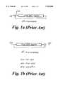
- FIG. 1a and 1billustrate respectively the construction of a transmitter scrambler and a corresponding receiver descrambler for use in a digital transmission system
- FIGS. 2a, 2b and 2cshow typical ATM payload sequences respectively prior to scrambling at the transmitter, after scrambling, and after descrambling at the receiver;
- FIGS. 1a and 1bThe implementation of a x 43 +1 scrambler and de-scrambler employed in a digital transmission system is shown in FIGS. 1a and 1b respectively.
- the operation of the scrambling and de-scrambling processis well known to those skilled in the art.
- the scrambler circuit(FIG. 1a) performs a summation of the current bit sample i(x) with a running sum of previous samples occurring at integer multiples of 43 bit offsets from the current sample to produce the scrambled output t(x).
- the de-scrambler(FIG. 1b) operates on the received signal r(x) to reverse the scrambling process by subtracting the current data sample from the previous data sample offset by 43 bit positions.
- e(x)represents an error introduced during transmission.
- FIG. 2aillustrates this.
- the payloads of the ATM cellsare fed in a continuous manner into the scrambler.
- the ATM cell headersare appended to the payloads and transmitted across the communications channel.
- the processis reversed as shown in FIG. 2b.
- the headersare removed and the payloads fed into the de-scrambler. In the absence of errors the output is identical to the input. However if bit errors are introduced by the channel then the de-scrambling process will multiply them, each single bit error resulting in 2 bit errors in the de-scrambled payload as shown in FIG. 2c.
- the duplicated errorsare offset from each other by 43 bits. Additionally, as the payloads are applied continuously to the scrambler a single bit error in one payload may spill over into the following payload due to this multiplication effect. Thus if the original bit in error occurs in payload bit positions 0 to 341 then the second bit error will occur in the same ATM payload which will then contain a double bit error. If however the original bit error occurs in payload bit position 342 to 383 then the secondary error will spill into the following payload and two consecutive ATM payloads will then each contain a single bit error.
- the preferred CRC-10 code described belowcomprises a 9th degree primitive polynomial code multiplied by (x+1). This code may be used to perform single bit correction and multiple bit detection over up to 511 bits. As the standard ATM payload is just 384 bits, the code is shortened. It will thus be appreciated that there will be unused syndromes even if the full payload is protected by the CRC. It is important to note that although the scrambling process is continuous the generation and decoding of the CRC is a blocked operation which occurs over a single (or part) of a payload only. The CRC operation is not dependent on previously occurring ATM samples. The generation of the CRC is performed prior to the scrambling process and the detection/correction performed after the de-scrambling process.
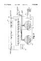
- the decoder/error correction arrangement of FIG. 3comprises four main blocks: a buffer register 131 that is used for temporary storage of the received code-word whilst the initial syndrome is computed; a CRC syndrome register 132 that computes the error syndrome from the received word; an x+1 parity register 133 that checks the parity of the received word; and an error correction stage that detects the bit positions of the bits in error and corrects them.
- the error correction stageincludes of two circuits. One circuit 134a is used to detect and correct single bit errors, the other circuit 134b detects and corrects double bit errors.
- a selection circuit 135selects on or other of the outputs of the error correction circuits 134a, 134b according to whether a single bit error or a double bit error has been corrected.
- the received wordis shifted simultaneously into the buffer register 131, the syndrome register 132 and the parity register 133.
- the syndrome registeris used to compute a syndrome error word, a non zero value indicating that an error has been detected in the received word.
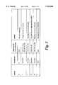
- the parityis zero (an odd number of errored bits is not detected by the parity check) and the syndrome is non-zero (an error detected by the syndrome decoder) then it is assumed that a double bit error has occurred, and further that the errored bits are offset by 43 bit positions due to the scrambler. Corrective action can be taken to correct the two bits in error and thus the double bit correction circuitry is selected.
- the syndromeis therefore shifted cyclically one bit at a time until a match is found. Simultaneously the received word is shifted from the buffer register. When a match is found, indicating the errored bit positions, the bits in error may be corrected and the syndrome reset. No further corrective action is required and the remaining bits of the received word are clocked out of the buffer register.
- Additional protection against mis-correction of multiple bit errorsmay be performed by further analysis of the computed syndrome, and a comparison of the errored bit position indicated by the process together with the knowledge of the error multiplication effects introduced by the system.
- the error code words used by the error correction circuitsare computed.
- the error code wordsare compared with the syndrome and when a match is found the bit position of the error is known. For a single bit error, the error code word is found simply by feeding a known code-word into the CRC syndrome decoder 132 with the MSB of the code word deliberately errored. The computed syndrome is used as the error code word. If the single bit error occurred in the next bit the resultant syndrome will be equal to the error code word cyclically shifted by one bit.
- the error code word used to detect double bit errorsis similarly computed. In this case the code word fed to the syndrome decoder 132 will be errored in both its MSB and the bit offset from the MSB by 43 bits.
- the resultant error code wordsare used by the error correction circuits 134a, 134b to trap the bit errors.
- the actual valuesare dependent on the length of the payload that is protected by the CRC. If the full payload is protected, the single bit correction code-word is ⁇ 0,0,1,1,1,1,0,0,0 ⁇ and the double bit error code word is ⁇ 0,1,1,1,1,0,1,1,1 ⁇ .
- These error code wordsare entered in the single bit error and double bit error detection circuits 144a and 144b respectively.
- the received code wordis clocked into the buffer register 131. It is simultaneously input into the syndrome (132) and parity (133) circuits and the syndrome and parity computed. The corrective action of the circuit is dependent on these computed values as discussed above with reference to FIG. 3.
- the corrective actionis performed by clocking the received code-word out of the buffer register 131.
- the output of the syndrome registeris compared with the error code word using an AND gate 136.
- the two valuesdo not match then the next bit is read from the buffer register and the syndrome shifted once cyclically. If after the shift, the syndrome matches the error-code word then the error position has been found and so-on.
- a simple shift register 137may be used to compute the bit position at which the error was detected (for double bit errors, the bit occurring in the most significant position is used). If a single bit error is being corrected it should lie either in the lower portion of the payload in bits 0 to 42 (indicating that the original error occurred in the previous payload and this error occurs due to the scrambler multiplication) or in the top portion of the payload in bits 341 to 383 (indicating that this is the original error and the second error will fall in the following payload).
- the two bitsmust fall in the ⁇ middle ⁇ of the payload and thus the most significant errored bit can range from positions 43 to 383). If in either case the expected bit positions are incorrect then a multiple bit error in the payload must be assumed and an alarm can be generated.
- the table shown in FIG. 5summarises the state table that can be used to determine the error condition of the code word.
Landscapes
- Engineering & Computer Science (AREA)
- Computer Networks & Wireless Communication (AREA)
- Signal Processing (AREA)
- Physics & Mathematics (AREA)
- Spectroscopy & Molecular Physics (AREA)
- Power Engineering (AREA)
- Error Detection And Correction (AREA)
Abstract
Description
r(x)=t(x)+e(x)
o(x)=t'(x)+e'(x)
i e'(x)=e(x)(x.sup.43 +1)
x.sup.10 +x.sup.9 +x.sup.4 +x+1
(x.sup.9 +x.sup.4 +1)·(x+1)
Claims (14)
Priority Applications (4)
| Application Number | Priority Date | Filing Date | Title |
|---|---|---|---|
| US08/869,352US5923680A (en) | 1997-06-05 | 1997-06-05 | Error correction in a digital transmission system |
| GB9804105AGB2326067A (en) | 1997-06-05 | 1998-02-27 | Error correction in a digital transmission system |
| EP98304125AEP0883260A3 (en) | 1997-06-05 | 1998-05-26 | Error correction in a digital transmission system |
| CA002235178ACA2235178A1 (en) | 1997-06-05 | 1998-06-04 | Error correction in a digital transmission system |
Applications Claiming Priority (1)
| Application Number | Priority Date | Filing Date | Title |
|---|---|---|---|
| US08/869,352US5923680A (en) | 1997-06-05 | 1997-06-05 | Error correction in a digital transmission system |
Publications (1)
| Publication Number | Publication Date |
|---|---|
| US5923680Atrue US5923680A (en) | 1999-07-13 |
Family
ID=25353396
Family Applications (1)
| Application Number | Title | Priority Date | Filing Date |
|---|---|---|---|
| US08/869,352Expired - LifetimeUS5923680A (en) | 1997-06-05 | 1997-06-05 | Error correction in a digital transmission system |
Country Status (4)
| Country | Link |
|---|---|
| US (1) | US5923680A (en) |
| EP (1) | EP0883260A3 (en) |
| CA (1) | CA2235178A1 (en) |
| GB (1) | GB2326067A (en) |
Cited By (16)
| Publication number | Priority date | Publication date | Assignee | Title |
|---|---|---|---|---|
| US6256355B1 (en)* | 1997-07-18 | 2001-07-03 | Sony Corporation | Transmitter, receiver, communication method and radio communication system |
| US6609226B1 (en)* | 2000-04-10 | 2003-08-19 | Nortel Networks Limited | Networking device and method for making cyclic redundancy check (CRC) immune to scrambler error duplication |
| US20040193997A1 (en)* | 2003-01-30 | 2004-09-30 | International Business Machines Corporation | Forward error correction scheme compatible with the bit error spreading of a scrambler |
| US20050119372A1 (en)* | 2001-05-02 | 2005-06-02 | L&L Products, Inc. | Two component (epoxy/amine) structural foam-in-place material |
| US20060282751A1 (en)* | 2005-05-24 | 2006-12-14 | Silicon Graphics, Inc. | Fault tolerant memory system |
| US20080109707A1 (en)* | 2006-11-03 | 2008-05-08 | Timothy Dell | Forward error correction encoding for multiple link transmission capatible with 64b/66b scrambling |
| CN100505069C (en)* | 2004-06-03 | 2009-06-24 | 联咏科技股份有限公司 | system and method for detecting errors in data |
| US20100153805A1 (en)* | 2006-03-09 | 2010-06-17 | Schmidt Brian K | Error detection in physical interfaces for point-to-point communications between integrated circuits |
| US7913151B1 (en)* | 2006-05-26 | 2011-03-22 | Pmc-Sierra, Inc. | Forward error correction with self-synchronous scramblers |
| US20110078545A1 (en)* | 2009-09-30 | 2011-03-31 | International Business Machines Corporation | Frame Boundary Detection and Synchronization System for Data Stream Received by Ethernet Forward Error Correction Layer |
| US20110099451A1 (en)* | 2009-10-22 | 2011-04-28 | Arm Limited | Error control coding for single error correction and double error detection |
| US20140344652A1 (en)* | 2011-12-02 | 2014-11-20 | Commisariat A L'energie Atomique Et Aux Energies Alternatives | Method for generating a maximized linear correcting code, method and device for decoding such a code |
| US20140372830A1 (en)* | 2013-06-13 | 2014-12-18 | Micron Technology, Inc. | Apparatuses and methods for error correction |
| US10727976B2 (en)* | 2017-10-03 | 2020-07-28 | Telefonaktiebolaget Lm Ericsson (Publ) | Bit order of NR PBCH payload to enhance polar code performance |
| US10970166B2 (en)* | 2019-02-19 | 2021-04-06 | Toshiba Memory Corporation | Memory system and method of controlling non-volatile memory |
| US11095307B2 (en)* | 2019-09-03 | 2021-08-17 | Nvidia Corporation | Performing cyclic redundancy checks using parallel computing architectures |
Families Citing this family (4)
| Publication number | Priority date | Publication date | Assignee | Title |
|---|---|---|---|---|
| US6826595B1 (en) | 2000-07-05 | 2004-11-30 | Sap Portals Israel, Ltd. | Internet collaboration system and method |
| US8139430B2 (en) | 2008-07-01 | 2012-03-20 | International Business Machines Corporation | Power-on initialization and test for a cascade interconnect memory system |
| US8201069B2 (en)* | 2008-07-01 | 2012-06-12 | International Business Machines Corporation | Cyclical redundancy code for use in a high-speed serial link |
| US8234540B2 (en) | 2008-07-01 | 2012-07-31 | International Business Machines Corporation | Error correcting code protected quasi-static bit communication on a high-speed bus |
Citations (8)
| Publication number | Priority date | Publication date | Assignee | Title |
|---|---|---|---|---|
| US3771126A (en)* | 1972-04-10 | 1973-11-06 | Bell Telephone Labor Inc | Error correction for self-synchronized scramblers |
| US3775746A (en)* | 1972-05-19 | 1973-11-27 | Ibm | Method and apparatus for detecting odd numbers of errors and burst errors of less than a predetermined length in scrambled digital sequences |
| US4435807A (en)* | 1980-06-26 | 1984-03-06 | Scott Edward W | Orchard error correction system |
| GB2131253A (en)* | 1982-11-24 | 1984-06-13 | Motorola Ltd | Error-correcting decoder |
| US4592054A (en)* | 1982-10-22 | 1986-05-27 | Mitsubishi Denki Kabushiki Kaisha | Decoder with code error correcting function |
| WO1992021086A1 (en)* | 1991-05-10 | 1992-11-26 | Echelon Corporation | Binary data error correction using hint signal |
| US5179560A (en)* | 1989-05-15 | 1993-01-12 | Mitsubishi Denki Kabushiki Kaisha | Apparatus for decoding bch code for correcting complex error |
| WO1995028046A1 (en)* | 1994-04-08 | 1995-10-19 | Echelon Corporation | Method and apparatus for robust communications based upon angular modulation |
- 1997
- 1997-06-05USUS08/869,352patent/US5923680A/ennot_activeExpired - Lifetime
- 1998
- 1998-02-27GBGB9804105Apatent/GB2326067A/ennot_activeWithdrawn
- 1998-05-26EPEP98304125Apatent/EP0883260A3/ennot_activeWithdrawn
- 1998-06-04CACA002235178Apatent/CA2235178A1/ennot_activeAbandoned
Patent Citations (8)
| Publication number | Priority date | Publication date | Assignee | Title |
|---|---|---|---|---|
| US3771126A (en)* | 1972-04-10 | 1973-11-06 | Bell Telephone Labor Inc | Error correction for self-synchronized scramblers |
| US3775746A (en)* | 1972-05-19 | 1973-11-27 | Ibm | Method and apparatus for detecting odd numbers of errors and burst errors of less than a predetermined length in scrambled digital sequences |
| US4435807A (en)* | 1980-06-26 | 1984-03-06 | Scott Edward W | Orchard error correction system |
| US4592054A (en)* | 1982-10-22 | 1986-05-27 | Mitsubishi Denki Kabushiki Kaisha | Decoder with code error correcting function |
| GB2131253A (en)* | 1982-11-24 | 1984-06-13 | Motorola Ltd | Error-correcting decoder |
| US5179560A (en)* | 1989-05-15 | 1993-01-12 | Mitsubishi Denki Kabushiki Kaisha | Apparatus for decoding bch code for correcting complex error |
| WO1992021086A1 (en)* | 1991-05-10 | 1992-11-26 | Echelon Corporation | Binary data error correction using hint signal |
| WO1995028046A1 (en)* | 1994-04-08 | 1995-10-19 | Echelon Corporation | Method and apparatus for robust communications based upon angular modulation |
Non-Patent Citations (2)
| Title |
|---|
| Dravida, "Error Control Aspects of High Speed Networks", INFOCOM '92, pp. 272-281, Dec. 1992. |
| Dravida, Error Control Aspects of High Speed Networks , INFOCOM 92, pp. 272 281, Dec. 1992.* |
Cited By (35)
| Publication number | Priority date | Publication date | Assignee | Title |
|---|---|---|---|---|
| US6256355B1 (en)* | 1997-07-18 | 2001-07-03 | Sony Corporation | Transmitter, receiver, communication method and radio communication system |
| US6609226B1 (en)* | 2000-04-10 | 2003-08-19 | Nortel Networks Limited | Networking device and method for making cyclic redundancy check (CRC) immune to scrambler error duplication |
| US20050119372A1 (en)* | 2001-05-02 | 2005-06-02 | L&L Products, Inc. | Two component (epoxy/amine) structural foam-in-place material |
| US20040193997A1 (en)* | 2003-01-30 | 2004-09-30 | International Business Machines Corporation | Forward error correction scheme compatible with the bit error spreading of a scrambler |
| US7284184B2 (en)* | 2003-01-30 | 2007-10-16 | International Business Machines Corporation | Forward error correction scheme compatible with the bit error spreading of a scrambler |
| US8055984B2 (en) | 2003-01-30 | 2011-11-08 | International Business Machines Corporation | Forward error correction scheme compatible with the bit error spreading of a scrambler |
| US20080172589A1 (en)* | 2003-01-30 | 2008-07-17 | Rene Gallezot | Forward error correction scheme compatible with the bit error spreading of a scrambler |
| CN100505069C (en)* | 2004-06-03 | 2009-06-24 | 联咏科技股份有限公司 | system and method for detecting errors in data |
| US7765454B2 (en)* | 2005-05-24 | 2010-07-27 | Sgi International, Inc. | Fault tolerant memory system |
| US20060282751A1 (en)* | 2005-05-24 | 2006-12-14 | Silicon Graphics, Inc. | Fault tolerant memory system |
| US20110209027A1 (en)* | 2006-03-09 | 2011-08-25 | Silicon Image, Inc. | Error detection in physical interfaces for point-to-point communications between integrated circuits |
| US7937644B2 (en)* | 2006-03-09 | 2011-05-03 | Silicon Image, Inc. | Error detection in physical interfaces for point-to-point communications between integrated circuits |
| US20100153805A1 (en)* | 2006-03-09 | 2010-06-17 | Schmidt Brian K | Error detection in physical interfaces for point-to-point communications between integrated circuits |
| US8099648B2 (en) | 2006-03-09 | 2012-01-17 | Silicon Image, Inc. | Error detection in physical interfaces for point-to-point communications between integrated circuits |
| US7913151B1 (en)* | 2006-05-26 | 2011-03-22 | Pmc-Sierra, Inc. | Forward error correction with self-synchronous scramblers |
| US8020077B1 (en) | 2006-05-26 | 2011-09-13 | Pmc-Sierra, Inc. | Forward error correction with self-synchronous scramblers |
| US7996747B2 (en) | 2006-11-03 | 2011-08-09 | International Business Machines Corporation | Forward error correction encoding for multiple link transmission compatible with 64B/66B scrambling |
| US20080109707A1 (en)* | 2006-11-03 | 2008-05-08 | Timothy Dell | Forward error correction encoding for multiple link transmission capatible with 64b/66b scrambling |
| KR101104033B1 (en) | 2006-11-03 | 2012-01-09 | 인터내셔널 비지네스 머신즈 코포레이션 | Forward error correction encoding for multiple link transmission compatible with 64b/66b scrambling |
| US20110078545A1 (en)* | 2009-09-30 | 2011-03-31 | International Business Machines Corporation | Frame Boundary Detection and Synchronization System for Data Stream Received by Ethernet Forward Error Correction Layer |
| US8667373B2 (en)* | 2009-09-30 | 2014-03-04 | International Business Machines Corporation | Frame boundary detection and synchronization system for data stream received by ethernet forward error correction layer |
| US20110099451A1 (en)* | 2009-10-22 | 2011-04-28 | Arm Limited | Error control coding for single error correction and double error detection |
| US8381083B2 (en)* | 2009-10-22 | 2013-02-19 | Arm Limited | Error control coding for single error correction and double error detection |
| US20140344652A1 (en)* | 2011-12-02 | 2014-11-20 | Commisariat A L'energie Atomique Et Aux Energies Alternatives | Method for generating a maximized linear correcting code, method and device for decoding such a code |
| US9520899B2 (en)* | 2011-12-02 | 2016-12-13 | Commisariat A L'energie Atomique Et Aux Energies Alternatives | Method for generating a maximized linear correcting code, method and device for decoding such a code |
| US20140372830A1 (en)* | 2013-06-13 | 2014-12-18 | Micron Technology, Inc. | Apparatuses and methods for error correction |
| US9218239B2 (en)* | 2013-06-13 | 2015-12-22 | Micron Technology, Inc. | Apparatuses and methods for error correction |
| US10727976B2 (en)* | 2017-10-03 | 2020-07-28 | Telefonaktiebolaget Lm Ericsson (Publ) | Bit order of NR PBCH payload to enhance polar code performance |
| US11394489B2 (en)* | 2017-10-03 | 2022-07-19 | Telefonaktiebolaget Lm Ericsson (Publ) | Bit order of NR PBCH payload to enhance polar code performance |
| US11855773B2 (en) | 2017-10-03 | 2023-12-26 | Telefonaktiebolaget Lm Ericsson (Publ) | Bit order of NR PBCH payload to enhance polar code performance |
| US12273191B2 (en) | 2017-10-03 | 2025-04-08 | Telefonaktiebolaget Lm Ericsson (Publ) | Bit order of NR PBCH payload to enhance polar code performance |
| US10970166B2 (en)* | 2019-02-19 | 2021-04-06 | Toshiba Memory Corporation | Memory system and method of controlling non-volatile memory |
| US11095307B2 (en)* | 2019-09-03 | 2021-08-17 | Nvidia Corporation | Performing cyclic redundancy checks using parallel computing architectures |
| US20220173752A1 (en)* | 2019-09-03 | 2022-06-02 | Nvidia Corporation | Performing cyclic redundancy checks using parallel computing architectures |
| US12003253B2 (en)* | 2019-09-03 | 2024-06-04 | Nvidia Corporation | Performing cyclic redundancy checks using parallel computing architectures |
Also Published As
| Publication number | Publication date |
|---|---|
| GB9804105D0 (en) | 1998-04-22 |
| CA2235178A1 (en) | 1998-12-05 |
| EP0883260A3 (en) | 2005-02-02 |
| EP0883260A2 (en) | 1998-12-09 |
| GB2326067A (en) | 1998-12-09 |
Similar Documents
| Publication | Publication Date | Title |
|---|---|---|
| US5923680A (en) | Error correction in a digital transmission system | |
| US8055984B2 (en) | Forward error correction scheme compatible with the bit error spreading of a scrambler | |
| US4979174A (en) | Error correction and detection apparatus and method | |
| KR100376822B1 (en) | Apparatus and method for synchronization and error detection of packetized data streams | |
| US7996747B2 (en) | Forward error correction encoding for multiple link transmission compatible with 64B/66B scrambling | |
| US6738942B1 (en) | Product code based forward error correction system | |
| US6044482A (en) | Digital transmission system for encoding and decoding attribute data into error checking symbols of main data | |
| US4119945A (en) | Error detection and correction | |
| JP3283097B2 (en) | Communications system | |
| US7353446B2 (en) | Cyclic redundancy check circuit for use with self-synchronous scramblers | |
| US8136013B2 (en) | Burst error correction based on fire code | |
| US7284182B2 (en) | Error correction on M-bit encoded links | |
| US8020077B1 (en) | Forward error correction with self-synchronous scramblers | |
| US20020104053A1 (en) | In-band FEC encoder for sonet | |
| US20020116679A1 (en) | In-band FEC decoder for sonet | |
| EP0571019B1 (en) | Extended error protected communication system | |
| Tong | Correction of synchronization errors with burst-error-correcting cyclic codes | |
| US3718905A (en) | Error correcting systems utilizing one-half optimum diffuse codes | |
| Juan | Erroneous MPEG packet synchronization in the MCNS/SCTE/ITU-T J. 83 Annex B standard | |
| JP2952051B2 (en) | Cell synchronous operation circuit in ATM | |
| Gorshe | Concurrent error detection | |
| US20020046370A1 (en) | Error checking | |
| EP1217751A2 (en) | Optimized parallel in parallel out GF(2M) multiplier for FEC decoder | |
| EP1204232A1 (en) | Detection of uncorrectable data blocks in coded communications systems | |
| EP1217749A2 (en) | In-band FEC error performance monitoring module for SONET |
Legal Events
| Date | Code | Title | Description |
|---|---|---|---|
| AS | Assignment | Owner name:NORTHERN TELECOM LIMITED, CANADA Free format text:ASSIGNMENT OF ASSIGNORS INTEREST;ASSIGNORS:BRUECKHEIMER, SIMON DANIEL;STACEY, DAVID JOHN;REEL/FRAME:009501/0078 Effective date:19970529 | |
| STCF | Information on status: patent grant | Free format text:PATENTED CASE | |
| AS | Assignment | Owner name:NORTEL NETWORKS CORPORATION, CANADA Free format text:CHANGE OF NAME;ASSIGNOR:NORTHERN TELECOM LIMITED;REEL/FRAME:010567/0001 Effective date:19990429 | |
| AS | Assignment | Owner name:NORTEL NETWORKS LIMITED, CANADA Free format text:CHANGE OF NAME;ASSIGNOR:NORTEL NETWORKS CORPORATION;REEL/FRAME:011195/0706 Effective date:20000830 Owner name:NORTEL NETWORKS LIMITED,CANADA Free format text:CHANGE OF NAME;ASSIGNOR:NORTEL NETWORKS CORPORATION;REEL/FRAME:011195/0706 Effective date:20000830 | |
| FPAY | Fee payment | Year of fee payment:4 | |
| FPAY | Fee payment | Year of fee payment:8 | |
| FPAY | Fee payment | Year of fee payment:12 | |
| AS | Assignment | Owner name:ERICSSON AB, SWEDEN Free format text:ASSIGNMENT OF PATENTS;ASSIGNOR:NORTEL NETWORKS LIMITED;REEL/FRAME:025979/0870 Effective date:20110311 |