US5923476A - Optical viewer with an aperture transformer - Google Patents
Optical viewer with an aperture transformerDownload PDFInfo
- Publication number
- US5923476A US5923476AUS09/007,917US791798AUS5923476AUS 5923476 AUS5923476 AUS 5923476AUS 791798 AUS791798 AUS 791798AUS 5923476 AUS5923476 AUS 5923476A
- Authority
- US
- United States
- Prior art keywords
- facets
- aperture
- light
- display screen
- optical system
- Prior art date
- Legal status (The legal status is an assumption and is not a legal conclusion. Google has not performed a legal analysis and makes no representation as to the accuracy of the status listed.)
- Expired - Fee Related
Links
- 230000003287optical effectEffects0.000titleclaimsabstractdescription25
- 210000001747pupilAnatomy0.000claimsabstractdescription11
- 210000005069earsAnatomy0.000description2
- 239000011521glassSubstances0.000description2
- 238000003384imaging methodMethods0.000description2
- 230000000712assemblyEffects0.000description1
- 238000000429assemblyMethods0.000description1
- 238000000034methodMethods0.000description1
- 238000012986modificationMethods0.000description1
- 230000004048modificationEffects0.000description1
- 239000012780transparent materialSubstances0.000description1
Images


Classifications
- G—PHYSICS
- G02—OPTICS
- G02B—OPTICAL ELEMENTS, SYSTEMS OR APPARATUS
- G02B27/00—Optical systems or apparatus not provided for by any of the groups G02B1/00 - G02B26/00, G02B30/00
- G02B27/01—Head-up displays
- G02B27/017—Head mounted
- G02B27/0172—Head mounted characterised by optical features
- G—PHYSICS
- G02—OPTICS
- G02B—OPTICAL ELEMENTS, SYSTEMS OR APPARATUS
- G02B27/00—Optical systems or apparatus not provided for by any of the groups G02B1/00 - G02B26/00, G02B30/00
- G02B27/01—Head-up displays
- G02B27/0101—Head-up displays characterised by optical features
- G02B2027/0132—Head-up displays characterised by optical features comprising binocular systems
- G—PHYSICS
- G02—OPTICS
- G02B—OPTICAL ELEMENTS, SYSTEMS OR APPARATUS
- G02B27/00—Optical systems or apparatus not provided for by any of the groups G02B1/00 - G02B26/00, G02B30/00
- G02B27/01—Head-up displays
- G02B27/017—Head mounted
- G02B2027/0178—Eyeglass type
Definitions
- the present inventionrelates to display systems, and more particularly, to head mounted display systems for projecting a computer generated image into the eyes of a person wearing the display system.
- Head-mounted computer displaysmay be viewed as "eye glasses" that are worn by the user to view images created by a computer.
- the image seen by each eyeis generated on a display screen having a two dimensional array of pixels. If the display screen is placed in front of the viewer's eyes, the resulting device extends outward from the viewer's face. This leads to a bulky display, which is objectionable both because of its size and weight.
- turning opticFor this type of design to be successful in reducing the weight and bulk of the portion of the display that extends out past the viewer's nose, some form of "turning optic" is needed in front of the user's eyes to reflect the image generated by the display screen back into the user's pupils.
- the simplest form of turning opticwould be a mirror that reflects the light generated by the display and imaging optics back into the eye.
- it can be shown that such an optical systemwould protrude forward from the face by approximately 3 cm or more. While this is an improvement over systems in which the display is placed in front of the viewer's face, it would be advantageous to reduce this thickness further.
- the present inventionis an optical system for reflecting light from a display screen into an aperture which is typically the pupil of a person wearing a head-mounted display system in which the display screen is mounted to the side of the viewer's eye.
- the optical systemincludes a turning optical assembly having a plurality of planar facets disposed on a surface opposite to the aperture. The planes of the facets are parallel to one another.
- the surfaceis curved. Light from the display entering an input port impinges on the facets such that the light is reflected by the facets into the aperture.
- the curved surfacehas a curvature chosen such that the fill factor for each of the facets is substantially the same as that for the others of the facets.
- the curved surfaceis a cylinder having a hyperbolic cross-section.
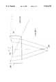
- FIG. 1is cross-sectional view of a head-mounted display on a user.
- FIG. 2is a cross-sectional view of turning optical assembly.
- FIG. 3is a cross-sectional view of a cross-sectional view of a turning optical assembly having a reduced thickness compared to the assembly shown in FIG. 2.
- FIG. 4is a cross-sectional view of a turning optical assembly according to the present invention.
- FIG. 1illustrates the manner in which a side-mounted display screens shown at 13 and 17 are viewed by a user 12 of a head mounted display 15 having displays 13 and 17 and turning optical assemblies 10 and 16 mounted on a frame 14.
- Light from the display screen 13is reflected into the wearer's eyes by turning optical assembly 10.
- One such optical assemblyis mounted in front of each eye.
- an optical assembly for reflecting light into an aperturewill be referred to as a "turning optic”.
- the simplest form of turning opticis shown in FIG. 2 at 25.
- the turning optic 25is a convex lens with a mirror 20 for reflecting the light generated by the display into the user's eye.
- the convex lens surfaceis shown at 21. It can be shown that for a typical field of view and for typical pupil and eye relief distances, the thickness of the turning optic must be approximately 3 cm. As noted above, it would be advantageous to reduce this thickness. It should be noted that the lens may be viewed as being part of the imaging optics associated with the display instead of part of the turning optic.
- the simplest method for reducing the thickness of the turning optic shown in FIG. 2is to collapse the mirror in a manner analogous to that used in collapsing a lens to generate a Fresnel lens.
- a portion of such a turning mirror 100is shown in FIG. 3 at 100.
- Mirror 100has a plurality of facets 102 inclined at the same angle, ⁇ , as mirror 20 shown in FIG. 2.
- Each mirror facet 102reflects the light generated by a small portion of the display into the viewer's pupil. This arrangement converts the narrow apertures defined by each of the facets into a sample from a corresponding wide aperture without losing any of the light generated by the display.
- the fill factorin the following discussion. It can be shown that when a uniformly illuminated display is viewed, the fill factor is proportional to the perceived light intensity in the wide aperture. In the arrangement shown in FIG. 3, the fill factor varies by over a factor of 7 across the field of view when realistic values are used for the size of the viewer's pupil and eye relief. While such a variation might be acceptable in some situations, in general, such variations in intensity are not desirable.
- the preferred embodiment of the present inventionavoids this variation in fill factor by varying the positions of the facets shown in FIG. 3 such that the fill factor is substantially constant across the field of view.
- the facetsmay be viewed as being mounted on a planar surface such that the distance from the facets to the user's eye is constant.
- the facetsare mounted on a curved surface.
- the angle of each facetremains the same, i.e., ⁇ .
- the surfaceis computed by requiring the fill factor to be constant across the field of view. It can be shown that the surface is approximated by the curve ##EQU1## where a is the distance from the center of the user's pupil to the nearest point on the curve.
- the coordinate system in which x and y are definedis shown in FIG. 4.
- FIG. 4is a cross-sectional view of a turning optic 200 according to the present invention.
- Turning optic 200is preferably constructed from a transparent material having an index of refraction greater than 1 so that lens 201 can be incorporated into the turning optic.
- the surface of turning optic 200 opposite to the user's pupil 204is curved and includes a plurality of facets 202 for reflecting light from the display into the user's pupil. Each of the facets is inclined at the same angle with respect to the y-axis. The curvature is chosen such that the fill factor is substantially constant across the turning optic.
- the turning optichas a cylindrical geometry, i.e., the facets are long planar surfaces similar to a set of venetian blinds disposed on a cylindrical surface having an approximately hyperbolic cross-section.
- the curved surfaceis not cylindrical will also be apparent to those skilled in the art from the preceding discussion.
- the surfacewould also be chosen to minimize variations in the fill factor in the direction perpendicular to the x and y directions shown in FIG. 4.
- the planes of all of the facetsmust still be parallel to one another to avoid "ghost" images.
Landscapes
- Physics & Mathematics (AREA)
- General Physics & Mathematics (AREA)
- Optics & Photonics (AREA)
Abstract
Description
Claims (7)
Priority Applications (1)
| Application Number | Priority Date | Filing Date | Title |
|---|---|---|---|
| US09/007,917US5923476A (en) | 1998-01-16 | 1998-01-16 | Optical viewer with an aperture transformer |
Applications Claiming Priority (1)
| Application Number | Priority Date | Filing Date | Title |
|---|---|---|---|
| US09/007,917US5923476A (en) | 1998-01-16 | 1998-01-16 | Optical viewer with an aperture transformer |
Publications (1)
| Publication Number | Publication Date |
|---|---|
| US5923476Atrue US5923476A (en) | 1999-07-13 |
Family
ID=21728799
Family Applications (1)
| Application Number | Title | Priority Date | Filing Date |
|---|---|---|---|
| US09/007,917Expired - Fee RelatedUS5923476A (en) | 1998-01-16 | 1998-01-16 | Optical viewer with an aperture transformer |
Country Status (1)
| Country | Link |
|---|---|
| US (1) | US5923476A (en) |
Cited By (9)
| Publication number | Priority date | Publication date | Assignee | Title |
|---|---|---|---|---|
| US9366869B2 (en) | 2014-11-10 | 2016-06-14 | Google Inc. | Thin curved eyepiece for see-through head wearable display |
| US9389422B1 (en) | 2013-12-23 | 2016-07-12 | Google Inc. | Eyepiece for head wearable display using partial and total internal reflections |
| US9395544B2 (en) | 2014-03-13 | 2016-07-19 | Google Inc. | Eyepiece with switchable reflector for head wearable display |
| US9442291B1 (en) | 2013-06-28 | 2016-09-13 | Google Inc. | Segmented diffractive optical elements for a head wearable display |
| US9459455B2 (en) | 2013-12-19 | 2016-10-04 | Google Inc. | See-through eyepiece for head wearable display |
| US9915823B1 (en) | 2014-05-06 | 2018-03-13 | Google Llc | Lightguide optical combiner for head wearable display |
| US10146054B2 (en) | 2015-07-06 | 2018-12-04 | Google Llc | Adding prescriptive correction to eyepieces for see-through head wearable displays |
| US10162180B2 (en) | 2015-06-04 | 2018-12-25 | Google Llc | Efficient thin curved eyepiece for see-through head wearable display |
| US11226261B2 (en)* | 2017-12-03 | 2022-01-18 | Lumus Ltd. | Optical device testing method and apparatus |
Citations (2)
| Publication number | Priority date | Publication date | Assignee | Title |
|---|---|---|---|---|
| US4220400A (en)* | 1977-02-22 | 1980-09-02 | Honeywell Inc. | Display apparatus with reflective separated structure |
| US4806011A (en)* | 1987-07-06 | 1989-02-21 | Bettinger David S | Spectacle-mounted ocular display apparatus |
- 1998
- 1998-01-16USUS09/007,917patent/US5923476A/ennot_activeExpired - Fee Related
Patent Citations (2)
| Publication number | Priority date | Publication date | Assignee | Title |
|---|---|---|---|---|
| US4220400A (en)* | 1977-02-22 | 1980-09-02 | Honeywell Inc. | Display apparatus with reflective separated structure |
| US4806011A (en)* | 1987-07-06 | 1989-02-21 | Bettinger David S | Spectacle-mounted ocular display apparatus |
Cited By (10)
| Publication number | Priority date | Publication date | Assignee | Title |
|---|---|---|---|---|
| US9442291B1 (en) | 2013-06-28 | 2016-09-13 | Google Inc. | Segmented diffractive optical elements for a head wearable display |
| US9459455B2 (en) | 2013-12-19 | 2016-10-04 | Google Inc. | See-through eyepiece for head wearable display |
| US9671614B2 (en) | 2013-12-19 | 2017-06-06 | Google Inc. | See-through eyepiece for head wearable display |
| US9389422B1 (en) | 2013-12-23 | 2016-07-12 | Google Inc. | Eyepiece for head wearable display using partial and total internal reflections |
| US9395544B2 (en) | 2014-03-13 | 2016-07-19 | Google Inc. | Eyepiece with switchable reflector for head wearable display |
| US9915823B1 (en) | 2014-05-06 | 2018-03-13 | Google Llc | Lightguide optical combiner for head wearable display |
| US9366869B2 (en) | 2014-11-10 | 2016-06-14 | Google Inc. | Thin curved eyepiece for see-through head wearable display |
| US10162180B2 (en) | 2015-06-04 | 2018-12-25 | Google Llc | Efficient thin curved eyepiece for see-through head wearable display |
| US10146054B2 (en) | 2015-07-06 | 2018-12-04 | Google Llc | Adding prescriptive correction to eyepieces for see-through head wearable displays |
| US11226261B2 (en)* | 2017-12-03 | 2022-01-18 | Lumus Ltd. | Optical device testing method and apparatus |
Similar Documents
| Publication | Publication Date | Title |
|---|---|---|
| US6185045B1 (en) | Image display apparatus with mechanism for modifying the appearance of the periphery of a display device | |
| US6124977A (en) | Image display apparatus | |
| US6417970B1 (en) | Two stage optical system for head mounted display | |
| JP2896606B2 (en) | Image display device | |
| US6204975B1 (en) | Reflective micro-display system | |
| CA1318528C (en) | Compact see-through night vision goggles | |
| US5812100A (en) | Image display apparatus | |
| KR100412760B1 (en) | Head mounted display devices and optical systems for displays used in these devices | |
| JP7392433B2 (en) | head mounted display device | |
| WO1996005533A1 (en) | Method and apparatus for direct retinal projection | |
| KR102255781B1 (en) | Compatct type optical device for augmented reality | |
| JP3496890B2 (en) | Display device | |
| US5923476A (en) | Optical viewer with an aperture transformer | |
| US11741863B2 (en) | Eyeglass-integrated display device using multiple embedded projectors and display windows | |
| JP2003043409A (en) | Image display device | |
| US6252565B1 (en) | Elliptical cavity optical retinal display | |
| KR102282422B1 (en) | Compact type optical device for augmented reality which can prevent ghost images with wide field of view | |
| JP7342659B2 (en) | Head-mounted display device and display method | |
| JPH0965245A (en) | Image display device | |
| US20240045202A1 (en) | Pupil Tracking Near-Eye Display | |
| KR102302159B1 (en) | Optical device for augmented reality preventing light leakage | |
| US4422720A (en) | Stereoscopic viewing and projection system | |
| EP1326118A2 (en) | Wide angle display device using compact prism eyepieces | |
| KR102334813B1 (en) | Optical device for augmented reality which can prevent ghost images | |
| KR102345319B1 (en) | Optical device for augmented reality which can prevent ghost images |
Legal Events
| Date | Code | Title | Description |
|---|---|---|---|
| AS | Assignment | Owner name:HEWLETT-PACKARD COMPANY, CALIFORNIA Free format text:ASSIGNMENT OF ASSIGNORS INTEREST;ASSIGNOR:HEFFNER, BRIAN;REEL/FRAME:009061/0332 Effective date:19980116 | |
| AS | Assignment | Owner name:HEWLETT-PACKARD COMPANY, A DELAWARE CORPORATION, C Free format text:MERGER;ASSIGNOR:HEWLETT-PACKARD COMPANY, A CALIFORNIA CORPORATION;REEL/FRAME:010841/0649 Effective date:19980520 | |
| AS | Assignment | Owner name:AGILENT TECHNOLOGIES INC, CALIFORNIA Free format text:ASSIGNMENT OF ASSIGNORS INTEREST;ASSIGNOR:HEWLETT-PACKARD COMPANY;REEL/FRAME:010977/0540 Effective date:19991101 | |
| FEPP | Fee payment procedure | Free format text:PAYOR NUMBER ASSIGNED (ORIGINAL EVENT CODE: ASPN); ENTITY STATUS OF PATENT OWNER: LARGE ENTITY | |
| REMI | Maintenance fee reminder mailed | ||
| LAPS | Lapse for failure to pay maintenance fees | ||
| FP | Lapsed due to failure to pay maintenance fee | Effective date:20030713 | |
| AS | Assignment | Owner name:AVAGO TECHNOLOGIES GENERAL IP (SINGAPORE) PTE. LTD Free format text:ASSIGNMENT OF ASSIGNORS INTEREST;ASSIGNOR:AGILENT TECHNOLOGIES, INC.;REEL/FRAME:018367/0245 Effective date:20051201 | |
| STCH | Information on status: patent discontinuation | Free format text:PATENT EXPIRED DUE TO NONPAYMENT OF MAINTENANCE FEES UNDER 37 CFR 1.362 |