US5923475A - Laser printer using a fly's eye integrator - Google Patents
Laser printer using a fly's eye integratorDownload PDFInfo
- Publication number
- US5923475A US5923475AUS08/757,889US75788996AUS5923475AUS 5923475 AUS5923475 AUS 5923475AUS 75788996 AUS75788996 AUS 75788996AUS 5923475 AUS5923475 AUS 5923475A
- Authority
- US
- United States
- Prior art keywords
- laser
- array
- lenslet
- light
- laser diode
- Prior art date
- Legal status (The legal status is an assumption and is not a legal conclusion. Google has not performed a legal analysis and makes no representation as to the accuracy of the status listed.)
- Expired - Lifetime
Links
Images


Classifications
- G—PHYSICS
- G02—OPTICS
- G02B—OPTICAL ELEMENTS, SYSTEMS OR APPARATUS
- G02B19/00—Condensers, e.g. light collectors or similar non-imaging optics
- G02B19/0033—Condensers, e.g. light collectors or similar non-imaging optics characterised by the use
- G02B19/0047—Condensers, e.g. light collectors or similar non-imaging optics characterised by the use for use with a light source
- G02B19/0052—Condensers, e.g. light collectors or similar non-imaging optics characterised by the use for use with a light source the light source comprising a laser diode
- G02B19/0057—Condensers, e.g. light collectors or similar non-imaging optics characterised by the use for use with a light source the light source comprising a laser diode in the form of a laser diode array, e.g. laser diode bar
- B—PERFORMING OPERATIONS; TRANSPORTING
- B41—PRINTING; LINING MACHINES; TYPEWRITERS; STAMPS
- B41J—TYPEWRITERS; SELECTIVE PRINTING MECHANISMS, i.e. MECHANISMS PRINTING OTHERWISE THAN FROM A FORME; CORRECTION OF TYPOGRAPHICAL ERRORS
- B41J2/00—Typewriters or selective printing mechanisms characterised by the printing or marking process for which they are designed
- B41J2/435—Typewriters or selective printing mechanisms characterised by the printing or marking process for which they are designed characterised by selective application of radiation to a printing material or impression-transfer material
- B41J2/447—Typewriters or selective printing mechanisms characterised by the printing or marking process for which they are designed characterised by selective application of radiation to a printing material or impression-transfer material using arrays of radiation sources
- B41J2/45—Typewriters or selective printing mechanisms characterised by the printing or marking process for which they are designed characterised by selective application of radiation to a printing material or impression-transfer material using arrays of radiation sources using light-emitting diode [LED] or laser arrays
- B41J2/451—Special optical means therefor, e.g. lenses, mirrors, focusing means
- B—PERFORMING OPERATIONS; TRANSPORTING
- B41—PRINTING; LINING MACHINES; TYPEWRITERS; STAMPS
- B41J—TYPEWRITERS; SELECTIVE PRINTING MECHANISMS, i.e. MECHANISMS PRINTING OTHERWISE THAN FROM A FORME; CORRECTION OF TYPOGRAPHICAL ERRORS
- B41J2/00—Typewriters or selective printing mechanisms characterised by the printing or marking process for which they are designed
- B41J2/435—Typewriters or selective printing mechanisms characterised by the printing or marking process for which they are designed characterised by selective application of radiation to a printing material or impression-transfer material
- B41J2/465—Typewriters or selective printing mechanisms characterised by the printing or marking process for which they are designed characterised by selective application of radiation to a printing material or impression-transfer material using masks, e.g. light-switching masks
- G—PHYSICS
- G02—OPTICS
- G02B—OPTICAL ELEMENTS, SYSTEMS OR APPARATUS
- G02B19/00—Condensers, e.g. light collectors or similar non-imaging optics
- G02B19/0004—Condensers, e.g. light collectors or similar non-imaging optics characterised by the optical means employed
- G02B19/0009—Condensers, e.g. light collectors or similar non-imaging optics characterised by the optical means employed having refractive surfaces only
- G02B19/0014—Condensers, e.g. light collectors or similar non-imaging optics characterised by the optical means employed having refractive surfaces only at least one surface having optical power
- G—PHYSICS
- G02—OPTICS
- G02B—OPTICAL ELEMENTS, SYSTEMS OR APPARATUS
- G02B27/00—Optical systems or apparatus not provided for by any of the groups G02B1/00 - G02B26/00, G02B30/00
- G02B27/09—Beam shaping, e.g. changing the cross-sectional area, not otherwise provided for
- G—PHYSICS
- G02—OPTICS
- G02B—OPTICAL ELEMENTS, SYSTEMS OR APPARATUS
- G02B27/00—Optical systems or apparatus not provided for by any of the groups G02B1/00 - G02B26/00, G02B30/00
- G02B27/09—Beam shaping, e.g. changing the cross-sectional area, not otherwise provided for
- G02B27/0938—Using specific optical elements
- G02B27/095—Refractive optical elements
- G02B27/0955—Lenses
- G02B27/0961—Lens arrays
- G—PHYSICS
- G02—OPTICS
- G02B—OPTICAL ELEMENTS, SYSTEMS OR APPARATUS
- G02B27/00—Optical systems or apparatus not provided for by any of the groups G02B1/00 - G02B26/00, G02B30/00
- G02B27/09—Beam shaping, e.g. changing the cross-sectional area, not otherwise provided for
- G02B27/0938—Using specific optical elements
- G02B27/095—Refractive optical elements
- G02B27/0955—Lenses
- G02B27/0966—Cylindrical lenses
Definitions
- the present inventionrelates to laser printers in general, and in particular, to a laser printer with a laser diode array source, a spatial light modulator, a laser lenslet array, and a fly's eye integrator assembly.
- a typical laser printerradiation from a laser is shaped, and imaged onto a film plane to produce a desired spot size.
- the spotcalled a pixel, forms the smallest element of the image.
- the laser radiationis modulated to create the correct density of each spot, pixel by pixel.
- the laser spotis scanned in the line direction, and the media is moved in the page direction to create a two dimensional image.
- an external modulatorsuch as an acousto-optical device, is used to input the image data into the optical beam.
- the laser radiationis typically modulated directly by varying the current input to the laser.
- high throughputis obtained by scanning the laser beam in the line direction with a polygonal mirror or a galvanometer. These printers are called “flying spot" printers.
- a low sensitivity media printersuch as a laser thermal printer
- higher power laser sources and slow line and page scan speedsare used to meet the high exposure requirements, which are typically 0.2-0.5 joules/cm 2 .
- One way to achieve this type of scanis to configure the printer like a "lathe", where the page scan is obtained by rotating a drum which holds the film, and line scan, by translating the laser in a direction parallel to the axis of rotation of the drum.
- Another approachis to utilize a monolithic array of laser sources, and then image the elements of the laser array directly onto the light sensitive media to produce multiple spots. Power to each element of the laser array is individually modulated to obtain pixel densities.
- Such a systemdescribed by U.S. Pat. No. 4,804,975, is potentially of lower cost and higher efficiency compared to systems which couple the lasers to optical fibers.
- monolithic laser diode arrayshave their own disadvantages. When the individual lasing elements are imaged directly to the media, failure of even one element in the array introduces a pattern error. Also, the electronics to modulate high current inputs to the diodes at high speeds are expensive and difficult to manufacture. Furthermore, the system is also sensitive to image artifacts caused by thermal and electrical crosstalk effects within the diode laser array package.
- Another approach to improving a system with a monolithic diode array sourcesis to combine the light from each lasing element to flood illuminate a spatial light modulator.
- the elements of the modulatorbreak up the light into image elements, and each element of the modulator is subsequently imaged onto the media plane to form the desired array of printing spots.
- Systems employing this approachare described in U.S. Pat. Nos. 5,517,359 and 5,521,748. These systems improve upon the prior art designs by providing indirect light modulation means, so that the laser diode array source operates at full power, and serves only as a light source.
- the systems described in these patentshave a disadvantage in that the illumination provided to the modulator plane may be substantially non-uniform.
- the emitting elementsare imaged directly onto the modulator at a high magnification.
- the resulting modulator illuminationmay be significantly non-uniform.
- U.S. Pat. No. 5,517,359includes a mirror system which partially compensates for these problems by substantially removing the macro-nonuniformities, but at the cost of some reduced brightness due to the increased angular spread of illumination to the modulator. Also, this uniformization method only works well when the light profile across the emitting elements already has large areas which are substantially uniform.
- 4,939,630describes a similar photolithographic illumination system, which utilizes a laser, such as an excimer or YAG laser, as the source.
- a lasersuch as an excimer or YAG laser
- These light sources, the arc lamp, excimer laser, and YAG laser,are large, spatially continuous sources, which emit beams of substantial size.
- a laser diode arrayis a segmented source, which consists of a series of small, distinct emitting sources, substantially separated from each other spatially.
- Another object of this inventionis to provide an illumination system for a laser printer utilizing a laser diode array, which has fewer components and a reduced size compared to prior art systems.
- Still another objectis to provide an illumination system for a laser printer utilizing a laser diode array, wherein the angular spectrum of the light incident to the spatial light modulator can be tailored to enhance the quality of modulation.
- a laser printeris comprised of a laser diode array, which provides an illumination source, a laser lenslet array, a fly's eye integrator system and other optical elements to illuminate a modulator array in the form of a spatial light modulator in a fashion that is substantially homogenized both angularly and spatially.
- the spatial light modulatora reflective or transmissive device, is illuminated uniformly by all elements of the laser.
- the elements of the spatila light modulatorbreak up the light into image elements, which are imaged to a media plane, to form a pattern of spots.
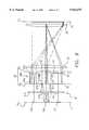
- FIG. 1is a perspective view of a laser printer according to the present invention.
- FIG. 2is a top plan view of a portion of the invention shown in FIG. 1, showing additional details of the optics arrangement, and particularly the optics layout prior to the modulator.
- FIG. 3is a top plan view of an alterative embodiment of the invention, showing details of the laser lenslet array and the uniformizer lenslet arrays.
- FIG. 4is a top plan view of another embodiment of the invention with gaps in the angular spectrum.
- FIG. 5is a plot illustrating the near field spatial light profile typical to a multimode laser diode array emitter.
- FIG. 6is a top plan view of an additional embodiment of a laser printer according to the present invention.
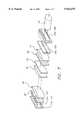
- FIG. 7is a perspective view of yet another embodiment of a laser printer according to the present invention.
- a preferred embodiment of the present invention for a laser printeris shown in the context of a laser printer, referred to in general by numeral 10 in FIG. 1.
- the laser printeris comprised of a laser diode array 11, illumination optics 20, a spatial light modulator 40, print lens 50, and a receiver, located at a media plane 60.
- Laser diode array 11is a high power array of laser diode emitters 12.
- the emitters 12 of the arrayare each activated simultaneously using a common power supply (not shown) in a CW (Continuous Wave) manner.
- CWContinuous Wave
- the light from each lasing elementis mapped by illumination optics 20 to cover the full width of the spatial light modulator 40, thereby providing source redundancy, and reducing the sensitivity of the system to the malfunction of any one laser diode emitter 12.
- the illumination optics 20are shown as anamorphic, meaning there are separate optical systems designed for the array and cross array directions, as the light output by the laser diode emitters has vastly different characteristics in the two directions. It should be understood that some axially symmetrical components, with power in both directions, could also be used.
- the cross array elementsconsist of the fiber lens 21 and cross array lens 22, as well as components (not shown) for correcting cross array smile error. In general, these cross array elements are designed to confine the light within the vertical width of the modulator, while minimizing the cross array numerical aperture (NA). This can be accomplished by imaging the laser diode emitters 12 to the spatial light modulator 40. Alternatively, the fiber lens 21, or its back focal plane, can be imaged to the modulator. These latter configurations assist in desensitizing the system to smile error.
- NAcross array numerical aperture
- the illumination optics 20also includes many other elements, such as a laser lenslet array 24, a combiner field lens 25, a fly's eye integrator 23, and a field lens 28, all of which are shown as cylindrical elements.
- the fly's eye integrator 23consists of first uniformizer lenslet array 29, second uniformizer lenslet array 30, and field lenses 26 and 27.
- the array direction opticsare designed to provide uniform illumination of the modulator by dividing the light from each laser diode emitter 12 into multiple portions, and then overlapping all of these portions over the full length of the spatial light modulator 40.
- the array and cross array opticsflood illuminate the modulator with a long, narrow, line of light of uniform radiance, while largely preserving the brightness of the laser diode array source (less transmission and other losses), and providing redundancy relative to the emitters.
- the line of illuminationextends the full length of the modulator in the array direction, while illuminating a narrow width in the cross array direction, roughly equivalent to the width of the sites of the spatial light modulator 40.
- the illuminated modulatoris imaged to the media plane 60 by a print lens 50 to create a line of closely packed writing spots.
- the print lens 50is typically a multi-element assembly, which may either be axially symmetric or anamorphic.
- additional optical elementsmay be included in the print lens elements as part of the modulation process.
- a polarization analyzersuch as a beamsplitting cube, would be located downstream of the modulator.
- the optical system beyond the modulatorwould be a schlieren system. In that case, a stop structure could be located within the print lens assembly to phase discriminate the modulated and unmodulated light at a fourier plane.
- the system of FIG. 1utilizes a fly's eye integrator 23 to improve the illumination uniformity, very much as is classically done in photolithography systems, except that the fly's eye integrator is further adapted to work with a segmented source, such as laser diode array 11.
- Konno, U.S. Pat. No. 4,497,015illustrates an illumination design for photolithography, which incorporates fly's eye integrator.
- a first fly's eye stagewhich includes two lenslet arrays a focal length apart, is used to break the beam up from the arc lamp source into many smaller beams.
- the second lenslet of the pairin combination with a field lens, images the beams from the corresponding first lenslets in overlapping fashion to an intermediate image plane.
- a system described in Kikuchi, U.S. Pat. No. 4,939,630is similar to that of Konno, except that it is adapted to work with the large, nearly collimated beam from an excimer laser.
- the first stage uniformizeris simplified to have a single lenslet array, which breaks the large beam into subportions which are then overlapped.
- a second stage uniformizer, with a pair of lenslet arrays and field lenses,then follows, in similar fashion to Konno.
- the FIG. 1 systemis similar in concept to those of Konno and Kikuchi, except that the source, laser diode array 11, is already segmented into many emitter areas. The light from these emitters can be combined in overlapping fashion without having to subsanmple the emitters into many smaller beams.
- laser lenslet array 24 and combiner field lens 25create an intermediate illumination plane, which is then input into the fly's eye integrator 23.
- the light profileis typically more uniform, but the integration is incomplete. All points within the illuminated area may not see light from all points of the source, or all points within the area may not see the full angular range of incident light.
- the fly's eye integrator 23is used to further improve the uniformity.
- the light incident to the first uniformizer lenslet array 29comprises a secondary source at the intermediate illumination plane, which will be imaged by the fly's eye integrator 23.
- the fly's eye integrator 23includes a first plurality of lenslets (those of first uniformizer lenslet array 29), arranged parallel to the optical axis 13, for subsampling the intermediate illumination plane input to the fly's eye integrator 23. These lenslets (of first uniformizer lenslet array 29) form a plurality of images of laser lenslet array 24 onto a first focal plane.
- the fly's eye integrator 23then includes a second plurality of lenslets (second uniformizer lenslet array 30) located in the vicinity of this first focal plane, and corresponding respectively to the first plurality of lenslets, which in turn, working with field lens 27, form images of the first plurality of lenslets (first uniformizer lens let array 29) at a second focal plane.
- the fly's eye integratorincludes a field lens 27 which causes this plurality of images at the second focal plane to be overlapped onto each other in a centered fashion.
- the fly's eye integrator 23may also include an input field lens 26 to alter the input light to be telecentric into the assembly.
- the laser diode array 11 at plane a 0is spatially segmented into N 1 sources, which are typically large area multimode laser diode emitters.
- these laser diode emitters 12are not closely packed, so as to minimize thermal crosstalk effects.
- the light from each laser diode emitter 12is not temporally or spatially coherent with light from any other laser diode emitter, so the light can be superimposed without inducing interference effects that would degrade illumination uniformity.
- the lightis generally incoherent across the laser diode emitters themselves, except in very localized areas, so the light from a given laser diode emitter can be broken up and overlapped, again without significant interference effects.
- these laser diode emitterscan be regarded as miniature extended sources, as opposed to being the point light sources that many lasers approximate.
- each of these laser diode emittersWhen each of these laser diode emitters is imaged in overlapping fashion to the intermediate illumination plane a 1 of FIG. 2, the incident light at a 1 is only partially mixed.
- the light from the various laser diode emittershas been overlapped, but the laser diode emitters have not been subsampled and mixed angularly or spatially.
- light from the n-axis points of each laser diode emitterwill collect at the center of the a 1 plane, and light from the off-axis points of each laser diode emitter will collect at the off-axis points of the a 1 illuminated area.
- the raypaths drawn from the various laser diode emitters 12a, 12b and 12cillustrate this.
- fly's eye integrator 23which consists of field lenses 26 and 27, and the uniformizer lenslet arrays 29, 30, is incorporated in the optics system to subsample the laser diode emitters, and more completely mix the light from them both angularly and spatially.
- planes a 0 , a 1 , and a 2are conjugate to each other.
- Planes b 0 and b 1are also conjugate to each other.
- the laser lenslet array 24consists of N 1 lens elements, with each lens element corresponding to a given laser diode emitter 12 of the laser diode array 11.
- Each lenslet element 24 a , 24 b and 24 cworks in combination with the combiner field lens 25 to image a laser diode emitter at high magnification onto the input face of the first uniformizer lenslet array 29 at plane a 1 .
- an on-axis caseis illustrated by the raypaths drawn from laser diode emitter 12b, through lenslet element 24b and lens 25 to the first uniformizer lenslet array 29.
- Two off-axis imaging casesare illustrated by raypaths from laser diode emitter 12a through lenslet element 24a and lens 25, as well as from laser diode emitter 12c through lenslet element 24c and lens 25.
- Field lens 26alters the incoming light to be telecentric to the first uniformizer lenslet array 29 at plane a 1 .
- the light at the intermediate illumination plane a 1is broken into N 2 portions, where N 2 is the number of lenslet elements in each of the uniformizer lenslet arrays 29,30.
- the corresponding lenslet elements in the second uniformizer lenslet array 30work together with the field lens 27 to image the lenslet elements of the first uniformizer lenslet array 29 in a magnified and overlapping fashion onto the a 2 plane (also referred to as the modulator plane 41).
- the field lens 28operates in a similar fashion as lens 26, to make the input light telecentic to the a 2 illumination plane.
- localized non-uniformity's in the light distribution at the a 1 planeare magnified spatially and spread across much of the a 2 illumination plane.
- a typical laser diode arraysuch as the Optopower OPC-D020 laser (Opto Power Corporation, Arlington, Az.), is a 20 Watt laser consisting of 19 diode laser elements, each 150 ⁇ m wide, and spaced apart on a 650 ⁇ m pitch, for an overall array length of 11.85 mm.
- This laser arrayemits linearly polarized light at 830 nm, with an array NA of 0.13.
- the focal length of the lenslet elementsis then 2.47 mm.
- Each of the uniformizer lenslet arrays 29 and 30consists of 6 lenslet elements, with 1 mm array direction lenslet widths.
- the combiner field lens 25then has a focal length of 99 m, so that the 6 mm width of array 29 is filled with light. Then, the lenslet elements of the uniformizer lenslet arrays 29, 30 have 8.0 mm focal lengths, which ensures that the output faces of the lenslets at the b 1 plane are filled with light as well.
- the focal length of field lens 27is 123 mm, so that the appropriate magnification is provided to illuminate the fill length of the modulator.
- Field lens 28then has the same 123 ⁇ m focal length.
- the illumination system from laser to modulatorhas an overall length of about 240 mm.
- the laser lenslet array and uniformizer lenslet arraysare depicted as cylindrical refractive components, but they might be diffractive, or have a spherical or aspherical lensing profiles.
- the uniformizer lenslet arrayscan be constructed as two separate elements, as shown in FIGS. 1 and 2, or as a solid optical element, with power surfaces on both sides of one piece, as shown in FIG. 3.
- the laser lenslet array 24 shown in FIG. 2is designed to work at infinite conjugates, so as to collimate the light from the laser diode emitters.
- the field lens 25completes the imaging and overlapping.
- the lenslets of laser lenslet array 24can be made to the same pitch as the laser diode array 11, but the optical axes of the lenslets of laser lenslet array 24 are shifted.
- the lenslets of laser lenslet array 24retain their full apertures, so that the maximal light is collected, while the effective power of the lenslets is altered.
- the lenslet shapeswould be constructed as off axis arcuate sections. This alternate method also allows the field lens 25 to be eliminated, as its function is incorporated into the laser lenslet array 24.
- the uniformizer lenslet arrays 29 and 30can also be constructed with multifunctionality.
- the lenslets of first uniformizer lenslet array 29can be designed to include the functions of field lens 26, so that lens 26 can be eliminated.
- the telecentricity function of the field lenscan be provided by constructing the lenslets of first uniformizer lenslet array 29 as off-axis arcuate sections.
- the imaging function of the field lenscan be provided by designing the lenslet elements to work at finite conjugates. Then the distance between the uniformizer lenslet arrays 29 and 30 is no longer one focal length, but the appropriate (and larger) distance required for proper imaging.
- the second uniformizer lenslet array 30could be designed to incorporate the imaging and telecentricity properties of the field lens 27.
- the illumination systemis also adaptable to the special requirements of spatial light modulator technology.
- secondary illumination altering meanscan be placed in the vicinity of the uniformly illuminated modulator plane 41 shown in FIG. 2.
- the fill factorratio of the site aperture/site pitch
- the fly's eye integrator 23is designed so that the lag range per pair of uniformizer lenslet array 29,30 is reduced, which causes the lenslet elements of uniformizer lenslet array 30 to be underfalled (light is only in the central portions of the elements). This can be accomplished by increasing the number of lenslet pairs.
- the incoming light to the modulator plane 41then has gaps ⁇ in the angle space, which, when the light is unmodulated, travel through the spatial light modulator, and hit the picket fence stop structure 53.
- This stop structure 53is located at a focus created by lens elements within the print lens 50, such as lens elements, 51' which act as a fourier transform lens.
- both the light and the gapsare phase shifted, causing an angular displacement at the stop 53, allowing light to be put through the transmitting areas of the stop, and onwards, and to be imaged at the media plane 60.
- FIG. 4shows a portion of the illumination to an on-axis modulator site of spatial light modulator 40 being illuminated, including the angular gaps ⁇ , and then an exemplary angular swath of light, ⁇ 2 , being transmitted through the stop.
- the stop structure 53can be designed to block (as shown) or transmit, the unmodulated light, depending on the location of the opaque blocking elements.
- the pre-modulator illumination systemis based on a classical Koehler illumination design approach.
- This systemalso utilizes a segmented fly's eye integrator 35 together with the segmented light source, laser diode array 11.
- the source (laser diode emitters 12) at plane a 0is imaged indirectly, via conjugate plane a 1 , to the object (the spatial light modulator, located at conjugate plane a 2 ), which is in turn imaged to the media plane 60.
- the system of FIG. 2is principally an altered version of a classical critical illumination system. By comparison, in the system of FIG.
- the source(laser diode emitters 12) are imaged to an intermediate plane a 1 , which is in turn imaged to the entrance pupil of the print lens 50 (not shown).
- the optical system of FIG. 3uses the laser lenslet array 31 to generate image space telecentric Koehler style illumination at the b 0 plane, where, in localized areas of the b 0 plane, each point is overlap illuminated by each source point of a given laser diode emitter 12.
- the light profile within these localized areasis inherently more uniform than the light profiles of the emitters themselves.
- These localized areas of the b 0 planeare subsampled and re-imaged by means of the segmented fly's eye integrator 35 which consists of elements 32, 33, and 34, in overlapping fashion to the conjugate plane b 1 , which is also the modulator plane 41, thus flood illuminating the spatial light modulator 40.
- the spatial light modulatoris then imaged at the appropriate magnification by the print lens 50 to the media plane 60, to create a line of closely packed writing spots (not shown).
- the system of FIG. 3adapts the segmented nature of the laser diode array source advantageously, by segmenting the fly's eye integrator 35 into N 1 uniformizer subways 36 corresponding to the N 1 laser diode emitters 12 of laser diode array 11.
- uniformizer lenslet array elements 32a and 33acorrespond to a given laser diode emitter 12a and laser lenslet array element 31a.
- Each laser lenslet array element 31provides Koehler style illumination from the corresponding emitter, to a portion of the b 0 plane.
- each uniformizer lenslet array element 32is magnified and overlap imaged to the b 1 plane by the corresponding uniformizer lenslet array element 33 and combiner field lens 34.
- the center of each lenslet element 32is imaged to the center of the modulator plane b 1 (also plane 41), as shown by the raypaths R, R', and R".
- the edge of each uniformizer lenslet array element 32goes to the edge of the illuminated area in the b 1 plane, as shown by raypaths S and S'.
- the spatial uniformity of the light at the spatial light modulator, in plane b 1should be considerably improved, as it assembled from the averaging of the N 3 subsamples of the Koehler illuminated b 0 plane, for all the N 1 laser diode emitters.
- the angular averaging of this embodimentcan be somewhat compromised however.
- light that collects near the optical axis at the b 1 illumination planewill include some low angle light from the laser diode emitters, and predominately high angle originating light, but almost no mid-angle originating light.
- light that collects near the edges of the illuminated area in the b 1 planewill be composed predominately of light that exited the laser diode emitters at mid-angles, with some high angle light present, and almost no low angle light present.
- the spatial averaging, and particularly the angular averagingcan be improved by increasing the number of lenslets, N 3 , in each of the N 1 uniformizer lenslet subarrays (32,33).
- the system of FIG. 3has the advantages of requiring fewer components and providing a potentially shorter system design. But, as mentioned, the quality of the angular averaging can vary, depending on how the system is designed.
- the FIG. 3 systemisn't always viable, as several N 3 ) lenslets for each uniformizer lenslet array element pair 32,33 must fit within the pitch distance of the laser diode array 11.
- the ratio of the emitter width to the laser diode pitchis fairly small (0.23), and the absolute size of the laser diode pitch (650 ⁇ m) is large enough that multiple N 3 ) subarray uniformizer lenslets can be fit in that space.
- the uniformizer lenslet arrays 32,33are also located rather close to the laser diode array, at the back focal plane of the laser lenslet array 31. This close proximity can complicate the design process for including the cross array optics.
- the focal length of the laser lenslet array 31is determined so as to collect the full NA from all source points on any given laser diode emitter 12.
- this focal lengthis 1.93 mm.
- the lenslet elements 32,33are all 0.17 mm wide, with focal lengths of 2.15 mm.
- the field lens 34has 198 mm focal length. The resulting illumination system, from laser to modulator, is 205 mm length.
- FIG. 3Yet another way to improve the angular uniformity of the FIG. 3 system is to build a system where the number of uniformizer lenslet array elements N 3 in the uniformizer subarrays (36) varies from laser diode emitter to laser diode emitter. Most simply, an alternating pattern of uniformizer lenslet array element pairs per subarray can be used, such as an odd or even pattern, for example 3-4-3-4 as shown in FIG. 6.
- a uniformizer subarray pair (36) with an even number of lenslet elementswill distribute mid-angle originating light to the center of the b 1 plane, and low and high angle originating light to the edges of the illuminated area in the b 1 plane.
- the laser diode arraycan also consist of stack of multiple laser diode arrays, as is shown in FIG. 7 where laser diode array 11 consist of two laser arrays.
- each of the vertically stacked laser arraysutilize the same illumination optics (laser lenslet array, field lenses, and fly's eye uniformizer) in the array direction, but parallel sets of lens elements 21 and 22 are used in the cross array direction, so that multiple rows of pixels at the spatial light modulator are simultaneously illuminated.
- the array direction lens elementsare shared by the multiple laser arrays to reduce the part count.
- Multiple laser arrays 12could also be used with multiple spatial light modulator arrays 40 with the array illumination optics duplicated in the array direction, rather than the cross array direction.
- the system of FIG. 7could also be altered so that multiple laser diode arrays illuminate a single spatial light modulator, by utilizing common cross array optical elements. This has the advantage of increasing the power density on the spatial light modulator, and therefore, at the media as well, thus enabling higher productivity printing, or enabling printing with less sensitive media.
- the cross array numerical apertureis increased, which will reduce the effective depth of focus at the media, as well as increasing the size of the print lens 50.
- the advance of technologymay eventually make available laser diode arrays consisting of single mode emitters, with comparable power output to the current devices with multimode laser diode emitters.
- Such laser diode arrayswould be generally advantageous because the power density and brightness would be considerably greater.
- single mode laser diode emitterstypically output beams with gaussian profiles, spatial homogenizing would still be required for flood illumination, as used with a spatial light modulator in a laser printer.
- the previously described illumination systemsare adaptable to usage with a single mode diode laser array, provided that the spatial coherence of such sources doesn't cause interference effects in the illumination plane.
- Additional componentssuch as a transparent echelon might be used to break up the light from each laser diode emitter into spatially incoherent segments that can be safely overlapped, provided that the temporal coherence of the laser is short enough that the echelon can work within a practical distance.
- Polarization meanscan also be used to prevent interference effects, provided that the spatial light modulator isn't a polarization sensitive device.
Landscapes
- Physics & Mathematics (AREA)
- Optics & Photonics (AREA)
- General Physics & Mathematics (AREA)
- Health & Medical Sciences (AREA)
- General Health & Medical Sciences (AREA)
- Toxicology (AREA)
- Semiconductor Lasers (AREA)
- Printers Or Recording Devices Using Electromagnetic And Radiation Means (AREA)
- Laser Beam Printer (AREA)
- Exposure And Positioning Against Photoresist Photosensitive Materials (AREA)
Abstract
Description
______________________________________Parts List:______________________________________10 . . .laser printer 11 . . .laser diode array 12 . . .12a, 12b, 12c . . . laser diode emitters emitters 13 . . .optical axis 20 . . .illumination optics 21 . . .fiber lens 22 . . .cross array lens 23 . . . fly'seye integrator 24 . . .24a, 24b, 24c . . . laser lenslet array lenslet elements 25 . . .26, 27 . . . combiner field lens field lenses 28 . . .field lens 29 . . . first uniformizer lensletarray 30 . . . second uniformizer lensletarray 31 . . .lenslet array 31a . . . laserlenslet array element 32 . . . uniformizer lenslet32a, 33a . . . uniformizer lenslet array elements 32, 33 . . . uniformizer lenslet array elements array elements 34 . . .field lens 35 segmented fly's eye integrator36uniformizer subarrays 40 . . . spaciallight modulator array 41 . . .modulator plane 50 . . .print lens 51 . . .lens element 53 . . . stopstructure 60 . . . media plane______________________________________
Claims (17)
Priority Applications (3)
| Application Number | Priority Date | Filing Date | Title |
|---|---|---|---|
| US08/757,889US5923475A (en) | 1996-11-27 | 1996-11-27 | Laser printer using a fly's eye integrator |
| DE19751106ADE19751106A1 (en) | 1996-11-27 | 1997-11-18 | Laser printer with array of laser diodes |
| JP9324265AJPH10175325A (en) | 1996-11-27 | 1997-11-26 | Laser printer using fly-eye integrator |
Applications Claiming Priority (1)
| Application Number | Priority Date | Filing Date | Title |
|---|---|---|---|
| US08/757,889US5923475A (en) | 1996-11-27 | 1996-11-27 | Laser printer using a fly's eye integrator |
Publications (1)
| Publication Number | Publication Date |
|---|---|
| US5923475Atrue US5923475A (en) | 1999-07-13 |
Family
ID=25049643
Family Applications (1)
| Application Number | Title | Priority Date | Filing Date |
|---|---|---|---|
| US08/757,889Expired - LifetimeUS5923475A (en) | 1996-11-27 | 1996-11-27 | Laser printer using a fly's eye integrator |
Country Status (3)
| Country | Link |
|---|---|
| US (1) | US5923475A (en) |
| JP (1) | JPH10175325A (en) |
| DE (1) | DE19751106A1 (en) |
Cited By (120)
| Publication number | Priority date | Publication date | Assignee | Title |
|---|---|---|---|---|
| US6064528A (en)* | 1998-11-20 | 2000-05-16 | Eastman Kodak Company | Multiple laser array sources combined for use in a laser printer |
| US6069680A (en)* | 1998-08-03 | 2000-05-30 | Eastman Kodak Company | Flying spot laser printer apparatus and a method of printing suitable for printing lenticular images |
| EP1040927A2 (en) | 1999-03-31 | 2000-10-04 | Eastman Kodak Company | Laser printer utilizing a spatial light modulator |
| US6137631A (en)* | 1999-03-12 | 2000-10-24 | Kodak Polychrome Graphics Llc | Illumination system and method for spatial modulators |
| US6246530B1 (en)* | 1999-01-29 | 2001-06-12 | Fujitsu Limited | Lens assembly and apparatus using the same |
| US6341876B1 (en)* | 1997-02-19 | 2002-01-29 | Digital Projection Limited | Illumination system |
| WO2001056788A3 (en)* | 2000-02-03 | 2002-04-04 | Kodak Polychrome Graphics Co | Device for exposing thermosensitive media |
| WO2001057580A3 (en)* | 2000-02-03 | 2002-04-04 | Kodak Polychrome Graphics Co | High power laser head system |
| US6407849B1 (en) | 1999-07-01 | 2002-06-18 | Creoscitex Corporation Ltd | Method and system for illumination using laser diode bar and microlenses array of same pitch |
| WO2002047915A1 (en)* | 2000-12-12 | 2002-06-20 | Creo Il. Ltd. | Imaging head with laser diode array and a beam-shaping micro light-pipe array |
| US6412953B1 (en)* | 1998-05-26 | 2002-07-02 | Industrial Technology Research Institute | Illumination device and image projection apparatus comprising the device |
| US6430136B1 (en) | 2000-11-07 | 2002-08-06 | Creo Inc. | Multimode multi-track optical recording system |
| WO2002073245A3 (en)* | 2001-03-08 | 2002-12-19 | Ball Semiconductor Inc | High power incoherent light source with laser array |
| US20030019931A1 (en)* | 1998-03-24 | 2003-01-30 | Metrologic Instruments, Inc. | Method of speckle-noise pattern reduction and apparatus therefor based on reducing the temporal-coherence of the planar laser illumination beam (PLIB) after it illuminates the target by applying temoporal intensity modulation techniques during the detection of the reflected/scattered PLIB |
| WO2002065184A3 (en)* | 2001-02-12 | 2003-03-20 | Silicon Light Machines Inc | An illumination system for one-dimensional spatial light modulators employing multiple light sources |
| US20030063391A1 (en)* | 2001-10-01 | 2003-04-03 | Tangyu Wang | Method and apparatus for illuminating a spatial light modulator |
| US6583937B1 (en)* | 1998-11-30 | 2003-06-24 | Carl-Zeiss Stiftung | Illuminating system of a microlithographic projection exposure arrangement |
| EP1193542A3 (en)* | 2000-09-28 | 2003-07-23 | Eastman Kodak Company | A method and apparatus for printing monochromatic images using a spatial light modulator having a selectable light source |
| US6611382B2 (en) | 2000-08-30 | 2003-08-26 | Dainippon Screen Mfg., Co., Ltd. | Illuminating apparatus |
| US6614580B2 (en) | 2001-04-10 | 2003-09-02 | Silicon Light Machines | Modulation of light out of the focal plane in a light modulator based projection system |
| US6646669B2 (en) | 2000-12-14 | 2003-11-11 | Creo Inc. | Multimode multi-track optical recording system |
| WO2003061080A3 (en)* | 2002-01-07 | 2004-01-22 | Coherent Inc | Apparatus for projecting a line of light from a diode-laser array |
| US6692129B2 (en) | 2001-11-30 | 2004-02-17 | Silicon Light Machines | Display apparatus including RGB color combiner and 1D light valve relay including schlieren filter |
| US6707591B2 (en) | 2001-04-10 | 2004-03-16 | Silicon Light Machines | Angled illumination for a single order light modulator based projection system |
| US6714581B2 (en)* | 2001-10-01 | 2004-03-30 | Christopher J. Corcoran | Compact phase locked laser array and related techniques |
| US6712480B1 (en) | 2002-09-27 | 2004-03-30 | Silicon Light Machines | Controlled curvature of stressed micro-structures |
| US6714337B1 (en) | 2002-06-28 | 2004-03-30 | Silicon Light Machines | Method and device for modulating a light beam and having an improved gamma response |
| US20040062044A1 (en)* | 2002-09-12 | 2004-04-01 | Olympus Optical Co., Ltd | Illumination apparatus and image projection apparatus using the illumination apparatus |
| US20040101008A1 (en)* | 2002-11-25 | 2004-05-27 | Eastman Kodak Company | Organic vertical cavity laser and imaging system |
| US6747781B2 (en) | 2001-06-25 | 2004-06-08 | Silicon Light Machines, Inc. | Method, apparatus, and diffuser for reducing laser speckle |
| US6764875B2 (en) | 1998-07-29 | 2004-07-20 | Silicon Light Machines | Method of and apparatus for sealing an hermetic lid to a semiconductor die |
| US6767751B2 (en) | 2002-05-28 | 2004-07-27 | Silicon Light Machines, Inc. | Integrated driver process flow |
| US6782205B2 (en) | 2001-06-25 | 2004-08-24 | Silicon Light Machines | Method and apparatus for dynamic equalization in wavelength division multiplexing |
| US20040190573A1 (en)* | 2003-03-24 | 2004-09-30 | Eastman Kodak Company | Electronic imaging system using organic laser array illuminating an area light valve |
| US6801354B1 (en) | 2002-08-20 | 2004-10-05 | Silicon Light Machines, Inc. | 2-D diffraction grating for substantially eliminating polarization dependent losses |
| US6800238B1 (en) | 2002-01-15 | 2004-10-05 | Silicon Light Machines, Inc. | Method for domain patterning in low coercive field ferroelectrics |
| US6806997B1 (en) | 2003-02-28 | 2004-10-19 | Silicon Light Machines, Inc. | Patterned diffractive light modulator ribbon for PDL reduction |
| US6813059B2 (en) | 2002-06-28 | 2004-11-02 | Silicon Light Machines, Inc. | Reduced formation of asperities in contact micro-structures |
| US6822797B1 (en) | 2002-05-31 | 2004-11-23 | Silicon Light Machines, Inc. | Light modulator structure for producing high-contrast operation using zero-order light |
| US6829092B2 (en) | 2001-08-15 | 2004-12-07 | Silicon Light Machines, Inc. | Blazed grating light valve |
| US6829077B1 (en) | 2003-02-28 | 2004-12-07 | Silicon Light Machines, Inc. | Diffractive light modulator with dynamically rotatable diffraction plane |
| US6829258B1 (en) | 2002-06-26 | 2004-12-07 | Silicon Light Machines, Inc. | Rapidly tunable external cavity laser |
| US6861614B1 (en)* | 1999-07-08 | 2005-03-01 | Nec Corporation | S system for the formation of a silicon thin film and a semiconductor-insulating film interface |
| US6865346B1 (en) | 2001-06-05 | 2005-03-08 | Silicon Light Machines Corporation | Fiber optic transceiver |
| US20050063428A1 (en)* | 2003-09-22 | 2005-03-24 | Anikitchev Serguei G. | Apparatus for projecting a line of light from a diode-laser array |
| US6872984B1 (en) | 1998-07-29 | 2005-03-29 | Silicon Light Machines Corporation | Method of sealing a hermetic lid to a semiconductor die at an angle |
| US6908201B2 (en) | 2002-06-28 | 2005-06-21 | Silicon Light Machines Corporation | Micro-support structures |
| US6922273B1 (en) | 2003-02-28 | 2005-07-26 | Silicon Light Machines Corporation | PDL mitigation structure for diffractive MEMS and gratings |
| US6922272B1 (en) | 2003-02-14 | 2005-07-26 | Silicon Light Machines Corporation | Method and apparatus for leveling thermal stress variations in multi-layer MEMS devices |
| US6927891B1 (en) | 2002-12-23 | 2005-08-09 | Silicon Light Machines Corporation | Tilt-able grating plane for improved crosstalk in 1×N blaze switches |
| US6928207B1 (en) | 2002-12-12 | 2005-08-09 | Silicon Light Machines Corporation | Apparatus for selectively blocking WDM channels |
| WO2005073784A1 (en)* | 2004-01-28 | 2005-08-11 | Kodak Graphic Communications Canada Company | Apparatus and method for illumination of light valves |
| US6934070B1 (en) | 2002-12-18 | 2005-08-23 | Silicon Light Machines Corporation | Chirped optical MEM device |
| US6937262B2 (en)* | 2002-06-24 | 2005-08-30 | Heidelberger Druckmaschinen Ag | Imaging device for printing form |
| US6947613B1 (en) | 2003-02-11 | 2005-09-20 | Silicon Light Machines Corporation | Wavelength selective switch and equalizer |
| US20050213218A1 (en)* | 2004-03-24 | 2005-09-29 | Semiconductor Energy Laboratory Co., Ltd. | Beam homogenizer and laser irradiation apparatus |
| US6956995B1 (en) | 2001-11-09 | 2005-10-18 | Silicon Light Machines Corporation | Optical communication arrangement |
| US6956878B1 (en) | 2000-02-07 | 2005-10-18 | Silicon Light Machines Corporation | Method and apparatus for reducing laser speckle using polarization averaging |
| US20050254123A1 (en)* | 2004-05-17 | 2005-11-17 | Olympus Corporation | Microscope |
| US20050275819A1 (en)* | 2004-06-09 | 2005-12-15 | Tolbert William A | Imaging system for thermal transfer |
| US6987600B1 (en) | 2002-12-17 | 2006-01-17 | Silicon Light Machines Corporation | Arbitrary phase profile for better equalization in dynamic gain equalizer |
| US6991953B1 (en) | 2001-09-13 | 2006-01-31 | Silicon Light Machines Corporation | Microelectronic mechanical system and methods |
| US7027202B1 (en) | 2003-02-28 | 2006-04-11 | Silicon Light Machines Corp | Silicon substrate as a light modulator sacrificial layer |
| US7042611B1 (en) | 2003-03-03 | 2006-05-09 | Silicon Light Machines Corporation | Pre-deflected bias ribbons |
| US7054515B1 (en) | 2002-05-30 | 2006-05-30 | Silicon Light Machines Corporation | Diffractive light modulator-based dynamic equalizer with integrated spectral monitor |
| US7057819B1 (en) | 2002-12-17 | 2006-06-06 | Silicon Light Machines Corporation | High contrast tilting ribbon blazed grating |
| US7057795B2 (en) | 2002-08-20 | 2006-06-06 | Silicon Light Machines Corporation | Micro-structures with individually addressable ribbon pairs |
| US7068372B1 (en) | 2003-01-28 | 2006-06-27 | Silicon Light Machines Corporation | MEMS interferometer-based reconfigurable optical add-and-drop multiplexor |
| US7177081B2 (en) | 2001-03-08 | 2007-02-13 | Silicon Light Machines Corporation | High contrast grating light valve type device |
| US20070091600A1 (en)* | 2005-10-21 | 2007-04-26 | Hewlett-Packard Development Company, L.P. | Uniform multiple light source etendue |
| US20070127245A1 (en)* | 2005-12-06 | 2007-06-07 | 3M Innovative Properties Company | Illumination system incorporating collimated light source |
| US20070127132A1 (en)* | 2005-12-01 | 2007-06-07 | Hentze-Lissotschenko Patentverwaltungs Gmbh & Co. Kg | Method and device for influencing light |
| US20070139926A1 (en)* | 2005-12-19 | 2007-06-21 | Anikitchev Serguei G | Apparatus for projecting a line of light from a diode-laser array |
| US20070153392A1 (en)* | 2005-01-21 | 2007-07-05 | Meritt Reynolds | Apparatus and method for illumination of light valves |
| US7286764B1 (en) | 2003-02-03 | 2007-10-23 | Silicon Light Machines Corporation | Reconfigurable modulator-based optical add-and-drop multiplexer |
| US20080062501A1 (en)* | 2006-09-08 | 2008-03-13 | Sony Corporation | One-dimensional illumination apparatus and image generating apparatus |
| US7391973B1 (en) | 2003-02-28 | 2008-06-24 | Silicon Light Machines Corporation | Two-stage gain equalizer |
| US7539232B1 (en) | 2001-10-01 | 2009-05-26 | Corcoran Christopher J | Compact phase locked laser array and related techniques |
| WO2009134290A1 (en)* | 2008-05-02 | 2009-11-05 | Massachusetts Institute Of Technology | Agile-beam laser array transmitter |
| US20100020376A1 (en)* | 2008-07-23 | 2010-01-28 | Reynolds Meritt W | Shearing radiation beam for imaging printing media |
| US20100026624A1 (en)* | 2002-12-13 | 2010-02-04 | Matthew Bell | Interactive directed light/sound system |
| US20100060722A1 (en)* | 2008-03-07 | 2010-03-11 | Matthew Bell | Display with built in 3d sensing |
| US20100328765A1 (en)* | 2009-06-25 | 2010-12-30 | Olympus Corporation | Illumination optical system and fluorescent microscope |
| DE102009059894A1 (en)* | 2009-12-21 | 2011-06-22 | Fraunhofer-Gesellschaft zur Förderung der angewandten Forschung e.V., 80686 | Optical arrangement for the symmetrization and / or homogenization of optical radiation |
| US20110234985A1 (en)* | 2010-03-26 | 2011-09-29 | Alcatel-Lucent Usa Inc. | Despeckling laser-image-projection system |
| US8035612B2 (en) | 2002-05-28 | 2011-10-11 | Intellectual Ventures Holding 67 Llc | Self-contained interactive video display system |
| US8035614B2 (en) | 2002-05-28 | 2011-10-11 | Intellectual Ventures Holding 67 Llc | Interactive video window |
| US8081822B1 (en) | 2005-05-31 | 2011-12-20 | Intellectual Ventures Holding 67 Llc | System and method for sensing a feature of an object in an interactive video display |
| US8098277B1 (en) | 2005-12-02 | 2012-01-17 | Intellectual Ventures Holding 67 Llc | Systems and methods for communication between a reactive video system and a mobile communication device |
| US8159682B2 (en)* | 2007-11-12 | 2012-04-17 | Intellectual Ventures Holding 67 Llc | Lens system |
| US8230367B2 (en) | 2007-09-14 | 2012-07-24 | Intellectual Ventures Holding 67 Llc | Gesture-based user interactions with status indicators for acceptable inputs in volumetric zones |
| US20130025325A1 (en)* | 2011-07-27 | 2013-01-31 | Ipg Photonics Corporation | Laser Diode Array with Fiber Optic Terminaton for Surface Treatment of Materials |
| CN102955252A (en)* | 2011-08-19 | 2013-03-06 | 奥博泰克有限公司 | System and method for direct imaging |
| US8487866B2 (en) | 2003-10-24 | 2013-07-16 | Intellectual Ventures Holding 67 Llc | Method and system for managing an interactive video display system |
| US8595218B2 (en) | 2008-06-12 | 2013-11-26 | Intellectual Ventures Holding 67 Llc | Interactive display management systems and methods |
| CN103411558A (en)* | 2013-08-15 | 2013-11-27 | 哈尔滨工业大学 | Angular spectrum scanning lighting array type confocal micro-structure measuring device and method |
| EP2708948A4 (en)* | 2011-05-10 | 2015-04-15 | Dainippon Printing Co Ltd | LIGHTING DEVICE, PROJECTION TYPE IMAGE DISPLAY DEVICE, AND OPTICAL DEVICE |
| US9128519B1 (en) | 2005-04-15 | 2015-09-08 | Intellectual Ventures Holding 67 Llc | Method and system for state-based control of objects |
| US9397470B2 (en) | 2012-05-23 | 2016-07-19 | Lumentum Operations Llc | Range imaging devices and methods |
| US20170030842A1 (en)* | 2013-12-27 | 2017-02-02 | Sensofar Medical, S.L. | Device and method for optically inspecting and analyzing stent-like objects |
| US10133187B2 (en) | 2015-05-29 | 2018-11-20 | SCREEN Holdings Co., Ltd. | Light irradiation apparatus and drawing apparatus |
| WO2020023287A1 (en) | 2018-07-26 | 2020-01-30 | Eastman Kodak Company | Laser exposure head with reduced leakage |
| US10551625B2 (en)* | 2017-10-16 | 2020-02-04 | Palo Alto Research Center Incorporated | Laser homogenizing and beam shaping illumination optical system and method |
| US10562132B2 (en) | 2013-04-29 | 2020-02-18 | Nuburu, Inc. | Applications, methods and systems for materials processing with visible raman laser |
| US10634842B2 (en) | 2017-04-21 | 2020-04-28 | Nuburu, Inc. | Multi-clad optical fiber |
| CN111279264A (en)* | 2017-10-24 | 2020-06-12 | 佳能株式会社 | Illumination optical system, exposure apparatus, and article manufacturing method |
| US10705346B2 (en)* | 2016-10-11 | 2020-07-07 | Industrial Technology Research Institute | Laser uniformly machining apparatus and method |
| US10804680B2 (en) | 2017-06-13 | 2020-10-13 | Nuburu, Inc. | Very dense wavelength beam combined laser system |
| US10940562B2 (en) | 2017-01-31 | 2021-03-09 | Nuburu, Inc. | Methods and systems for welding copper using blue laser |
| US10971896B2 (en) | 2013-04-29 | 2021-04-06 | Nuburu, Inc. | Applications, methods and systems for a laser deliver addressable array |
| US20220072659A1 (en)* | 2016-04-29 | 2022-03-10 | Nuburu, Inc. | Methods and Systems for Reducing Hazardous Byproduct from Welding Metals Using Lasers |
| US11612957B2 (en)* | 2016-04-29 | 2023-03-28 | Nuburu, Inc. | Methods and systems for welding copper and other metals using blue lasers |
| US11646549B2 (en) | 2014-08-27 | 2023-05-09 | Nuburu, Inc. | Multi kW class blue laser system |
| US11862927B2 (en) | 2019-02-02 | 2024-01-02 | Nuburu, Inc. | High reliability high power high brightness blue laser diode systems and methods of making the same |
| US11870203B2 (en) | 2018-11-23 | 2024-01-09 | Nuburu, Inc. | Multi-wavelength visible laser source |
| US11980970B2 (en) | 2016-04-29 | 2024-05-14 | Nuburu, Inc. | Visible laser additive manufacturing |
| US12017298B2 (en) | 2021-08-20 | 2024-06-25 | General Electric Company | Irradiation devices with optical modulators for additively manufacturing three-dimensional objects |
| US12030251B2 (en) | 2021-08-20 | 2024-07-09 | General Electric Company | Irradiation devices with optical modulators for additively manufacturing three-dimensional objects |
| US12172377B2 (en) | 2016-04-29 | 2024-12-24 | Nuburu, Inc. | Blue laser metal additive manufacturing system |
| US12408969B2 (en) | 2020-03-16 | 2025-09-09 | Covidien Lp | Forceps with linear trigger mechanism |
Families Citing this family (617)
| Publication number | Priority date | Publication date | Assignee | Title |
|---|---|---|---|---|
| US7435249B2 (en) | 1997-11-12 | 2008-10-14 | Covidien Ag | Electrosurgical instruments which reduces collateral damage to adjacent tissue |
| US6726686B2 (en) | 1997-11-12 | 2004-04-27 | Sherwood Services Ag | Bipolar electrosurgical instrument for sealing vessels |
| US6228083B1 (en) | 1997-11-14 | 2001-05-08 | Sherwood Services Ag | Laparoscopic bipolar electrosurgical instrument |
| US20030014052A1 (en) | 1997-11-14 | 2003-01-16 | Buysse Steven P. | Laparoscopic bipolar electrosurgical instrument |
| DE19839902C1 (en)* | 1998-09-02 | 2000-05-25 | Laserline Ges Fuer Entwicklung | Optical arrangement for use in a laser diode arrangement and diode laser |
| US20040249374A1 (en) | 1998-10-23 | 2004-12-09 | Tetzlaff Philip M. | Vessel sealing instrument |
| US7118570B2 (en) | 2001-04-06 | 2006-10-10 | Sherwood Services Ag | Vessel sealing forceps with disposable electrodes |
| US7364577B2 (en) | 2002-02-11 | 2008-04-29 | Sherwood Services Ag | Vessel sealing system |
| US7267677B2 (en) | 1998-10-23 | 2007-09-11 | Sherwood Services Ag | Vessel sealing instrument |
| US7582087B2 (en) | 1998-10-23 | 2009-09-01 | Covidien Ag | Vessel sealing instrument |
| US7887535B2 (en) | 1999-10-18 | 2011-02-15 | Covidien Ag | Vessel sealing wave jaw |
| US20030109875A1 (en) | 1999-10-22 | 2003-06-12 | Tetzlaff Philip M. | Open vessel sealing forceps with disposable electrodes |
| DE10031915A1 (en)* | 2000-06-30 | 2002-01-10 | Heidelberger Druckmasch Ag | Compact multi-beam laser light source and interleaved scanning line method for exposure of printing plates |
| AU2001249937B2 (en) | 2001-04-06 | 2006-02-09 | Covidien Ag | Vessel sealing instrument |
| US7101371B2 (en) | 2001-04-06 | 2006-09-05 | Dycus Sean T | Vessel sealer and divider |
| ES2262639T3 (en) | 2001-04-06 | 2006-12-01 | Sherwood Services Ag | SHUTTER AND DIVIDER OF GLASSES WITH BUMPER MEMBERS N OCONDUCTIVES. |
| US7101372B2 (en) | 2001-04-06 | 2006-09-05 | Sherwood Sevices Ag | Vessel sealer and divider |
| EP1527747B1 (en) | 2001-04-06 | 2015-09-30 | Covidien AG | Electrosurgical instrument which reduces collateral damage to adjacent tissue |
| US7197363B2 (en) | 2002-04-16 | 2007-03-27 | Vivant Medical, Inc. | Microwave antenna having a curved configuration |
| US7276068B2 (en) | 2002-10-04 | 2007-10-02 | Sherwood Services Ag | Vessel sealing instrument with electrical cutting mechanism |
| US7270664B2 (en) | 2002-10-04 | 2007-09-18 | Sherwood Services Ag | Vessel sealing instrument with electrical cutting mechanism |
| US7931649B2 (en) | 2002-10-04 | 2011-04-26 | Tyco Healthcare Group Lp | Vessel sealing instrument with electrical cutting mechanism |
| US7799026B2 (en) | 2002-11-14 | 2010-09-21 | Covidien Ag | Compressible jaw configuration with bipolar RF output electrodes for soft tissue fusion |
| US7033354B2 (en) | 2002-12-10 | 2006-04-25 | Sherwood Services Ag | Electrosurgical electrode having a non-conductive porous ceramic coating |
| EP1601298B1 (en) | 2003-03-13 | 2016-09-07 | Covidien AG | Bipolar concentric electrode assembly for soft tissue fusion |
| US8128624B2 (en) | 2003-05-01 | 2012-03-06 | Covidien Ag | Electrosurgical instrument that directs energy delivery and protects adjacent tissue |
| CA2523675C (en) | 2003-05-01 | 2016-04-26 | Sherwood Services Ag | Electrosurgical instrument which reduces thermal damage to adjacent tissue |
| US7160299B2 (en) | 2003-05-01 | 2007-01-09 | Sherwood Services Ag | Method of fusing biomaterials with radiofrequency energy |
| JP5137230B2 (en) | 2003-05-15 | 2013-02-06 | コヴィディエン・アクチェンゲゼルシャフト | Tissue sealer with non-conductive variable stop member and method for sealing tissue |
| US7156846B2 (en) | 2003-06-13 | 2007-01-02 | Sherwood Services Ag | Vessel sealer and divider for use with small trocars and cannulas |
| USD956973S1 (en) | 2003-06-13 | 2022-07-05 | Covidien Ag | Movable handle for endoscopic vessel sealer and divider |
| US7597693B2 (en) | 2003-06-13 | 2009-10-06 | Covidien Ag | Vessel sealer and divider for use with small trocars and cannulas |
| US7150749B2 (en) | 2003-06-13 | 2006-12-19 | Sherwood Services Ag | Vessel sealer and divider having elongated knife stroke and safety cutting mechanism |
| US7857812B2 (en) | 2003-06-13 | 2010-12-28 | Covidien Ag | Vessel sealer and divider having elongated knife stroke and safety for cutting mechanism |
| DE10327735A1 (en)* | 2003-06-18 | 2005-01-05 | Hentze-Lissotschenko Patentverwaltungs Gmbh & Co.Kg | An imaging device for imaging the light of a semiconductor laser unit with a plurality of emitters in a working plane and illumination device with such an imaging device |
| US9848938B2 (en) | 2003-11-13 | 2017-12-26 | Covidien Ag | Compressible jaw configuration with bipolar RF output electrodes for soft tissue fusion |
| US7232440B2 (en) | 2003-11-17 | 2007-06-19 | Sherwood Services Ag | Bipolar forceps having monopolar extension |
| US7367976B2 (en) | 2003-11-17 | 2008-05-06 | Sherwood Services Ag | Bipolar forceps having monopolar extension |
| US7131970B2 (en) | 2003-11-19 | 2006-11-07 | Sherwood Services Ag | Open vessel sealing instrument with cutting mechanism |
| US7811283B2 (en) | 2003-11-19 | 2010-10-12 | Covidien Ag | Open vessel sealing instrument with hourglass cutting mechanism and over-ratchet safety |
| US7500975B2 (en) | 2003-11-19 | 2009-03-10 | Covidien Ag | Spring loaded reciprocating tissue cutting mechanism in a forceps-style electrosurgical instrument |
| US7442193B2 (en) | 2003-11-20 | 2008-10-28 | Covidien Ag | Electrically conductive/insulative over-shoe for tissue fusion |
| US7780662B2 (en) | 2004-03-02 | 2010-08-24 | Covidien Ag | Vessel sealing system using capacitive RF dielectric heating |
| US7195631B2 (en) | 2004-09-09 | 2007-03-27 | Sherwood Services Ag | Forceps with spring loaded end effector assembly |
| US7540872B2 (en) | 2004-09-21 | 2009-06-02 | Covidien Ag | Articulating bipolar electrosurgical instrument |
| US7384421B2 (en) | 2004-10-06 | 2008-06-10 | Sherwood Services Ag | Slide-activated cutting assembly |
| US7282049B2 (en) | 2004-10-08 | 2007-10-16 | Sherwood Services Ag | Electrosurgical system employing multiple electrodes and method thereof |
| US7955332B2 (en) | 2004-10-08 | 2011-06-07 | Covidien Ag | Mechanism for dividing tissue in a hemostat-style instrument |
| US7553309B2 (en) | 2004-10-08 | 2009-06-30 | Covidien Ag | Electrosurgical system employing multiple electrodes and method thereof |
| US7776035B2 (en) | 2004-10-08 | 2010-08-17 | Covidien Ag | Cool-tip combined electrode introducer |
| US7628792B2 (en) | 2004-10-08 | 2009-12-08 | Covidien Ag | Bilateral foot jaws |
| USD564662S1 (en) | 2004-10-13 | 2008-03-18 | Sherwood Services Ag | Hourglass-shaped knife for electrosurgical forceps |
| US7686827B2 (en) | 2004-10-21 | 2010-03-30 | Covidien Ag | Magnetic closure mechanism for hemostat |
| US7686804B2 (en) | 2005-01-14 | 2010-03-30 | Covidien Ag | Vessel sealer and divider with rotating sealer and cutter |
| US7909823B2 (en) | 2005-01-14 | 2011-03-22 | Covidien Ag | Open vessel sealing instrument |
| US7491202B2 (en) | 2005-03-31 | 2009-02-17 | Covidien Ag | Electrosurgical forceps with slow closure sealing plates and method of sealing tissue |
| DE102005015192A1 (en)* | 2005-04-02 | 2006-10-05 | basysPrint GmbH Systeme für die Druckindustrie | Illumination device for e.g. violet offset-printing plates, has laser diodes whose radiated light is limited to narrow frequency interval and strongly bundled by resonator, where diode`s fluxes are superimposed in light coupling device |
| US7837685B2 (en) | 2005-07-13 | 2010-11-23 | Covidien Ag | Switch mechanisms for safe activation of energy on an electrosurgical instrument |
| US7628791B2 (en) | 2005-08-19 | 2009-12-08 | Covidien Ag | Single action tissue sealer |
| US7879035B2 (en) | 2005-09-30 | 2011-02-01 | Covidien Ag | Insulating boot for electrosurgical forceps |
| ES2381560T3 (en) | 2005-09-30 | 2012-05-29 | Covidien Ag | Insulating sleeve for electrosurgical forceps |
| US7922953B2 (en) | 2005-09-30 | 2011-04-12 | Covidien Ag | Method for manufacturing an end effector assembly |
| US7789878B2 (en) | 2005-09-30 | 2010-09-07 | Covidien Ag | In-line vessel sealer and divider |
| CA2561034C (en) | 2005-09-30 | 2014-12-09 | Sherwood Services Ag | Flexible endoscopic catheter with an end effector for coagulating and transfecting tissue |
| US7722607B2 (en) | 2005-09-30 | 2010-05-25 | Covidien Ag | In-line vessel sealer and divider |
| US7594916B2 (en) | 2005-11-22 | 2009-09-29 | Covidien Ag | Electrosurgical forceps with energy based tissue division |
| US7766910B2 (en) | 2006-01-24 | 2010-08-03 | Tyco Healthcare Group Lp | Vessel sealer and divider for large tissue structures |
| US8298232B2 (en) | 2006-01-24 | 2012-10-30 | Tyco Healthcare Group Lp | Endoscopic vessel sealer and divider for large tissue structures |
| US8241282B2 (en) | 2006-01-24 | 2012-08-14 | Tyco Healthcare Group Lp | Vessel sealing cutting assemblies |
| US8734443B2 (en) | 2006-01-24 | 2014-05-27 | Covidien Lp | Vessel sealer and divider for large tissue structures |
| US8882766B2 (en) | 2006-01-24 | 2014-11-11 | Covidien Ag | Method and system for controlling delivery of energy to divide tissue |
| US7641653B2 (en) | 2006-05-04 | 2010-01-05 | Covidien Ag | Open vessel sealing forceps disposable handswitch |
| US7846158B2 (en) | 2006-05-05 | 2010-12-07 | Covidien Ag | Apparatus and method for electrode thermosurgery |
| US7776037B2 (en) | 2006-07-07 | 2010-08-17 | Covidien Ag | System and method for controlling electrode gap during tissue sealing |
| US7744615B2 (en) | 2006-07-18 | 2010-06-29 | Covidien Ag | Apparatus and method for transecting tissue on a bipolar vessel sealing instrument |
| US8597297B2 (en) | 2006-08-29 | 2013-12-03 | Covidien Ag | Vessel sealing instrument with multiple electrode configurations |
| US8070746B2 (en) | 2006-10-03 | 2011-12-06 | Tyco Healthcare Group Lp | Radiofrequency fusion of cardiac tissue |
| US8475453B2 (en) | 2006-10-06 | 2013-07-02 | Covidien Lp | Endoscopic vessel sealer and divider having a flexible articulating shaft |
| US7951149B2 (en) | 2006-10-17 | 2011-05-31 | Tyco Healthcare Group Lp | Ablative material for use with tissue treatment device |
| US7951144B2 (en) | 2007-01-19 | 2011-05-31 | Mahajan Roop L | Thermal and electrical conductivity probes and methods of making the same |
| US8211099B2 (en) | 2007-01-31 | 2012-07-03 | Tyco Healthcare Group Lp | Thermal feedback systems and methods of using the same |
| USD649249S1 (en) | 2007-02-15 | 2011-11-22 | Tyco Healthcare Group Lp | End effectors of an elongated dissecting and dividing instrument |
| USD575395S1 (en) | 2007-02-15 | 2008-08-19 | Tyco Healthcare Group Lp | Hemostat style elongated dissecting and dividing instrument |
| US8267935B2 (en) | 2007-04-04 | 2012-09-18 | Tyco Healthcare Group Lp | Electrosurgical instrument reducing current densities at an insulator conductor junction |
| US7998139B2 (en) | 2007-04-25 | 2011-08-16 | Vivant Medical, Inc. | Cooled helical antenna for microwave ablation |
| US8215182B2 (en) | 2007-04-26 | 2012-07-10 | Tyco Healthcare Group Lp | Apparatus and method for measuring pressure between jaw members |
| USD575401S1 (en) | 2007-06-12 | 2008-08-19 | Tyco Healthcare Group Lp | Vessel sealer |
| US7777130B2 (en) | 2007-06-18 | 2010-08-17 | Vivant Medical, Inc. | Microwave cable cooling |
| US8777945B2 (en) | 2007-06-29 | 2014-07-15 | Covidien Lp | Method and system for monitoring tissue during an electrosurgical procedure |
| US8152800B2 (en) | 2007-07-30 | 2012-04-10 | Vivant Medical, Inc. | Electrosurgical systems and printed circuit boards for use therewith |
| US8181995B2 (en) | 2007-09-07 | 2012-05-22 | Tyco Healthcare Group Lp | Cool tip junction |
| US7877853B2 (en) | 2007-09-20 | 2011-02-01 | Tyco Healthcare Group Lp | Method of manufacturing end effector assembly for sealing tissue |
| US7877852B2 (en) | 2007-09-20 | 2011-02-01 | Tyco Healthcare Group Lp | Method of manufacturing an end effector assembly for sealing tissue |
| US9023043B2 (en) | 2007-09-28 | 2015-05-05 | Covidien Lp | Insulating mechanically-interfaced boot and jaws for electrosurgical forceps |
| US8235993B2 (en) | 2007-09-28 | 2012-08-07 | Tyco Healthcare Group Lp | Insulating boot for electrosurgical forceps with exohinged structure |
| US8251996B2 (en) | 2007-09-28 | 2012-08-28 | Tyco Healthcare Group Lp | Insulating sheath for electrosurgical forceps |
| AU2008221509B2 (en) | 2007-09-28 | 2013-10-10 | Covidien Lp | Dual durometer insulating boot for electrosurgical forceps |
| US8235992B2 (en) | 2007-09-28 | 2012-08-07 | Tyco Healthcare Group Lp | Insulating boot with mechanical reinforcement for electrosurgical forceps |
| US8236025B2 (en) | 2007-09-28 | 2012-08-07 | Tyco Healthcare Group Lp | Silicone insulated electrosurgical forceps |
| US8267936B2 (en) | 2007-09-28 | 2012-09-18 | Tyco Healthcare Group Lp | Insulating mechanically-interfaced adhesive for electrosurgical forceps |
| US8221416B2 (en) | 2007-09-28 | 2012-07-17 | Tyco Healthcare Group Lp | Insulating boot for electrosurgical forceps with thermoplastic clevis |
| US9622813B2 (en) | 2007-11-01 | 2017-04-18 | Covidien Lp | Method for volume determination and geometric reconstruction |
| US8280525B2 (en) | 2007-11-16 | 2012-10-02 | Vivant Medical, Inc. | Dynamically matched microwave antenna for tissue ablation |
| US9057468B2 (en) | 2007-11-27 | 2015-06-16 | Covidien Lp | Wedge coupling |
| US7713076B2 (en) | 2007-11-27 | 2010-05-11 | Vivant Medical, Inc. | Floating connector for microwave surgical device |
| US8131339B2 (en) | 2007-11-27 | 2012-03-06 | Vivant Medical, Inc. | System and method for field ablation prediction |
| US8292880B2 (en) | 2007-11-27 | 2012-10-23 | Vivant Medical, Inc. | Targeted cooling of deployable microwave antenna |
| US8192444B2 (en) | 2008-01-16 | 2012-06-05 | Tyco Healthcare Group Lp | Uterine sealer |
| US7642451B2 (en) | 2008-01-23 | 2010-01-05 | Vivant Medical, Inc. | Thermally tuned coaxial cable for microwave antennas |
| US8945111B2 (en) | 2008-01-23 | 2015-02-03 | Covidien Lp | Choked dielectric loaded tip dipole microwave antenna |
| US8435237B2 (en) | 2008-01-29 | 2013-05-07 | Covidien Lp | Polyp encapsulation system and method |
| CA2713898C (en) | 2008-01-31 | 2017-05-02 | Tyco Healthcare Group, Lp | Polyp removal device and method of use |
| US8262703B2 (en) | 2008-01-31 | 2012-09-11 | Vivant Medical, Inc. | Medical device including member that deploys in a spiral-like configuration and method |
| US8353902B2 (en) | 2008-01-31 | 2013-01-15 | Vivant Medical, Inc. | Articulating ablation device and method |
| US8764748B2 (en) | 2008-02-06 | 2014-07-01 | Covidien Lp | End effector assembly for electrosurgical device and method for making the same |
| US8221418B2 (en) | 2008-02-07 | 2012-07-17 | Tyco Healthcare Group Lp | Endoscopic instrument for tissue identification |
| US8382792B2 (en) | 2008-02-14 | 2013-02-26 | Covidien Lp | End effector assembly for electrosurgical device |
| US8623276B2 (en) | 2008-02-15 | 2014-01-07 | Covidien Lp | Method and system for sterilizing an electrosurgical instrument |
| US9192427B2 (en) | 2008-03-11 | 2015-11-24 | Covidien Lp | Bipolar cutting end effector |
| US9949794B2 (en) | 2008-03-27 | 2018-04-24 | Covidien Lp | Microwave ablation devices including expandable antennas and methods of use |
| US9198723B2 (en) | 2008-03-31 | 2015-12-01 | Covidien Lp | Re-hydration antenna for ablation |
| US8246614B2 (en) | 2008-04-17 | 2012-08-21 | Vivant Medical, Inc. | High-strength microwave antenna coupling |
| US8357158B2 (en) | 2008-04-22 | 2013-01-22 | Covidien Lp | Jaw closure detection system |
| US8059059B2 (en) | 2008-05-29 | 2011-11-15 | Vivant Medical, Inc. | Slidable choke microwave antenna |
| US9271796B2 (en) | 2008-06-09 | 2016-03-01 | Covidien Lp | Ablation needle guide |
| US8192427B2 (en) | 2008-06-09 | 2012-06-05 | Tyco Healthcare Group Lp | Surface ablation process with electrode cooling methods |
| US8343149B2 (en) | 2008-06-26 | 2013-01-01 | Vivant Medical, Inc. | Deployable microwave antenna for treating tissue |
| US8469956B2 (en) | 2008-07-21 | 2013-06-25 | Covidien Lp | Variable resistor jaw |
| US8834409B2 (en) | 2008-07-29 | 2014-09-16 | Covidien Lp | Method for ablation volume determination and geometric reconstruction |
| US8257387B2 (en) | 2008-08-15 | 2012-09-04 | Tyco Healthcare Group Lp | Method of transferring pressure in an articulating surgical instrument |
| US8162973B2 (en) | 2008-08-15 | 2012-04-24 | Tyco Healthcare Group Lp | Method of transferring pressure in an articulating surgical instrument |
| US9603652B2 (en) | 2008-08-21 | 2017-03-28 | Covidien Lp | Electrosurgical instrument including a sensor |
| US8211098B2 (en) | 2008-08-25 | 2012-07-03 | Vivant Medical, Inc. | Microwave antenna assembly having a dielectric body portion with radial partitions of dielectric material |
| US9173706B2 (en) | 2008-08-25 | 2015-11-03 | Covidien Lp | Dual-band dipole microwave ablation antenna |
| US8317787B2 (en) | 2008-08-28 | 2012-11-27 | Covidien Lp | Tissue fusion jaw angle improvement |
| US8784417B2 (en) | 2008-08-28 | 2014-07-22 | Covidien Lp | Tissue fusion jaw angle improvement |
| US8795274B2 (en) | 2008-08-28 | 2014-08-05 | Covidien Lp | Tissue fusion jaw angle improvement |
| US8251987B2 (en) | 2008-08-28 | 2012-08-28 | Vivant Medical, Inc. | Microwave antenna |
| US8403924B2 (en) | 2008-09-03 | 2013-03-26 | Vivant Medical, Inc. | Shielding for an isolation apparatus used in a microwave generator |
| US8394086B2 (en) | 2008-09-03 | 2013-03-12 | Vivant Medical, Inc. | Microwave shielding apparatus |
| US8303582B2 (en) | 2008-09-15 | 2012-11-06 | Tyco Healthcare Group Lp | Electrosurgical instrument having a coated electrode utilizing an atomic layer deposition technique |
| US20100069903A1 (en) | 2008-09-18 | 2010-03-18 | Tyco Healthcare Group Lp | Vessel Sealing Instrument With Cutting Mechanism |
| US9375254B2 (en) | 2008-09-25 | 2016-06-28 | Covidien Lp | Seal and separate algorithm |
| US8968314B2 (en) | 2008-09-25 | 2015-03-03 | Covidien Lp | Apparatus, system and method for performing an electrosurgical procedure |
| US8535312B2 (en) | 2008-09-25 | 2013-09-17 | Covidien Lp | Apparatus, system and method for performing an electrosurgical procedure |
| US8142473B2 (en) | 2008-10-03 | 2012-03-27 | Tyco Healthcare Group Lp | Method of transferring rotational motion in an articulating surgical instrument |
| US8469957B2 (en) | 2008-10-07 | 2013-06-25 | Covidien Lp | Apparatus, system, and method for performing an electrosurgical procedure |
| US8016827B2 (en) | 2008-10-09 | 2011-09-13 | Tyco Healthcare Group Lp | Apparatus, system, and method for performing an electrosurgical procedure |
| US8636761B2 (en) | 2008-10-09 | 2014-01-28 | Covidien Lp | Apparatus, system, and method for performing an endoscopic electrosurgical procedure |
| US8852179B2 (en) | 2008-10-10 | 2014-10-07 | Covidien Lp | Apparatus, system and method for monitoring tissue during an electrosurgical procedure |
| US8512328B2 (en) | 2008-10-13 | 2013-08-20 | Covidien Lp | Antenna assemblies for medical applications |
| US9375272B2 (en) | 2008-10-13 | 2016-06-28 | Covidien Lp | Antenna assemblies for medical applications |
| US9113624B2 (en) | 2008-10-15 | 2015-08-25 | Covidien Lp | System and method for perfusing biological organs |
| US9113924B2 (en) | 2008-10-17 | 2015-08-25 | Covidien Lp | Choked dielectric loaded tip dipole microwave antenna |
| US8486107B2 (en) | 2008-10-20 | 2013-07-16 | Covidien Lp | Method of sealing tissue using radiofrequency energy |
| US8197479B2 (en) | 2008-12-10 | 2012-06-12 | Tyco Healthcare Group Lp | Vessel sealer and divider |
| US8114122B2 (en) | 2009-01-13 | 2012-02-14 | Tyco Healthcare Group Lp | Apparatus, system, and method for performing an electrosurgical procedure |
| US8632539B2 (en) | 2009-01-14 | 2014-01-21 | Covidien Lp | Vessel sealer and divider |
| US8282634B2 (en) | 2009-01-14 | 2012-10-09 | Tyco Healthcare Group Lp | Apparatus, system, and method for performing an electrosurgical procedure |
| US8632564B2 (en) | 2009-01-14 | 2014-01-21 | Covidien Lp | Apparatus, system, and method for performing an electrosurgical procedure |
| US8197473B2 (en) | 2009-02-20 | 2012-06-12 | Vivant Medical, Inc. | Leaky-wave antennas for medical applications |
| US8202270B2 (en) | 2009-02-20 | 2012-06-19 | Vivant Medical, Inc. | Leaky-wave antennas for medical applications |
| US8118808B2 (en) | 2009-03-10 | 2012-02-21 | Vivant Medical, Inc. | Cooled dielectrically buffered microwave dipole antenna |
| US8226650B2 (en) | 2009-03-26 | 2012-07-24 | Tyco Healthcare Group Lp | Apparatus, system, and method for performing an endoscopic electrosurgical procedure |
| US9277969B2 (en) | 2009-04-01 | 2016-03-08 | Covidien Lp | Microwave ablation system with user-controlled ablation size and method of use |
| EP2237079B1 (en)* | 2009-04-03 | 2013-05-29 | Innovavent GmbH | Device for homogenising coherent radiation |
| US8251994B2 (en) | 2009-04-07 | 2012-08-28 | Tyco Healthcare Group Lp | Vessel sealer and divider with blade deployment alarm |
| US10045819B2 (en) | 2009-04-14 | 2018-08-14 | Covidien Lp | Frequency identification for microwave ablation probes |
| USD621503S1 (en) | 2009-04-28 | 2010-08-10 | Tyco Healthcare Group Ip | Pistol grip laparoscopic sealing and dissection device |
| US8216227B2 (en) | 2009-05-06 | 2012-07-10 | Vivant Medical, Inc. | Power-stage antenna integrated system with junction member |
| US8353903B2 (en) | 2009-05-06 | 2013-01-15 | Vivant Medical, Inc. | Power-stage antenna integrated system |
| US8463396B2 (en) | 2009-05-06 | 2013-06-11 | Covidien LLP | Power-stage antenna integrated system with high-strength shaft |
| US8187273B2 (en) | 2009-05-07 | 2012-05-29 | Tyco Healthcare Group Lp | Apparatus, system, and method for performing an electrosurgical procedure |
| USD617900S1 (en) | 2009-05-13 | 2010-06-15 | Tyco Healthcare Group Lp | End effector tip with undercut bottom jaw |
| USD617901S1 (en) | 2009-05-13 | 2010-06-15 | Tyco Healthcare Group Lp | End effector chamfered tip |
| USD618798S1 (en) | 2009-05-13 | 2010-06-29 | Tyco Healthcare Group Lp | Vessel sealing jaw seal plate |
| USD617903S1 (en) | 2009-05-13 | 2010-06-15 | Tyco Healthcare Group Lp | End effector pointed tip |
| USD649643S1 (en) | 2009-05-13 | 2011-11-29 | Tyco Healthcare Group Lp | End effector with a rounded tip |
| USD617902S1 (en) | 2009-05-13 | 2010-06-15 | Tyco Healthcare Group Lp | End effector tip with undercut top jaw |
| US8246615B2 (en) | 2009-05-19 | 2012-08-21 | Vivant Medical, Inc. | Tissue impedance measurement using a secondary frequency |
| US8292881B2 (en) | 2009-05-27 | 2012-10-23 | Vivant Medical, Inc. | Narrow gauge high strength choked wet tip microwave ablation antenna |
| US8834460B2 (en) | 2009-05-29 | 2014-09-16 | Covidien Lp | Microwave ablation safety pad, microwave safety pad system and method of use |
| US8235981B2 (en) | 2009-06-02 | 2012-08-07 | Vivant Medical, Inc. | Electrosurgical devices with directional radiation pattern |
| US8334812B2 (en) | 2009-06-19 | 2012-12-18 | Vivant Medical, Inc. | Microwave ablation antenna radiation detector |
| US8552915B2 (en) | 2009-06-19 | 2013-10-08 | Covidien Lp | Microwave ablation antenna radiation detector |
| US8323275B2 (en) | 2009-06-19 | 2012-12-04 | Vivant Medical, Inc. | Laparoscopic port with microwave rectifier |
| US8246618B2 (en) | 2009-07-08 | 2012-08-21 | Tyco Healthcare Group Lp | Electrosurgical jaws with offset knife |
| US8343150B2 (en) | 2009-07-15 | 2013-01-01 | Covidien Lp | Mechanical cycling of seal pressure coupled with energy for tissue fusion |
| US7863984B1 (en) | 2009-07-17 | 2011-01-04 | Vivant Medical, Inc. | High efficiency microwave amplifier |
| USD634010S1 (en) | 2009-08-05 | 2011-03-08 | Vivant Medical, Inc. | Medical device indicator guide |
| US8328800B2 (en) | 2009-08-05 | 2012-12-11 | Vivant Medical, Inc. | Directive window ablation antenna with dielectric loading |
| US8328799B2 (en) | 2009-08-05 | 2012-12-11 | Vivant Medical, Inc. | Electrosurgical devices having dielectric loaded coaxial aperture with distally positioned resonant structure |
| USD630324S1 (en) | 2009-08-05 | 2011-01-04 | Tyco Healthcare Group Lp | Dissecting surgical jaw |
| US8968358B2 (en) | 2009-08-05 | 2015-03-03 | Covidien Lp | Blunt tissue dissection surgical instrument jaw designs |
| USD613412S1 (en) | 2009-08-06 | 2010-04-06 | Vivant Medical, Inc. | Vented microwave spacer |
| US9031668B2 (en) | 2009-08-06 | 2015-05-12 | Covidien Lp | Vented positioner and spacer and method of use |
| US8328801B2 (en) | 2009-08-17 | 2012-12-11 | Vivant Medical, Inc. | Surface ablation antenna with dielectric loading |
| US8679115B2 (en) | 2009-08-19 | 2014-03-25 | Covidien Lp | Electrical cutting and vessel sealing jaw members |
| US10828100B2 (en) | 2009-08-25 | 2020-11-10 | Covidien Lp | Microwave ablation with tissue temperature monitoring |
| US8287536B2 (en) | 2009-08-26 | 2012-10-16 | Tyco Healthcare Group Lp | Cutting assembly for surgical instruments |
| US8430876B2 (en) | 2009-08-27 | 2013-04-30 | Tyco Healthcare Group Lp | Vessel sealer and divider with knife lockout |
| US8357159B2 (en) | 2009-09-03 | 2013-01-22 | Covidien Lp | Open vessel sealing instrument with pivot assembly |
| US8409187B2 (en) | 2009-09-08 | 2013-04-02 | Covidien Lp | Microwave antenna probe with high-strength ceramic coupler |
| US9113925B2 (en) | 2009-09-09 | 2015-08-25 | Covidien Lp | System and method for performing an ablation procedure |
| USD627462S1 (en) | 2009-09-09 | 2010-11-16 | Tyco Healthcare Group Lp | Knife channel of a jaw device |
| US8439911B2 (en) | 2009-09-09 | 2013-05-14 | Coviden Lp | Compact jaw including through bore pivot pin |
| US8069553B2 (en) | 2009-09-09 | 2011-12-06 | Vivant Medical, Inc. | Method for constructing a dipole antenna |
| US8568412B2 (en) | 2009-09-09 | 2013-10-29 | Covidien Lp | Apparatus and method of controlling cutting blade travel through the use of etched features |
| US8162965B2 (en) | 2009-09-09 | 2012-04-24 | Tyco Healthcare Group Lp | Low profile cutting assembly with a return spring |
| US8355803B2 (en) | 2009-09-16 | 2013-01-15 | Vivant Medical, Inc. | Perfused core dielectrically loaded dipole microwave antenna probe |
| US9375273B2 (en) | 2009-09-18 | 2016-06-28 | Covidien Lp | System and method for checking high power microwave ablation system status on startup |
| US9095359B2 (en) | 2009-09-18 | 2015-08-04 | Covidien Lp | Tissue ablation system with energy distribution |
| US8133254B2 (en) | 2009-09-18 | 2012-03-13 | Tyco Healthcare Group Lp | In vivo attachable and detachable end effector assembly and laparoscopic surgical instrument and methods therefor |
| US8394087B2 (en) | 2009-09-24 | 2013-03-12 | Vivant Medical, Inc. | Optical detection of interrupted fluid flow to ablation probe |
| US8906007B2 (en) | 2009-09-28 | 2014-12-09 | Covidien Lp | Electrosurgical devices, directional reflector assemblies coupleable thereto, and electrosurgical systems including same |
| US8266783B2 (en) | 2009-09-28 | 2012-09-18 | Tyco Healthcare Group Lp | Method and system for manufacturing electrosurgical seal plates |
| US8112871B2 (en) | 2009-09-28 | 2012-02-14 | Tyco Healthcare Group Lp | Method for manufacturing electrosurgical seal plates |
| US8282632B2 (en) | 2009-09-28 | 2012-10-09 | Vivant Medical, Inc. | Feedpoint optimization for microwave ablation dipole antenna with integrated tip |
| US8343145B2 (en) | 2009-09-28 | 2013-01-01 | Vivant Medical, Inc. | Microwave surface ablation using conical probe |
| US8568398B2 (en) | 2009-09-29 | 2013-10-29 | Covidien Lp | Flow rate monitor for fluid cooled microwave ablation probe |
| US9024237B2 (en) | 2009-09-29 | 2015-05-05 | Covidien Lp | Material fusing apparatus, system and method of use |
| US9820806B2 (en) | 2009-09-29 | 2017-11-21 | Covidien Lp | Switch assembly for electrosurgical instrument |
| US8545493B2 (en) | 2009-09-29 | 2013-10-01 | Covidien Lp | Flow rate monitor for fluid cooled microwave ablation probe |
| US8323310B2 (en) | 2009-09-29 | 2012-12-04 | Covidien Lp | Vessel sealing jaw with offset sealing surface |
| US8876814B2 (en) | 2009-09-29 | 2014-11-04 | Covidien Lp | Fluid cooled choke dielectric and coaxial cable dielectric |
| US9113926B2 (en) | 2009-09-29 | 2015-08-25 | Covidien Lp | Management of voltage standing wave ratio at skin surface during microwave ablation |
| US8512371B2 (en) | 2009-10-06 | 2013-08-20 | Covidien Lp | Jaw, blade and gap manufacturing for surgical instruments with small jaws |
| US8292886B2 (en) | 2009-10-06 | 2012-10-23 | Tyco Healthcare Group Lp | Apparatus, system, and method for performing an electrosurgical procedure |
| US8343151B2 (en) | 2009-10-09 | 2013-01-01 | Covidien Lp | Vessel sealer and divider with captured cutting element |
| US8038693B2 (en) | 2009-10-21 | 2011-10-18 | Tyco Healthcare Group Ip | Methods for ultrasonic tissue sensing and feedback |
| US8568401B2 (en) | 2009-10-27 | 2013-10-29 | Covidien Lp | System for monitoring ablation size |
| US8388647B2 (en) | 2009-10-28 | 2013-03-05 | Covidien Lp | Apparatus for tissue sealing |
| US8430871B2 (en) | 2009-10-28 | 2013-04-30 | Covidien Lp | System and method for monitoring ablation size |
| US8382750B2 (en) | 2009-10-28 | 2013-02-26 | Vivant Medical, Inc. | System and method for monitoring ablation size |
| US9060798B2 (en) | 2009-11-16 | 2015-06-23 | Covidien Lp | Surgical forceps capable of adjusting sealing pressure based on vessel size |
| US8469953B2 (en) | 2009-11-16 | 2013-06-25 | Covidien Lp | Twin sealing chamber hub |
| US8394092B2 (en) | 2009-11-17 | 2013-03-12 | Vivant Medical, Inc. | Electromagnetic energy delivery devices including an energy applicator array and electrosurgical systems including same |
| US8882759B2 (en) | 2009-12-18 | 2014-11-11 | Covidien Lp | Microwave ablation system with dielectric temperature probe |
| US8480671B2 (en) | 2010-01-22 | 2013-07-09 | Covidien Lp | Compact jaw including split pivot pin |
| US8764744B2 (en) | 2010-01-25 | 2014-07-01 | Covidien Lp | System for monitoring ablation size |
| US8858553B2 (en) | 2010-01-29 | 2014-10-14 | Covidien Lp | Dielectric jaw insert for electrosurgical end effector |
| US8556929B2 (en) | 2010-01-29 | 2013-10-15 | Covidien Lp | Surgical forceps capable of adjusting seal plate width based on vessel size |
| US8313486B2 (en) | 2010-01-29 | 2012-11-20 | Vivant Medical, Inc. | System and method for performing an electrosurgical procedure using an ablation device with an integrated imaging device |
| US9113927B2 (en) | 2010-01-29 | 2015-08-25 | Covidien Lp | Apparatus and methods of use for treating blood vessels |
| US9585709B2 (en) | 2010-02-05 | 2017-03-07 | Covidien Lp | Square wave for vessel sealing |
| US8491579B2 (en) | 2010-02-05 | 2013-07-23 | Covidien Lp | Electrosurgical devices with choke shorted to biological tissue |
| US8568404B2 (en) | 2010-02-19 | 2013-10-29 | Covidien Lp | Bipolar electrode probe for ablation monitoring |
| US8968288B2 (en) | 2010-02-19 | 2015-03-03 | Covidien Lp | Ablation devices with dual operating frequencies, systems including same, and methods of adjusting ablation volume using same |
| US8617153B2 (en) | 2010-02-26 | 2013-12-31 | Covidien Lp | Tunable microwave ablation probe |
| US20110213353A1 (en) | 2010-02-26 | 2011-09-01 | Lee Anthony C | Tissue Ablation System With Internal And External Radiation Sources |
| US8777939B2 (en) | 2010-02-26 | 2014-07-15 | Covidien Lp | Self-tuning microwave ablation probe |
| US8808288B2 (en) | 2010-03-08 | 2014-08-19 | Covidien Lp | Surgical forceps including belt blade reverser mechanism |
| US8728067B2 (en) | 2010-03-08 | 2014-05-20 | Covidien Lp | Microwave antenna probe having a deployable ground plane |
| US8672923B2 (en) | 2010-03-11 | 2014-03-18 | Covidien Lp | Automated probe placement device |
| US8740898B2 (en) | 2010-03-22 | 2014-06-03 | Covidien Lp | Surgical forceps |
| US9028474B2 (en) | 2010-03-25 | 2015-05-12 | Covidien Lp | Microwave surface coagulator with retractable blade |
| US8425511B2 (en) | 2010-03-26 | 2013-04-23 | Covidien Lp | Clamp and scissor forceps |
| US10039601B2 (en) | 2010-03-26 | 2018-08-07 | Covidien Lp | Ablation devices with adjustable radiating section lengths, electrosurgical systems including same, and methods of adjusting ablation fields using same |
| US8409188B2 (en) | 2010-03-26 | 2013-04-02 | Covidien Lp | Ablation devices with adjustable radiating section lengths, electrosurgical systems including same, and methods of adjusting ablation fields using same |
| US8961504B2 (en) | 2010-04-09 | 2015-02-24 | Covidien Lp | Optical hydrology arrays and system and method for monitoring water displacement during treatment of patient tissue |
| US8597295B2 (en) | 2010-04-12 | 2013-12-03 | Covidien Lp | Surgical instrument with non-contact electrical coupling |
| US8623018B2 (en) | 2010-04-13 | 2014-01-07 | Covidien Lp | Sealing plate temperature control |
| US8568397B2 (en) | 2010-04-28 | 2013-10-29 | Covidien Lp | Induction sealing |
| US8439913B2 (en) | 2010-04-29 | 2013-05-14 | Covidien Lp | Pressure sensing sealing plate |
| US20110270251A1 (en) | 2010-04-29 | 2011-11-03 | Tyco Healthcare Group Lp | Insulated Sealing Plate |
| US9867664B2 (en) | 2010-05-03 | 2018-01-16 | Covidien Lp | System and method of deploying an antenna assembly |
| US10265118B2 (en) | 2010-05-04 | 2019-04-23 | Covidien Lp | Pinion blade drive mechanism for a laparoscopic vessel dissector |
| US8968359B2 (en) | 2010-05-04 | 2015-03-03 | Covidien Lp | Surgical forceps |
| US9561076B2 (en) | 2010-05-11 | 2017-02-07 | Covidien Lp | Electrosurgical devices with balun structure for air exposure of antenna radiating section and method of directing energy to tissue using same |
| US9192436B2 (en) | 2010-05-25 | 2015-11-24 | Covidien Lp | Flow rate verification monitor for fluid-cooled microwave ablation probe |
| US11278345B2 (en) | 2010-05-25 | 2022-03-22 | Covidien Lp | Accurate jaw closure force in a catheter based instrument |
| US8652127B2 (en) | 2010-05-26 | 2014-02-18 | Covidien Lp | System and method for chemically cooling an ablation antenna |
| US8672939B2 (en) | 2010-06-01 | 2014-03-18 | Covidien Lp | Surgical device for performing an electrosurgical procedure |
| US8469991B2 (en) | 2010-06-02 | 2013-06-25 | Covidien Lp | Apparatus for performing an electrosurgical procedure |
| US8540749B2 (en) | 2010-06-02 | 2013-09-24 | Covidien Lp | Apparatus for performing an electrosurgical procedure |
| US8469992B2 (en) | 2010-06-02 | 2013-06-25 | Covidien Lp | Apparatus for performing an electrosurgical procedure |
| US8430877B2 (en) | 2010-06-02 | 2013-04-30 | Covidien Lp | Apparatus for performing an electrosurgical procedure |
| US8491626B2 (en) | 2010-06-02 | 2013-07-23 | Covidien Lp | Apparatus for performing an electrosurgical procedure |
| US8585736B2 (en) | 2010-06-02 | 2013-11-19 | Covidien Lp | Apparatus for performing an electrosurgical procedure |
| US8491624B2 (en) | 2010-06-02 | 2013-07-23 | Covidien Lp | Apparatus for performing an electrosurgical procedure |
| US8491625B2 (en) | 2010-06-02 | 2013-07-23 | Covidien Lp | Apparatus for performing an electrosurgical procedure |
| US8409247B2 (en) | 2010-06-02 | 2013-04-02 | Covidien Lp | Apparatus for performing an electrosurgical procedure |
| US8409246B2 (en) | 2010-06-02 | 2013-04-02 | Covidien Lp | Apparatus for performing an electrosurgical procedure |
| US9468492B2 (en) | 2010-06-03 | 2016-10-18 | Covidien Lp | Specific absorption rate measurement and energy-delivery device characterization using image analysis |
| US9241762B2 (en) | 2010-06-03 | 2016-01-26 | Covidien Lp | Specific absorption rate measurement and energy-delivery device characterization using image analysis |
| US8188435B2 (en) | 2010-06-03 | 2012-05-29 | Tyco Healthcare Group Lp | Specific absorption rate measurement and energy-delivery device characterization using thermal phantom and image analysis |
| US9377367B2 (en) | 2010-06-03 | 2016-06-28 | Covidien Lp | Specific absorption rate measurement and energy-delivery device characterization using thermal phantom and image analysis |
| US9028495B2 (en) | 2010-06-23 | 2015-05-12 | Covidien Lp | Surgical instrument with a separable coaxial joint |
| US8647343B2 (en) | 2010-06-23 | 2014-02-11 | Covidien Lp | Surgical forceps for sealing and dividing tissue |
| US8740893B2 (en) | 2010-06-30 | 2014-06-03 | Covidien Lp | Adjustable tuning of a dielectrically loaded loop antenna |
| US8672933B2 (en) | 2010-06-30 | 2014-03-18 | Covidien Lp | Microwave antenna having a reactively-loaded loop configuration |
| US8512336B2 (en) | 2010-07-08 | 2013-08-20 | Covidien Lp | Optimal geometries for creating current densities in a bipolar electrode configuration |
| US8974449B2 (en) | 2010-07-16 | 2015-03-10 | Covidien Lp | Dual antenna assembly with user-controlled phase shifting |
| US10588684B2 (en) | 2010-07-19 | 2020-03-17 | Covidien Lp | Hydraulic conductivity monitoring to initiate tissue division |
| US8795269B2 (en) | 2010-07-26 | 2014-08-05 | Covidien Lp | Rotary tissue sealer and divider |
| US8641712B2 (en) | 2010-07-28 | 2014-02-04 | Covidien Lp | Local optimization of electrode current densities |
| US8888775B2 (en) | 2010-08-10 | 2014-11-18 | Covidien Lp | Surgical forceps including shape memory cutter |
| US8298233B2 (en) | 2010-08-20 | 2012-10-30 | Tyco Healthcare Group Lp | Surgical instrument configured for use with interchangeable hand grips |
| US8814864B2 (en) | 2010-08-23 | 2014-08-26 | Covidien Lp | Method of manufacturing tissue sealing electrodes |
| US8652135B2 (en) | 2010-08-23 | 2014-02-18 | Covidien Lp | Surgical forceps |
| US8734445B2 (en) | 2010-09-07 | 2014-05-27 | Covidien Lp | Electrosurgical instrument with sealing and dissection modes and related methods of use |
| US8663222B2 (en) | 2010-09-07 | 2014-03-04 | Covidien Lp | Dynamic and static bipolar electrical sealing and cutting device |
| US9498278B2 (en) | 2010-09-08 | 2016-11-22 | Covidien Lp | Asymmetrical electrodes for bipolar vessel sealing |
| US8945144B2 (en) | 2010-09-08 | 2015-02-03 | Covidien Lp | Microwave spacers and method of use |
| USD673685S1 (en) | 2010-09-08 | 2013-01-01 | Vivant Medical, Inc. | Microwave device spacer and positioner with arcuate slot |
| US9005200B2 (en) | 2010-09-30 | 2015-04-14 | Covidien Lp | Vessel sealing instrument |
| USD670808S1 (en) | 2010-10-01 | 2012-11-13 | Tyco Healthcare Group Lp | Open vessel sealing forceps |
| US9017372B2 (en) | 2010-10-01 | 2015-04-28 | Covidien Lp | Blade deployment mechanisms for surgical forceps |
| US9655672B2 (en) | 2010-10-04 | 2017-05-23 | Covidien Lp | Vessel sealing instrument |
| US9345534B2 (en) | 2010-10-04 | 2016-05-24 | Covidien Lp | Vessel sealing instrument |
| US8906018B2 (en) | 2010-10-18 | 2014-12-09 | Covidien Lp | Surgical forceps |
| US8968289B2 (en) | 2010-10-22 | 2015-03-03 | Covidien Lp | Microwave spacers and methods of use |
| US8840639B2 (en) | 2010-10-29 | 2014-09-23 | Covidien Lp | Apparatus for performing an electrosurgical procedure |
| US9119647B2 (en) | 2010-11-12 | 2015-09-01 | Covidien Lp | Apparatus, system and method for performing an electrosurgical procedure |
| US9028484B2 (en) | 2010-11-16 | 2015-05-12 | Covidien Lp | Fingertip electrosurgical instruments for use in hand-assisted surgery and systems including same |
| US8932293B2 (en) | 2010-11-17 | 2015-01-13 | Covidien Lp | Method and apparatus for vascular tissue sealing with reduced energy consumption |
| US8685021B2 (en) | 2010-11-17 | 2014-04-01 | Covidien Lp | Method and apparatus for vascular tissue sealing with active cooling of jaws at the end of the sealing cycle |
| US9333002B2 (en) | 2010-11-19 | 2016-05-10 | Covidien Lp | Apparatus for performing an electrosurgical procedure |
| US8784418B2 (en) | 2010-11-29 | 2014-07-22 | Covidien Lp | Endoscopic surgical forceps |
| US9055957B2 (en) | 2010-12-23 | 2015-06-16 | Covidien Lp | Microwave field-detecting needle assemblies, methods of manufacturing same, methods of adjusting an ablation field radiating into tissue using same, and systems including same |
| US8932281B2 (en) | 2011-01-05 | 2015-01-13 | Covidien Lp | Energy-delivery devices with flexible fluid-cooled shaft, inflow/outflow junctions suitable for use with same, and systems including same |
| US9017319B2 (en) | 2011-01-05 | 2015-04-28 | Covidien Lp | Energy-delivery devices with flexible fluid-cooled shaft, inflow/outflow junctions suitable for use with same, and systems including same |
| US9011421B2 (en) | 2011-01-05 | 2015-04-21 | Covidien Lp | Energy-delivery devices with flexible fluid-cooled shaft, inflow/outflow junctions suitable for use with same, and systems including same |
| US9770294B2 (en) | 2011-01-05 | 2017-09-26 | Covidien Lp | Energy-delivery devices with flexible fluid-cooled shaft, inflow/outflow junctions suitable for use with same, and systems including same |
| US8603134B2 (en) | 2011-01-14 | 2013-12-10 | Covidien Lp | Latch mechanism for surgical instruments |
| US9113940B2 (en) | 2011-01-14 | 2015-08-25 | Covidien Lp | Trigger lockout and kickback mechanism for surgical instruments |
| US8945175B2 (en) | 2011-01-14 | 2015-02-03 | Covidien Lp | Latch mechanism for surgical instruments |
| US9028476B2 (en) | 2011-02-03 | 2015-05-12 | Covidien Lp | Dual antenna microwave resection and ablation device, system and method of use |
| US8974450B2 (en) | 2011-02-03 | 2015-03-10 | Covidien Lp | System and method for ablation procedure monitoring using electrodes |
| US9492190B2 (en) | 2011-02-09 | 2016-11-15 | Covidien Lp | Tissue dissectors |
| US9017370B2 (en) | 2011-02-17 | 2015-04-28 | Covidien Lp | Vessel sealer and divider with captured cutting element |
| US8376948B2 (en) | 2011-02-17 | 2013-02-19 | Vivant Medical, Inc. | Energy-delivery device including ultrasound transducer array and phased antenna array |
| US8317703B2 (en) | 2011-02-17 | 2012-11-27 | Vivant Medical, Inc. | Energy-delivery device including ultrasound transducer array and phased antenna array, and methods of adjusting an ablation field radiating into tissue using same |
| US8968316B2 (en) | 2011-02-18 | 2015-03-03 | Covidien Lp | Apparatus with multiple channel selective cutting |
| USD661394S1 (en) | 2011-02-24 | 2012-06-05 | Tyco Healthcare Group Lp | Device jaw |
| US10413349B2 (en) | 2011-03-04 | 2019-09-17 | Covidien Lp | System and methods for identifying tissue and vessels |
| US10335230B2 (en) | 2011-03-09 | 2019-07-02 | Covidien Lp | Systems for thermal-feedback-controlled rate of fluid flow to fluid-cooled antenna assembly and methods of directing energy to tissue using same |
| US8968305B2 (en) | 2011-03-28 | 2015-03-03 | Covidien Lp | Surgical forceps with external cutter |
| US9381059B2 (en) | 2011-04-05 | 2016-07-05 | Covidien Lp | Electrically-insulative hinge for electrosurgical jaw assembly, bipolar forceps including same, and methods of jaw-assembly alignment using fastened electrically-insulative hinge |
| US9198724B2 (en) | 2011-04-08 | 2015-12-01 | Covidien Lp | Microwave tissue dissection and coagulation |
| US9579150B2 (en) | 2011-04-08 | 2017-02-28 | Covidien Lp | Microwave ablation instrument with interchangeable antenna probe |
| JP5763263B2 (en) | 2011-04-08 | 2015-08-12 | コビディエン エルピー | Flexible microwave catheter for natural or artificial lumens |
| US8568408B2 (en) | 2011-04-21 | 2013-10-29 | Covidien Lp | Surgical forceps |
| US8939972B2 (en) | 2011-05-06 | 2015-01-27 | Covidien Lp | Surgical forceps |
| US8900232B2 (en) | 2011-05-06 | 2014-12-02 | Covidien Lp | Bifurcated shaft for surgical instrument |
| US8685009B2 (en) | 2011-05-16 | 2014-04-01 | Covidien Lp | Thread-like knife for tissue cutting |
| US9113934B2 (en) | 2011-05-16 | 2015-08-25 | Covidien Lp | Optical energy-based methods and apparatus for tissue sealing |
| US9265568B2 (en) | 2011-05-16 | 2016-02-23 | Coviden Lp | Destruction of vessel walls for energy-based vessel sealing enhancement |
| US9456870B2 (en) | 2011-05-16 | 2016-10-04 | Covidien Lp | Optical energy-based methods and apparatus for tissue sealing |
| US10117705B2 (en) | 2011-05-16 | 2018-11-06 | Covidien Lp | Optical recognition of tissue and vessels |
| US9113933B2 (en) | 2011-05-16 | 2015-08-25 | Covidien Lp | Optical energy-based methods and apparatus for tissue sealing |
| US8852185B2 (en) | 2011-05-19 | 2014-10-07 | Covidien Lp | Apparatus for performing an electrosurgical procedure |
| US8968283B2 (en) | 2011-05-19 | 2015-03-03 | Covidien Lp | Ultrasound device for precise tissue sealing and blade-less cutting |
| US9161807B2 (en) | 2011-05-23 | 2015-10-20 | Covidien Lp | Apparatus for performing an electrosurgical procedure |
| US8992413B2 (en) | 2011-05-31 | 2015-03-31 | Covidien Lp | Modified wet tip antenna design |
| US8702749B2 (en) | 2011-06-09 | 2014-04-22 | Covidien Lp | Lever latch assemblies for vessel sealer and divider |
| US9615877B2 (en) | 2011-06-17 | 2017-04-11 | Covidien Lp | Tissue sealing forceps |
| US9039704B2 (en) | 2011-06-22 | 2015-05-26 | Covidien Lp | Forceps |
| JP2013015762A (en)* | 2011-07-06 | 2013-01-24 | Sony Corp | Illumination optical system and image display apparatus |
| US9844384B2 (en) | 2011-07-11 | 2017-12-19 | Covidien Lp | Stand alone energy-based tissue clips |
| US9039732B2 (en) | 2011-07-11 | 2015-05-26 | Covidien Lp | Surgical forceps |
| US8628557B2 (en) | 2011-07-11 | 2014-01-14 | Covidien Lp | Surgical forceps |
| US8745840B2 (en) | 2011-07-11 | 2014-06-10 | Covidien Lp | Surgical forceps and method of manufacturing thereof |
| US8888771B2 (en) | 2011-07-15 | 2014-11-18 | Covidien Lp | Clip-over disposable assembly for use with hemostat-style surgical instrument and methods of manufacturing same |
| US9192422B2 (en) | 2011-07-19 | 2015-11-24 | Covidien Lp | System and method of matching impedances of an electrosurgical generator and/or a microwave generator |
| US9028482B2 (en) | 2011-07-19 | 2015-05-12 | Covidien Lp | Microwave and RF ablation system and related method for dynamic impedance matching |
| US8968297B2 (en) | 2011-07-19 | 2015-03-03 | Covidien Lp | Microwave and RF ablation system and related method for dynamic impedance matching |
| US8702737B2 (en) | 2011-08-08 | 2014-04-22 | Covidien Lp | Surgical forceps |
| US8852186B2 (en) | 2011-08-09 | 2014-10-07 | Covidien Lp | Microwave sensing for tissue sealing |
| US8968306B2 (en) | 2011-08-09 | 2015-03-03 | Covidien Lp | Surgical forceps |
| US8870860B2 (en) | 2011-08-09 | 2014-10-28 | Covidien Lp | Microwave antenna having a coaxial cable with an adjustable outer conductor configuration |
| US8968307B2 (en) | 2011-08-18 | 2015-03-03 | Covidien Lp | Surgical forceps |
| US8685056B2 (en) | 2011-08-18 | 2014-04-01 | Covidien Lp | Surgical forceps |
| US9028492B2 (en) | 2011-08-18 | 2015-05-12 | Covidien Lp | Surgical instruments with removable components |
| US8968317B2 (en) | 2011-08-18 | 2015-03-03 | Covidien Lp | Surgical forceps |
| US9113909B2 (en) | 2011-09-01 | 2015-08-25 | Covidien Lp | Surgical vessel sealer and divider |
| US9113938B2 (en) | 2011-09-09 | 2015-08-25 | Covidien Lp | Apparatus for performing electrosurgical procedures having a spring mechanism associated with the jaw members |
| US8679098B2 (en) | 2011-09-13 | 2014-03-25 | Covidien Lp | Rotation knobs for surgical instruments |
| US8845636B2 (en) | 2011-09-16 | 2014-09-30 | Covidien Lp | Seal plate with insulation displacement connection |
| US9636169B2 (en) | 2011-09-19 | 2017-05-02 | Covidien Lp | Electrosurgical instrument |
| US9023025B2 (en) | 2011-09-20 | 2015-05-05 | Covidien Lp | Handheld medical devices including microwave amplifier unit at device handle |
| US9033970B2 (en) | 2011-09-20 | 2015-05-19 | Covidien Lp | Handheld medical devices including microwave amplifier unit at device handle |
| US8745846B2 (en) | 2011-09-20 | 2014-06-10 | Covidien Lp | Method of manufacturing handheld medical devices including microwave amplifier unit |
| US9039693B2 (en) | 2011-09-20 | 2015-05-26 | Covidien Lp | Handheld medical devices including microwave amplifier unit at device handle |
| US9039692B2 (en) | 2011-09-20 | 2015-05-26 | Covidien Lp | Handheld medical devices including microwave amplifier unit at device handle |
| US8961515B2 (en) | 2011-09-28 | 2015-02-24 | Covidien Lp | Electrosurgical instrument |
| US9486220B2 (en) | 2011-09-28 | 2016-11-08 | Covidien Lp | Surgical tissue occluding device |
| US9668806B2 (en) | 2011-09-29 | 2017-06-06 | Covidien Lp | Surgical forceps including a removable stop member |
| US9060780B2 (en) | 2011-09-29 | 2015-06-23 | Covidien Lp | Methods of manufacturing shafts for surgical instruments |
| US8756785B2 (en) | 2011-09-29 | 2014-06-24 | Covidien Lp | Surgical instrument shafts and methods of manufacturing shafts for surgical instruments |
| US8864795B2 (en) | 2011-10-03 | 2014-10-21 | Covidien Lp | Surgical forceps |
| US9314295B2 (en) | 2011-10-20 | 2016-04-19 | Covidien Lp | Dissection scissors on surgical device |
| US9492221B2 (en) | 2011-10-20 | 2016-11-15 | Covidien Lp | Dissection scissors on surgical device |
| US8968308B2 (en) | 2011-10-20 | 2015-03-03 | Covidien Lp | Multi-circuit seal plates |
| US8968309B2 (en) | 2011-11-10 | 2015-03-03 | Covidien Lp | Surgical forceps |
| US9265565B2 (en) | 2011-11-29 | 2016-02-23 | Covidien Lp | Open vessel sealing instrument and method of manufacturing the same |
| US9113899B2 (en) | 2011-11-29 | 2015-08-25 | Covidien Lp | Coupling mechanisms for surgical instruments |
| US8968310B2 (en) | 2011-11-30 | 2015-03-03 | Covidien Lp | Electrosurgical instrument with a knife blade lockout mechanism |
| US9259268B2 (en) | 2011-12-06 | 2016-02-16 | Covidien Lp | Vessel sealing using microwave energy |
| US8864753B2 (en) | 2011-12-13 | 2014-10-21 | Covidien Lp | Surgical Forceps Connected to Treatment Light Source |
| US9113930B2 (en) | 2012-01-05 | 2015-08-25 | Covidien Lp | Ablation systems, probes, and methods for reducing radiation from an ablation probe into the environment |
| US9375274B2 (en) | 2012-01-05 | 2016-06-28 | Covidien Lp | Ablation systems, probes, and methods for reducing radiation from an ablation probe into the environment |
| US9023035B2 (en) | 2012-01-06 | 2015-05-05 | Covidien Lp | Monopolar pencil with integrated bipolar/ligasure tweezers |
| US9113931B2 (en) | 2012-01-06 | 2015-08-25 | Covidien Lp | System and method for treating tissue using an expandable antenna |
| US9119648B2 (en) | 2012-01-06 | 2015-09-01 | Covidien Lp | System and method for treating tissue using an expandable antenna |
| USD680220S1 (en) | 2012-01-12 | 2013-04-16 | Coviden IP | Slider handle for laparoscopic device |
| US9113897B2 (en) | 2012-01-23 | 2015-08-25 | Covidien Lp | Partitioned surgical instrument |
| US9113882B2 (en) | 2012-01-23 | 2015-08-25 | Covidien Lp | Method of manufacturing an electrosurgical instrument |
| US8961513B2 (en) | 2012-01-25 | 2015-02-24 | Covidien Lp | Surgical tissue sealer |
| US8968360B2 (en) | 2012-01-25 | 2015-03-03 | Covidien Lp | Surgical instrument with resilient driving member and related methods of use |
| US10076383B2 (en) | 2012-01-25 | 2018-09-18 | Covidien Lp | Electrosurgical device having a multiplexer |
| US9693816B2 (en) | 2012-01-30 | 2017-07-04 | Covidien Lp | Electrosurgical apparatus with integrated energy sensing at tissue site |
| US8747434B2 (en) | 2012-02-20 | 2014-06-10 | Covidien Lp | Knife deployment mechanisms for surgical forceps |
| US9011435B2 (en) | 2012-02-24 | 2015-04-21 | Covidien Lp | Method for manufacturing vessel sealing instrument with reduced thermal spread |
| US8887373B2 (en) | 2012-02-24 | 2014-11-18 | Covidien Lp | Vessel sealing instrument with reduced thermal spread and method of manufacture therefor |
| US8752264B2 (en) | 2012-03-06 | 2014-06-17 | Covidien Lp | Surgical tissue sealer |
| US8961514B2 (en) | 2012-03-06 | 2015-02-24 | Covidien Lp | Articulating surgical apparatus |
| US8968298B2 (en) | 2012-03-15 | 2015-03-03 | Covidien Lp | Electrosurgical instrument |
| US9375282B2 (en) | 2012-03-26 | 2016-06-28 | Covidien Lp | Light energy sealing, cutting and sensing surgical device |
| US9192308B2 (en) | 2012-03-27 | 2015-11-24 | Covidien Lp | Microwave-shielded tissue sensor probe |
| US9265569B2 (en) | 2012-03-29 | 2016-02-23 | Covidien Lp | Method of manufacturing an electrosurgical forceps |
| JP2013228725A (en)* | 2012-03-30 | 2013-11-07 | Dainippon Screen Mfg Co Ltd | Illumination device |
| US8945113B2 (en) | 2012-04-05 | 2015-02-03 | Covidien Lp | Electrosurgical tissue ablation systems capable of detecting excessive bending of a probe and alerting a user |
| US10966780B2 (en) | 2012-04-17 | 2021-04-06 | Covidien Lp | Electrosurgical instrument having a coated electrode |
| US9713493B2 (en) | 2012-04-30 | 2017-07-25 | Covidien Lp | Method of switching energy modality on a cordless RF device |
| US9943359B2 (en) | 2012-04-30 | 2018-04-17 | Covidien Lp | Limited reuse ablation needles and ablation devices for use therewith |
| US10130416B2 (en) | 2012-04-30 | 2018-11-20 | Covidien Lp | Limited reuse ablation needles and ablation devices for use therewith |
| US9364278B2 (en) | 2012-04-30 | 2016-06-14 | Covidien Lp | Limited reuse ablation needles and ablation devices for use therewith |
| US9820765B2 (en) | 2012-05-01 | 2017-11-21 | Covidien Lp | Surgical instrument with stamped double-flange jaws |
| US9034009B2 (en) | 2012-05-01 | 2015-05-19 | Covidien Lp | Surgical forceps |
| US8968311B2 (en) | 2012-05-01 | 2015-03-03 | Covidien Lp | Surgical instrument with stamped double-flag jaws and actuation mechanism |
| US8920461B2 (en) | 2012-05-01 | 2014-12-30 | Covidien Lp | Surgical forceps with bifurcated flanged jaw components |
| US9668807B2 (en) | 2012-05-01 | 2017-06-06 | Covidien Lp | Simplified spring load mechanism for delivering shaft force of a surgical instrument |
| US8920410B2 (en) | 2012-05-04 | 2014-12-30 | Covidien Lp | Peripheral switching device for microwave energy platforms |
| US9375258B2 (en) | 2012-05-08 | 2016-06-28 | Covidien Lp | Surgical forceps |
| US9039731B2 (en) | 2012-05-08 | 2015-05-26 | Covidien Lp | Surgical forceps including blade safety mechanism |
| US9113901B2 (en) | 2012-05-14 | 2015-08-25 | Covidien Lp | Modular surgical instrument with contained electrical or mechanical systems |
| US9168178B2 (en) | 2012-05-22 | 2015-10-27 | Covidien Lp | Energy-delivery system and method for controlling blood loss from wounds |
| US8906008B2 (en) | 2012-05-22 | 2014-12-09 | Covidien Lp | Electrosurgical instrument |
| US9192432B2 (en) | 2012-05-29 | 2015-11-24 | Covidien Lp | Lever latch assemblies for surgical improvements |
| US8679140B2 (en) | 2012-05-30 | 2014-03-25 | Covidien Lp | Surgical clamping device with ratcheting grip lock |
| US20130324910A1 (en) | 2012-05-31 | 2013-12-05 | Covidien Lp | Ablation device with drug delivery component and biopsy tissue-sampling component |
| US8968313B2 (en) | 2012-06-12 | 2015-03-03 | Covidien Lp | Electrosurgical instrument with a knife blade stop |
| CN104507408B (en) | 2012-06-22 | 2017-06-20 | 柯惠有限合伙公司 | For the microwave thermometric of microwave ablation system |
| US9510891B2 (en) | 2012-06-26 | 2016-12-06 | Covidien Lp | Surgical instruments with structures to provide access for cleaning |
| US9011436B2 (en) | 2012-06-26 | 2015-04-21 | Covidien Lp | Double-length jaw system for electrosurgical instrument |
| US9770255B2 (en) | 2012-06-26 | 2017-09-26 | Covidien Lp | One-piece handle assembly |
| US9066681B2 (en) | 2012-06-26 | 2015-06-30 | Covidien Lp | Methods and systems for enhancing ultrasonic visibility of energy-delivery devices within tissue |
| US9332959B2 (en) | 2012-06-26 | 2016-05-10 | Covidien Lp | Methods and systems for enhancing ultrasonic visibility of energy-delivery devices within tissue |
| US9192426B2 (en) | 2012-06-26 | 2015-11-24 | Covidien Lp | Ablation device having an expandable chamber for anchoring the ablation device to tissue |
| US9901398B2 (en) | 2012-06-29 | 2018-02-27 | Covidien Lp | Microwave antenna probes |
| US9039691B2 (en) | 2012-06-29 | 2015-05-26 | Covidien Lp | Surgical forceps |
| US9192439B2 (en) | 2012-06-29 | 2015-11-24 | Covidien Lp | Method of manufacturing a surgical instrument |
| US9072524B2 (en) | 2012-06-29 | 2015-07-07 | Covidien Lp | Surgical forceps |
| US9439712B2 (en) | 2012-07-12 | 2016-09-13 | Covidien Lp | Heat-distribution indicators, thermal zone indicators, electrosurgical systems including same and methods of directing energy to tissue using same |
| US8939975B2 (en) | 2012-07-17 | 2015-01-27 | Covidien Lp | Gap control via overmold teeth and hard stops |
| US10368945B2 (en) | 2012-07-17 | 2019-08-06 | Covidien Lp | Surgical instrument for energy-based tissue treatment |
| US9833285B2 (en) | 2012-07-17 | 2017-12-05 | Covidien Lp | Optical sealing device with cutting ability |
| US9301798B2 (en) | 2012-07-19 | 2016-04-05 | Covidien Lp | Surgical forceps including reposable end effector assemblies |
| US9192421B2 (en) | 2012-07-24 | 2015-11-24 | Covidien Lp | Blade lockout mechanism for surgical forceps |
| US9375252B2 (en) | 2012-08-02 | 2016-06-28 | Covidien Lp | Adjustable length and/or exposure electrodes |
| US9993295B2 (en) | 2012-08-07 | 2018-06-12 | Covidien Lp | Microwave ablation catheter and method of utilizing the same |
| US9636168B2 (en) | 2012-08-09 | 2017-05-02 | Covidien Lp | Electrosurgical instrument including nested knife assembly |
| US9433461B2 (en) | 2012-09-07 | 2016-09-06 | Covidien Lp | Instruments, systems, and methods for sealing tissue structures |
| US9439711B2 (en) | 2012-10-02 | 2016-09-13 | Covidien Lp | Medical devices for thermally treating tissue |
| US9668802B2 (en) | 2012-10-02 | 2017-06-06 | Covidien Lp | Devices and methods for optical detection of tissue contact |
| US9522033B2 (en) | 2012-10-02 | 2016-12-20 | Covidien Lp | Devices and methods for optical detection of tissue contact |
| US9662165B2 (en) | 2012-10-02 | 2017-05-30 | Covidien Lp | Device and method for heat-sensitive agent application |
| US9687290B2 (en) | 2012-10-02 | 2017-06-27 | Covidien Lp | Energy-based medical devices |
| US9993283B2 (en) | 2012-10-02 | 2018-06-12 | Covidien Lp | Selectively deformable ablation device |
| US9370392B2 (en) | 2012-10-02 | 2016-06-21 | Covidien Lp | Heat-sensitive optical probes |
| US9743975B2 (en) | 2012-10-02 | 2017-08-29 | Covidien Lp | Thermal ablation probe for a medical device |
| US9549749B2 (en) | 2012-10-08 | 2017-01-24 | Covidien Lp | Surgical forceps |
| US9526564B2 (en) | 2012-10-08 | 2016-12-27 | Covidien Lp | Electric stapler device |
| US9681908B2 (en) | 2012-10-08 | 2017-06-20 | Covidien Lp | Jaw assemblies for electrosurgical instruments and methods of manufacturing jaw assemblies |
| US9375259B2 (en) | 2012-10-24 | 2016-06-28 | Covidien Lp | Electrosurgical instrument including an adhesive applicator assembly |
| US10206583B2 (en) | 2012-10-31 | 2019-02-19 | Covidien Lp | Surgical devices and methods utilizing optical coherence tomography (OCT) to monitor and control tissue sealing |
| US9572529B2 (en) | 2012-10-31 | 2017-02-21 | Covidien Lp | Surgical devices and methods utilizing optical coherence tomography (OCT) to monitor and control tissue sealing |
| US9375205B2 (en) | 2012-11-15 | 2016-06-28 | Covidien Lp | Deployment mechanisms for surgical instruments |
| US10772674B2 (en) | 2012-11-15 | 2020-09-15 | Covidien Lp | Deployment mechanisms for surgical instruments |
| US9498281B2 (en) | 2012-11-27 | 2016-11-22 | Covidien Lp | Surgical apparatus |
| US9901399B2 (en) | 2012-12-17 | 2018-02-27 | Covidien Lp | Ablation probe with tissue sensing configuration |
| US9375256B2 (en) | 2013-02-05 | 2016-06-28 | Covidien Lp | Electrosurgical forceps |
| US10265119B2 (en) | 2013-02-15 | 2019-04-23 | Covidien Lp | Electrosurgical forceps |
| US9713491B2 (en) | 2013-02-19 | 2017-07-25 | Covidien Lp | Method for manufacturing an electrode assembly configured for use with an electrosurigcal instrument |
| US9375262B2 (en) | 2013-02-27 | 2016-06-28 | Covidien Lp | Limited use medical devices |
| US9655673B2 (en) | 2013-03-11 | 2017-05-23 | Covidien Lp | Surgical instrument |
| US9456863B2 (en) | 2013-03-11 | 2016-10-04 | Covidien Lp | Surgical instrument with switch activation control |
| US10070916B2 (en) | 2013-03-11 | 2018-09-11 | Covidien Lp | Surgical instrument with system and method for springing open jaw members |
| US9877775B2 (en) | 2013-03-12 | 2018-01-30 | Covidien Lp | Electrosurgical instrument with a knife blade stop |
| US9987087B2 (en) | 2013-03-29 | 2018-06-05 | Covidien Lp | Step-down coaxial microwave ablation applicators and methods for manufacturing same |
| US9468453B2 (en) | 2013-05-03 | 2016-10-18 | Covidien Lp | Endoscopic surgical forceps |
| USD728786S1 (en) | 2013-05-03 | 2015-05-05 | Covidien Lp | Vessel sealer with mechanical cutter and pistol-grip-style trigger |
| US9622810B2 (en) | 2013-05-10 | 2017-04-18 | Covidien Lp | Surgical forceps |
| US9649151B2 (en) | 2013-05-31 | 2017-05-16 | Covidien Lp | End effector assemblies and methods of manufacturing end effector assemblies for treating and/or cutting tissue |
| US10722292B2 (en) | 2013-05-31 | 2020-07-28 | Covidien Lp | Surgical device with an end-effector assembly and system for monitoring of tissue during a surgical procedure |
| US9554845B2 (en) | 2013-07-18 | 2017-01-31 | Covidien Lp | Surgical forceps for treating and cutting tissue |
| WO2015017989A1 (en) | 2013-08-07 | 2015-02-12 | Covidien Lp | Bipolar surgical instrument |
| USD726910S1 (en) | 2013-08-07 | 2015-04-14 | Covidien Lp | Reusable forceps for open vessel sealer with mechanical cutter |
| CN105451670B (en) | 2013-08-07 | 2018-09-04 | 柯惠有限合伙公司 | Surgery forceps |
| USD738499S1 (en) | 2013-08-07 | 2015-09-08 | Covidien Lp | Open vessel sealer with mechanical cutter |
| AU2013375909B2 (en) | 2013-08-07 | 2015-07-30 | Covidien Lp | Bipolar surgical instrument |
| USD744644S1 (en) | 2013-08-07 | 2015-12-01 | Covidien Lp | Disposable housing for open vessel sealer with mechanical cutter |
| AU2013397838B2 (en) | 2013-08-07 | 2018-08-16 | Covidien Lp | Bipolar surgical instrument with tissue stop |
| US10499975B2 (en) | 2013-08-07 | 2019-12-10 | Covidien Lp | Bipolar surgical instrument |
| US9439717B2 (en) | 2013-08-13 | 2016-09-13 | Covidien Lp | Surgical forceps including thermal spread control |
| US10405874B2 (en) | 2013-08-13 | 2019-09-10 | Covidien Lp | Surgical instrument |
| US9814844B2 (en) | 2013-08-27 | 2017-11-14 | Covidien Lp | Drug-delivery cannula assembly |
| US10201265B2 (en) | 2013-09-06 | 2019-02-12 | Covidien Lp | Microwave ablation catheter, handle, and system |
| AU2014317930B2 (en) | 2013-09-06 | 2018-11-08 | Covidien Lp | Microwave ablation catheter, handle, and system |
| US9943357B2 (en) | 2013-09-16 | 2018-04-17 | Covidien Lp | Split electrode for use in a bipolar electrosurgical instrument |
| US9445865B2 (en) | 2013-09-16 | 2016-09-20 | Covidien Lp | Electrosurgical instrument with end-effector assembly including electrically-conductive, tissue-engaging surfaces and switchable bipolar electrodes |
| US9717548B2 (en) | 2013-09-24 | 2017-08-01 | Covidien Lp | Electrode for use in a bipolar electrosurgical instrument |
| US10231772B2 (en) | 2013-09-25 | 2019-03-19 | Covidien Lp | Wire retention unit for a surgical instrument |
| US10610289B2 (en) | 2013-09-25 | 2020-04-07 | Covidien Lp | Devices, systems, and methods for grasping, treating, and dividing tissue |
| US9642671B2 (en) | 2013-09-30 | 2017-05-09 | Covidien Lp | Limited-use medical device |
| US10631914B2 (en) | 2013-09-30 | 2020-04-28 | Covidien Lp | Bipolar electrosurgical instrument with movable electrode and related systems and methods |
| US9974601B2 (en) | 2013-11-19 | 2018-05-22 | Covidien Lp | Vessel sealing instrument with suction system |
| US10231776B2 (en) | 2014-01-29 | 2019-03-19 | Covidien Lp | Tissue sealing instrument with tissue-dissecting electrode |
| US10130413B2 (en) | 2014-02-11 | 2018-11-20 | Covidien Lp | Temperature-sensing electrically-conductive tissue-contacting plate and methods of manufacturing same |
| US11090109B2 (en) | 2014-02-11 | 2021-08-17 | Covidien Lp | Temperature-sensing electrically-conductive tissue-contacting plate configured for use in an electrosurgical jaw member, electrosurgical system including same, and methods of controlling vessel sealing using same |
| US10278768B2 (en) | 2014-04-02 | 2019-05-07 | Covidien Lp | Electrosurgical devices including transverse electrode configurations |
| US10123835B2 (en) | 2014-04-02 | 2018-11-13 | Covidien Lp | Electrosurgical devices including transverse electrode configurations and methods relating to the same |
| US9687295B2 (en) | 2014-04-17 | 2017-06-27 | Covidien Lp | Methods of manufacturing a pair of jaw members of an end-effector assembly for a surgical instrument |
| US20150324317A1 (en) | 2014-05-07 | 2015-11-12 | Covidien Lp | Authentication and information system for reusable surgical instruments |
| US10478243B2 (en) | 2014-08-11 | 2019-11-19 | Covidien Lp | Surgical instruments and methods for performing tonsillectomy and adenoidectomy procedures |
| US10045812B2 (en) | 2014-08-11 | 2018-08-14 | Covidien Lp | Surgical instruments and methods for performing tonsillectomy and adenoidectomy procedures |
| US10624697B2 (en) | 2014-08-26 | 2020-04-21 | Covidien Lp | Microwave ablation system |
| US10660694B2 (en) | 2014-08-27 | 2020-05-26 | Covidien Lp | Vessel sealing instrument and switch assemblies thereof |
| US10820939B2 (en) | 2014-09-15 | 2020-11-03 | Covidien Lp | Vessel-sealing device including force-balance interface and electrosurgical system including same |
| US9877777B2 (en) | 2014-09-17 | 2018-01-30 | Covidien Lp | Surgical instrument having a bipolar end effector assembly and a deployable monopolar assembly |
| US10080605B2 (en) | 2014-09-17 | 2018-09-25 | Covidien Lp | Deployment mechanisms for surgical instruments |
| US10039592B2 (en) | 2014-09-17 | 2018-08-07 | Covidien Lp | Deployment mechanisms for surgical instruments |
| US9918785B2 (en) | 2014-09-17 | 2018-03-20 | Covidien Lp | Deployment mechanisms for surgical instruments |
| US10080606B2 (en) | 2014-09-17 | 2018-09-25 | Covidien Lp | Method of forming a member of an end effector |
| US9987076B2 (en) | 2014-09-17 | 2018-06-05 | Covidien Lp | Multi-function surgical instruments |
| US10258360B2 (en) | 2014-09-25 | 2019-04-16 | Covidien Lp | Surgical instruments |
| US10813685B2 (en) | 2014-09-25 | 2020-10-27 | Covidien Lp | Single-handed operable surgical instrument including loop electrode with integrated pad electrode |
| US10813691B2 (en) | 2014-10-01 | 2020-10-27 | Covidien Lp | Miniaturized microwave ablation assembly |
| US10463422B2 (en) | 2014-12-18 | 2019-11-05 | Covidien Lp | Surgical instrument with stopper assembly |
| US10172612B2 (en) | 2015-01-21 | 2019-01-08 | Covidien Lp | Surgical instruments with force applier and methods of use |
| US10080600B2 (en) | 2015-01-21 | 2018-09-25 | Covidien Lp | Monopolar electrode with suction ability for CABG surgery |
| US10653476B2 (en) | 2015-03-12 | 2020-05-19 | Covidien Lp | Mapping vessels for resecting body tissue |
| US10206736B2 (en) | 2015-03-13 | 2019-02-19 | Covidien Lp | Surgical forceps with scalpel functionality |
| US10758257B2 (en) | 2015-04-24 | 2020-09-01 | Covidien Lp | Vessel sealing device with fine dissection function |
| WO2016169038A1 (en) | 2015-04-24 | 2016-10-27 | Covidien Lp | Multifunctional vessel sealing and divider device |
| US10441340B2 (en) | 2015-05-27 | 2019-10-15 | Covidien Lp | Surgical forceps |
| US9956022B2 (en) | 2015-05-27 | 2018-05-01 | Covidien Lp | Surgical forceps and methods of manufacturing the same |
| US9848935B2 (en) | 2015-05-27 | 2017-12-26 | Covidien Lp | Surgical instruments including components and features facilitating the assembly and manufacturing thereof |
| US10226269B2 (en) | 2015-05-27 | 2019-03-12 | Covidien Lp | Surgical forceps |
| US9974602B2 (en) | 2015-05-27 | 2018-05-22 | Covidien Lp | Surgical instruments and devices and methods facilitating the manufacture of the same |
| EP3098017B1 (en)* | 2015-05-29 | 2022-07-27 | SCREEN Holdings Co., Ltd. | Light irradiation apparatus and drawing apparatus |
| US10722293B2 (en) | 2015-05-29 | 2020-07-28 | Covidien Lp | Surgical device with an end effector assembly and system for monitoring of tissue before and after a surgical procedure |
| US10213221B2 (en) | 2015-10-28 | 2019-02-26 | Covidien Lp | Surgical instruments including cam surfaces |
| US10154877B2 (en) | 2015-11-04 | 2018-12-18 | Covidien Lp | Endoscopic surgical instrument |
| US10213250B2 (en) | 2015-11-05 | 2019-02-26 | Covidien Lp | Deployment and safety mechanisms for surgical instruments |
| US10172672B2 (en) | 2016-01-11 | 2019-01-08 | Covidien Lp | Jaw force control for electrosurgical forceps |
| US10426543B2 (en) | 2016-01-23 | 2019-10-01 | Covidien Lp | Knife trigger for vessel sealer |
| US10695123B2 (en) | 2016-01-29 | 2020-06-30 | Covidien Lp | Surgical instrument with sensor |
| US10864003B2 (en) | 2016-02-05 | 2020-12-15 | Covidien Lp | Articulation assemblies for use with endoscopic surgical instruments |
| US10537381B2 (en) | 2016-02-26 | 2020-01-21 | Covidien Lp | Surgical instrument having a bipolar end effector assembly and a deployable monopolar assembly |
| US10813692B2 (en) | 2016-02-29 | 2020-10-27 | Covidien Lp | 90-degree interlocking geometry for introducer for facilitating deployment of microwave radiating catheter |
| USD828554S1 (en) | 2016-03-09 | 2018-09-11 | Covidien Lp | Contoured blade trigger for an electrosurgical instrument |
| USD819815S1 (en) | 2016-03-09 | 2018-06-05 | Covidien Lp | L-shaped blade trigger for an electrosurgical instrument |
| US10517665B2 (en) | 2016-07-14 | 2019-12-31 | Covidien Lp | Devices and methods for tissue sealing and mechanical clipping |
| US11065053B2 (en) | 2016-08-02 | 2021-07-20 | Covidien Lp | Ablation cable assemblies and a method of manufacturing the same |
| US10376309B2 (en) | 2016-08-02 | 2019-08-13 | Covidien Lp | Ablation cable assemblies and a method of manufacturing the same |
| US11197715B2 (en) | 2016-08-02 | 2021-12-14 | Covidien Lp | Ablation cable assemblies and a method of manufacturing the same |
| US10856933B2 (en) | 2016-08-02 | 2020-12-08 | Covidien Lp | Surgical instrument housing incorporating a channel and methods of manufacturing the same |
| US11000332B2 (en) | 2016-08-02 | 2021-05-11 | Covidien Lp | Ablation cable assemblies having a large diameter coaxial feed cable reduced to a small diameter at intended site |
| US10682154B2 (en) | 2016-08-02 | 2020-06-16 | Covidien Lp | Cutting mechanisms for surgical end effector assemblies, instruments, and systems |
| US10631887B2 (en) | 2016-08-15 | 2020-04-28 | Covidien Lp | Electrosurgical forceps for video assisted thoracoscopic surgery and other surgical procedures |
| US10772642B2 (en) | 2016-08-18 | 2020-09-15 | Covidien Lp | Surgical forceps |
| US10441305B2 (en) | 2016-08-18 | 2019-10-15 | Covidien Lp | Surgical forceps |
| US11207091B2 (en) | 2016-11-08 | 2021-12-28 | Covidien Lp | Surgical instrument for grasping, treating, and/or dividing tissue |
| US10918407B2 (en) | 2016-11-08 | 2021-02-16 | Covidien Lp | Surgical instrument for grasping, treating, and/or dividing tissue |
| US10814128B2 (en) | 2016-11-21 | 2020-10-27 | Covidien Lp | Electroporation catheter |
| US10813695B2 (en) | 2017-01-27 | 2020-10-27 | Covidien Lp | Reflectors for optical-based vessel sealing |
| US11229480B2 (en) | 2017-02-02 | 2022-01-25 | Covidien Lp | Latching mechanism for in-line activated electrosurgical device |
| US10881445B2 (en) | 2017-02-09 | 2021-01-05 | Covidien Lp | Adapters, systems incorporating the same, and methods for providing an electrosurgical forceps with clip-applying functionality |
| US11540872B2 (en) | 2017-03-13 | 2023-01-03 | Covidien Lp | Electrosurgical instrument with trigger driven cutting function |
| US11172980B2 (en) | 2017-05-12 | 2021-11-16 | Covidien Lp | Electrosurgical forceps for grasping, treating, and/or dividing tissue |
| US10973567B2 (en) | 2017-05-12 | 2021-04-13 | Covidien Lp | Electrosurgical forceps for grasping, treating, and/or dividing tissue |
| US11166759B2 (en) | 2017-05-16 | 2021-11-09 | Covidien Lp | Surgical forceps |
| USD843574S1 (en) | 2017-06-08 | 2019-03-19 | Covidien Lp | Knife for open vessel sealer |
| USD854684S1 (en) | 2017-06-08 | 2019-07-23 | Covidien Lp | Open vessel sealer with mechanical cutter |
| USD854149S1 (en) | 2017-06-08 | 2019-07-16 | Covidien Lp | End effector for open vessel sealer |
| US10512501B2 (en) | 2017-06-08 | 2019-12-24 | Covidien Lp | Electrosurgical apparatus |
| USD859658S1 (en) | 2017-06-16 | 2019-09-10 | Covidien Lp | Vessel sealer for tonsillectomy |
| US10716619B2 (en) | 2017-06-19 | 2020-07-21 | Covidien Lp | Microwave and radiofrequency energy-transmitting tissue ablation systems |
| US11154348B2 (en) | 2017-08-29 | 2021-10-26 | Covidien Lp | Surgical instruments and methods of assembling surgical instruments |
| US11147621B2 (en) | 2017-11-02 | 2021-10-19 | Covidien Lp | Systems and methods for ablating tissue |
| US11123094B2 (en) | 2017-12-13 | 2021-09-21 | Covidien Lp | Ultrasonic surgical instruments and methods for sealing and/or cutting tissue |
| US11160600B2 (en) | 2018-03-01 | 2021-11-02 | Covidien Lp | Monopolar return electrode grasper with return electrode monitoring |
| US11123132B2 (en) | 2018-04-09 | 2021-09-21 | Covidien Lp | Multi-function surgical instruments and assemblies therefor |
| US10780544B2 (en) | 2018-04-24 | 2020-09-22 | Covidien Lp | Systems and methods facilitating reprocessing of surgical instruments |
| US10828756B2 (en) | 2018-04-24 | 2020-11-10 | Covidien Lp | Disassembly methods facilitating reprocessing of multi-function surgical instruments |
| US11033289B2 (en) | 2018-05-02 | 2021-06-15 | Covidien Lp | Jaw guard for surgical forceps |
| US11109930B2 (en) | 2018-06-08 | 2021-09-07 | Covidien Lp | Enhanced haptic feedback system |
| US11896291B2 (en) | 2018-07-02 | 2024-02-13 | Covidien Lp | Electrically-insulative shafts, methods of manufacturing electrically-insulative shafts, and energy-based surgical instruments incorporating electrically-insulative shafts |
| US11612403B2 (en) | 2018-10-03 | 2023-03-28 | Covidien Lp | Multi-function surgical transection instrument |
| US11471211B2 (en) | 2018-10-12 | 2022-10-18 | Covidien Lp | Electrosurgical forceps |
| US11376062B2 (en) | 2018-10-12 | 2022-07-05 | Covidien Lp | Electrosurgical forceps |
| US10881452B2 (en) | 2018-10-16 | 2021-01-05 | Covidien Lp | Method of assembling an end effector for a surgical instrument |
| US11350982B2 (en) | 2018-12-05 | 2022-06-07 | Covidien Lp | Electrosurgical forceps |
| US11246648B2 (en) | 2018-12-10 | 2022-02-15 | Covidien Lp | Surgical forceps with bilateral and unilateral jaw members |
| WO2020146483A1 (en) | 2019-01-09 | 2020-07-16 | Covidien Lp | Electrosurgical fallopian tube sealing devices with suction and methods of use thereof |
| US11147613B2 (en) | 2019-03-15 | 2021-10-19 | Covidien Lp | Surgical instrument with increased lever stroke |
| US12220159B2 (en) | 2019-03-15 | 2025-02-11 | Covidien Lp | Surgical instrument with eccentric cam |
| US11523861B2 (en) | 2019-03-22 | 2022-12-13 | Covidien Lp | Methods for manufacturing a jaw assembly for an electrosurgical forceps |
| US11490916B2 (en) | 2019-03-29 | 2022-11-08 | Covidien Lp | Engagement features and methods for attaching a drive rod to a knife blade in an articulating surgical instrument |
| US11490917B2 (en) | 2019-03-29 | 2022-11-08 | Covidien Lp | Drive rod and knife blade for an articulating surgical instrument |
| US11576696B2 (en) | 2019-03-29 | 2023-02-14 | Covidien Lp | Engagement features and methods for attaching a drive rod to a knife blade in an articulating surgical instrument |
| US11607267B2 (en) | 2019-06-10 | 2023-03-21 | Covidien Lp | Electrosurgical forceps |
| US11376030B2 (en) | 2020-02-10 | 2022-07-05 | Covidien Lp | Devices and methods facilitating the manufacture of surgical instruments |
| US11844562B2 (en) | 2020-03-23 | 2023-12-19 | Covidien Lp | Electrosurgical forceps for grasping, treating, and/or dividing tissue |
| US12408970B2 (en) | 2020-04-02 | 2025-09-09 | Covidien Lp | Systems and methods for sealing and dissecting tissue using an electrosurgical forceps including a thermal cutting element |
Citations (24)
| Publication number | Priority date | Publication date | Assignee | Title |
|---|---|---|---|---|
| US3944323A (en)* | 1974-12-23 | 1976-03-16 | Xerox Corporation | Variable spot size scanning system |
| US4040096A (en)* | 1972-11-27 | 1977-08-02 | Xerox Corporation | Flying spot scanner with runout correction |
| US4247160A (en)* | 1979-03-26 | 1981-01-27 | Xerox Corporation | Scanner with reflective pyramid error compensation |
| US4497015A (en)* | 1982-02-26 | 1985-01-29 | Nippon Kogaku K.K. | Light illumination device |
| US4578689A (en)* | 1984-11-26 | 1986-03-25 | Data Recording Systems, Inc. | Dual mode laser printer |
| US4651170A (en)* | 1985-04-02 | 1987-03-17 | Eastman Kodak Company | Laser printer having means for changing the output-image size |
| US4651169A (en)* | 1985-04-02 | 1987-03-17 | Eastman Kodak Company | Laser printer for printing a plurality of output-images sizes |
| US4734715A (en)* | 1985-05-31 | 1988-03-29 | Kabushiki Kaisha Toshiba | Variable light beam scanning apparatus |
| US4804975A (en)* | 1988-02-17 | 1989-02-14 | Eastman Kodak Company | Thermal dye transfer apparatus using semiconductor diode laser arrays |
| US4911526A (en)* | 1988-10-07 | 1990-03-27 | Eastman Kodak Company | Fiber optic array |
| US4939630A (en)* | 1986-09-09 | 1990-07-03 | Nikon Corporation | Illumination optical apparatus |
| US4953036A (en)* | 1988-03-25 | 1990-08-28 | Ricoh Company, Ltd. | Digital copier having switchable pixel densities |
| US5098184A (en)* | 1989-04-28 | 1992-03-24 | U.S. Philips Corporation | Optical illumination system and projection apparatus comprising such a system |
| US5239313A (en)* | 1992-07-24 | 1993-08-24 | Hewlett-Packard Company | Continuously variable resolution laser printer |
| US5255115A (en)* | 1991-03-18 | 1993-10-19 | Hitachi, Ltd. | Optical scanning apparatus and recording apparatus using the same |
| US5274492A (en)* | 1992-07-02 | 1993-12-28 | Mahmoud Razzaghi | Light spot size and shape control for laser projector |
| US5289001A (en)* | 1989-08-07 | 1994-02-22 | Hitachi, Ltd. | Laser beam scanning apparatus having a variable focal distance device and the variable focal distance device for use in the apparatus |
| US5418583A (en)* | 1992-03-31 | 1995-05-23 | Matsushita Electric Industrial Co., Ltd. | Optical illumination system and projection display apparatus using the same |
| US5517359A (en)* | 1995-01-23 | 1996-05-14 | Gelbart; Daniel | Apparatus for imaging light from a laser diode onto a multi-channel linear light valve |
| US5521748A (en)* | 1994-06-16 | 1996-05-28 | Eastman Kodak Company | Light modulator with a laser or laser array for exposing image data |
| US5659349A (en)* | 1995-02-22 | 1997-08-19 | Eastman Kodak Company | Static dissipating member for imaging apparatus |
| US5699191A (en)* | 1996-10-24 | 1997-12-16 | Xerox Corporation | Narrow-pitch beam homogenizer |
| US5745153A (en)* | 1992-12-07 | 1998-04-28 | Eastman Kodak Company | Optical means for using diode laser arrays in laser multibeam printers and recorders |
| US5754278A (en)* | 1996-11-27 | 1998-05-19 | Eastman Kodak Company | Image transfer illumination system and method |
- 1996
- 1996-11-27USUS08/757,889patent/US5923475A/ennot_activeExpired - Lifetime
- 1997
- 1997-11-18DEDE19751106Apatent/DE19751106A1/ennot_activeWithdrawn
- 1997-11-26JPJP9324265Apatent/JPH10175325A/enactivePending
Patent Citations (24)
| Publication number | Priority date | Publication date | Assignee | Title |
|---|---|---|---|---|
| US4040096A (en)* | 1972-11-27 | 1977-08-02 | Xerox Corporation | Flying spot scanner with runout correction |
| US3944323A (en)* | 1974-12-23 | 1976-03-16 | Xerox Corporation | Variable spot size scanning system |
| US4247160A (en)* | 1979-03-26 | 1981-01-27 | Xerox Corporation | Scanner with reflective pyramid error compensation |
| US4497015A (en)* | 1982-02-26 | 1985-01-29 | Nippon Kogaku K.K. | Light illumination device |
| US4578689A (en)* | 1984-11-26 | 1986-03-25 | Data Recording Systems, Inc. | Dual mode laser printer |
| US4651170A (en)* | 1985-04-02 | 1987-03-17 | Eastman Kodak Company | Laser printer having means for changing the output-image size |
| US4651169A (en)* | 1985-04-02 | 1987-03-17 | Eastman Kodak Company | Laser printer for printing a plurality of output-images sizes |
| US4734715A (en)* | 1985-05-31 | 1988-03-29 | Kabushiki Kaisha Toshiba | Variable light beam scanning apparatus |
| US4939630A (en)* | 1986-09-09 | 1990-07-03 | Nikon Corporation | Illumination optical apparatus |
| US4804975A (en)* | 1988-02-17 | 1989-02-14 | Eastman Kodak Company | Thermal dye transfer apparatus using semiconductor diode laser arrays |
| US4953036A (en)* | 1988-03-25 | 1990-08-28 | Ricoh Company, Ltd. | Digital copier having switchable pixel densities |
| US4911526A (en)* | 1988-10-07 | 1990-03-27 | Eastman Kodak Company | Fiber optic array |
| US5098184A (en)* | 1989-04-28 | 1992-03-24 | U.S. Philips Corporation | Optical illumination system and projection apparatus comprising such a system |
| US5289001A (en)* | 1989-08-07 | 1994-02-22 | Hitachi, Ltd. | Laser beam scanning apparatus having a variable focal distance device and the variable focal distance device for use in the apparatus |
| US5255115A (en)* | 1991-03-18 | 1993-10-19 | Hitachi, Ltd. | Optical scanning apparatus and recording apparatus using the same |
| US5418583A (en)* | 1992-03-31 | 1995-05-23 | Matsushita Electric Industrial Co., Ltd. | Optical illumination system and projection display apparatus using the same |
| US5274492A (en)* | 1992-07-02 | 1993-12-28 | Mahmoud Razzaghi | Light spot size and shape control for laser projector |
| US5239313A (en)* | 1992-07-24 | 1993-08-24 | Hewlett-Packard Company | Continuously variable resolution laser printer |
| US5745153A (en)* | 1992-12-07 | 1998-04-28 | Eastman Kodak Company | Optical means for using diode laser arrays in laser multibeam printers and recorders |
| US5521748A (en)* | 1994-06-16 | 1996-05-28 | Eastman Kodak Company | Light modulator with a laser or laser array for exposing image data |
| US5517359A (en)* | 1995-01-23 | 1996-05-14 | Gelbart; Daniel | Apparatus for imaging light from a laser diode onto a multi-channel linear light valve |
| US5659349A (en)* | 1995-02-22 | 1997-08-19 | Eastman Kodak Company | Static dissipating member for imaging apparatus |
| US5699191A (en)* | 1996-10-24 | 1997-12-16 | Xerox Corporation | Narrow-pitch beam homogenizer |
| US5754278A (en)* | 1996-11-27 | 1998-05-19 | Eastman Kodak Company | Image transfer illumination system and method |
Cited By (205)
| Publication number | Priority date | Publication date | Assignee | Title |
|---|---|---|---|---|
| US6341876B1 (en)* | 1997-02-19 | 2002-01-29 | Digital Projection Limited | Illumination system |
| US6880756B2 (en)* | 1998-03-24 | 2005-04-19 | Metrologic Instruments, Inc. | Method of speckle-noise pattern reduction and apparatus therefor based on reducing the temporal-coherence of the planar laser illumination beam (plib) after it illuminates the target by applying temporal intensity modulation techniques during the detection of the reflected/scattered plib |
| US20030034396A1 (en)* | 1998-03-24 | 2003-02-20 | Tsikos Constantine J. | Method of speckle-noise pattern reduction and apparatus therefor based on reducing the spatial-coherence of the planar laser illumination beam before it illuminates the target object by applying spatial phase modulation techniques during the transmission of the PLIB towards the target |
| US20030019932A1 (en)* | 1998-03-24 | 2003-01-30 | Tsikos Constantine J. | Method of speckle-noise pattern reduction and apparatus therefor based on reducing the temporal-coherence of the planar laser illumination beam before it illuminates the target object by applying temporal frequency modulation techniques during the transmission of the PLIB towards the target |
| US20030019931A1 (en)* | 1998-03-24 | 2003-01-30 | Metrologic Instruments, Inc. | Method of speckle-noise pattern reduction and apparatus therefor based on reducing the temporal-coherence of the planar laser illumination beam (PLIB) after it illuminates the target by applying temoporal intensity modulation techniques during the detection of the reflected/scattered PLIB |
| US6863216B2 (en)* | 1998-03-24 | 2005-03-08 | Constantine J. Tsikos | Method of speckle-noise pattern reduction and apparatus therefor based on reducing the spatial-coherence of the planar laser illumination beam before it illuminates the target object by applying spatial phase modulation techniques during the transmission of the plib towards the target |
| US6857570B2 (en)* | 1998-03-24 | 2005-02-22 | Metrologic Instruments, Inc. | Method of speckle-noise pattern reduction and apparatus therefor based on reducing the temporal-coherence of the planar laser illumination beam before it illuminates the target object by applying temporal frequency modulation techniques during the transmission of the plib towards the target |
| US6837432B2 (en)* | 1998-03-24 | 2005-01-04 | Metrologic Instruments, Inc. | Method of and apparatus for automatically cropping captured linear images of a moving object prior to image processing using region of interest (roi) coordinate specifications captured by an object profiling subsystem |
| US20030062414A1 (en)* | 1998-03-24 | 2003-04-03 | Metrologic Instruments, Inc. | Method of and apparatus for automatically cropping captured linear images of a moving object prior to image processing using region of interest (ROI) coordinate specifications captured by an object profiling subsystem |
| US6412953B1 (en)* | 1998-05-26 | 2002-07-02 | Industrial Technology Research Institute | Illumination device and image projection apparatus comprising the device |
| US6764875B2 (en) | 1998-07-29 | 2004-07-20 | Silicon Light Machines | Method of and apparatus for sealing an hermetic lid to a semiconductor die |
| US6872984B1 (en) | 1998-07-29 | 2005-03-29 | Silicon Light Machines Corporation | Method of sealing a hermetic lid to a semiconductor die at an angle |
| US6069680A (en)* | 1998-08-03 | 2000-05-30 | Eastman Kodak Company | Flying spot laser printer apparatus and a method of printing suitable for printing lenticular images |
| US6064528A (en)* | 1998-11-20 | 2000-05-16 | Eastman Kodak Company | Multiple laser array sources combined for use in a laser printer |
| US6583937B1 (en)* | 1998-11-30 | 2003-06-24 | Carl-Zeiss Stiftung | Illuminating system of a microlithographic projection exposure arrangement |
| US6246530B1 (en)* | 1999-01-29 | 2001-06-12 | Fujitsu Limited | Lens assembly and apparatus using the same |
| US6137631A (en)* | 1999-03-12 | 2000-10-24 | Kodak Polychrome Graphics Llc | Illumination system and method for spatial modulators |
| EP1040927A2 (en) | 1999-03-31 | 2000-10-04 | Eastman Kodak Company | Laser printer utilizing a spatial light modulator |
| US6997386B2 (en)* | 1999-06-07 | 2006-02-14 | Metrologic Instruments, Inc. | Planar laser illumination and imaging (pliim) device employing a linear image detection array having vertically-elongated image detection elements, wherein the height of the vertically-elongated image detection elements and the f/# parameter of the image formation optics are configured to reduce speckle-pattern noise power through spatial-averaging of detected speckle-noise patterns |
| US6959868B2 (en)* | 1999-06-07 | 2005-11-01 | Metrologic Instruments, Inc. | Tunnel-based method of and system for identifying transported packages employing the transmission of package dimension data over a data communications network and the transformation of package dimension data at linear imaging subsystems in said tunnel-based system so as to enable the control of auto zoom/focus camera modules therewithin during linear imaging operations |
| US20030042309A1 (en)* | 1999-06-07 | 2003-03-06 | Metrologic Instruments, Inc. | Generalized method of speckle-noise pattern reduction and particular forms of apparatus therefor based on reducing the spatial-coherence of the planar laser illumination beam after it illuminates the target by applying spatial intensity modulation techniques during the detection of the reflected/scattered PLIB |
| US6957775B2 (en)* | 1999-06-07 | 2005-10-25 | Metrologic Instruments, Inc. | Internet-based method of and system for remotely monitoring, configuring and servicing planar laser illumination and imaging (pliim) based networks with nodes for supporting object identification and attribute information acquisition functions |
| US20030071122A1 (en)* | 1999-06-07 | 2003-04-17 | Metrologic Instruments, Inc. | Internet-based method of and system for remotely monitoring, configuring and servicing planar laser illumination and imaging (PLIIM) based networks with nodes for supporting object identification and attribute information acquisition functions |
| US20030071119A1 (en)* | 1999-06-07 | 2003-04-17 | Metrologic Instruments, Inc. | Method of and apparatus for automatically compensating for viewing-angle distortion in digital linear images of object surfaces moving past a planar laser illumination and imaging (PLIIM) based camera system at skewed viewing angles |
| US20030085280A1 (en)* | 1999-06-07 | 2003-05-08 | Metrologic Instruments, Inc. | Method of speckle-noise pattern reduction and apparatus therefor based on reducing the spatial-coherence of the planar laser illumination beam before it illuminates the target object by applying spatial intensity modulation techniques during the transmission of the PLIB towards the target |
| US20030038179A1 (en)* | 1999-06-07 | 2003-02-27 | Metrologic Instruments, Inc. | Tunnel-based method of and system for identifying transported packages employing the transmission of package dimension data over a data communications network and the transformation of package dimension data at linear imaging subsystems in said tunnel-based system so as to enable the control of auto zoom/focus camera modules therewithin during linear imaging operations |
| US6830184B2 (en)* | 1999-06-07 | 2004-12-14 | Metrologic Instruments, Inc. | Method of and apparatus for automatically compensating for viewing-angle distortion in digital linear images of object surfaces moving past a planar laser illumination and imaging (pliim) based camera system at skewed viewing angles |
| US6969001B2 (en)* | 1999-06-07 | 2005-11-29 | Metrologic Instruments, Inc. | Method of speckle-noise pattern reduction and apparatus therefor based on reducing the spatial-coherence of the planar laser illumination beam before it illuminates the target object by applying spatial intensity modulation techniques during the transmission of the plib towards the target |
| US6971576B2 (en)* | 1999-06-07 | 2005-12-06 | Metrologic Instruments, Inc. | Generalized method of speckle-noise pattern reduction and particular forms of apparatus therefor based on reducing the spatial-coherence of the planar laser illumination beam after it illuminates the target by applying spatial intensity modulation techniques during the detection of the reflected/scattered plib |
| US7028899B2 (en)* | 1999-06-07 | 2006-04-18 | Metrologic Instruments, Inc. | Method of speckle-noise pattern reduction and apparatus therefore based on reducing the temporal-coherence of the planar laser illumination beam before it illuminates the target object by applying temporal phase modulation techniques during the transmission of the plib towards the target |
| US20030035460A1 (en)* | 1999-06-07 | 2003-02-20 | Metrologic Instruments, Inc. | Planar laser illumination and imaging (PLIIM) device employing a linear image detection array having vertically-elongated image detection elements, wherein the height of the vertically-elongated image detection elements and the F/# parameter of the image formation optics are configured to reduce speckle-pattern noise power through spatial-averaging of detected speckle-noise patterns |
| US6407849B1 (en) | 1999-07-01 | 2002-06-18 | Creoscitex Corporation Ltd | Method and system for illumination using laser diode bar and microlenses array of same pitch |
| US7312418B2 (en)* | 1999-07-08 | 2007-12-25 | Nec Corporation | Semiconductor thin film forming system |
| US20070166945A1 (en)* | 1999-07-08 | 2007-07-19 | Hiroshi Tanabe | Semiconductor thin film forming system |
| US20050109743A1 (en)* | 1999-07-08 | 2005-05-26 | Hiroshi Tanabe | Semiconductor thin film forming system |
| US6861614B1 (en)* | 1999-07-08 | 2005-03-01 | Nec Corporation | S system for the formation of a silicon thin film and a semiconductor-insulating film interface |
| US6762786B2 (en) | 2000-02-03 | 2004-07-13 | Michel Moulin | Device for exposing thermosensitive media |
| WO2001056788A3 (en)* | 2000-02-03 | 2002-04-04 | Kodak Polychrome Graphics Co | Device for exposing thermosensitive media |
| WO2001057580A3 (en)* | 2000-02-03 | 2002-04-04 | Kodak Polychrome Graphics Co | High power laser head system |
| US6956878B1 (en) | 2000-02-07 | 2005-10-18 | Silicon Light Machines Corporation | Method and apparatus for reducing laser speckle using polarization averaging |
| US6611382B2 (en) | 2000-08-30 | 2003-08-26 | Dainippon Screen Mfg., Co., Ltd. | Illuminating apparatus |
| EP1184706A3 (en)* | 2000-08-30 | 2005-04-27 | Dainippon Screen Mfg. Co., Ltd. | Illuminating apparatus |
| EP1193542A3 (en)* | 2000-09-28 | 2003-07-23 | Eastman Kodak Company | A method and apparatus for printing monochromatic images using a spatial light modulator having a selectable light source |
| US6430136B1 (en) | 2000-11-07 | 2002-08-06 | Creo Inc. | Multimode multi-track optical recording system |
| US20050036029A1 (en)* | 2000-12-12 | 2005-02-17 | Nissim Pilossof | Imaging head with laser diode array and a beam-shaping micro light-pipe array |
| WO2002047915A1 (en)* | 2000-12-12 | 2002-06-20 | Creo Il. Ltd. | Imaging head with laser diode array and a beam-shaping micro light-pipe array |
| US6646669B2 (en) | 2000-12-14 | 2003-11-11 | Creo Inc. | Multimode multi-track optical recording system |
| WO2002065184A3 (en)* | 2001-02-12 | 2003-03-20 | Silicon Light Machines Inc | An illumination system for one-dimensional spatial light modulators employing multiple light sources |
| US7177081B2 (en) | 2001-03-08 | 2007-02-13 | Silicon Light Machines Corporation | High contrast grating light valve type device |
| WO2002073245A3 (en)* | 2001-03-08 | 2002-12-19 | Ball Semiconductor Inc | High power incoherent light source with laser array |
| US6614580B2 (en) | 2001-04-10 | 2003-09-02 | Silicon Light Machines | Modulation of light out of the focal plane in a light modulator based projection system |
| US6707591B2 (en) | 2001-04-10 | 2004-03-16 | Silicon Light Machines | Angled illumination for a single order light modulator based projection system |
| US6865346B1 (en) | 2001-06-05 | 2005-03-08 | Silicon Light Machines Corporation | Fiber optic transceiver |
| US6782205B2 (en) | 2001-06-25 | 2004-08-24 | Silicon Light Machines | Method and apparatus for dynamic equalization in wavelength division multiplexing |
| US6747781B2 (en) | 2001-06-25 | 2004-06-08 | Silicon Light Machines, Inc. | Method, apparatus, and diffuser for reducing laser speckle |
| US6829092B2 (en) | 2001-08-15 | 2004-12-07 | Silicon Light Machines, Inc. | Blazed grating light valve |
| US7049164B2 (en) | 2001-09-13 | 2006-05-23 | Silicon Light Machines Corporation | Microelectronic mechanical system and methods |
| US6991953B1 (en) | 2001-09-13 | 2006-01-31 | Silicon Light Machines Corporation | Microelectronic mechanical system and methods |
| US6853490B2 (en) | 2001-10-01 | 2005-02-08 | Creo Inc. | Method and apparatus for illuminating a spatial light modulator with light from multiple laser diode arrays |
| US20040170204A1 (en)* | 2001-10-01 | 2004-09-02 | Corcoran Christopher J. | Compact phase locked laser array and related techniques |
| US6714581B2 (en)* | 2001-10-01 | 2004-03-30 | Christopher J. Corcoran | Compact phase locked laser array and related techniques |
| US7539232B1 (en) | 2001-10-01 | 2009-05-26 | Corcoran Christopher J | Compact phase locked laser array and related techniques |
| US20030063391A1 (en)* | 2001-10-01 | 2003-04-03 | Tangyu Wang | Method and apparatus for illuminating a spatial light modulator |
| US6956995B1 (en) | 2001-11-09 | 2005-10-18 | Silicon Light Machines Corporation | Optical communication arrangement |
| US6692129B2 (en) | 2001-11-30 | 2004-02-17 | Silicon Light Machines | Display apparatus including RGB color combiner and 1D light valve relay including schlieren filter |
| US6773142B2 (en) | 2002-01-07 | 2004-08-10 | Coherent, Inc. | Apparatus for projecting a line of light from a diode-laser array |
| WO2003061080A3 (en)* | 2002-01-07 | 2004-01-22 | Coherent Inc | Apparatus for projecting a line of light from a diode-laser array |
| US6800238B1 (en) | 2002-01-15 | 2004-10-05 | Silicon Light Machines, Inc. | Method for domain patterning in low coercive field ferroelectrics |
| US8035624B2 (en) | 2002-05-28 | 2011-10-11 | Intellectual Ventures Holding 67 Llc | Computer vision based touch screen |
| US6767751B2 (en) | 2002-05-28 | 2004-07-27 | Silicon Light Machines, Inc. | Integrated driver process flow |
| US8035612B2 (en) | 2002-05-28 | 2011-10-11 | Intellectual Ventures Holding 67 Llc | Self-contained interactive video display system |
| US8035614B2 (en) | 2002-05-28 | 2011-10-11 | Intellectual Ventures Holding 67 Llc | Interactive video window |
| US7054515B1 (en) | 2002-05-30 | 2006-05-30 | Silicon Light Machines Corporation | Diffractive light modulator-based dynamic equalizer with integrated spectral monitor |
| US6822797B1 (en) | 2002-05-31 | 2004-11-23 | Silicon Light Machines, Inc. | Light modulator structure for producing high-contrast operation using zero-order light |
| US6937262B2 (en)* | 2002-06-24 | 2005-08-30 | Heidelberger Druckmaschinen Ag | Imaging device for printing form |
| US6829258B1 (en) | 2002-06-26 | 2004-12-07 | Silicon Light Machines, Inc. | Rapidly tunable external cavity laser |
| US6908201B2 (en) | 2002-06-28 | 2005-06-21 | Silicon Light Machines Corporation | Micro-support structures |
| US6714337B1 (en) | 2002-06-28 | 2004-03-30 | Silicon Light Machines | Method and device for modulating a light beam and having an improved gamma response |
| US6813059B2 (en) | 2002-06-28 | 2004-11-02 | Silicon Light Machines, Inc. | Reduced formation of asperities in contact micro-structures |
| US7057795B2 (en) | 2002-08-20 | 2006-06-06 | Silicon Light Machines Corporation | Micro-structures with individually addressable ribbon pairs |
| US6801354B1 (en) | 2002-08-20 | 2004-10-05 | Silicon Light Machines, Inc. | 2-D diffraction grating for substantially eliminating polarization dependent losses |
| US20040062044A1 (en)* | 2002-09-12 | 2004-04-01 | Olympus Optical Co., Ltd | Illumination apparatus and image projection apparatus using the illumination apparatus |
| EP1398659A3 (en)* | 2002-09-12 | 2004-05-06 | Olympus Corporation | Illumination apparatus and image projection apparatus using the illumination apparatus |
| US7350924B2 (en) | 2002-09-12 | 2008-04-01 | Olympus Corporation | Illumination apparatus and image projection apparatus using the illumination apparatus |
| US7185985B2 (en) | 2002-09-12 | 2007-03-06 | Olympus Corporation | Illumination apparatus and image projection apparatus using the illumination apparatus |
| US20070091271A1 (en)* | 2002-09-12 | 2007-04-26 | Olympus Corporation | Illumination apparatus and image projection apparatus using the illumination apparatus |
| US6712480B1 (en) | 2002-09-27 | 2004-03-30 | Silicon Light Machines | Controlled curvature of stressed micro-structures |
| US20050147135A1 (en)* | 2002-11-25 | 2005-07-07 | Eastman Kodak Company | Multi-spectral laser array and optical system |
| US6947459B2 (en)* | 2002-11-25 | 2005-09-20 | Eastman Kodak Company | Organic vertical cavity laser and imaging system |
| US20040101008A1 (en)* | 2002-11-25 | 2004-05-27 | Eastman Kodak Company | Organic vertical cavity laser and imaging system |
| US6928207B1 (en) | 2002-12-12 | 2005-08-09 | Silicon Light Machines Corporation | Apparatus for selectively blocking WDM channels |
| US8199108B2 (en) | 2002-12-13 | 2012-06-12 | Intellectual Ventures Holding 67 Llc | Interactive directed light/sound system |
| US20100026624A1 (en)* | 2002-12-13 | 2010-02-04 | Matthew Bell | Interactive directed light/sound system |
| US6987600B1 (en) | 2002-12-17 | 2006-01-17 | Silicon Light Machines Corporation | Arbitrary phase profile for better equalization in dynamic gain equalizer |
| US7057819B1 (en) | 2002-12-17 | 2006-06-06 | Silicon Light Machines Corporation | High contrast tilting ribbon blazed grating |
| US6934070B1 (en) | 2002-12-18 | 2005-08-23 | Silicon Light Machines Corporation | Chirped optical MEM device |
| US6927891B1 (en) | 2002-12-23 | 2005-08-09 | Silicon Light Machines Corporation | Tilt-able grating plane for improved crosstalk in 1×N blaze switches |
| US7068372B1 (en) | 2003-01-28 | 2006-06-27 | Silicon Light Machines Corporation | MEMS interferometer-based reconfigurable optical add-and-drop multiplexor |
| US7286764B1 (en) | 2003-02-03 | 2007-10-23 | Silicon Light Machines Corporation | Reconfigurable modulator-based optical add-and-drop multiplexer |
| US6947613B1 (en) | 2003-02-11 | 2005-09-20 | Silicon Light Machines Corporation | Wavelength selective switch and equalizer |
| US6922272B1 (en) | 2003-02-14 | 2005-07-26 | Silicon Light Machines Corporation | Method and apparatus for leveling thermal stress variations in multi-layer MEMS devices |
| US7027202B1 (en) | 2003-02-28 | 2006-04-11 | Silicon Light Machines Corp | Silicon substrate as a light modulator sacrificial layer |
| US6922273B1 (en) | 2003-02-28 | 2005-07-26 | Silicon Light Machines Corporation | PDL mitigation structure for diffractive MEMS and gratings |
| US7391973B1 (en) | 2003-02-28 | 2008-06-24 | Silicon Light Machines Corporation | Two-stage gain equalizer |
| US6829077B1 (en) | 2003-02-28 | 2004-12-07 | Silicon Light Machines, Inc. | Diffractive light modulator with dynamically rotatable diffraction plane |
| US6806997B1 (en) | 2003-02-28 | 2004-10-19 | Silicon Light Machines, Inc. | Patterned diffractive light modulator ribbon for PDL reduction |
| US7042611B1 (en) | 2003-03-03 | 2006-05-09 | Silicon Light Machines Corporation | Pre-deflected bias ribbons |
| US6950454B2 (en) | 2003-03-24 | 2005-09-27 | Eastman Kodak Company | Electronic imaging system using organic laser array illuminating an area light valve |
| US20040190573A1 (en)* | 2003-03-24 | 2004-09-30 | Eastman Kodak Company | Electronic imaging system using organic laser array illuminating an area light valve |
| WO2005101094A1 (en)* | 2003-09-22 | 2005-10-27 | Coherent, Inc. | Apparatus for projecting a line of light from a diode-laser array |
| US20050063428A1 (en)* | 2003-09-22 | 2005-03-24 | Anikitchev Serguei G. | Apparatus for projecting a line of light from a diode-laser array |
| US7016393B2 (en) | 2003-09-22 | 2006-03-21 | Coherent, Inc. | Apparatus for projecting a line of light from a diode-laser array |
| US8487866B2 (en) | 2003-10-24 | 2013-07-16 | Intellectual Ventures Holding 67 Llc | Method and system for managing an interactive video display system |
| US7209624B2 (en) | 2004-01-28 | 2007-04-24 | Eastman Kodak Company | Apparatus and method for illumination of light valves |
| WO2005073784A1 (en)* | 2004-01-28 | 2005-08-11 | Kodak Graphic Communications Canada Company | Apparatus and method for illumination of light valves |
| US20050175285A1 (en)* | 2004-01-28 | 2005-08-11 | Meritt Reynolds | Apparatus and method for illumination of light valves |
| US20050213218A1 (en)* | 2004-03-24 | 2005-09-29 | Semiconductor Energy Laboratory Co., Ltd. | Beam homogenizer and laser irradiation apparatus |
| EP1580579A3 (en)* | 2004-03-24 | 2007-06-13 | Semiconductor Energy Laboratory Co., Ltd. | Beam homogenizer and laser irradiation apparatus |
| US7486856B2 (en) | 2004-03-24 | 2009-02-03 | Semiconductor Energy Laboratory Co., Ltd. | Beam homogenizer and laser irradiation apparatus |
| CN1740845B (en)* | 2004-03-24 | 2010-09-01 | 株式会社半导体能源研究所 | Beam Homogenizer and Laser Irradiation Device |
| US7248404B2 (en)* | 2004-05-17 | 2007-07-24 | Olympus Corporation | Microscope |
| US20050254123A1 (en)* | 2004-05-17 | 2005-11-17 | Olympus Corporation | Microscope |
| US20080049205A1 (en)* | 2004-06-09 | 2008-02-28 | 3M Innovative Properties Company | Imaging system for thermal transfer |
| US7330240B2 (en) | 2004-06-09 | 2008-02-12 | 3M Innovative Properties Company | Imaging system for thermal transfer |
| US20060274296A1 (en)* | 2004-06-09 | 2006-12-07 | 3M Innovative Properties Company | Imaging system for thermal transfer |
| US20050275819A1 (en)* | 2004-06-09 | 2005-12-15 | Tolbert William A | Imaging system for thermal transfer |
| US7148957B2 (en) | 2004-06-09 | 2006-12-12 | 3M Innovative Properties Company, | Imaging system for thermal transfer |
| US20070153392A1 (en)* | 2005-01-21 | 2007-07-05 | Meritt Reynolds | Apparatus and method for illumination of light valves |
| US9128519B1 (en) | 2005-04-15 | 2015-09-08 | Intellectual Ventures Holding 67 Llc | Method and system for state-based control of objects |
| US8081822B1 (en) | 2005-05-31 | 2011-12-20 | Intellectual Ventures Holding 67 Llc | System and method for sensing a feature of an object in an interactive video display |
| US7310186B2 (en)* | 2005-10-21 | 2007-12-18 | Hewlett-Packard Development Company, L.P. | Uniform multiple light source etendue |
| US20070091600A1 (en)* | 2005-10-21 | 2007-04-26 | Hewlett-Packard Development Company, L.P. | Uniform multiple light source etendue |
| US7548375B2 (en)* | 2005-12-01 | 2009-06-16 | Limo Patentverwaltung Gmbh & Co. Kg. | Method and device for influencing light |
| US20070127132A1 (en)* | 2005-12-01 | 2007-06-07 | Hentze-Lissotschenko Patentverwaltungs Gmbh & Co. Kg | Method and device for influencing light |
| US8098277B1 (en) | 2005-12-02 | 2012-01-17 | Intellectual Ventures Holding 67 Llc | Systems and methods for communication between a reactive video system and a mobile communication device |
| US7411735B2 (en) | 2005-12-06 | 2008-08-12 | 3M Innovative Property Company | Illumination system incorporating collimated light source |
| US20070127245A1 (en)* | 2005-12-06 | 2007-06-07 | 3M Innovative Properties Company | Illumination system incorporating collimated light source |
| US20070139926A1 (en)* | 2005-12-19 | 2007-06-21 | Anikitchev Serguei G | Apparatus for projecting a line of light from a diode-laser array |
| US7265908B2 (en) | 2005-12-19 | 2007-09-04 | Coherent, Inc. | Apparatus for projecting a line of light from a diode-laser array |
| US7616379B2 (en)* | 2006-09-08 | 2009-11-10 | Sony Corporation | One-dimensional illumination apparatus and image generating apparatus |
| US20080062501A1 (en)* | 2006-09-08 | 2008-03-13 | Sony Corporation | One-dimensional illumination apparatus and image generating apparatus |
| CN101140358B (en)* | 2006-09-08 | 2010-12-08 | 索尼株式会社 | One-dimensional illumination apparatus and image generating apparatus |
| US9811166B2 (en) | 2007-09-14 | 2017-11-07 | Intellectual Ventures Holding 81 Llc | Processing of gesture-based user interactions using volumetric zones |
| US9058058B2 (en) | 2007-09-14 | 2015-06-16 | Intellectual Ventures Holding 67 Llc | Processing of gesture-based user interactions activation levels |
| US10564731B2 (en) | 2007-09-14 | 2020-02-18 | Facebook, Inc. | Processing of gesture-based user interactions using volumetric zones |
| US10990189B2 (en) | 2007-09-14 | 2021-04-27 | Facebook, Inc. | Processing of gesture-based user interaction using volumetric zones |
| US8230367B2 (en) | 2007-09-14 | 2012-07-24 | Intellectual Ventures Holding 67 Llc | Gesture-based user interactions with status indicators for acceptable inputs in volumetric zones |
| US8810803B2 (en) | 2007-11-12 | 2014-08-19 | Intellectual Ventures Holding 67 Llc | Lens system |
| US9229107B2 (en) | 2007-11-12 | 2016-01-05 | Intellectual Ventures Holding 81 Llc | Lens system |
| US8159682B2 (en)* | 2007-11-12 | 2012-04-17 | Intellectual Ventures Holding 67 Llc | Lens system |
| US8259163B2 (en) | 2008-03-07 | 2012-09-04 | Intellectual Ventures Holding 67 Llc | Display with built in 3D sensing |
| US9247236B2 (en) | 2008-03-07 | 2016-01-26 | Intellectual Ventures Holdings 81 Llc | Display with built in 3D sensing capability and gesture control of TV |
| US20100060722A1 (en)* | 2008-03-07 | 2010-03-11 | Matthew Bell | Display with built in 3d sensing |
| US10831278B2 (en) | 2008-03-07 | 2020-11-10 | Facebook, Inc. | Display with built in 3D sensing capability and gesture control of tv |
| US8301027B2 (en) | 2008-05-02 | 2012-10-30 | Massachusetts Institute Of Technology | Agile-beam laser array transmitter |
| US20100046953A1 (en)* | 2008-05-02 | 2010-02-25 | Shaw Gary A | Agile-beam laser array transmitter |
| WO2009134290A1 (en)* | 2008-05-02 | 2009-11-05 | Massachusetts Institute Of Technology | Agile-beam laser array transmitter |
| US8595218B2 (en) | 2008-06-12 | 2013-11-26 | Intellectual Ventures Holding 67 Llc | Interactive display management systems and methods |
| US7885012B2 (en) | 2008-07-23 | 2011-02-08 | Eastman Kodak Company | Shearing radiation beam for imaging printing media |
| US20100020376A1 (en)* | 2008-07-23 | 2010-01-28 | Reynolds Meritt W | Shearing radiation beam for imaging printing media |
| US20100328765A1 (en)* | 2009-06-25 | 2010-12-30 | Olympus Corporation | Illumination optical system and fluorescent microscope |
| US8284485B2 (en)* | 2009-06-25 | 2012-10-09 | Olympus Corporation | Illumination optical system and fluorescent microscope |
| DE102009059894A1 (en)* | 2009-12-21 | 2011-06-22 | Fraunhofer-Gesellschaft zur Förderung der angewandten Forschung e.V., 80686 | Optical arrangement for the symmetrization and / or homogenization of optical radiation |
| DE102009059894B4 (en)* | 2009-12-21 | 2013-03-28 | Fraunhofer-Gesellschaft zur Förderung der angewandten Forschung e.V. | Optical arrangement for optically pumping an active medium |
| US20110234985A1 (en)* | 2010-03-26 | 2011-09-29 | Alcatel-Lucent Usa Inc. | Despeckling laser-image-projection system |
| EP2708948A4 (en)* | 2011-05-10 | 2015-04-15 | Dainippon Printing Co Ltd | LIGHTING DEVICE, PROJECTION TYPE IMAGE DISPLAY DEVICE, AND OPTICAL DEVICE |
| US9609294B2 (en) | 2011-05-10 | 2017-03-28 | Dai Nippon Printing Co., Ltd. | Illumination device, projection type image display device, and optical device |
| US9214368B2 (en)* | 2011-07-27 | 2015-12-15 | Ipg Photonics Corporation | Laser diode array with fiber optic termination for surface treatment of materials |
| US20130025325A1 (en)* | 2011-07-27 | 2013-01-31 | Ipg Photonics Corporation | Laser Diode Array with Fiber Optic Terminaton for Surface Treatment of Materials |
| EP3226530B1 (en)* | 2011-08-19 | 2022-07-06 | Orbotech Ltd. | Beam forming optical system and direct imaging system |
| US8964274B2 (en) | 2011-08-19 | 2015-02-24 | Orbotech Ltd. | System and method for direct imaging |
| CN102955252B (en)* | 2011-08-19 | 2016-12-21 | 奥博泰克有限公司 | System and method for direct imaging |
| CN102955252A (en)* | 2011-08-19 | 2013-03-06 | 奥博泰克有限公司 | System and method for direct imaging |
| US8531751B2 (en) | 2011-08-19 | 2013-09-10 | Orbotech Ltd. | System and method for direct imaging |
| US9523873B2 (en) | 2011-08-19 | 2016-12-20 | Orbotech Ltd. | System and method for direct imaging |
| US9397470B2 (en) | 2012-05-23 | 2016-07-19 | Lumentum Operations Llc | Range imaging devices and methods |
| US10971896B2 (en) | 2013-04-29 | 2021-04-06 | Nuburu, Inc. | Applications, methods and systems for a laser deliver addressable array |
| US10562132B2 (en) | 2013-04-29 | 2020-02-18 | Nuburu, Inc. | Applications, methods and systems for materials processing with visible raman laser |
| CN103411558A (en)* | 2013-08-15 | 2013-11-27 | 哈尔滨工业大学 | Angular spectrum scanning lighting array type confocal micro-structure measuring device and method |
| CN103411558B (en)* | 2013-08-15 | 2015-12-09 | 哈尔滨工业大学 | A kind of angular spectrum scanning confocal microstructure measuring device of illumination array formula and method |
| US20170030842A1 (en)* | 2013-12-27 | 2017-02-02 | Sensofar Medical, S.L. | Device and method for optically inspecting and analyzing stent-like objects |
| US11646549B2 (en) | 2014-08-27 | 2023-05-09 | Nuburu, Inc. | Multi kW class blue laser system |
| US10133187B2 (en) | 2015-05-29 | 2018-11-20 | SCREEN Holdings Co., Ltd. | Light irradiation apparatus and drawing apparatus |
| US12172377B2 (en) | 2016-04-29 | 2024-12-24 | Nuburu, Inc. | Blue laser metal additive manufacturing system |
| US11980970B2 (en) | 2016-04-29 | 2024-05-14 | Nuburu, Inc. | Visible laser additive manufacturing |
| US20240058896A1 (en)* | 2016-04-29 | 2024-02-22 | Nuburu, Inc. | Methods and Systems for Welding Copper and Other Metals Using Blue Lasers |
| US11612957B2 (en)* | 2016-04-29 | 2023-03-28 | Nuburu, Inc. | Methods and systems for welding copper and other metals using blue lasers |
| US20220072659A1 (en)* | 2016-04-29 | 2022-03-10 | Nuburu, Inc. | Methods and Systems for Reducing Hazardous Byproduct from Welding Metals Using Lasers |
| US10705346B2 (en)* | 2016-10-11 | 2020-07-07 | Industrial Technology Research Institute | Laser uniformly machining apparatus and method |
| US10940562B2 (en) | 2017-01-31 | 2021-03-09 | Nuburu, Inc. | Methods and systems for welding copper using blue laser |
| US10634842B2 (en) | 2017-04-21 | 2020-04-28 | Nuburu, Inc. | Multi-clad optical fiber |
| US10804680B2 (en) | 2017-06-13 | 2020-10-13 | Nuburu, Inc. | Very dense wavelength beam combined laser system |
| US10795169B2 (en) | 2017-10-16 | 2020-10-06 | Palo Alto Research Center Incorporated | Laser homogenizing and beam shaping illumination optical system and method |
| US10551625B2 (en)* | 2017-10-16 | 2020-02-04 | Palo Alto Research Center Incorporated | Laser homogenizing and beam shaping illumination optical system and method |
| US20220390853A1 (en)* | 2017-10-24 | 2022-12-08 | Canon Kabushiki Kaisha | Illumination optical system, exposure apparatus, and article manufacturing method |
| US11448969B2 (en)* | 2017-10-24 | 2022-09-20 | Canon Kabushiki Kaisha | Illumination optical system, exposure apparatus, and article manufacturing method |
| CN111279264A (en)* | 2017-10-24 | 2020-06-12 | 佳能株式会社 | Illumination optical system, exposure apparatus, and article manufacturing method |
| WO2020023287A1 (en) | 2018-07-26 | 2020-01-30 | Eastman Kodak Company | Laser exposure head with reduced leakage |
| US10761399B2 (en) | 2018-07-26 | 2020-09-01 | Eastman Kodak Company | Laser exposure head with reduced leakage |
| US11870203B2 (en) | 2018-11-23 | 2024-01-09 | Nuburu, Inc. | Multi-wavelength visible laser source |
| US11862927B2 (en) | 2019-02-02 | 2024-01-02 | Nuburu, Inc. | High reliability high power high brightness blue laser diode systems and methods of making the same |
| US12408969B2 (en) | 2020-03-16 | 2025-09-09 | Covidien Lp | Forceps with linear trigger mechanism |
| US12017298B2 (en) | 2021-08-20 | 2024-06-25 | General Electric Company | Irradiation devices with optical modulators for additively manufacturing three-dimensional objects |
| US12030251B2 (en) | 2021-08-20 | 2024-07-09 | General Electric Company | Irradiation devices with optical modulators for additively manufacturing three-dimensional objects |
| US12280446B2 (en) | 2021-08-20 | 2025-04-22 | General Electric Company | Irradiation devices with optical modulators for additively manufacturing three-dimensional objects |
Also Published As
| Publication number | Publication date |
|---|---|
| JPH10175325A (en) | 1998-06-30 |
| DE19751106A1 (en) | 1998-05-28 |
Similar Documents
| Publication | Publication Date | Title |
|---|---|---|
| US5923475A (en) | Laser printer using a fly's eye integrator | |
| US6064528A (en) | Multiple laser array sources combined for use in a laser printer | |
| US5808657A (en) | Laser printer with low fill modulator array and high pixel fill at a media plane | |
| US6169565B1 (en) | Laser printer utilizing a spatial light modulator | |
| US6433934B1 (en) | Illumination system for use in imaging systems | |
| US5745153A (en) | Optical means for using diode laser arrays in laser multibeam printers and recorders | |
| EP1078293B1 (en) | Illumination system and method for spatial modulators | |
| US6611382B2 (en) | Illuminating apparatus | |
| US20090219491A1 (en) | Method of combining multiple Gaussian beams for efficient uniform illumination of one-dimensional light modulators | |
| US6191802B1 (en) | Optical apparatus and method for increasing intensity of multimode laser beams and a printer for printing lenticular images utilizing such laser beams | |
| EP3001237B1 (en) | Light guide based optical system for laser line generator | |
| JPH09193468A (en) | Multi-beam laser printer and method thereof | |
| CN113448159A (en) | Laser light source device and projection system | |
| JPH0679920A (en) | Printing system using multi-diode laser | |
| US7122780B2 (en) | Exposure apparatus with efficient uniform light output | |
| JP2006337923A (en) | Light source, and manufacturing method therefor, optical device, image generating device, and image display device | |
| CN215181380U (en) | Laser light source device and projection system | |
| JP2024018134A (en) | Projection type display device | |
| JP2002303837A (en) | Irradiation system generating modulated light beam | |
| US10761399B2 (en) | Laser exposure head with reduced leakage | |
| Kurtz | Design of a laser printer using a laser array and beam homogenizer | |
| US6762786B2 (en) | Device for exposing thermosensitive media | |
| EP0782928B1 (en) | Color xerographic printer with multiple linear arrays of surface emitting lasers with the same wavelengths | |
| US6665121B2 (en) | Multi-channel image recording apparatus | |
| JPH08318640A (en) | Lensless printing machine equipped with optical bar print head |
Legal Events
| Date | Code | Title | Description |
|---|---|---|---|
| AS | Assignment | Owner name:EASTMAN KODAK COMPANY, NEW YORK Free format text:ASSIGNMENT OF ASSIGNORS INTEREST;ASSIGNORS:KURTZ, ANDREW F.;KESSLER, DAVID;REEL/FRAME:008348/0574 Effective date:19961127 | |
| STCF | Information on status: patent grant | Free format text:PATENTED CASE | |
| FEPP | Fee payment procedure | Free format text:PAYOR NUMBER ASSIGNED (ORIGINAL EVENT CODE: ASPN); ENTITY STATUS OF PATENT OWNER: LARGE ENTITY | |
| FPAY | Fee payment | Year of fee payment:4 | |
| FPAY | Fee payment | Year of fee payment:8 | |
| FPAY | Fee payment | Year of fee payment:12 | |
| AS | Assignment | Owner name:CITICORP NORTH AMERICA, INC., AS AGENT, NEW YORK Free format text:SECURITY INTEREST;ASSIGNORS:EASTMAN KODAK COMPANY;PAKON, INC.;REEL/FRAME:028201/0420 Effective date:20120215 | |
| AS | Assignment | Owner name:WILMINGTON TRUST, NATIONAL ASSOCIATION, AS AGENT, Free format text:PATENT SECURITY AGREEMENT;ASSIGNORS:EASTMAN KODAK COMPANY;PAKON, INC.;REEL/FRAME:030122/0235 Effective date:20130322 Owner name:WILMINGTON TRUST, NATIONAL ASSOCIATION, AS AGENT, MINNESOTA Free format text:PATENT SECURITY AGREEMENT;ASSIGNORS:EASTMAN KODAK COMPANY;PAKON, INC.;REEL/FRAME:030122/0235 Effective date:20130322 | |
| AS | Assignment | Owner name:BARCLAYS BANK PLC, AS ADMINISTRATIVE AGENT, NEW YORK Free format text:INTELLECTUAL PROPERTY SECURITY AGREEMENT (SECOND LIEN);ASSIGNORS:EASTMAN KODAK COMPANY;FAR EAST DEVELOPMENT LTD.;FPC INC.;AND OTHERS;REEL/FRAME:031159/0001 Effective date:20130903 Owner name:JPMORGAN CHASE BANK, N.A., AS ADMINISTRATIVE, DELAWARE Free format text:INTELLECTUAL PROPERTY SECURITY AGREEMENT (FIRST LIEN);ASSIGNORS:EASTMAN KODAK COMPANY;FAR EAST DEVELOPMENT LTD.;FPC INC.;AND OTHERS;REEL/FRAME:031158/0001 Effective date:20130903 Owner name:PAKON, INC., NEW YORK Free format text:RELEASE OF SECURITY INTEREST IN PATENTS;ASSIGNORS:CITICORP NORTH AMERICA, INC., AS SENIOR DIP AGENT;WILMINGTON TRUST, NATIONAL ASSOCIATION, AS JUNIOR DIP AGENT;REEL/FRAME:031157/0451 Effective date:20130903 Owner name:BARCLAYS BANK PLC, AS ADMINISTRATIVE AGENT, NEW YO Free format text:INTELLECTUAL PROPERTY SECURITY AGREEMENT (SECOND LIEN);ASSIGNORS:EASTMAN KODAK COMPANY;FAR EAST DEVELOPMENT LTD.;FPC INC.;AND OTHERS;REEL/FRAME:031159/0001 Effective date:20130903 Owner name:JPMORGAN CHASE BANK, N.A., AS ADMINISTRATIVE, DELA Free format text:INTELLECTUAL PROPERTY SECURITY AGREEMENT (FIRST LIEN);ASSIGNORS:EASTMAN KODAK COMPANY;FAR EAST DEVELOPMENT LTD.;FPC INC.;AND OTHERS;REEL/FRAME:031158/0001 Effective date:20130903 Owner name:EASTMAN KODAK COMPANY, NEW YORK Free format text:RELEASE OF SECURITY INTEREST IN PATENTS;ASSIGNORS:CITICORP NORTH AMERICA, INC., AS SENIOR DIP AGENT;WILMINGTON TRUST, NATIONAL ASSOCIATION, AS JUNIOR DIP AGENT;REEL/FRAME:031157/0451 Effective date:20130903 Owner name:BANK OF AMERICA N.A., AS AGENT, MASSACHUSETTS Free format text:INTELLECTUAL PROPERTY SECURITY AGREEMENT (ABL);ASSIGNORS:EASTMAN KODAK COMPANY;FAR EAST DEVELOPMENT LTD.;FPC INC.;AND OTHERS;REEL/FRAME:031162/0117 Effective date:20130903 | |
| AS | Assignment | Owner name:EASTMAN KODAK COMPANY, NEW YORK Free format text:RELEASE BY SECURED PARTY;ASSIGNOR:BARCLAYS BANK PLC;REEL/FRAME:041656/0531 Effective date:20170202 | |
| AS | Assignment | Owner name:KODAK IMAGING NETWORK, INC., NEW YORK Free format text:RELEASE BY SECURED PARTY;ASSIGNOR:JP MORGAN CHASE BANK, N.A., AS ADMINISTRATIVE AGENT;REEL/FRAME:049814/0001 Effective date:20190617 Owner name:PAKON, INC., NEW YORK Free format text:RELEASE BY SECURED PARTY;ASSIGNOR:JP MORGAN CHASE BANK, N.A., AS ADMINISTRATIVE AGENT;REEL/FRAME:049814/0001 Effective date:20190617 Owner name:EASTMAN KODAK COMPANY, NEW YORK Free format text:RELEASE BY SECURED PARTY;ASSIGNOR:JP MORGAN CHASE BANK, N.A., AS ADMINISTRATIVE AGENT;REEL/FRAME:049814/0001 Effective date:20190617 Owner name:KODAK PORTUGUESA LIMITED, NEW YORK Free format text:RELEASE BY SECURED PARTY;ASSIGNOR:JP MORGAN CHASE BANK, N.A., AS ADMINISTRATIVE AGENT;REEL/FRAME:049814/0001 Effective date:20190617 Owner name:LASER PACIFIC MEDIA CORPORATION, NEW YORK Free format text:RELEASE BY SECURED PARTY;ASSIGNOR:JP MORGAN CHASE BANK, N.A., AS ADMINISTRATIVE AGENT;REEL/FRAME:049814/0001 Effective date:20190617 Owner name:FAR EAST DEVELOPMENT LTD., NEW YORK Free format text:RELEASE BY SECURED PARTY;ASSIGNOR:JP MORGAN CHASE BANK, N.A., AS ADMINISTRATIVE AGENT;REEL/FRAME:049814/0001 Effective date:20190617 Owner name:NPEC, INC., NEW YORK Free format text:RELEASE BY SECURED PARTY;ASSIGNOR:JP MORGAN CHASE BANK, N.A., AS ADMINISTRATIVE AGENT;REEL/FRAME:049814/0001 Effective date:20190617 Owner name:KODAK PHILIPPINES, LTD., NEW YORK Free format text:RELEASE BY SECURED PARTY;ASSIGNOR:JP MORGAN CHASE BANK, N.A., AS ADMINISTRATIVE AGENT;REEL/FRAME:049814/0001 Effective date:20190617 Owner name:KODAK AVIATION LEASING LLC, NEW YORK Free format text:RELEASE BY SECURED PARTY;ASSIGNOR:JP MORGAN CHASE BANK, N.A., AS ADMINISTRATIVE AGENT;REEL/FRAME:049814/0001 Effective date:20190617 Owner name:FPC, INC., NEW YORK Free format text:RELEASE BY SECURED PARTY;ASSIGNOR:JP MORGAN CHASE BANK, N.A., AS ADMINISTRATIVE AGENT;REEL/FRAME:049814/0001 Effective date:20190617 Owner name:KODAK (NEAR EAST), INC., NEW YORK Free format text:RELEASE BY SECURED PARTY;ASSIGNOR:JP MORGAN CHASE BANK, N.A., AS ADMINISTRATIVE AGENT;REEL/FRAME:049814/0001 Effective date:20190617 Owner name:KODAK REALTY, INC., NEW YORK Free format text:RELEASE BY SECURED PARTY;ASSIGNOR:JP MORGAN CHASE BANK, N.A., AS ADMINISTRATIVE AGENT;REEL/FRAME:049814/0001 Effective date:20190617 Owner name:CREO MANUFACTURING AMERICA LLC, NEW YORK Free format text:RELEASE BY SECURED PARTY;ASSIGNOR:JP MORGAN CHASE BANK, N.A., AS ADMINISTRATIVE AGENT;REEL/FRAME:049814/0001 Effective date:20190617 Owner name:KODAK AMERICAS, LTD., NEW YORK Free format text:RELEASE BY SECURED PARTY;ASSIGNOR:JP MORGAN CHASE BANK, N.A., AS ADMINISTRATIVE AGENT;REEL/FRAME:049814/0001 Effective date:20190617 Owner name:QUALEX, INC., NEW YORK Free format text:RELEASE BY SECURED PARTY;ASSIGNOR:JP MORGAN CHASE BANK, N.A., AS ADMINISTRATIVE AGENT;REEL/FRAME:049814/0001 Effective date:20190617 | |
| AS | Assignment | Owner name:FPC INC., NEW YORK Free format text:RELEASE BY SECURED PARTY;ASSIGNOR:BARCLAYS BANK PLC;REEL/FRAME:052773/0001 Effective date:20170202 Owner name:KODAK (NEAR EAST) INC., NEW YORK Free format text:RELEASE BY SECURED PARTY;ASSIGNOR:BARCLAYS BANK PLC;REEL/FRAME:052773/0001 Effective date:20170202 Owner name:QUALEX INC., NEW YORK Free format text:RELEASE BY SECURED PARTY;ASSIGNOR:BARCLAYS BANK PLC;REEL/FRAME:052773/0001 Effective date:20170202 Owner name:NPEC INC., NEW YORK Free format text:RELEASE BY SECURED PARTY;ASSIGNOR:BARCLAYS BANK PLC;REEL/FRAME:052773/0001 Effective date:20170202 Owner name:KODAK PHILIPPINES LTD., NEW YORK Free format text:RELEASE BY SECURED PARTY;ASSIGNOR:BARCLAYS BANK PLC;REEL/FRAME:052773/0001 Effective date:20170202 Owner name:LASER PACIFIC MEDIA CORPORATION, NEW YORK Free format text:RELEASE BY SECURED PARTY;ASSIGNOR:BARCLAYS BANK PLC;REEL/FRAME:052773/0001 Effective date:20170202 Owner name:KODAK REALTY INC., NEW YORK Free format text:RELEASE BY SECURED PARTY;ASSIGNOR:BARCLAYS BANK PLC;REEL/FRAME:052773/0001 Effective date:20170202 Owner name:KODAK AMERICAS LTD., NEW YORK Free format text:RELEASE BY SECURED PARTY;ASSIGNOR:BARCLAYS BANK PLC;REEL/FRAME:052773/0001 Effective date:20170202 Owner name:FAR EAST DEVELOPMENT LTD., NEW YORK Free format text:RELEASE BY SECURED PARTY;ASSIGNOR:BARCLAYS BANK PLC;REEL/FRAME:052773/0001 Effective date:20170202 Owner name:EASTMAN KODAK COMPANY, NEW YORK Free format text:RELEASE BY SECURED PARTY;ASSIGNOR:BARCLAYS BANK PLC;REEL/FRAME:052773/0001 Effective date:20170202 |