US5923413A - Universal bank note denominator and validator - Google Patents
Universal bank note denominator and validatorDownload PDFInfo
- Publication number
- US5923413A US5923413AUS08/749,260US74926096AUS5923413AUS 5923413 AUS5923413 AUS 5923413AUS 74926096 AUS74926096 AUS 74926096AUS 5923413 AUS5923413 AUS 5923413A
- Authority
- US
- United States
- Prior art keywords
- note
- values
- correlation
- reflectance
- stored
- Prior art date
- Legal status (The legal status is an assumption and is not a legal conclusion. Google has not performed a legal analysis and makes no representation as to the accuracy of the status listed.)
- Expired - Lifetime
Links
Images


Classifications
- G—PHYSICS
- G07—CHECKING-DEVICES
- G07D—HANDLING OF COINS OR VALUABLE PAPERS, e.g. TESTING, SORTING BY DENOMINATIONS, COUNTING, DISPENSING, CHANGING OR DEPOSITING
- G07D7/00—Testing specially adapted to determine the identity or genuineness of valuable papers or for segregating those which are unacceptable, e.g. banknotes that are alien to a currency
- G07D7/06—Testing specially adapted to determine the identity or genuineness of valuable papers or for segregating those which are unacceptable, e.g. banknotes that are alien to a currency using wave or particle radiation
- G07D7/12—Visible light, infrared or ultraviolet radiation
Definitions
- This inventionrelates to devices for identifying the type and validity of documents. Specifically this invention relates to a device for identifying the denomination and authenticity of currency notes.
- Note denominators and validaters currently availablemay also be difficult to program and calibrate. Such devices, particularly if they must have the capability of handling more than one type of note, may require significant effort to set up and program. In addition, such devices may require initial calibration and frequent periodic recalibration and adjustment to maintain a suitable level of accuracy.
- Prior art note denominators and validatersparticularly those having greater capabilities, often occupy significant physical space. This limits where they may be installed. In addition, such devices also often have a relatively high cost which limits their suitability for particular uses and applications.
- the foregoing objectsare accomplished in a preferred embodiment of the invention by an apparatus and method for providing an indication of the type of a note.
- the apparatusis preferably used for providing signals indicative of a denomination of a currency note. This apparatus may also provide an indication of note orientation and/or note authenticity.
- the inventionis preferably used in connection with a transport for moving notes.
- a plurality of spaced spot sensing assembliesare disposed transversely to a direction of note movement in the transport.
- three spot sensing assembliesare used, although other embodiments of the invention may include other numbers of such assemblies.
- Each assemblyincludes a radiation source which comprises a plurality of emitters. Each emitter generates radiation at a different wavelength. In the preferred form of the invention four emitters are used. The emitters generally span the range of visible light as well as infrared. In the preferred form of the invention the emitters include in each assembly red, green, blue and infrared emitters. Each of the emitters in an assembly is aimed to illuminate a spot on a passing note.
- Each spot sensing assemblyincludes a first detector.
- the first detectoris positioned on a first side of the note as it passes in the transport.
- the first detectoris preferably positioned in centered relation with respect to the emitters.
- the first detectorsenses radiation from the emitters reflected from the test spots on the note.
- Each assemblyalso includes a second detector.
- the second detectoris positioned on a second side of the note opposite the first detector. The second detector detects radiation from each emitter that passes through the test spots on the note.
- the apparatus of the inventionincludes a circuit in operative connection with a data store.
- the circuitis operable to actuate each of the emitters in each spot sensing assembly in a sequence.
- the sequenceall of the emitters of the same type produce radiation simultaneously while all of the other types of emitters are off.
- the sequencemay provide for emitters in the spot sensing assemblies to be turned on at different times.
- only one emitter in each spot sensing assemblyis active at any one time while the sensors are being read.
- the emittersare preferably activated in the sequence continuously.
- the emittersare sequenced numerous times as the note in the transport passes adjacent to the spot sensing assemblies. As a result, three sets of test spots arranged in a line are sensed on each passing note.
- the first detectorwhich senses reflection produces a first signal responsive to each emitter.
- Each first signalis representative of the amount of radiation reflected from the test spot from a corresponding emitter.
- the second detectorproduces second signals responsive to the amount of light transmitted through the test spot on the note from each emitter.
- the circuitis operative to receive the first and second signals from the first and second detectors respectively, and to generate reflectance and tranmission values in response thereto. For each test spot four reflectance and four transmission values are generated. Likewise, for each row of three test spots which are checked on the note simultaneously by the three spot sensing assemblies, twelve reflectance values and twelve tranmission values are generated. In the preferred form of the invention generally about 29 rows of test spots are sensed as the note moves past the spot sensing assemblies. This results in the circuit generating about 348 reflective values and 348 transmission values per note.
- the values in the data storecorrespond to reflectance and tranmission values for a number of note types in various orientations and spatial positions.
- the circuitis operative to generate stored value sets from the values in the data store. Stored value sets are generated based on the angle of skew of the note, which is detected as it passes the sensing assemblies. Numerous stored value sets are generated by the circuit, each corresponding to a particular note, denomination, note orientation, and note position.
- the circuitis operative to calculate values representative of the levels of correlation between the sensed value set of reflectance and transmission values for the note, and each of the stored value sets. By comparing the level of correlation between the sensed value set and the stored value sets, a highest correlation value is determined. The highest level of correlation will be with a stored value set that corresponds to the particular denomination and orientation of the note which passed through the transport to produce the sensed value set.
- the circuitis operative to generate a signal indicative of the note type it identifies.
- the circuitis operative to compare the highest correlation value with a set threshold value. Even worn notes and those that have been subject to abuse exhibit a relatively high level of correlation with a stored value set for the correct note type. If however, the level of correlation is not above the set threshold, then the note may not be identifiable, or it may be a counterfeit or it may be identified and determined to be unfit for reuse.
- the circuitgenerates signals indicative of these conditions.
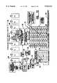
- FIG. 1is a schematic of a preferred embodiment of the apparatus for identifying notes of the present invention.
- FIG. 2is an isometric schematic view of three spot sensing assemblies sensing test spots on a moving note.
- FIG. 3is a schematic view of a spot sensing assembly.
- FIG. 4is a schematic representation demonstrating how a set of sensed data values from a test note is correlated with previously stored value sets for a plurality of note denominations and orientations in the operation of the apparatus of the present invention.
- FIG. 5is a schematic representation demonstrating the calculation of a value representative of a level of correlation between a set of sensed data values and a stored data value set for a particular note type.
- FIG. 6is a schematic representation of data sensed from three spot sensing assemblies and the calculation of a value representative of a level of correlation between the sensed value set and a stored value set.
- FIG. 7is a schematic representation of values stored in a data store of the preferred embodiment of the invention, and how this data is correlated with a sensed value set.
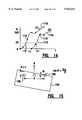
- FIG. 8is a schematic view of a note passing through the apparatus of the present invention in a skewed condition.
- FIG. 9is a schematic representation of data generated by the circuit of the invention responsive to signals from the spot sensing assemblies for the skewed note shown in FIG. 8.
- FIG. 10is a tabular representation of the data shown in FIG. 9 shifted for purposes of calculating a value representative of a level of correlation.
- FIG. 11is a schematic representation demonstrating how sensed value data from a skewed note is correlated with data stored in the data store of the invention.
- FIG. 12is a schematic representation showing the steps in the correlation sequence carried out in the preferred embodiment of the present invention.
- FIG. 13is a schematic view of the control circuit of the preferred embodiment of the present invention.
- FIG. 14is a graphical representation of reflectance signals obtained from transversely disposed spot sensing assemblies for a skewed note, which signals are used by the control circuit to determine an angle of skew.
- FIG. 15is a schematic view of a skewed note and three transversely disposed spot sensing assemblies which correspond to the data graphically shown in FIG. 14.
- the apparatusincludes a note transport 12.
- Transport 12is preferably a belt-type transport that moves sheets such as currency notes one at a time from an entry end 14 to an exit end 16. Sheets such as notes move on the transport 12 in a note direction indicated by Arrow A.
- the apparatus of the present inventionalso includes a plurality of spot sensing assemblies 18.
- the preferred form of the inventionincludes three spot sensing assemblies which are spaced from one another in a direction transverse of the note direction of note movement (see FIG. 3).
- Each of the spot sensing assembliesincludes a reflectance detector, schematically indicated 20.
- Each spot sensing assembly 18also includes a transmission detector schematically indicated 22.
- the reflectance detector 20is in operative connection with, and outputs first signals to, a control circuit schematically indicated 24.
- the transmission detectors 22are also in operative connection with the control circuit 24, and the transmission detectors output second signals thereto.
- Control circuit 24is also in operative connection with a data store schematically indicated 26 which holds stored values in a manner later explained.
- the apparatus of the present inventionmay in certain embodiments also include auxiliary validation sensors schematically indicated 28.
- the auxiliary sensors 28preferably detect properties of passing notes that are not detected by the spot sensing assemblies.
- These auxiliary sensorsmay include, for example, magnetic type sensors or sensors for sensing identification strips on passing notes or sheets.
- the auxiliary sensors 28do not form part of the present invention and are not further discussed herein. It will be understood however, that many types of auxiliary sensors may be used in connection with the present invention and the signals output by such sensors are processed and analyzed in the control circuit 24 through appropriate electronic components.
- Each spot sensing assemblyincludes a reflectance detector 20, which in the preferred form of the invention includes a photocell.
- the reflectance detectors 20are positioned on a first side of a passing note 30 which is shown in phantom in FIG. 2.
- the transport 12moves note 30 past the spot sensing assemblies.
- Each spot sensing assembly 18includes four emitters 32.
- the emitters 32are positioned generally adjacent to, and in surrounding relation of, each reflectance detector 20.
- Each spot sensing assemblyincludes emitters with wavelengths which generally span the visible range of light and infrared.
- each spot sensing assemblyincludes a blue emitter, a green emitter, a red emitter, and an infrared emitter.
- the emittersare light emitting diodes (LEDs) which are selectively operable to produce generally monochromatic light at a particular wavelength. In other embodiments of the invention other types and wavelengths of emitters may be used.
- Each emitter 32 in a spot sensing assemblyis oriented so as to direct and focus radiation onto a test spot schematically indicated 34, which is shown on the adjacent surface of a passing note.
- a test spotschematically indicated 34
- properties of the noteare sampled simultaneously at three test spots 34 which are transversely spaced across the bill.
- radiation from the emitters 32is reflected from each test spot 34 to the reflectance sensor 20 of the spot sensing assembly.
- the reflected lightis passed through a lens 36 adjacent to each reflectance detector to further focus the reflected light thereon.
- each of the transmission detectors 22includes a photocell.
- control circuit 24is operable to selectively actuate each of the emitters 32.
- the control circuitactuates each type emitter in each spot sensing assembly individually, so that only one emitter in a spot sensing assembly is producing radiation at any time.
- the control circuit 24is operative to activate the same type emitter in each of the spot sensing assemblies 18 simultaneously. For example, all the blue emitters in each of the spot sensing assemblies are activated to produce radiation at the same time. Thereafter, all the blue emitters go off and all the green emitters in each of the spot sensing assemblies come on. Thereafter, the green emitters go off and the red emitters come on. When the red emitters go off the infrared emitters come on. The infrared emitters go off and the sequence repeats.
- the emittersmay be activated in a "marquee" style so that the particular type emitter in each assembly is on for a time before it is read, and emitters of the same type are read at different times. This approach has the advantage that it enables the emitters to stabilize before being read by the controller. Of course, the sequence of emitters may be different in other embodiments.
- the emittersradiate individually and in sequence rapidly such that each emitter comes on one time for each test spot 34.
- the test spotspreferably are discrete and each of the emitters direct light onto generally the same spot on the note during one sequence despite the fact that the note is moving.
- each reflectance detector 20produces four first signals for each test spot 34.
- the four first signalsare produced responsive to radiation from the blue, green, red, and infrared emitters respectively.
- each transmission detector 22produces four second signals for each test spot 34. There is one second signal for the radiation transmitted through the test spot from each of the four emitters in the spot sensing assembly.
- the control circuit 24receives each of these first signals and is operative to generate a reflectance value responsive to each signal representative of the magnitude of light reflected by the note 30 from each of the emitters. Likewise, the control circuit 24 is operative to generate transmission values responsive to each of the four second signals from transmission detector 22. Each of the transmission values are representative of transmitted light through the test spot from each emitter. Because there are three spot sensing assemblies 18 spaced transversely across the note, the first circuit is operative to generate 12 reflectance values and 12 transmission values for each row of 3 test spots 34 on the note.
- control circuit 24is operative to actuate the emitters in the spot sensing assemblies very rapidly. This is done so the test spots are maintained discrete and compact. A number of test spots are preferably sensed as a note moves past the three spot sensing assemblies 18 in the transport.
- the transport 12is preferably moved in such a speed that 15 standard U.S. currency notes per second are moved past the spot sensing assemblies.
- 15 standard U.S. currency notes per secondare moved past the spot sensing assemblies.
- different numbers of test spots, data values and note speedsmay be used.
- a fundamental advantage of the present inventionis that the emitters produce radiation which spans the visible range of light as well as infrared. This provides signals which test the validity of the note at a number of different wavelengths in both the transmission and reflectance modes. This enables the gathering of much more data concerning the note image and material properties than prior types of note denominators and validaters.
- a further fundamental advantage of the present inventionis that it is capable of identifying many types of notes in different orientations. As later explained, the preferred form of the present invention does not require that the notes be precisely aligned either in the note direction, or transversely in the note path.
- a note which is delivered to the present invention for identification and validationmay be one of many types.
- the preferred form of the inventionis configured to identify 20 different denominations of notes.
- other embodiments of the inventionmay analyze different numbers of note denominations.
- the notes deliveredthere is no requirement that the notes delivered be oriented a particular way. Therefore, notes may be delivered face up, face down, as well as with the top of the note leading, or with the bottom of the note leading.
- the present inventionmust be able to handle notes delivered in all four orientations.
- a sensed value set 38representative of a set of data sensed from the test note is shown.
- this sensed value setwill generally include a set that is 24 by 29. This is because each row of three test spots generates 24 values (12 reflectance and 12 transmission) and there are generally 29 rows of test spots on the note.
- FIG. 4shows stored value sets 40.
- the stored value setsare produced by the control circuit 24.
- the sensed value set 38 generated from the noteis compared for correlation with each of the stored value sets 40.
- 80 stored value setsare shown. This is representative of the 20 note denominations multiplied by four possible orientations for each note type.
- the apparatusmust determine not only the particular note type (from among 80 possible note types and orientations), but must also determine the note type even though the note position may be shifted either in the direction in which the note is transported or transverse to the note direction, or may be skewed relative to the direction of transport.
- the process by which the control circuit calculates the values representation of the level of correlation between the sensed valued set (which is representative of the reflectance and transmission values from the sensed note) and the stored value sets,is schematically represented in FIG. 5.
- the sensed value set 38is considered to be (x) data.
- the data values in the stored value set indicated 42are considered to be (y) data.
- the level of correlationis 10 calculated in accordance with the equation: ##EQU1## where:
- C xyis the correlation coefficient
- x iis the sensed value from the sensed value set data.
- y iis the corresponding value in the stored value set.
- ⁇ xis the average of the values in the portion of the sensed value set being correlated.
- ⁇ yis the average of the values in the corresponding portion of the stored value set being correlated.
- ⁇ xis the standard deviation of the sensed values in the portion of the sensed value set being correlated.
- ⁇ yis the standard deviation in the corresponding portion of the stored value set.
- a high valueis indicative that the stored value set corresponds to the particular type test note that generates the data in the sensed value set.
- sensed value set 44from a note that is moved past spot sensing assemblies 18.
- sensed value set 44is a matrix that is 24 by 29.
- the lower portion of FIG. 6shows a similarly sized stored value set 46 which is generated by circuit 24 from data in the data store 26 in a manner later explained.
- each setcomprising the three columns of "x" values representing one color and mode in sensed value set 44 is checked for correlation with corresponding values in the three columns of stored value set 46.
- a correlation coefficientis calculated for the values in each triple column set.
- the correlation coefficients for each of the 8 triple column setsare then multiplied together by the control circuit to obtain an overall correlation value indicative of a level of correlation between the sensed value set and the stored value set.
- the correlation coefficient values for reflectance mode valuesare first multiplied together to obtain an overall correlation value for reflectance. Thereafter the same is done for all correlation coefficient values for transmission mode values to obtain an overall value for transmission. These overall values are then multiplied together to calculate a fmal value indicative of correlation of the stored value set and the test note.
- Calculating the transmission and reflectance values separatelyhas the advantage that the individual values can be analyzed individually by the control circuit in accordance with its programming. This may be preferred in some embodiments. For example, high correlation for overall reflectance but not transmission may be indicative of some quality of the note that may warrant taking it out of circulation.
- correlation valuesmay be combined in other ways, such as by wavelength or radiation.
- the combination of correlation values for analysismay differ in other embodiments depending on the notes and properties of interest.
- the present inventionbecause the stored value sets generated are arranged in matrices, can analyze certain physical areas on notes in detail through programming of the control circuit. Thus in embodiments of the invention the manner in which sensed and stored value sets are generated and correlation values calculated may be tailored to note properties and areas of interest.
- the particular type of note passing through the apparatus of the inventionis generally indicated by the stored value set having the highest overall level of correlation with the sensed value set.
- This stored value setcorresponds to one note type, for example, a particular note denomination in a particular orientation.
- control circuit 24is operable to provide an indication not only of the identity of the note type which best correlates with the sensed value set, but also to indicate when the calculated highest level of correlation is below a set threshold which suggests a counterfeit or unacceptable note.
- control circuit of the apparatus of the present inventionmay be configured to include several set thresholds for correlation. These may correspond to notes which are suspect as counterfeit or severely damaged, and notes which merely exhibit signs of wear, age or abuse which make them unacceptable for return to circulation. Because the preferred form of the present invention provides data which accurately identifies notes by denomination despite wear, dirt and extraneous markings, it is possible to make such judgments concerning the quality of a note as well as to identify its type.
- the present inventionalso provides data which may be used advantageously specifically for counterfeit detection purposes.
- the ability of the invention to test both transmission and reflectance across a broad spectrum of radiation, and to compare sensed data to stored values for proper notes,enables the setting of thresholds for particular wavelengths of radiation. Some wavelengths of radiation may provide data more indicative than others of counterfeit or unacceptable notes. This is particularly true in countries which have currency notes that include different color schemes for different denominations.
- the control circuit of the present inventionmay be programmed to abstract and analyze particular abstracted correlation data for this purpose.
- correlation coefficientsare calculated for sets which correspond to 3 columns of data and these correlation coefficients are then combined
- other embodimentsmay use sets comprised of other portions of the sensed data for purposes of calculating the correlation coefficients. These correlation coefficients may then be combined to produce a final value indicative of correlation with the stored value data. For example, correlation values may be calculated between each column or line of sensed data and stored data. These correlation values may then be combined. Alternatively, correlation values based on 12 columns associated with each mode (transmission/reflectance) may be calculated and then the 2 values combined. Alternatively, a single correlation value for all data in the sensed and stored value sets may be calculated.
- the first four rows of sensed data and generally the last three rows of such dataare not correlated with the stored value sets when the bill is transversely aligned in the note path.
- the calculation of the level of correlationis made between sensed value sets and stored value sets comprising 22 rows and 24 columns.
- the first four rows of data sensed from the note and the last at least three rowsare generally used to calculate whether the note is skewed in the transverse direction of the bill path as well as to confirm that the note is the proper length. If the note is skewed the control circuit generates stored value sets by selecting values from the data store which are correspondingly transposed to correspond to the calculated angle of skew. Further, as can be appreciated by those skilled in the art, if a note is "longer" than a proper note, such that it produces data for more test spots than it should, it is identified as a suspect or counterfeit note by the control circuit and is rejected or treated accordingly.
- notes passing the spot sensing assemblies on the transportneed not be aligned either in the note direction or in a transverse direction to be identified.
- the data storeincludes data for all of the identifiable note types at a much closer spacing than the spacing between test spots detected by the spot sensing assemblies as a note passes.
- the datais collected and stored for increments that are one-fourth the spacing between the test spots on a note passing in the transport. Of course, in other embodiments of the invention other increments may be used.
- a sensed value set 38is schematically represented.
- a first template 48is representative of a particular type of note denomination that passes in centered relation relative to the 3 spot sensing assemblies in the transport. As a result, it is indicated in FIG. 7 as having a "0" offset.
- the values shown in first template 48are the 24 transmission and reflectance values for a note of a particular type at increments one-fourth the distance between the test spots on a passing note.
- first template 48would be a matrix of 24 by (29 ⁇ 4) 116 values.
- Stored value sets for comparison to a sensed value setare derived from template 48 by the control circuit by taking the values in every fourth line from the template.
- the data in lines 1, 5, 9, 13, and so oncorrespond to a note in a particular position relative to the direction a note moves in the transport.
- lines 2, 6, 10, 14, and so oncorrespond to the same type of note in another position relative to the note direction.
- control circuitFrom the template 48, the control circuit generates stored value sets corresponding to the particular note type to which template 48 corresponds in varied positions relative to the note transport direction.
- second template 50corresponds to the same note type as note 48.
- Second template 50has reflectance and transmission values for test spots on the note offset a transverse increment from the test spots which produced the values in first template 48.
- the control circuitBy taking every fourth line of values from template 50 the control circuit generates stored value sets for the particular type of note, transversely offset from the centered position and in various positions relative to the direction of note transport.
- Third template 52 shown in FIG. 7corresponds to the same type of note as templates 48 and 50.
- Template 52contains values corresponding to test spots on the note shifted transversely from the zero offset position in an opposed direction from template 50.
- Third template 52is also a matrix of 24 by 116 values. Stored value sets are produced therefrom by the control circuit by abstracting every fourth line of values.
- templatesare provided for test spots at several transversely offset positions. This enables notes to be disposed from the centerline of the note path, as well to have a leading edge that is not aligned with any reference, and still be identified.
- the process of inputting the data necessary to produce the templatesis accomplished in the preferred embodiment during a set up mode of the apparatus.
- stored value datais generated by positioning a note of each type in the transport.
- Datais gathered by each spot sensing assembly from 116 lines of test spots instead of the 29 lines which is the usual number for a sensed note. This can be accomplished by static positioning of the note or, alternatively, by moving the note at a speed which enables the spot sensing assemblies to be sequenced sufficient times to gather the data for storage in the data store.
- the notesare sensed while centered in the transport path as well as disposed transversely from the centered or "zero offset" position, so that the templates for notes that are transversely offset in increments are generated and stored.
- the ability to set up the device by using actual currency and passing it through the transportenables set up of forms of the apparatus in a rapid and reliable fashion. This is desirable where this data must be gathered for twenty notes, each of which has four orientations and several offset positions.
- templatesare produced for four offset positions in each transverse direction from the zero offset position. These templates are offset in increments of one-eighth of an inch. This means that a note passing through the transport may be positioned within one half inch in either transverse direction of the zero offset position and still be accurately identified.
- FIG. 12The process by which the apparatus of the present invention calculates a level of correlation and determines the identity of a note is schematically represented in FIG. 12. It should be understood that in the operation of apparatus 10 the control circuit 24 actuates the emitters of each of the spot sensing assemblies 18 in the sequence on a continuing basis. A note can arrive at any point during the sequence. As the note moves adjacent to and then passes the three spot sensing assemblies 18, the control circuit gathers the data at a step 54. The data gathered is arranged in memory as a matrix of values that is generally 24 by 29. This raw data is represented by matrix 56. Matrix 56 may actually contain more values if the note is skewed. However, for purposes of this initial example, a 24 by 29 matrix will be assumed which corresponds with a non-skewed note.
- control circuit 24is operable to calculate the note length at a step 64. In doing this, the control circuit considers the skew angle, because the spot sensing assemblies will sense more than 29 rows of test spots on a note if the note is skewed.
- the length of the noteis determined based on the number of test spots from which data is received, and the skew angle. The note length is compared to a stored value indicative of the number of test spots for a standard note length, and if the note is "too long" or "too short" control circuit 24 generates a signal indicative of the condition sensed.
- the control circuit 24is operative at a step 66 to generate stored value sets.
- the stored value setsare generated from templates 68.
- the nine templates 68 shownare each a matrix of 24 columns by 116 rows.
- the nine templates 68comprise a master template 70 which corresponds to a note type (one note denomination in a particular orientation).
- Each of the nine templates 68correspond to the note type in each of nine transverse positions in the note path.
- the 116 rows of data in each template 68represent the transmission and reflectance values in increments one-fourth the distance between test spots on a sensed note that is passed through the transport.
- the nine 24 by 116 templates 68comprise the master template 70 which includes all the stored values corresponding to one note type. Because the preferred form of the invention is configured to identify twenty notes in four orientations, there are eighty master templates in the data store in this preferred embodiment.
- other template arrangementsmay be used.
- the control circuit 24is operative in the example shown to produce forty-five stored value sets 72 from the templates 68 in each master template 70. These forty-five stored value sets are shown in a table in FIG. 12. These stored value sets 72 are generated by the control circuit by taking every fourth line from each of the templates 68. The control circuit preferably does this starting with the sixteenth line in each of the templates 68. This is done because, as previously discussed, the first four rows of data taken from the note are used to calculate skew angle, and are generally not used in generating the stored value sets 72 if the note is not skewed. Forty-five stored value sets 72 are generated for each of the eighty templates 70.
- the first row of test spots on the note from which the data would be used for correlation purposes in this examplewould be the fifth row of test spots.
- the control circuittakes the twentieth line and every fourth line thereafter until 22 rows of data are read to generate a 22 by 24 stored value set 72.
- Stored value sets produced in this mannercorrespond to the "zero vertical position" in the table in FIG. 12.
- the control circuit 24is operative to generate stored value sets 72 that are likewise shifted forward in the note direction. This is done by starting with the nineteenth line in each template 78 and taking every fourth line thereafter until 22 values are gathered. This corresponds a shift forward one increment. Stored value sets generated in this manner are the -1/4 stored value sets 72 shown in FIG. 12.
- stored value sets shifted two increments forwardare generated starting with the eighteenth line of data in each of the templates 68 and taking every fourth line thereafter. This corresponds to the -2/4 stored value sets 72 shown in the table in FIG. 12.
- stored value setsare also generated starting with the seventeenth line in each template 68. These correspond to the -3/4 stored value sets 72. Stored value sets starting with the sixteenth line correspond to the -4/4 stored value sets 72 in the table in FIG. 12.
- stored value sets 72are produced starting with the twenty-first, twenty-second, twenty-third, and twenty-fourth values in each of the templates 68. These correspond to the +1/4, +2/4, +3/4, and +4/4 vertical position stored value sets respectively shown in FIG. 12.
- Stored value sets 72are further generated for transverse offset positions. As shown in FIG. 12 stored value sets are produced for transverse offset positions of -1/8", -2/8", +1/8" and +2/8". Thus, the 45 stored value sets 72 represent reflectance and transmission values for one note type shifted forward and backwards in the direction the note moves in the transport, as well as in both transverse directions.
- stored value sets 72are only produced for five transverse positions of the note, rather than nine. This is because the transport of the preferred embodiment and the manner in which the notes are delivered, generally maintain the notes within a quarter inch of the zero offset position. For this reason in the preferred embodiment, it is not necessary to produce additional stored value sets. However, in alternative embodiments where the transverse position of the note may be further disposed from the zero offset position, additional stored value sets may be generated by the control circuit and used for correlation with the sensed value sets.
- the matrix of raw values 56 from a test note that is sensedundergoes a vertical de-skewing step 74 performed by the control circuit 24 when the note is sensed as skewed, as later explained.
- step 74has no effect on the raw data.
- a sensed value set 76which is a 24 by 22 matrix is produced by the control circuit 24 directly from the raw data.
- the control circuit 24is then operative to calculate the level of correlation between the sensed value set 76 and each of the stored value sets 72 in the manner discussed with reference to FIG. 6.
- Each of the correlation valuesis calculated and temporarily stored by the control circuit, which storage is represented by table 78. From all the correlation values calculated for each master template, one value will generally be the highest. Of course, there are eighty master templates and the control circuit is operative to find the highest level of correlation among the forty-five values for each of the 80 master templates. This is represented by a step 80 in FIG. 12.
- the control circuitis then operative at a step 82 to provide an indication of the identity of the note type that produced the highest correlation value and therefore most closely correlates with the sensed value set from the note that passed through the apparatus.
- embodiments of the inventionalso have stored in connection with the control circuit a threshold value which the highest level of correlation calculated must exceed before a note is considered genuine. If the highest level of correlation for all the stored value sets does not exceed this threshold level, then the note is suspect and potentially a counterfeit. Suspect notes of this type may be returned to a customer or held within the apparatus in a designated location. This is done by using a divert mechanism that transports notes to the designated location.
- Alternative embodiments of the inventionmay also be used to segregate notes that are considered in good condition from those that exhibit wear, abuse or soiled conditions. This is accomplished by having stored in connection with the control circuit 24 a further threshold value for correlation which is above the threshold for note genuineness, but below that for notes in suitable condition. Such an intermediate threshold may be used for purposes of segregating bank notes that, while still good, are sufficiently worn or soiled such that they should be removed from circulation.
- a further advantage of the present inventionis that it may provide an indication of note type that includes note orientation. This enables the present invention to be coupled with mechanisms which reorient the note and segregate notes of different denominations. This enables the notes to be collected for bundling or for dispense to a user of the machine in which the apparatus of the present invention is installed.
- the present inventionalso provides capabilities for detecting counterfeit notes. This is achieved because the available data may be selectively processed by the control circuit in ways that are intended to assist in the detection of counterfeit notes. If, for example, it is known that counterfeit currency for a particular country tends to deviate significantly from actual currency either in reflection or transmission of a particular wavelength of radiation, or in a particular region of a note, the level of correlation for this particular wavelength or region of the note may be analyzed by the control circuit individually. Notes which exhibit the properties of a counterfeit may then be identified as suspect even through the overall level of correlation may be marginally acceptable. The particular properties which may distinguish a counterfeit note from a genuine note will depend on a particular currency or other document involved and its properties.
- a further advantage of the preferred embodiment of the present inventionis that notes passing through the apparatus need not be aligned transversely in the note path. Rather, the notes may be skewed such that one of the transverse sides is ahead of the other.
- An example of a note 84 that is skewed relative to the note pathis shown schematically in FIG. 8. Note 84 is shown. with its left side leading. Lines 86 which are superimposed on the note in FIG. 8 show the lines or grid of test spots that would be sampled if the note were aligned in the note path. Lines 88 represent the lines of test spots on the skewed note that are tested by the spot sensing assemblies. Superimposed lines 90 represent where the spot sensing assemblies sense data. Therefore, the intersections of lines 90 and 88 represent a grid of locations where data is gathered by the spot sensing assemblies as the note 84 passes.
- a sensed value set 92 shown in FIG. 9shows the matrix of raw data that is generated as note 84 passes the spot sensing assemblies.
- the spot sensing assembly that is positioned toward the left in FIG. 8begins sensing data from the note before the spot sensing assembly in the center. Further, the spot sensing assembly in the center begins sensing data before the spot sensing assembly on the right.
- the spot sensing assemblies that do not sense the notesense a near zero reflectance value and a large transmission value.
- the spot sensing assembliesstop sensing the note at different times in a manner that is essentially a mirror image of the condition at the leading edge of the note.
- the spot sensing assembliessense data for more than 29 of the transverse lines 90. It will be recalled that 29 rows of test spots were sensed in the prior example for a non-skewed note.
- control circuit 24 of the apparatus of the present inventionis operable to modify the raw sensed value set data 92 represented in FIG. 9 so that it is similar to other sensed value sets for transversely aligned notes.
- the control circuit 24 of the inventionis further operative to produce stored value sets which account for the angle of skew of the note.
- the control circuit 24is first operative to modify the raw sensed value set 92 by transposing the data to eliminate the data points near the leading edge that represent the absence of a note. This involves shifting the values on the right for each type of emitter as shown in FIG. 9, upwardly so that a sensed value set is created in which the sensed note data is present in each position in the 29 rows. Such a modified sensed value set is indicated 94 in FIG. 10.
- a sensed value setwhich is a matrix of 24 by 29 sensed values is produced.
- the modified sensed value set 94"squares up" the sensed data so that it is a similar sensed value set to a transversely aligned note.
- Such "squared up” datais usable by the control circuit for purposes of checking to see if the note sensed is the proper length. If after “squaring up” the raw data the data does not correspond to the length of a proper note, an appropriate indication of a suspect note is given.
- the modification of raw sensed value set 92 to create sensed value set 94does not result in a matrix of values that can be readily correlated with templates for notes that are aligned in the note path. This is because the test spots on skewed note 84 progressively move closer to the right edge of the note as the note passes. The rate at which the test spots on the note migrate toward the right is a function of the skew angle.
- the control circuit 24is operable to generate stored value sets for correlation that account for the angle of skew. This is graphically represented in FIG. 11.
- FIG. 11shows a modified sensed value set schematically indicated 96.
- This modified sensed value set 96for purposes of this example can be envisioned as corresponding to a note like that in FIG. 8 where the note is skewed such that the left side in the frame of reference leads the right side.
- the control circuitis operable based on the calculated angle of skew of the note to take values from different sub-templates 68 in the master template 70 as graphically represented in FIG. 12.
- the values in columns 98, 100, and 102represent the templates similar to sub-templates 68 for a 0" horizontal offset, +1/8" horizontal offset, and 2/8" horizontal offset respectively as shown in FIG. 12.
- the control circuit 24is operative to select a series of values from the 0" offset template represented by column 98.
- the control circuitis then operative to "jump" so as to begin selecting values from column 100 which corresponds to the template 68 for the same note type transposed +1/8" from the 0" offset position.
- the control circuitis operative to begin selecting values from column 102 which is representative of the template for the same note type disposed +2/8" from the 0" offset position.
- control circuit 24begins selecting values from the different templates is determined by the angle of skew.
- Stored value setsare generated for all positions of the note disposed within one-fourth inch of the zero reference in the note path in a similar manner.
- the control circuitmust abstract values from templates 68 for notes that are disposed more than one-fourth inch away from the zero offset position. As can now be appreciated from FIG. 12, this is why there are additional transverse offset templates 68 in each master template 70, even though the note is generally confined to an area plus or minus one-fourth inch from the zero offset position in the note path.
- FIG. 15shows a note 104 which is skewed in a manner similar to note 84 in FIG. 8.
- Note 104has a left side leading a right side in a direction of note travel indicated by Arrow A.
- a spot sensing assembly 106is positioned to the left as shown in FIG. 15.
- a spot sensing assembly 108is positioned to the right as shown in FIG. 16. Both of the spot sensing assemblies are the same and similar to spot sensing assemblies 18 previously discussed.
- Line 110 in FIG. 15is representative of the reflectance values for a first emitter type to have produced radiation which is reflected from note 104 in an amount above a set threshold 112. This threshold is indicated as 20 percent in FIG. 14 which has been found through experimentation to be an acceptable value for this purpose when using U.S. currency notes. Of course other threshold values may be used.
- Data points 114are representative of the actual reflectance values for the particular type emitter in spot sensing assembly 106 which was the first of the emitters to produce a reflectance value above the threshold.
- Line 110is produced by a curve fitting process carried out by control circuit 24 using actual data points 114. This is done through execution of known curve fitting algorithms.
- Line 116is fitted by the control circuit to data points 118.
- Data points 118are representative of the actual reflectance values from the emitter type in spot sensing assembly 108 that corresponds to the emitter that produced data points 114 in spot sensing assembly 106.
- the skew angle of the notemay be calculated. This difference in time in which reflectance values for the same emitter type in each of the spot sensing assemblies crossed the threshold is represented by the quantity At in FIG. 14.
- the distance between spot sensing assemblies 106 and 108is a known fixed quantity. Similarly the speed at which the note moves on the note transport is also known. As shown in FIG. 15 the angle of skew ⁇ can be calculated by the following equation: ##EQU2## where: ⁇ is the angle of skew;
- vis the velocity of the note in the note direction
- .increment.tis the difference in time between when the first emitter in a first spot sensing assembly senses the property of the note crossing the threshold, and when the corresponding emitter in the furthest disposed spot sensing assembly senses the property for that assembly crossing the threshold;
- xis the distance between the spot sensing assemblies 106, 108 for which the time difference is evaluated.
- the angle of skewdetermines the points at which the control circuit begins selecting values from the templates to produce the stored value sets for comparison to the modified sensed value set.
- the angle of skewmay be in either direction which necessitates that the control circuit be enabled to abstract values from templates 68 progressively in either transverse offset direction.
- step 74is the de-skewing step in which the raw sensed value set from the spot sensing assemblies like set 92 in FIG. 9 is "squared up" to produce a modified sensed value set similar to set 94 in FIG. 10.
- this stepis done to produce the sensed value set 76 in FIG. 12 for purposes of correlation.
- step 66the stored value sets are produced by the control circuit by abstracting data from the templates 68 in each master template 70, responsive to the skew angle detected.
- valuesare abstracted from the 0" offset template 68 and the +1/8" offset template 68 to generate the stored value set 72 in the table of stored value sets the 0 vertical and 0" horizontal offset position.
- the control circuit 24abstracts values from the -2/8" and -1/8" horizontal offset templates 68, and so on. It can be appreciated that the selection process 51 executed by the control circuit 24 to generate the stored value sets for comparison with the sensed value set 76 can be visualized as a matter of shifting left-right among the templates 68 and up and down within the templates 68 to produce the various stored value sets 72 shown in the table positions in FIG. 12.
- the control circuit 24 of the preferred embodimentis schematically represented in FIG. 13.
- the control circuit 24includes an optical sensors and electronics component 120.
- the optical sensors and electronics componentincludes the spot sensing assemblies 18 which produce the first and second signals which cause the control circuit 24 to generate the reflectance and transmission values.
- the control circuitfurther includes a scanning control subassembly 122 which is in connection with the optical sensors and electronics component 120.
- the scanning control subassembly 122actuates the emitters in the sequence to produce the synchronized first and second signals which correspond to each emitter type.
- a multiplexer and analog to digital (A/D) converter component 124is operative to receive the first and second signals from the spot sensing assemblies and to produce the raw reflectance and transmission values and to direct them to generate the sensed value set for each sensed note.
- the control circuit 24further includes an auxiliary sensors subassembly 126.
- the auxiliary sensors subassemblycorresponds to the auxiliary sensors 28 previously discussed. These auxiliary sensors are preferably a type particularly tailored to the document or note type being sensed.
- a module controller 128is operative to receive data from and to control the operation of the other components of the system.
- the controller 128is in connection with an angle encoder subassembly 130.
- the angle encoder subassembly 130is operative to determine the skew angle of a note from the initial emitter signals as the note is sensed in the manner previously discussed.
- the control circuit 24further includes a communications subassembly 132 which is operative to transmit signals to and from the controller 128.
- the communications subassemblytransmits information to and from a larger system of which the apparatus is a part. It also delivers signals to and from input and output devices.
- the controller 128is in communication with a plurality of calculator modules 134.
- Each calculator module 134includes a digital signal processor 136.
- Each digital signal processor 136is in operative connection with a static random access memory 138.
- the memories 138hold the stored values which are used to determine the level of correlation between the sensed value set and the generated stored value sets.
- Each memory 138preferably holds a different group of the master templates 70.
- Each calculator module 134further includes a calculator controller 140.
- the calculator controllersare operative to produce the stored value sets from the templates in the memories 138. This is done based on angle of skew data provided by the controller 128.
- the calculator controllersare further operative to cause their associated digital signal processor to calculate the correlation values between the data values in the sensed value set and the stored value sets.
- the calculator controllersare further operative to control the associated digital signal processor to calculate the overall correlation coefficient for each stored value set, and to indicate the highest correlation value for the master templates handled by the particular calculator module.
- control circuit 24enables rapidly carrying out large numbers of calculations which are necessary to generate the stored value sets and to determine the correlation values for the sensed value set and all the stored value sets.
- the control circuit 24has the advantage that each of the digital signal processors operates in parallel on the master templates stored in its associated memory.
- processing capabilities of control circuit 24may be increased by adding additional calculator and modules 134 to generate and correlate additional stored value sets. This enables correlating selective or additional sensed values with stored data.
- the controller 128operates the scanning control subassembly 122 to sequence the emitters in the spot sensing assemblies, which are included in the optical sensors and electronics subassembly 120.
- the first and second signals corresponding to reflectance and transmission from each emitterare delivered to the multiplexer and A/D converter 124 which delivers digital reflectance and transmission values corresponding to each emitter.
- the multiplexer and A/D converter 124also receives signals from the auxiliary sensors and electronics subassembly 126 and delivers appropriate signals from these to the controller 128 as well.
- the controller 128is operable to sense a note entering into proximity with the spot sensing assemblies and to produce the raw sensed value set.
- the angle encoder subassembly 130is operative to determine the angle of skew from the raw sensed value set and to deliver the information to the controller 128.
- the controller 128is further operative to modify the raw sensed value set and to deliver the modified sensed value set and the angle of skew data to each of the calculator modules 134.
- the controller 128is operative to determine the note length from the modified sensed value set and compare it to the length for a standard note based on the number of test spots obtained. If the sensed note does not have the proper length a signal indicative thereof is generated, and further processing for that note is not conducted.
- Each calculator module 134is operative to generate stored value sets from the stored values in the master templates in memories 138 based on the angle of skew.
- the calculator modulesare further operative to calculate the correlation coefficient values for the modified sensed value set and each of the generated stored value sets.
- Each calculator modulestores and communicates to the controller 128 the calculated overall correlation coefficient value for each of the generated stored value sets.
- Each calculator moduleprovides this information along with the data identifying the master template which was used to generate the stored value sets, to controller 128, along with other selected correlation data that the calculator modules may have been programmed to provide.
- the controlleris operative to receive the signals from each of the calculator modules and to determine which master template produced the highest level of correlation with the sensed value set.
- the controller moduleis further operative to determine if the correlation value which is the highest, is over a first threshold which indicates that the level of correlation is likely to be indicative of the note type associated with the particular master template.
- the controller 128then transmits signals to the communication subassembly 132 indicative of the note type identified or signals indicative that the note identified is suspect because its highest correlation level is not above the threshold.
- the controller 128may test to determine if the correlation value exceeds other thresholds and transmit signals indicative of the fitness of the note for further use, or other signals relating to the genuineness or suspect character of the note.
- the communication subassembly 132transmits signals to a communications bus connected to the apparatus of the present invention and to other devices and systems which are operative to further process the note or provide information about the note.
- control circuit 24While in the preferred embodiment of the control circuit 24 is adapted to performing the calculating functions required for identifying the types of notes, in other embodiments other control circuit configurations may be used. Further, in the preferred form of the control circuit 24 the memories 38 which make up the data store may be programmed through the apparatus. This may be done in a setup mode as discussed by selectively positioning sample notes and moving them in controlled relation adjacent the spot sensing assemblies to gather the data necessary to produce the master templates.
- the module controller 128control the operation of the note transport to move the sample notes at a speed which will enable gathering data at all the desired locations on the note.
- the controller 128may also be programmed in the setup mode to receive signals indicative of the note type, and the transverse offset positions of the note used to provide template data in the memories 138 which comprise the data store.
- the stored datamay be produced in a different apparatus and loaded into the memories 138 through the controller 128 or from another source.
- stored valuesmay be gathered from static analysis of sample notes.
- the optical sensors and electronic subassembly 120further includes a compensator circuit that facilitates calibration of the spot sensing assemblies.
- the optical sensors and electronic subassemblyis calibrated using a selected standard grade of white paper which is passed through the note transport adjacent to the spot sensing assemblies.
- the optical sensors and electronic subassembly 120is operative to adjust the amount of radiation generated by each of emitters to produce a preset output. This ensures that the level of radiation produced by each of the emitters is sufficient to correlate accurately with the stored value sets that are produced.
- other types or reference materialmay be used for purposes of calibration.
- Periodic calibration of the optical sensors and electronic subassembly 120ensures that changes in the emitters over time or changes in the optical path due to accumulation of dust or other contaminants, will not adversely impact the accuracy of the apparatus. Due to the nature of light emitting diodes (LEDs) used for the emitters and the nature of the control circuitry which generally responds to relative values rather than absolute values, in the preferred embodiment calibration is required infrequently.
- LEDslight emitting diodes
- the preferred embodiment of the apparatus of the present inventionpresents the advantage that it is capable of identifying notes that are presented in any orientation. It further operates to identify notes at high speed and without the need to have the notes precisely aligned or positioned with respect to a frame of reference.
- the preferred embodiment of the present mventionfurther has the advantage that it is readily adaptable to different types of currency notes or other document types, and can be used to detect suspect or counterfeit notes.
- the preferred form of the present inventionis also readily adaptable to different types of notes, and may be programmed to simultaneously identify notes from different countries which have different properties and which are different sizes. Further, due to the data available, the preferred form of the present invention may be programmed to analyze certain sensed values in greater detail to point out characteristics that may be associated with unsuitably worn or counterfeit notes.
- the preferred embodiment of the present inventionfurther presents the advantage that it is rapidly configured, programmed, readily calibrated and does not require frequent adjustment.
- the new universal bank note denominator and validater apparatus of the present inventionachieves the above stated objectives, eliminates difficulties encountered in the use of prior devices and systems, solves problems, and attains the desirable results described herein.
- any feature described as a means for performing a functionshall be construed as encompassing any means capable of performing the recited function and shall not be deemed limited to the particular means shown as performing the recited function in the foregoing description, or mere equivalents.
Landscapes
- Health & Medical Sciences (AREA)
- General Health & Medical Sciences (AREA)
- Toxicology (AREA)
- Physics & Mathematics (AREA)
- General Physics & Mathematics (AREA)
- Investigating Or Analysing Materials By Optical Means (AREA)
- Inspection Of Paper Currency And Valuable Securities (AREA)
- Image Analysis (AREA)
Abstract
Description
Claims (77)
Priority Applications (30)
| Application Number | Priority Date | Filing Date | Title |
|---|---|---|---|
| US08/749,260US5923413A (en) | 1996-11-15 | 1996-11-15 | Universal bank note denominator and validator |
| DE69739506TDE69739506D1 (en) | 1996-11-15 | 1997-11-14 | UNIVERSAL BANKNOTE VALUE DETECTOR AND EVALUATOR |
| PCT/US1997/021790WO1998021697A2 (en) | 1996-11-15 | 1997-11-14 | Universal bank note denominator and validator |
| CA002387415ACA2387415C (en) | 1996-11-15 | 1997-11-14 | Universal bank note denominator and validator |
| EP97949659AEP1021788B1 (en) | 1996-11-15 | 1997-11-14 | Universal bank note denominator and validator |
| CNB971808937ACN1160659C (en) | 1996-11-15 | 1997-11-14 | Universal banknote validator and validator |
| CA002271071ACA2271071C (en) | 1996-11-15 | 1997-11-14 | Universal bank note denominator and validator |
| ES97949659TES2328752T3 (en) | 1996-11-15 | 1997-11-14 | UNIVERSAL DEVICE TO DETERMINE THE NAME AND VALIDATE THE BANK TICKETS. |
| RU99112497/09ARU2183350C2 (en) | 1996-11-15 | 1997-11-14 | Universal device for estimating tenor and authenticity of banknote |
| BR9713352-3ABR9713352A (en) | 1996-11-15 | 1997-11-14 | Universal banknote denominator and validator |
| US09/135,384US6101266A (en) | 1996-11-15 | 1998-08-17 | Apparatus and method of determining conditions of bank notes |
| US09/375,960US6486464B1 (en) | 1996-11-15 | 1999-08-17 | Double sheet detector method for automated transaction machine |
| US09/633,486US6573983B1 (en) | 1996-11-15 | 2000-08-07 | Apparatus and method for processing bank notes and other documents in an automated banking machine |
| US09/911,329US6607081B2 (en) | 1996-11-15 | 2001-07-23 | Automated transaction machine system |
| US10/426,068US6774986B2 (en) | 1996-11-15 | 2003-04-29 | Apparatus and method for correlating a suspect note deposited in an automated banking machine with the depositor |
| US10/439,803US6726097B2 (en) | 1996-11-15 | 2003-05-16 | Automated transaction machine system |
| US10/449,096US7494046B2 (en) | 1996-11-15 | 2003-05-30 | Automated transaction machine system |
| US10/852,795US7513413B2 (en) | 1996-11-15 | 2004-05-25 | Correlation of suspect currency note received by ATM to the note depositor |
| US10/944,579US7090122B1 (en) | 1996-11-15 | 2004-09-16 | Check accepting and cash dispensing automated banking machine system and method |
| US11/214,461US7584883B2 (en) | 1996-11-15 | 2005-08-29 | Check cashing automated banking machine |
| US11/228,684US7513417B2 (en) | 1996-11-15 | 2005-09-16 | Automated banking machine |
| US11/270,363US7559460B2 (en) | 1996-11-15 | 2005-11-08 | Automated banking machine |
| US11/324,835US7588182B2 (en) | 1996-11-15 | 2006-01-03 | Automated banking machine |
| US11/324,903US7591414B2 (en) | 1996-11-15 | 2006-01-03 | Automated banking machine |
| US11/502,302US7284695B1 (en) | 1996-11-15 | 2006-08-10 | Check accepting and cash dispensing automated banking machine system and method |
| US12/380,105US7891554B2 (en) | 1996-11-15 | 2009-02-23 | Automated transaction machine system |
| US12/584,307US7798398B2 (en) | 1996-11-15 | 2009-09-02 | Check cashing automated banking machine |
| US12/586,461US8025218B2 (en) | 1996-11-15 | 2009-09-21 | Automated banking machine |
| US12/807,987US8002177B2 (en) | 1996-11-15 | 2010-09-16 | Check cashing automated banking machine controlled responsive to data bearing records |
| US13/200,265US8474697B2 (en) | 1996-11-15 | 2011-09-22 | Automated banking machine |
Applications Claiming Priority (1)
| Application Number | Priority Date | Filing Date | Title |
|---|---|---|---|
| US08/749,260US5923413A (en) | 1996-11-15 | 1996-11-15 | Universal bank note denominator and validator |
Related Parent Applications (1)
| Application Number | Title | Priority Date | Filing Date |
|---|---|---|---|
| US09/992,357Continuation-In-PartUS6783061B2 (en) | 1996-11-15 | 2001-11-13 | Storing information concerning suspect currency notes received in an ATM |
Related Child Applications (2)
| Application Number | Title | Priority Date | Filing Date |
|---|---|---|---|
| US08/980,467Continuation-In-PartUS6273413B1 (en) | 1996-11-15 | 1997-11-28 | Automated banking machine with sheet directing apparatus |
| US09/135,384Continuation-In-PartUS6101266A (en) | 1996-11-15 | 1998-08-17 | Apparatus and method of determining conditions of bank notes |
Publications (1)
| Publication Number | Publication Date |
|---|---|
| US5923413Atrue US5923413A (en) | 1999-07-13 |
Family
ID=25012994
Family Applications (2)
| Application Number | Title | Priority Date | Filing Date |
|---|---|---|---|
| US08/749,260Expired - LifetimeUS5923413A (en) | 1996-11-15 | 1996-11-15 | Universal bank note denominator and validator |
| US09/135,384Expired - LifetimeUS6101266A (en) | 1996-11-15 | 1998-08-17 | Apparatus and method of determining conditions of bank notes |
Family Applications After (1)
| Application Number | Title | Priority Date | Filing Date |
|---|---|---|---|
| US09/135,384Expired - LifetimeUS6101266A (en) | 1996-11-15 | 1998-08-17 | Apparatus and method of determining conditions of bank notes |
Country Status (9)
| Country | Link |
|---|---|
| US (2) | US5923413A (en) |
| EP (1) | EP1021788B1 (en) |
| CN (1) | CN1160659C (en) |
| BR (1) | BR9713352A (en) |
| CA (1) | CA2271071C (en) |
| DE (1) | DE69739506D1 (en) |
| ES (1) | ES2328752T3 (en) |
| RU (1) | RU2183350C2 (en) |
| WO (1) | WO1998021697A2 (en) |
Cited By (99)
| Publication number | Priority date | Publication date | Assignee | Title |
|---|---|---|---|---|
| WO1999028846A1 (en) | 1997-11-28 | 1999-06-10 | Diebold, Incorporated | Automated banking machine with self auditing capabilities and system |
| US6064058A (en)* | 1998-05-15 | 2000-05-16 | Hung-Yi Wu | Printed paper identification system |
| US6101266A (en) | 1996-11-15 | 2000-08-08 | Diebold, Incorporated | Apparatus and method of determining conditions of bank notes |
| US6232124B1 (en) | 1996-05-06 | 2001-05-15 | Verification Technologies, Inc. | Automated fingerprint methods and chemistry for product authentication and monitoring |
| US6257389B1 (en)* | 1998-02-05 | 2001-07-10 | Ascom Autelca Ag | Device for examining securities |
| US20010035603A1 (en)* | 2000-02-08 | 2001-11-01 | Graves Bradford T. | Method and apparatus for detecting doubled bills in a currency handling device |
| US6331000B1 (en)* | 1998-09-17 | 2001-12-18 | Diebold, Incorporated | Currency recycling system and method for automated banking machine |
| WO2002009043A1 (en)* | 2000-07-20 | 2002-01-31 | Currency Systems International, Inc. | Note-specific currency processing |
| WO2002017217A1 (en)* | 2000-08-18 | 2002-02-28 | Physical Optics Corporation | Scanner with waveguide for scanning paper currency |
| US6393140B1 (en)* | 1997-04-16 | 2002-05-21 | Nippon Conlux Co., Ltd. | Paper-like piece identifying method and device |
| US6486464B1 (en)* | 1996-11-15 | 2002-11-26 | Diebold, Incorporated | Double sheet detector method for automated transaction machine |
| US6490030B1 (en) | 1999-01-18 | 2002-12-03 | Verification Technologies, Inc. | Portable product authentication device |
| US20030009420A1 (en)* | 2001-07-05 | 2003-01-09 | Jones John E. | Automated payment system and method |
| US6512580B1 (en) | 1999-10-27 | 2003-01-28 | Verification Technologies, Inc. | Method and apparatus for portable product authentication |
| US20030043365A1 (en)* | 2001-09-06 | 2003-03-06 | Ncr Corporation | Optical media detection system |
| US6538743B2 (en)* | 1999-06-11 | 2003-03-25 | Metso Automation Oy | Method and apparatus for measuring properties of paper web |
| US20030077752A1 (en)* | 1998-12-10 | 2003-04-24 | Myung-Sam Cho | Factor VIII glycoforms |
| US20030081197A1 (en)* | 2001-08-06 | 2003-05-01 | Zoladz Edward M. | Document validator subassembly |
| US6573983B1 (en) | 1996-11-15 | 2003-06-03 | Diebold, Incorporated | Apparatus and method for processing bank notes and other documents in an automated banking machine |
| WO2003050772A1 (en)* | 2001-12-13 | 2003-06-19 | Kabushiki Kaisha Nippon Conlux | Banknote identifying machine and banknote identifying method |
| US6589626B2 (en) | 2000-06-30 | 2003-07-08 | Verification Technologies, Inc. | Copy-protected optical media and method of manufacture thereof |
| US20030139994A1 (en)* | 2002-01-22 | 2003-07-24 | Jones John E. | Financial institution system |
| WO2003077187A1 (en) | 2002-03-11 | 2003-09-18 | Digital Verification Ltd. | Currency verification |
| US6638593B2 (en) | 2000-06-30 | 2003-10-28 | Verification Technologies, Inc. | Copy-protected optical media and method of manufacture thereof |
| US20040084277A1 (en)* | 2002-11-06 | 2004-05-06 | Blair Ronald Bruce | Vignette inspection system |
| US6734953B2 (en)* | 2000-06-12 | 2004-05-11 | Glory Ltd | Bank note processing machine |
| US6741351B2 (en)* | 2001-06-07 | 2004-05-25 | Koninklijke Philips Electronics N.V. | LED luminaire with light sensor configurations for optical feedback |
| US6741336B2 (en)* | 2000-06-03 | 2004-05-25 | Bundesruckerai Gmbh | Sensor for authenticity identification of signets on documents |
| US20040153408A1 (en)* | 2002-09-25 | 2004-08-05 | Jones John E. | Financial document processing system |
| US20040245708A1 (en)* | 2003-03-11 | 2004-12-09 | Toru Takeuchi | Banknote storing with condition detection apparatus and method |
| US20040260650A1 (en)* | 2003-06-12 | 2004-12-23 | Yuji Nagaya | Bill transaction system |
| US20050183927A1 (en)* | 2001-12-19 | 2005-08-25 | Scan Coin Industries Ab | Apparatus for receiving and distributing cash |
| US20050207634A1 (en)* | 1996-11-27 | 2005-09-22 | Jones John E | Automated document processing system and method using image scanning |
| US20050236037A1 (en)* | 2004-04-23 | 2005-10-27 | Kwang-Soon Ahn | Dye-sensitized solar cell module |
| US20050286751A1 (en)* | 2004-06-29 | 2005-12-29 | Sanyo Electric Co., Ltd. | Apparatus for discriminating paper-like sheets and method for discriminating same |
| US20060010071A1 (en)* | 2001-09-27 | 2006-01-12 | Jones John E | Document processing system using full image scanning |
| EP1208518A4 (en)* | 1999-07-26 | 2006-01-18 | Cummins Allison Corp | Currency handling system employing an infrared authenticating system |
| US20060037834A1 (en)* | 2002-12-27 | 2006-02-23 | Tokimi Nago | Optical sensing device for detecting optical features of valuable papers |
| US20060140468A1 (en)* | 2002-09-17 | 2006-06-29 | Giesecke & Devrient Gmbh | Method and testing device for testing valuable documents |
| US7079230B1 (en) | 1999-07-16 | 2006-07-18 | Sun Chemical B.V. | Portable authentication device and method of authenticating products or product packaging |
| US7090122B1 (en)* | 1996-11-15 | 2006-08-15 | Diebold, Incorporated | Check accepting and cash dispensing automated banking machine system and method |
| US7124944B2 (en) | 2000-06-30 | 2006-10-24 | Verification Technologies, Inc. | Product packaging including digital data |
| US20070062783A1 (en)* | 2005-09-17 | 2007-03-22 | Hill Timothy W | Coin handling equipment |
| US20070076939A1 (en)* | 1996-05-13 | 2007-04-05 | Cummins-Allison Corp. | Automated document processing system using full image scanning |
| US20070187485A1 (en)* | 2006-02-10 | 2007-08-16 | Aas Per C | Cash handling |
| RU2308088C2 (en)* | 2005-10-06 | 2007-10-10 | Общество с ограниченной ответственностью Фирма "ДАТА-ЦЕНТР" (ООО Фирма "ДАТА-ЦЕНТР") | Method for setting modes of operation and information input into a machine for sorting banknotes |
| US20070295812A1 (en)* | 2006-06-23 | 2007-12-27 | Thomas Mazowiesky | Validator linear array |
| US20080041941A1 (en)* | 2004-08-23 | 2008-02-21 | Mehdi Talwerdi | Apparatus and Method for Secure Identification of Security Features in Value Items |
| US20080130980A1 (en)* | 2006-12-04 | 2008-06-05 | Gildersleeve Mary E | Paper currency note scanner and identifier for use by visually impaired individuals |
| EP1950712A1 (en) | 1997-11-28 | 2008-07-30 | Diebold, Incorporated | Automated banking machine with self auditing capabilities and system |
| US7486790B1 (en) | 2000-06-30 | 2009-02-03 | Verification Technologies, Inc. | Method and apparatus for controlling access to storage media |
| US7513417B2 (en) | 1996-11-15 | 2009-04-07 | Diebold, Incorporated | Automated banking machine |
| WO2009042876A3 (en)* | 2007-09-26 | 2009-06-11 | Mei Inc | Document validator subassembly |
| US7559460B2 (en) | 1996-11-15 | 2009-07-14 | Diebold Incorporated | Automated banking machine |
| US7584883B2 (en) | 1996-11-15 | 2009-09-08 | Diebold, Incorporated | Check cashing automated banking machine |
| US7611048B1 (en) | 1999-11-30 | 2009-11-03 | Diebold, Incorporated | Check accepting and cash dispensing automated banking machine system and method |
| US7660415B2 (en) | 2000-08-03 | 2010-02-09 | Selinfreund Richard H | Method and apparatus for controlling access to storage media |
| US20100032351A1 (en)* | 2006-09-08 | 2010-02-11 | Alfred Schmidt | Method for destroying banknotes |
| US20100112923A1 (en)* | 2005-07-17 | 2010-05-06 | Timothy William Hill | Coin handling equipment |
| US20100128964A1 (en)* | 2008-11-25 | 2010-05-27 | Ronald Bruce Blair | Sequenced Illumination |
| US20100259749A1 (en)* | 2006-08-22 | 2010-10-14 | Mei, Inc | Optical detector arrangement for document acceptor |
| US7819309B1 (en) | 1999-11-30 | 2010-10-26 | Diebold, Incorporated | Check accepting and cash dispensing automated banking machine system and method |
| US7903863B2 (en) | 2001-09-27 | 2011-03-08 | Cummins-Allison Corp. | Currency bill tracking system |
| US20110174051A1 (en)* | 2008-09-19 | 2011-07-21 | Giesecke & Devrient Gmbh | Calibration of a sensor for processing value documents |
| CN1835023B (en)* | 2005-03-17 | 2011-08-03 | 冲电气工业株式会社 | Medium distinguishing device |
| US8162125B1 (en) | 1996-05-29 | 2012-04-24 | Cummins-Allison Corp. | Apparatus and system for imaging currency bills and financial documents and method for using the same |
| US8204293B2 (en) | 2007-03-09 | 2012-06-19 | Cummins-Allison Corp. | Document imaging and processing system |
| JP2012194601A (en)* | 2011-03-14 | 2012-10-11 | Dainippon Printing Co Ltd | Individual identification device, individual identification method and program |
| US8391583B1 (en)* | 2009-04-15 | 2013-03-05 | Cummins-Allison Corp. | Apparatus and system for imaging currency bills and financial documents and method for using the same |
| US8401268B1 (en) | 2007-03-09 | 2013-03-19 | Cummins-Allison Corp. | Optical imaging sensor for a document processing device |
| US8417017B1 (en) | 2007-03-09 | 2013-04-09 | Cummins-Allison Corp. | Apparatus and system for imaging currency bills and financial documents and method for using the same |
| US8428332B1 (en) | 2001-09-27 | 2013-04-23 | Cummins-Allison Corp. | Apparatus and system for imaging currency bills and financial documents and method for using the same |
| US8433123B1 (en) | 2001-09-27 | 2013-04-30 | Cummins-Allison Corp. | Apparatus and system for imaging currency bills and financial documents and method for using the same |
| US8437528B1 (en) | 2009-04-15 | 2013-05-07 | Cummins-Allison Corp. | Apparatus and system for imaging currency bills and financial documents and method for using the same |
| US8437530B1 (en) | 2001-09-27 | 2013-05-07 | Cummins-Allison Corp. | Apparatus and system for imaging currency bills and financial documents and method for using the same |
| US8437529B1 (en) | 2001-09-27 | 2013-05-07 | Cummins-Allison Corp. | Apparatus and system for imaging currency bills and financial documents and method for using the same |
| US8459436B2 (en) | 2008-10-29 | 2013-06-11 | Cummins-Allison Corp. | System and method for processing currency bills and tickets |
| US8478020B1 (en) | 1996-11-27 | 2013-07-02 | Cummins-Allison Corp. | Apparatus and system for imaging currency bills and financial documents and method for using the same |
| US8538123B1 (en) | 2007-03-09 | 2013-09-17 | Cummins-Allison Corp. | Apparatus and system for imaging currency bills and financial documents and method for using the same |
| US8547537B2 (en)* | 2009-10-15 | 2013-10-01 | Authentix, Inc. | Object authentication |
| WO2013151560A1 (en)* | 2012-04-06 | 2013-10-10 | Authentix, Inc. | Skew angle determination |
| US8627939B1 (en) | 2002-09-25 | 2014-01-14 | Cummins-Allison Corp. | Apparatus and system for imaging currency bills and financial documents and method for using the same |
| US8682038B2 (en) | 2008-11-25 | 2014-03-25 | De La Rue North America Inc. | Determining document fitness using illumination |
| US8749767B2 (en) | 2009-09-02 | 2014-06-10 | De La Rue North America Inc. | Systems and methods for detecting tape on a document |
| US8929640B1 (en) | 2009-04-15 | 2015-01-06 | Cummins-Allison Corp. | Apparatus and system for imaging currency bills and financial documents and method for using the same |
| US8944234B1 (en) | 2001-09-27 | 2015-02-03 | Cummins-Allison Corp. | Apparatus and system for imaging currency bills and financial documents and method for using the same |
| US9053596B2 (en) | 2012-07-31 | 2015-06-09 | De La Rue North America Inc. | Systems and methods for spectral authentication of a feature of a document |
| US9141876B1 (en) | 2013-02-22 | 2015-09-22 | Cummins-Allison Corp. | Apparatus and system for processing currency bills and financial documents and method for using the same |
| US9218704B2 (en) | 2011-11-01 | 2015-12-22 | Pepsico, Inc. | Dispensing system and user interface |
| US9721060B2 (en) | 2011-04-22 | 2017-08-01 | Pepsico, Inc. | Beverage dispensing system with social media capabilities |
| US20170309105A1 (en)* | 2016-04-25 | 2017-10-26 | Leadot Innovation, Inc. | Method of Determining Currency and Denomination of an Inserted Bill in a Bill Acceptor Having a Single Slot and Related Device |
| US9818249B1 (en) | 2002-09-04 | 2017-11-14 | Copilot Ventures Fund Iii Llc | Authentication method and system |
| EP3279875A1 (en)* | 2016-08-02 | 2018-02-07 | NGZ Geldzählmaschinengesellschaft mbH & Co. KG | Pollution detector, coin sorting machine and method for contamination detection for coins |
| EP3284706A1 (en) | 2006-11-10 | 2018-02-21 | Diebold Nixdorf, Incorporated | System controlled by data bearing records including automated banking |
| US9910122B2 (en)* | 2012-07-06 | 2018-03-06 | Giesecke+Devrient Currency Technology Gmbh | Calibration of a magnetic sensor |
| US20180157613A1 (en)* | 2015-04-28 | 2018-06-07 | Giesecke+Devrient Currency Technology Gmbh | Value document handling apparatus having a data communication system and method for distributing sensor data in a value document handling apparatus |
| US10762736B2 (en) | 2014-05-29 | 2020-09-01 | Ncr Corporation | Currency validation |
| US11144172B2 (en) | 2013-11-13 | 2021-10-12 | Huawei Technologies Co., Ltd. | Launching application task based on single user input and preset condition |
| CN115140548A (en)* | 2022-09-05 | 2022-10-04 | 裕克施乐塑料制品(太仓)有限公司 | Full-automatic all-in-one machine integrating blanking, stacking tray and CCD detection |
Families Citing this family (60)
| Publication number | Priority date | Publication date | Assignee | Title |
|---|---|---|---|---|
| US6269169B1 (en)* | 1998-07-17 | 2001-07-31 | Imaging Automation, Inc. | Secure document reader and method therefor |
| JP3773689B2 (en)* | 1999-03-17 | 2006-05-10 | 株式会社日本コンラックス | Coin inspection method and apparatus |
| US6731785B1 (en)* | 1999-07-26 | 2004-05-04 | Cummins-Allison Corp. | Currency handling system employing an infrared authenticating system |
| DE19958048A1 (en)* | 1999-12-03 | 2001-06-07 | Giesecke & Devrient Gmbh | Device and method for checking the authenticity of banknotes |
| DE10000030A1 (en)* | 2000-01-03 | 2001-07-05 | Giesecke & Devrient Gmbh | Camera system for processing documents |
| US6473165B1 (en)* | 2000-01-21 | 2002-10-29 | Flex Products, Inc. | Automated verification systems and methods for use with optical interference devices |
| DE10005514A1 (en)* | 2000-02-07 | 2001-08-09 | Giesecke & Devrient Gmbh | Method and device for checking banknotes and the state of their use possibly impairing their usefulness through dirt and stains includes graded lenses in front of sensors to map a 1:1 image on the sensors of banknotes to be checked |
| GB2361765A (en)* | 2000-04-28 | 2001-10-31 | Ncr Int Inc | Media validation by diffusely reflected light |
| US6772948B2 (en)* | 2000-12-28 | 2004-08-10 | Ericsson Inc. | Manual bar code scanner with improved reliability |
| RU2219580C2 (en)* | 2001-06-25 | 2003-12-20 | ОАО Концерн "Российские защитные технологии" | Securities authenticating device |
| KR20030051250A (en)* | 2001-12-13 | 2003-06-25 | 오므론 가부시키가이샤 | Method and Apparatus of True or False Documents Distinction |
| EP1321904B2 (en)† | 2001-12-20 | 2020-04-08 | Crane Payment Innovations, Inc. | Apparatus for sensing optical characteristics of a banknote |
| US6838687B2 (en)* | 2002-04-11 | 2005-01-04 | Hewlett-Packard Development Company, L.P. | Identification of recording media |
| WO2004047032A1 (en)* | 2002-11-19 | 2004-06-03 | Guardian Sure Scan Limited | Method and apparatus for verifying the authenticity of bank notes |
| EP1429296A1 (en)* | 2002-12-13 | 2004-06-16 | Mars, Inc. | Apparatus for classifying banknotes |
| EP1429297A1 (en)* | 2002-12-13 | 2004-06-16 | Mars, Inc. | Apparatus for classifying banknotes |
| DE10259288A1 (en)* | 2002-12-18 | 2004-07-22 | Giesecke & Devrient Gmbh | Method and device for checking banknotes |
| JP2004227093A (en)* | 2003-01-20 | 2004-08-12 | Asahi Seiko Kk | Banknote detector in banknote recognition device |
| CA2733303C (en)* | 2003-03-10 | 2014-12-23 | Diebold, Incorporated | Cash dispensing automated banking machine with service monitor |
| WO2004081885A2 (en) | 2003-03-10 | 2004-09-23 | Diebold, Incorporated | Cash dispensing automated banking machine deposit accepting system and method |
| ATE396942T1 (en)* | 2003-03-12 | 2008-06-15 | Rue De Int Ltd | OPTICAL DUAL FEED DETECTION |
| DE10317397A1 (en)* | 2003-04-15 | 2004-11-04 | Scheidt & Bachmann Gmbh | Device for accepting coins |
| JP2004326624A (en)* | 2003-04-25 | 2004-11-18 | Aruze Corp | Identification sensor |
| US20060272921A1 (en)* | 2003-06-25 | 2006-12-07 | International Currency Technologies Corporation | Banknote acceptor using ultraviolet ray for verification |
| US20040262121A1 (en)* | 2003-06-25 | 2004-12-30 | Tien-Yuan Chien | Banknote acceptor |
| DE10335147A1 (en)* | 2003-07-31 | 2005-03-03 | Giesecke & Devrient Gmbh | Method and apparatus for determining the status of banknotes |
| FR2859806B1 (en)* | 2003-09-12 | 2005-12-23 | Sagem | APPARATUS FOR ANALYZING DOCUMENTS, IN PARTICULAR BANK NOTES |
| US7366337B2 (en)* | 2004-02-11 | 2008-04-29 | Sbc Knowledge Ventures, L.P. | Personal bill denomination reader |
| KR101297702B1 (en)* | 2004-03-08 | 2013-08-22 | 카운슬 오브 사이언티픽 앤드 인더스트리얼 리서치 | Improved fake currency detector using integrated transmission and reflective spectral response |
| EP1730705A1 (en)* | 2004-03-09 | 2006-12-13 | Council Of Scientific And Industrial Research | Improved fake currency detector using visual and reflective spectral response |
| JP4422515B2 (en)* | 2004-03-11 | 2010-02-24 | 日立オムロンターミナルソリューションズ株式会社 | Paper sheet identification device |
| DE102004019978B3 (en)* | 2004-04-23 | 2005-08-04 | Koenig & Bauer Ag | Assessing quality of printed object produced by printer involves producing several examples of same printed object, selected limited number of examples, producing image data record, assessing using image data in relation to error type(s) |
| DE102005028906A1 (en)* | 2005-06-22 | 2006-12-28 | Giesecke & Devrient Gmbh | Banknotes checking apparatus for use in banknote processing machine, has sensor connected to flexural resistant carrier via adhesive layer, where carrier is connected to component of apparatus via another elastic adhesive layer |
| DE102005031957B4 (en)* | 2005-07-08 | 2007-03-22 | Koenig & Bauer Ag | Apparatus for inspecting a substrate with non-uniform reflective surfaces |
| TWM299901U (en)* | 2006-04-19 | 2006-10-21 | Int Currency Tech | Paper money detection apparatus and paper money recognition system |
| DE102007038752A1 (en)* | 2007-08-16 | 2009-02-19 | Giesecke & Devrient Gmbh | Method for calibrating a sensor system |
| DE102008009375A1 (en)* | 2008-02-14 | 2009-08-20 | Giesecke & Devrient Gmbh | Sensor device and method for detecting cracks in value documents |
| US7633605B1 (en) | 2008-07-22 | 2009-12-15 | Ncr Corporation | Prism sensor and method of operating a prism sensor for a check processing module of a self-service check depositing terminal |
| JP5210067B2 (en)* | 2008-07-22 | 2013-06-12 | 株式会社ユニバーサルエンターテインメント | Paper sheet processing equipment |
| JP5205292B2 (en)* | 2009-01-16 | 2013-06-05 | ローレル機械株式会社 | Banknote handling machine |
| JP5268667B2 (en)* | 2009-01-16 | 2013-08-21 | ローレル機械株式会社 | Banknote handling machine |
| RU2402815C1 (en) | 2009-04-10 | 2010-10-27 | Общество С Ограниченной Ответственностью "Конструкторское Бюро "Дорс" (Ооо "Кб "Дорс") | Device for verification of banknotes |
| JP5614957B2 (en)* | 2009-08-19 | 2014-10-29 | 日本金銭機械株式会社 | Optical sensor device for paper sheet discrimination |
| DE102009048002A1 (en)* | 2009-10-02 | 2011-04-07 | Beb Industrie-Elektronik Ag | Method and device for checking the degree of soiling of banknotes |
| DE102009058804A1 (en)* | 2009-12-18 | 2011-06-22 | Giesecke & Devrient GmbH, 81677 | Sensor for checking value documents |
| RU2421818C1 (en) | 2010-04-08 | 2011-06-20 | Общество С Ограниченной Ответственностью "Конструкторское Бюро "Дорс" (Ооо "Кб "Дорс") | Method for classification of banknotes (versions) |
| DE102010055428A1 (en)* | 2010-12-21 | 2012-06-21 | Giesecke & Devrient Gmbh | Fouling test of the window of a measuring device for checking sheet material |
| US20140083473A1 (en)* | 2012-09-24 | 2014-03-27 | Spectra Systems Corporation | Use of photo catalytic material for self-cleaning banknotes |
| DE102012022216A1 (en)* | 2012-11-13 | 2014-05-15 | Giesecke & Devrient Gmbh | Device and method for checking value documents |
| CN104063939A (en)* | 2014-06-20 | 2014-09-24 | 威海华菱光电股份有限公司 | Target object authenticity verifying method and device |
| US9761077B2 (en)* | 2014-07-02 | 2017-09-12 | Toshiba International Corporation | Bank note processing system having a combined florescence and phosphorescence detection system |
| CN104766402B (en)* | 2015-04-28 | 2017-07-25 | 广州广电运通金融电子股份有限公司 | A kind of bank note position detection means |
| CN105118139B (en)* | 2015-08-11 | 2018-03-06 | 浙江万联电器有限公司 | One kind mirror paper money method |
| JP2017107291A (en)* | 2015-12-07 | 2017-06-15 | 株式会社東芝 | Paper sheet inspection apparatus and paper sheet processing apparatus |
| CN106875545B (en)* | 2017-03-01 | 2019-12-10 | 深圳怡化电脑股份有限公司 | Method and device for identifying paper money |
| US10556231B2 (en) | 2017-05-18 | 2020-02-11 | GM Global Technology Operations LLC | Self-cleaning film system and method of forming same |
| US10754067B2 (en) | 2017-05-18 | 2020-08-25 | GM Global Technology Operations LLC | Textured self-cleaning film system and method of forming same |
| US10583428B2 (en) | 2017-05-18 | 2020-03-10 | GM Global Technology Operations LLC | Self-cleaning film system and method of forming same |
| US10533249B2 (en) | 2017-05-18 | 2020-01-14 | GM Global Technology Operations LLC | Method of forming a self-cleaning film system |
| US10429641B2 (en)* | 2017-05-31 | 2019-10-01 | GM Global Technology Operations LLC | Light-enhanced self-cleaning film system and method of forming same |
Citations (159)
| Publication number | Priority date | Publication date | Assignee | Title |
|---|---|---|---|---|
| US4147430A (en)* | 1976-11-10 | 1979-04-03 | Ardac, Inc. | Secondary detection system for security validation |
| US4159054A (en)* | 1977-11-04 | 1979-06-26 | Yoshida Don K | Protective device for dispensing machines and the like having openings |
| US4163570A (en)* | 1976-12-21 | 1979-08-07 | Lgz Landis & Gyr Zug Ag | Optically coded document and method of making same |
| US4176783A (en)* | 1978-06-21 | 1979-12-04 | Ebco Industries, Ltd. | Manually operable card reader including column sensor |
| US4179685A (en)* | 1976-11-08 | 1979-12-18 | Abbott Coin Counter Company, Inc. | Automatic currency identification system |
| US4183665A (en)* | 1977-12-07 | 1980-01-15 | Ardac, Inc. | Apparatus for testing the presence of color in a paper security |
| US4187463A (en)* | 1978-04-20 | 1980-02-05 | Gilbert Kivenson | Counterfeit detector for paper currency |
| US4204765A (en)* | 1977-12-07 | 1980-05-27 | Ardac, Inc. | Apparatus for testing colored securities |
| US4211918A (en)* | 1977-06-21 | 1980-07-08 | Lgz Landis & Gyr Zug Ag | Method and device for identifying documents |
| US4234844A (en)* | 1977-05-02 | 1980-11-18 | Near Field Technology Co. | Electromagnetic noncontacting measuring apparatus |
| US4255057A (en)* | 1979-10-04 | 1981-03-10 | The Perkin-Elmer Corporation | Method for determining quality of U.S. currency |
| US4255652A (en)* | 1979-01-31 | 1981-03-10 | Coulter Systems Corporation | High speed electrically responsive indicia detecting apparatus and method |
| US4277774A (en)* | 1978-08-28 | 1981-07-07 | Laurel Bank Machine Co., Ltd. | Bill discriminating apparatus |
| US4283708A (en)* | 1979-06-13 | 1981-08-11 | Rowe International, Inc. | Paper currency acceptor |
| US4288781A (en)* | 1978-11-13 | 1981-09-08 | The Perkin-Elmer Corporation | Currency discriminator |
| US4302781A (en)* | 1978-04-03 | 1981-11-24 | Hitachi, Ltd. | Facsimile system |
| US4309602A (en)* | 1979-11-01 | 1982-01-05 | Eikonix Corportation | Wavefront sensing by phase retrieval |
| US4311914A (en)* | 1978-12-18 | 1982-01-19 | Gretag Aktiengesellschaft | Process for assessing the quality of a printed product |
| US4319137A (en)* | 1978-05-23 | 1982-03-09 | Tokyo Shibaura Denki Kabushiki Kaisha | Apparatus for identifying sheet-like printed matters |
| US4348656A (en)* | 1979-10-16 | 1982-09-07 | Ardac, Inc. | Security validator |
| US4349111A (en)* | 1980-04-04 | 1982-09-14 | Umc Industries, Inc. | Paper currency device |
| US4352988A (en)* | 1979-11-22 | 1982-10-05 | Tokyo Shibaura Denki Kabushiki Kaisha | Apparatus for discriminating sheets |
| US4355300A (en)* | 1980-02-14 | 1982-10-19 | Coulter Systems Corporation | Indicia recognition apparatus |
| US4383275A (en)* | 1979-09-29 | 1983-05-10 | Sharp Kabushiki Kaisha | Read-out level compensation in an optical reader system |
| US4386432A (en)* | 1979-10-31 | 1983-05-31 | Tokyo Shibaura Denki Kabushiki Kaisha | Currency note identification system |
| US4399553A (en)* | 1979-12-29 | 1983-08-16 | Kabushiki Kaisha Sankyo Seiki Seisakusho | Character reader |
| US4429991A (en)* | 1981-08-17 | 1984-02-07 | The Perkin-Elmer Corporation | Method for detecting physical anomalies of U.S. currency |
| US4435834A (en)* | 1978-06-06 | 1984-03-06 | Gao Gesellschaft Fur Automation And Organisation Mbh | Method and means for determining the state and/or genuineness of flat articles |
| US4442541A (en)* | 1979-08-15 | 1984-04-10 | Gte Laboratories Incorporated | Methods of and apparatus for sensing the denomination of paper currency |
| US4461028A (en)* | 1980-10-15 | 1984-07-17 | Omron Tateisielectronics Co. | Identifying system |
| US4464786A (en)* | 1981-06-17 | 1984-08-07 | Tokyo Shibaura Denki Kabushiki Kaisha | System for identifying currency note |
| US4464787A (en)* | 1981-06-23 | 1984-08-07 | Casino Technology | Apparatus and method for currency validation |
| US4472627A (en)* | 1982-09-30 | 1984-09-18 | The United States Of America As Represented By The Secretary Of The Treasury | Authenticating and anti-counterfeiting device for currency |
| US4482058A (en)* | 1979-09-13 | 1984-11-13 | Rowe International, Inc. | Control circuit for bill and coin changer |
| US4486098A (en)* | 1982-02-23 | 1984-12-04 | Hauni-Werke Korber & Co. Kg | Method and apparatus for testing the ends of cigarettes or the like |
| US4487306A (en)* | 1981-07-24 | 1984-12-11 | Fujitsu Limited | Bill-discriminating apparatus |
| US4490846A (en)* | 1980-12-16 | 1984-12-25 | Tokyo Shibaura Electric Co | Pattern discriminating apparatus |
| US4500002A (en)* | 1981-12-21 | 1985-02-19 | Musashi Co., Ltd. | Apparatus for sorting and counting a number of banknotes |
| US4501439A (en)* | 1981-10-27 | 1985-02-26 | Lgz Landis & Gyr Zug Ag | Document having a security feature and method of determining the authenticity of the document |
| US4504084A (en)* | 1976-10-28 | 1985-03-12 | Sodeco-Saia Ag | Documents containing information invisible to the naked eye |
| US4513439A (en)* | 1982-07-12 | 1985-04-23 | Ardac, Inc. | Security validator |
| US4514085A (en)* | 1982-06-28 | 1985-04-30 | Beckman Instruments, Inc. | Marking and authenticating documents with liquid crystal materials |
| US4524276A (en)* | 1982-04-06 | 1985-06-18 | Tokyo Shibaura Denki Kabushiki Kaisha | Apparatus for detecting a security thread embedded in a paper-like material |
| US4537504A (en)* | 1981-02-03 | 1985-08-27 | Lgz Landis & Gyr Zug Ag | Security blank with enhanced authenticating features, and a method and an apparatus for determining the genuineness of the security blank |
| US4538791A (en)* | 1984-04-10 | 1985-09-03 | Norse Leasing Corp. | Valve mechanism for a livestock watering bowl |
| US4539702A (en)* | 1983-01-08 | 1985-09-03 | Laurel Bank Machine Co., Ltd. | Bill discriminating method |
| US4542829A (en)* | 1981-11-03 | 1985-09-24 | De La Rue Systems Limited | Apparatus for sorting sheets according to their patterns |
| US4546869A (en)* | 1982-02-12 | 1985-10-15 | Mars Incorporated | Coin testing apparatus |
| US4550433A (en)* | 1982-09-27 | 1985-10-29 | Tokyo Shibaura Denki Kabushiki Kaisha | Apparatus for discriminating a paper-like material |
| US4556140A (en)* | 1982-08-06 | 1985-12-03 | Kabushiki Kaisha Universal | Method and apparatus for discriminating coins or bank notes |
| US4558224A (en)* | 1983-05-26 | 1985-12-10 | Imperial Inc. | Counterfeit bill warning device |
| US4563771A (en)* | 1983-10-05 | 1986-01-07 | Ardac, Inc. | Audible security validator |
| US4572349A (en)* | 1982-12-16 | 1986-02-25 | Laurel Bank Machine Co., Ltd. | Coin checking device for use in a coin handling machine |
| US4584529A (en)* | 1983-06-02 | 1986-04-22 | Bill Checker Co., Ltd. | Method and apparatus for discriminating between genuine and suspect paper money |
| US4587412A (en)* | 1984-02-27 | 1986-05-06 | Ardac, Inc. | Magnetic sensor for tray acceptor |
| US4587434A (en)* | 1981-10-22 | 1986-05-06 | Cubic Western Data | Currency note validator |
| US4588292A (en)* | 1983-05-16 | 1986-05-13 | Rowe International, Inc. | Universal document validator |
| US4592090A (en)* | 1981-08-11 | 1986-05-27 | De La Rue Systems Limited | Apparatus for scanning a sheet |
| US4591799A (en)* | 1983-05-03 | 1986-05-27 | Thomson-Csf | High power klystron amplifier for supplying a variable load |
| US4618257A (en)* | 1984-01-06 | 1986-10-21 | Standard Change-Makers, Inc. | Color-sensitive currency verifier |
| US4628194A (en)* | 1984-10-10 | 1986-12-09 | Mars, Inc. | Method and apparatus for currency validation |
| US4645936A (en)* | 1984-10-04 | 1987-02-24 | Ardac, Inc. | Multi-denomination currency validator employing a plural selectively-patterned reticle |
| US4652015A (en)* | 1985-12-05 | 1987-03-24 | Crane Company | Security paper for currency and banknotes |
| US4653647A (en)* | 1982-09-16 | 1987-03-31 | Tokyo Shibaura Denki Kabushiki Kaisha | Sorting and stacking apparatus |
| US4659112A (en)* | 1984-12-03 | 1987-04-21 | Optical Devices, Incorporated | Identification system comprising a partially reflective retardation device |
| US4660705A (en)* | 1984-06-08 | 1987-04-28 | Tamura Electric Works, Ltd. | Coin discrimination apparatus |
| US4677682A (en)* | 1983-12-22 | 1987-06-30 | Laurel Bank Machine Co., Ltd. | Bill counting machine |
| US4678072A (en)* | 1983-10-03 | 1987-07-07 | Nippon Coinco Kabushiki Kaisha | Bill validating and accumulating device |
| US4700368A (en)* | 1984-12-21 | 1987-10-13 | De La Rue Systems Limited | Method and apparatus for sensing sheets |
| US4731663A (en)* | 1987-05-20 | 1988-03-15 | American Telephone And Telegraph | Method and apparatus for color identification |
| US4733308A (en)* | 1985-08-14 | 1988-03-22 | Hitachi, Ltd. | Control method of vertical scan speed |
| US4749074A (en)* | 1985-10-11 | 1988-06-07 | Matsushita Electric Industrial Co., Ltd. | Coin sorting apparatus with reference value correction system |
| US4749087A (en)* | 1985-06-07 | 1988-06-07 | De La Rue Systems Limited | Authenticity sensing |
| US4754862A (en)* | 1985-01-04 | 1988-07-05 | Coin Controls Limited | Metallic article discriminator |
| US4794585A (en)* | 1986-05-06 | 1988-12-27 | Lee Wai Hon | Optical head having a hologram lens and polarizers for use with magneto-optic medium |
| US4809837A (en)* | 1984-04-16 | 1989-03-07 | Kabushiki Kaisha Nippon Coinco | Control device for a vending machine and gift certificate for use thereon |
| US4823393A (en)* | 1986-11-11 | 1989-04-18 | Laurel Bank Machines Co., Ltd. | Bill discriminating device |
| US4827531A (en)* | 1983-04-11 | 1989-05-02 | Magnetic Peripherals Inc. | Method and device for reading a document character |
| US4834230A (en)* | 1987-11-06 | 1989-05-30 | I.M. Electronics Co, Ltd. | Apparatus for discriminating paper money and stacking the same |
| US4837840A (en)* | 1987-02-26 | 1989-06-06 | Light Signatures, Inc. | System for verifying authenticity of various articles |
| US4850468A (en)* | 1987-03-25 | 1989-07-25 | Nippon Conlux Co., Ltd. | Money discriminating apparatus |
| US4858744A (en)* | 1988-02-16 | 1989-08-22 | Ardac, Inc. | Currency validator |
| US4864238A (en)* | 1986-11-25 | 1989-09-05 | Lgz Landis & Gyr | Device for measuring weak magnetic fluxes utilizing planar technology |
| US4880096A (en)* | 1986-03-18 | 1989-11-14 | Kabushiki Kaisha Nippon Coinco | Bill validator |
| US4881268A (en)* | 1986-06-17 | 1989-11-14 | Laurel Bank Machines Co., Ltd. | Paper money discriminator |
| US4884671A (en)* | 1985-12-23 | 1989-12-05 | Vedasto Gardellini | Paper currency acceptor and method of handling paper currency for vending machines and the like |
| US4896901A (en)* | 1987-05-15 | 1990-01-30 | Svecia Antiqua S.A. | Flexible sheet or web materials |
| US4906829A (en)* | 1986-11-18 | 1990-03-06 | Pfaff Industriemaschinen Gmbh | Device for coding and identifying a coding element |
| US4908516A (en)* | 1986-05-23 | 1990-03-13 | West Michael A | Apparatus and process for checking the authenticity of an article having a magnetic storage information means |
| US4922109A (en)* | 1988-04-18 | 1990-05-01 | Lgz Landis & Gyr Zug Ag | Device for recognizing authentic documents using optical modulas |
| US4947441A (en)* | 1988-05-20 | 1990-08-07 | Laurel Bank Machine Co., Ltd. | Bill discriminating apparatus |
| US4966304A (en)* | 1989-02-23 | 1990-10-30 | Lamba-Beta-Epsilon Group | Bill money changer for slot machines |
| US4973851A (en)* | 1989-04-07 | 1990-11-27 | Rowe International, Inc. | Currency validator |
| US4980569A (en)* | 1990-03-05 | 1990-12-25 | Crane Timothy T | Security paper verification device |
| US4996604A (en)* | 1987-07-31 | 1991-02-26 | Tokyo Electric Co., Ltd. | Image scanner |
| US5004327A (en)* | 1987-12-01 | 1991-04-02 | Svecia Antiqua Limited | Light-polarizing material in the form of sheets or of a web and a method for the manufacture of the material |
| US5007520A (en)* | 1989-06-20 | 1991-04-16 | At&T Bell Laboratories | Microprocessor-controlled apparatus adaptable to environmental changes |
| US5010243A (en)* | 1986-10-15 | 1991-04-23 | Kyodo Printing Co., Ltd. | Method of producing an optical recording card having a hologram contained therein |
| US5027415A (en)* | 1988-05-31 | 1991-06-25 | Laurel Bank Machines Co., Ltd. | Bill discriminating apparatus |
| US5034616A (en) | 1989-05-01 | 1991-07-23 | Landis & Gyr Betriebs Ag | Device for optically scanning sheet-like documents |
| US5044707A (en) | 1990-01-25 | 1991-09-03 | American Bank Note Holographics, Inc. | Holograms with discontinuous metallization including alpha-numeric shapes |
| US5047871A (en) | 1989-05-23 | 1991-09-10 | Hewlett-Packard Company | Direction scaling method and apparatus for image scanning resolution control |
| US5063163A (en) | 1990-03-20 | 1991-11-05 | Ach Group, Inc. | Method of detecting counterfeit paper currency |
| US5068519A (en) | 1990-01-10 | 1991-11-26 | Brandt, Inc. | Magnetic document validator employing remanence and saturation measurements |
| US5076441A (en) | 1989-01-26 | 1991-12-31 | Landis & Gyr Betriebs Ag | Device for the acceptance and delivery of banknotes and process for its operation |
| US5101184A (en) | 1988-09-30 | 1992-03-31 | Lgz Landis & Gyr Zug Ag | Diffraction element and optical machine-reading device |
| US5099975A (en) | 1988-05-27 | 1992-03-31 | Kaspar Wire Works, Inc. | Dollar slot for coin control mechanism for use with a periodical dispensing device |
| US5122754A (en) | 1988-03-10 | 1992-06-16 | Inter Marketing Oy | Sensor for verification of genuineness of security paper |
| US5151607A (en) | 1991-05-02 | 1992-09-29 | Crane Timothy T | Currency verification device including ferrous oxide detection |
| US5167313A (en) | 1990-10-10 | 1992-12-01 | Mars Incorporated | Method and apparatus for improved coin, bill and other currency acceptance and slug or counterfeit rejection |
| US5199543A (en) | 1990-08-22 | 1993-04-06 | Oki Electric Industry Co., Ltd. | Apparatus for and method of discriminating bill |
| US5201395A (en) | 1990-09-27 | 1993-04-13 | Oki Electric Industry Co., Ltd. | Bill examination device |
| US5210398A (en) | 1991-06-14 | 1993-05-11 | Symbol Technologies, Inc. | Optical scanner with extended depth of focus |
| US5222584A (en) | 1991-04-18 | 1993-06-29 | Mars Incorporated | Currency validator |
| US5231462A (en) | 1991-03-04 | 1993-07-27 | Landis & Gyr Betriebs Ag | Optical spectrophotometer with wavelength modulation |
| US5237164A (en) | 1989-05-12 | 1993-08-17 | Sony Corporation | Card having retroreflective bar codes and a magnetic stripe |
| US5242041A (en) | 1990-07-19 | 1993-09-07 | Japan Cash Machine Co., Ltd. | Apparatus for currency validation |
| US5260582A (en) | 1992-04-20 | 1993-11-09 | Danek Robert J | Currency verification device for detecting the presence or the absence of security threads |
| US5259490A (en) | 1991-10-04 | 1993-11-09 | Coin Bill Validator, Inc. | Antifraud currency acceptor |
| US5267753A (en) | 1991-07-08 | 1993-12-07 | Ernest Chock | Holographic bank draft |
| US5276396A (en) | 1991-03-26 | 1994-01-04 | Landis & Gyr Betriebs Ag | Planar magnetic harmonic sensor for detecting small quantities of magnetic substances |
| US5279403A (en) | 1992-07-23 | 1994-01-18 | Crane & Company, Inc. | Microwave security thread detector |
| US5280333A (en) | 1990-07-11 | 1994-01-18 | Gao. Gesellschaft Fuer Automation Und Organization Mbh | Apparatus and a method for testing documents |
| US5283422A (en) | 1986-04-18 | 1994-02-01 | Cias, Inc. | Information transfer and use, particularly with respect to counterfeit detection |
| US5295196A (en) | 1990-02-05 | 1994-03-15 | Cummins-Allison Corp. | Method and apparatus for currency discrimination and counting |
| US5301786A (en) | 1989-06-19 | 1994-04-12 | Nippon Conlux Co., Ltd. | Method and apparatus for validating a paper-like piece |
| US5304813A (en) | 1991-10-14 | 1994-04-19 | Landis & Gyr Betriebs Ag | Apparatus for the optical recognition of documents |
| US5308992A (en) | 1991-12-31 | 1994-05-03 | Crane Timothy T | Currency paper and banknote verification device |
| US5315511A (en) | 1989-04-21 | 1994-05-24 | Hitachi, Ltd. | Method of determining the acceptability of a request to preengage receipt and/or payment of money in an ATM system using the same |
| US5367577A (en) | 1989-08-18 | 1994-11-22 | Datalab Oy | Optical testing for genuineness of bank notes and similar paper bills |
| US5374825A (en) | 1992-11-13 | 1994-12-20 | Doty; J. Stephen | Digital tanning monitor |
| US5377805A (en) | 1992-05-29 | 1995-01-03 | Nippon Conlux Co., Ltd. | Bill discriminating apparatus |
| US5381019A (en) | 1990-10-11 | 1995-01-10 | Japan Cash Machine Co., Ltd. | Currency validator using a photocoupler for image recognition using cylindrical lens |
| US5390003A (en) | 1992-11-30 | 1995-02-14 | Minolta Camera Kabushiki Kaisha | Copying system for preventing copying of copy-prohibited images |
| US5393556A (en) | 1993-07-13 | 1995-02-28 | Romano; Camille | Composition and method for detecting counterfeit paper currency |
| US5394969A (en) | 1991-12-31 | 1995-03-07 | Authentication Technologies, Inc. | Capacitance-based verification device for a security thread embedded within currency paper |
| US5399874A (en) | 1994-01-18 | 1995-03-21 | Gonsalves; Robert A. | Currency paper verification and denomination device having a clear image and a blurred image |
| US5405131A (en) | 1994-01-10 | 1995-04-11 | Mars Incorporated | Currency validator and secure lockable removable currency cassette |
| US5407191A (en) | 1993-02-12 | 1995-04-18 | Kabushiki Kaisha Toshiba | Device for conveying sheets one by one |
| US5411249A (en) | 1994-01-10 | 1995-05-02 | Mars Incorporated | Currency validator and cassette transport alignment apparatus |
| US5411436A (en) | 1991-06-03 | 1995-05-02 | Kaplan; Jeffrey I. | Currency dispenser |
| US5416307A (en) | 1993-09-03 | 1995-05-16 | Danek; Robert | Currency paper verification and denomination device |
| US5417316A (en) | 1993-03-18 | 1995-05-23 | Authentication Technologies, Inc. | Capacitive verification device for a security thread embedded within currency paper |
| US5420406A (en) | 1992-12-28 | 1995-05-30 | Japan Cash Machine Co., Ltd. | Bill validator with bar code detector |
| US5419423A (en) | 1992-12-03 | 1995-05-30 | Kabushiki Kaisha Nippon Conlux | Paper money processor |
| US5419424A (en) | 1994-04-28 | 1995-05-30 | Authentication Technologies, Inc. | Currency paper security thread verification device |
| US5421443A (en) | 1992-11-05 | 1995-06-06 | Kabushiki Kaisha Nippon Conlux | Bill processing unit |
| US5427036A (en) | 1994-01-26 | 1995-06-27 | Lefebure Manufacturing Corporation | Secure currency deposit units with removable security box |
| US5427462A (en) | 1991-04-16 | 1995-06-27 | Hewlett-Packard Company | Method and apparatus for paper control and skew correction in a printer |
| US5430664A (en) | 1992-07-14 | 1995-07-04 | Technitrol, Inc. | Document counting and batching apparatus with counterfeit detection |
| US5432506A (en) | 1992-02-25 | 1995-07-11 | Chapman; Thomas R. | Counterfeit document detection system |
| US5437897A (en) | 1992-06-04 | 1995-08-01 | Director-General, Printing Bureau, Ministry Of Finance, Japan | Anti-counterfeit latent image formation object for bills, credit cards, etc. and method for making the same |
| US5438403A (en) | 1992-04-28 | 1995-08-01 | Nhk Spring Co., Ltd. | Article identification system |
| US5437357A (en) | 1992-12-25 | 1995-08-01 | Nippon Conlux Co., Ltd. | Bill identification apparatus |
| US5450937A (en) | 1992-12-10 | 1995-09-19 | Nippon Conlux Co., Ltd. | Paper currency discriminating device |
| US5462149A (en) | 1990-12-07 | 1995-10-31 | Mars Incorporated | Money validators |
| US5467406A (en) | 1990-02-05 | 1995-11-14 | Cummins-Allison Corp | Method and apparatus for currency discrimination |
| US5468971A (en) | 1994-03-14 | 1995-11-21 | Ebstein; Steven | Verification device for currency containing an embedded security thread |
| US5476169A (en) | 1994-02-15 | 1995-12-19 | Laurel Bank Machines Co., Ltd. | Bill discriminating apparatus for bill handling machine |
Family Cites Families (16)
| Publication number | Priority date | Publication date | Assignee | Title |
|---|---|---|---|---|
| US3496370A (en)* | 1966-05-16 | 1970-02-17 | Advance Data Systems Corp | Bill validation device with transmission and color tests |
| IT941586B (en)* | 1971-10-15 | 1973-03-10 | Martelli M | EQUIPMENT VERIFYING VALUE CARDS AND IN SPECIES OF BANKNOTES WITH PHOTOELECTRIC OPERATION |
| US3922557A (en)* | 1974-04-02 | 1975-11-25 | Pitney Bowes Inc | Apparatus for the optical examination of articles |
| US4023011A (en)* | 1975-06-30 | 1977-05-10 | Tokyo Shibaura Electric Co., Ltd. | Automatic bank note depositing machine |
| JPS6039605B2 (en)* | 1979-05-10 | 1985-09-06 | ソニー株式会社 | Goods transfer device |
| DE3216830C2 (en)* | 1981-05-09 | 1985-11-07 | Laurel Bank Machines Co., Ltd., Tokio/Tokyo | Banknote input / output device |
| KR890002004B1 (en)* | 1984-01-11 | 1989-06-07 | 가부시끼 가이샤 도오시바 | Distinction apparatus of papers |
| DE3621093C1 (en) | 1986-06-24 | 1987-09-10 | Weber Rudolf Ingbuero Kg | Double-sheet detection arrangement |
| US4930866A (en)* | 1986-11-21 | 1990-06-05 | Flex Products, Inc. | Thin film optical variable article and method having gold to green color shift for currency authentication |
| US4922110A (en)* | 1988-04-15 | 1990-05-01 | Brandt, Inc. | Document counter and endorser |
| US5341408A (en) | 1991-07-26 | 1994-08-23 | Brandt, Inc. | Control system for currenty counter |
| JPH05166029A (en)* | 1991-12-18 | 1993-07-02 | Koufu Nippon Denki Kk | Paper money discriminating unit |
| RU2001437C1 (en)* | 1992-04-07 | 1993-10-15 | Информационно-издательский центр "Феликс" | Device for testing bank-bills for genuineness |
| WO1994016412A1 (en)* | 1993-01-09 | 1994-07-21 | Mars, Incorporated | Detection of counterfeit objects |
| US5922959A (en) | 1996-10-15 | 1999-07-13 | Currency Systems International | Methods of measuring currency limpness |
| US5923413A (en) | 1996-11-15 | 1999-07-13 | Interbold | Universal bank note denominator and validator |
- 1996
- 1996-11-15USUS08/749,260patent/US5923413A/ennot_activeExpired - Lifetime
- 1997
- 1997-11-14WOPCT/US1997/021790patent/WO1998021697A2/enactiveApplication Filing
- 1997-11-14EPEP97949659Apatent/EP1021788B1/ennot_activeExpired - Lifetime
- 1997-11-14DEDE69739506Tpatent/DE69739506D1/ennot_activeExpired - Lifetime
- 1997-11-14BRBR9713352-3Apatent/BR9713352A/ennot_activeIP Right Cessation
- 1997-11-14RURU99112497/09Apatent/RU2183350C2/enactiveIP Right Revival
- 1997-11-14ESES97949659Tpatent/ES2328752T3/ennot_activeExpired - Lifetime
- 1997-11-14CACA002271071Apatent/CA2271071C/ennot_activeExpired - Lifetime
- 1997-11-14CNCNB971808937Apatent/CN1160659C/ennot_activeExpired - Lifetime
- 1998
- 1998-08-17USUS09/135,384patent/US6101266A/ennot_activeExpired - Lifetime
Patent Citations (165)
| Publication number | Priority date | Publication date | Assignee | Title |
|---|---|---|---|---|
| US4504084A (en)* | 1976-10-28 | 1985-03-12 | Sodeco-Saia Ag | Documents containing information invisible to the naked eye |
| US4179685A (en)* | 1976-11-08 | 1979-12-18 | Abbott Coin Counter Company, Inc. | Automatic currency identification system |
| US4147430A (en)* | 1976-11-10 | 1979-04-03 | Ardac, Inc. | Secondary detection system for security validation |
| US4163570A (en)* | 1976-12-21 | 1979-08-07 | Lgz Landis & Gyr Zug Ag | Optically coded document and method of making same |
| US4234844A (en)* | 1977-05-02 | 1980-11-18 | Near Field Technology Co. | Electromagnetic noncontacting measuring apparatus |
| US4211918A (en)* | 1977-06-21 | 1980-07-08 | Lgz Landis & Gyr Zug Ag | Method and device for identifying documents |
| US4159054A (en)* | 1977-11-04 | 1979-06-26 | Yoshida Don K | Protective device for dispensing machines and the like having openings |
| US4183665A (en)* | 1977-12-07 | 1980-01-15 | Ardac, Inc. | Apparatus for testing the presence of color in a paper security |
| US4204765A (en)* | 1977-12-07 | 1980-05-27 | Ardac, Inc. | Apparatus for testing colored securities |
| US4302781A (en)* | 1978-04-03 | 1981-11-24 | Hitachi, Ltd. | Facsimile system |
| US4187463A (en)* | 1978-04-20 | 1980-02-05 | Gilbert Kivenson | Counterfeit detector for paper currency |
| US4319137A (en)* | 1978-05-23 | 1982-03-09 | Tokyo Shibaura Denki Kabushiki Kaisha | Apparatus for identifying sheet-like printed matters |
| US4435834A (en)* | 1978-06-06 | 1984-03-06 | Gao Gesellschaft Fur Automation And Organisation Mbh | Method and means for determining the state and/or genuineness of flat articles |
| US4176783A (en)* | 1978-06-21 | 1979-12-04 | Ebco Industries, Ltd. | Manually operable card reader including column sensor |
| US4277774A (en)* | 1978-08-28 | 1981-07-07 | Laurel Bank Machine Co., Ltd. | Bill discriminating apparatus |
| US4288781A (en)* | 1978-11-13 | 1981-09-08 | The Perkin-Elmer Corporation | Currency discriminator |
| US4311914A (en)* | 1978-12-18 | 1982-01-19 | Gretag Aktiengesellschaft | Process for assessing the quality of a printed product |
| US4255652A (en)* | 1979-01-31 | 1981-03-10 | Coulter Systems Corporation | High speed electrically responsive indicia detecting apparatus and method |
| US4283708A (en)* | 1979-06-13 | 1981-08-11 | Rowe International, Inc. | Paper currency acceptor |
| US4442541A (en)* | 1979-08-15 | 1984-04-10 | Gte Laboratories Incorporated | Methods of and apparatus for sensing the denomination of paper currency |
| US4482058A (en)* | 1979-09-13 | 1984-11-13 | Rowe International, Inc. | Control circuit for bill and coin changer |
| US4383275A (en)* | 1979-09-29 | 1983-05-10 | Sharp Kabushiki Kaisha | Read-out level compensation in an optical reader system |
| US4255057A (en)* | 1979-10-04 | 1981-03-10 | The Perkin-Elmer Corporation | Method for determining quality of U.S. currency |
| US4348656A (en)* | 1979-10-16 | 1982-09-07 | Ardac, Inc. | Security validator |
| US4386432A (en)* | 1979-10-31 | 1983-05-31 | Tokyo Shibaura Denki Kabushiki Kaisha | Currency note identification system |
| US4309602A (en)* | 1979-11-01 | 1982-01-05 | Eikonix Corportation | Wavefront sensing by phase retrieval |
| US4352988A (en)* | 1979-11-22 | 1982-10-05 | Tokyo Shibaura Denki Kabushiki Kaisha | Apparatus for discriminating sheets |
| US4399553A (en)* | 1979-12-29 | 1983-08-16 | Kabushiki Kaisha Sankyo Seiki Seisakusho | Character reader |
| US4355300A (en)* | 1980-02-14 | 1982-10-19 | Coulter Systems Corporation | Indicia recognition apparatus |
| US4349111A (en)* | 1980-04-04 | 1982-09-14 | Umc Industries, Inc. | Paper currency device |
| US4461028A (en)* | 1980-10-15 | 1984-07-17 | Omron Tateisielectronics Co. | Identifying system |
| US4490846A (en)* | 1980-12-16 | 1984-12-25 | Tokyo Shibaura Electric Co | Pattern discriminating apparatus |
| US4537504A (en)* | 1981-02-03 | 1985-08-27 | Lgz Landis & Gyr Zug Ag | Security blank with enhanced authenticating features, and a method and an apparatus for determining the genuineness of the security blank |
| US4464786A (en)* | 1981-06-17 | 1984-08-07 | Tokyo Shibaura Denki Kabushiki Kaisha | System for identifying currency note |
| US4464787A (en)* | 1981-06-23 | 1984-08-07 | Casino Technology | Apparatus and method for currency validation |
| US4487306A (en)* | 1981-07-24 | 1984-12-11 | Fujitsu Limited | Bill-discriminating apparatus |
| US4592090A (en)* | 1981-08-11 | 1986-05-27 | De La Rue Systems Limited | Apparatus for scanning a sheet |
| US4429991A (en)* | 1981-08-17 | 1984-02-07 | The Perkin-Elmer Corporation | Method for detecting physical anomalies of U.S. currency |
| US4587434A (en)* | 1981-10-22 | 1986-05-06 | Cubic Western Data | Currency note validator |
| US4501439A (en)* | 1981-10-27 | 1985-02-26 | Lgz Landis & Gyr Zug Ag | Document having a security feature and method of determining the authenticity of the document |
| US4542829A (en)* | 1981-11-03 | 1985-09-24 | De La Rue Systems Limited | Apparatus for sorting sheets according to their patterns |
| US4500002A (en)* | 1981-12-21 | 1985-02-19 | Musashi Co., Ltd. | Apparatus for sorting and counting a number of banknotes |
| US4546869A (en)* | 1982-02-12 | 1985-10-15 | Mars Incorporated | Coin testing apparatus |
| US4486098A (en)* | 1982-02-23 | 1984-12-04 | Hauni-Werke Korber & Co. Kg | Method and apparatus for testing the ends of cigarettes or the like |
| US4524276A (en)* | 1982-04-06 | 1985-06-18 | Tokyo Shibaura Denki Kabushiki Kaisha | Apparatus for detecting a security thread embedded in a paper-like material |
| US4514085A (en)* | 1982-06-28 | 1985-04-30 | Beckman Instruments, Inc. | Marking and authenticating documents with liquid crystal materials |
| US4513439A (en)* | 1982-07-12 | 1985-04-23 | Ardac, Inc. | Security validator |
| US4556140A (en)* | 1982-08-06 | 1985-12-03 | Kabushiki Kaisha Universal | Method and apparatus for discriminating coins or bank notes |
| US4653647A (en)* | 1982-09-16 | 1987-03-31 | Tokyo Shibaura Denki Kabushiki Kaisha | Sorting and stacking apparatus |
| US4550433A (en)* | 1982-09-27 | 1985-10-29 | Tokyo Shibaura Denki Kabushiki Kaisha | Apparatus for discriminating a paper-like material |
| US4472627A (en)* | 1982-09-30 | 1984-09-18 | The United States Of America As Represented By The Secretary Of The Treasury | Authenticating and anti-counterfeiting device for currency |
| US4572349A (en)* | 1982-12-16 | 1986-02-25 | Laurel Bank Machine Co., Ltd. | Coin checking device for use in a coin handling machine |
| US4539702A (en)* | 1983-01-08 | 1985-09-03 | Laurel Bank Machine Co., Ltd. | Bill discriminating method |
| US4827531A (en)* | 1983-04-11 | 1989-05-02 | Magnetic Peripherals Inc. | Method and device for reading a document character |
| US4591799A (en)* | 1983-05-03 | 1986-05-27 | Thomson-Csf | High power klystron amplifier for supplying a variable load |
| US4588292A (en)* | 1983-05-16 | 1986-05-13 | Rowe International, Inc. | Universal document validator |
| US4558224A (en)* | 1983-05-26 | 1985-12-10 | Imperial Inc. | Counterfeit bill warning device |
| US4584529A (en)* | 1983-06-02 | 1986-04-22 | Bill Checker Co., Ltd. | Method and apparatus for discriminating between genuine and suspect paper money |
| US4678072A (en)* | 1983-10-03 | 1987-07-07 | Nippon Coinco Kabushiki Kaisha | Bill validating and accumulating device |
| US4563771A (en)* | 1983-10-05 | 1986-01-07 | Ardac, Inc. | Audible security validator |
| US4677682A (en)* | 1983-12-22 | 1987-06-30 | Laurel Bank Machine Co., Ltd. | Bill counting machine |
| US4618257A (en)* | 1984-01-06 | 1986-10-21 | Standard Change-Makers, Inc. | Color-sensitive currency verifier |
| US4587412A (en)* | 1984-02-27 | 1986-05-06 | Ardac, Inc. | Magnetic sensor for tray acceptor |
| US4538791A (en)* | 1984-04-10 | 1985-09-03 | Norse Leasing Corp. | Valve mechanism for a livestock watering bowl |
| US4809837A (en)* | 1984-04-16 | 1989-03-07 | Kabushiki Kaisha Nippon Coinco | Control device for a vending machine and gift certificate for use thereon |
| US4660705A (en)* | 1984-06-08 | 1987-04-28 | Tamura Electric Works, Ltd. | Coin discrimination apparatus |
| US4645936A (en)* | 1984-10-04 | 1987-02-24 | Ardac, Inc. | Multi-denomination currency validator employing a plural selectively-patterned reticle |
| US4628194A (en)* | 1984-10-10 | 1986-12-09 | Mars, Inc. | Method and apparatus for currency validation |
| US4659112A (en)* | 1984-12-03 | 1987-04-21 | Optical Devices, Incorporated | Identification system comprising a partially reflective retardation device |
| US4700368A (en)* | 1984-12-21 | 1987-10-13 | De La Rue Systems Limited | Method and apparatus for sensing sheets |
| US4754862A (en)* | 1985-01-04 | 1988-07-05 | Coin Controls Limited | Metallic article discriminator |
| US4749087A (en)* | 1985-06-07 | 1988-06-07 | De La Rue Systems Limited | Authenticity sensing |
| US4733308A (en)* | 1985-08-14 | 1988-03-22 | Hitachi, Ltd. | Control method of vertical scan speed |
| US4749074A (en)* | 1985-10-11 | 1988-06-07 | Matsushita Electric Industrial Co., Ltd. | Coin sorting apparatus with reference value correction system |
| US4652015A (en)* | 1985-12-05 | 1987-03-24 | Crane Company | Security paper for currency and banknotes |
| US4761205A (en)* | 1985-12-05 | 1988-08-02 | Crane & Co. | Security paper for currency and banknotes |
| US4884671A (en)* | 1985-12-23 | 1989-12-05 | Vedasto Gardellini | Paper currency acceptor and method of handling paper currency for vending machines and the like |
| US4880096A (en)* | 1986-03-18 | 1989-11-14 | Kabushiki Kaisha Nippon Coinco | Bill validator |
| US5283422B1 (en) | 1986-04-18 | 2000-10-17 | Cias Inc | Information transfer and use particularly with respect to counterfeit detection |
| US5283422A (en) | 1986-04-18 | 1994-02-01 | Cias, Inc. | Information transfer and use, particularly with respect to counterfeit detection |
| US4794585A (en)* | 1986-05-06 | 1988-12-27 | Lee Wai Hon | Optical head having a hologram lens and polarizers for use with magneto-optic medium |
| US4908516A (en)* | 1986-05-23 | 1990-03-13 | West Michael A | Apparatus and process for checking the authenticity of an article having a magnetic storage information means |
| US4881268A (en)* | 1986-06-17 | 1989-11-14 | Laurel Bank Machines Co., Ltd. | Paper money discriminator |
| US5010243A (en)* | 1986-10-15 | 1991-04-23 | Kyodo Printing Co., Ltd. | Method of producing an optical recording card having a hologram contained therein |
| US4823393A (en)* | 1986-11-11 | 1989-04-18 | Laurel Bank Machines Co., Ltd. | Bill discriminating device |
| US4906829A (en)* | 1986-11-18 | 1990-03-06 | Pfaff Industriemaschinen Gmbh | Device for coding and identifying a coding element |
| US4864238A (en)* | 1986-11-25 | 1989-09-05 | Lgz Landis & Gyr | Device for measuring weak magnetic fluxes utilizing planar technology |
| US4837840A (en)* | 1987-02-26 | 1989-06-06 | Light Signatures, Inc. | System for verifying authenticity of various articles |
| US4850468A (en)* | 1987-03-25 | 1989-07-25 | Nippon Conlux Co., Ltd. | Money discriminating apparatus |
| US4896901A (en)* | 1987-05-15 | 1990-01-30 | Svecia Antiqua S.A. | Flexible sheet or web materials |
| US4731663A (en)* | 1987-05-20 | 1988-03-15 | American Telephone And Telegraph | Method and apparatus for color identification |
| US4996604A (en)* | 1987-07-31 | 1991-02-26 | Tokyo Electric Co., Ltd. | Image scanner |
| US4834230A (en)* | 1987-11-06 | 1989-05-30 | I.M. Electronics Co, Ltd. | Apparatus for discriminating paper money and stacking the same |
| US5004327A (en)* | 1987-12-01 | 1991-04-02 | Svecia Antiqua Limited | Light-polarizing material in the form of sheets or of a web and a method for the manufacture of the material |
| US4858744A (en)* | 1988-02-16 | 1989-08-22 | Ardac, Inc. | Currency validator |
| US5122754A (en) | 1988-03-10 | 1992-06-16 | Inter Marketing Oy | Sensor for verification of genuineness of security paper |
| US4922109A (en)* | 1988-04-18 | 1990-05-01 | Lgz Landis & Gyr Zug Ag | Device for recognizing authentic documents using optical modulas |
| US4947441A (en)* | 1988-05-20 | 1990-08-07 | Laurel Bank Machine Co., Ltd. | Bill discriminating apparatus |
| US5099975A (en) | 1988-05-27 | 1992-03-31 | Kaspar Wire Works, Inc. | Dollar slot for coin control mechanism for use with a periodical dispensing device |
| US5027415A (en)* | 1988-05-31 | 1991-06-25 | Laurel Bank Machines Co., Ltd. | Bill discriminating apparatus |
| US5101184A (en) | 1988-09-30 | 1992-03-31 | Lgz Landis & Gyr Zug Ag | Diffraction element and optical machine-reading device |
| US5076441A (en) | 1989-01-26 | 1991-12-31 | Landis & Gyr Betriebs Ag | Device for the acceptance and delivery of banknotes and process for its operation |
| US4966304A (en)* | 1989-02-23 | 1990-10-30 | Lamba-Beta-Epsilon Group | Bill money changer for slot machines |
| US4973851A (en)* | 1989-04-07 | 1990-11-27 | Rowe International, Inc. | Currency validator |
| US5315511A (en) | 1989-04-21 | 1994-05-24 | Hitachi, Ltd. | Method of determining the acceptability of a request to preengage receipt and/or payment of money in an ATM system using the same |
| US5034616A (en) | 1989-05-01 | 1991-07-23 | Landis & Gyr Betriebs Ag | Device for optically scanning sheet-like documents |
| US5237164A (en) | 1989-05-12 | 1993-08-17 | Sony Corporation | Card having retroreflective bar codes and a magnetic stripe |
| US5047871A (en) | 1989-05-23 | 1991-09-10 | Hewlett-Packard Company | Direction scaling method and apparatus for image scanning resolution control |
| US5301786A (en) | 1989-06-19 | 1994-04-12 | Nippon Conlux Co., Ltd. | Method and apparatus for validating a paper-like piece |
| US5007520A (en)* | 1989-06-20 | 1991-04-16 | At&T Bell Laboratories | Microprocessor-controlled apparatus adaptable to environmental changes |
| US5367577A (en) | 1989-08-18 | 1994-11-22 | Datalab Oy | Optical testing for genuineness of bank notes and similar paper bills |
| US5068519A (en) | 1990-01-10 | 1991-11-26 | Brandt, Inc. | Magnetic document validator employing remanence and saturation measurements |
| US5044707A (en) | 1990-01-25 | 1991-09-03 | American Bank Note Holographics, Inc. | Holograms with discontinuous metallization including alpha-numeric shapes |
| US5467405A (en) | 1990-02-05 | 1995-11-14 | Cummins-Allison Corporation | Method and apparatus for currency discrimination and counting |
| US5467406A (en) | 1990-02-05 | 1995-11-14 | Cummins-Allison Corp | Method and apparatus for currency discrimination |
| US5295196A (en) | 1990-02-05 | 1994-03-15 | Cummins-Allison Corp. | Method and apparatus for currency discrimination and counting |
| US4980569A (en)* | 1990-03-05 | 1990-12-25 | Crane Timothy T | Security paper verification device |
| US5063163A (en) | 1990-03-20 | 1991-11-05 | Ach Group, Inc. | Method of detecting counterfeit paper currency |
| US5280333A (en) | 1990-07-11 | 1994-01-18 | Gao. Gesellschaft Fuer Automation Und Organization Mbh | Apparatus and a method for testing documents |
| US5242041A (en) | 1990-07-19 | 1993-09-07 | Japan Cash Machine Co., Ltd. | Apparatus for currency validation |
| US5199543A (en) | 1990-08-22 | 1993-04-06 | Oki Electric Industry Co., Ltd. | Apparatus for and method of discriminating bill |
| US5201395A (en) | 1990-09-27 | 1993-04-13 | Oki Electric Industry Co., Ltd. | Bill examination device |
| US5330041A (en) | 1990-10-10 | 1994-07-19 | Mars Incorporated | Method and apparatus for improved coin, bill and other currency acceptance and slug or counterfeit rejection |
| US5443144A (en) | 1990-10-10 | 1995-08-22 | Mars Incorporated | Method and apparatus for improved coin, bill and other currency acceptance and slug or counterfeit rejection |
| US5167313A (en) | 1990-10-10 | 1992-12-01 | Mars Incorporated | Method and apparatus for improved coin, bill and other currency acceptance and slug or counterfeit rejection |
| US5381019A (en) | 1990-10-11 | 1995-01-10 | Japan Cash Machine Co., Ltd. | Currency validator using a photocoupler for image recognition using cylindrical lens |
| US5462149A (en) | 1990-12-07 | 1995-10-31 | Mars Incorporated | Money validators |
| US5231462A (en) | 1991-03-04 | 1993-07-27 | Landis & Gyr Betriebs Ag | Optical spectrophotometer with wavelength modulation |
| US5276396A (en) | 1991-03-26 | 1994-01-04 | Landis & Gyr Betriebs Ag | Planar magnetic harmonic sensor for detecting small quantities of magnetic substances |
| US5427462A (en) | 1991-04-16 | 1995-06-27 | Hewlett-Packard Company | Method and apparatus for paper control and skew correction in a printer |
| US5222584A (en) | 1991-04-18 | 1993-06-29 | Mars Incorporated | Currency validator |
| US5151607A (en) | 1991-05-02 | 1992-09-29 | Crane Timothy T | Currency verification device including ferrous oxide detection |
| US5411436A (en) | 1991-06-03 | 1995-05-02 | Kaplan; Jeffrey I. | Currency dispenser |
| US5210398A (en) | 1991-06-14 | 1993-05-11 | Symbol Technologies, Inc. | Optical scanner with extended depth of focus |
| US5267753A (en) | 1991-07-08 | 1993-12-07 | Ernest Chock | Holographic bank draft |
| US5259490A (en) | 1991-10-04 | 1993-11-09 | Coin Bill Validator, Inc. | Antifraud currency acceptor |
| US5304813A (en) | 1991-10-14 | 1994-04-19 | Landis & Gyr Betriebs Ag | Apparatus for the optical recognition of documents |
| US5308992A (en) | 1991-12-31 | 1994-05-03 | Crane Timothy T | Currency paper and banknote verification device |
| US5434427A (en) | 1991-12-31 | 1995-07-18 | Crane; Timothy T. | Currency verification device |
| US5394969A (en) | 1991-12-31 | 1995-03-07 | Authentication Technologies, Inc. | Capacitance-based verification device for a security thread embedded within currency paper |
| US5432506A (en) | 1992-02-25 | 1995-07-11 | Chapman; Thomas R. | Counterfeit document detection system |
| US5260582A (en) | 1992-04-20 | 1993-11-09 | Danek Robert J | Currency verification device for detecting the presence or the absence of security threads |
| US5438403A (en) | 1992-04-28 | 1995-08-01 | Nhk Spring Co., Ltd. | Article identification system |
| US5377805A (en) | 1992-05-29 | 1995-01-03 | Nippon Conlux Co., Ltd. | Bill discriminating apparatus |
| US5437897A (en) | 1992-06-04 | 1995-08-01 | Director-General, Printing Bureau, Ministry Of Finance, Japan | Anti-counterfeit latent image formation object for bills, credit cards, etc. and method for making the same |
| US5430664A (en) | 1992-07-14 | 1995-07-04 | Technitrol, Inc. | Document counting and batching apparatus with counterfeit detection |
| US5279403A (en) | 1992-07-23 | 1994-01-18 | Crane & Company, Inc. | Microwave security thread detector |
| US5421443A (en) | 1992-11-05 | 1995-06-06 | Kabushiki Kaisha Nippon Conlux | Bill processing unit |
| US5374825A (en) | 1992-11-13 | 1994-12-20 | Doty; J. Stephen | Digital tanning monitor |
| US5390003A (en) | 1992-11-30 | 1995-02-14 | Minolta Camera Kabushiki Kaisha | Copying system for preventing copying of copy-prohibited images |
| US5419423A (en) | 1992-12-03 | 1995-05-30 | Kabushiki Kaisha Nippon Conlux | Paper money processor |
| US5450937A (en) | 1992-12-10 | 1995-09-19 | Nippon Conlux Co., Ltd. | Paper currency discriminating device |
| US5437357A (en) | 1992-12-25 | 1995-08-01 | Nippon Conlux Co., Ltd. | Bill identification apparatus |
| US5420406A (en) | 1992-12-28 | 1995-05-30 | Japan Cash Machine Co., Ltd. | Bill validator with bar code detector |
| US5407191A (en) | 1993-02-12 | 1995-04-18 | Kabushiki Kaisha Toshiba | Device for conveying sheets one by one |
| US5417316A (en) | 1993-03-18 | 1995-05-23 | Authentication Technologies, Inc. | Capacitive verification device for a security thread embedded within currency paper |
| US5393556A (en) | 1993-07-13 | 1995-02-28 | Romano; Camille | Composition and method for detecting counterfeit paper currency |
| US5416307A (en) | 1993-09-03 | 1995-05-16 | Danek; Robert | Currency paper verification and denomination device |
| US5411249A (en) | 1994-01-10 | 1995-05-02 | Mars Incorporated | Currency validator and cassette transport alignment apparatus |
| US5405131A (en) | 1994-01-10 | 1995-04-11 | Mars Incorporated | Currency validator and secure lockable removable currency cassette |
| US5399874A (en) | 1994-01-18 | 1995-03-21 | Gonsalves; Robert A. | Currency paper verification and denomination device having a clear image and a blurred image |
| US5427036A (en) | 1994-01-26 | 1995-06-27 | Lefebure Manufacturing Corporation | Secure currency deposit units with removable security box |
| US5476169A (en) | 1994-02-15 | 1995-12-19 | Laurel Bank Machines Co., Ltd. | Bill discriminating apparatus for bill handling machine |
| US5468971A (en) | 1994-03-14 | 1995-11-21 | Ebstein; Steven | Verification device for currency containing an embedded security thread |
| US5419424A (en) | 1994-04-28 | 1995-05-30 | Authentication Technologies, Inc. | Currency paper security thread verification device |
Cited By (215)
| Publication number | Priority date | Publication date | Assignee | Title |
|---|---|---|---|---|
| US6458595B1 (en) | 1996-05-06 | 2002-10-01 | Verification Technologies, Inc. | Automated fingerprint methods and chemistry for product authentication and monitoring |
| US6232124B1 (en) | 1996-05-06 | 2001-05-15 | Verification Technologies, Inc. | Automated fingerprint methods and chemistry for product authentication and monitoring |
| US20070076939A1 (en)* | 1996-05-13 | 2007-04-05 | Cummins-Allison Corp. | Automated document processing system using full image scanning |
| US7391897B2 (en) | 1996-05-13 | 2008-06-24 | Cummins-Allison Corp. | Automated check processing system with check imaging and accounting |
| US7542598B2 (en) | 1996-05-13 | 2009-06-02 | Cummins-Allison Corp. | Automated check processing system with check imaging and accounting |
| US7366338B2 (en) | 1996-05-13 | 2008-04-29 | Cummins Allison Corp. | Automated document processing system using full image scanning |
| US8714336B2 (en) | 1996-05-29 | 2014-05-06 | Cummins-Allison Corp. | Apparatus and system for imaging currency bills and financial documents and method for using the same |
| US8162125B1 (en) | 1996-05-29 | 2012-04-24 | Cummins-Allison Corp. | Apparatus and system for imaging currency bills and financial documents and method for using the same |
| US7513417B2 (en) | 1996-11-15 | 2009-04-07 | Diebold, Incorporated | Automated banking machine |
| US7090122B1 (en)* | 1996-11-15 | 2006-08-15 | Diebold, Incorporated | Check accepting and cash dispensing automated banking machine system and method |
| US6101266A (en) | 1996-11-15 | 2000-08-08 | Diebold, Incorporated | Apparatus and method of determining conditions of bank notes |
| US6774986B2 (en) | 1996-11-15 | 2004-08-10 | Diebold, Incorporated | Apparatus and method for correlating a suspect note deposited in an automated banking machine with the depositor |
| US6486464B1 (en)* | 1996-11-15 | 2002-11-26 | Diebold, Incorporated | Double sheet detector method for automated transaction machine |
| US6573983B1 (en) | 1996-11-15 | 2003-06-03 | Diebold, Incorporated | Apparatus and method for processing bank notes and other documents in an automated banking machine |
| US7584883B2 (en) | 1996-11-15 | 2009-09-08 | Diebold, Incorporated | Check cashing automated banking machine |
| US7559460B2 (en) | 1996-11-15 | 2009-07-14 | Diebold Incorporated | Automated banking machine |
| US20050207634A1 (en)* | 1996-11-27 | 2005-09-22 | Jones John E | Automated document processing system and method using image scanning |
| US9390574B2 (en) | 1996-11-27 | 2016-07-12 | Cummins-Allison Corp. | Document processing system |
| US8478020B1 (en) | 1996-11-27 | 2013-07-02 | Cummins-Allison Corp. | Apparatus and system for imaging currency bills and financial documents and method for using the same |
| US8514379B2 (en) | 1996-11-27 | 2013-08-20 | Cummins-Allison Corp. | Automated document processing system and method |
| US8442296B2 (en) | 1996-11-27 | 2013-05-14 | Cummins-Allison Corp. | Check and U.S. bank note processing device and method |
| US8437531B2 (en) | 1996-11-27 | 2013-05-07 | Cummins-Allison Corp. | Check and U.S. bank note processing device and method |
| US8380573B2 (en) | 1996-11-27 | 2013-02-19 | Cummins-Allison Corp. | Document processing system |
| US7362891B2 (en) | 1996-11-27 | 2008-04-22 | Cummins-Allison Corp. | Automated document processing system using full image scanning |
| US8339589B2 (en) | 1996-11-27 | 2012-12-25 | Cummins-Allison Corp. | Check and U.S. bank note processing device and method |
| US8169602B2 (en) | 1996-11-27 | 2012-05-01 | Cummins-Allison Corp. | Automated document processing system and method |
| US7619721B2 (en)* | 1996-11-27 | 2009-11-17 | Cummins-Allison Corp. | Automated document processing system using full image scanning |
| US8125624B2 (en) | 1996-11-27 | 2012-02-28 | Cummins-Allison Corp. | Automated document processing system and method |
| US6393140B1 (en)* | 1997-04-16 | 2002-05-21 | Nippon Conlux Co., Ltd. | Paper-like piece identifying method and device |
| EP1950712A1 (en) | 1997-11-28 | 2008-07-30 | Diebold, Incorporated | Automated banking machine with self auditing capabilities and system |
| WO1999028846A1 (en) | 1997-11-28 | 1999-06-10 | Diebold, Incorporated | Automated banking machine with self auditing capabilities and system |
| US6257389B1 (en)* | 1998-02-05 | 2001-07-10 | Ascom Autelca Ag | Device for examining securities |
| US6064058A (en)* | 1998-05-15 | 2000-05-16 | Hung-Yi Wu | Printed paper identification system |
| US6331000B1 (en)* | 1998-09-17 | 2001-12-18 | Diebold, Incorporated | Currency recycling system and method for automated banking machine |
| US20030077752A1 (en)* | 1998-12-10 | 2003-04-24 | Myung-Sam Cho | Factor VIII glycoforms |
| US6707539B2 (en) | 1999-01-18 | 2004-03-16 | Verification Technologies, Inc. | Portable product authentication device |
| US6490030B1 (en) | 1999-01-18 | 2002-12-03 | Verification Technologies, Inc. | Portable product authentication device |
| US6538743B2 (en)* | 1999-06-11 | 2003-03-25 | Metso Automation Oy | Method and apparatus for measuring properties of paper web |
| US7079230B1 (en) | 1999-07-16 | 2006-07-18 | Sun Chemical B.V. | Portable authentication device and method of authenticating products or product packaging |
| EP1208518A4 (en)* | 1999-07-26 | 2006-01-18 | Cummins Allison Corp | Currency handling system employing an infrared authenticating system |
| US6512580B1 (en) | 1999-10-27 | 2003-01-28 | Verification Technologies, Inc. | Method and apparatus for portable product authentication |
| US7611048B1 (en) | 1999-11-30 | 2009-11-03 | Diebold, Incorporated | Check accepting and cash dispensing automated banking machine system and method |
| US7819309B1 (en) | 1999-11-30 | 2010-10-26 | Diebold, Incorporated | Check accepting and cash dispensing automated banking machine system and method |
| US8052045B1 (en) | 1999-11-30 | 2011-11-08 | Diebold, Incorporated | Check accepting and cash dispensing automated banking machine system and method |
| US7103206B2 (en) | 2000-02-08 | 2006-09-05 | Cummins-Allison Corp. | Method and apparatus for detecting doubled bills in a currency handling device |
| US20010035603A1 (en)* | 2000-02-08 | 2001-11-01 | Graves Bradford T. | Method and apparatus for detecting doubled bills in a currency handling device |
| WO2001059685A3 (en)* | 2000-02-08 | 2002-01-10 | Cummins Allison Corp | Method and apparatus for detecting doubled bills in a currency handling device |
| US9495808B2 (en) | 2000-02-11 | 2016-11-15 | Cummins-Allison Corp. | System and method for processing casino tickets |
| US9129271B2 (en) | 2000-02-11 | 2015-09-08 | Cummins-Allison Corp. | System and method for processing casino tickets |
| US8701857B2 (en) | 2000-02-11 | 2014-04-22 | Cummins-Allison Corp. | System and method for processing currency bills and tickets |
| US6741336B2 (en)* | 2000-06-03 | 2004-05-25 | Bundesruckerai Gmbh | Sensor for authenticity identification of signets on documents |
| US6734953B2 (en)* | 2000-06-12 | 2004-05-11 | Glory Ltd | Bank note processing machine |
| US20040125358A1 (en)* | 2000-06-12 | 2004-07-01 | Toshio Numata | Bank note processing machine |
| US6926201B2 (en)* | 2000-06-12 | 2005-08-09 | Glory Ltd | Bank note processing machine |
| US7486790B1 (en) | 2000-06-30 | 2009-02-03 | Verification Technologies, Inc. | Method and apparatus for controlling access to storage media |
| US6638593B2 (en) | 2000-06-30 | 2003-10-28 | Verification Technologies, Inc. | Copy-protected optical media and method of manufacture thereof |
| US6589626B2 (en) | 2000-06-30 | 2003-07-08 | Verification Technologies, Inc. | Copy-protected optical media and method of manufacture thereof |
| US7124944B2 (en) | 2000-06-30 | 2006-10-24 | Verification Technologies, Inc. | Product packaging including digital data |
| US7303803B2 (en) | 2000-06-30 | 2007-12-04 | Verification Technologies, Inc. | Copy-protected optical media and method of manufacture thereof |
| US6546351B1 (en)* | 2000-07-20 | 2003-04-08 | Currency Systems International | Note-specific currency processing |
| WO2002009043A1 (en)* | 2000-07-20 | 2002-01-31 | Currency Systems International, Inc. | Note-specific currency processing |
| US7660415B2 (en) | 2000-08-03 | 2010-02-09 | Selinfreund Richard H | Method and apparatus for controlling access to storage media |
| KR100875001B1 (en)* | 2000-08-18 | 2008-12-19 | 피지컬 옵틱스 코포레이션 | Banknote scanning scanner with waveguide |
| WO2002017217A1 (en)* | 2000-08-18 | 2002-02-28 | Physical Optics Corporation | Scanner with waveguide for scanning paper currency |
| US6741351B2 (en)* | 2001-06-07 | 2004-05-25 | Koninklijke Philips Electronics N.V. | LED luminaire with light sensor configurations for optical feedback |
| US7882000B2 (en) | 2001-07-05 | 2011-02-01 | Cummins-Allison Corp. | Automated payment system and method |
| US20030009420A1 (en)* | 2001-07-05 | 2003-01-09 | Jones John E. | Automated payment system and method |
| US8126793B2 (en) | 2001-07-05 | 2012-02-28 | Cummins-Allison Corp. | Automated payment system and method |
| US7647275B2 (en) | 2001-07-05 | 2010-01-12 | Cummins-Allison Corp. | Automated payment system and method |
| US20030081197A1 (en)* | 2001-08-06 | 2003-05-01 | Zoladz Edward M. | Document validator subassembly |
| US6994203B2 (en) | 2001-08-06 | 2006-02-07 | Mars Incorporated | Document validator subassembly |
| US20030043365A1 (en)* | 2001-09-06 | 2003-03-06 | Ncr Corporation | Optical media detection system |
| WO2003023724A3 (en)* | 2001-09-06 | 2003-10-30 | Ncr Int Inc | Optical media detection system |
| GB2379501A (en)* | 2001-09-06 | 2003-03-12 | Ncr Int Inc | Media detection and validation system with transmission and reflection optical detectors |
| US7881519B2 (en) | 2001-09-27 | 2011-02-01 | Cummins-Allison Corp. | Document processing system using full image scanning |
| US8655045B2 (en) | 2001-09-27 | 2014-02-18 | Cummins-Allison Corp. | System and method for processing a deposit transaction |
| US20060010071A1 (en)* | 2001-09-27 | 2006-01-12 | Jones John E | Document processing system using full image scanning |
| US8639015B1 (en) | 2001-09-27 | 2014-01-28 | Cummins-Allison Corp. | Apparatus and system for imaging currency bills and financial documents and method for using the same |
| US8437530B1 (en) | 2001-09-27 | 2013-05-07 | Cummins-Allison Corp. | Apparatus and system for imaging currency bills and financial documents and method for using the same |
| US8103084B2 (en) | 2001-09-27 | 2012-01-24 | Cummins-Allison Corp. | Document processing system using full image scanning |
| US8644584B1 (en) | 2001-09-27 | 2014-02-04 | Cummins-Allison Corp. | Apparatus and system for imaging currency bills and financial documents and method for using the same |
| US8644585B1 (en) | 2001-09-27 | 2014-02-04 | Cummins-Allison Corp. | Apparatus and system for imaging currency bills and financial documents and method for using the same |
| US8655046B1 (en) | 2001-09-27 | 2014-02-18 | Cummins-Allison Corp. | Apparatus and system for imaging currency bills and financial documents and method for using the same |
| US8041098B2 (en) | 2001-09-27 | 2011-10-18 | Cummins-Allison Corp. | Document processing system using full image scanning |
| US8437529B1 (en) | 2001-09-27 | 2013-05-07 | Cummins-Allison Corp. | Apparatus and system for imaging currency bills and financial documents and method for using the same |
| US8433123B1 (en) | 2001-09-27 | 2013-04-30 | Cummins-Allison Corp. | Apparatus and system for imaging currency bills and financial documents and method for using the same |
| US8396278B2 (en) | 2001-09-27 | 2013-03-12 | Cummins-Allison Corp. | Document processing system using full image scanning |
| US7599543B2 (en) | 2001-09-27 | 2009-10-06 | Cummins-Allison Corp. | Document processing system using full image scanning |
| US7602956B2 (en) | 2001-09-27 | 2009-10-13 | Cummins-Allison Corp. | Document processing system using full image scanning |
| US8944234B1 (en) | 2001-09-27 | 2015-02-03 | Cummins-Allison Corp. | Apparatus and system for imaging currency bills and financial documents and method for using the same |
| US7903863B2 (en) | 2001-09-27 | 2011-03-08 | Cummins-Allison Corp. | Currency bill tracking system |
| US7620231B2 (en) | 2001-09-27 | 2009-11-17 | Cummins-Allison Corp. | Document processing system using full image scanning |
| US8428332B1 (en) | 2001-09-27 | 2013-04-23 | Cummins-Allison Corp. | Apparatus and system for imaging currency bills and financial documents and method for using the same |
| US9142075B1 (en) | 2001-09-27 | 2015-09-22 | Cummins-Allison Corp. | Apparatus and system for imaging currency bills and financial documents and method for using the same |
| CN1294544C (en)* | 2001-12-13 | 2007-01-10 | 日本功勒克斯股份有限公司 | Banknote identifying machine and banknote identifying method |
| US20040151359A1 (en)* | 2001-12-13 | 2004-08-05 | Kabushiki Kaisha Nippon Conlux | Banknote identifying machine and banknote identifying method |
| US7321678B2 (en) | 2001-12-13 | 2008-01-22 | Kabushiki Kaisha Nippon Conlux | Banknote identifying machine and banknote identifying method |
| WO2003050772A1 (en)* | 2001-12-13 | 2003-06-19 | Kabushiki Kaisha Nippon Conlux | Banknote identifying machine and banknote identifying method |
| US7896148B2 (en) | 2001-12-19 | 2011-03-01 | Scan Coin Ab | Apparatus for receiving and distributing cash |
| US7699155B2 (en) | 2001-12-19 | 2010-04-20 | Scan Coin Ab | Apparatus for receiving and distributing cash |
| US7810628B2 (en) | 2001-12-19 | 2010-10-12 | Scan Coin Ab | Apparatus for receiving and distributing cash |
| US20080149455A1 (en)* | 2001-12-19 | 2008-06-26 | Per Christian Aas | Apparatus for Receiving and Distributing Cash |
| US20090051103A1 (en)* | 2001-12-19 | 2009-02-26 | Per Christian Aas | Apparatus for receiving and distributing cash |
| US20090050440A1 (en)* | 2001-12-19 | 2009-02-26 | Per Christian Aas | Apparatus for receiving and distributing cash |
| US20050183927A1 (en)* | 2001-12-19 | 2005-08-25 | Scan Coin Industries Ab | Apparatus for receiving and distributing cash |
| US7066335B2 (en) | 2001-12-19 | 2006-06-27 | Pretech As | Apparatus for receiving and distributing cash |
| EP1986163A2 (en) | 2001-12-19 | 2008-10-29 | Scan Coin Industries AB | Apparatus for receiving and distributing cash |
| US20030139994A1 (en)* | 2002-01-22 | 2003-07-24 | Jones John E. | Financial institution system |
| US6766045B2 (en) | 2002-03-11 | 2004-07-20 | Digital Verification Ltd. | Currency verification |
| WO2003077187A1 (en) | 2002-03-11 | 2003-09-18 | Digital Verification Ltd. | Currency verification |
| US9818249B1 (en) | 2002-09-04 | 2017-11-14 | Copilot Ventures Fund Iii Llc | Authentication method and system |
| US20060140468A1 (en)* | 2002-09-17 | 2006-06-29 | Giesecke & Devrient Gmbh | Method and testing device for testing valuable documents |
| US8107712B2 (en)* | 2002-09-17 | 2012-01-31 | Giesecke & Devrient Gmbh | Method and testing device for testing valuable documents |
| US20040153408A1 (en)* | 2002-09-25 | 2004-08-05 | Jones John E. | Financial document processing system |
| US7873576B2 (en) | 2002-09-25 | 2011-01-18 | Cummins-Allison Corp. | Financial document processing system |
| US9355295B1 (en) | 2002-09-25 | 2016-05-31 | Cummins-Allison Corp. | Apparatus and system for imaging currency bills and financial documents and method for using the same |
| US8627939B1 (en) | 2002-09-25 | 2014-01-14 | Cummins-Allison Corp. | Apparatus and system for imaging currency bills and financial documents and method for using the same |
| US20040084277A1 (en)* | 2002-11-06 | 2004-05-06 | Blair Ronald Bruce | Vignette inspection system |
| US6811016B2 (en) | 2002-11-06 | 2004-11-02 | De La Rue Cash Systems Inc. Fka Currency Systems International, Inc. | Vignette inspection system |
| US20070108012A1 (en)* | 2002-12-27 | 2007-05-17 | Tokimi Nago | Optical sensing device for detecting optical features of valuable papers |
| EP1752932B2 (en)† | 2002-12-27 | 2019-10-16 | Japan Cash Machine Co., Ltd. | Optical sensing device for detecting optical features of valuable papers |
| EP1576549B2 (en)† | 2002-12-27 | 2019-09-18 | Japan Cash Machine Co., Ltd. | Optical sensing device for detecting optical features of valuable papers |
| US7677379B2 (en) | 2002-12-27 | 2010-03-16 | Japan Cash Machine Co., Ltd. | Optical sensing device for detecting optical features of valuable papers |
| US20060037834A1 (en)* | 2002-12-27 | 2006-02-23 | Tokimi Nago | Optical sensing device for detecting optical features of valuable papers |
| US7677380B2 (en) | 2002-12-27 | 2010-03-16 | Japan Cash Machine Co., Ltd. | Optical sensing device for detecting optical features of valuable papers |
| US20070108013A1 (en)* | 2002-12-27 | 2007-05-17 | Tokimi Nago | Optical sensing device for detecting optical features of valuable papers |
| US20040245708A1 (en)* | 2003-03-11 | 2004-12-09 | Toru Takeuchi | Banknote storing with condition detection apparatus and method |
| US7344014B2 (en)* | 2003-03-11 | 2008-03-18 | Asahi Seiko Kabushiki Kaisha | Banknote storing with condition detection apparatus and method |
| US20040260650A1 (en)* | 2003-06-12 | 2004-12-23 | Yuji Nagaya | Bill transaction system |
| US20050236037A1 (en)* | 2004-04-23 | 2005-10-27 | Kwang-Soon Ahn | Dye-sensitized solar cell module |
| US20050286751A1 (en)* | 2004-06-29 | 2005-12-29 | Sanyo Electric Co., Ltd. | Apparatus for discriminating paper-like sheets and method for discriminating same |
| US7850077B2 (en) | 2004-08-23 | 2010-12-14 | Verichk Global Technology Inc. | Apparatus and method for secure identification of security features in value items |
| US20080041941A1 (en)* | 2004-08-23 | 2008-02-21 | Mehdi Talwerdi | Apparatus and Method for Secure Identification of Security Features in Value Items |
| CN1835023B (en)* | 2005-03-17 | 2011-08-03 | 冲电气工业株式会社 | Medium distinguishing device |
| US20100112923A1 (en)* | 2005-07-17 | 2010-05-06 | Timothy William Hill | Coin handling equipment |
| US8092284B2 (en) | 2005-07-17 | 2012-01-10 | Scan Coin Ab | Coin handling equipment |
| US7658668B2 (en) | 2005-09-17 | 2010-02-09 | Scan Coin Ab | Coin handling equipment |
| US20070062783A1 (en)* | 2005-09-17 | 2007-03-22 | Hill Timothy W | Coin handling equipment |
| RU2308088C2 (en)* | 2005-10-06 | 2007-10-10 | Общество с ограниченной ответственностью Фирма "ДАТА-ЦЕНТР" (ООО Фирма "ДАТА-ЦЕНТР") | Method for setting modes of operation and information input into a machine for sorting banknotes |
| US8136723B2 (en) | 2006-02-10 | 2012-03-20 | Scan Coin Ab | Cash handling |
| US20090108059A1 (en)* | 2006-02-10 | 2009-04-30 | Per Christian Aas | Cash handling |
| US20070187485A1 (en)* | 2006-02-10 | 2007-08-16 | Aas Per C | Cash handling |
| US7584890B2 (en)* | 2006-06-23 | 2009-09-08 | Global Payment Technologies, Inc. | Validator linear array |
| US20070295812A1 (en)* | 2006-06-23 | 2007-12-27 | Thomas Mazowiesky | Validator linear array |
| US20100259749A1 (en)* | 2006-08-22 | 2010-10-14 | Mei, Inc | Optical detector arrangement for document acceptor |
| US8836926B2 (en) | 2006-08-22 | 2014-09-16 | Mei, Inc. | Optical detector arrangement for document acceptor |
| US8381917B2 (en)* | 2006-09-08 | 2013-02-26 | Giesecke & Devrient Gmbh | Method for destroying banknotes |
| US20100032351A1 (en)* | 2006-09-08 | 2010-02-11 | Alfred Schmidt | Method for destroying banknotes |
| EP3284706A1 (en) | 2006-11-10 | 2018-02-21 | Diebold Nixdorf, Incorporated | System controlled by data bearing records including automated banking |
| US20080130980A1 (en)* | 2006-12-04 | 2008-06-05 | Gildersleeve Mary E | Paper currency note scanner and identifier for use by visually impaired individuals |
| US8542904B1 (en) | 2007-03-09 | 2013-09-24 | Cummins-Allison Corp. | Apparatus and system for imaging currency bills and financial documents and method for using the same |
| US8417017B1 (en) | 2007-03-09 | 2013-04-09 | Cummins-Allison Corp. | Apparatus and system for imaging currency bills and financial documents and method for using the same |
| US8781206B1 (en) | 2007-03-09 | 2014-07-15 | Cummins-Allison Corp. | Optical imaging sensor for a document processing device |
| US8401268B1 (en) | 2007-03-09 | 2013-03-19 | Cummins-Allison Corp. | Optical imaging sensor for a document processing device |
| US8538123B1 (en) | 2007-03-09 | 2013-09-17 | Cummins-Allison Corp. | Apparatus and system for imaging currency bills and financial documents and method for using the same |
| US8625875B2 (en) | 2007-03-09 | 2014-01-07 | Cummins-Allison Corp. | Document imaging and processing system for performing blind balancing and display conditions |
| US8204293B2 (en) | 2007-03-09 | 2012-06-19 | Cummins-Allison Corp. | Document imaging and processing system |
| WO2009042876A3 (en)* | 2007-09-26 | 2009-06-11 | Mei Inc | Document validator subassembly |
| CN101874251B (en)* | 2007-09-26 | 2013-12-04 | 梅伊有限公司 | Document validator subassembly |
| US20110174051A1 (en)* | 2008-09-19 | 2011-07-21 | Giesecke & Devrient Gmbh | Calibration of a sensor for processing value documents |
| US8695397B2 (en)* | 2008-09-19 | 2014-04-15 | Giesecke & Devrient Gmbh | Calibration of a sensor for processing value documents |
| US8459436B2 (en) | 2008-10-29 | 2013-06-11 | Cummins-Allison Corp. | System and method for processing currency bills and tickets |
| US20100128964A1 (en)* | 2008-11-25 | 2010-05-27 | Ronald Bruce Blair | Sequenced Illumination |
| US8682038B2 (en) | 2008-11-25 | 2014-03-25 | De La Rue North America Inc. | Determining document fitness using illumination |
| US9210332B2 (en) | 2008-11-25 | 2015-12-08 | De La Rue North America, Inc. | Determining document fitness using illumination |
| US8780206B2 (en) | 2008-11-25 | 2014-07-15 | De La Rue North America Inc. | Sequenced illumination |
| US8781176B2 (en) | 2008-11-25 | 2014-07-15 | De La Rue North America Inc. | Determining document fitness using illumination |
| US9972156B1 (en) | 2009-04-15 | 2018-05-15 | Cummins-Allison Corp. | Apparatus and system for imaging currency bills and financial documents and method for using the same |
| US9189780B1 (en) | 2009-04-15 | 2015-11-17 | Cummins-Allison Corp. | Apparatus and system for imaging currency bills and financial documents and methods for using the same |
| US8787652B1 (en) | 2009-04-15 | 2014-07-22 | Cummins-Allison Corp. | Apparatus and system for imaging currency bills and financial documents and method for using the same |
| US8929640B1 (en) | 2009-04-15 | 2015-01-06 | Cummins-Allison Corp. | Apparatus and system for imaging currency bills and financial documents and method for using the same |
| US10452906B1 (en) | 2009-04-15 | 2019-10-22 | Cummins-Allison Corp. | Apparatus and system for imaging currency bills and financial documents and method for using the same |
| US8948490B1 (en) | 2009-04-15 | 2015-02-03 | Cummins-Allison Corp. | Apparatus and system for imaging currency bills and financial documents and method for using the same |
| US8437532B1 (en) | 2009-04-15 | 2013-05-07 | Cummins-Allison Corp. | Apparatus and system for imaging currency bills and financial documents and method for using the same |
| US8958626B1 (en) | 2009-04-15 | 2015-02-17 | Cummins-Allison Corp. | Apparatus and system for imaging currency bills and financial documents and method for using the same |
| US8644583B1 (en) | 2009-04-15 | 2014-02-04 | Cummins-Allison Corp. | Apparatus and system for imaging currency bills and financial documents and method for using the same |
| US8594414B1 (en) | 2009-04-15 | 2013-11-26 | Cummins-Allison Corp. | Apparatus and system for imaging currency bills and financial documents and method for using the same |
| US8437528B1 (en) | 2009-04-15 | 2013-05-07 | Cummins-Allison Corp. | Apparatus and system for imaging currency bills and financial documents and method for using the same |
| US8559695B1 (en) | 2009-04-15 | 2013-10-15 | Cummins-Allison Corp. | Apparatus and system for imaging currency bills and financial documents and method for using the same |
| US9477896B1 (en) | 2009-04-15 | 2016-10-25 | Cummins-Allison Corp. | Apparatus and system for imaging currency bills and financial documents and method for using the same |
| US8391583B1 (en)* | 2009-04-15 | 2013-03-05 | Cummins-Allison Corp. | Apparatus and system for imaging currency bills and financial documents and method for using the same |
| US9195889B2 (en) | 2009-04-15 | 2015-11-24 | Cummins-Allison Corp. | System and method for processing banknote and check deposits |
| US8467591B1 (en) | 2009-04-15 | 2013-06-18 | Cummins-Allison Corp. | Apparatus and system for imaging currency bills and financial documents and method for using the same |
| US8478019B1 (en) | 2009-04-15 | 2013-07-02 | Cummins-Allison Corp. | Apparatus and system for imaging currency bills and financial documents and method for using the same |
| US9971935B1 (en) | 2009-04-15 | 2018-05-15 | Cummins-Allison Corp. | Apparatus and system for imaging currency bills and financial documents and method for using the same |
| US8749767B2 (en) | 2009-09-02 | 2014-06-10 | De La Rue North America Inc. | Systems and methods for detecting tape on a document |
| US9036136B2 (en) | 2009-09-02 | 2015-05-19 | De La Rue North America Inc. | Systems and methods for detecting tape on a document according to a predetermined sequence using line images |
| US9220446B2 (en) | 2009-10-15 | 2015-12-29 | Authentix, Inc. | Object authentication |
| US8786839B2 (en) | 2009-10-15 | 2014-07-22 | Authentix, Inc. | Object authentication |
| US8547537B2 (en)* | 2009-10-15 | 2013-10-01 | Authentix, Inc. | Object authentication |
| JP2012194601A (en)* | 2011-03-14 | 2012-10-11 | Dainippon Printing Co Ltd | Individual identification device, individual identification method and program |
| US9721060B2 (en) | 2011-04-22 | 2017-08-01 | Pepsico, Inc. | Beverage dispensing system with social media capabilities |
| US10005657B2 (en) | 2011-11-01 | 2018-06-26 | Pepsico, Inc. | Dispensing system and user interface |
| US9218704B2 (en) | 2011-11-01 | 2015-12-22 | Pepsico, Inc. | Dispensing system and user interface |
| US10934149B2 (en) | 2011-11-01 | 2021-03-02 | Pepsico, Inc. | Dispensing system and user interface |
| US10435285B2 (en) | 2011-11-01 | 2019-10-08 | Pepsico, Inc. | Dispensing system and user interface |
| US9591176B2 (en)* | 2012-04-06 | 2017-03-07 | Authentix, Inc. | Skew angle determination |
| US20150029561A1 (en)* | 2012-04-06 | 2015-01-29 | Authentix, Inc. | Skew angle determination |
| WO2013151560A1 (en)* | 2012-04-06 | 2013-10-10 | Authentix, Inc. | Skew angle determination |
| US9910122B2 (en)* | 2012-07-06 | 2018-03-06 | Giesecke+Devrient Currency Technology Gmbh | Calibration of a magnetic sensor |
| US9292990B2 (en) | 2012-07-31 | 2016-03-22 | De La Rue North America Inc. | Systems and methods for spectral authentication of a feature of a document |
| US9053596B2 (en) | 2012-07-31 | 2015-06-09 | De La Rue North America Inc. | Systems and methods for spectral authentication of a feature of a document |
| US10163023B2 (en) | 2013-02-22 | 2018-12-25 | Cummins-Allison Corp. | Apparatus and system for processing currency bills and financial documents and method for using the same |
| US9141876B1 (en) | 2013-02-22 | 2015-09-22 | Cummins-Allison Corp. | Apparatus and system for processing currency bills and financial documents and method for using the same |
| US9558418B2 (en) | 2013-02-22 | 2017-01-31 | Cummins-Allison Corp. | Apparatus and system for processing currency bills and financial documents and method for using the same |
| US11314980B1 (en) | 2013-02-22 | 2022-04-26 | Cummins-Allison Corp. | Apparatus and system for processing currency bills and financial documents and method for using the same |
| US11144172B2 (en) | 2013-11-13 | 2021-10-12 | Huawei Technologies Co., Ltd. | Launching application task based on single user input and preset condition |
| US11669219B2 (en) | 2013-11-13 | 2023-06-06 | Huawei Technologies Co., Ltd. | Launching application task based on single user input and preset condition |
| US10762736B2 (en) | 2014-05-29 | 2020-09-01 | Ncr Corporation | Currency validation |
| US11176076B2 (en) | 2015-04-28 | 2021-11-16 | Giesecke+Devrient Currency Technology Gmbh | Value document handling apparatus having a data communication system and method for distributing sensor data in a value document handling apparatus |
| US20180157613A1 (en)* | 2015-04-28 | 2018-06-07 | Giesecke+Devrient Currency Technology Gmbh | Value document handling apparatus having a data communication system and method for distributing sensor data in a value document handling apparatus |
| US20170309105A1 (en)* | 2016-04-25 | 2017-10-26 | Leadot Innovation, Inc. | Method of Determining Currency and Denomination of an Inserted Bill in a Bill Acceptor Having a Single Slot and Related Device |
| EP3279875A1 (en)* | 2016-08-02 | 2018-02-07 | NGZ Geldzählmaschinengesellschaft mbH & Co. KG | Pollution detector, coin sorting machine and method for contamination detection for coins |
| CN115140548A (en)* | 2022-09-05 | 2022-10-04 | 裕克施乐塑料制品(太仓)有限公司 | Full-automatic all-in-one machine integrating blanking, stacking tray and CCD detection |
| CN115140548B (en)* | 2022-09-05 | 2022-12-20 | 裕克施乐塑料制品(太仓)有限公司 | Full-automatic all-in-one machine integrating blanking, stacking tray and CCD detection |
Also Published As
| Publication number | Publication date |
|---|---|
| ES2328752T3 (en) | 2009-11-17 |
| DE69739506D1 (en) | 2009-09-03 |
| EP1021788A4 (en) | 2006-08-23 |
| WO1998021697A2 (en) | 1998-05-22 |
| EP1021788B1 (en) | 2009-07-22 |
| CN1160659C (en) | 2004-08-04 |
| WO1998021697A3 (en) | 1998-07-02 |
| CA2271071C (en) | 2002-09-10 |
| CN1241276A (en) | 2000-01-12 |
| RU2183350C2 (en) | 2002-06-10 |
| US6101266A (en) | 2000-08-08 |
| CA2271071A1 (en) | 1998-05-22 |
| BR9713352A (en) | 2000-06-06 |
| EP1021788A2 (en) | 2000-07-26 |
Similar Documents
| Publication | Publication Date | Title |
|---|---|---|
| US5923413A (en) | Universal bank note denominator and validator | |
| US6573983B1 (en) | Apparatus and method for processing bank notes and other documents in an automated banking machine | |
| RU2481637C2 (en) | Illumination alternation | |
| RU2488886C2 (en) | Identification of document suitability with application of alternating illumination | |
| EP1490828B1 (en) | Currency verification | |
| US5680472A (en) | Apparatus and method for use in an automatic determination of paper currency denominations | |
| EP1049054B1 (en) | Coin discriminating apparatus | |
| EP0101115A1 (en) | A device for recognising and examining bank-notes or the like | |
| KR100407460B1 (en) | Paper sheet identification method and apparatus | |
| US5483069A (en) | Validation apparatus for flat paper object | |
| RU99112497A (en) | UNIVERSAL DEVICE FOR DETERMINING THE DIGNITY AND AUTHENTICITY OF BANKNOTES | |
| EP1601599B1 (en) | Optical double feed detection | |
| GB2361765A (en) | Media validation by diffusely reflected light | |
| US20010040994A1 (en) | Counterfeit bills discriminating device with infrared ray transmitting array module and method of discriminating counterfeit bills | |
| GB2444966A (en) | Validating sheet objects with a barcode and money value | |
| CA2387415C (en) | Universal bank note denominator and validator | |
| EP1128338B1 (en) | Document counter | |
| EP1429297A1 (en) | Apparatus for classifying banknotes | |
| MXPA99004375A (en) | Universal bank note denominator and validator | |
| US20040134744A1 (en) | Apparatus for classifying banknotes | |
| CA2513798A1 (en) | Method for determining and/or verifying the contents of coin rolls | |
| JPH08263717A (en) | Paper money identifying device | |
| JPH01108696A (en) | Selector with pattern detection circuit for sheet paper |
Legal Events
| Date | Code | Title | Description |
|---|---|---|---|
| AS | Assignment | Owner name:INTERBOLD, OHIO Free format text:ASSIGNMENT OF ASSIGNORS INTEREST;ASSIGNOR:LASKOWSKI, EDWARD L.;REEL/FRAME:008310/0685 Effective date:19961107 | |
| STCF | Information on status: patent grant | Free format text:PATENTED CASE | |
| FPAY | Fee payment | Year of fee payment:4 | |
| FPAY | Fee payment | Year of fee payment:8 | |
| AS | Assignment | Owner name:DIEBOLD SELF-SERVICE SYSTEMS, OHIO Free format text:CHANGE OF NAME;ASSIGNOR:INTERBOLD;REEL/FRAME:020143/0092 Effective date:20030725 | |
| FEPP | Fee payment procedure | Free format text:PAYOR NUMBER ASSIGNED (ORIGINAL EVENT CODE: ASPN); ENTITY STATUS OF PATENT OWNER: LARGE ENTITY | |
| FPAY | Fee payment | Year of fee payment:12 | |
| AS | Assignment | Owner name:JPMORGAN CHASE BANK, N.A., AS ADMINISTRATIVE AGENT Free format text:PATENT SECURITY AGREEMENT;ASSIGNORS:DIEBOLD, INCORPORATED;DIEBOLD SELF SERVICE SYSTEMS;REEL/FRAME:039723/0548 Effective date:20160812 | |
| AS | Assignment | Owner name:DIEBOLD NIXDORF, INCORPORATED, OHIO Free format text:CHANGE OF NAME;ASSIGNOR:DIEBOLD SELF-SERVICE SYSTEMS DIVISION OF DIEBOLD, INCORPORATED;REEL/FRAME:044013/0486 Effective date:20161209 | |
| AS | Assignment | Owner name:DIEBOLD SELF-SERVICE SYSTEMS DIVISION OF DIEBOLD NIXDORF, INCORPORATED, OHIO Free format text:CORRECTIVE ASSIGNMENT TO CORRECT THE RECEIVING PARTY NAME PREVIOUSLY RECORDED ON REEL 044013 FRAME 0486. ASSIGNOR(S) HEREBY CONFIRMS THE CHANGE FROM DIEBOLD NIXDORF, INCORPORATED TODIEBOLD SELF-SERVICE SYSTEMS DIVISION OF DIEBOLD NIXDORF, INCORPORATED;ASSIGNOR:DIEBOLD SELF-SERVICE SYSTEMS DIVISION OF DIEBOLD, INCORPORATED;REEL/FRAME:053622/0112 Effective date:20161209 | |
| AS | Assignment | Owner name:DIEBOLD SELF-SERVICE SYSTEMS, OHIO Free format text:RELEASE OF SECURITY INTEREST IN PATENTS INTELLECTUAL PROPERTY;ASSIGNOR:JPMORGAN CHASE BANK, N.A., AS AGENT;REEL/FRAME:062338/0429 Effective date:20221229 Owner name:DIEBOLD NIXDORF, INCORPORATED (F/K/A DIEBOLD, INCORPORATED), OHIO Free format text:RELEASE OF SECURITY INTEREST IN PATENTS INTELLECTUAL PROPERTY;ASSIGNOR:JPMORGAN CHASE BANK, N.A., AS AGENT;REEL/FRAME:062338/0429 Effective date:20221229 | |
| AS | Assignment | Owner name:DIEBOLD NIXDORF, INCORPORATED, OHIO Free format text:ASSIGNMENT OF ASSIGNORS INTEREST;ASSIGNOR:DIEBOLD SELF-SERVICE SYSTEMS;REEL/FRAME:069889/0890 Effective date:20171227 |