US5923288A - Antenna alignment indicator system for satellite receiver - Google Patents
Antenna alignment indicator system for satellite receiverDownload PDFInfo
- Publication number
- US5923288A US5923288AUS08/827,034US82703497AUS5923288AUS 5923288 AUS5923288 AUS 5923288AUS 82703497 AUS82703497 AUS 82703497AUS 5923288 AUS5923288 AUS 5923288A
- Authority
- US
- United States
- Prior art keywords
- signal strength
- signal
- antenna
- received signal
- indication
- Prior art date
- Legal status (The legal status is an assumption and is not a legal conclusion. Google has not performed a legal analysis and makes no representation as to the accuracy of the status listed.)
- Expired - Lifetime
Links
- 238000000034methodMethods0.000claimsdescription17
- 230000004044responseEffects0.000claimsdescription3
- 230000005236sound signalEffects0.000claimsdescription3
- 230000003213activating effectEffects0.000claims2
- 230000008569processEffects0.000description11
- 230000000007visual effectEffects0.000description3
- 230000005540biological transmissionEffects0.000description2
- 230000004397blinkingEffects0.000description2
- 238000010586diagramMethods0.000description2
- 239000003990capacitorSubstances0.000description1
- 230000003750conditioning effectEffects0.000description1
- 239000004020conductorSubstances0.000description1
- 230000008878couplingEffects0.000description1
- 238000010168coupling processMethods0.000description1
- 238000005859coupling reactionMethods0.000description1
- 230000003247decreasing effectEffects0.000description1
- 238000005286illuminationMethods0.000description1
- 230000000737periodic effectEffects0.000description1
- 230000009024positive feedback mechanismEffects0.000description1
Images


Classifications
- H—ELECTRICITY
- H01—ELECTRIC ELEMENTS
- H01Q—ANTENNAS, i.e. RADIO AERIALS
- H01Q1/00—Details of, or arrangements associated with, antennas
- H01Q1/12—Supports; Mounting means
- H01Q1/125—Means for positioning
- H01Q1/1257—Means for positioning using the received signal strength
Definitions
- the present inventionis related to antenna alignment systems and, more particularly, to those systems which rely on signal strength indication to achieve alignment.
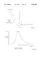
- FIG. 1illustrates the basic alignment problem facing the user of a home satellite receiver.
- An antenna associated with the receiving systemmust be aligned in azimuth so as to receive a signal broadcast by the satellite.
- this alignmentis performed by a user who rotates the antenna in azimuth until receiving an indication that an acceptable signal strength is presented to the receiver system.
- FIG. 2as the antenna is rotated in azimuth, there will come a time at which a peak signal strength for a received signal presented from the antenna to the receiver system is achieved. As the antenna is rotated further in azimuth, the signal strength falls off according to the degree of misalignment.
- a userwill adjust the antenna for the home satellite receiving system so that the antenna points in a direction coincident with the peak signal strength.
- Current home receiver systemsemploy an integral flashing indicator, for example an LED, at the receiving antenna to assist in this alignment.
- the LEDblinks at a frequency proportional to the received signal strength. Accordingly, the user adjusts the alignment of the antenna until the flashing LED indicates proper alignment.
- this alignment aidseldom results in optimal alignment of the antenna because of problems associated with the granularity of resolution achievable by the flashing LED and the inherent inability of a human user to detect slight variations in the frequency of the flashing light source.
- the present inventionprovides an apparatus for aligning an antenna, for example an antenna of home satellite receiver system.
- the apparatusincludes means for detecting a received signal strength of a signal received at the antenna. Coupled to the detecting means are means for generating a display signal indicative of the received signal strength.
- the means for generatingis configured to provide a first display signal when the received signal strength is in first state and to provide a second display signal when the received signal strength is in second state. Coupled to the means for generating the display signal are means for displaying the display signal.
- the means for displayingare capable of responding to both the first display signal and the second display signal.
- the first display signalmay comprise a signal having a frequency proportional to the received signal strength.
- the second display signalmay comprise a signal having a frequency proportional to the inverse of a difference between a maximum received signal strength and a current received signal strength.
- FIG. 1illustrates the alignment of an antenna in azimuth
- FIG. 2illustrates a plot of received signal strength verses antenna position in azimuth
- FIG. 3illustrates a home satellite receiver system employing a signal strength detector and indicator according to one embodiment
- FIG. 4illustrates one embodiment of a signal strength detector and indicator
- FIG. 5illustrates the use of varying display signals according to one embodiment
- FIG. 6is a flow diagram for setting an indicator blink mode and rate according to one embodiment
- FIG. 7is a flow diagram illustrating an indicator blink routine according to one embodiment
- FIG. 8illustrates a home satellite receiver system configured according to the present invention.
- FIG. 9illustrates a preferred method of providing a blink signal to a signal strength indicator.
- a method and apparatus for achieving optimal antenna alignment using a flashing indicatoris described. Although described with reference to certain specific embodiments, those skilled in the art will recognize that the present invention may be practiced without some or all of these details and, further, that other indicators, such as lamps, audio signal generators, visual display devices, or meters may be used instead of an indicator LED.
- the present inventionimproves the manner in which the indicator flashes.
- the indicatoroperates in two modes, which are switched automatically by a system receiver. The first mode illuminates the indicator solidly, extinguishing it periodically at a rate proportional to received signal strength. This mode remembers the highest level measured (i.e., a peak signal strength) and the system remains in this mode during antenna alignment so long as the received signal strength being measured increases or remains constant.
- the second modeis activated when the received signal strength begins decreasing.
- the second modeinverts the appearance of the indicator by changing to a periodic illumination, the frequency of which is proportional to the inverse of the difference between the measured peak signal strength and the current received signal strength.
- the systemoperates in this mode whenever the signal strength is less than the measured peak value.
- the indicatorgraphically reports to a user that the antenna is no longer pointing in a direction corresponding to a peak received signal strength. Additionally, it provides a positive feedback mechanism to the user indicating just how far the antenna is from the optimal alignment position (i.e., the position corresponding to the peak received signal strength) because, when misaligned, the indicator blink rate is a function of pointing error, not just signal strength.
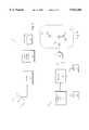
- FIG. 3illustrates a home satellite receiver system 10 which includes an antenna 12 coupled to a receiver 14. Antenna 12 is to be aligned so as to receive a signal broadcast by a satellite. When antenna 12 is aligned in an optimal position, the signal presented to receiver 14 from antenna 12 will have a maximum received signal strength.
- Receiver system 10also incorporates signal strength detector 16 and alignment indicator 18.
- Alignment indicator 18may be any one of a number of indicators, including a flashing LED, an audio tone generator, a visual display (for example a graphical display on a television screen), a signal strength meter, or some other means of providing alignment information to a user.
- Signal strength detector 16is described in more detail below. However, it should be appreciated that signal strength detector 16 may be an integral part of receiver 14.
- indicator 18may be housed on antenna 12 (e.g., on a frame or mounting assembly or on a low noise amplifier), so as to provide an easy point of reference for a user aligning antenna 12.
- FIG. 4illustrates one embodiment of signal strength detector 16 and indicator 18.
- signal strength detector 16includes a processor 20.
- Processor 20may be a separate processor or a processor already used within receiver 14.
- Processor 20receives an indication of received signal strength from receiver 14 via receiver/detector interface unit 22.
- Receiver/detector interface unit 22provides proper electrical signal conditioning to the signal presented to processor 20.
- Processor 20communicates over a bus with ROM 24 and RAM 26.
- ROM 24may store computer readable instructions, such as those described below, for use by processor 20 during the alignment process.
- Processor 20may use RAM 26 to provide temporary storage locations during the alignment process.
- processor 20 as illustrated in FIG. 4may comprise a general purpose programmable microprocessor.
- the functions of processor 20, ROM 24 and/or RAM 26may be combined in a field programmable gate array or complex programmable logic device. Accordingly, the embodiment shown in FIG. 4 is for illustration only.
- processor 20produces an intermediate signal E indicative of antenna alignment errors.
- This intermediate signal Eis presented to NAND gate 28 which drives alignment indicator 18.
- indicator 18includes LED 36.
- resistors 30 and 32are provided in conjunction with transistor 34.
- resistor 30may be 10 k ⁇ while resistor 32 is 220 ⁇ .
- Transistor 34may be a 2N2222 transistor.
- the embodiment shown in FIG. 4will drive LED 36 to approximately the supply voltage Vcc when the signals presented to the input of NAND gate 28 are different. That is, when processor 20 drives the intermediate signal E to logic low value, LED 36 will remain off. However, when processor 20 drives the intermediate signal E to a logic high value, the LED 36 will turn on. By varying the frequency at which the intermediate signal E is produced, processor 20 can control the flashing (or blinking) of LED 36.
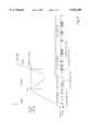
- FIG. 5is a graph depicting the relationship of received signal strength due to antenna positioning error and the corresponding state of the alignment indicator 18.
- the flash rate of alignment indicator 18is a relative measure and is not shown to scale. In all cases, the narrow pulse widths are constant and may be an arbitrary value based upon the maximum flash rate, a desired power consumption, and user viewability of indicator 18.
- indicator 18operates in mode 1.
- mode 1the appearance of indicator 18 is predominately lit (on) and indicator 18 flashes off at a rate proportional to the received signal strength.
- antenna 12is moved in azimuth, a peak signal strength may be found and reported to processor 20.
- antenna 12continues be rotated in azimuth, received signal strength falls off from the peak and signal strength detector 16 and indicator 18 enter mode 2.
- mode 2indicator 18 is predominately off (unlit) and experiences blinking at a rate which is proportional to the pointing error as presented by:
- a usermay pass through various positions in azimuth which correspond to various peaks in received signal strength. These various peaks may correspond to, for example, multi-path transmissions of the broadcast satellite signal. As antenna 12 continues to be rotated in azimuth, one peak (labeled as "New Peak” in FIG. 5) may correspond to a greater received signal strength than all other peaks. This will typically be true for the case where the antenna 12 is optimally aligned to the broadcast satellite signal and is not experiencing multi-path reflections. In practice, the New Peak may be 3-4" wide in azimuth. At this point, signal strength detector 16 remains in mode 1 with a corresponding blink rate of indicator 18. (It will be appreciated that the duration of the New Peak has been exaggerated to show the corresponding steady blink rate of indicator 18.) This alerts the user that antenna 12 is now optimally aligned.
- FIG. 6illustrates an indicator blink mode algorithm 100 for use by signal strength detector 16. It will be appreciated that computer readable instructions corresponding to this algorithm may be stored in ROM 24 for execution by processor 20.
- Indicator blink mode algorithm 100begins at step 102 and, when called, proceeds to step 104 where two variables, Period and Peak, are set to 0.
- processor 20reads various signal strength values presented by receiver/detector interface unit 22. "N" samples (N is an arbitrary integer value greater than 1) are averaged at step 108 to produce an average received signal strength.
- the average received signal strengthis compared with a previously stored peak signal strength. If the average signal strength is less than or equal to the peak signal strength, process 100 proceeds to step 112.
- the variable Periodis set equal to the inverse of the average signal strength.
- the variable Peakis set equal to the average signal strength and a flag Pos -- blink is set true. If, however, at step 110 the average signal strength is determined to be greater than the previous peak signal strength, process 100 proceeds to step 114 where the variable Period is set equal to a value which is the difference between the peak signal strength and the average signal strength and the variable Pos -- blink is set false. When these variables have been set at either step 112 or step 114, process 100 proceeds to step 116 and calls a blink routine.
- FIG. 7illustrates blink routine 200 in greater detail.
- blink routine 200proceeds to step 204 and sets two variables, Accum1 and Accum2 equal to 0.
- step 206blink routine 200 increments variable Accum1.
- Accum1is checked to see whether it is greater than or equal to the variable Period. If so, at step 210 variable Accum2 is loaded with a pulse width value and at step 212 Accum1 is set equal to 0. Otherwise, process 200 proceeds to step 214 where a check is made to see if the state of flag Pos -- blink is true. If not, process 200 proceeds to step 216 where the variable Accum1 is checked to see whether it is less than or equal 1. If not, the indicator, e.g., LED 36, is turned off. Otherwise, at step 220, the indicator is turned on.
- the indicatore.g., LED 36
- step 214If the flag Pos -- blink was true at step 214, a check is made at step 222 to determine if the value of Accum2 is less than or equal to 1. If not, the indicator is turned on at step 224, otherwise the indicator is turned off at step 226.
- step 2208the value at Accum2 is checked to see whether is greater than or equal to 1. If so, Accum2 is decremented at step 230 and process 200 returns to step 206. Otherwise, process 200 loops back to step 206 without decrementing the value of Accum2.
- Periodis the period of the indicator blink rate. Peak is the highest measured signal strength value.
- the boolean flag Pos -- blinkis a state indicator. When set true, the indicator 18 is illuminated, when set false the indicator 18 is extinguished.
- Variable Accum1is a counter for timing a blink period while variable Accum2 is a counter for timing a contrasting flash period. Pulse width indicates the period of the contrasting flash and may be user selectable.
- FIG. 8shows a preferred embodiment of a home satellite television receiver system 300 configured according to the present invention.
- System 300includes antenna 302, receiver 304 and television (TV) 306.
- antenna 302will be positioned outside a home or other residence or building such that it has a clear view of the sky (to intercept signals broadcast by the orbiting satellite(s).
- Antenna 302may be secured in position using mounting assembly 308.
- Mounting assembly 308may be a bracket which is attached to a wall or other supporting structure or may be a pole fixed in the ground or otherwise secured to a relatively stable platform (e.g., a roof).
- Mounting assembly 308is mechanically coupled to antenna 302 and will generally have means for rotably securing antenna 302 so as to permit antenna alignment
- LNAlow noise amplifier
- LNA 310may also be fitted with LED 314 which will provide a visual reference for use during antenna alignment in accordance with the above-described procedures.
- LED 314may be positioned on mounting assembly 308 or antenna 302. The precise positioning of LED 314 is not important so long as it will be visible by a user during the antenna alignment process.
- FIG. 9illustrates aspects of receiver system 300 in greater detail.
- signals from the antenna 302are provided to amplifier circuitry 316 within LNA 310.
- the amplifier circuitry 316amplifies and may also downconvert these signals prior to transmitting the signals to receiver 304 across cable 312.
- Cable 312may be a two conductor coaxial cable as is commonly used in such receiver systems.
- the signals carried by cable 312 from LNA 310 to receiver 304will be video and audio signals to be decoded prior to display on television 306.
- Cable 312may also be used to carry DC power from receiver 304 to LNA 310 to power amplifier circuitry 316. This way, a separate power source is not required for LNA 310.
- Superimposed on the DC power signalmay be a blink signal used to illuminate LED 314.
- the blink signalis provided by receiver 304 to LNA 310 across cable 312 and in accordance with the procedures described above.
- the blink signalincludes pulses of approximately 200 ⁇ sec in duration at a frequency of approximately 50 kHz. Of course, other pulse durations and frequencies may be used depending on the characteristics of the system components.
- the pulsesare repeated at a rate according to the blink mode and blink routines described above. That is, the pulses are repeated at a rate according to antenna alignment errors.
- Capacitor 318provides AC coupling of One Shot 320 to cable 312, allowing the blink signal to pass but preventing the DC power signal from doing so.
- One Shot (i.e., monostable multivibrator) 320produces a pulse of fixed duration in response to the pulses of the blink signal and provides the fixed duration pulses to LED 314.
- LED 314will be activated (i.e., will turn on). The variations in the time between pulses of the blink signal will thus be reflected at LED 314.
- the minimum pulse width for the blink signal pulsesmust be of sufficient duration to activate One Shot 320 while the minimum time between such pulses must be at least equal to the reset time of One Shot 320.
- the alignment indicating systemmay be employed as part of a radio direction finding aid, a microwave antenna alignment system, or other systems requiring accurate antenna alignment. Accordingly, the invention should only be measured in terms of the claims which follows.
Landscapes
- Circuits Of Receivers In General (AREA)
- Variable-Direction Aerials And Aerial Arrays (AREA)
Abstract
Description
The present invention is related to antenna alignment systems and, more particularly, to those systems which rely on signal strength indication to achieve alignment.
With the advent of direct broadcast satellite receiver systems in the home, proper alignment of a receiving antenna for operation of such receivers has become a concern. FIG. 1 illustrates the basic alignment problem facing the user of a home satellite receiver. An antenna associated with the receiving system must be aligned in azimuth so as to receive a signal broadcast by the satellite. Typically, this alignment is performed by a user who rotates the antenna in azimuth until receiving an indication that an acceptable signal strength is presented to the receiver system. As shown in FIG. 2, as the antenna is rotated in azimuth, there will come a time at which a peak signal strength for a received signal presented from the antenna to the receiver system is achieved. As the antenna is rotated further in azimuth, the signal strength falls off according to the degree of misalignment.
Optimally, a user will adjust the antenna for the home satellite receiving system so that the antenna points in a direction coincident with the peak signal strength. Current home receiver systems employ an integral flashing indicator, for example an LED, at the receiving antenna to assist in this alignment. The LED blinks at a frequency proportional to the received signal strength. Accordingly, the user adjusts the alignment of the antenna until the flashing LED indicates proper alignment. However, the use of this alignment aid seldom results in optimal alignment of the antenna because of problems associated with the granularity of resolution achievable by the flashing LED and the inherent inability of a human user to detect slight variations in the frequency of the flashing light source.
Other home satellite receiver system manufacturers have implemented alignment systems which use audible tones, the frequency of which are proportional to the received signal strength. These methods have the same short comings as the flashing LED approach and, in addition, often require that the receiving dish antenna be within audible range of the user's television set (e.g., because the audible tone is broadcast through the television's speakers). In many cases this is impractical, requiring a means for relaying alignment commands between a user positioned at the television set, and therefore within range of the audible tone, and another user positioned at the antenna.
In would be desirable, therefore, to provide an improved means for optimally aligning an antenna for a home satellite receiver system.
In one embodiment, the present invention provides an apparatus for aligning an antenna, for example an antenna of home satellite receiver system. The apparatus includes means for detecting a received signal strength of a signal received at the antenna. Coupled to the detecting means are means for generating a display signal indicative of the received signal strength. The means for generating is configured to provide a first display signal when the received signal strength is in first state and to provide a second display signal when the received signal strength is in second state. Coupled to the means for generating the display signal are means for displaying the display signal. The means for displaying are capable of responding to both the first display signal and the second display signal. The first display signal may comprise a signal having a frequency proportional to the received signal strength. The second display signal may comprise a signal having a frequency proportional to the inverse of a difference between a maximum received signal strength and a current received signal strength.
The present invention is illustrated by way of example, and not limitation, in the figures of the accompanying drawings in which:
FIG. 1 illustrates the alignment of an antenna in azimuth;
FIG. 2 illustrates a plot of received signal strength verses antenna position in azimuth;
FIG. 3 illustrates a home satellite receiver system employing a signal strength detector and indicator according to one embodiment;
FIG. 4 illustrates one embodiment of a signal strength detector and indicator;
FIG. 5 illustrates the use of varying display signals according to one embodiment;
FIG. 6 is a flow diagram for setting an indicator blink mode and rate according to one embodiment;
FIG. 7 is a flow diagram illustrating an indicator blink routine according to one embodiment;
FIG. 8 illustrates a home satellite receiver system configured according to the present invention; and
FIG. 9 illustrates a preferred method of providing a blink signal to a signal strength indicator.
A method and apparatus for achieving optimal antenna alignment using a flashing indicator is described. Although described with reference to certain specific embodiments, those skilled in the art will recognize that the present invention may be practiced without some or all of these details and, further, that other indicators, such as lamps, audio signal generators, visual display devices, or meters may be used instead of an indicator LED. The present invention improves the manner in which the indicator flashes. In particular, the indicator operates in two modes, which are switched automatically by a system receiver. The first mode illuminates the indicator solidly, extinguishing it periodically at a rate proportional to received signal strength. This mode remembers the highest level measured (i.e., a peak signal strength) and the system remains in this mode during antenna alignment so long as the received signal strength being measured increases or remains constant. The second mode is activated when the received signal strength begins decreasing. The second mode inverts the appearance of the indicator by changing to a periodic illumination, the frequency of which is proportional to the inverse of the difference between the measured peak signal strength and the current received signal strength. The system operates in this mode whenever the signal strength is less than the measured peak value. By operating in the second mode, the indicator graphically reports to a user that the antenna is no longer pointing in a direction corresponding to a peak received signal strength. Additionally, it provides a positive feedback mechanism to the user indicating just how far the antenna is from the optimal alignment position (i.e., the position corresponding to the peak received signal strength) because, when misaligned, the indicator blink rate is a function of pointing error, not just signal strength.
FIG. 3 illustrates a homesatellite receiver system 10 which includes anantenna 12 coupled to areceiver 14.Antenna 12 is to be aligned so as to receive a signal broadcast by a satellite. Whenantenna 12 is aligned in an optimal position, the signal presented toreceiver 14 fromantenna 12 will have a maximum received signal strength.
FIG. 4 illustrates one embodiment ofsignal strength detector 16 andindicator 18. For this embodiment,signal strength detector 16 includes aprocessor 20.Processor 20 may be a separate processor or a processor already used withinreceiver 14.Processor 20 receives an indication of received signal strength fromreceiver 14 via receiver/detector interface unit 22. Receiver/detector interface unit 22 provides proper electrical signal conditioning to the signal presented toprocessor 20.Processor 20 communicates over a bus withROM 24 andRAM 26.ROM 24 may store computer readable instructions, such as those described below, for use byprocessor 20 during the alignment process.Processor 20 may useRAM 26 to provide temporary storage locations during the alignment process. It will be appreciated thatprocessor 20 as illustrated in FIG. 4 may comprise a general purpose programmable microprocessor. In other embodiments, the functions ofprocessor 20,ROM 24 and/orRAM 26 may be combined in a field programmable gate array or complex programmable logic device. Accordingly, the embodiment shown in FIG. 4 is for illustration only.
During the alignment process,processor 20 produces an intermediate signal E indicative of antenna alignment errors. This intermediate signal E is presented toNAND gate 28 which drivesalignment indicator 18. For the embodiment illustrated,indicator 18 includesLED 36. In order to properly biasLED 36,resistors transistor 34. For the case where Vcc is 5 volts,resistor 30 may be 10kΩwhile resistor 32 is 220 Ω.Transistor 34 may be a 2N2222 transistor.
The embodiment shown in FIG. 4 will driveLED 36 to approximately the supply voltage Vcc when the signals presented to the input ofNAND gate 28 are different. That is, whenprocessor 20 drives the intermediate signal E to logic low value,LED 36 will remain off. However, whenprocessor 20 drives the intermediate signal E to a logic high value, theLED 36 will turn on. By varying the frequency at which the intermediate signal E is produced,processor 20 can control the flashing (or blinking) ofLED 36.
FIG. 5 is a graph depicting the relationship of received signal strength due to antenna positioning error and the corresponding state of thealignment indicator 18. The flash rate ofalignment indicator 18 is a relative measure and is not shown to scale. In all cases, the narrow pulse widths are constant and may be an arbitrary value based upon the maximum flash rate, a desired power consumption, and user viewability ofindicator 18.
As illustrated in FIG. 5, during times when the received signal strength is increasing,indicator 18 operates inmode 1. Inmode 1, the appearance ofindicator 18 is predominately lit (on) andindicator 18 flashes off at a rate proportional to the received signal strength. Asantenna 12 is moved in azimuth, a peak signal strength may be found and reported toprocessor 20. Asantenna 12 continues be rotated in azimuth, received signal strength falls off from the peak andsignal strength detector 16 andindicator 18enter mode 2. Inmode 2,indicator 18 is predominately off (unlit) and experiences blinking at a rate which is proportional to the pointing error as presented by:
1/(peak signal strength--average measured signal strength)
As shown in FIG. 5, during alignment of antenna 12 a user may pass through various positions in azimuth which correspond to various peaks in received signal strength. These various peaks may correspond to, for example, multi-path transmissions of the broadcast satellite signal. Asantenna 12 continues to be rotated in azimuth, one peak (labeled as "New Peak" in FIG. 5) may correspond to a greater received signal strength than all other peaks. This will typically be true for the case where theantenna 12 is optimally aligned to the broadcast satellite signal and is not experiencing multi-path reflections. In practice, the New Peak may be 3-4" wide in azimuth. At this point, signalstrength detector 16 remains inmode 1 with a corresponding blink rate ofindicator 18. (It will be appreciated that the duration of the New Peak has been exaggerated to show the corresponding steady blink rate ofindicator 18.) This alerts the user thatantenna 12 is now optimally aligned.
FIG. 6 illustrates an indicatorblink mode algorithm 100 for use bysignal strength detector 16. It will be appreciated that computer readable instructions corresponding to this algorithm may be stored inROM 24 for execution byprocessor 20. Indicatorblink mode algorithm 100 begins atstep 102 and, when called, proceeds to step 104 where two variables, Period and Peak, are set to 0. Atstep 106,processor 20 reads various signal strength values presented by receiver/detector interface unit 22. "N" samples (N is an arbitrary integer value greater than 1) are averaged atstep 108 to produce an average received signal strength. Atstep 110, the average received signal strength is compared with a previously stored peak signal strength. If the average signal strength is less than or equal to the peak signal strength,process 100 proceeds to step 112. Atstep 112, the variable Period is set equal to the inverse of the average signal strength. The variable Peak is set equal to the average signal strength and a flag Pos-- blink is set true. If, however, atstep 110 the average signal strength is determined to be greater than the previous peak signal strength,process 100 proceeds to step 114 where the variable Period is set equal to a value which is the difference between the peak signal strength and the average signal strength and the variable Pos-- blink is set false. When these variables have been set at either step 112 or step 114,process 100 proceeds to step 116 and calls a blink routine.
FIG. 7 illustrates blink routine 200 in greater detail. When called atstep 202, blink routine 200 proceeds to step 204 and sets two variables, Accum1 and Accum2 equal to 0. Atstep 206, blink routine 200 increments variable Accum1. Atstep 208 Accum1 is checked to see whether it is greater than or equal to the variable Period. If so, atstep 210 variable Accum2 is loaded with a pulse width value and atstep 212 Accum1 is set equal to 0. Otherwise,process 200 proceeds to step 214 where a check is made to see if the state of flag Pos-- blink is true. If not,process 200 proceeds to step 216 where the variable Accum1 is checked to see whether it is less than or equal 1. If not, the indicator, e.g.,LED 36, is turned off. Otherwise, atstep 220, the indicator is turned on.
If the flag Pos-- blink was true atstep 214, a check is made atstep 222 to determine if the value of Accum2 is less than or equal to 1. If not, the indicator is turned on atstep 224, otherwise the indicator is turned off atstep 226.
Atstep 228, the value at Accum2 is checked to see whether is greater than or equal to 1. If so, Accum2 is decremented atstep 230 andprocess 200 returns to step 206. Otherwise, process 200 loops back to step 206 without decrementing the value of Accum2.
The variables used by the above discussed routines are as follows. Period is the period of the indicator blink rate. Peak is the highest measured signal strength value. The boolean flag Pos-- blink is a state indicator. When set true, theindicator 18 is illuminated, when set false theindicator 18 is extinguished. Variable Accum1 is a counter for timing a blink period while variable Accum2 is a counter for timing a contrasting flash period. Pulse width indicates the period of the contrasting flash and may be user selectable.
FIG. 8 shows a preferred embodiment of a home satellitetelevision receiver system 300 configured according to the present invention.System 300 includesantenna 302,receiver 304 and television (TV) 306. Generally,antenna 302 will be positioned outside a home or other residence or building such that it has a clear view of the sky (to intercept signals broadcast by the orbiting satellite(s).Antenna 302 may be secured in position using mounting assembly 308. Mounting assembly 308 may be a bracket which is attached to a wall or other supporting structure or may be a pole fixed in the ground or otherwise secured to a relatively stable platform (e.g., a roof). Mounting assembly 308 is mechanically coupled toantenna 302 and will generally have means for rotably securingantenna 302 so as to permit antenna alignment
Signals broadcast by one or more satellites are captured byantenna 302 and focused to a feedhorn assembly (not shown). Generally, a low noise amplifier (LNA) 310 will be positioned in close proximity to the feedhorn assembly so as to amplify the relatively weak signals gathered byantenna 302.LNA 310 may also downconvert these signals prior to transmission toreceiver 302 acrosscable 312.
FIG. 9 illustrates aspects ofreceiver system 300 in greater detail. As shown, signals from theantenna 302 are provided toamplifier circuitry 316 withinLNA 310. Theamplifier circuitry 316 amplifies and may also downconvert these signals prior to transmitting the signals toreceiver 304 acrosscable 312.Cable 312 may be a two conductor coaxial cable as is commonly used in such receiver systems. The signals carried bycable 312 fromLNA 310 toreceiver 304 will be video and audio signals to be decoded prior to display ontelevision 306.
Thus, a novel antenna alignment indicator system for a satellite receiver has been disclosed. Although discussed with reference to specific embodiments and the accompanying illustrations, it should be appreciated that the present invention is applicable to a variety of antenna alignment indicator systems. For example, the alignment indicating system may be employed as part of a radio direction finding aid, a microwave antenna alignment system, or other systems requiring accurate antenna alignment. Accordingly, the invention should only be measured in terms of the claims which follows.
Claims (12)
1. An apparatus for aligning an antenna, comprising:
means for detecting a received signal strength of a signal received at said antenna;
means for generating an indication signal indicative of said received signal strength coupled to said means for detecting, said means for generating an indication signal configured to provide a first indication signal having a frequency proportional to said received signal strength and to provide a second indication signal having a frequency proportional to the inverse of a difference between a maximum received signal strength and a current received signal strength; and
means for indicating said indication signal coupled to said means for generating, said means for indicating capable of responding to said first indication signal and said second indication signal.
2. An apparatus as in claim 1 wherein said first indication signal has said frequency proportional to said received signal strength when said received signal strength is greater than or equal to said maximum received signal strength.
3. An apparatus as in claim 2 wherein said second indication signal has said frequency proportional to the inverse of said difference between said maximum received signal strength and said current received signal strength when said received signal strength is less than said maximum received signal strength.
4. An apparatus as in claim 3 wherein said means for indicating comprises a light emitting diode (LED).
5. An apparatus as in claim 4 wherein said means for generating comprises a general purpose programmable device configured to receive a signal indicative of said signal received at said antenna, to derive said signal strength therefrom and to provide one of said first indication signal or said second indication signal in accordance therewith.
6. An apparatus as in claim 5 wherein said general purpose programmable device is a processor coupled to a medium storing computer readable instructions which when executed by said processor cause said processor to derive said signal strength from said signal indicative of said signal received at said antenna and to provide one of said first indication signal or said second indication signal.
7. An apparatus as in claim 3 wherein said means for indicating comprises an audio tone generator.
8. An antenna alignment system comprising:
an antenna configured to receive a signal from a source;
an alignment error detector coupled to said antenna, said alignment error detector configured to produce a variable frequency intermediate signal indicative of an antenna pointing error, said antenna pointing error associated with a relative alignment of said antenna with respect to said signal;
an antenna alignment indicator coupled to receive said intermediate signal and configured to provide an indication of said antenna pointing error in response thereto,
wherein said alignment error detector responds to a signal strength of said signal by determining whether a current signal strength is greater than or equal to a prior maximum signal strength and, if so, producing said intermediate signal so that said intermediate signal has a frequency proportional to said current signal strength, otherwise producing said intermediate signal so that said intermediate signal has a frequency proportional to the inverse of the difference between said maximum signal strength and said current signal strength.
9. An antenna alignment system as in claim 8 wherein said alignment error detector comprises a processor coupled to a storage medium having stored therein computer readable instructions which when executed by said processor cause said processor to respond to said signal strength and generate said intermediate signal in accordance therewith.
10. An antenna alignment system as in claim 8 wherein said antenna alignment indicator comprises a light emitting diode (LED).
11. An antenna alignment system as in claim 9 wherein said antenna alignment indicator comprises an audio signal generator.
12. A method for determining optimal alignment of a receiving antenna, comprising the steps of:
(a) receiving a signal at an antenna and detecting a received signal strength of said signal;
(b) indicating said received signal strength by activating an indication device and periodically deactivating said indication device at a rate proportional to said received signal strength;
(c) adjusting the alignment of said antenna with respect to said signal and repeating step (b) so long as said received signal strength increases or remains constant in magnitude;
(d) detecting a decrease in said magnitude of said received signal strength and modifying said indication of said received signal strength by activating said indication device at a frequency proportional to the inverse of the difference between a maximum received signal strength and a current received signal strength.
Priority Applications (1)
| Application Number | Priority Date | Filing Date | Title |
|---|---|---|---|
| US08/827,034US5923288A (en) | 1997-03-25 | 1997-03-25 | Antenna alignment indicator system for satellite receiver |
Applications Claiming Priority (1)
| Application Number | Priority Date | Filing Date | Title |
|---|---|---|---|
| US08/827,034US5923288A (en) | 1997-03-25 | 1997-03-25 | Antenna alignment indicator system for satellite receiver |
Publications (1)
| Publication Number | Publication Date |
|---|---|
| US5923288Atrue US5923288A (en) | 1999-07-13 |
Family
ID=25248159
Family Applications (1)
| Application Number | Title | Priority Date | Filing Date |
|---|---|---|---|
| US08/827,034Expired - LifetimeUS5923288A (en) | 1997-03-25 | 1997-03-25 | Antenna alignment indicator system for satellite receiver |
Country Status (1)
| Country | Link |
|---|---|
| US (1) | US5923288A (en) |
Cited By (44)
| Publication number | Priority date | Publication date | Assignee | Title |
|---|---|---|---|---|
| US6127936A (en)* | 1998-11-20 | 2000-10-03 | Texas Instruments Isreal Ltd. | Apparatus for and method of providing an indication of the magnitude of a quantity |
| US6229480B1 (en)* | 1999-03-31 | 2001-05-08 | Sony Corporation | System and method for aligning an antenna |
| US6438391B1 (en)* | 1999-10-13 | 2002-08-20 | Harvatek Corp. | Laser diode antenna for mobile phone |
| US20020154055A1 (en)* | 2001-04-18 | 2002-10-24 | Robert Davis | LAN based satellite antenna/satellite multiswitch |
| US6476764B2 (en)* | 2000-09-29 | 2002-11-05 | Hughes Electronics Corporation | Post-installation monitoring method for a satellite terminal antenna |
| US6507325B2 (en) | 2000-12-29 | 2003-01-14 | Bellsouth Intellectual Property Corporation | Antenna alignment configuration |
| US6519450B2 (en)* | 1998-07-28 | 2003-02-11 | Sony Corporation | Radio broadcasting receiver |
| US6683581B2 (en) | 2000-12-29 | 2004-01-27 | Bellsouth Intellectual Property Corporation | Antenna alignment devices |
| US20040060065A1 (en)* | 2002-09-25 | 2004-03-25 | James Thomas H. | Direct broadcast signal distribution methods |
| US6753823B2 (en) | 2000-12-29 | 2004-06-22 | Bellsouth Intellectual Property Corporation | Antenna with integral alignment devices |
| US6789307B1 (en) | 2000-12-29 | 2004-09-14 | Bellsouth Intellectual Property Corporation | Methods for aligning an antenna with a satellite |
| US6816067B2 (en) | 2001-01-29 | 2004-11-09 | Hewlett-Packard Development Company, L.P. | Apparatus and method for selecting wireless devices |
| US6906673B1 (en) | 2000-12-29 | 2005-06-14 | Bellsouth Intellectual Property Corporation | Methods for aligning an antenna with a satellite |
| US6937186B1 (en)* | 2004-06-22 | 2005-08-30 | The Aerospace Corporation | Main beam alignment verification for tracking antennas |
| US6937188B1 (en) | 2001-11-13 | 2005-08-30 | Bellsouth Intellectual Property Corporation | Satellite antenna installation tool |
| US7095378B1 (en) | 2004-01-28 | 2006-08-22 | Fred Paquette | Satellite dish sighting apparatus and alignment system |
| US20060225104A1 (en)* | 2005-04-01 | 2006-10-05 | James Thomas H | Power balancing signal combiner |
| US20060225102A1 (en)* | 2005-04-01 | 2006-10-05 | James Thomas H | Narrow bandwidth signal delivery system |
| US20060225103A1 (en)* | 2005-04-01 | 2006-10-05 | James Thomas H | Intelligent two-way switching network |
| US20060225100A1 (en)* | 2005-04-01 | 2006-10-05 | James Thomas H | System architecture for control and signal distribution on coaxial cable |
| US20060225101A1 (en)* | 2005-04-01 | 2006-10-05 | James Thomas H | Signal injection via power supply |
| US20060225098A1 (en)* | 2005-04-01 | 2006-10-05 | James Thomas H | Transponder tuning and mapping |
| US20060225099A1 (en)* | 2005-04-01 | 2006-10-05 | James Thomas H | Backwards-compatible frequency translation module for satellite video delivery |
| US20060259929A1 (en)* | 2005-04-01 | 2006-11-16 | James Thomas H | Automatic level control for incoming signals of different signal strengths |
| US20070082603A1 (en)* | 2005-10-12 | 2007-04-12 | John Norin | Triple band combining approach to satellite signal distribution |
| US20070089142A1 (en)* | 2005-10-14 | 2007-04-19 | John Norin | Band converter approach to Ka/Ku signal distribution |
| US20070220559A1 (en)* | 2005-09-02 | 2007-09-20 | The Directv Group, Inc. | Frequency translation module discovery and configuration |
| US20070250909A1 (en)* | 2005-09-02 | 2007-10-25 | The Directv Group, Inc. | Network fraud prevention via registration and verification |
| US20080016535A1 (en)* | 2005-09-02 | 2008-01-17 | The Directv Group, Inc. | Frequency shift key control in video delivery systems |
| US20080060021A1 (en)* | 2006-06-16 | 2008-03-06 | Hanno Basse | Digital storage media command and control data indexing |
| EP2073306A1 (en)* | 2007-12-17 | 2009-06-24 | Newtec cy. | Antenna pointing aid device and method |
| ITBO20080692A1 (en)* | 2008-11-13 | 2010-05-14 | Stab S R L | ROTOR FOR PARABOLIC ANTENNA AND PROCEDURE FOR INSTALLING A PARABOLIC ANTENNA. |
| ITBO20080725A1 (en)* | 2008-12-01 | 2010-06-02 | Stab S R L | SIGNAL DETECTOR DEVICE FOR INSTALLING PARABOLIC ANTENNAS. |
| USRE41540E1 (en) | 2000-06-15 | 2010-08-17 | Zenith Electronics LCC | Smart antenna for RF receivers |
| US8019275B2 (en) | 2005-10-12 | 2011-09-13 | The Directv Group, Inc. | Band upconverter approach to KA/KU signal distribution |
| US8229383B2 (en) | 2009-01-06 | 2012-07-24 | The Directv Group, Inc. | Frequency drift estimation for low cost outdoor unit frequency conversions and system diagnostics |
| US8238813B1 (en) | 2007-08-20 | 2012-08-07 | The Directv Group, Inc. | Computationally efficient design for broadcast satellite single wire and/or direct demod interface |
| US20130009819A1 (en)* | 2011-07-08 | 2013-01-10 | Accton Technology Corporation | Outdoor wireless access point and antenna adjusting method thereof |
| US8712318B2 (en) | 2007-05-29 | 2014-04-29 | The Directv Group, Inc. | Integrated multi-sat LNB and frequency translation module |
| US8719875B2 (en) | 2006-11-06 | 2014-05-06 | The Directv Group, Inc. | Satellite television IP bitstream generator receiving unit |
| CN106487440A (en)* | 2016-10-09 | 2017-03-08 | 西安坤蓝电子技术有限公司 | A kind of acquisition methods for judging signal to satelloid |
| US9942618B2 (en) | 2007-10-31 | 2018-04-10 | The Directv Group, Inc. | SMATV headend using IP transport stream input and method for operating the same |
| US10199713B2 (en)* | 2015-05-13 | 2019-02-05 | DISH Technologies L.L.C. | Systems, devices, and methods for orienting an antenna mast |
| US10893264B1 (en) | 2019-06-21 | 2021-01-12 | Voxx International Corporation | Traffic light-type signal strength meter/indicator linked to an antenna AGC circuit |
Citations (4)
| Publication number | Priority date | Publication date | Assignee | Title |
|---|---|---|---|---|
| US4893288A (en)* | 1986-12-03 | 1990-01-09 | Deutsche Thomson-Brandt Gmbh | Audible antenna alignment apparatus |
| US5519405A (en)* | 1993-04-16 | 1996-05-21 | Masprodenkoh Kabushiki Kaisha | Direction adjustment indicator for a satellite radio wave receiving antenna |
| US5561433A (en)* | 1994-06-09 | 1996-10-01 | Thomson Consumer Electronics, Inc. | Apparatus and method for aligning a receiving antenna utilizing an audible tone |
| US5589841A (en)* | 1994-01-18 | 1996-12-31 | Sony Corporation | Satellite antenna with adjustment guidance system |
- 1997
- 1997-03-25USUS08/827,034patent/US5923288A/ennot_activeExpired - Lifetime
Patent Citations (4)
| Publication number | Priority date | Publication date | Assignee | Title |
|---|---|---|---|---|
| US4893288A (en)* | 1986-12-03 | 1990-01-09 | Deutsche Thomson-Brandt Gmbh | Audible antenna alignment apparatus |
| US5519405A (en)* | 1993-04-16 | 1996-05-21 | Masprodenkoh Kabushiki Kaisha | Direction adjustment indicator for a satellite radio wave receiving antenna |
| US5589841A (en)* | 1994-01-18 | 1996-12-31 | Sony Corporation | Satellite antenna with adjustment guidance system |
| US5561433A (en)* | 1994-06-09 | 1996-10-01 | Thomson Consumer Electronics, Inc. | Apparatus and method for aligning a receiving antenna utilizing an audible tone |
Cited By (62)
| Publication number | Priority date | Publication date | Assignee | Title |
|---|---|---|---|---|
| US6519450B2 (en)* | 1998-07-28 | 2003-02-11 | Sony Corporation | Radio broadcasting receiver |
| US6127936A (en)* | 1998-11-20 | 2000-10-03 | Texas Instruments Isreal Ltd. | Apparatus for and method of providing an indication of the magnitude of a quantity |
| US6229480B1 (en)* | 1999-03-31 | 2001-05-08 | Sony Corporation | System and method for aligning an antenna |
| US6438391B1 (en)* | 1999-10-13 | 2002-08-20 | Harvatek Corp. | Laser diode antenna for mobile phone |
| USRE41540E1 (en) | 2000-06-15 | 2010-08-17 | Zenith Electronics LCC | Smart antenna for RF receivers |
| US6476764B2 (en)* | 2000-09-29 | 2002-11-05 | Hughes Electronics Corporation | Post-installation monitoring method for a satellite terminal antenna |
| US7102580B2 (en) | 2000-12-29 | 2006-09-05 | Bellsouth Intellectual Property Corp. | Antenna alignment devices |
| US6889421B1 (en) | 2000-12-29 | 2005-05-10 | Bell South Intellectual Property Corp. | Antenna system installation and tuning method |
| US6683581B2 (en) | 2000-12-29 | 2004-01-27 | Bellsouth Intellectual Property Corporation | Antenna alignment devices |
| US6753823B2 (en) | 2000-12-29 | 2004-06-22 | Bellsouth Intellectual Property Corporation | Antenna with integral alignment devices |
| US6789307B1 (en) | 2000-12-29 | 2004-09-14 | Bellsouth Intellectual Property Corporation | Methods for aligning an antenna with a satellite |
| US6799364B2 (en)* | 2000-12-29 | 2004-10-05 | Bellsouth Intellectual Property Corporation | Antenna aligning methods |
| US6906673B1 (en) | 2000-12-29 | 2005-06-14 | Bellsouth Intellectual Property Corporation | Methods for aligning an antenna with a satellite |
| US6507325B2 (en) | 2000-12-29 | 2003-01-14 | Bellsouth Intellectual Property Corporation | Antenna alignment configuration |
| US6816067B2 (en) | 2001-01-29 | 2004-11-09 | Hewlett-Packard Development Company, L.P. | Apparatus and method for selecting wireless devices |
| US20020154055A1 (en)* | 2001-04-18 | 2002-10-24 | Robert Davis | LAN based satellite antenna/satellite multiswitch |
| US6937188B1 (en) | 2001-11-13 | 2005-08-30 | Bellsouth Intellectual Property Corporation | Satellite antenna installation tool |
| US7954127B2 (en) | 2002-09-25 | 2011-05-31 | The Directv Group, Inc. | Direct broadcast signal distribution methods |
| US20040060065A1 (en)* | 2002-09-25 | 2004-03-25 | James Thomas H. | Direct broadcast signal distribution methods |
| US7095378B1 (en) | 2004-01-28 | 2006-08-22 | Fred Paquette | Satellite dish sighting apparatus and alignment system |
| US6937186B1 (en)* | 2004-06-22 | 2005-08-30 | The Aerospace Corporation | Main beam alignment verification for tracking antennas |
| USRE42472E1 (en)* | 2004-06-22 | 2011-06-21 | The Aerospace Corporation | Main beam alignment verification for tracking antennas |
| US20060225103A1 (en)* | 2005-04-01 | 2006-10-05 | James Thomas H | Intelligent two-way switching network |
| US8024759B2 (en) | 2005-04-01 | 2011-09-20 | The Directv Group, Inc. | Backwards-compatible frequency translation module for satellite video delivery |
| US20060225098A1 (en)* | 2005-04-01 | 2006-10-05 | James Thomas H | Transponder tuning and mapping |
| US20060225099A1 (en)* | 2005-04-01 | 2006-10-05 | James Thomas H | Backwards-compatible frequency translation module for satellite video delivery |
| US20060259929A1 (en)* | 2005-04-01 | 2006-11-16 | James Thomas H | Automatic level control for incoming signals of different signal strengths |
| US8621525B2 (en) | 2005-04-01 | 2013-12-31 | The Directv Group, Inc. | Signal injection via power supply |
| US8549565B2 (en)* | 2005-04-01 | 2013-10-01 | The Directv Group, Inc. | Power balancing signal combiner |
| US20060225101A1 (en)* | 2005-04-01 | 2006-10-05 | James Thomas H | Signal injection via power supply |
| US20060225100A1 (en)* | 2005-04-01 | 2006-10-05 | James Thomas H | System architecture for control and signal distribution on coaxial cable |
| US7987486B2 (en) | 2005-04-01 | 2011-07-26 | The Directv Group, Inc. | System architecture for control and signal distribution on coaxial cable |
| US20060225102A1 (en)* | 2005-04-01 | 2006-10-05 | James Thomas H | Narrow bandwidth signal delivery system |
| US7958531B2 (en) | 2005-04-01 | 2011-06-07 | The Directv Group, Inc. | Automatic level control for incoming signals of different signal strengths |
| US20060225104A1 (en)* | 2005-04-01 | 2006-10-05 | James Thomas H | Power balancing signal combiner |
| US7950038B2 (en) | 2005-04-01 | 2011-05-24 | The Directv Group, Inc. | Transponder tuning and mapping |
| US7945932B2 (en) | 2005-04-01 | 2011-05-17 | The Directv Group, Inc. | Narrow bandwidth signal delivery system |
| US7900230B2 (en) | 2005-04-01 | 2011-03-01 | The Directv Group, Inc. | Intelligent two-way switching network |
| US20070250909A1 (en)* | 2005-09-02 | 2007-10-25 | The Directv Group, Inc. | Network fraud prevention via registration and verification |
| US8789115B2 (en) | 2005-09-02 | 2014-07-22 | The Directv Group, Inc. | Frequency translation module discovery and configuration |
| US7937732B2 (en) | 2005-09-02 | 2011-05-03 | The Directv Group, Inc. | Network fraud prevention via registration and verification |
| US20080016535A1 (en)* | 2005-09-02 | 2008-01-17 | The Directv Group, Inc. | Frequency shift key control in video delivery systems |
| US20070220559A1 (en)* | 2005-09-02 | 2007-09-20 | The Directv Group, Inc. | Frequency translation module discovery and configuration |
| US20070082603A1 (en)* | 2005-10-12 | 2007-04-12 | John Norin | Triple band combining approach to satellite signal distribution |
| US7991348B2 (en) | 2005-10-12 | 2011-08-02 | The Directv Group, Inc. | Triple band combining approach to satellite signal distribution |
| US8019275B2 (en) | 2005-10-12 | 2011-09-13 | The Directv Group, Inc. | Band upconverter approach to KA/KU signal distribution |
| US20070089142A1 (en)* | 2005-10-14 | 2007-04-19 | John Norin | Band converter approach to Ka/Ku signal distribution |
| US20080060021A1 (en)* | 2006-06-16 | 2008-03-06 | Hanno Basse | Digital storage media command and control data indexing |
| US8719875B2 (en) | 2006-11-06 | 2014-05-06 | The Directv Group, Inc. | Satellite television IP bitstream generator receiving unit |
| US8712318B2 (en) | 2007-05-29 | 2014-04-29 | The Directv Group, Inc. | Integrated multi-sat LNB and frequency translation module |
| US8238813B1 (en) | 2007-08-20 | 2012-08-07 | The Directv Group, Inc. | Computationally efficient design for broadcast satellite single wire and/or direct demod interface |
| US9942618B2 (en) | 2007-10-31 | 2018-04-10 | The Directv Group, Inc. | SMATV headend using IP transport stream input and method for operating the same |
| EP2073306A1 (en)* | 2007-12-17 | 2009-06-24 | Newtec cy. | Antenna pointing aid device and method |
| ITBO20080692A1 (en)* | 2008-11-13 | 2010-05-14 | Stab S R L | ROTOR FOR PARABOLIC ANTENNA AND PROCEDURE FOR INSTALLING A PARABOLIC ANTENNA. |
| ITBO20080725A1 (en)* | 2008-12-01 | 2010-06-02 | Stab S R L | SIGNAL DETECTOR DEVICE FOR INSTALLING PARABOLIC ANTENNAS. |
| US8229383B2 (en) | 2009-01-06 | 2012-07-24 | The Directv Group, Inc. | Frequency drift estimation for low cost outdoor unit frequency conversions and system diagnostics |
| US9653776B2 (en)* | 2011-07-08 | 2017-05-16 | Accton Technology Corporation | Outdoor wireless access point and antenna adjusting method thereof |
| US20130009819A1 (en)* | 2011-07-08 | 2013-01-10 | Accton Technology Corporation | Outdoor wireless access point and antenna adjusting method thereof |
| US10199713B2 (en)* | 2015-05-13 | 2019-02-05 | DISH Technologies L.L.C. | Systems, devices, and methods for orienting an antenna mast |
| CN106487440A (en)* | 2016-10-09 | 2017-03-08 | 西安坤蓝电子技术有限公司 | A kind of acquisition methods for judging signal to satelloid |
| CN106487440B (en)* | 2016-10-09 | 2019-05-10 | 西安坤蓝电子技术有限公司 | A kind of acquisition method of judging signal aiming at satellite |
| US10893264B1 (en) | 2019-06-21 | 2021-01-12 | Voxx International Corporation | Traffic light-type signal strength meter/indicator linked to an antenna AGC circuit |
Similar Documents
| Publication | Publication Date | Title |
|---|---|---|
| US5923288A (en) | Antenna alignment indicator system for satellite receiver | |
| US5640697A (en) | Wideband multiple conversion receiver system with means for avoiding receiver spurs by combined switching of multiple local oscillator frequencies | |
| US5146226A (en) | Motor vehicle police radar detector for detecting multiple radar sources | |
| US5206651A (en) | Motor vehicle police radar detector for detecting multiple radar sources | |
| US5250951A (en) | Motor vehicle police radar detector for detecting multiple radar sources | |
| EP0132382B1 (en) | Direct satellite broadcast receiving system | |
| US5493310A (en) | Satellite antenna with adjustment guidance system | |
| US6104341A (en) | Satellite receiving system featuring antenna reception level signal generation in response to signal reception level and/or bit error rate | |
| US5164729A (en) | Police radar warning receiver with auto-mute function | |
| US6313799B1 (en) | Diagnostic device for a multi-antenna arrangement | |
| US6070062A (en) | Mobile radio wave receiver with adaptive automatic gain control | |
| US3821651A (en) | Scanning control circuit for use in signal seeking radio receiver | |
| JPH05291978A (en) | Power saving type microwave detector | |
| US5173701A (en) | Radar apparatus with jamming indicator and receiver device with jamming indicator | |
| EP0935308B1 (en) | Direction adjustment indicator for a satellite radio wave receiving antenna | |
| JP2693468B2 (en) | Radar performance monitoring device | |
| US6693578B1 (en) | Mixer optimization for active radar warning receiver | |
| EP0247370A2 (en) | Method and apparatus for loop direction finding with no ambiguity | |
| US4190803A (en) | Multifrequency superheterodyne receiver with priority channel monitoring | |
| US4337486A (en) | Synchronizing signal discriminator for use in channel selection apparatus of television receiver | |
| US8233640B2 (en) | Sound output device | |
| US6590377B2 (en) | Narrow band frequency detection circuit | |
| JPS62194480A (en) | Apparatus for monitoring performance of radar | |
| JP2002217763A (en) | Input level display method, input level display device | |
| KR930005908B1 (en) | Visual automatic adjustment circuit |
Legal Events
| Date | Code | Title | Description |
|---|---|---|---|
| AS | Assignment | Owner name:SONY CORPORATION, JAPAN Free format text:ASSIGNMENT OF ASSIGNORS INTEREST;ASSIGNOR:PEDLOW JR., LEO MARK;REEL/FRAME:008490/0872 Effective date:19970318 Owner name:SONY ELECTRONICS, INC., NEW JERSEY Free format text:ASSIGNMENT OF ASSIGNORS INTEREST;ASSIGNOR:PEDLOW JR., LEO MARK;REEL/FRAME:008490/0872 Effective date:19970318 | |
| STCF | Information on status: patent grant | Free format text:PATENTED CASE | |
| FPAY | Fee payment | Year of fee payment:4 | |
| FPAY | Fee payment | Year of fee payment:8 | |
| FPAY | Fee payment | Year of fee payment:12 | |
| AS | Assignment | Owner name:SONY CORPORATION, JAPAN Free format text:ASSIGNMENT OF ASSIGNORS INTEREST;ASSIGNOR:SONY ELECTRONICS INC.;REEL/FRAME:036330/0420 Effective date:20150731 |