US5923254A - Programmable animal collar - Google Patents
Programmable animal collarDownload PDFInfo
- Publication number
- US5923254A US5923254AUS09/014,948US1494898AUS5923254AUS 5923254 AUS5923254 AUS 5923254AUS 1494898 AUS1494898 AUS 1494898AUS 5923254 AUS5923254 AUS 5923254A
- Authority
- US
- United States
- Prior art keywords
- transmitter
- tracking device
- collar
- microcontroller
- flexible antenna
- Prior art date
- Legal status (The legal status is an assumption and is not a legal conclusion. Google has not performed a legal analysis and makes no representation as to the accuracy of the status listed.)
- Expired - Lifetime
Links
Images


Classifications
- G—PHYSICS
- G08—SIGNALLING
- G08B—SIGNALLING OR CALLING SYSTEMS; ORDER TELEGRAPHS; ALARM SYSTEMS
- G08B21/00—Alarms responsive to a single specified undesired or abnormal condition and not otherwise provided for
- G08B21/02—Alarms for ensuring the safety of persons
- G08B21/0202—Child monitoring systems using a transmitter-receiver system carried by the parent and the child
- G08B21/0288—Attachment of child unit to child/article
- A—HUMAN NECESSITIES
- A01—AGRICULTURE; FORESTRY; ANIMAL HUSBANDRY; HUNTING; TRAPPING; FISHING
- A01K—ANIMAL HUSBANDRY; AVICULTURE; APICULTURE; PISCICULTURE; FISHING; REARING OR BREEDING ANIMALS, NOT OTHERWISE PROVIDED FOR; NEW BREEDS OF ANIMALS
- A01K15/00—Devices for taming animals, e.g. nose-rings or hobbles; Devices for overturning animals in general; Training or exercising equipment; Covering boxes
- A01K15/02—Training or exercising equipment, e.g. mazes or labyrinths for animals ; Electric shock devices; Toys specially adapted for animals
- A01K15/021—Electronic training devices specially adapted for dogs or cats
- A—HUMAN NECESSITIES
- A01—AGRICULTURE; FORESTRY; ANIMAL HUSBANDRY; HUNTING; TRAPPING; FISHING
- A01K—ANIMAL HUSBANDRY; AVICULTURE; APICULTURE; PISCICULTURE; FISHING; REARING OR BREEDING ANIMALS, NOT OTHERWISE PROVIDED FOR; NEW BREEDS OF ANIMALS
- A01K27/00—Leads or collars, e.g. for dogs
- A01K27/009—Leads or collars, e.g. for dogs with electric-shock, sound, magnetic- or radio-waves emitting devices
Definitions
- the present inventionrelates to animal collars. More particularly, the present invention relates to animal collars which are equipped with radio transmitters that are used for locating or tracking purposes.
- the present inventionis directed to a programmable animal collar which allows for field selection of transmission frequencies or channels.
- the present inventionprovides a tracking device which includes:
- a transmittermounted to the collar in a transmitter housing
- the transmittercomprises a multichannel transmitter which includes a magnetically operable circuit which allows external programmability of transmission channel selection.
- the present inventionalso provides a tracking device which includes:
- a transmittermounted to the collar in a transmitter housing
- the transmittercomprises a programmably channelized multichannel transmitter.
- the present inventionfurther provides a method of externally programming a multichannel transmitter which involves:
- FIG. 1is a front view of an animal collar that is equipped with a radio transmitter according to the present invention.
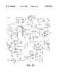
- FIG. 2is a circuit diagram for a programmable transmitter according to one embodiment of the present invention.
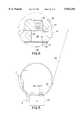
- FIG. 3ais a top view of a PC board layout for the circuit of FIG. 2.
- FIG. 3bis a bottom view of the PC board of FIG. 3a.
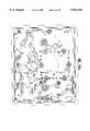
- FIG. 4is a circuit diagram for a programmable transmitter according to another embodiment of the present invention.
- FIG. 5is a front view of an animal collar that is equipped with a radio transmitter according to another embodiment of the present invention.
- FIG. 6is an enlarged cross-sectional view of the connection between the electrical transmitter case, antenna element and collar.
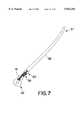
- FIG. 7is a side view of another embodiment of an antenna element.
- the present inventionis directed to animal collars which include programmable transmitters.
- the transmittersare particularly designed to be field programmable.
- the transmittersare programmably channelized multichannel transmitters.
- the transmitters of the present inventionare designed in such a manner that the user can select between a multiplicity of frequencies or channels and program the transmitter by non-mechanical means in a field environment so that the transmitter transmits over a selected frequency or channel.
- non-mechanicalis intended to contrast the present invention from the use of "mechanical” means such as mechanical switches, jumpers, and the like. Such mechanical means may be used. However, their use would require that they be surface mounted or located under an access plate or cover which would have to be removed to make necessary setting changes.
- the transmittersare externally field tuned to any one of a number of frequencies or channels externally. This allows for the use of a sealed unit and avoids the use of exposed mechanical switches or the need for tools to open access plates or covers.
- a sealed unit, or one that otherwise has provisions for a replaceable battery,is more suitable for use in rough field conditions which may include inclement weather.
- the animal collars of the present inventionare generally described herein as being useful for tracking and locating dogs, e.g. hunting dogs. Nevertheless, it is to be understood that the animal collars of the present invention are not to be considered as limited for use on hunting dogs or dogs in general. In this regard, the animal collars of the present invention could be used to track any type of domestic or non-domestic animal. Moreover, it is to be understood that the programmable transmitters of the present invention could be used separately from collars, or could otherwise be mounted on other support means.
- the transmitters of the present inventioncould be mounted to belts, leg bands, arm bands, wrist bands, backpack shoulder straps, horse saddles or carried separately and used to locate lost hikers, backpackers, horseback riders, cavers, miners, mentally deficient persons, and the like.
- the programmable transmitterscould be used to tag a base such as a campsite, a pier or dock, a parked vehicle, etc. so that such a base could be found with a directional locating receiver. It is also possible to utilize the present invention in conjunction with a transponder rather than a transmitter.
- FIG. 1is a front view of an animal collar that is equipped with a radio transmitter according to the present invention.
- the animal collarincludes a strap or web 1 which can be made from a suitable material such as nylon or leather.
- a conventional buckle 2is attached to one end of the strap or web 1.
- the buckle 2receives a free end 3 of the strap or web 1 and secures the free end 3 at adjustable increments in a known manner.
- the transmitter 4is mounted on a lower portion of the collar along strap or web 1.
- the transmitter 4can be secured to strap or web 1 according to any convenient manner.
- transmitter 4can be secured to strap or web 1 by mechanical fasteners 5, e.g. screws, bolts, rivets, etc. which pass through strap or web 1 and clamping plate 6 from (or into) the housing of transmitter 4.
- a flexible antenna 7extends out of the transmitter 4 and is directed upward by guide member 8 which is attached to a side portion of the strap or web 1.
- the antennamay be coupled to the transmitter by a wiring system and have a separate base which is attached to the strap or web.
- the collar of FIG. 1is used for tracking and locating an animal.
- Further embodiments of a collar according to the present inventionmay include receivers, transponders and/or other electronic elements which are attached to the collar.
- the collarmay be provided with an audible or visual locating device such as a sonic means or illumination means which can be activated remotely.
- the collarmay be provided with a stimulation means such as a pair of electrodes which can be activated to administer a corrective signal as needed for training.
- FIG. 2is a circuit diagram of a programmable transmitter according to one embodiment of the present invention. Unless otherwise specified, the resistance values in FIG. 2 and throughout this disclosure are given in ohms, the capacitance values are given in microfarads, and the induction values are given in micro henries.
- Battery 10powers the entire transmitter circuit which is controlled by microcontroller 11. As discussed in detail below, microcontroller 11 is field programmed via magnetic switch 12. Once field programmed, microcontroller 11 programs phase locked loop (PLL) synthesizer chip 13 which controls the voltage controlled oscillator (VCO) circuit 14, in such a manner to maintain a desired transmission output frequency. The output from the VCO circuit 14 is amplified by final amplifier 15 and transmitted by antenna 16.
- PLLphase locked loop
- microcontroller 11One of the functions of microcontroller 11 is to monitor low battery conditions. This function is performed by voltage detector 17 which provides a signal to microcontroller 11 when the voltage output from battery 10 falls below a threshold level. Upon detection of a low battery condition, microcontroller 11 controls light emitting diode (LED) 18 to display a "low battery” alert. For example, LED 18 may be changed from displaying a normal "on" operating color (e.g. green) to another color (e.g. flashing red). Alternatively, separate LED's may be used to display normal operation conditions and a "low battery” condition.
- LED 18may be changed from displaying a normal "on" operating color (e.g. green) to another color (e.g. flashing red).
- separate LED'smay be used to display normal operation conditions and a "low battery” condition.
- the transmitter circuitis activated/deactivated, i.e. turned “on”/"off", by use of magnetic reed switch 12.
- Magnetic reed switch 12is positioned within the housing of transmitter 4 (see FIG. 1) at a location which allows convenient placement of a magnet adjacent the magnetic reed switch 12 outside the transmitter housing. Once a magnet is held against the outside of the transmitter housing in the vicinity of magnetic reed switch 12, power from battery 10 activates or "wakes up" microcontroller 11. If a magnet is held against the outside of the transmitter in the vicinity of magnetic reed switch during initial activation, microcontroller 11 will automatically go into a program mode. In the circuit diagram of FIG. 2, LED 18 will flash an amber color to indicate that microcontroller 11 is in its program mode. LED 18 will continue flashing an amber color at a rate, e.g. one flash per second, which represents an increasing channel count. That is, during the program mode, each succeeding flash of LED 18 corresponds to an incrementally increasing channel count made by the microcontrol
- Microcontroller 11is externally programmed by holding a magnet against the outside of the transmitter in the vicinity of magnetic reed switch 12 and counting the number of flashes of LED 18. Since each flash corresponds to an incrementally increasing channel count, one need only count the number of flashes to select a desired channel. Upon removal of the external magnet after channel selection, the microcontroller 11 programs the PLL synthesizer chip 13 to operate the VCO circuit 14 so as to produce a signal that effects transmission over the last counted channel frequency. The number of channels and the frequency represented by each channel are factory programmed into the memory of the microcontroller. Once the microcontroller 11 is externally programmed, it programs the PLL synthesizer chip 13 with the necessary data so that the transmitter transmits over a selected channel.
- magnetic means other than the magnetic reed switch 12can be used to externally program the transmission channel selection.
- meanssuch as Hall effect devices, GMR (Giant Magneto Resistance) devices, AMR (Anisotropic Magneto Resistance) devices, and similar devices could be used.
- the PLL synthesizer chip 13echoes back the channel count using LED 18 to display a number of flashes that are equal to the programmed channel count. During this verification, LED 18 can flash a color which is different from amber, e.g. green. If a wrong channel has been programmed or the user wishes to change the channel selection, he or she merely deactivates and then reactivates the transmitter circuit in order to reinitiate programming (channel selection) of microcontroller 11.
- the transmitteris deactivated or turned off by holding the magnet against the outside of the transmitter in the vicinity of magnetic reed switch 12 until the LED 18 displays a color (e.g. red) which indicates that the voltage to PLL synthesizer chip 13, and VCO circuit 14 have been turned off. At the same time the ground return for the oscillator is switched to open by transistor 19 and the base bias for the final amplifier 15 is also turned off.
- a colore.g. red
- microcontroller 11turns on the VCO circuit 14 and final amplifier 15 by pulsing pin 11, thereby turning the transmitter ON/OFF at a preprogrammed duty cycle.
- the RF energyis delivered to external antenna 16 for purposes of radiation.
- the circuit shown in FIG. 2is designed to operate using a replaceable 3 volt lithium battery.
- the voltage from battery 10is stepped up by voltage converter 20 which provides a constant 5 volt DC voltage to the PLL synthesizer chip 13 and the VCO circuit 14, thus ensuring consistent performance as battery 10 drains.
- Jumpers for the microcontrollerare used to determine what frequency band the transmitter will operate in (216, 217, 218, 219 or 220 MHZ). These jumpers are set at the factory. The transmitter may operate at given frequencies in each of these bands by using different software in the microcontroller, allowing for the unique factory customization of transmitter frequencies for the end user.
- FIG. 3ais a top view of a PC board layout for the circuit of FIG. 2.
- FIG. 3bis a bottom view of the PC board of FIG. 3a.
- LED 18provides three different colors for indicating various states of operation of the transmitter. This can be accomplished by using a tricolor LED 18 as depicted in FIG. 2. Alternatively, separate LED's can be used or other low energy display means, including liquid display crystals, optical fibers, etc.
- a piezoelectric speaker 21can be provided. In operation, microcontroller 11 controls piezoelectric speaker 21 so that it enunciates a series of beeps in synchronization with the flashes from LED 18 during channel selection and verification. This provides the user with both an audible and visual display of channel programming.
- FIG. 4is a circuit diagram for a programmable transmitter according to another embodiment of the present invention. To the extent that the circuit diagram of FIG. 4 is similar to that of FIG. 2, common reference numbers have been used to identify common components.
- Battery 10powers the entire transmitter circuit which is controlled by microcontroller 11. As discussed in detail below, microcontroller 11 is field programmed via magnetic switch 12. Once field programmed, microcontroller 11 programs phase locked loop (PLL) synthesizer chip 13 which controls the voltage controlled oscillator (VCO) circuit 14, in such a manner to maintain a desired transmission output frequency. The output from the VCO circuit 14 is amplified by final amplifier 15 and transmitted by antenna 16.
- PLLphase locked loop
- microcontroller 11One of the functions of microcontroller is to monitor low battery conditions. This function is performed by voltage detector 17 which provides a signal to microcontroller 11 when the voltage output from battery 10 falls below a threshold level. Upon detection of a low battery condition, microcontroller 11 controls light emitting diode (LED) 18 to display a "low battery” alert. For example, LED 18 may be changed from displaying a normal "on" operating color (e.g. green) to another color (e.g. flashing red). Alternatively, separate LED's may be used to display normal operation conditions and a "low battery” condition.
- LED 18may be changed from displaying a normal "on" operating color (e.g. green) to another color (e.g. flashing red).
- separate LED'smay be used to display normal operation conditions and a "low battery” condition.
- the transmitter circuitis activated/deactivated, i.e. turned “on”/"off", by use of magnetic reed switch 12.
- Magnetic reed switch 12is positioned within the housing of transmitter 4 (see FIGS. 1 or 5) at a location which allows convenient placement of a magnet adjacent the magnetic reed switch 12 outside the transmitter housing. Once a magnet is held against the outside of the transmitter housing in the vicinity of magnetic reed switch 12, power from battery 10 activates or "wakes up" microcontroller 11. If a magnet is held against the outside of the transmitter in the vicinity of magnetic reed switch during initial activation for a longer period of time, microcontroller 11 will automatically go into a program mode. In the circuit diagram of FIG.
- LED 18will flash an amber color to indicate that microcontroller 11 is in its program mode. LED 18 will continue flashing an amber color at a rate, e.g. one flash per second, which represents an increasing channel count. That is, during the program mode, each succeeding flash of LED 18 corresponds to an incrementally increasing channel count made by the microcontroller 11.
- Microcontroller 11is externally programmed by holding a magnet against the outside of the transmitter in the vicinity of magnetic reed switch 12 and counting the number of flashes of LED 18. Since each flash corresponds to an incrementally increasing channel count, one need only count the number of flashes to select a desired channel. Upon removal of the external magnet after channel selection, the microcontroller 11 programs the PLL synthesizer chip 13 to operate the VCO circuit 14 so as to produce a signal that effects transmission over the last counted channel frequency. The number of channels and the frequency represented by each channel are factory programmed into the memory of the microcontroller. Once the microcontroller 11 is externally programmed, it programs the PLL synthesizer chip 13 with the necessary data so that the transmitter transmits over a selected channel.
- magnetic means other than the magnetic reed switch 12can be used to externally program the transmission channel selection.
- meanssuch as Hall effect devices, GMR (Giant Magneto Resistance) devices, AMR (Anisotropic Magneto Resistance) devices, and similar devices could be used.
- the microcontroller chip 11echoes back the channel count using LED 18 to display a number of flashes that are equal to the programmed channel count. During this verification, LED 18 can flash a color which is different from amber, e.g. green. If a wrong channel has been programmed or the user wishes to change the channel selection, he or she merely deactivates and then reactivates the transmitter circuit in order to reinitiate programming (channel selection) of microcontroller 11.
- the transmitteris deactivated or turned off by holding the magnet against the outside of the transmitter in the vicinity of magnetic reed switch 12 until the LED 18 displays a color (e.g. red) which indicates that the voltage to PLL synthesizer chip 13, and VCO circuit 14 have been turned off.
- a colore.g. red
- Buffer circuit 9buffers the load to transistor Q2 of VCO circuit 14.
- microcontroller 11turns on the VCO circuit 14 and final amplifier 15 by pulsing pins 11 and 12, thereby turning the transmitter ON/OFF at a preprogrammed duty cycle.
- the RF energyis delivered to external antenna 16 for purposes of radiation.
- the circuit shown in FIG. 4is designed to operate using a replaceable 3 volt lithium battery.
- the voltage from battery 10is stepped up by voltage converter 20 which provides a constant 5 volt DC voltage to the PLL synthesizer chip 13 and the VCO circuit 14, thus ensuring consistent performance as battery 10 drains.
- Voltage regulator 24regulates the voltage to a digital portion of PLL synthesizer chip 13 so that the digital portion will run at the same logic levels as microcontroller 11.
- Jumpers for the microcontrollerare used to determine what frequency band the transmitter will operate in (216, 217, 218, 219 or 220 MHZ). These jumpers are set at the factory. The transmitter may operate at given frequencies in each of these bands by using different software in the microcontroller, allowing for the unique factory customization of transmitter frequencies for the end user.
- LED 18provides three different colors for indicating various states of operation of the transmitter. This can be accomplished by using a tricolor LED 18 as depicted in FIG. 4. Alternatively, separate LED's can be used or other low energy display means, including liquid display crystals, optical fibers, etc.
- Tilt switch 22may be included and used to effect a change in the transmitted signal which change indicates a change in the orientation of the transmitter. For example, the tilt switch 22 can be used to effect a change in the transmitted signal when a dog wearing the transmitter has treed an animal.
- FIG. 5is a front view of an animal collar that is equipped with a radio transmitter according to another embodiment of the present invention.
- the animal collar of FIG. 5is similar to the animal collar of FIG. 1, with regard to the strap or web 1, having free end 3 and buckle 2.
- the animal collar of FIG. 5includes a different flexible antenna element 25 which is mounted to the strap of web 1 rather than to the transmitter as depicted in FIG. 1.
- the flexible antenna element 25comprises a elongated metal blade member which has a curved cross-sectional shape.
- the flexible antenna element 25can be made from any suitable metal such as spring steel or shape-memory materials which allow the antenna element to return to its original shape after being bent or folded. Examples of materials which are not limited to the exclusive use of metals include metal laminate plastics, metal impregnated plastics, metal coated plastics, metal plated plastics, etc.
- the flexible antenna element 25is coupled to the transmitter case 26 in the manner discussed below, and extends from the transmitter case 26 in a sleeve 27 which surrounds an adjacent portion of the strap or web 1 and keeps the flexible antenna element 25 in close proximity to the strap or web 1 of the collar along an initial length of the flexible antenna element 25.
- the sleeve 27helps ensure that the free end of the flexible antenna element 25 is directed upward when the device is worn by an animal so that a signal can be properly transmitted therefrom.
- the sleeve 27itself should be flexible and reasonably tight so that the portion of the flexible antenna element 25 within sleeve 27 is snug against the strap or web 1.
- the sleeve 27can comprise a heat-shrinkable material which can be shrunk after the antenna element 25 and strap or web 1 are positioned therein.
- the sleeve 27can comprise an elastomeric or polymeric material or a metallic spring or a spring made of a shape memory material into which the antenna element 25 and strap or web 1 are inserted.
- the sleeve 27can be a continuous structure, or a discrete structure such as a spring, mesh or woven structure. Otherwise, the sleeve 27 can be replaced with one or more mechanical fasteners attached to strap or web 1.
- the sleeve 27is merely attached to the strap or web 1 and only surrounds the antenna element 25.
- the sleeve 27In addition to directing the free end of the antenna element 25 upward, the sleeve 27 also absorbs mechanical shocks which occur when the antenna element 25 contacts or impacts objects such as brush, vegetation and other objects or obstacles. By absorbing the mechanical shocks along the portion of the antenna element 25 that is contained within the sleeve 27, the mechanical shocks are not concentrated at a single point along the antenna 25 which might be susceptible to mechanical failure.
- FIG. 6is an enlarged cross-sectional view of the connection between the electrical transmitter case, antenna element and collar.
- the antenna element 25includes at least one through-hole through which a threaded stud 28 attached to transmitter 4 can be inserted and used to couple antenna element 25 to the transmitter 4.
- the threaded stud 28is attached at one end to a circuit board (not shown) in a known manner or to a portion of the transmitter housing. As depicted, the threaded stud 28 extends though the transmitter housing lid 29, then through through-hole in the antenna element 25. Next, a washer 31, which can be a curved spring washer is placed over the antenna element 25.
- the threaded stud 28is inserted through a hole in strap or web 1 and through a cover or backing plate 32.
- the assemblyis secured by a threaded standoff nut 33 having a flange 34.
- the wider portion 35 of the standoff nut 33clamps against the washer 31 and the flange 34 clamps against the cover or backing plate 32 as depicted.
- the end of the threaded stud which extends from the cover or backing plate 32is covered by a threaded stud cap 36 which prevents the otherwise exposed end of the threaded stud 28 from irritating an animal's neck.
- FIG. 7is a side view of another embodiment of an antenna element.
- the antenna element of FIG. 7includes a wirewound cable section 37 which is similar in configuration to a speedometer cable.
- the wirewound cable section 37is covered by a protective, weather resistant coating 38 such as a plastic or elastomeric material.
- a protective, weather resistant coating 38such as a plastic or elastomeric material.
- One end of the wirewound cable section 37has a portion of the protective coating 38 removed to expose the underlying wirewound cable 37.
- a small section of wire mesh 39is slid over the exposed portion of the wirewound cable 37 and secured thereto by a clamp 40.
- the other end of the wire mesh 39is secured by a clamp 41 to an eyelet 42.
- FIG. 7depicts one manner by which wirewound cable section 37 can be coupled to an eyelet 42.
- the eyelet 42is in turn used to couple the antenna element 25 to the electrical transmitter as discussed above. That is, the hole in eyelet 42 is used in place of the through-hole in the end of the antenna element 25 of FIGS. 5 and 6.
- there are other means to couple the wirewound cable section 37 to the eyelet 42for example, one or more flexible wires, a conductive spring, a flat wire mesh, etc. could be used in place of a cylindrical portion of wire mesh.
- the clamps 40 and 41could be replaced by a soldered or welded connection.
Landscapes
- Life Sciences & Earth Sciences (AREA)
- Environmental Sciences (AREA)
- Health & Medical Sciences (AREA)
- General Health & Medical Sciences (AREA)
- Biodiversity & Conservation Biology (AREA)
- Animal Husbandry (AREA)
- General Physics & Mathematics (AREA)
- Physical Education & Sports Medicine (AREA)
- Physics & Mathematics (AREA)
- Animal Behavior & Ethology (AREA)
- Zoology (AREA)
- Emergency Management (AREA)
- Business, Economics & Management (AREA)
- Child & Adolescent Psychology (AREA)
- Transmitters (AREA)
Abstract
Description
Claims (19)
Priority Applications (1)
| Application Number | Priority Date | Filing Date | Title |
|---|---|---|---|
| US09/014,948US5923254A (en) | 1997-01-29 | 1998-01-28 | Programmable animal collar |
Applications Claiming Priority (2)
| Application Number | Priority Date | Filing Date | Title |
|---|---|---|---|
| US3652297P | 1997-01-29 | 1997-01-29 | |
| US09/014,948US5923254A (en) | 1997-01-29 | 1998-01-28 | Programmable animal collar |
Publications (1)
| Publication Number | Publication Date |
|---|---|
| US5923254Atrue US5923254A (en) | 1999-07-13 |
Family
ID=26686752
Family Applications (1)
| Application Number | Title | Priority Date | Filing Date |
|---|---|---|---|
| US09/014,948Expired - LifetimeUS5923254A (en) | 1997-01-29 | 1998-01-28 | Programmable animal collar |
Country Status (1)
| Country | Link |
|---|---|
| US (1) | US5923254A (en) |
Cited By (38)
| Publication number | Priority date | Publication date | Assignee | Title |
|---|---|---|---|---|
| US6751484B1 (en)* | 1999-07-08 | 2004-06-15 | Telefonaktiebolaget Lm Ericsson | Portable communication apparatus having visual indicator means and a method of providing visual status indication thereof |
| US6830014B1 (en) | 2003-08-05 | 2004-12-14 | Tom Lalor | Animal collar |
| US20050061259A1 (en)* | 2003-08-05 | 2005-03-24 | Tom Lalor | Animal collar |
| US20050065670A1 (en)* | 2003-08-13 | 2005-03-24 | Helmut Tripmaker | System and method for exchanging programs in aircraft computers |
| US6874447B1 (en) | 2002-06-04 | 2005-04-05 | Kevin Kobett | Hunting dog training collar |
| US7046152B1 (en) | 2003-12-10 | 2006-05-16 | Innotek, Inc. | Method and apparatus for communicating control signals |
| US20060112905A1 (en)* | 2003-08-05 | 2006-06-01 | Tom Lalor | Animal collar |
| US7068174B1 (en) | 2003-12-10 | 2006-06-27 | Innotek, Inc. | Method and apparatus for communicating an animal control signal |
| US7117822B1 (en) | 2003-12-10 | 2006-10-10 | Innotek, Inc. | Method and apparatus for communicating a randomized signal |
| US20080036610A1 (en)* | 2006-08-08 | 2008-02-14 | Garmin Ltd. | Animal tracking apparatus and method |
| US20080111697A1 (en)* | 2006-11-14 | 2008-05-15 | Mediscar, Inc. | Call system for location and training of a cat or other animal |
| US20080245316A1 (en)* | 2003-12-10 | 2008-10-09 | Radio Systems Corporation | Method and Apparatus for Varying Animal Correction Signals |
| US20090255484A1 (en)* | 2008-03-13 | 2009-10-15 | David Muelken | Pet Restraint System |
| US20090261982A1 (en)* | 2005-07-27 | 2009-10-22 | Andreas Schuster | Polling system for a moved machine component |
| US7705736B1 (en) | 2008-01-18 | 2010-04-27 | John Kedziora | Method and apparatus for data logging of physiological and environmental variables for domestic and feral animals |
| USD640151S1 (en) | 2010-05-30 | 2011-06-21 | Patricia J. Hill | Pet locator transmitter |
| US20130141237A1 (en)* | 2011-12-05 | 2013-06-06 | Radio Systems Corporation | Docking System and Apparatus to Track and Stimulate an Animal |
| US20160157462A1 (en)* | 2014-12-05 | 2016-06-09 | Michael A Taffler | Method for Tagging and Tracking Wildlife |
| USD788999S1 (en) | 2016-03-11 | 2017-06-06 | Radio Systems Corporation | Receiver for a pet collar |
| US10154651B2 (en) | 2011-12-05 | 2018-12-18 | Radio Systems Corporation | Integrated dog tracking and stimulus delivery system |
| US10231440B2 (en) | 2015-06-16 | 2019-03-19 | Radio Systems Corporation | RF beacon proximity determination enhancement |
| US10268220B2 (en) | 2016-07-14 | 2019-04-23 | Radio Systems Corporation | Apparatus, systems and methods for generating voltage excitation waveforms |
| US10512430B1 (en)* | 2018-10-31 | 2019-12-24 | Andrew Hladio | Animal health tracking assembly |
| US10514439B2 (en) | 2017-12-15 | 2019-12-24 | Radio Systems Corporation | Location based wireless pet containment system using single base unit |
| USD880082S1 (en) | 2016-03-11 | 2020-03-31 | Radio Systems Corporation | Receiver for a pet collar |
| US10645908B2 (en) | 2015-06-16 | 2020-05-12 | Radio Systems Corporation | Systems and methods for providing a sound masking environment |
| US10674709B2 (en) | 2011-12-05 | 2020-06-09 | Radio Systems Corporation | Piezoelectric detection coupling of a bark collar |
| US10842128B2 (en) | 2017-12-12 | 2020-11-24 | Radio Systems Corporation | Method and apparatus for applying, monitoring, and adjusting a stimulus to a pet |
| US10986813B2 (en) | 2017-12-12 | 2021-04-27 | Radio Systems Corporation | Method and apparatus for applying, monitoring, and adjusting a stimulus to a pet |
| US11109182B2 (en) | 2017-02-27 | 2021-08-31 | Radio Systems Corporation | Threshold barrier system |
| US11238889B2 (en) | 2019-07-25 | 2022-02-01 | Radio Systems Corporation | Systems and methods for remote multi-directional bark deterrence |
| US11372077B2 (en) | 2017-12-15 | 2022-06-28 | Radio Systems Corporation | Location based wireless pet containment system using single base unit |
| US11394196B2 (en) | 2017-11-10 | 2022-07-19 | Radio Systems Corporation | Interactive application to protect pet containment systems from external surge damage |
| US11470814B2 (en) | 2011-12-05 | 2022-10-18 | Radio Systems Corporation | Piezoelectric detection coupling of a bark collar |
| US11490597B2 (en) | 2020-07-04 | 2022-11-08 | Radio Systems Corporation | Systems, methods, and apparatus for establishing keep out zones within wireless containment regions |
| US11553692B2 (en) | 2011-12-05 | 2023-01-17 | Radio Systems Corporation | Piezoelectric detection coupling of a bark collar |
| US12219932B2 (en)* | 2019-10-10 | 2025-02-11 | Daniel Bethke | Small dog comfort adapter for electronic collars |
| US12292527B2 (en) | 2013-03-15 | 2025-05-06 | Radio Systems Corporation | Integrated apparatus and method to combine a wireless fence collar with GPS tracking capability |
Citations (1)
| Publication number | Priority date | Publication date | Assignee | Title |
|---|---|---|---|---|
| US5652569A (en)* | 1994-09-02 | 1997-07-29 | Paul Joseph Gerstenberger | Child alarm |
- 1998
- 1998-01-28USUS09/014,948patent/US5923254A/ennot_activeExpired - Lifetime
Patent Citations (1)
| Publication number | Priority date | Publication date | Assignee | Title |
|---|---|---|---|---|
| US5652569A (en)* | 1994-09-02 | 1997-07-29 | Paul Joseph Gerstenberger | Child alarm |
Cited By (57)
| Publication number | Priority date | Publication date | Assignee | Title |
|---|---|---|---|---|
| US6751484B1 (en)* | 1999-07-08 | 2004-06-15 | Telefonaktiebolaget Lm Ericsson | Portable communication apparatus having visual indicator means and a method of providing visual status indication thereof |
| US6874447B1 (en) | 2002-06-04 | 2005-04-05 | Kevin Kobett | Hunting dog training collar |
| US20080210176A1 (en)* | 2003-08-05 | 2008-09-04 | Tom Lalor | Animal collar |
| US7243617B2 (en) | 2003-08-05 | 2007-07-17 | Tom Lalor | Animal collar |
| US20050061259A1 (en)* | 2003-08-05 | 2005-03-24 | Tom Lalor | Animal collar |
| US7562640B2 (en) | 2003-08-05 | 2009-07-21 | Tom Lalor | Animal collar |
| US20060112905A1 (en)* | 2003-08-05 | 2006-06-01 | Tom Lalor | Animal collar |
| US6830014B1 (en) | 2003-08-05 | 2004-12-14 | Tom Lalor | Animal collar |
| US7267082B2 (en) | 2003-08-05 | 2007-09-11 | Tom Lalor | Animal collar |
| US20050065670A1 (en)* | 2003-08-13 | 2005-03-24 | Helmut Tripmaker | System and method for exchanging programs in aircraft computers |
| US7068174B1 (en) | 2003-12-10 | 2006-06-27 | Innotek, Inc. | Method and apparatus for communicating an animal control signal |
| US7204204B1 (en) | 2003-12-10 | 2007-04-17 | Innotek, Inc. | Method for creating an avoidance zone |
| US7278376B1 (en) | 2003-12-10 | 2007-10-09 | Innotek, Inc. | Method of transmitting a signal for controlling an animal |
| US7117822B1 (en) | 2003-12-10 | 2006-10-10 | Innotek, Inc. | Method and apparatus for communicating a randomized signal |
| US8342135B2 (en) | 2003-12-10 | 2013-01-01 | Radio Systems Corporation | Method and apparatus for varying animal correction signals |
| US20080245316A1 (en)* | 2003-12-10 | 2008-10-09 | Radio Systems Corporation | Method and Apparatus for Varying Animal Correction Signals |
| US7495570B1 (en) | 2003-12-10 | 2009-02-24 | Innotek, Inc. | Transmitter apparatus |
| US7046152B1 (en) | 2003-12-10 | 2006-05-16 | Innotek, Inc. | Method and apparatus for communicating control signals |
| US20090261982A1 (en)* | 2005-07-27 | 2009-10-22 | Andreas Schuster | Polling system for a moved machine component |
| US20080036610A1 (en)* | 2006-08-08 | 2008-02-14 | Garmin Ltd. | Animal tracking apparatus and method |
| US7602302B2 (en) | 2006-08-08 | 2009-10-13 | Garmin Ltd. | Animal tracking apparatus and method |
| US20080111697A1 (en)* | 2006-11-14 | 2008-05-15 | Mediscar, Inc. | Call system for location and training of a cat or other animal |
| US7990274B2 (en) | 2006-11-14 | 2011-08-02 | Hill Patricia J | Call system for location and training of a cat or other domestic animal |
| WO2008061155A3 (en)* | 2006-11-14 | 2008-09-25 | Mediscar Inc | Call system for location and training of a cat or other animal |
| US7705736B1 (en) | 2008-01-18 | 2010-04-27 | John Kedziora | Method and apparatus for data logging of physiological and environmental variables for domestic and feral animals |
| US20090255484A1 (en)* | 2008-03-13 | 2009-10-15 | David Muelken | Pet Restraint System |
| US8156901B2 (en)* | 2008-03-13 | 2012-04-17 | David Muelken | Pet restraint system |
| USD640151S1 (en) | 2010-05-30 | 2011-06-21 | Patricia J. Hill | Pet locator transmitter |
| US20130141237A1 (en)* | 2011-12-05 | 2013-06-06 | Radio Systems Corporation | Docking System and Apparatus to Track and Stimulate an Animal |
| US11553692B2 (en) | 2011-12-05 | 2023-01-17 | Radio Systems Corporation | Piezoelectric detection coupling of a bark collar |
| US10674709B2 (en) | 2011-12-05 | 2020-06-09 | Radio Systems Corporation | Piezoelectric detection coupling of a bark collar |
| US11470814B2 (en) | 2011-12-05 | 2022-10-18 | Radio Systems Corporation | Piezoelectric detection coupling of a bark collar |
| US10154651B2 (en) | 2011-12-05 | 2018-12-18 | Radio Systems Corporation | Integrated dog tracking and stimulus delivery system |
| US8803692B2 (en)* | 2011-12-05 | 2014-08-12 | Radio Systems Corporation | Docking system and apparatus to track and stimulate an animal |
| US12292527B2 (en) | 2013-03-15 | 2025-05-06 | Radio Systems Corporation | Integrated apparatus and method to combine a wireless fence collar with GPS tracking capability |
| US9839196B2 (en)* | 2014-12-05 | 2017-12-12 | Bay Slayers, Llc | Method for tagging and tracking wildlife |
| US20160157462A1 (en)* | 2014-12-05 | 2016-06-09 | Michael A Taffler | Method for Tagging and Tracking Wildlife |
| US10231440B2 (en) | 2015-06-16 | 2019-03-19 | Radio Systems Corporation | RF beacon proximity determination enhancement |
| US12089565B2 (en) | 2015-06-16 | 2024-09-17 | Radio Systems Corporation | Systems and methods for monitoring a subject in a premise |
| US10645908B2 (en) | 2015-06-16 | 2020-05-12 | Radio Systems Corporation | Systems and methods for providing a sound masking environment |
| USD880082S1 (en) | 2016-03-11 | 2020-03-31 | Radio Systems Corporation | Receiver for a pet collar |
| USD788999S1 (en) | 2016-03-11 | 2017-06-06 | Radio Systems Corporation | Receiver for a pet collar |
| US10613559B2 (en) | 2016-07-14 | 2020-04-07 | Radio Systems Corporation | Apparatus, systems and methods for generating voltage excitation waveforms |
| US10268220B2 (en) | 2016-07-14 | 2019-04-23 | Radio Systems Corporation | Apparatus, systems and methods for generating voltage excitation waveforms |
| US11109182B2 (en) | 2017-02-27 | 2021-08-31 | Radio Systems Corporation | Threshold barrier system |
| US11394196B2 (en) | 2017-11-10 | 2022-07-19 | Radio Systems Corporation | Interactive application to protect pet containment systems from external surge damage |
| US10986813B2 (en) | 2017-12-12 | 2021-04-27 | Radio Systems Corporation | Method and apparatus for applying, monitoring, and adjusting a stimulus to a pet |
| US10842128B2 (en) | 2017-12-12 | 2020-11-24 | Radio Systems Corporation | Method and apparatus for applying, monitoring, and adjusting a stimulus to a pet |
| US10955521B2 (en) | 2017-12-15 | 2021-03-23 | Radio Systems Corporation | Location based wireless pet containment system using single base unit |
| US11372077B2 (en) | 2017-12-15 | 2022-06-28 | Radio Systems Corporation | Location based wireless pet containment system using single base unit |
| US12044791B2 (en) | 2017-12-15 | 2024-07-23 | Radio Systems Corporation | Location based wireless pet containment system using single base unit |
| US10514439B2 (en) | 2017-12-15 | 2019-12-24 | Radio Systems Corporation | Location based wireless pet containment system using single base unit |
| US10512430B1 (en)* | 2018-10-31 | 2019-12-24 | Andrew Hladio | Animal health tracking assembly |
| US11238889B2 (en) | 2019-07-25 | 2022-02-01 | Radio Systems Corporation | Systems and methods for remote multi-directional bark deterrence |
| US12219932B2 (en)* | 2019-10-10 | 2025-02-11 | Daniel Bethke | Small dog comfort adapter for electronic collars |
| US20250134071A1 (en)* | 2019-10-10 | 2025-05-01 | Daniel Bethke | Small dog comfort adapter for electronic collars |
| US11490597B2 (en) | 2020-07-04 | 2022-11-08 | Radio Systems Corporation | Systems, methods, and apparatus for establishing keep out zones within wireless containment regions |
Similar Documents
| Publication | Publication Date | Title |
|---|---|---|
| US5923254A (en) | Programmable animal collar | |
| US6970090B1 (en) | Pet tracking collar | |
| US5603094A (en) | Animal tracking system with transmitter attachable to an animal's collar | |
| US6230661B1 (en) | External battery arrangement for electronic containment systems | |
| US4868544A (en) | Shopping cart retrieval system | |
| US8035560B1 (en) | System and apparatus for tracking a person or an animal | |
| US5952925A (en) | Collar for a cat for warning a bird of the presence of the cat | |
| US8978592B2 (en) | System and method for tracking, monitoring, and locating animals | |
| US5799618A (en) | Combination confinement system and bark inhibitor | |
| US6344797B1 (en) | Digital electronic locator | |
| US5381129A (en) | Wireless pet containment system | |
| US4895165A (en) | Electronic estrus detector | |
| US5161485A (en) | Animal collar arrangement | |
| US8783212B2 (en) | Animal collar with integrated electronics | |
| US6167843B1 (en) | Animal training system | |
| US10154651B2 (en) | Integrated dog tracking and stimulus delivery system | |
| EP0898449B1 (en) | Warning device | |
| US5934225A (en) | Wire embedded collar with electronic component attachment | |
| USRE40879E1 (en) | Footwear with GPS | |
| US6170959B1 (en) | Light emitting safety wrap | |
| US4095214A (en) | Electronic monitoring system and responder device | |
| US5967094A (en) | Electronic animal confinement system | |
| EP0748586B1 (en) | System for identifying livestock and other individuals | |
| WO1999042968A1 (en) | Pet locator system | |
| US20060103537A1 (en) | Advanced house arrest tracker system |
Legal Events
| Date | Code | Title | Description |
|---|---|---|---|
| AS | Assignment | Owner name:INNOTEK PET PRODUCTS, INC., INDIANA Free format text:ASSIGNMENT OF ASSIGNORS INTEREST;ASSIGNOR:BRUNE, SCOTT A.;REEL/FRAME:008980/0332 Effective date:19980127 | |
| STCF | Information on status: patent grant | Free format text:PATENTED CASE | |
| FPAY | Fee payment | Year of fee payment:4 | |
| AS | Assignment | Owner name:NATIONAL CITY BANK, OHIO Free format text:SECURITY AGREEMENT;ASSIGNOR:INNOTEK, INC.;REEL/FRAME:016580/0060 Effective date:20010125 | |
| AS | Assignment | Owner name:FIFTH THIRD BANK, AS ADMINISTRATIVE AGENT,OHIO Free format text:SECURITY INTEREST;ASSIGNOR:INNOTEK, INC.;REEL/FRAME:018291/0913 Effective date:20060915 Owner name:FIFTH THIRD BANK, AS ADMINISTRATIVE AGENT, OHIO Free format text:SECURITY INTEREST;ASSIGNOR:INNOTEK, INC.;REEL/FRAME:018291/0913 Effective date:20060915 | |
| AS | Assignment | Owner name:INNOTEK, INC., INDIANA Free format text:RELEASE OF ASSIGNMENT;ASSIGNOR:NATIONAL CITY BANK;REEL/FRAME:018323/0501 Effective date:20060915 | |
| AS | Assignment | Owner name:INNOTEK, INC., INDIANA Free format text:RELEASE OF SECURITY AGREEMENT RECORDED ON SEPTEMBER 23, 2005 AT REEL/FRAME NO. 016580/0060;ASSIGNOR:NATIONAL CITY BANK;REEL/FRAME:018303/0629 Effective date:20060914 | |
| FPAY | Fee payment | Year of fee payment:8 | |
| FPAY | Fee payment | Year of fee payment:12 | |
| AS | Assignment | Owner name:THE BANK OF NEW YORK MELLON TRUST COMPANY, N.A., F Free format text:SECURITY AGREEMENT;ASSIGNORS:RADIO SYSTEMS CORPORATION;INNOTEK, INC.;INVISIBLE FENCE, INC.;REEL/FRAME:029308/0001 Effective date:20121023 Owner name:THE BANK OF NEW YORK MELLON TRUST COMPANY, N.A., F Free format text:SECURITY AGREEMENT;ASSIGNORS:RADIO SYSTEMS CORPORATION;INNOTEK, INC.;INVISIBLE FENCE, INC.;REEL/FRAME:029308/0434 Effective date:20121023 | |
| AS | Assignment | Owner name:THE BANK OF NEW YORK MELLON TRUST COMPANY, N.A., F Free format text:CORRECTIVE ASSIGNMENT TO CORRECT THE ASSIGNMENT DOCUMENT WHICH INCORRECTLY IDENTIFIED PATENT APP. NO. 13/302,477 PREVIOUSLY RECORDED ON REEL 029308 FRAME 0001. ASSIGNOR(S) HEREBY CONFIRMS THE SECURITY INTEREST;ASSIGNORS:RADIO SYSTEMS CORPORATION;INVISIBLE FENCE, INC.;INNOTEK, INC.;REEL/FRAME:037127/0491 Effective date:20150929 | |
| AS | Assignment | Owner name:THE BANK OF NEW YORK MELLON TRUST COMPANY, N.A., F Free format text:CORRECTIVE ASSIGNMENT TO CORRECT THE INCORRECT PATENT NO. 7814565 PREVIOUSLY RECORDED AT REEL: 029308 FRAME: 0001. ASSIGNOR(S) HEREBY CONFIRMS THE SECURITY AGREEMENT;ASSIGNORS:RADIO SYSTEMS CORPORATION;INNOTEK, INC.;INVISIBLE FENCE, INC.;REEL/FRAME:038332/0343 Effective date:20121023 | |
| AS | Assignment | Owner name:THE BANK OF NEW YORK MELLON TRUST COMPANY, N.A., F Free format text:CORRECTIVE ASSIGNMENT TO CORRECT THE INCORRECT PATENT NO. 7814565 PREVIOUSLY RECORDED AT REEL: 037127 FRAME: 0491. ASSIGNOR(S) HEREBY CONFIRMS THE SECURITY INTEREST;ASSIGNORS:RADIO SYSTEMS CORPORATION;INVISIBLE FENCE, INC.;INNOTEK, INC.;REEL/FRAME:038601/0757 Effective date:20150929 | |
| AS | Assignment | Owner name:FIFTH THIRD BANK, AS ADMINISTRATIVE AGENT, OHIO Free format text:SECURITY AGREEMENT;ASSIGNOR:INNOTEK, INC.;REEL/FRAME:042409/0945 Effective date:20170502 | |
| AS | Assignment | Owner name:INNOTEK, INC., TENNESSEE Free format text:RELEASE BY SECURED PARTY;ASSIGNOR:THE BANK OF NEW YORK MELLON TRUST COMPANY, N.A.;REEL/FRAME:043038/0291 Effective date:20170502 Owner name:RADIO SYSTEMS CORPORATION, TENNESSEE Free format text:RELEASE BY SECURED PARTY;ASSIGNOR:THE BANK OF NEW YORK MELLON TRUST COMPANY, N.A.;REEL/FRAME:043038/0291 Effective date:20170502 Owner name:INVISIBLE FENCE, INC., TENNESSEE Free format text:RELEASE BY SECURED PARTY;ASSIGNOR:THE BANK OF NEW YORK MELLON TRUST COMPANY, N.A.;REEL/FRAME:043038/0291 Effective date:20170502 | |
| AS | Assignment | Owner name:PREMIER PET PRODUCTS, LLC, TENNESSEE Free format text:RELEASE OF SECURITY INTEREST IN PATENTS;ASSIGNOR:FIFTH THIRD BANK;REEL/FRAME:053122/0453 Effective date:20200701 Owner name:RADIO SYSTEMS CORPORATION, TENNESSEE Free format text:RELEASE OF SECURITY INTEREST IN PATENTS;ASSIGNOR:FIFTH THIRD BANK;REEL/FRAME:053122/0378 Effective date:20200701 Owner name:PREMIER PET PRODUCTS, LLC, TENNESSEE Free format text:RELEASE OF SECURITY INTEREST IN PATENTS;ASSIGNOR:FIFTH THIRD BANK;REEL/FRAME:053122/0344 Effective date:20200701 Owner name:INVISIBLE FENCE, INC., TENNESSEE Free format text:RELEASE OF SECURITY INTEREST IN PATENTS;ASSIGNOR:FIFTH THIRD BANK;REEL/FRAME:053122/0344 Effective date:20200701 Owner name:RADIO SYSTEMS CORPORATION, TENNESSEE Free format text:RELEASE OF SECURITY INTEREST IN PATENTS;ASSIGNOR:FIFTH THIRD BANK;REEL/FRAME:053122/0268 Effective date:20200701 Owner name:PREMIER PET PRODUCTS, LLC, TENNESSEE Free format text:RELEASE OF SECURITY INTEREST IN PATENTS;ASSIGNOR:FIFTH THIRD BANK;REEL/FRAME:053122/0378 Effective date:20200701 Owner name:INVISIBLE FENCE, INC., TENNESSEE Free format text:RELEASE OF SECURITY INTEREST IN PATENTS;ASSIGNOR:FIFTH THIRD BANK;REEL/FRAME:053122/0453 Effective date:20200701 Owner name:RADIO SYSTEMS CORPORATION, TENNESSEE Free format text:RELEASE OF SECURITY INTEREST IN PATENTS;ASSIGNOR:FIFTH THIRD BANK;REEL/FRAME:053122/0344 Effective date:20200701 Owner name:INNOTEK, INC., TENNESSEE Free format text:RELEASE OF SECURITY INTEREST IN PATENTS;ASSIGNOR:FIFTH THIRD BANK;REEL/FRAME:053122/0453 Effective date:20200701 Owner name:PREMIER PET PRODUCTS, LLC, TENNESSEE Free format text:RELEASE OF SECURITY INTEREST IN PATENTS;ASSIGNOR:FIFTH THIRD BANK;REEL/FRAME:053122/0268 Effective date:20200701 Owner name:INVISIBLE FENCE, INC., TENNESSEE Free format text:RELEASE OF SECURITY INTEREST IN PATENTS;ASSIGNOR:FIFTH THIRD BANK;REEL/FRAME:053122/0268 Effective date:20200701 Owner name:INNOTEK, INC., TENNESSEE Free format text:RELEASE OF SECURITY INTEREST IN PATENTS;ASSIGNOR:FIFTH THIRD BANK;REEL/FRAME:053122/0268 Effective date:20200701 Owner name:INNOTEK, INC., TENNESSEE Free format text:RELEASE OF SECURITY INTEREST IN PATENTS;ASSIGNOR:FIFTH THIRD BANK;REEL/FRAME:053122/0344 Effective date:20200701 Owner name:RADIO SYSTEMS CORPORATION, TENNESSEE Free format text:RELEASE OF SECURITY INTEREST IN PATENTS;ASSIGNOR:FIFTH THIRD BANK;REEL/FRAME:053122/0453 Effective date:20200701 Owner name:INVISIBLE FENCE, INC., TENNESSEE Free format text:RELEASE OF SECURITY INTEREST IN PATENTS;ASSIGNOR:FIFTH THIRD BANK;REEL/FRAME:053122/0378 Effective date:20200701 Owner name:INNOTEK, INC., TENNESSEE Free format text:RELEASE OF SECURITY INTEREST IN PATENTS;ASSIGNOR:FIFTH THIRD BANK;REEL/FRAME:053122/0378 Effective date:20200701 Owner name:INNOTEK, INC., TENNESSEE Free format text:RELEASE OF SECURITY INTEREST IN PATENTS - ABL;ASSIGNOR:FIFTH THIRD BANK;REEL/FRAME:053122/0711 Effective date:20200701 |