US5922077A - Fail-over switching system - Google Patents
Fail-over switching systemDownload PDFInfo
- Publication number
- US5922077A US5922077AUS08/749,311US74931196AUS5922077AUS 5922077 AUS5922077 AUS 5922077AUS 74931196 AUS74931196 AUS 74931196AUS 5922077 AUS5922077 AUS 5922077A
- Authority
- US
- United States
- Prior art keywords
- data
- communication
- terminal
- data storage
- fail
- Prior art date
- Legal status (The legal status is an assumption and is not a legal conclusion. Google has not performed a legal analysis and makes no representation as to the accuracy of the status listed.)
- Expired - Lifetime
Links
Images


Classifications
- G—PHYSICS
- G06—COMPUTING OR CALCULATING; COUNTING
- G06F—ELECTRIC DIGITAL DATA PROCESSING
- G06F11/00—Error detection; Error correction; Monitoring
- G06F11/07—Responding to the occurrence of a fault, e.g. fault tolerance
- G06F11/16—Error detection or correction of the data by redundancy in hardware
- G06F11/20—Error detection or correction of the data by redundancy in hardware using active fault-masking, e.g. by switching out faulty elements or by switching in spare elements
- G06F11/2053—Error detection or correction of the data by redundancy in hardware using active fault-masking, e.g. by switching out faulty elements or by switching in spare elements where persistent mass storage functionality or persistent mass storage control functionality is redundant
- G06F11/2094—Redundant storage or storage space
- G—PHYSICS
- G06—COMPUTING OR CALCULATING; COUNTING
- G06F—ELECTRIC DIGITAL DATA PROCESSING
- G06F11/00—Error detection; Error correction; Monitoring
- G06F11/07—Responding to the occurrence of a fault, e.g. fault tolerance
- G06F11/16—Error detection or correction of the data by redundancy in hardware
- G06F11/20—Error detection or correction of the data by redundancy in hardware using active fault-masking, e.g. by switching out faulty elements or by switching in spare elements
- G06F11/2002—Error detection or correction of the data by redundancy in hardware using active fault-masking, e.g. by switching out faulty elements or by switching in spare elements where interconnections or communication control functionality are redundant
- G06F11/2007—Error detection or correction of the data by redundancy in hardware using active fault-masking, e.g. by switching out faulty elements or by switching in spare elements where interconnections or communication control functionality are redundant using redundant communication media
- G06F11/201—Error detection or correction of the data by redundancy in hardware using active fault-masking, e.g. by switching out faulty elements or by switching in spare elements where interconnections or communication control functionality are redundant using redundant communication media between storage system components
- G—PHYSICS
- G06—COMPUTING OR CALCULATING; COUNTING
- G06F—ELECTRIC DIGITAL DATA PROCESSING
- G06F11/00—Error detection; Error correction; Monitoring
- G06F11/07—Responding to the occurrence of a fault, e.g. fault tolerance
- G06F11/16—Error detection or correction of the data by redundancy in hardware
- G06F11/20—Error detection or correction of the data by redundancy in hardware using active fault-masking, e.g. by switching out faulty elements or by switching in spare elements
- G06F11/2053—Error detection or correction of the data by redundancy in hardware using active fault-masking, e.g. by switching out faulty elements or by switching in spare elements where persistent mass storage functionality or persistent mass storage control functionality is redundant
- G06F11/2089—Redundant storage control functionality
Definitions
- the present inventionrelates to having redundant communication pathway loops in a data storage system such that if one communication pathway becomes disabled, communications may be routed over an alternate pathway.
- the inventionincludes a fail-over switch in a system having multiple storage device controllers separately communicating over the redundant loops such that if a loops becomes disabled, the affected data storage device controller may re-route its communications by sharing the alternate loop.
- the present inventionmay be used to provide high-availability to data storage devices.
- Preferred embodiments of the inventionfocus on allowing the interconnection of a pair of data storage controllers, each of which is connected to a separate communication path, and in which each path is in communication with an array of data storage devices.
- the data storage deviceseach have a communication port for receiving each communication path being utilized by the invention.
- the first fail-over switchmay route the data request over the second communication path.
- a fail-over switchhas several components. There is an incoming data terminal for receiving a data request for transmission to the plurality of storage devices; an outgoing data terminal for receiving a response to the data request; a transmission terminal for communicating, over the first communication path, the data request to the plurality of storage devices; a response terminal for receiving, over the first communication path, data from the plurality of storage devices; a bypass-transmission terminal for communicating, over the second communication path, the data request to the plurality of storage devices; a bypass-response terminal for receiving, over the second communication path, data from the plurality of storage devices; and a switch that individually and selectively connects the first and second communication paths to the other terminals.
- the switchhas a first bypass switch for selectively connecting the incoming data terminal to the transmission terminal or to an intermediate node, and a second bypass switch for selectively connecting the intermediate node to the bypass-transmission terminal or to the outgoing data terminal.
- the first and the second communication pathsare configured as loops, where the data traveling on the loop is in one direction around the loop.
- the first fail-over switchhas a transmission and a response terminal, and a bypass-transmission and a bypass-response terminal, so that the first path loop begins and ends with the transmission and response terminals, and the second path loop begins and ends with the bypass-transmission and bypass-response terminals.
- each switchhas an incoming and outgoing port, and the first and the second communication paths are configured as loops that begin and end with these ports of the first and second fail-over switches.
- communications between the controllers and the switcheswould be over two serial pathways, where the first serial pathway is connected to an incoming terminal, and the second serial pathway is connected to an outgoing terminal.
- the first and second fail-over switchesare connected so that a data request may be selectively routed through the first fail-over switch over the first communication path, or through the first and second fail-over switches to the second communication path.
- the data storage controllersalso function as routers so as to connect the outgoing terminal of the second switch to the incoming terminal of the second switch and loop data received from the first switch back to the second switch's transmission terminal. Similarly, responses to the forwarded request may be routed back to the first switch's outgoing terminal when received from the second communication path.
- the two data storage controllers of the systemhave a direct communication connection between them. If communications along one of the communication paths to the storage devices is disrupted, the data storage device controllers would communicate directly to request permission to share the remaining active communication path. Once authorized, the fail-over switches would be configured to route communications from each of the storage controllers over the active communication path.
- the present inventionadvantageously permits both storage controllers to continue operating despite loss of one of the communication paths, thus providing high-availability to the data storage devices without having to utilize complex and costly fibre channel concentrators/hubs.
- FIG. 1is a schematic block diagram of a fail-over switching system of the present invention.
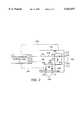
- FIG. 2is a schematic block diagram of a fail-over switching system of the present invention for use with a single data storage controller.
- FIGS. 3a and 3bare schematic diagrams showing the circuitry and behavior respectively of a prior art port bypass circuit.
- a data storage systemwill be configured with storage devices, where each storage device is connected to multiple different communication pathways.
- Data controllersare assigned to specified data storage devices and one of the pathways.
- the data controllerhandles data requests and responses respectively to and from the assigned storage devices over that pathway.
- the present inventionwill act as a bridge between the communication pathways such that if one pathway fails, then the affected data controller will be able to route its data requests over another available pathway.
- the present inventionmay be used to provide high-availability of a plurality of data storage devices.
- the storage deviceshave two communications ports for connection to two pathways.
- a multiplexing protocolmay be used to allow connecting multiple communication paths to a connection port.
- FIG. 1shows a preferred embodiment of the present invention as configured from the interconnection of two fail-over switches 100, 102.
- there is a dedicated data storage controller 90, 92 for each fail-over switchwhere the dedicated controller processes all data requests intended for the communication path to which the fail-over switch is attached, and where the controller may configure the fail-over switch to utilize its bypass terminals.
- Data requests for a data storage device 112can be sent by the first data storage controller 90 to a first incoming terminal 104 on the first fail-over switch 100 for transmission over a first communication path 126.
- the first communication pathis a loop in which data travels serially from point-to-point in a single direction around the loop.
- Data requests for a different data storage device 112may be sent by the second data storage controller 92 on a second incoming terminal 108 for transmission over a second communication path 128.
- the second communication pathis also a loop.
- the first and second communication pathsmay connect to numerous data storage devices limited by the speed of the path and the desired system speed. With a current Fibre Channel loop over one hundred data storage devices could be connected.
- the first data storage controller and the second data storage controllerare assigned to different storage devices to avoid arbitration and contention issues.
- the data storage controllers 90, 92receive responses to their requests respectively from the switches' outgoing terminals 106, 110.
- Each fail-over switchhas a transmission terminal 200 and a response terminal 202 for connection to opposite ends of the communication path loop.
- the fail-over switchesmay advantageously be switched to provide an alternate connection to an alternate loop.
- Each of the fail-over switchesinclude a bypass-transmission terminal 114 and a bypass-response terminal 116 for completing the alternate connection.
- the bypass terminals of the two switchesare cross-wired to each other so that the bypass-transmission terminal of one switch is connected to the bypass-response terminal of the other.
- the data storage controllersmay communicate with each other through a direct peer-to-peer communication link 150.
- the second data storage controller connected to an active communication pathwill diagnostically check the first data storage controller to ascertain whether the problem being experienced is actually the malfunction of the data storage controller rather than of its communication pathway. Only if the data storage controller checks out satisfactorily will the first switch 100 be directed to bypass its ordinarily assigned communication path and to route data requests through the second switch 102. Once communications have been re-routed, then both data storage controllers will be operating over the second communication path 128.
- the switchescan handle the failure of either communication path, switching the data storage controllers both into connection with the remaining active path.
- each fail-over switchincludes two port bypass circuits.
- a first bypass circuit 130connects the first incoming terminal 104 to the transmission terminal 200.
- the response terminal 202is connected to an intermediate node 132.
- a second bypass circuit 228connects the intermediate node 132 to the outgoing terminal 106.
- communications of the data storage controller 90take place over the first communication path 126.
- the first port bypass circuit 130severs the communication link between the first incoming terminal 104 and the transmission terminal 200.
- the first incoming terminal 104is connected to the intermediate node 132.
- the data request received on the incoming terminal 104is routed through the intermediate node 132 of the switch to the bypass-transmission terminal 114.
- the bypass-terminal 114is connected to the second switch's 102 incoming bypass-response terminal 116.
- the data received upon the bypass-response terminal 116is transmitted to the outgoing terminal 110 of the second data storage controller, and this data is automatically routed back to the incoming terminal 108 of the second controller.
- the automatic routingis practiced in the presently preferred embodiment in accordance with the protocol of the Fibre Channel arbitrated loop.
- devices connected to the communication pathwayarbitrate for the right to transmit over the pathway.
- the winner of the arbitrationmay then send out a request to communicate with another device connected to the pathway.
- the requested devicesends an acknowledgment and a point-to-point data path between the two devices is then formed.
- All other devices on the pathwayare required by the Fibre Channel specification to passively forward any data communications not intended for them, in effect, making all connectors to the pathway repeaters for all other connections on the pathway.
- the second data storage controllerpassively forwards data received on the second switch's 102 outgoing terminal 110 that was not intended for it back to the incoming terminal 108.
- the forwarded datamay then be processed upon the second communication path 128.
- returning data from the second communication path 128is directed by the second fail-over switch 102 from the response terminal 202 through the intermediate node 132 to the switch's bypass-transmission terminal 114.
- the bypass-transmission terminal 114is connected to the bypass-response terminal 116 of the first switch, and the data is made available to the first data storage controller at the outgoing terminal 106.
- FIG. 2shows the first fail-over switching system with only one data storage controller 90.
- the fail-over switch 100puts the data storage controller 90 in communication with the first communication path 126 or the second communication path 128.
- the second communication path 128must be routed through a second fail-over switch 102 or directly connected to the second path 128.
- Datais transmitted by the first fail-over switch 100 to the first communication path from a transmission terminal 200. Data is received from the loop over response terminal 202. When the fail-over switch is in its normal state, received data is directed through the intermediate node 132 across the second port bypass circuit 228 to the outgoing terminal 106. When the fail-over switch is switched, the first port bypass circuit 130 connects the incoming terminal 104 to the intermediate node 132. Data is transmitted to the second communication path 128 from bypass-transmission terminal 114. Data is received over bypass-response terminal 116. Thus, the fail-over switch permits communications by the data storage controller to proceed over either of the first communications loop 126 or the second communication loop 128. Thus, a problem on either loop can be accommodated by switching onto the other loop.
- the incoming terminal 104is connected to a data-in port 210 of the first port bypass circuit 130.
- a data-out port 216 of the first port bypass circuit 130is connected to the transmission terminal 200.
- the response terminal 202is connected to a response-in port 220 of the first port bypass circuit.
- a response-out port 224 of the first port bypass circuitis connected to a data-in port 226 of the second port bypass circuit 228.
- the term intermediate node 132 as used hereinrefers to the connection between the two port bypass circuits 130, 228.
- the bypass-transmission terminal 114is connected to a data-out port 232.
- the bypass-response terminal 116is connected to the response-in port 236.
- a response-out port 240is connected to the outgoing terminal 106 of the first fail-over switch 100.
- the state of the port bypass circuitsis controlled by the data storage controller 90.
- lines 242 and 244are shown to represent the control by the data storage controller 90 over the fail-over switches.
- Various intermediate controllersmay be used to carry out the instructions from the data storage controllers in alternate embodiments.
- a fail-over switchWhen a fail-over switch is in a switched bypass mode, communication through the incoming 104 and outgoing 106 terminals is routed through the bypass-transmission 114 and bypass-response 116 terminals instead of through the transmission 200 and response 202 terminals.
- the transmission 200 and response 202 terminalswould be in direct communication with the first communication path 126, while the bypass-transmission 204 and bypass-response 206 terminals may require communications to be routed through other hardware (e.g. the second fail-over switch 102 of FIG. 1) to reach the second communication path 128.
- FIG. 3ashows a logical circuit diagram of a prior-art port bypass circuit 300.
- FIG. 3bshows a behavioral diagram of such a port bypass circuit.
- These port bypass circuitsmay be used to make the fail-over switches used in the present invention.
- a port bypass circuithas two modes of operation, the first being a pass-through mode, and the second being a bypass-mode. The mode is controlled by the status of a control line 302 shown in FIG. 3a. If the control line indicates the pass-through mode, then data on a data transmission line 312 connected to the switch's data-in port 304 passes through the switch to exit on the switch's data-out port 310.
- response datais received on the switch's response-in port 306, and this data passes through the switch to a data response line 314 that is connected to the switch's response out port 308.
- control 302indicates the bypass-mode, then data entering the switch's data-in port 304 is routed directly to the switch's response-out port 308, thus bypassing the data-out 310 port.
Landscapes
- Engineering & Computer Science (AREA)
- Theoretical Computer Science (AREA)
- Quality & Reliability (AREA)
- Physics & Mathematics (AREA)
- General Engineering & Computer Science (AREA)
- General Physics & Mathematics (AREA)
- Small-Scale Networks (AREA)
- Data Exchanges In Wide-Area Networks (AREA)
- Hardware Redundancy (AREA)
Abstract
Description
Claims (33)
Priority Applications (8)
| Application Number | Priority Date | Filing Date | Title |
|---|---|---|---|
| US08/749,311US5922077A (en) | 1996-11-14 | 1996-11-14 | Fail-over switching system |
| JP52256798AJP3271669B2 (en) | 1996-11-14 | 1997-10-08 | Fail-over switching system |
| CA002264050ACA2264050A1 (en) | 1996-11-14 | 1997-10-08 | Fail-over switching system |
| EP97910942AEP0938705B1 (en) | 1996-11-14 | 1997-10-08 | Fail-over switching system |
| AU48200/97AAU4820097A (en) | 1996-11-14 | 1997-10-08 | Fail-over switching system |
| PCT/US1997/018522WO1998021657A1 (en) | 1996-11-14 | 1997-10-08 | Fail-over switching system |
| DE69715443TDE69715443T2 (en) | 1996-11-14 | 1997-10-08 | MEDIATION SYSTEM FOR SECURITY TRANSFER |
| US09/105,064US6128750A (en) | 1996-11-14 | 1998-06-26 | Fail-over switching system |
Applications Claiming Priority (1)
| Application Number | Priority Date | Filing Date | Title |
|---|---|---|---|
| US08/749,311US5922077A (en) | 1996-11-14 | 1996-11-14 | Fail-over switching system |
Related Child Applications (1)
| Application Number | Title | Priority Date | Filing Date |
|---|---|---|---|
| US09/105,064ContinuationUS6128750A (en) | 1996-11-14 | 1998-06-26 | Fail-over switching system |
Publications (1)
| Publication Number | Publication Date |
|---|---|
| US5922077Atrue US5922077A (en) | 1999-07-13 |
Family
ID=25013205
Family Applications (2)
| Application Number | Title | Priority Date | Filing Date |
|---|---|---|---|
| US08/749,311Expired - LifetimeUS5922077A (en) | 1996-11-14 | 1996-11-14 | Fail-over switching system |
| US09/105,064Expired - LifetimeUS6128750A (en) | 1996-11-14 | 1998-06-26 | Fail-over switching system |
Family Applications After (1)
| Application Number | Title | Priority Date | Filing Date |
|---|---|---|---|
| US09/105,064Expired - LifetimeUS6128750A (en) | 1996-11-14 | 1998-06-26 | Fail-over switching system |
Country Status (7)
| Country | Link |
|---|---|
| US (2) | US5922077A (en) |
| EP (1) | EP0938705B1 (en) |
| JP (1) | JP3271669B2 (en) |
| AU (1) | AU4820097A (en) |
| CA (1) | CA2264050A1 (en) |
| DE (1) | DE69715443T2 (en) |
| WO (1) | WO1998021657A1 (en) |
Cited By (78)
| Publication number | Priority date | Publication date | Assignee | Title |
|---|---|---|---|---|
| US6128750A (en)* | 1996-11-14 | 2000-10-03 | Emc Corporation | Fail-over switching system |
| US6289376B1 (en)* | 1999-03-31 | 2001-09-11 | Diva Systems Corp. | Tightly-coupled disk-to-CPU storage server |
| US20010056304A1 (en)* | 2000-04-19 | 2001-12-27 | Kabushiki Kaisha Toshiba | Field apparatus control system and computer-readable storage medium |
| US6338110B1 (en)* | 1997-11-14 | 2002-01-08 | Sun Microsystems, Inc. | Partitioning of storage channels using programmable switches |
| US6356984B1 (en)* | 1998-06-30 | 2002-03-12 | Sun Microsystems, Inc. | Digital data processing system having a data bus and a control bus |
| US6393535B1 (en) | 2000-05-02 | 2002-05-21 | International Business Machines Corporation | Method, system, and program for modifying preferred path assignments to a storage device |
| US20020087912A1 (en)* | 2000-12-29 | 2002-07-04 | International Business Machines Corporation | Highly available TCP systems with fail over connections |
| US6459701B1 (en) | 1999-08-06 | 2002-10-01 | Emulex Corporation | Variable access fairness in a fibre channel arbitrated loop |
| US6473868B1 (en)* | 1998-06-10 | 2002-10-29 | Nec Corporation | Disc array connection system, detection method of malfunctioning device and recording medium having control program recorded thereon |
| US6504817B2 (en)* | 1997-03-31 | 2003-01-07 | Hewlett-Packard Company | Fiber channel arbitrated loop dynamic loop sizing |
| US6560683B1 (en) | 1999-12-29 | 2003-05-06 | Emc Corporation | Fibre channel data storage system having improved rear-end I/O adapted hub |
| US6567890B1 (en) | 1999-06-30 | 2003-05-20 | Emc Corporation | Fibre channel port by-pass selector section for dual ported disk drives |
| US6571355B1 (en)* | 1999-12-29 | 2003-05-27 | Emc Corporation | Fibre channel data storage system fail-over mechanism |
| US6574687B1 (en)* | 1999-12-29 | 2003-06-03 | Emc Corporation | Fibre channel data storage system |
| US6574753B1 (en) | 2000-01-10 | 2003-06-03 | Emc Corporation | Peer link fault isolation |
| US6578158B1 (en) | 1999-10-28 | 2003-06-10 | International Business Machines Corporation | Method and apparatus for providing a raid controller having transparent failover and failback |
| US6581136B1 (en) | 1999-06-30 | 2003-06-17 | Emc Corporation | Fibre channel data storage system having expansion/contraction |
| US6591324B1 (en)* | 2000-07-12 | 2003-07-08 | Nexcom International Co. Ltd. | Hot swap processor card and bus |
| US20030135642A1 (en)* | 2001-12-21 | 2003-07-17 | Andiamo Systems, Inc. | Methods and apparatus for implementing a high availability fibre channel switch |
| US20030135671A1 (en)* | 2002-01-17 | 2003-07-17 | International Business Machines Corporation | External storage device, control device, external storage system, control method, program, and recording medium |
| US6601128B1 (en) | 2000-05-02 | 2003-07-29 | International Business Machines Corporation | Method, system, program, and data structure for selecting a preferred path to a storage device |
| US20030154431A1 (en)* | 2002-02-14 | 2003-08-14 | Lin Steven Tzu-Yun | Method for recovering from malfunctions in an agent module of a modular network device |
| US6615315B1 (en)* | 1999-12-29 | 2003-09-02 | Emc Corporation | Fibre channel data storage system having improved fro-end I/O adapted hub |
| US6629216B1 (en) | 1999-06-30 | 2003-09-30 | Emc Corporation | Fibre channel by-pass |
| US6636934B1 (en) | 1999-06-30 | 2003-10-21 | Emc Corporation | Fiber channel port by-pass selector section for dual ported disk drives |
| US20030221124A1 (en)* | 2002-05-23 | 2003-11-27 | International Business Machines Corporation | File level security for a metadata controller in a storage area network |
| US20030220923A1 (en)* | 2002-05-23 | 2003-11-27 | International Business Machines Corporation | Mechanism for running parallel application programs on metadata controller nodes |
| US20030220943A1 (en)* | 2002-05-23 | 2003-11-27 | International Business Machines Corporation | Recovery of a single metadata controller failure in a storage area network environment |
| US6704812B2 (en)* | 2000-11-30 | 2004-03-09 | International Business Machines Corporation | Transparent and dynamic management of redundant physical paths to peripheral devices |
| US6732289B1 (en)* | 2000-08-31 | 2004-05-04 | Sun Microsystems, Inc. | Fault tolerant data storage system |
| US20040107320A1 (en)* | 2002-11-08 | 2004-06-03 | International Business Machines Corporation | Control path failover in an automated data storage library |
| US6766482B1 (en) | 2001-10-31 | 2004-07-20 | Extreme Networks | Ethernet automatic protection switching |
| US6769072B1 (en)* | 1999-09-14 | 2004-07-27 | Fujitsu Limited | Distributed processing system with registered reconfiguration processors and registered notified processors |
| US20040172489A1 (en)* | 2002-12-20 | 2004-09-02 | Fujitsu Limited | Storage system and disconnecting method of a faulty storage device |
| US6820212B2 (en) | 2001-02-20 | 2004-11-16 | Digi-Data Corporation | RAID system having channel capacity unaffected by any single component failure |
| US20050010843A1 (en)* | 2003-07-11 | 2005-01-13 | Koji Iwamitsu | Storage system and a method for diagnosing failure of the storage system |
| US20050028069A1 (en)* | 2003-07-31 | 2005-02-03 | Larry Thayer | Memory system and controller for same |
| US20050058063A1 (en)* | 2003-09-15 | 2005-03-17 | Dell Products L.P. | Method and system supporting real-time fail-over of network switches |
| US6898730B1 (en) | 2001-11-30 | 2005-05-24 | Western Digital Technologies, Inc. | System and method for fail-over switching in a disk storage medium |
| US20050138221A1 (en)* | 2003-12-23 | 2005-06-23 | Intel Corporation | Handling redundant paths among devices |
| US6963941B1 (en)* | 2000-05-31 | 2005-11-08 | Micron Technology, Inc. | High speed bus topology for expandable systems |
| US20050278581A1 (en)* | 2004-05-27 | 2005-12-15 | Xiaoming Jiang | Storage control system and operating method for storage control system |
| US6980510B1 (en) | 2000-09-12 | 2005-12-27 | International Business Machines Corporation | Host interface adaptive hub storage system |
| US20060123273A1 (en)* | 2004-11-15 | 2006-06-08 | Kalos Matthew J | Reassigning storage volumes from a failed processing system to a surviving processing system |
| EP1712997A1 (en)* | 2005-04-13 | 2006-10-18 | Hitachi, Ltd. | Disk array device and control method therefor |
| US20070016751A1 (en)* | 2000-08-01 | 2007-01-18 | Hitachi, Ltd. | File system |
| US7228538B1 (en) | 2000-05-02 | 2007-06-05 | International Business Machines Corporation | Method, system, and program for updating firmware to a storage system comprised of multiple controllers |
| US20080184020A1 (en)* | 2007-01-25 | 2008-07-31 | International Business Machines Corporation | Apparatus and method to update firmware disposed in multiple devices sharing a common address in a computing system |
| US7861107B1 (en)* | 2006-08-14 | 2010-12-28 | Network Appliance, Inc. | Dual access pathways to serially-connected mass data storage units |
| US8140622B2 (en) | 2002-05-23 | 2012-03-20 | International Business Machines Corporation | Parallel metadata service in storage area network environment |
| US20120224526A1 (en)* | 2009-11-18 | 2012-09-06 | Nec Corporation | Relay apparatus, and relay method and program |
| US8401214B2 (en) | 2009-06-18 | 2013-03-19 | Earlens Corporation | Eardrum implantable devices for hearing systems and methods |
| US8715154B2 (en) | 2009-06-24 | 2014-05-06 | Earlens Corporation | Optically coupled cochlear actuator systems and methods |
| US8715153B2 (en) | 2009-06-22 | 2014-05-06 | Earlens Corporation | Optically coupled bone conduction systems and methods |
| US9055379B2 (en) | 2009-06-05 | 2015-06-09 | Earlens Corporation | Optically coupled acoustic middle ear implant systems and methods |
| US20150199245A1 (en)* | 2014-01-14 | 2015-07-16 | Yokogawa Electric Corporation | Instrumentation system and method for maintaining the same |
| US9544700B2 (en) | 2009-06-15 | 2017-01-10 | Earlens Corporation | Optically coupled active ossicular replacement prosthesis |
| US9749758B2 (en) | 2008-09-22 | 2017-08-29 | Earlens Corporation | Devices and methods for hearing |
| US9924276B2 (en) | 2014-11-26 | 2018-03-20 | Earlens Corporation | Adjustable venting for hearing instruments |
| US9930458B2 (en) | 2014-07-14 | 2018-03-27 | Earlens Corporation | Sliding bias and peak limiting for optical hearing devices |
| US9949039B2 (en) | 2005-05-03 | 2018-04-17 | Earlens Corporation | Hearing system having improved high frequency response |
| US9961454B2 (en) | 2008-06-17 | 2018-05-01 | Earlens Corporation | Optical electro-mechanical hearing devices with separate power and signal components |
| US10034103B2 (en) | 2014-03-18 | 2018-07-24 | Earlens Corporation | High fidelity and reduced feedback contact hearing apparatus and methods |
| US10154352B2 (en) | 2007-10-12 | 2018-12-11 | Earlens Corporation | Multifunction system and method for integrated hearing and communication with noise cancellation and feedback management |
| US10178483B2 (en) | 2015-12-30 | 2019-01-08 | Earlens Corporation | Light based hearing systems, apparatus, and methods |
| US10284964B2 (en) | 2010-12-20 | 2019-05-07 | Earlens Corporation | Anatomically customized ear canal hearing apparatus |
| US10286215B2 (en) | 2009-06-18 | 2019-05-14 | Earlens Corporation | Optically coupled cochlear implant systems and methods |
| US10292601B2 (en) | 2015-10-02 | 2019-05-21 | Earlens Corporation | Wearable customized ear canal apparatus |
| US10365981B2 (en)* | 2016-08-19 | 2019-07-30 | Samsung Electronics Co., Ltd. | Adaptive multipath fabric for balanced performance and high availability |
| US10492010B2 (en) | 2015-12-30 | 2019-11-26 | Earlens Corporations | Damping in contact hearing systems |
| US10555100B2 (en) | 2009-06-22 | 2020-02-04 | Earlens Corporation | Round window coupled hearing systems and methods |
| US11102594B2 (en) | 2016-09-09 | 2021-08-24 | Earlens Corporation | Contact hearing systems, apparatus and methods |
| US11166114B2 (en) | 2016-11-15 | 2021-11-02 | Earlens Corporation | Impression procedure |
| US11212626B2 (en) | 2018-04-09 | 2021-12-28 | Earlens Corporation | Dynamic filter |
| US11350226B2 (en) | 2015-12-30 | 2022-05-31 | Earlens Corporation | Charging protocol for rechargeable hearing systems |
| US20220261165A1 (en)* | 2021-02-12 | 2022-08-18 | Western Digital Technologies, Inc. | Disaggregation of control path and data path |
| US11516603B2 (en) | 2018-03-07 | 2022-11-29 | Earlens Corporation | Contact hearing device and retention structure materials |
| US11734131B2 (en)* | 2020-04-09 | 2023-08-22 | Micron Technology, Inc. | Memory device having redundant media management capabilities |
Families Citing this family (69)
| Publication number | Priority date | Publication date | Assignee | Title |
|---|---|---|---|---|
| WO1999063442A1 (en)* | 1998-06-05 | 1999-12-09 | Mylex Corporation | Fibre channel topological structure and method and application with raid devices and controllers |
| US6477139B1 (en) | 1998-11-15 | 2002-11-05 | Hewlett-Packard Company | Peer controller management in a dual controller fibre channel storage enclosure |
| JP3196843B2 (en)* | 1998-12-02 | 2001-08-06 | 日本電気株式会社 | System and method for detecting / eliminating a failed port in a fiber channel arbitration loop |
| US6230217B1 (en)* | 1998-12-30 | 2001-05-08 | Raytheon Company | Data storage system having a host computer coupled to bank of disk drives through interface comprising plurality of directors, buses, and a PCB connectors |
| US6324613B1 (en)* | 1999-01-05 | 2001-11-27 | Agere Systems Guardian Corp. | Port router |
| US6219753B1 (en) | 1999-06-04 | 2001-04-17 | International Business Machines Corporation | Fiber channel topological structure and method including structure and method for raid devices and controllers |
| JP2001216206A (en)* | 2000-02-01 | 2001-08-10 | Nec Corp | Fault analysis method for loop-like interface, and system provided with fault analysis function |
| US6772270B1 (en)* | 2000-02-10 | 2004-08-03 | Vicom Systems, Inc. | Multi-port fibre channel controller |
| US6877044B2 (en)* | 2000-02-10 | 2005-04-05 | Vicom Systems, Inc. | Distributed storage management platform architecture |
| US6708283B1 (en) | 2000-04-13 | 2004-03-16 | Stratus Technologies, Bermuda Ltd. | System and method for operating a system with redundant peripheral bus controllers |
| US6735715B1 (en)* | 2000-04-13 | 2004-05-11 | Stratus Technologies Bermuda Ltd. | System and method for operating a SCSI bus with redundant SCSI adaptors |
| US6775230B1 (en)* | 2000-07-18 | 2004-08-10 | Hitachi, Ltd. | Apparatus and method for transmitting frames via a switch in a storage area network |
| US6725393B1 (en)* | 2000-11-06 | 2004-04-20 | Hewlett-Packard Development Company, L.P. | System, machine, and method for maintenance of mirrored datasets through surrogate writes during storage-area network transients |
| US7290277B1 (en)* | 2002-01-24 | 2007-10-30 | Avago Technologies General Ip Pte Ltd | Control of authentication data residing in a network device |
| US20030217211A1 (en)* | 2002-05-14 | 2003-11-20 | Rust Robert A. | Controller communications over an always-on controller interconnect |
| US6959312B2 (en)* | 2002-05-30 | 2005-10-25 | International Business Machines Corporation | Fast provisioning of storage in a network of production computers for minimizing inter-customer delay |
| WO2004013719A2 (en)* | 2002-08-02 | 2004-02-12 | Grass Valley (U.S) Inc. | Real-time fail-over recovery for a media area network |
| CA2498174C (en) | 2002-09-09 | 2010-04-13 | Commvault Systems, Inc. | Dynamic storage device pooling in a computer system |
| US20040054765A1 (en)* | 2002-09-12 | 2004-03-18 | Dwyer Thomas J. | Method and apparatus for accessing multiple system controllers within a computer system |
| US7360099B2 (en)* | 2002-09-19 | 2008-04-15 | Tripwire, Inc. | Computing environment and apparatuses with integrity based fail over |
| KR20100072067A (en)* | 2002-10-31 | 2010-06-29 | 링 테크노로지 엔터프라이즈, 엘엘씨 | Methods and systems for a storage system |
| US7707307B2 (en)* | 2003-01-09 | 2010-04-27 | Cisco Technology, Inc. | Method and apparatus for constructing a backup route in a data communications network |
| US7362697B2 (en)* | 2003-01-09 | 2008-04-22 | International Business Machines Corporation | Self-healing chip-to-chip interface |
| US7869350B1 (en) | 2003-01-15 | 2011-01-11 | Cisco Technology, Inc. | Method and apparatus for determining a data communication network repair strategy |
| AU2004227949B9 (en) | 2003-04-03 | 2010-07-22 | Commvault Systems, Inc. | System and method for dynamically performing storage operations in a computer network |
| US7646705B2 (en)* | 2003-04-11 | 2010-01-12 | International Business Machines Corporation | Minimizing data loss chances during controller switching |
| US7330440B1 (en)* | 2003-05-20 | 2008-02-12 | Cisco Technology, Inc. | Method and apparatus for constructing a transition route in a data communications network |
| US7200787B2 (en)* | 2003-06-03 | 2007-04-03 | Intel Corporation | Memory channel utilizing permuting status patterns |
| US7194581B2 (en)* | 2003-06-03 | 2007-03-20 | Intel Corporation | Memory channel with hot add/remove |
| US7127629B2 (en)* | 2003-06-03 | 2006-10-24 | Intel Corporation | Redriving a data signal responsive to either a sampling clock signal or stable clock signal dependent on a mode signal |
| US7165153B2 (en) | 2003-06-04 | 2007-01-16 | Intel Corporation | Memory channel with unidirectional links |
| US8171331B2 (en) | 2003-06-04 | 2012-05-01 | Intel Corporation | Memory channel having deskew separate from redrive |
| US7340537B2 (en)* | 2003-06-04 | 2008-03-04 | Intel Corporation | Memory channel with redundant presence detect |
| US7386768B2 (en)* | 2003-06-05 | 2008-06-10 | Intel Corporation | Memory channel with bit lane fail-over |
| US7864708B1 (en) | 2003-07-15 | 2011-01-04 | Cisco Technology, Inc. | Method and apparatus for forwarding a tunneled packet in a data communications network |
| JP4080970B2 (en)* | 2003-07-30 | 2008-04-23 | 株式会社日立製作所 | Switch that provides path switching |
| US7210058B2 (en)* | 2003-09-29 | 2007-04-24 | International Business Machines Corporation | Method for peer-to-peer system recovery |
| US7554921B2 (en) | 2003-10-14 | 2009-06-30 | Cisco Technology, Inc. | Method and apparatus for generating routing information in a data communication network |
| US7580360B2 (en) | 2003-10-14 | 2009-08-25 | Cisco Technology, Inc. | Method and apparatus for generating routing information in a data communications network |
| US7143207B2 (en)* | 2003-11-14 | 2006-11-28 | Intel Corporation | Data accumulation between data path having redrive circuit and memory device |
| US7447953B2 (en)* | 2003-11-14 | 2008-11-04 | Intel Corporation | Lane testing with variable mapping |
| US7219294B2 (en)* | 2003-11-14 | 2007-05-15 | Intel Corporation | Early CRC delivery for partial frame |
| US7428213B2 (en)* | 2003-11-21 | 2008-09-23 | Cisco Technology, Inc. | Method and apparatus for determining network routing information based on shared risk link group information |
| US7444558B2 (en)* | 2003-12-31 | 2008-10-28 | Intel Corporation | Programmable measurement mode for a serial point to point link |
| US7710882B1 (en) | 2004-03-03 | 2010-05-04 | Cisco Technology, Inc. | Method and apparatus for computing routing information for a data communications network |
| US7512830B2 (en)* | 2004-05-14 | 2009-03-31 | International Business Machines Corporation | Management module failover across multiple blade center chassis |
| US7202722B2 (en)* | 2004-05-17 | 2007-04-10 | Agere System Inc. | Duty-cycle correction circuit |
| US7212423B2 (en)* | 2004-05-31 | 2007-05-01 | Intel Corporation | Memory agent core clock aligned to lane |
| US7848240B2 (en) | 2004-06-01 | 2010-12-07 | Cisco Technology, Inc. | Method and apparatus for forwarding data in a data communications network |
| US7383399B2 (en) | 2004-06-30 | 2008-06-03 | Intel Corporation | Method and apparatus for memory compression |
| US7630298B2 (en)* | 2004-10-27 | 2009-12-08 | Cisco Technology, Inc. | Method and apparatus for forwarding data in a data communications network |
| US7500053B1 (en) | 2004-11-05 | 2009-03-03 | Commvvault Systems, Inc. | Method and system for grouping storage system components |
| US7536291B1 (en) | 2004-11-08 | 2009-05-19 | Commvault Systems, Inc. | System and method to support simulated storage operations |
| US20060143502A1 (en)* | 2004-12-10 | 2006-06-29 | Dell Products L.P. | System and method for managing failures in a redundant memory subsystem |
| US7933197B2 (en) | 2005-02-22 | 2011-04-26 | Cisco Technology, Inc. | Method and apparatus for constructing a repair path around a non-available component in a data communications network |
| US7848224B2 (en) | 2005-07-05 | 2010-12-07 | Cisco Technology, Inc. | Method and apparatus for constructing a repair path for multicast data |
| US7835312B2 (en)* | 2005-07-20 | 2010-11-16 | Cisco Technology, Inc. | Method and apparatus for updating label-switched paths |
| JP4782524B2 (en)* | 2005-09-29 | 2011-09-28 | 株式会社東芝 | Semiconductor integrated circuit, design support software system, and test pattern automatic generation system |
| US7404055B2 (en) | 2006-03-28 | 2008-07-22 | Intel Corporation | Memory transfer with early access to critical portion |
| US7792019B1 (en)* | 2006-06-22 | 2010-09-07 | Verizon Patent And Licensing Inc. | Call management |
| GB0612482D0 (en)* | 2006-06-23 | 2006-08-02 | Ibm | Apparatus and method for controlling raid array rebuild |
| US8305879B2 (en)* | 2007-03-30 | 2012-11-06 | International Business Machines Corporation | Peripheral component switch having automatic link failover |
| US7940776B2 (en) | 2007-06-13 | 2011-05-10 | Cisco Technology, Inc. | Fast re-routing in distance vector routing protocol networks |
| US7788530B2 (en)* | 2007-06-27 | 2010-08-31 | International Business Machines Corporation | Storage server configuration despite an out-of-service storage adapter |
| US8542578B1 (en) | 2010-08-04 | 2013-09-24 | Cisco Technology, Inc. | System and method for providing a link-state path to a node in a network environment |
| US8966187B2 (en) | 2011-12-01 | 2015-02-24 | International Business Machines Corporation | Flexible replication with skewed mapping in multi-core chips |
| US10303637B2 (en) | 2015-08-20 | 2019-05-28 | Toshiba Memory Corporation | Storage system including a plurality of storage devices arranged in a holder |
| CN111879310A (en)* | 2020-07-24 | 2020-11-03 | 闽江学院 | Crowd emergency evacuation simulation method based on invasive weed optimization algorithm |
| US11593223B1 (en) | 2021-09-02 | 2023-02-28 | Commvault Systems, Inc. | Using resource pool administrative entities in a data storage management system to provide shared infrastructure to tenants |
Citations (23)
| Publication number | Priority date | Publication date | Assignee | Title |
|---|---|---|---|---|
| US4371754A (en)* | 1980-11-19 | 1983-02-01 | Rockwell International Corporation | Automatic fault recovery system for a multiple processor telecommunications switching control |
| US4594709A (en)* | 1982-08-25 | 1986-06-10 | Nec Corporation | Data transmission device for loop transmission system |
| US4627055A (en)* | 1984-01-09 | 1986-12-02 | Hitachi, Ltd. | Decentralized processing method and system |
| US4958273A (en)* | 1987-08-26 | 1990-09-18 | International Business Machines Corporation | Multiprocessor system architecture with high availability |
| US5003531A (en)* | 1989-08-11 | 1991-03-26 | Infotron Systems Corporation | Survivable network using reverse protection ring |
| WO1991013399A1 (en)* | 1990-03-02 | 1991-09-05 | Sf2 Corporation | Disk array system |
| US5155845A (en)* | 1990-06-15 | 1992-10-13 | Storage Technology Corporation | Data storage system for providing redundant copies of data on different disk drives |
| US5168443A (en)* | 1990-09-26 | 1992-12-01 | Honeywell Inc. | Method for providing redundancy of a high speed pulse input I/O processor |
| US5202887A (en)* | 1989-06-21 | 1993-04-13 | Hitachi, Ltd. | Access control method for shared duplex direct access storage device and computer system therefor |
| US5212785A (en)* | 1990-04-06 | 1993-05-18 | Micro Technology, Inc. | Apparatus and method for controlling data flow between a computer and memory devices |
| US5343477A (en)* | 1990-09-17 | 1994-08-30 | Omron Corporation | Data processing system with data transmission failure recovery measures |
| US5485576A (en)* | 1994-01-28 | 1996-01-16 | Fee; Brendan | Chassis fault tolerant system management bus architecture for a networking |
| US5487062A (en)* | 1993-04-19 | 1996-01-23 | Hitachi, Ltd. | Looped bus system for connecting plural nodes or plural circuit cards |
| US5515501A (en)* | 1994-01-21 | 1996-05-07 | Unisys Corporation | Redundant maintenance architecture |
| US5544339A (en)* | 1992-01-07 | 1996-08-06 | Mitsubishi Denki Kabushiki Kaisha | Array of disk drives with redundant channels |
| US5544330A (en)* | 1994-07-13 | 1996-08-06 | Emc Corporation | Fault tolerant interconnect topology using multiple rings |
| US5546535A (en)* | 1992-03-13 | 1996-08-13 | Emc Corporation | Multiple controller sharing in a redundant storage array |
| US5548711A (en)* | 1993-08-26 | 1996-08-20 | Emc Corporation | Method and apparatus for fault tolerant fast writes through buffer dumping |
| EP0751464A1 (en)* | 1995-06-26 | 1997-01-02 | Hewlett-Packard Company | Storage system |
| WO1997007458A1 (en)* | 1995-08-15 | 1997-02-27 | Emc Corporation | Data storage system |
| US5617425A (en)* | 1993-05-26 | 1997-04-01 | Seagate Technology, Inc. | Disc array having array supporting controllers and interface |
| US5655150A (en)* | 1991-04-11 | 1997-08-05 | Mitsubishi Denki Kabushiki Kaisha | Recording device having alternative recording units operated in three different conditions depending on activities in maintenance diagnosis mechanism and recording sections |
| US5668943A (en)* | 1994-10-31 | 1997-09-16 | International Business Machines Corporation | Virtual shared disks with application transparent recovery |
Family Cites Families (8)
| Publication number | Priority date | Publication date | Assignee | Title |
|---|---|---|---|---|
| JPH0618377B2 (en)* | 1983-09-08 | 1994-03-09 | 株式会社日立製作所 | Transmission system |
| US5200051A (en)* | 1988-11-14 | 1993-04-06 | I-Stat Corporation | Wholly microfabricated biosensors and process for the manufacture and use thereof |
| US4999829A (en)* | 1989-11-06 | 1991-03-12 | At&T Bell Laboratories | Automatic fault recovery in a packet network |
| US4993015A (en)* | 1989-11-06 | 1991-02-12 | At&T Bell Laboratories | Automatic fault recovery in a packet network |
| US5016243A (en)* | 1989-11-06 | 1991-05-14 | At&T Bell Laboratories | Automatic fault recovery in a packet network |
| JP3120157B2 (en)* | 1991-07-08 | 2000-12-25 | 株式会社日立製作所 | Loop logical channel control method |
| AU1883995A (en)* | 1994-03-08 | 1995-09-25 | Excel, Inc. | Telecommunications switch with improved redundancy |
| US5922077A (en)* | 1996-11-14 | 1999-07-13 | Data General Corporation | Fail-over switching system |
- 1996
- 1996-11-14USUS08/749,311patent/US5922077A/ennot_activeExpired - Lifetime
- 1997
- 1997-10-08AUAU48200/97Apatent/AU4820097A/ennot_activeAbandoned
- 1997-10-08WOPCT/US1997/018522patent/WO1998021657A1/enactiveIP Right Grant
- 1997-10-08JPJP52256798Apatent/JP3271669B2/ennot_activeExpired - Fee Related
- 1997-10-08EPEP97910942Apatent/EP0938705B1/ennot_activeExpired - Lifetime
- 1997-10-08DEDE69715443Tpatent/DE69715443T2/ennot_activeExpired - Lifetime
- 1997-10-08CACA002264050Apatent/CA2264050A1/ennot_activeAbandoned
- 1998
- 1998-06-26USUS09/105,064patent/US6128750A/ennot_activeExpired - Lifetime
Patent Citations (24)
| Publication number | Priority date | Publication date | Assignee | Title |
|---|---|---|---|---|
| US4371754A (en)* | 1980-11-19 | 1983-02-01 | Rockwell International Corporation | Automatic fault recovery system for a multiple processor telecommunications switching control |
| US4594709A (en)* | 1982-08-25 | 1986-06-10 | Nec Corporation | Data transmission device for loop transmission system |
| US4627055A (en)* | 1984-01-09 | 1986-12-02 | Hitachi, Ltd. | Decentralized processing method and system |
| US4958273A (en)* | 1987-08-26 | 1990-09-18 | International Business Machines Corporation | Multiprocessor system architecture with high availability |
| US5202887A (en)* | 1989-06-21 | 1993-04-13 | Hitachi, Ltd. | Access control method for shared duplex direct access storage device and computer system therefor |
| US5003531A (en)* | 1989-08-11 | 1991-03-26 | Infotron Systems Corporation | Survivable network using reverse protection ring |
| WO1991013399A1 (en)* | 1990-03-02 | 1991-09-05 | Sf2 Corporation | Disk array system |
| US5212785A (en)* | 1990-04-06 | 1993-05-18 | Micro Technology, Inc. | Apparatus and method for controlling data flow between a computer and memory devices |
| US5651110A (en)* | 1990-04-06 | 1997-07-22 | Micro Technology Corp. | Apparatus and method for controlling data flow between a computer and memory devices |
| US5155845A (en)* | 1990-06-15 | 1992-10-13 | Storage Technology Corporation | Data storage system for providing redundant copies of data on different disk drives |
| US5343477A (en)* | 1990-09-17 | 1994-08-30 | Omron Corporation | Data processing system with data transmission failure recovery measures |
| US5168443A (en)* | 1990-09-26 | 1992-12-01 | Honeywell Inc. | Method for providing redundancy of a high speed pulse input I/O processor |
| US5655150A (en)* | 1991-04-11 | 1997-08-05 | Mitsubishi Denki Kabushiki Kaisha | Recording device having alternative recording units operated in three different conditions depending on activities in maintenance diagnosis mechanism and recording sections |
| US5544339A (en)* | 1992-01-07 | 1996-08-06 | Mitsubishi Denki Kabushiki Kaisha | Array of disk drives with redundant channels |
| US5546535A (en)* | 1992-03-13 | 1996-08-13 | Emc Corporation | Multiple controller sharing in a redundant storage array |
| US5487062A (en)* | 1993-04-19 | 1996-01-23 | Hitachi, Ltd. | Looped bus system for connecting plural nodes or plural circuit cards |
| US5617425A (en)* | 1993-05-26 | 1997-04-01 | Seagate Technology, Inc. | Disc array having array supporting controllers and interface |
| US5548711A (en)* | 1993-08-26 | 1996-08-20 | Emc Corporation | Method and apparatus for fault tolerant fast writes through buffer dumping |
| US5515501A (en)* | 1994-01-21 | 1996-05-07 | Unisys Corporation | Redundant maintenance architecture |
| US5485576A (en)* | 1994-01-28 | 1996-01-16 | Fee; Brendan | Chassis fault tolerant system management bus architecture for a networking |
| US5544330A (en)* | 1994-07-13 | 1996-08-06 | Emc Corporation | Fault tolerant interconnect topology using multiple rings |
| US5668943A (en)* | 1994-10-31 | 1997-09-16 | International Business Machines Corporation | Virtual shared disks with application transparent recovery |
| EP0751464A1 (en)* | 1995-06-26 | 1997-01-02 | Hewlett-Packard Company | Storage system |
| WO1997007458A1 (en)* | 1995-08-15 | 1997-02-27 | Emc Corporation | Data storage system |
Non-Patent Citations (24)
| Title |
|---|
| "Data Storage Just Got 10×Faster -Introducting Box Hill's Fibre Box™", Oct. 1996 Silicon Alley, Product Description. http: / /www.boxhill.com/fibrebox/press.html. |
| "Disk Array Reliability is Improving", Ann Miller, CMP Media, Inc., May 23, 1994, http: / /192.216.191.76/cg . . . =125888&CO-- CD=1&CO-- TXT=Y. |
| "Disk Servers and RAID", A Comparative Overview from Computing Edge, Computing Edge Corporation, 1996. |
| "Fibre Channel: The Digital Highway Made Practical", Tim Sutton, David Webb, Oct. 22, 1994, Seagate Technology Paper. http / /www.seagate.com/s . . . r/fibchan/fibchantp.html. |
| "Fibre Channel-Arbitrated Loop Active Hub", FCL1063TW, Product Description. http: / /www.gadzoox.com/FCL1063.htm. |
| "High Availability: Stayin'Alive --High availability storage clusters offer customers near fault tolerance and offer VARs better margins than RAID", Peter Jordan, Apr. 15, 1996, 1996 CMP Publications, Inc. http: / /192.216.191.76/cg . . . =125596&CO-- CD=4&CO-- TXT=Y. |
| "In-Depth Fibre Channel Arbitrated Loop", R.W. Kembel, Northwest Learning Associates for Solution Technology. |
| "Tandem Expands Leading Fault-Tolerant Unix(r) Systems Offerings and Adds Complementary Servers and Workstations", Tandem Computers, Inc., Oct. 18, 1996. http:/ /www.tandem.com/press-releases/integrity.html. |
| Channel Networking: Networking Flexibility with Channel Speeds Using . . . , Fibre Channel. http: / /www.ancor.com/chnlnet.htm.* |
| Ciprico Annual Report, 1995.* |
| Ciprico Disk Arrays, Product Description, 1995.* |
| CLARiiON, Data General Corporation, Product Description, 1995.* |
| Data Storage Just Got 10 Faster Introducting Box Hill s Fibre Box , Oct. 1996 Silicon Alley, Product Description. http: / /www.boxhill.com/fibrebox/press.html.* |
| Disk Array Reliability is Improving , Ann Miller, CMP Media, Inc., May 23, 1994, http: / /192.216.191.76/cg . . . 125888&CO CD 1&CO TXT Y.* |
| Disk Servers and RAID , A Comparative Overview from Computing Edge, Computing Edge Corporation, 1996.* |
| Fibre Channel Arbitrated Loop Active Hub , FCL1063TW, Product Description. http: / /www.gadzoox.com/FCL1063.htm.* |
| Fibre Channel Association. http: / /www.Amdahl.com/ext/CARP/FCA/FCA.html.* |
| Fibre Channel: The Digital Highway Made Practical , Tim Sutton, David Webb, Oct. 22, 1994, Seagate Technology Paper. http / /www.seagate.com/s . . . r/fibchan/fibchantp.html.* |
| High Availability: Stayin Alive High availability storage clusters offer customers near fault tolerance and offer VARs better margins than RAID , Peter Jordan, Apr. 15, 1996, 1996 CMP Publications, Inc. http: / /192.216.191.76/cg . . . 125596&CO CD 4&CO TXT Y.* |
| In Depth Fibre Channel Arbitrated Loop , R.W. Kembel, Northwest Learning Associates for Solution Technology .* |
| Integrity S4000 Servers: CO Models, Tandem Computers, Inc., Sep. 1995. http:/ /www.tandem.com/INFOCTR/PROD DES/ITS4COPD/ITS4COPD.HTM.* |
| Meltek FC Array, Product Description. http: / / www.meltek.com/fibre/fca.html.* |
| Meltek FC-Array, Product Description. http: / / www.meltek.com/fibre/fca.html. |
| Tandem Expands Leading Fault Tolerant Unix(r) Systems Offerings and Adds Complementary Servers and Workstations , Tandem Computers, Inc., Oct. 18, 1996. http:/ /www.tandem.com/press releases/integrity.html.* |
Cited By (142)
| Publication number | Priority date | Publication date | Assignee | Title |
|---|---|---|---|---|
| US6128750A (en)* | 1996-11-14 | 2000-10-03 | Emc Corporation | Fail-over switching system |
| US6504817B2 (en)* | 1997-03-31 | 2003-01-07 | Hewlett-Packard Company | Fiber channel arbitrated loop dynamic loop sizing |
| US20020019897A1 (en)* | 1997-11-14 | 2002-02-14 | Sun Microsystems, Inc. | Partitioning of storage channels using programmable switches |
| US6983343B2 (en) | 1997-11-14 | 2006-01-03 | Sun Microsystems, Inc. | Partitioning of storage channels using programmable switches |
| US6338110B1 (en)* | 1997-11-14 | 2002-01-08 | Sun Microsystems, Inc. | Partitioning of storage channels using programmable switches |
| US6473868B1 (en)* | 1998-06-10 | 2002-10-29 | Nec Corporation | Disc array connection system, detection method of malfunctioning device and recording medium having control program recorded thereon |
| US6356984B1 (en)* | 1998-06-30 | 2002-03-12 | Sun Microsystems, Inc. | Digital data processing system having a data bus and a control bus |
| US6289376B1 (en)* | 1999-03-31 | 2001-09-11 | Diva Systems Corp. | Tightly-coupled disk-to-CPU storage server |
| US6889245B2 (en) | 1999-03-31 | 2005-05-03 | Sedna Patent Services, Llc | Tightly-coupled disk-to-CPU storage server |
| US20050193091A1 (en)* | 1999-03-31 | 2005-09-01 | Sedna Patent Services, Llc | Tightly-coupled disk-to-CPU storage server |
| US8019809B2 (en) | 1999-03-31 | 2011-09-13 | Cox Communications, Inc. | Tightly-coupled disk-to-CPU storage server |
| US20010056480A1 (en)* | 1999-03-31 | 2001-12-27 | Taylor Clement G. | Tightly-coupled disk-to-CPU storage server |
| US6636934B1 (en) | 1999-06-30 | 2003-10-21 | Emc Corporation | Fiber channel port by-pass selector section for dual ported disk drives |
| US6567890B1 (en) | 1999-06-30 | 2003-05-20 | Emc Corporation | Fibre channel port by-pass selector section for dual ported disk drives |
| US6629216B1 (en) | 1999-06-30 | 2003-09-30 | Emc Corporation | Fibre channel by-pass |
| US6581136B1 (en) | 1999-06-30 | 2003-06-17 | Emc Corporation | Fibre channel data storage system having expansion/contraction |
| US6459701B1 (en) | 1999-08-06 | 2002-10-01 | Emulex Corporation | Variable access fairness in a fibre channel arbitrated loop |
| US6769072B1 (en)* | 1999-09-14 | 2004-07-27 | Fujitsu Limited | Distributed processing system with registered reconfiguration processors and registered notified processors |
| US6578158B1 (en) | 1999-10-28 | 2003-06-10 | International Business Machines Corporation | Method and apparatus for providing a raid controller having transparent failover and failback |
| US6615315B1 (en)* | 1999-12-29 | 2003-09-02 | Emc Corporation | Fibre channel data storage system having improved fro-end I/O adapted hub |
| US6574687B1 (en)* | 1999-12-29 | 2003-06-03 | Emc Corporation | Fibre channel data storage system |
| US6571355B1 (en)* | 1999-12-29 | 2003-05-27 | Emc Corporation | Fibre channel data storage system fail-over mechanism |
| US6560683B1 (en) | 1999-12-29 | 2003-05-06 | Emc Corporation | Fibre channel data storage system having improved rear-end I/O adapted hub |
| US6574753B1 (en) | 2000-01-10 | 2003-06-03 | Emc Corporation | Peer link fault isolation |
| US7055061B2 (en)* | 2000-04-19 | 2006-05-30 | Kabushiki Kaisha Toshiba | Normal and standby modes for duplicated field apparatus control system |
| US20010056304A1 (en)* | 2000-04-19 | 2001-12-27 | Kabushiki Kaisha Toshiba | Field apparatus control system and computer-readable storage medium |
| US6601128B1 (en) | 2000-05-02 | 2003-07-29 | International Business Machines Corporation | Method, system, program, and data structure for selecting a preferred path to a storage device |
| US7228538B1 (en) | 2000-05-02 | 2007-06-05 | International Business Machines Corporation | Method, system, and program for updating firmware to a storage system comprised of multiple controllers |
| US6393535B1 (en) | 2000-05-02 | 2002-05-21 | International Business Machines Corporation | Method, system, and program for modifying preferred path assignments to a storage device |
| US6963941B1 (en)* | 2000-05-31 | 2005-11-08 | Micron Technology, Inc. | High speed bus topology for expandable systems |
| US6591324B1 (en)* | 2000-07-12 | 2003-07-08 | Nexcom International Co. Ltd. | Hot swap processor card and bus |
| US20070016751A1 (en)* | 2000-08-01 | 2007-01-18 | Hitachi, Ltd. | File system |
| US6732289B1 (en)* | 2000-08-31 | 2004-05-04 | Sun Microsystems, Inc. | Fault tolerant data storage system |
| US6980510B1 (en) | 2000-09-12 | 2005-12-27 | International Business Machines Corporation | Host interface adaptive hub storage system |
| US6704812B2 (en)* | 2000-11-30 | 2004-03-09 | International Business Machines Corporation | Transparent and dynamic management of redundant physical paths to peripheral devices |
| US6871296B2 (en)* | 2000-12-29 | 2005-03-22 | International Business Machines Corporation | Highly available TCP systems with fail over connections |
| US20020087912A1 (en)* | 2000-12-29 | 2002-07-04 | International Business Machines Corporation | Highly available TCP systems with fail over connections |
| US6820212B2 (en) | 2001-02-20 | 2004-11-16 | Digi-Data Corporation | RAID system having channel capacity unaffected by any single component failure |
| US6766482B1 (en) | 2001-10-31 | 2004-07-20 | Extreme Networks | Ethernet automatic protection switching |
| US6898730B1 (en) | 2001-11-30 | 2005-05-24 | Western Digital Technologies, Inc. | System and method for fail-over switching in a disk storage medium |
| US7293105B2 (en)* | 2001-12-21 | 2007-11-06 | Cisco Technology, Inc. | Methods and apparatus for implementing a high availability fibre channel switch |
| US20030135642A1 (en)* | 2001-12-21 | 2003-07-17 | Andiamo Systems, Inc. | Methods and apparatus for implementing a high availability fibre channel switch |
| US20030135671A1 (en)* | 2002-01-17 | 2003-07-17 | International Business Machines Corporation | External storage device, control device, external storage system, control method, program, and recording medium |
| US6845411B2 (en)* | 2002-01-17 | 2005-01-18 | International Business Machines Corporation | External storage device, control device, external storage system, control method, program, and recording medium |
| US20030154431A1 (en)* | 2002-02-14 | 2003-08-14 | Lin Steven Tzu-Yun | Method for recovering from malfunctions in an agent module of a modular network device |
| US6922793B2 (en)* | 2002-02-14 | 2005-07-26 | Accton Technology Corporation | Method for recovering from malfunctions in an agent module of a modular network device |
| US20030221124A1 (en)* | 2002-05-23 | 2003-11-27 | International Business Machines Corporation | File level security for a metadata controller in a storage area network |
| US7448077B2 (en) | 2002-05-23 | 2008-11-04 | International Business Machines Corporation | File level security for a metadata controller in a storage area network |
| US20030220923A1 (en)* | 2002-05-23 | 2003-11-27 | International Business Machines Corporation | Mechanism for running parallel application programs on metadata controller nodes |
| US20030220943A1 (en)* | 2002-05-23 | 2003-11-27 | International Business Machines Corporation | Recovery of a single metadata controller failure in a storage area network environment |
| US7840995B2 (en) | 2002-05-23 | 2010-11-23 | International Business Machines Corporation | File level security for a metadata controller in a storage area network |
| US7010528B2 (en) | 2002-05-23 | 2006-03-07 | International Business Machines Corporation | Mechanism for running parallel application programs on metadata controller nodes |
| US20090119767A1 (en)* | 2002-05-23 | 2009-05-07 | International Business Machines Corporation | File level security for a metadata controller in a storage area network |
| US8140622B2 (en) | 2002-05-23 | 2012-03-20 | International Business Machines Corporation | Parallel metadata service in storage area network environment |
| US20040107320A1 (en)* | 2002-11-08 | 2004-06-03 | International Business Machines Corporation | Control path failover in an automated data storage library |
| US7318116B2 (en) | 2002-11-08 | 2008-01-08 | International Business Machines Corporation | Control path failover in an automated data storage library |
| US7412628B2 (en)* | 2002-12-20 | 2008-08-12 | Fujitsu Limited | Storage system and disconnecting method of a faulty storage device |
| US20040172489A1 (en)* | 2002-12-20 | 2004-09-02 | Fujitsu Limited | Storage system and disconnecting method of a faulty storage device |
| US7437615B2 (en) | 2003-07-11 | 2008-10-14 | Hitachi, Ltd. | Storage system and a method for diagnosing failure of the storage system |
| US20050010843A1 (en)* | 2003-07-11 | 2005-01-13 | Koji Iwamitsu | Storage system and a method for diagnosing failure of the storage system |
| US7047450B2 (en) | 2003-07-11 | 2006-05-16 | Hitachi, Ltd. | Storage system and a method for diagnosing failure of the storage system |
| US20050223266A1 (en)* | 2003-07-11 | 2005-10-06 | Hitachi, Ltd. | Storage system and a method for diagnosing failure of the storage system |
| US7103826B2 (en)* | 2003-07-31 | 2006-09-05 | Hewlett-Packard Development Company, L.P. | Memory system and controller for same |
| US20050028069A1 (en)* | 2003-07-31 | 2005-02-03 | Larry Thayer | Memory system and controller for same |
| US20050058063A1 (en)* | 2003-09-15 | 2005-03-17 | Dell Products L.P. | Method and system supporting real-time fail-over of network switches |
| US20050138221A1 (en)* | 2003-12-23 | 2005-06-23 | Intel Corporation | Handling redundant paths among devices |
| US20050278581A1 (en)* | 2004-05-27 | 2005-12-15 | Xiaoming Jiang | Storage control system and operating method for storage control system |
| US7111087B2 (en) | 2004-05-27 | 2006-09-19 | Hitachi, Ltd. | Storage control system and operating method for storage control system |
| US20080301495A1 (en)* | 2004-11-15 | 2008-12-04 | International Business Machines Corporation | Reassigning storage volumes from a failed processing system to a surviving processing system |
| US7797577B2 (en)* | 2004-11-15 | 2010-09-14 | International Business Machines Corporation | Reassigning storage volumes from a failed processing system to a surviving processing system |
| US7437608B2 (en)* | 2004-11-15 | 2008-10-14 | International Business Machines Corporation | Reassigning storage volumes from a failed processing system to a surviving processing system |
| US20060123273A1 (en)* | 2004-11-15 | 2006-06-08 | Kalos Matthew J | Reassigning storage volumes from a failed processing system to a surviving processing system |
| EP1712997A1 (en)* | 2005-04-13 | 2006-10-18 | Hitachi, Ltd. | Disk array device and control method therefor |
| US20060236030A1 (en)* | 2005-04-13 | 2006-10-19 | Hitachi, Ltd. | Disk array device and control method therefor |
| US7370147B2 (en) | 2005-04-13 | 2008-05-06 | Hitachi, Ltd. | Disk array device and control method therefor |
| CN100418047C (en)* | 2005-04-13 | 2008-09-10 | 株式会社日立制作所 | Disk array device and its control method |
| US9949039B2 (en) | 2005-05-03 | 2018-04-17 | Earlens Corporation | Hearing system having improved high frequency response |
| US7861107B1 (en)* | 2006-08-14 | 2010-12-28 | Network Appliance, Inc. | Dual access pathways to serially-connected mass data storage units |
| US20080184020A1 (en)* | 2007-01-25 | 2008-07-31 | International Business Machines Corporation | Apparatus and method to update firmware disposed in multiple devices sharing a common address in a computing system |
| US10863286B2 (en) | 2007-10-12 | 2020-12-08 | Earlens Corporation | Multifunction system and method for integrated hearing and communication with noise cancellation and feedback management |
| US10516950B2 (en) | 2007-10-12 | 2019-12-24 | Earlens Corporation | Multifunction system and method for integrated hearing and communication with noise cancellation and feedback management |
| US10154352B2 (en) | 2007-10-12 | 2018-12-11 | Earlens Corporation | Multifunction system and method for integrated hearing and communication with noise cancellation and feedback management |
| US11483665B2 (en) | 2007-10-12 | 2022-10-25 | Earlens Corporation | Multifunction system and method for integrated hearing and communication with noise cancellation and feedback management |
| US10516949B2 (en) | 2008-06-17 | 2019-12-24 | Earlens Corporation | Optical electro-mechanical hearing devices with separate power and signal components |
| US9961454B2 (en) | 2008-06-17 | 2018-05-01 | Earlens Corporation | Optical electro-mechanical hearing devices with separate power and signal components |
| US11310605B2 (en) | 2008-06-17 | 2022-04-19 | Earlens Corporation | Optical electro-mechanical hearing devices with separate power and signal components |
| US9949035B2 (en) | 2008-09-22 | 2018-04-17 | Earlens Corporation | Transducer devices and methods for hearing |
| US10743110B2 (en) | 2008-09-22 | 2020-08-11 | Earlens Corporation | Devices and methods for hearing |
| US10516946B2 (en) | 2008-09-22 | 2019-12-24 | Earlens Corporation | Devices and methods for hearing |
| US11057714B2 (en) | 2008-09-22 | 2021-07-06 | Earlens Corporation | Devices and methods for hearing |
| US9749758B2 (en) | 2008-09-22 | 2017-08-29 | Earlens Corporation | Devices and methods for hearing |
| US10511913B2 (en) | 2008-09-22 | 2019-12-17 | Earlens Corporation | Devices and methods for hearing |
| US10237663B2 (en) | 2008-09-22 | 2019-03-19 | Earlens Corporation | Devices and methods for hearing |
| US9055379B2 (en) | 2009-06-05 | 2015-06-09 | Earlens Corporation | Optically coupled acoustic middle ear implant systems and methods |
| US9544700B2 (en) | 2009-06-15 | 2017-01-10 | Earlens Corporation | Optically coupled active ossicular replacement prosthesis |
| US10286215B2 (en) | 2009-06-18 | 2019-05-14 | Earlens Corporation | Optically coupled cochlear implant systems and methods |
| US9277335B2 (en) | 2009-06-18 | 2016-03-01 | Earlens Corporation | Eardrum implantable devices for hearing systems and methods |
| US8401214B2 (en) | 2009-06-18 | 2013-03-19 | Earlens Corporation | Eardrum implantable devices for hearing systems and methods |
| US8715153B2 (en) | 2009-06-22 | 2014-05-06 | Earlens Corporation | Optically coupled bone conduction systems and methods |
| US10555100B2 (en) | 2009-06-22 | 2020-02-04 | Earlens Corporation | Round window coupled hearing systems and methods |
| US11323829B2 (en) | 2009-06-22 | 2022-05-03 | Earlens Corporation | Round window coupled hearing systems and methods |
| US8986187B2 (en) | 2009-06-24 | 2015-03-24 | Earlens Corporation | Optically coupled cochlear actuator systems and methods |
| US8715154B2 (en) | 2009-06-24 | 2014-05-06 | Earlens Corporation | Optically coupled cochlear actuator systems and methods |
| US20120224526A1 (en)* | 2009-11-18 | 2012-09-06 | Nec Corporation | Relay apparatus, and relay method and program |
| US10284964B2 (en) | 2010-12-20 | 2019-05-07 | Earlens Corporation | Anatomically customized ear canal hearing apparatus |
| US11743663B2 (en) | 2010-12-20 | 2023-08-29 | Earlens Corporation | Anatomically customized ear canal hearing apparatus |
| US11153697B2 (en) | 2010-12-20 | 2021-10-19 | Earlens Corporation | Anatomically customized ear canal hearing apparatus |
| US10609492B2 (en) | 2010-12-20 | 2020-03-31 | Earlens Corporation | Anatomically customized ear canal hearing apparatus |
| US20150199245A1 (en)* | 2014-01-14 | 2015-07-16 | Yokogawa Electric Corporation | Instrumentation system and method for maintaining the same |
| US9946613B2 (en)* | 2014-01-14 | 2018-04-17 | Yokogawa Electric Corporation | Instrumentation system and method for maintaining the same |
| US10034103B2 (en) | 2014-03-18 | 2018-07-24 | Earlens Corporation | High fidelity and reduced feedback contact hearing apparatus and methods |
| US11317224B2 (en) | 2014-03-18 | 2022-04-26 | Earlens Corporation | High fidelity and reduced feedback contact hearing apparatus and methods |
| US11259129B2 (en) | 2014-07-14 | 2022-02-22 | Earlens Corporation | Sliding bias and peak limiting for optical hearing devices |
| US11800303B2 (en) | 2014-07-14 | 2023-10-24 | Earlens Corporation | Sliding bias and peak limiting for optical hearing devices |
| US10531206B2 (en) | 2014-07-14 | 2020-01-07 | Earlens Corporation | Sliding bias and peak limiting for optical hearing devices |
| US9930458B2 (en) | 2014-07-14 | 2018-03-27 | Earlens Corporation | Sliding bias and peak limiting for optical hearing devices |
| US11252516B2 (en) | 2014-11-26 | 2022-02-15 | Earlens Corporation | Adjustable venting for hearing instruments |
| US9924276B2 (en) | 2014-11-26 | 2018-03-20 | Earlens Corporation | Adjustable venting for hearing instruments |
| US10516951B2 (en) | 2014-11-26 | 2019-12-24 | Earlens Corporation | Adjustable venting for hearing instruments |
| US10292601B2 (en) | 2015-10-02 | 2019-05-21 | Earlens Corporation | Wearable customized ear canal apparatus |
| US11058305B2 (en) | 2015-10-02 | 2021-07-13 | Earlens Corporation | Wearable customized ear canal apparatus |
| US11350226B2 (en) | 2015-12-30 | 2022-05-31 | Earlens Corporation | Charging protocol for rechargeable hearing systems |
| US10492010B2 (en) | 2015-12-30 | 2019-11-26 | Earlens Corporations | Damping in contact hearing systems |
| US10779094B2 (en) | 2015-12-30 | 2020-09-15 | Earlens Corporation | Damping in contact hearing systems |
| US11070927B2 (en) | 2015-12-30 | 2021-07-20 | Earlens Corporation | Damping in contact hearing systems |
| US11337012B2 (en) | 2015-12-30 | 2022-05-17 | Earlens Corporation | Battery coating for rechargable hearing systems |
| US10178483B2 (en) | 2015-12-30 | 2019-01-08 | Earlens Corporation | Light based hearing systems, apparatus, and methods |
| US10306381B2 (en) | 2015-12-30 | 2019-05-28 | Earlens Corporation | Charging protocol for rechargable hearing systems |
| US11516602B2 (en) | 2015-12-30 | 2022-11-29 | Earlens Corporation | Damping in contact hearing systems |
| US12181984B2 (en) | 2016-08-19 | 2024-12-31 | Samsung Electronics Co., Ltd. | Adaptive multipath fabric for balanced performance and high availability |
| US11693747B2 (en) | 2016-08-19 | 2023-07-04 | Samsung Electronics Co., Ltd. | Adaptive multipath fabric for balanced performance and high availability |
| US10365981B2 (en)* | 2016-08-19 | 2019-07-30 | Samsung Electronics Co., Ltd. | Adaptive multipath fabric for balanced performance and high availability |
| US11102594B2 (en) | 2016-09-09 | 2021-08-24 | Earlens Corporation | Contact hearing systems, apparatus and methods |
| US11540065B2 (en) | 2016-09-09 | 2022-12-27 | Earlens Corporation | Contact hearing systems, apparatus and methods |
| US11166114B2 (en) | 2016-11-15 | 2021-11-02 | Earlens Corporation | Impression procedure |
| US11671774B2 (en) | 2016-11-15 | 2023-06-06 | Earlens Corporation | Impression procedure |
| US11516603B2 (en) | 2018-03-07 | 2022-11-29 | Earlens Corporation | Contact hearing device and retention structure materials |
| US11564044B2 (en) | 2018-04-09 | 2023-01-24 | Earlens Corporation | Dynamic filter |
| US11212626B2 (en) | 2018-04-09 | 2021-12-28 | Earlens Corporation | Dynamic filter |
| US11734131B2 (en)* | 2020-04-09 | 2023-08-22 | Micron Technology, Inc. | Memory device having redundant media management capabilities |
| US11573718B2 (en)* | 2021-02-12 | 2023-02-07 | Western Digital Technologies, Inc. | Disaggregation of control path and data path |
| US20220261165A1 (en)* | 2021-02-12 | 2022-08-18 | Western Digital Technologies, Inc. | Disaggregation of control path and data path |
Also Published As
| Publication number | Publication date |
|---|---|
| AU4820097A (en) | 1998-06-03 |
| EP0938705B1 (en) | 2002-09-11 |
| DE69715443D1 (en) | 2002-10-17 |
| CA2264050A1 (en) | 1998-05-22 |
| US6128750A (en) | 2000-10-03 |
| DE69715443T2 (en) | 2003-08-07 |
| WO1998021657A1 (en) | 1998-05-22 |
| JP2000505223A (en) | 2000-04-25 |
| EP0938705A1 (en) | 1999-09-01 |
| JP3271669B2 (en) | 2002-04-02 |
Similar Documents
| Publication | Publication Date | Title |
|---|---|---|
| US5922077A (en) | Fail-over switching system | |
| EP0869641B1 (en) | Fibre channel arbitrated loop dynamic loop sizing | |
| US5467452A (en) | Routing control information via a bus selectively controls whether data should be routed through a switch or a bus according to number of destination processors | |
| JP2770936B2 (en) | Method of creating communication network and communication channel | |
| JPS5941031A (en) | Dural path bus construction for mutual connection of computer | |
| JP2010510741A (en) | Communication system having master / slave structure | |
| KR100385116B1 (en) | Packet processing method using multiple fault tolerant network arrangement | |
| US5182554A (en) | Third party evavesdropping for bus control | |
| US7082100B2 (en) | Storage system adapter and method of using same | |
| US20050060394A1 (en) | Programmable delay, transparent switching multi-port interface line card | |
| US7016605B2 (en) | Fault tolerant optical switch architecture | |
| GB2378621A (en) | Method and apparatus for improving performance of a loop network by selectively bypassing redundant ports and also bypassing faulty ports | |
| US6801498B1 (en) | Asynchronous transfer mode communication equipment and method for switching virtual path of same | |
| JPH0286340A (en) | fiber optic transmission system | |
| KR940002145B1 (en) | Level 3-3 Network Unit Processing Unit of Signal Repeater System | |
| JP3405677B2 (en) | Redundant system control system | |
| KR930002775B1 (en) | Merging structure of level 3 unit and level 3-3 network unit in common line signal relay system | |
| JPH11205321A (en) | Communication path switching device | |
| JPH0323736A (en) | Bidirectional multidrop type transmission system | |
| JPS59190755A (en) | Channel duplexing system | |
| JPH0738572A (en) | Redundant system for lan | |
| JPS59188244A (en) | System switching method | |
| JPH01254035A (en) | Concentrator ring branch line configuration method | |
| JPH01284039A (en) | Reception transmission line selector for multiplex transmission system | |
| JPH01112842A (en) | Network communication control device |
Legal Events
| Date | Code | Title | Description |
|---|---|---|---|
| AS | Assignment | Owner name:DATA GENERAL CORPORATION, MASSACHUSETTS Free format text:ASSIGNMENT OF ASSIGNORS INTEREST;ASSIGNORS:ESPY, JAMES W.;BLEIWEISS, SCOTT;SOLOMON, ROBERT C.;AND OTHERS;REEL/FRAME:009315/0332 Effective date:19970204 | |
| STCF | Information on status: patent grant | Free format text:PATENTED CASE | |
| AS | Assignment | Owner name:EMC CORPORATION, MASSACHUSETTS Free format text:CERTIFICATE OF MERGER;ASSIGNOR:DATA GENERAL CORPORATION;REEL/FRAME:010602/0184 Effective date:19991104 | |
| FEPP | Fee payment procedure | Free format text:PAYOR NUMBER ASSIGNED (ORIGINAL EVENT CODE: ASPN); ENTITY STATUS OF PATENT OWNER: LARGE ENTITY | |
| FPAY | Fee payment | Year of fee payment:4 | |
| FPAY | Fee payment | Year of fee payment:8 | |
| FPAY | Fee payment | Year of fee payment:12 | |
| AS | Assignment | Owner name:THE BANK OF NEW YORK MELLON TRUST COMPANY, N.A., AS NOTES COLLATERAL AGENT, TEXAS Free format text:SECURITY AGREEMENT;ASSIGNORS:ASAP SOFTWARE EXPRESS, INC.;AVENTAIL LLC;CREDANT TECHNOLOGIES, INC.;AND OTHERS;REEL/FRAME:040136/0001 Effective date:20160907 Owner name:CREDIT SUISSE AG, CAYMAN ISLANDS BRANCH, AS COLLATERAL AGENT, NORTH CAROLINA Free format text:SECURITY AGREEMENT;ASSIGNORS:ASAP SOFTWARE EXPRESS, INC.;AVENTAIL LLC;CREDANT TECHNOLOGIES, INC.;AND OTHERS;REEL/FRAME:040134/0001 Effective date:20160907 Owner name:CREDIT SUISSE AG, CAYMAN ISLANDS BRANCH, AS COLLAT Free format text:SECURITY AGREEMENT;ASSIGNORS:ASAP SOFTWARE EXPRESS, INC.;AVENTAIL LLC;CREDANT TECHNOLOGIES, INC.;AND OTHERS;REEL/FRAME:040134/0001 Effective date:20160907 Owner name:THE BANK OF NEW YORK MELLON TRUST COMPANY, N.A., A Free format text:SECURITY AGREEMENT;ASSIGNORS:ASAP SOFTWARE EXPRESS, INC.;AVENTAIL LLC;CREDANT TECHNOLOGIES, INC.;AND OTHERS;REEL/FRAME:040136/0001 Effective date:20160907 | |
| AS | Assignment | Owner name:EMC IP HOLDING COMPANY LLC, MASSACHUSETTS Free format text:ASSIGNMENT OF ASSIGNORS INTEREST;ASSIGNOR:EMC CORPORATION;REEL/FRAME:040203/0001 Effective date:20160906 | |
| AS | Assignment | Owner name:WYSE TECHNOLOGY L.L.C., CALIFORNIA Free format text:RELEASE BY SECURED PARTY;ASSIGNOR:CREDIT SUISSE AG, CAYMAN ISLANDS BRANCH;REEL/FRAME:058216/0001 Effective date:20211101 Owner name:SCALEIO LLC, MASSACHUSETTS Free format text:RELEASE BY SECURED PARTY;ASSIGNOR:CREDIT SUISSE AG, CAYMAN ISLANDS BRANCH;REEL/FRAME:058216/0001 Effective date:20211101 Owner name:MOZY, INC., WASHINGTON Free format text:RELEASE BY SECURED PARTY;ASSIGNOR:CREDIT SUISSE AG, CAYMAN ISLANDS BRANCH;REEL/FRAME:058216/0001 Effective date:20211101 Owner name:MAGINATICS LLC, CALIFORNIA Free format text:RELEASE BY SECURED PARTY;ASSIGNOR:CREDIT SUISSE AG, CAYMAN ISLANDS BRANCH;REEL/FRAME:058216/0001 Effective date:20211101 Owner name:FORCE10 NETWORKS, INC., CALIFORNIA Free format text:RELEASE BY SECURED PARTY;ASSIGNOR:CREDIT SUISSE AG, CAYMAN ISLANDS BRANCH;REEL/FRAME:058216/0001 Effective date:20211101 Owner name:EMC IP HOLDING COMPANY LLC, TEXAS Free format text:RELEASE BY SECURED PARTY;ASSIGNOR:CREDIT SUISSE AG, CAYMAN ISLANDS BRANCH;REEL/FRAME:058216/0001 Effective date:20211101 Owner name:EMC CORPORATION, MASSACHUSETTS Free format text:RELEASE BY SECURED PARTY;ASSIGNOR:CREDIT SUISSE AG, CAYMAN ISLANDS BRANCH;REEL/FRAME:058216/0001 Effective date:20211101 Owner name:DELL SYSTEMS CORPORATION, TEXAS Free format text:RELEASE BY SECURED PARTY;ASSIGNOR:CREDIT SUISSE AG, CAYMAN ISLANDS BRANCH;REEL/FRAME:058216/0001 Effective date:20211101 Owner name:DELL SOFTWARE INC., CALIFORNIA Free format text:RELEASE BY SECURED PARTY;ASSIGNOR:CREDIT SUISSE AG, CAYMAN ISLANDS BRANCH;REEL/FRAME:058216/0001 Effective date:20211101 Owner name:DELL PRODUCTS L.P., TEXAS Free format text:RELEASE BY SECURED PARTY;ASSIGNOR:CREDIT SUISSE AG, CAYMAN ISLANDS BRANCH;REEL/FRAME:058216/0001 Effective date:20211101 Owner name:DELL MARKETING L.P., TEXAS Free format text:RELEASE BY SECURED PARTY;ASSIGNOR:CREDIT SUISSE AG, CAYMAN ISLANDS BRANCH;REEL/FRAME:058216/0001 Effective date:20211101 Owner name:DELL INTERNATIONAL, L.L.C., TEXAS Free format text:RELEASE BY SECURED PARTY;ASSIGNOR:CREDIT SUISSE AG, CAYMAN ISLANDS BRANCH;REEL/FRAME:058216/0001 Effective date:20211101 Owner name:DELL USA L.P., TEXAS Free format text:RELEASE BY SECURED PARTY;ASSIGNOR:CREDIT SUISSE AG, CAYMAN ISLANDS BRANCH;REEL/FRAME:058216/0001 Effective date:20211101 Owner name:CREDANT TECHNOLOGIES, INC., TEXAS Free format text:RELEASE BY SECURED PARTY;ASSIGNOR:CREDIT SUISSE AG, CAYMAN ISLANDS BRANCH;REEL/FRAME:058216/0001 Effective date:20211101 Owner name:AVENTAIL LLC, CALIFORNIA Free format text:RELEASE BY SECURED PARTY;ASSIGNOR:CREDIT SUISSE AG, CAYMAN ISLANDS BRANCH;REEL/FRAME:058216/0001 Effective date:20211101 Owner name:ASAP SOFTWARE EXPRESS, INC., ILLINOIS Free format text:RELEASE BY SECURED PARTY;ASSIGNOR:CREDIT SUISSE AG, CAYMAN ISLANDS BRANCH;REEL/FRAME:058216/0001 Effective date:20211101 | |
| AS | Assignment | Owner name:SCALEIO LLC, MASSACHUSETTS Free format text:RELEASE OF SECURITY INTEREST IN PATENTS PREVIOUSLY RECORDED AT REEL/FRAME (040136/0001);ASSIGNOR:THE BANK OF NEW YORK MELLON TRUST COMPANY, N.A., AS NOTES COLLATERAL AGENT;REEL/FRAME:061324/0001 Effective date:20220329 Owner name:EMC IP HOLDING COMPANY LLC (ON BEHALF OF ITSELF AND AS SUCCESSOR-IN-INTEREST TO MOZY, INC.), TEXAS Free format text:RELEASE OF SECURITY INTEREST IN PATENTS PREVIOUSLY RECORDED AT REEL/FRAME (040136/0001);ASSIGNOR:THE BANK OF NEW YORK MELLON TRUST COMPANY, N.A., AS NOTES COLLATERAL AGENT;REEL/FRAME:061324/0001 Effective date:20220329 Owner name:EMC CORPORATION (ON BEHALF OF ITSELF AND AS SUCCESSOR-IN-INTEREST TO MAGINATICS LLC), MASSACHUSETTS Free format text:RELEASE OF SECURITY INTEREST IN PATENTS PREVIOUSLY RECORDED AT REEL/FRAME (040136/0001);ASSIGNOR:THE BANK OF NEW YORK MELLON TRUST COMPANY, N.A., AS NOTES COLLATERAL AGENT;REEL/FRAME:061324/0001 Effective date:20220329 Owner name:DELL MARKETING CORPORATION (SUCCESSOR-IN-INTEREST TO FORCE10 NETWORKS, INC. AND WYSE TECHNOLOGY L.L.C.), TEXAS Free format text:RELEASE OF SECURITY INTEREST IN PATENTS PREVIOUSLY RECORDED AT REEL/FRAME (040136/0001);ASSIGNOR:THE BANK OF NEW YORK MELLON TRUST COMPANY, N.A., AS NOTES COLLATERAL AGENT;REEL/FRAME:061324/0001 Effective date:20220329 Owner name:DELL PRODUCTS L.P., TEXAS Free format text:RELEASE OF SECURITY INTEREST IN PATENTS PREVIOUSLY RECORDED AT REEL/FRAME (040136/0001);ASSIGNOR:THE BANK OF NEW YORK MELLON TRUST COMPANY, N.A., AS NOTES COLLATERAL AGENT;REEL/FRAME:061324/0001 Effective date:20220329 Owner name:DELL INTERNATIONAL L.L.C., TEXAS Free format text:RELEASE OF SECURITY INTEREST IN PATENTS PREVIOUSLY RECORDED AT REEL/FRAME (040136/0001);ASSIGNOR:THE BANK OF NEW YORK MELLON TRUST COMPANY, N.A., AS NOTES COLLATERAL AGENT;REEL/FRAME:061324/0001 Effective date:20220329 Owner name:DELL USA L.P., TEXAS Free format text:RELEASE OF SECURITY INTEREST IN PATENTS PREVIOUSLY RECORDED AT REEL/FRAME (040136/0001);ASSIGNOR:THE BANK OF NEW YORK MELLON TRUST COMPANY, N.A., AS NOTES COLLATERAL AGENT;REEL/FRAME:061324/0001 Effective date:20220329 Owner name:DELL MARKETING L.P. (ON BEHALF OF ITSELF AND AS SUCCESSOR-IN-INTEREST TO CREDANT TECHNOLOGIES, INC.), TEXAS Free format text:RELEASE OF SECURITY INTEREST IN PATENTS PREVIOUSLY RECORDED AT REEL/FRAME (040136/0001);ASSIGNOR:THE BANK OF NEW YORK MELLON TRUST COMPANY, N.A., AS NOTES COLLATERAL AGENT;REEL/FRAME:061324/0001 Effective date:20220329 Owner name:DELL MARKETING CORPORATION (SUCCESSOR-IN-INTEREST TO ASAP SOFTWARE EXPRESS, INC.), TEXAS Free format text:RELEASE OF SECURITY INTEREST IN PATENTS PREVIOUSLY RECORDED AT REEL/FRAME (040136/0001);ASSIGNOR:THE BANK OF NEW YORK MELLON TRUST COMPANY, N.A., AS NOTES COLLATERAL AGENT;REEL/FRAME:061324/0001 Effective date:20220329 | |
| AS | Assignment | Owner name:SCALEIO LLC, MASSACHUSETTS Free format text:RELEASE OF SECURITY INTEREST IN PATENTS PREVIOUSLY RECORDED AT REEL/FRAME (045455/0001);ASSIGNOR:THE BANK OF NEW YORK MELLON TRUST COMPANY, N.A., AS NOTES COLLATERAL AGENT;REEL/FRAME:061753/0001 Effective date:20220329 Owner name:EMC IP HOLDING COMPANY LLC (ON BEHALF OF ITSELF AND AS SUCCESSOR-IN-INTEREST TO MOZY, INC.), TEXAS Free format text:RELEASE OF SECURITY INTEREST IN PATENTS PREVIOUSLY RECORDED AT REEL/FRAME (045455/0001);ASSIGNOR:THE BANK OF NEW YORK MELLON TRUST COMPANY, N.A., AS NOTES COLLATERAL AGENT;REEL/FRAME:061753/0001 Effective date:20220329 Owner name:EMC CORPORATION (ON BEHALF OF ITSELF AND AS SUCCESSOR-IN-INTEREST TO MAGINATICS LLC), MASSACHUSETTS Free format text:RELEASE OF SECURITY INTEREST IN PATENTS PREVIOUSLY RECORDED AT REEL/FRAME (045455/0001);ASSIGNOR:THE BANK OF NEW YORK MELLON TRUST COMPANY, N.A., AS NOTES COLLATERAL AGENT;REEL/FRAME:061753/0001 Effective date:20220329 Owner name:DELL MARKETING CORPORATION (SUCCESSOR-IN-INTEREST TO FORCE10 NETWORKS, INC. AND WYSE TECHNOLOGY L.L.C.), TEXAS Free format text:RELEASE OF SECURITY INTEREST IN PATENTS PREVIOUSLY RECORDED AT REEL/FRAME (045455/0001);ASSIGNOR:THE BANK OF NEW YORK MELLON TRUST COMPANY, N.A., AS NOTES COLLATERAL AGENT;REEL/FRAME:061753/0001 Effective date:20220329 Owner name:DELL PRODUCTS L.P., TEXAS Free format text:RELEASE OF SECURITY INTEREST IN PATENTS PREVIOUSLY RECORDED AT REEL/FRAME (045455/0001);ASSIGNOR:THE BANK OF NEW YORK MELLON TRUST COMPANY, N.A., AS NOTES COLLATERAL AGENT;REEL/FRAME:061753/0001 Effective date:20220329 Owner name:DELL INTERNATIONAL L.L.C., TEXAS Free format text:RELEASE OF SECURITY INTEREST IN PATENTS PREVIOUSLY RECORDED AT REEL/FRAME (045455/0001);ASSIGNOR:THE BANK OF NEW YORK MELLON TRUST COMPANY, N.A., AS NOTES COLLATERAL AGENT;REEL/FRAME:061753/0001 Effective date:20220329 Owner name:DELL USA L.P., TEXAS Free format text:RELEASE OF SECURITY INTEREST IN PATENTS PREVIOUSLY RECORDED AT REEL/FRAME (045455/0001);ASSIGNOR:THE BANK OF NEW YORK MELLON TRUST COMPANY, N.A., AS NOTES COLLATERAL AGENT;REEL/FRAME:061753/0001 Effective date:20220329 Owner name:DELL MARKETING L.P. (ON BEHALF OF ITSELF AND AS SUCCESSOR-IN-INTEREST TO CREDANT TECHNOLOGIES, INC.), TEXAS Free format text:RELEASE OF SECURITY INTEREST IN PATENTS PREVIOUSLY RECORDED AT REEL/FRAME (045455/0001);ASSIGNOR:THE BANK OF NEW YORK MELLON TRUST COMPANY, N.A., AS NOTES COLLATERAL AGENT;REEL/FRAME:061753/0001 Effective date:20220329 Owner name:DELL MARKETING CORPORATION (SUCCESSOR-IN-INTEREST TO ASAP SOFTWARE EXPRESS, INC.), TEXAS Free format text:RELEASE OF SECURITY INTEREST IN PATENTS PREVIOUSLY RECORDED AT REEL/FRAME (045455/0001);ASSIGNOR:THE BANK OF NEW YORK MELLON TRUST COMPANY, N.A., AS NOTES COLLATERAL AGENT;REEL/FRAME:061753/0001 Effective date:20220329 |