US5922029A - Surface for use on an implantable device and method of production therefor - Google Patents
Surface for use on an implantable device and method of production thereforDownload PDFInfo
- Publication number
- US5922029A US5922029AUS08/785,938US78593897AUS5922029AUS 5922029 AUS5922029 AUS 5922029AUS 78593897 AUS78593897 AUS 78593897AUS 5922029 AUS5922029 AUS 5922029A
- Authority
- US
- United States
- Prior art keywords
- maskant
- surface portion
- etching
- implant
- electrochemical etching
- Prior art date
- Legal status (The legal status is an assumption and is not a legal conclusion. Google has not performed a legal analysis and makes no representation as to the accuracy of the status listed.)
- Expired - Lifetime
Links
- 238000000034methodMethods0.000titleclaimsabstractdescription95
- 238000004519manufacturing processMethods0.000titledescription4
- 238000005530etchingMethods0.000claimsabstractdescription90
- 239000000463materialSubstances0.000claimsabstractdescription67
- 239000007943implantSubstances0.000claimsabstractdescription53
- 210000000988bone and boneAnatomy0.000claimsabstractdescription32
- 239000000758substrateSubstances0.000claimsabstractdescription21
- 230000001788irregularEffects0.000claimsabstractdescription18
- 230000000873masking effectEffects0.000claimsabstractdescription11
- 239000003792electrolyteSubstances0.000claimsdescription14
- 239000012530fluidSubstances0.000claimsdescription14
- 229910045601alloyInorganic materials0.000claimsdescription12
- 239000000956alloySubstances0.000claimsdescription12
- 239000002245particleSubstances0.000claimsdescription11
- 239000007787solidSubstances0.000claimsdescription9
- 239000000243solutionSubstances0.000claimsdescription9
- 238000004140cleaningMethods0.000claimsdescription7
- CSCPPACGZOOCGX-UHFFFAOYSA-NAcetoneChemical compoundCC(C)=OCSCPPACGZOOCGX-UHFFFAOYSA-N0.000claimsdescription6
- FAPWRFPIFSIZLT-UHFFFAOYSA-MSodium chlorideChemical compound[Na+].[Cl-]FAPWRFPIFSIZLT-UHFFFAOYSA-M0.000claimsdescription4
- 239000011324beadSubstances0.000claimsdescription4
- 239000013043chemical agentSubstances0.000claimsdescription4
- 239000011521glassSubstances0.000claimsdescription4
- TWNQGVIAIRXVLR-UHFFFAOYSA-Noxo(oxoalumanyloxy)alumaneChemical compoundO=[Al]O[Al]=OTWNQGVIAIRXVLR-UHFFFAOYSA-N0.000claimsdescription4
- VWDWKYIASSYTQR-UHFFFAOYSA-Nsodium nitrateChemical compound[Na+].[O-][N+]([O-])=OVWDWKYIASSYTQR-UHFFFAOYSA-N0.000claimsdescription4
- XLYOFNOQVPJJNP-UHFFFAOYSA-NwaterSubstancesOXLYOFNOQVPJJNP-UHFFFAOYSA-N0.000claimsdescription4
- 229910001868waterInorganic materials0.000claimsdescription4
- 229910001182Mo alloyInorganic materials0.000claimsdescription3
- 238000001035dryingMethods0.000claimsdescription3
- KXGFMDJXCMQABM-UHFFFAOYSA-N2-methoxy-6-methylphenolChemical compound[CH]OC1=CC=CC([CH])=C1OKXGFMDJXCMQABM-UHFFFAOYSA-N0.000claimsdescription2
- VYZAMTAEIAYCRO-UHFFFAOYSA-NChromiumChemical compound[Cr]VYZAMTAEIAYCRO-UHFFFAOYSA-N0.000claimsdescription2
- 229910052804chromiumInorganic materials0.000claimsdescription2
- 239000011651chromiumSubstances0.000claimsdescription2
- 239000010941cobaltSubstances0.000claimsdescription2
- 229910017052cobaltInorganic materials0.000claimsdescription2
- GUTLYIVDDKVIGB-UHFFFAOYSA-Ncobalt atomChemical compound[Co]GUTLYIVDDKVIGB-UHFFFAOYSA-N0.000claimsdescription2
- 229920001568phenolic resinPolymers0.000claimsdescription2
- 239000011780sodium chlorideSubstances0.000claimsdescription2
- 239000012670alkaline solutionSubstances0.000claims2
- 239000012459cleaning agentSubstances0.000claims1
- 230000008569processEffects0.000abstractdescription36
- 239000000126substanceSubstances0.000abstractdescription7
- 238000003486chemical etchingMethods0.000abstractdescription6
- 238000004873anchoringMethods0.000abstractdescription5
- 238000003801millingMethods0.000abstractdescription5
- 230000003252repetitive effectEffects0.000abstractdescription5
- 238000005336crackingMethods0.000abstract1
- 238000000576coating methodMethods0.000description17
- 239000011248coating agentSubstances0.000description16
- WAIPAZQMEIHHTJ-UHFFFAOYSA-N[Cr].[Co]Chemical class[Cr].[Co]WAIPAZQMEIHHTJ-UHFFFAOYSA-N0.000description12
- 229910052751metalInorganic materials0.000description11
- 239000002184metalSubstances0.000description11
- 238000005422blastingMethods0.000description10
- 230000000694effectsEffects0.000description10
- 239000010953base metalSubstances0.000description8
- 239000004568cementSubstances0.000description6
- 230000001680brushing effectEffects0.000description5
- 150000002739metalsChemical class0.000description5
- PXHVJJICTQNCMI-UHFFFAOYSA-NNickelChemical compound[Ni]PXHVJJICTQNCMI-UHFFFAOYSA-N0.000description4
- RTAQQCXQSZGOHL-UHFFFAOYSA-NTitaniumChemical compound[Ti]RTAQQCXQSZGOHL-UHFFFAOYSA-N0.000description4
- 238000007792additionMethods0.000description4
- 238000005054agglomerationMethods0.000description4
- 230000002776aggregationEffects0.000description4
- 230000008859changeEffects0.000description4
- 239000002131composite materialSubstances0.000description4
- 238000002513implantationMethods0.000description4
- 239000007769metal materialSubstances0.000description4
- 238000002360preparation methodMethods0.000description4
- 239000010936titaniumSubstances0.000description4
- 229910052719titaniumInorganic materials0.000description4
- OKKJLVBELUTLKV-UHFFFAOYSA-NMethanolChemical compoundOCOKKJLVBELUTLKV-UHFFFAOYSA-N0.000description3
- 239000000853adhesiveSubstances0.000description3
- 230000001070adhesive effectEffects0.000description3
- 230000006866deteriorationEffects0.000description3
- 239000000203mixtureSubstances0.000description3
- 238000011084recoveryMethods0.000description3
- 239000007921spraySubstances0.000description3
- IJGRMHOSHXDMSA-UHFFFAOYSA-NAtomic nitrogenChemical compoundN#NIJGRMHOSHXDMSA-UHFFFAOYSA-N0.000description2
- 229910000684Cobalt-chromeInorganic materials0.000description2
- KRHYYFGTRYWZRS-UHFFFAOYSA-NFluoraneChemical compoundFKRHYYFGTRYWZRS-UHFFFAOYSA-N0.000description2
- XEEYBQQBJWHFJM-UHFFFAOYSA-NIronChemical compound[Fe]XEEYBQQBJWHFJM-UHFFFAOYSA-N0.000description2
- 230000015556catabolic processEffects0.000description2
- 239000007795chemical reaction productSubstances0.000description2
- 239000000788chromium alloySubstances0.000description2
- 239000010952cobalt-chromeSubstances0.000description2
- 229920001577copolymerPolymers0.000description2
- 238000006731degradation reactionMethods0.000description2
- 230000001419dependent effectEffects0.000description2
- 238000010586diagramMethods0.000description2
- 238000001704evaporationMethods0.000description2
- 230000008020evaporationEffects0.000description2
- 229910052759nickelInorganic materials0.000description2
- 239000003973paintSubstances0.000description2
- 229920001084poly(chloroprene)Polymers0.000description2
- 238000004381surface treatmentMethods0.000description2
- 210000001519tissueAnatomy0.000description2
- OKTJSMMVPCPJKN-UHFFFAOYSA-NCarbonChemical compound[C]OKTJSMMVPCPJKN-UHFFFAOYSA-N0.000description1
- RYGMFSIKBFXOCR-UHFFFAOYSA-NCopperChemical compound[Cu]RYGMFSIKBFXOCR-UHFFFAOYSA-N0.000description1
- PWHULOQIROXLJO-UHFFFAOYSA-NManganeseChemical compound[Mn]PWHULOQIROXLJO-UHFFFAOYSA-N0.000description1
- ZOKXTWBITQBERF-UHFFFAOYSA-NMolybdenumChemical compound[Mo]ZOKXTWBITQBERF-UHFFFAOYSA-N0.000description1
- GRYLNZFGIOXLOG-UHFFFAOYSA-NNitric acidChemical compoundO[N+]([O-])=OGRYLNZFGIOXLOG-UHFFFAOYSA-N0.000description1
- CYTYCFOTNPOANT-UHFFFAOYSA-NPerchloroethyleneChemical groupClC(Cl)=C(Cl)ClCYTYCFOTNPOANT-UHFFFAOYSA-N0.000description1
- XUIMIQQOPSSXEZ-UHFFFAOYSA-NSiliconChemical compound[Si]XUIMIQQOPSSXEZ-UHFFFAOYSA-N0.000description1
- 229910001069Ti alloyInorganic materials0.000description1
- PNEYBMLMFCGWSK-UHFFFAOYSA-Naluminium oxideInorganic materials[O-2].[O-2].[O-2].[Al+3].[Al+3]PNEYBMLMFCGWSK-UHFFFAOYSA-N0.000description1
- 239000007864aqueous solutionSubstances0.000description1
- 239000011230binding agentSubstances0.000description1
- 230000015572biosynthetic processEffects0.000description1
- 229910052799carbonInorganic materials0.000description1
- 229910052802copperInorganic materials0.000description1
- 239000010949copperSubstances0.000description1
- SBYXRAKIOMOBFF-UHFFFAOYSA-Ncopper tungstenChemical compound[Cu].[W]SBYXRAKIOMOBFF-UHFFFAOYSA-N0.000description1
- 238000005553drillingMethods0.000description1
- 230000005670electromagnetic radiationEffects0.000description1
- 238000007654immersionMethods0.000description1
- 229910052742ironInorganic materials0.000description1
- 238000005304joiningMethods0.000description1
- 229910052748manganeseInorganic materials0.000description1
- 239000011572manganeseSubstances0.000description1
- 230000013011matingEffects0.000description1
- 229910052750molybdenumInorganic materials0.000description1
- 239000011733molybdenumSubstances0.000description1
- 229910017604nitric acidInorganic materials0.000description1
- 229910052757nitrogenInorganic materials0.000description1
- 239000011368organic materialSubstances0.000description1
- 239000000843powderSubstances0.000description1
- 239000000047productSubstances0.000description1
- 229910052710siliconInorganic materials0.000description1
- 239000010703siliconSubstances0.000description1
- 239000002002slurrySubstances0.000description1
- 229950011008tetrachloroethyleneDrugs0.000description1
- 230000007704transitionEffects0.000description1
- 230000036642wellbeingEffects0.000description1
Images

Classifications
- C—CHEMISTRY; METALLURGY
- C23—COATING METALLIC MATERIAL; COATING MATERIAL WITH METALLIC MATERIAL; CHEMICAL SURFACE TREATMENT; DIFFUSION TREATMENT OF METALLIC MATERIAL; COATING BY VACUUM EVAPORATION, BY SPUTTERING, BY ION IMPLANTATION OR BY CHEMICAL VAPOUR DEPOSITION, IN GENERAL; INHIBITING CORROSION OF METALLIC MATERIAL OR INCRUSTATION IN GENERAL
- C23F—NON-MECHANICAL REMOVAL OF METALLIC MATERIAL FROM SURFACE; INHIBITING CORROSION OF METALLIC MATERIAL OR INCRUSTATION IN GENERAL; MULTI-STEP PROCESSES FOR SURFACE TREATMENT OF METALLIC MATERIAL INVOLVING AT LEAST ONE PROCESS PROVIDED FOR IN CLASS C23 AND AT LEAST ONE PROCESS COVERED BY SUBCLASS C21D OR C22F OR CLASS C25
- C23F1/00—Etching metallic material by chemical means
- C23F1/02—Local etching
- C23F1/04—Chemical milling
- A—HUMAN NECESSITIES
- A61—MEDICAL OR VETERINARY SCIENCE; HYGIENE
- A61F—FILTERS IMPLANTABLE INTO BLOOD VESSELS; PROSTHESES; DEVICES PROVIDING PATENCY TO, OR PREVENTING COLLAPSING OF, TUBULAR STRUCTURES OF THE BODY, e.g. STENTS; ORTHOPAEDIC, NURSING OR CONTRACEPTIVE DEVICES; FOMENTATION; TREATMENT OR PROTECTION OF EYES OR EARS; BANDAGES, DRESSINGS OR ABSORBENT PADS; FIRST-AID KITS
- A61F2/00—Filters implantable into blood vessels; Prostheses, i.e. artificial substitutes or replacements for parts of the body; Appliances for connecting them with the body; Devices providing patency to, or preventing collapsing of, tubular structures of the body, e.g. stents
- A61F2/02—Prostheses implantable into the body
- A61F2/28—Bones
- A—HUMAN NECESSITIES
- A61—MEDICAL OR VETERINARY SCIENCE; HYGIENE
- A61F—FILTERS IMPLANTABLE INTO BLOOD VESSELS; PROSTHESES; DEVICES PROVIDING PATENCY TO, OR PREVENTING COLLAPSING OF, TUBULAR STRUCTURES OF THE BODY, e.g. STENTS; ORTHOPAEDIC, NURSING OR CONTRACEPTIVE DEVICES; FOMENTATION; TREATMENT OR PROTECTION OF EYES OR EARS; BANDAGES, DRESSINGS OR ABSORBENT PADS; FIRST-AID KITS
- A61F2/00—Filters implantable into blood vessels; Prostheses, i.e. artificial substitutes or replacements for parts of the body; Appliances for connecting them with the body; Devices providing patency to, or preventing collapsing of, tubular structures of the body, e.g. stents
- A61F2/02—Prostheses implantable into the body
- A61F2/30—Joints
- A61F2/30767—Special external or bone-contacting surface, e.g. coating for improving bone ingrowth
- A61F2/30771—Special external or bone-contacting surface, e.g. coating for improving bone ingrowth applied in original prostheses, e.g. holes or grooves
- A—HUMAN NECESSITIES
- A61—MEDICAL OR VETERINARY SCIENCE; HYGIENE
- A61L—METHODS OR APPARATUS FOR STERILISING MATERIALS OR OBJECTS IN GENERAL; DISINFECTION, STERILISATION OR DEODORISATION OF AIR; CHEMICAL ASPECTS OF BANDAGES, DRESSINGS, ABSORBENT PADS OR SURGICAL ARTICLES; MATERIALS FOR BANDAGES, DRESSINGS, ABSORBENT PADS OR SURGICAL ARTICLES
- A61L27/00—Materials for grafts or prostheses or for coating grafts or prostheses
- A61L27/28—Materials for coating prostheses
- A61L27/30—Inorganic materials
- A61L27/32—Phosphorus-containing materials, e.g. apatite
- A—HUMAN NECESSITIES
- A61—MEDICAL OR VETERINARY SCIENCE; HYGIENE
- A61L—METHODS OR APPARATUS FOR STERILISING MATERIALS OR OBJECTS IN GENERAL; DISINFECTION, STERILISATION OR DEODORISATION OF AIR; CHEMICAL ASPECTS OF BANDAGES, DRESSINGS, ABSORBENT PADS OR SURGICAL ARTICLES; MATERIALS FOR BANDAGES, DRESSINGS, ABSORBENT PADS OR SURGICAL ARTICLES
- A61L27/00—Materials for grafts or prostheses or for coating grafts or prostheses
- A61L27/50—Materials characterised by their function or physical properties, e.g. injectable or lubricating compositions, shape-memory materials, surface modified materials
- C—CHEMISTRY; METALLURGY
- C09—DYES; PAINTS; POLISHES; NATURAL RESINS; ADHESIVES; COMPOSITIONS NOT OTHERWISE PROVIDED FOR; APPLICATIONS OF MATERIALS NOT OTHERWISE PROVIDED FOR
- C09J—ADHESIVES; NON-MECHANICAL ASPECTS OF ADHESIVE PROCESSES IN GENERAL; ADHESIVE PROCESSES NOT PROVIDED FOR ELSEWHERE; USE OF MATERIALS AS ADHESIVES
- C09J5/00—Adhesive processes in general; Adhesive processes not provided for elsewhere, e.g. relating to primers
- C09J5/02—Adhesive processes in general; Adhesive processes not provided for elsewhere, e.g. relating to primers involving pretreatment of the surfaces to be joined
- C—CHEMISTRY; METALLURGY
- C23—COATING METALLIC MATERIAL; COATING MATERIAL WITH METALLIC MATERIAL; CHEMICAL SURFACE TREATMENT; DIFFUSION TREATMENT OF METALLIC MATERIAL; COATING BY VACUUM EVAPORATION, BY SPUTTERING, BY ION IMPLANTATION OR BY CHEMICAL VAPOUR DEPOSITION, IN GENERAL; INHIBITING CORROSION OF METALLIC MATERIAL OR INCRUSTATION IN GENERAL
- C23F—NON-MECHANICAL REMOVAL OF METALLIC MATERIAL FROM SURFACE; INHIBITING CORROSION OF METALLIC MATERIAL OR INCRUSTATION IN GENERAL; MULTI-STEP PROCESSES FOR SURFACE TREATMENT OF METALLIC MATERIAL INVOLVING AT LEAST ONE PROCESS PROVIDED FOR IN CLASS C23 AND AT LEAST ONE PROCESS COVERED BY SUBCLASS C21D OR C22F OR CLASS C25
- C23F1/00—Etching metallic material by chemical means
- C23F1/02—Local etching
- A—HUMAN NECESSITIES
- A61—MEDICAL OR VETERINARY SCIENCE; HYGIENE
- A61F—FILTERS IMPLANTABLE INTO BLOOD VESSELS; PROSTHESES; DEVICES PROVIDING PATENCY TO, OR PREVENTING COLLAPSING OF, TUBULAR STRUCTURES OF THE BODY, e.g. STENTS; ORTHOPAEDIC, NURSING OR CONTRACEPTIVE DEVICES; FOMENTATION; TREATMENT OR PROTECTION OF EYES OR EARS; BANDAGES, DRESSINGS OR ABSORBENT PADS; FIRST-AID KITS
- A61F2/00—Filters implantable into blood vessels; Prostheses, i.e. artificial substitutes or replacements for parts of the body; Appliances for connecting them with the body; Devices providing patency to, or preventing collapsing of, tubular structures of the body, e.g. stents
- A61F2/02—Prostheses implantable into the body
- A61F2/30—Joints
- A61F2/3094—Designing or manufacturing processes
- A—HUMAN NECESSITIES
- A61—MEDICAL OR VETERINARY SCIENCE; HYGIENE
- A61F—FILTERS IMPLANTABLE INTO BLOOD VESSELS; PROSTHESES; DEVICES PROVIDING PATENCY TO, OR PREVENTING COLLAPSING OF, TUBULAR STRUCTURES OF THE BODY, e.g. STENTS; ORTHOPAEDIC, NURSING OR CONTRACEPTIVE DEVICES; FOMENTATION; TREATMENT OR PROTECTION OF EYES OR EARS; BANDAGES, DRESSINGS OR ABSORBENT PADS; FIRST-AID KITS
- A61F2/00—Filters implantable into blood vessels; Prostheses, i.e. artificial substitutes or replacements for parts of the body; Appliances for connecting them with the body; Devices providing patency to, or preventing collapsing of, tubular structures of the body, e.g. stents
- A61F2/02—Prostheses implantable into the body
- A61F2/30—Joints
- A61F2002/30001—Additional features of subject-matter classified in A61F2/28, A61F2/30 and subgroups thereof
- A61F2002/30667—Features concerning an interaction with the environment or a particular use of the prosthesis
- A61F2002/30719—Means for cleaning prostheses
- A—HUMAN NECESSITIES
- A61—MEDICAL OR VETERINARY SCIENCE; HYGIENE
- A61F—FILTERS IMPLANTABLE INTO BLOOD VESSELS; PROSTHESES; DEVICES PROVIDING PATENCY TO, OR PREVENTING COLLAPSING OF, TUBULAR STRUCTURES OF THE BODY, e.g. STENTS; ORTHOPAEDIC, NURSING OR CONTRACEPTIVE DEVICES; FOMENTATION; TREATMENT OR PROTECTION OF EYES OR EARS; BANDAGES, DRESSINGS OR ABSORBENT PADS; FIRST-AID KITS
- A61F2/00—Filters implantable into blood vessels; Prostheses, i.e. artificial substitutes or replacements for parts of the body; Appliances for connecting them with the body; Devices providing patency to, or preventing collapsing of, tubular structures of the body, e.g. stents
- A61F2/02—Prostheses implantable into the body
- A61F2/30—Joints
- A61F2/30767—Special external or bone-contacting surface, e.g. coating for improving bone ingrowth
- A61F2/30771—Special external or bone-contacting surface, e.g. coating for improving bone ingrowth applied in original prostheses, e.g. holes or grooves
- A61F2002/30838—Microstructures
- A—HUMAN NECESSITIES
- A61—MEDICAL OR VETERINARY SCIENCE; HYGIENE
- A61F—FILTERS IMPLANTABLE INTO BLOOD VESSELS; PROSTHESES; DEVICES PROVIDING PATENCY TO, OR PREVENTING COLLAPSING OF, TUBULAR STRUCTURES OF THE BODY, e.g. STENTS; ORTHOPAEDIC, NURSING OR CONTRACEPTIVE DEVICES; FOMENTATION; TREATMENT OR PROTECTION OF EYES OR EARS; BANDAGES, DRESSINGS OR ABSORBENT PADS; FIRST-AID KITS
- A61F2/00—Filters implantable into blood vessels; Prostheses, i.e. artificial substitutes or replacements for parts of the body; Appliances for connecting them with the body; Devices providing patency to, or preventing collapsing of, tubular structures of the body, e.g. stents
- A61F2/02—Prostheses implantable into the body
- A61F2/30—Joints
- A61F2/30767—Special external or bone-contacting surface, e.g. coating for improving bone ingrowth
- A61F2002/30906—Special external or bone-contacting surface, e.g. coating for improving bone ingrowth shot- sand- or grit-blasted
- A—HUMAN NECESSITIES
- A61—MEDICAL OR VETERINARY SCIENCE; HYGIENE
- A61F—FILTERS IMPLANTABLE INTO BLOOD VESSELS; PROSTHESES; DEVICES PROVIDING PATENCY TO, OR PREVENTING COLLAPSING OF, TUBULAR STRUCTURES OF THE BODY, e.g. STENTS; ORTHOPAEDIC, NURSING OR CONTRACEPTIVE DEVICES; FOMENTATION; TREATMENT OR PROTECTION OF EYES OR EARS; BANDAGES, DRESSINGS OR ABSORBENT PADS; FIRST-AID KITS
- A61F2/00—Filters implantable into blood vessels; Prostheses, i.e. artificial substitutes or replacements for parts of the body; Appliances for connecting them with the body; Devices providing patency to, or preventing collapsing of, tubular structures of the body, e.g. stents
- A61F2/02—Prostheses implantable into the body
- A61F2/30—Joints
- A61F2/30767—Special external or bone-contacting surface, e.g. coating for improving bone ingrowth
- A61F2002/30925—Special external or bone-contacting surface, e.g. coating for improving bone ingrowth etched
- A—HUMAN NECESSITIES
- A61—MEDICAL OR VETERINARY SCIENCE; HYGIENE
- A61F—FILTERS IMPLANTABLE INTO BLOOD VESSELS; PROSTHESES; DEVICES PROVIDING PATENCY TO, OR PREVENTING COLLAPSING OF, TUBULAR STRUCTURES OF THE BODY, e.g. STENTS; ORTHOPAEDIC, NURSING OR CONTRACEPTIVE DEVICES; FOMENTATION; TREATMENT OR PROTECTION OF EYES OR EARS; BANDAGES, DRESSINGS OR ABSORBENT PADS; FIRST-AID KITS
- A61F2250/00—Special features of prostheses classified in groups A61F2/00 - A61F2/26 or A61F2/82 or A61F9/00 or A61F11/00 or subgroups thereof
- A61F2250/0058—Additional features; Implant or prostheses properties not otherwise provided for
- A61F2250/0092—Means for cleaning prostheses
- A—HUMAN NECESSITIES
- A61—MEDICAL OR VETERINARY SCIENCE; HYGIENE
- A61F—FILTERS IMPLANTABLE INTO BLOOD VESSELS; PROSTHESES; DEVICES PROVIDING PATENCY TO, OR PREVENTING COLLAPSING OF, TUBULAR STRUCTURES OF THE BODY, e.g. STENTS; ORTHOPAEDIC, NURSING OR CONTRACEPTIVE DEVICES; FOMENTATION; TREATMENT OR PROTECTION OF EYES OR EARS; BANDAGES, DRESSINGS OR ABSORBENT PADS; FIRST-AID KITS
- A61F2310/00—Prostheses classified in A61F2/28 or A61F2/30 - A61F2/44 being constructed from or coated with a particular material
- A61F2310/00005—The prosthesis being constructed from a particular material
- A61F2310/00011—Metals or alloys
- A61F2310/00023—Titanium or titanium-based alloys, e.g. Ti-Ni alloys
- A—HUMAN NECESSITIES
- A61—MEDICAL OR VETERINARY SCIENCE; HYGIENE
- A61F—FILTERS IMPLANTABLE INTO BLOOD VESSELS; PROSTHESES; DEVICES PROVIDING PATENCY TO, OR PREVENTING COLLAPSING OF, TUBULAR STRUCTURES OF THE BODY, e.g. STENTS; ORTHOPAEDIC, NURSING OR CONTRACEPTIVE DEVICES; FOMENTATION; TREATMENT OR PROTECTION OF EYES OR EARS; BANDAGES, DRESSINGS OR ABSORBENT PADS; FIRST-AID KITS
- A61F2310/00—Prostheses classified in A61F2/28 or A61F2/30 - A61F2/44 being constructed from or coated with a particular material
- A61F2310/00005—The prosthesis being constructed from a particular material
- A61F2310/00011—Metals or alloys
- A61F2310/00029—Cobalt-based alloys, e.g. Co-Cr alloys or Vitallium
- A—HUMAN NECESSITIES
- A61—MEDICAL OR VETERINARY SCIENCE; HYGIENE
- A61F—FILTERS IMPLANTABLE INTO BLOOD VESSELS; PROSTHESES; DEVICES PROVIDING PATENCY TO, OR PREVENTING COLLAPSING OF, TUBULAR STRUCTURES OF THE BODY, e.g. STENTS; ORTHOPAEDIC, NURSING OR CONTRACEPTIVE DEVICES; FOMENTATION; TREATMENT OR PROTECTION OF EYES OR EARS; BANDAGES, DRESSINGS OR ABSORBENT PADS; FIRST-AID KITS
- A61F2310/00—Prostheses classified in A61F2/28 or A61F2/30 - A61F2/44 being constructed from or coated with a particular material
- A61F2310/00389—The prosthesis being coated or covered with a particular material
- A61F2310/00592—Coating or prosthesis-covering structure made of ceramics or of ceramic-like compounds
- A61F2310/00796—Coating or prosthesis-covering structure made of a phosphorus-containing compound, e.g. hydroxy(l)apatite
- A—HUMAN NECESSITIES
- A61—MEDICAL OR VETERINARY SCIENCE; HYGIENE
- A61L—METHODS OR APPARATUS FOR STERILISING MATERIALS OR OBJECTS IN GENERAL; DISINFECTION, STERILISATION OR DEODORISATION OF AIR; CHEMICAL ASPECTS OF BANDAGES, DRESSINGS, ABSORBENT PADS OR SURGICAL ARTICLES; MATERIALS FOR BANDAGES, DRESSINGS, ABSORBENT PADS OR SURGICAL ARTICLES
- A61L2400/00—Materials characterised by their function or physical properties
- A61L2400/18—Modification of implant surfaces in order to improve biocompatibility, cell growth, fixation of biomolecules, e.g. plasma treatment
- A—HUMAN NECESSITIES
- A61—MEDICAL OR VETERINARY SCIENCE; HYGIENE
- A61L—METHODS OR APPARATUS FOR STERILISING MATERIALS OR OBJECTS IN GENERAL; DISINFECTION, STERILISATION OR DEODORISATION OF AIR; CHEMICAL ASPECTS OF BANDAGES, DRESSINGS, ABSORBENT PADS OR SURGICAL ARTICLES; MATERIALS FOR BANDAGES, DRESSINGS, ABSORBENT PADS OR SURGICAL ARTICLES
- A61L2430/00—Materials or treatment for tissue regeneration
- A61L2430/02—Materials or treatment for tissue regeneration for reconstruction of bones; weight-bearing implants
- C—CHEMISTRY; METALLURGY
- C09—DYES; PAINTS; POLISHES; NATURAL RESINS; ADHESIVES; COMPOSITIONS NOT OTHERWISE PROVIDED FOR; APPLICATIONS OF MATERIALS NOT OTHERWISE PROVIDED FOR
- C09J—ADHESIVES; NON-MECHANICAL ASPECTS OF ADHESIVE PROCESSES IN GENERAL; ADHESIVE PROCESSES NOT PROVIDED FOR ELSEWHERE; USE OF MATERIALS AS ADHESIVES
- C09J2400/00—Presence of inorganic and organic materials
- C09J2400/10—Presence of inorganic materials
- C09J2400/16—Metal
- C09J2400/166—Metal in the pretreated surface to be joined
- H—ELECTRICITY
- H05—ELECTRIC TECHNIQUES NOT OTHERWISE PROVIDED FOR
- H05K—PRINTED CIRCUITS; CASINGS OR CONSTRUCTIONAL DETAILS OF ELECTRIC APPARATUS; MANUFACTURE OF ASSEMBLAGES OF ELECTRICAL COMPONENTS
- H05K3/00—Apparatus or processes for manufacturing printed circuits
- H05K3/38—Improvement of the adhesion between the insulating substrate and the metal
- H05K3/382—Improvement of the adhesion between the insulating substrate and the metal by special treatment of the metal
- H—ELECTRICITY
- H05—ELECTRIC TECHNIQUES NOT OTHERWISE PROVIDED FOR
- H05K—PRINTED CIRCUITS; CASINGS OR CONSTRUCTIONAL DETAILS OF ELECTRIC APPARATUS; MANUFACTURE OF ASSEMBLAGES OF ELECTRICAL COMPONENTS
- H05K3/00—Apparatus or processes for manufacturing printed circuits
- H05K3/44—Manufacturing insulated metal core circuits or other insulated electrically conductive core circuits
- Y—GENERAL TAGGING OF NEW TECHNOLOGICAL DEVELOPMENTS; GENERAL TAGGING OF CROSS-SECTIONAL TECHNOLOGIES SPANNING OVER SEVERAL SECTIONS OF THE IPC; TECHNICAL SUBJECTS COVERED BY FORMER USPC CROSS-REFERENCE ART COLLECTIONS [XRACs] AND DIGESTS
- Y10—TECHNICAL SUBJECTS COVERED BY FORMER USPC
- Y10S—TECHNICAL SUBJECTS COVERED BY FORMER USPC CROSS-REFERENCE ART COLLECTIONS [XRACs] AND DIGESTS
- Y10S623/00—Prosthesis, i.e. artificial body members, parts thereof, or aids and accessories therefor
- Y10S623/901—Method of manufacturing prosthetic device
- Y—GENERAL TAGGING OF NEW TECHNOLOGICAL DEVELOPMENTS; GENERAL TAGGING OF CROSS-SECTIONAL TECHNOLOGIES SPANNING OVER SEVERAL SECTIONS OF THE IPC; TECHNICAL SUBJECTS COVERED BY FORMER USPC CROSS-REFERENCE ART COLLECTIONS [XRACs] AND DIGESTS
- Y10—TECHNICAL SUBJECTS COVERED BY FORMER USPC
- Y10S—TECHNICAL SUBJECTS COVERED BY FORMER USPC CROSS-REFERENCE ART COLLECTIONS [XRACs] AND DIGESTS
- Y10S623/00—Prosthesis, i.e. artificial body members, parts thereof, or aids and accessories therefor
- Y10S623/92—Method or apparatus for preparing or treating prosthetic
- Y—GENERAL TAGGING OF NEW TECHNOLOGICAL DEVELOPMENTS; GENERAL TAGGING OF CROSS-SECTIONAL TECHNOLOGIES SPANNING OVER SEVERAL SECTIONS OF THE IPC; TECHNICAL SUBJECTS COVERED BY FORMER USPC CROSS-REFERENCE ART COLLECTIONS [XRACs] AND DIGESTS
- Y10—TECHNICAL SUBJECTS COVERED BY FORMER USPC
- Y10T—TECHNICAL SUBJECTS COVERED BY FORMER US CLASSIFICATION
- Y10T428/00—Stock material or miscellaneous articles
- Y10T428/24—Structurally defined web or sheet [e.g., overall dimension, etc.]
- Y10T428/24355—Continuous and nonuniform or irregular surface on layer or component [e.g., roofing, etc.]
Definitions
- the present inventionrelates to an irregular surface which is utilized on a bone implant to facilitate the growth of bone tissue within the surface.
- the inventionalso relates to a method of production of this surface.
- the inventionfurther relates to an irregular surface which is utilized on a substrate material to particularly adapt that surface for joining to a second material. More specifically, the invention relates to the sequential etching of a bone implant surface to produce an irregular random pattern of protrusions and depressions through the use of chemical and electrochemical milling techniques.
- the first of these methodsinvolves the use of a cement or adhesive material which is applied to the surfaces of the implant and the bone.
- the cementis adapted to harden in a rapid fashion and rigidly affix the two portions in an immobile manner.
- the use of cementpermits the application of loads to the joinder of the bone and the implant within a relatively short time following implantation. This is generally desirable in terms of the well-being of the patient, in that a quick physical recovery improves the overall recovery of the patient.
- a second method of affixation of the implant to the bonehas also been utilized as an alternative to the cement technique.
- the implantis provided with an irregular surface into which the bone may grow, creating a natural joinder between the bone and the implant.
- One of the shortcomings of this implantation techniqueis the longer recovery time necessary to permit ingrowth of the bone into the surface of the implant.
- An additional problem which has occurred with relation to the ingrowth embodimentrelates to the preparation of the surface of the implant.
- An implant having a smooth surfaceis inappropriate for use in this type of operation as it provides no gripping surface for the bone.
- An irregular surfacetherefore, is preferred and in fact necessary for this application.
- Several methodshave been proposed in the prior art for the preparation of the surface, such that a stable gripping surface will be provided into which the bone may grow.
- FryeU.S. Pat. No. 4,272,855, issued Jun. 16, 1981, discloses the use of generally conical projections emanating from the surface of the implant. These projections may be perpendicular to the surface of the implant or may be extending outwardly at an angle between 50° and 90°, with respect to the surface of the implant. Frye teaches that an increase in the anchoring surface is a decisive feature which can influence and improve the bond between tissue and the implant.
- the projections described in Fryeare generally regular in shape and devoid of corners and edges and have transition surfaces merging into the base level.
- Van KampenU.S. Pat. No. 4,673,409, issued Jun. 16, 1987, discloses an implant having a surface comprising a multiplicity of spaced posts projecting from the implant surface for mating with bone material.
- the Van Kampen referencespecifically teaches away from an edgeless surface as taught by the Frye reference. Van Kampen instructs that while a rounded surface minimizes the formation of stresses, it minimizes the total surface area that may be joined to the tissue, thus reducing the strength of the implant.
- Van Kampendiscloses the use of regular posts which are roughly rectangular in cross-section. The posts are spaced at a regular interval and are formed by laser drilling.
- noisyU.S. Pat. No. 4,865,603, issued Sep. 13, 1989
- noisyU.S. Pat. No. 4,865,603, issued Sep. 13, 1989
- noisydescribes a surface in which furrows and depressions are cut or stamped into the surface of the implant.
- Each of these surfacesinvolves the addition of metallic material or the manipulation of the metallic surface of the implant.
- Each of these methodologiesprovides a surface that is subject to breakage and dislocation under stress.
- a metallic addition to the surface of the implanteven under rigorously controlled conditions, forms a joinder which is more easily broken than a singularly formed piece of metallic substrate.
- the manipulation of the surface of the implanteven though formed of a single integral metal substrate, involves the stressing of the metallic surface which forms a locus for breakage when the implant is under a load.
- An attachment surfaceis provided in which a random irregular pattern is formed through a repetitive masking and chemical milling process.
- the malleable composite materialis molded into the irregularities of the substrate.
- a malleable, composite surface materialis deposited upon a metal superstructure, which provides strength and support.
- the composite outer layeris designed to provide external characteristics, such as reduced air resistance or increased absorbability of electromagnetic radiation.
- the substrateis a bone implant adapted to use in the human body
- surface materialis removed from the implant without stress on the adjoining material, and the process provides fully dimensioned fillet radii at the base of the surface irregularities which is then adapted to receive the ingrowth of bone material when joined to bone during implantation.
- An irregular series of projections and depressionsis formed to accommodate such ingrowth, providing a large surface area without any surface manipulations or additions.
- the surfaceis prepared through an etching process which utilizes the random application of a maskant and subsequent etching of the metallic substrate in areas unprotected by the maskant.
- This etching processis repeated a number of times as necessitated by the amount and nature of the irregularities required for any particular application. Control of the strength of the etchant material, the temperature at which the etching process takes place and the time allotted for such an etching technique permit fine control over the resulting surface produced by the process. The number of repetitions of the etching process is also utilized to control the surface features.
- the particular maskant and etchant utilized for a given attachment surfaceis dictated by the base metal utilized for the implant. While a titanium implant is contemplated as the best mode of practice in the invention, it is to be specifically understood that any base metal may be utilized as the implanted material. A change in the base metal would necessitate a change in the maskant and etchant. No limitation is to be inferred from the selection of titanium in the detailed description following nor in the selection of the particular maskant and etchant chemistries.
- Control of the composition, temperature, and flow rate of the electrolyte, the work gap between the cathodic tool and the attachment surface of the anodic workpiece, the voltage difference between the cathodic tool and the anodic workpiece, the specific amperage, the temperature at which the electrochemical etching process takes place, and the time allotted for electrochemical etchingpermit fine control over the resulting surface produced by the process.
- the number of repetitions of the electrochemical etching processis also utilized to control the surface features.
- the particular maskant and the parameters of the electrochemical etching process utilized for a given attachment surfaceis dictated by the base metal utilized for the implant. While a cobalt-chromium alloy implant is contemplated as the best mode of practice in the invention, it is to be specifically understood that any base metal may be utilized as the implanted material. A change in the base metal may necessitate a change in the maskant, the electrolyte, and the parameters of the electrochemical etching process. No limitation is to be inferred from the selection of a cobalt-chromium alloy in the detailed description which follows nor in the selection of the particular maskant and of the particular parameters of the electrochemical etching process.
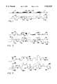
- FIG. 1is a diagrammatic representation of a first cycle of the etching process, illustrating a first surface having a maskant applied thereto and a second surface indicating the resultant surface after etching.
- FIG. 2is a diagrammatic representation of the second cycle of the etching process, illustrating the second surface illustrated in FIG. 1 having a maskant applied thereto and a resultant third surface prepared by etching the masked second surface.
- FIG. 3is a diagrammatic representation of the third cycle of the etching process illustrating the resultant third etched surface of FIG. 2, also having a maskant applied thereto and a fourth surface prepared by etching the masked surface.
- FIG. 4is a photomicrograph of the chemically etched surface.
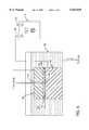
- FIG. 5is a diagrammatic representation, partially in cross section, of the arrangement of the elements of a typical electrochemical etching process.
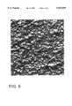
- FIG. 6is a photomicrograph of the electrochemically etched surface.
- the drawings and descriptionrefer to the use of a titanium alloy base metal. While titanium is the preferred embodiment for the implantable material, a number of other alloys may be utilized. Each of these different alloys will require a different maskant and etchant composition. Other than cobalt chromium, no specific details are given in the specification regarding the use of these other metals and etchants. It is, however, considered to be well within the knowledge of an experienced practitioner in the art to select an etchant once a base alloy has been identified. Furthermore, for the purposes of clarity, certain repetitive elements in the drawings have not been numerically identified for each and every occurrence.
- an unfinished surface 1is provided which diagrammatically represents the exterior surface of the device to be implanted.
- Unfinished surface 1 at level Ais generally smooth and comprised of titanium metal or alloy such as Ti-6Al-4Va. As stated herein, a cobalt chromium alloy is also contemplated.
- a maskantis applied to the surface of the implant which is to be etched in a random fashion. Several methods may be utilized to accomplish the random spattering of the maskant on the surface.
- the maskantmust be chosen carefully in order to provide a substance which will cling tightly to the surface of the implant during manipulation of the implant and will also remain stable when the etchant solution is applied to the coated part.
- the maskantmust also be removed with no residue once its function has been accomplished.
- a particular problem encountered when utilizing maskantsis the performance of the maskant at the boundaries of its application.
- the maskantshould produce a sharply defined edge once the etching process has begun and not itself deteriorate during the etching process. This might permit partial degradation of the substrate in a masked area. It should be noted, however, that some deterioration is found in any maskant use and does provide some of the particular surface features of the etched implant described later.
- the surface 1 of the implantmust be clean and grease-free and any oxidized material should be removed before the application of the maskant. This may be accomplished either mechanically, chemically or both.
- the surfacemay be cleaned mechanically utilizing a light abrasive blast of aluminum oxide particles or glass beads. Alternatively, blasting with any small solid particle which will not degrade the surface is contemplated.
- a chemical agentsuch as methanol may be utilized alone or in conjunction with the blasting.
- Most maskantsare very sensitive to the condition of the applied surface and both application and removal of the maskant may be affected by improper surface treatment.
- the maskantcan be comprised of a number of materials including neoprene elastomers and isobutylene isoprene copolymers.
- the particular maskantshould be selected based on the type of etchant utilized.
- the preferred maskantis AC-818C, an air-cured, general purpose, peelable coating produced by A.C. Products, Inc. of Placentia, Calif.
- the maskantis thinned utilizing perchlorethylene to 35-45 seconds utilizing a No. 5 Zahn cup.
- the maskantif too thin, may be thickened to this viscosity by evaporation of the carrier. While the maskant is traditionally utilized in the 14-18 second range, it has been found that this thicker version produces superior results in terms of applying the maskant utilizing manual daubing or spray application techniques.
- the maskantis applied in a random spattered fashion allowing only a portion of the surface of the implant to be coated thereby.
- a random "polka dot" patternis preferred in which each of the maskant points is of varying size and thickness when compared to the others.
- the applied maskantmay be partially abraded utilizing the grit blasting technique described previously for cleaning with an 80-120 mesh grit at 80-90 psi. to assist in providing an irregular maskant coating.
- FIG. 1a variety of applied maskant points 5 are illustrated. A particularly thick maskant agglomeration 10 is also illustrated. Other surface features of the applied maskant include an applied maskant plateau 15 and an applied maskant thin layer 20. It is desirable to achieve a variety of sizes and thicknesses of maskant in order to obtain the proper random finished surface. As will be seen later, each of these particular maskant surface features produces a somewhat different etched result. An optional step of drying the maskant at an elevated temperature is also contemplated. Four to five minutes at 200° F. is sufficient.
- the unfinished surface indication line 24, shown as a chain,indicates the original level identified by the letter A at which the surface began.
- the first etched surface 25 identified by the letter Bshows the resultant etched surface. While a number of etchants could be utilized, the particular chemistry adopted for the preferred embodiment utilizes a standard 30% nitric acid--6% hydrofluoric acid combination which is commonly marketed and well known in the art.
- the etchantis applied at 110° F. for approximately 4 minutes to achieve a desired 0.008-0.010 inch etch depth. This time period or the strength of the etchant solution may be adjusted upwardly or downwardly to achieve a heavier or lighter etching. The etching is halted in a water bath or spray.
- the maskant materialmay be removed in a variety of ways.
- the materialmay be removed mechanically or chemically. Depending on the size and number of coated objects, mechanical brushing or blasting of the maskant will peel it off. Additionally, the use of nitric acid is contemplated to dissolve the maskant material.
- a primary plateau 30corresponds to the applied maskant plateau 15 illustrated in the top drawing.
- the heavy maskant coatcompletely protects the implant surface, preventing any metallic material from being removed at this point.
- a secondary plateau 35corresponds to the thin layer 20 illustrated in the above drawing. The intermediate height of the secondary plateau between levels A and B indicates that the maskant performed for some period during the etching cycle but failed at an intermediate time allowing some of the alloy to be etched away.
- a small promontory, third from the left as shown in FIG. 1,also illustrates a small secondary plateau 35.
- Gradually sloped feature 40corresponds to a gradually tapering maskant coverage which partially protects the underlying substrate during the etching cycle.
- a highly sloped feature 44indicates a thicker maskant coating which enjoyed a highly defined perimeter before etching.
- a medium sloped feature 45indicates a maskant condition intermediate the two previously described. The extremes of the etching are indicated by unetched level 46 and first etched level 47 which illustrate the effect of complete maskant coating versus no maskant coating. It should be noted that the base of each surface feature provides full dimensionally filleted radii.
- FIG. 2also employs two illustrations to display the effects of a second masking/etching cycle.
- the upper illustrationcorresponds to the second illustration of FIG. 1, the lowest extreme being found at the level indicated as B.
- the maskantis again applied to a clean and prepared surface in a random fashion according to the same techniques described with reference to FIG. 1. As before, a randomized pattern is preferable in which a wide variety of maskant surface features is achieved.
- Second applied maskant points 50illustrate a variety of positions in which the maskant may be applied to the now irregular surface features of first etched surface 25.
- the first etched surface indication line 55is shown in chain line to indicate the previous surface prior to the second etching cycle.
- the second etching cycleis performed under identical conditions as that described with reference to FIG. 1 to again achieve a 0.008-0.010 inch maximum etch.
- Second etched surface 60is shown at level C, indicating a resultant etched surface.
- a highly sloped surface feature 44corresponds again to a sharply defined and relatively thick application of maskant while a gradually sloped surface feature 40 corresponds to a gradually thinning maskant application. This feature is particularly visible in the two illustrations contained in FIG. 2 in which the gradual thinning of the maskant application is particularly exaggerated.
- FIG. 2As can be seen in the second illustration of FIG. 2, three major levels of surface features are illustrated with a few intermediate features present to demonstrate the effects of partial maskant failure. A few points remain at unetched level 46 indicating maskant coverage during both etchant cycles. Some points are illustrated at first etched level 47 indicating maskant coverage during one of the two cycles, while points located at second etched level 75 have been exposed to the etchant during both of the etching cycles. The increasing level of complexity of surface forms is apparent with comparison between FIGS. 1 and 2.
- FIG. 3is essentially a repetition of FIG. 2 having an upper illustration showing the application of third applied maskant points 80 to the now highly featured second etched surface 60 at level C.
- the increasing complexity of the surface of the etched devicecontributes also to the complexity of the maskant forms when applied to the irregular surface.
- the second illustration of FIG. 3is shown to demonstrate the effect of a less rigorous etching cycle, being roughly one-half of the depth shown in FIGS. 1 and 2.
- the number and length of each etching cycleis purely dependent on the complexity of features required by the application and may be performed by any order.
- a gradually sloped surface feature 40retains its gradually sloped character from one cycle to the next when not covered by a maskant.
- Highly sloped surface feature 44again illustrates the effect of a highly stable maskant agglomeration while medium sloped surface feature 45 again demonstrates an intermediate condition.
- medium sloped surface feature 45again demonstrates an intermediate condition.
- four major surface levelsare illustrated. Points at unetched level 46 are still apparent although fewer in number and relatively rare. A number of plateaus remain at first etched level 47 and second etched level 75. Those areas which have been exposed during all three etchant cycles enjoy depressions at third etched surface 100 corresponding to level D in FIG. 3. These levels correspond to areas which have had coverage during all three cycles, two cycles, one cycle and no cycles, respectively.
- third etched surface 90is of a highly non-uniform featured surface which, compared with its length, also exhibits a large surface area.
- the different levels of depression and protrusionare particularly adapted to permit the ingrowth of bone and to allow for a firm anchoring of the bone along the surface of the implant structure.
- FIG. 4illustrates a sample resultant surface. While specific identification of the surface features is difficult, a long ridge line is visible extending diagonally from upper left to lower right. A first level of three plateaus is visible at the center of the Figure, and lower level features extend outwardly in the upper right and lower left directions. All surface features are fully filleted and irregularly shaped to promote bone ingrowth.
- an unfinished surface 1is provided which diagrammatically represents the exterior surface of a device, such as a bone implant, that is to be joined to a second material.
- the letter identifiers on the right margin of the drawingsare intended to provide a quick reference to the relative levels of electrochemical etching.
- Unfinished surface 1 at level Ais generally smooth and comprised of cobalt-chromium alloy such as the cobalt-28 chromium-6 molybdenum alloy described in Table 1.
- a maskantis applied to the surface of the device which is to be electrochemically etched in a random fashion. Several methods may be utilized to accomplish the random spattering of the maskant on the surface.
- the maskantmust be chosen carefully in order to provide a substance which will cling tightly to the surface of the device during manipulation of the device and will also remain stable when the etchant solution is applied to the coated part.
- the maskantmust also be removed with no residue once its function has been accomplished.
- a particular problem encountered when utilizing maskantsis the performance of the maskant at the boundaries of its application.
- the maskantshould produce a sharply defined edge once the electrochemical etching process has begun and not itself deteriorate during the electrochemical etching process. This might permit partial degradation of the substrate in a masked area. It should be noted, however, that some deterioration is found in any maskant use and does provide some of the particular surface features of the electrochemical etched device described later.
- the surface 1 of the devicemust be clean and grease-free and any oxidized material should be removed before the application of the maskant. This may be accomplished either mechanically, chemically or both.
- the surfacemay be cleaned mechanically utilizing a light abrasive blast of 80 to 120 grit aluminum oxide particles or glass beads. Alternatively, blasting with any small solid particle which will not degrade the surface is contemplated. All blasting residue is to be removed by brushing.
- a chemical agentsuch as acetone may be utilized alone or in conjunction with the blasting to clean the surface 1.
- Most maskantsare very sensitive to the condition of the applied surface and both application and removal of the maskant may be affected by improper surface treatment.
- the maskantcan be comprised of a number of materials including neoprene elastomers and isobutylene isoprene copolymers.
- the preferred maskant for use with cobalt-chromium alloysis an alkaline soluble, air-curable phenol-formaldehyde resin maskant material such as Hysol ER1006 produced by The Dexter Corporation, Industry, Calif.
- the maskantis applied in a random spattered fashion allowing only a portion of the surface of the device to be coated thereby.
- a random "polka dot" patternis preferred in which each of the maskant points is of varying size and thickness when compared to the others.
- the applied maskantmay be partially abraded utilizing the grit blasting technique described previously for cleaning with an 80-120 mesh grit at 80-90 psi to assist in providing an irregular maskant coating.
- the viscosity of the maskantshould be adjusted to a level that promotes both the application of the maskant in a random spattered pattern and the proper curing of the maskant.
- the maskantmay be thinned to the optimum viscosity by the addition of its carrier fluid. If the maskant is too thin, the maskant may be thickened to a lower viscosity by evaporation of its carrier fluid.
- the optimum viscosityis about 60-66 seconds as measured utilizing a No. 5 Zahn cup.
- the maskantAfter the maskant has been applied in a random spattered pattern, it is cured.
- the Hysol ER1006 maskantis preferably cured for a minimum of about 20 minutes at between about 200-250° F. and then air cooled to room temperature.
- FIG. 1a variety of applied maskant points 5 are illustrated. A particularly thick maskant agglomeration 10 is also illustrated. Other surface features of the applied maskant include an applied maskant plateau 15 and an applied maskant thin layer 20. It is desirable to achieve a variety of sizes and thicknesses of maskant in order to obtain the proper random finished surface. As will be seen later, each of these particular maskant surface features produces a somewhat different electrochemical etching result.
- FIG. 5diagrammically shows the arrangement of the elements of a typical electrochemical etching process.
- the exposed portion 120 of the attachment surface 108 of workpiece 110is ready to be electrochemically etched.
- the exposed portion 120 of the attachment surface 108is that portion of the attachment surface 108 which is not covered by maskant deposits 116.
- a tank 126may be used to submerge the tooling 106 and the workpiece 110 under an electrolyte fluid 102.
- the electrolyte fluid 102fills the work gap 104 between the tooling 106 and the attachment surface 108 of the workpiece 110.
- the electrolyte fluid 102is pumped at controlled rate through a passageway 114 in the tooling 106 and out through an orifice 118 into the work gap 104.
- the tooling 106is in electrical connection with the negative terminal 124 of a direct current power supply 112 and thus becomes the cathode of the electrochemical etching process.
- the workpiece 110is in electrical connection with the positive terminal 122 of the same direct current power supply 112 and thus becomes the anode of the electrochemical etching process.
- the electrolyte fluid 102 for electrochemically etching a cobalt-chromium alloyis preferably a solution containing the proportions of one pound each of NaCl and NaNO 3 dissolved in one gallon of water.
- electrochemically etching metalswill recognize and employ the appropriate electrolyte fluid 102 to be used for the type of metal of a particular workpiece 110.
- Control of the flow rate of the electrolyte fluid 102 through the work gap 104is important because the electrolyte fluid 104 must adequately remove both the heat and the reaction products of the electrochemical process.
- the optimum flow rate levelis related to the amount of current employed. Higher ratios of flow rate to current give better removal of heat and reaction products.
- the electrolyte fluid 102should flow through the work gap 104 at a rate of about 0.15-0.5 gallons per minute per 100 amps and have a temperature of between about 100-130° F.
- electrochemically etching metalswill be able to determine the proper values of these parameters to use with a particular application.
- the tooling 106may be made from any material suitable for use in electrochemical etching such as copper, nickel, or an alloy of tungsten-copper.
- the tooling 106should be configured so that the work gap 104 between the tooling 106 and the attachment surface 108 is substantially uniform. This is accomplished by making the tooling 106 substantially conformal to the attachment surface 108.
- the work gap 104is between about 0.020-0.250 inches, more particularly between about 0.060-0.120 inches.
- electrochemically etching metalwill be able to determine the proper work gap 104 to use for a particular application.
- a direct current voltage difference between the tooling 106 and the attachment surface 108 of between about 8V-24V and a specific amperage of at least about 50 amps per square inch of exposed portion 120 of the attachment surface 108are to be maintained during the electrochemical etching of a cobalt-chromium workpiece 110.
- the direct current voltage difference between the tooling 106 and the attachment surface 108is between about 12-18 V and the specific amperage is about 75-120 amps per square inch of exposed portion 120 of the attachment surface 108.
- the values of these parameters for use with other materialsare readily determinable by one skilled in the art of electrochemical etching metals. The stated conditions will produce a metal removal rate of about 0.003 inch per minute when the workpiece 110 material is a cobalt-chromium alloy.
- the electrochemically etched resultis illustrated, based on the applied maskant shown in the upper illustration.
- the unfinished surface indication line 24, shown as a chain,indicates the original level identified by the letter A at which the surface began.
- the first electrochemically etched surface 25 identified by the letter Bshows the resultant electrochemically etched surface.
- the electrochemical etchingis continued until a desired etch depth of about 0.001-0.010 inch is achieved. Preferably, the etching is continued until a desired etch depth of about 0.002-0.007 inches is achieved.
- the time period and other parameters of the electrochemical etching process, particular the specific amperage,may be adjusted upwardly or downwardly to achieve a heavier or lighter etching.
- the electrochemical etching processis halted by removing the voltage difference between the tooling 106 and the workpiece 110.
- the maskant material on the attachment surface 106is removed after each electrochemical etching step.
- the maskant materialmay be removed in a variety of ways.
- the maskant materialmay be removed mechanically or chemically. Depending on the size and number of coated objects, mechanical brushing or blasting of the maskant may peel it off.
- the workpieceis immersed in an aqueous solution of an alkaline cleaner to dissolve the maskant material.
- the temperature of the alkaline cleaner solutionis between about 80-145° F.
- the immersion timeis about 5 to 10 minutes or until the maskant is removed. Water blasting is employed to remove any clinging maskant material which was softened by the alkaline cleaning solution.
- the masking/electrochemical etching processis repeated three times, though useful attachment surfaces may be obtained through the use of fewer and more numerous cycles.
- the amount of material removed during each cycleis to be determined by the particular application.
- the attachment surface 106be blasted with 80 to 120 mesh alumina grit prior to the application of the maskant material so as to promote the adhesion of the maskant material.
- a primary plateau 30corresponds to the applied maskant plateau 15 illustrated in the top drawing.
- the heavy maskant coatcompletely protects the device surface, preventing any metallic material from being removed at this point.
- a secondary plateau 35corresponds to the thin layer 20 illustrated in the above drawing.
- the intermediate height of the secondary plateau between levels A and Bindicates that the maskant performed for some period during the electrochemical etching cycle but failed at an intermediate time allowing some of the alloy to be etched away.
- a small promontory, third from the left as shown in FIG. 1,also illustrates a small secondary plateau 35.
- Gradually sloped feature 40corresponds to a gradually tapering maskant coverage which partially protects the underlying substrate during the electrochemical etching cycle.
- a highly sloped feature 44indicates a thicker maskant coating which enjoyed a highly defined perimeter before the electrochemical etching.
- a medium sloped feature 45indicates a maskant condition intermediate the two previously described.
- the extremes of the electrochemical etchingare indicated by unetched level 46 and first electrochemically etched level 47 which illustrate the effect of complete maskant coating versus no maskant coating. It should be noted that the base of each surface feature provides full dimensionally filleted radii.
- FIG. 2also employs two illustrations to display the effects of a second masking/electrochemical etching cycle.
- the upper illustrationcorresponds to the second illustration of FIG. 1, the lowest extreme being found at the level indicated as B.
- the maskantis again applied to a clean and prepared surface in a random fashion according to the same techniques described with reference to FIG. 1. As before, a randomized pattern is preferable in which a wide variety of maskant surface features is achieved.
- Second applied maskant points 50illustrate a variety of positions in which the maskant may be applied to the now irregular surface features of first electrochemically etched surface 25.
- the first electrochemically etched surface indication line 55is shown in chain line to indicate the previous surface prior to the second electrochemical etching cycle.
- the second electrochemical etching cycleis performed under identical conditions as that described with reference to FIG. 1 to again achieve an approximately 0.001-0.010 inch electrochemical etch.
- Second electrochemically etched surface 60is shown at level C, indicating a resultant electrochemically etched surface.
- a highly sloped surface feature 44corresponds again to a sharply defined and relatively thick application of maskant while a gradually sloped surface feature 40 corresponds to a gradually thinning maskant application. This feature is particularly visible in the two illustrations contained in FIG. 2 in which the gradual thinning of the maskant application is particularly exaggerated.
- FIG. 2As can be seen in the second illustration of FIG. 2, three major levels of surface features are illustrated with a few intermediate features present to demonstrate the effects of partial maskant failure. A few points remain at unetched level 46 indicating maskant coverage during both electrochemical etching cycles. Some points are illustrated at first electrochemically etched level 47 indicating maskant coverage during one of the two cycles, while points located at second electrochemically etched level 75 have been exposed to the electrochemical etching process during both of the electrochemical etching cycles. The increasing level of complexity of surface forms is apparent with comparison between FIGS. 1 and 2.
- FIG. 3is essentially a repetition of FIG. 2 having an upper illustration showing the application of third applied maskant points 80 to the now highly featured second electrochemically etched surface 60 at level C.
- the increasing complexity of the surface of the electrochemically etched devicecontributes also to the complexity of the maskant forms when applied to the irregular surface.
- the second illustration of FIG. 3is shown to demonstrate the effect of a less intense electrochemical etching cycle, being roughly one-half of the depth shown in FIGS. 1 and 2.
- the number and intensity of each electrochemical etching cycleis dependent on the complexity of features required by the application and may be performed in any order.
- a gradually sloped surface feature 40retains its gradually sloped character from one cycle to the next when not covered by a maskant.
- Highly sloped surface feature 44again illustrates the effect of a highly stable maskant agglomeration while medium sloped surface feature 45 again demonstrates an intermediate condition.
- medium sloped surface feature 45again demonstrates an intermediate condition.
- four major surface levelsare illustrated. Points at unetched level 46 are still apparent although fewer in number and relatively rare. A number of plateaus remain at first electrochemically etched level 47 and second electrochemically etched level 75. Those areas which have been exposed during all three electrochemical etch process cycles enjoy depressions at third electrochemically etched surface 100 corresponding to level D in FIG. 3. These levels correspond to areas which have had coverage during all three cycles, two cycles, one cycle and no cycles, respectively.
- third electrochemically etched surface 90is a highly non-uniform featured surface which, compared with its length, also exhibits a large surface area.
- the different levels of depression and protrusionare particularly adapted to permit the ingrowth of bone and to allow for a firm anchoring of the bone along the surface of an implant structure.
- the different levels of depression and protrusionsare also particular adapted to permit the inflow and anchoring of adhesives.
- FIG. 6illustrates a sample resultant surface. All surface features are fully filleted and irregularly shaped to promote bone ingrowth and the inflow of adhesives.
Landscapes
- Health & Medical Sciences (AREA)
- Chemical & Material Sciences (AREA)
- Animal Behavior & Ethology (AREA)
- Veterinary Medicine (AREA)
- Oral & Maxillofacial Surgery (AREA)
- Transplantation (AREA)
- Engineering & Computer Science (AREA)
- Public Health (AREA)
- General Health & Medical Sciences (AREA)
- Life Sciences & Earth Sciences (AREA)
- Heart & Thoracic Surgery (AREA)
- Vascular Medicine (AREA)
- Biomedical Technology (AREA)
- Cardiology (AREA)
- Orthopedic Medicine & Surgery (AREA)
- Organic Chemistry (AREA)
- Metallurgy (AREA)
- Medicinal Chemistry (AREA)
- Epidemiology (AREA)
- Chemical Kinetics & Catalysis (AREA)
- General Chemical & Material Sciences (AREA)
- Materials Engineering (AREA)
- Mechanical Engineering (AREA)
- Dermatology (AREA)
- Inorganic Chemistry (AREA)
- ing And Chemical Polishing (AREA)
- Prostheses (AREA)
- Materials For Medical Uses (AREA)
Abstract
Description
TABLE 1______________________________________Composition of Cobalt-28 Chromium-6 Molybdenum Alloy minimum maximum tolerance +/- %* %* %*______________________________________Chromium 26.0 30.0 0.30Molybdenum 5 7 0.15Nickel -- 1.0 0.05Iron -- 0.75 0.03Carbon -- 0.35 0.02Silicon -- 1.0 0.05Manganese -- 1.0 0.03Nitrogen -- 0.25 0.03Cobalt balance -- --______________________________________ *weight percent.
Claims (33)
Priority Applications (9)
| Application Number | Priority Date | Filing Date | Title |
|---|---|---|---|
| US07/755,712US5258098A (en) | 1991-06-17 | 1991-09-06 | Method of production of a surface adapted to promote adhesion |
| US08/358,045US5507815A (en) | 1991-06-17 | 1994-12-15 | Random surface protrusions on an implantable device |
| US08/785,938US5922029A (en) | 1991-06-17 | 1997-01-22 | Surface for use on an implantable device and method of production therefor |
| US09/324,695US6193762B1 (en) | 1991-06-17 | 1999-06-02 | Surface for use on an implantable device |
| US10/339,816US6911249B2 (en) | 1991-06-17 | 2003-01-10 | Surface for use on implantable device |
| PCT/US2004/000488WO2004062477A2 (en) | 1991-06-17 | 2004-01-09 | Improved surface for use on implantable device |
| AU2004204772AAU2004204772B2 (en) | 1991-06-17 | 2004-01-09 | Improved surface for use on implantable device |
| CA002512954ACA2512954A1 (en) | 1991-06-17 | 2004-01-09 | Improved surface for use on implantable device |
| EP04701173AEP1583669A4 (en) | 1991-06-17 | 2004-01-09 | Improved surface for use on implantable device |
Applications Claiming Priority (7)
| Application Number | Priority Date | Filing Date | Title |
|---|---|---|---|
| US71616791A | 1991-06-17 | 1991-06-17 | |
| US07/755,712US5258098A (en) | 1991-06-17 | 1991-09-06 | Method of production of a surface adapted to promote adhesion |
| US12225493A | 1993-09-15 | 1993-09-15 | |
| US08/358,045US5507815A (en) | 1991-06-17 | 1994-12-15 | Random surface protrusions on an implantable device |
| US58879096A | 1996-01-19 | 1996-01-19 | |
| US08/785,938US5922029A (en) | 1991-06-17 | 1997-01-22 | Surface for use on an implantable device and method of production therefor |
| US10/339,816US6911249B2 (en) | 1991-06-17 | 2003-01-10 | Surface for use on implantable device |
Related Parent Applications (1)
| Application Number | Title | Priority Date | Filing Date |
|---|---|---|---|
| US58879096AContinuation-In-Part | 1991-06-17 | 1996-01-19 |
Publications (1)
| Publication Number | Publication Date |
|---|---|
| US5922029Atrue US5922029A (en) | 1999-07-13 |
Family
ID=35347046
Family Applications (5)
| Application Number | Title | Priority Date | Filing Date |
|---|---|---|---|
| US07/755,712Expired - LifetimeUS5258098A (en) | 1991-06-17 | 1991-09-06 | Method of production of a surface adapted to promote adhesion |
| US08/358,045Expired - LifetimeUS5507815A (en) | 1991-06-17 | 1994-12-15 | Random surface protrusions on an implantable device |
| US08/785,938Expired - LifetimeUS5922029A (en) | 1991-06-17 | 1997-01-22 | Surface for use on an implantable device and method of production therefor |
| US09/324,695Expired - Fee RelatedUS6193762B1 (en) | 1991-06-17 | 1999-06-02 | Surface for use on an implantable device |
| US10/339,816Expired - LifetimeUS6911249B2 (en) | 1991-06-17 | 2003-01-10 | Surface for use on implantable device |
Family Applications Before (2)
| Application Number | Title | Priority Date | Filing Date |
|---|---|---|---|
| US07/755,712Expired - LifetimeUS5258098A (en) | 1991-06-17 | 1991-09-06 | Method of production of a surface adapted to promote adhesion |
| US08/358,045Expired - LifetimeUS5507815A (en) | 1991-06-17 | 1994-12-15 | Random surface protrusions on an implantable device |
Family Applications After (2)
| Application Number | Title | Priority Date | Filing Date |
|---|---|---|---|
| US09/324,695Expired - Fee RelatedUS6193762B1 (en) | 1991-06-17 | 1999-06-02 | Surface for use on an implantable device |
| US10/339,816Expired - LifetimeUS6911249B2 (en) | 1991-06-17 | 2003-01-10 | Surface for use on implantable device |
Country Status (5)
| Country | Link |
|---|---|
| US (5) | US5258098A (en) |
| EP (1) | EP1583669A4 (en) |
| AU (1) | AU2004204772B2 (en) |
| CA (1) | CA2512954A1 (en) |
| WO (1) | WO2004062477A2 (en) |
Cited By (54)
| Publication number | Priority date | Publication date | Assignee | Title |
|---|---|---|---|---|
| EP1159935A1 (en)* | 2000-05-31 | 2001-12-05 | SAY, Wen-Ching | Orthopedic implant having a porous surface and method of making same |
| US20030065401A1 (en)* | 2001-01-25 | 2003-04-03 | Mark Amrich | Textured surface having undercut micro recesses in a surface |
| WO2003049781A1 (en) | 2001-12-06 | 2003-06-19 | Smith & Nephew, Inc. | In-situ oxidized textured surfaces for prosthetic devices and method of making same |
| WO2003059407A1 (en)* | 2002-01-21 | 2003-07-24 | Straumann Holding Ag | Surface-modified implants |
| US6599322B1 (en) | 2001-01-25 | 2003-07-29 | Tecomet, Inc. | Method for producing undercut micro recesses in a surface, a surgical implant made thereby, and method for fixing an implant to bone |
| US6620332B2 (en) | 2001-01-25 | 2003-09-16 | Tecomet, Inc. | Method for making a mesh-and-plate surgical implant |
| EP1358859A1 (en)* | 2002-04-29 | 2003-11-05 | Politecnico Di Milano | Bone prostheses having multilayer interface |
| US20030209517A1 (en)* | 2002-05-08 | 2003-11-13 | Mcgehee Brian | Post oxidation mass finishing techniques for prosthetic devices having textured diffusion-hardened surfaces |
| US20040002766A1 (en)* | 2002-06-27 | 2004-01-01 | Gordon Hunter | Prosthetic devices having diffusion-hardened surfaces and bioceramic coatings |
| US20040134886A1 (en)* | 1991-06-17 | 2004-07-15 | Wagner Donald J. | Surface for use on implantable device |
| EP1440669A1 (en)* | 2003-01-23 | 2004-07-28 | Dinkelacker, Wolfgang, Dr. med. dent. | Bone implant and process for its manufacture |
| WO2005009729A2 (en) | 2003-07-24 | 2005-02-03 | Tecomet, Inc. | Assembled non-random foams |
| US20060265065A1 (en)* | 2005-05-06 | 2006-11-23 | Bagga Charanpreet S | Anterior interbody spinal implant |
| US20080262623A1 (en)* | 2005-05-06 | 2008-10-23 | Titan Spine, Llc | Composite interbody spinal implant having openings of predetermined size and shape |
| US20100076559A1 (en)* | 2007-05-04 | 2010-03-25 | Titan Spine, Llc | Composite telescoping anterior interbody spinal implant |
| US20100074789A1 (en)* | 2008-09-25 | 2010-03-25 | Smith & Nephew Inc. | Medical implants having a porous coated suface |
| US20100217319A1 (en)* | 2009-02-24 | 2010-08-26 | Abbott Spine Inc. | System and method for spinal stabilization |
| EP2386274A1 (en) | 2010-05-14 | 2011-11-16 | Titan Spine, LLC | Interbody spinal implant having internally textured surfaces |
| EP2397110A1 (en) | 2003-06-25 | 2011-12-21 | BIEDERMANN MOTECH GmbH | Tissue integration design for seamless implant fixation |
| US8403991B2 (en) | 2005-05-06 | 2013-03-26 | Titan Spine Llc | Implant with critical ratio of load bearing surface area to central opening area |
| US8435302B2 (en) | 2005-05-06 | 2013-05-07 | Titan Spine, Llc | Instruments and interbody spinal implants enhancing disc space distraction |
| WO2013066376A1 (en) | 2011-11-01 | 2013-05-10 | Titan Spine, Llc | Microstructured implant surfaces |
| US8480749B2 (en) | 2005-05-06 | 2013-07-09 | Titan Spine, Llc | Friction fit and vertebral endplate-preserving spinal implant |
| WO2013142480A1 (en) | 2012-03-20 | 2013-09-26 | Titan Spine, Llc | Friction-fit spinal endplate and endplate-preserving method |
| US8545568B2 (en) | 2005-05-06 | 2013-10-01 | Titan Spine, Llc | Method of using instruments and interbody spinal implants to enhance distraction |
| US8551176B2 (en) | 2005-05-06 | 2013-10-08 | Titan Spine, Llc | Spinal implant having a passage for enhancing contact between bone graft material and cortical endplate bone |
| US8556987B2 (en) | 2004-09-16 | 2013-10-15 | Smith & Nephew, Inc. | Method of providing a zirconium surface and resulting product |
| US8562685B2 (en) | 2005-05-06 | 2013-10-22 | Titan Spine, Llc | Spinal implant and integration plate for optimizing vertebral endplate contact load-bearing edges |
| US8562684B2 (en) | 2005-05-06 | 2013-10-22 | Titan Spine, Llc | Endplate-preserving spinal implant with an integration plate having a roughened surface topography |
| US8585765B2 (en) | 2005-05-06 | 2013-11-19 | Titan Spine, Llc | Endplate-preserving spinal implant having a raised expulsion-resistant edge |
| US8585767B2 (en) | 2005-05-06 | 2013-11-19 | Titan Spine, Llc | Endplate-preserving spinal implant with an integration plate having durable connectors |
| US8585766B2 (en) | 2005-05-06 | 2013-11-19 | Titan Spine, Llc | Endplate-preserving spinal implant with an integration plate having durable connectors |
| US8591590B2 (en) | 2005-05-06 | 2013-11-26 | Titan Spine, Llc | Spinal implant having a transverse aperture |
| WO2013181234A1 (en) | 2012-05-31 | 2013-12-05 | Titan Spine, Llc | Endplate-preserving spinal implant with an integration plate having a roughened surface topography |
| US8617248B2 (en) | 2005-05-06 | 2013-12-31 | Titan Spine, Llc | Spinal implant having variable ratios of the integration surface area to the axial passage area |
| WO2014018325A1 (en) | 2012-07-25 | 2014-01-30 | Titan Spine, Llc | Implants having three distinct surfaces |
| EP2716261A1 (en) | 2012-10-02 | 2014-04-09 | Titan Spine, LLC | Implants with self-deploying anchors |
| EP2719360A1 (en) | 2012-10-09 | 2014-04-16 | Titan Spine, LLC | Expandable spinal implant with expansion wedge and anchor |
| US8758442B2 (en) | 2005-05-06 | 2014-06-24 | Titan Spine, Llc | Composite implants having integration surfaces composed of a regular repeating pattern |
| US8758443B2 (en) | 2005-05-06 | 2014-06-24 | Titan Spine, Llc | Implants with integration surfaces having regular repeating surface patterns |
| US8814939B2 (en) | 2005-05-06 | 2014-08-26 | Titan Spine, Llc | Implants having three distinct surfaces |
| EP2777725A2 (en) | 2013-03-14 | 2014-09-17 | Titan Spine, LLC | Surface and subsurface chemistry of an integration surface |
| US8992622B2 (en) | 2005-05-06 | 2015-03-31 | Titan Spine, Llc | Interbody spinal implant having a roughened surface topography |
| US9125756B2 (en) | 2005-05-06 | 2015-09-08 | Titan Spine, Llc | Processes for producing regular repeating patterns on surfaces of interbody devices |
| US9168147B2 (en) | 2005-05-06 | 2015-10-27 | Titan Spine, Llc | Self-deploying locking screw retention device |
| US9615935B2 (en) | 2014-01-30 | 2017-04-11 | Titan Spine, Llc | Thermally activated shape memory spring assemblies for implant expansion |
| US9655745B2 (en) | 2005-05-06 | 2017-05-23 | Titan Spine, Llc | Methods for manufacturing implants having integration surfaces |
| US10399166B2 (en) | 2015-10-30 | 2019-09-03 | General Electric Company | System and method for machining workpiece of lattice structure and article machined therefrom |
| WO2020124079A1 (en)* | 2018-12-14 | 2020-06-18 | Tech Met, Inc. | Cobalt chrome etching process |
| US10821000B2 (en) | 2016-08-03 | 2020-11-03 | Titan Spine, Inc. | Titanium implant surfaces free from alpha case and with enhanced osteoinduction |
| US11096796B2 (en) | 2005-05-06 | 2021-08-24 | Titan Spine, Llc | Interbody spinal implant having a roughened surface topography on one or more internal surfaces |
| US11370025B2 (en) | 2015-11-20 | 2022-06-28 | Titan Spine, Inc. | Processes for additively manufacturing orthopedic implants followed by eroding |
| US11510786B2 (en) | 2014-06-17 | 2022-11-29 | Titan Spine, Inc. | Corpectomy implants with roughened bioactive lateral surfaces |
| KR20220169580A (en)* | 2021-06-21 | 2022-12-28 | 주식회사 씨에스와이 | Etching method and apparatus of dental implant fixture |
Families Citing this family (133)
| Publication number | Priority date | Publication date | Assignee | Title |
|---|---|---|---|---|
| SE9202925D0 (en)* | 1992-10-07 | 1992-10-07 | Kabi Pharmacia Ab | METHOD IN THE PRODUCTION OF INTRAOCULAR LENSES |
| US5705082A (en)* | 1995-01-26 | 1998-01-06 | Chromalloy Gas Turbine Corporation | Roughening of metal surfaces |
| AU5095196A (en)* | 1995-03-17 | 1996-10-08 | Smith & Nephew Richards Inc. | Medical implants |
| AU6423796A (en)* | 1995-08-29 | 1997-03-06 | Johnson & Johnson Professional, Inc. | Bone prosthesis with protected coating for penetrating bone intergrowth |
| US6033582A (en)* | 1996-01-22 | 2000-03-07 | Etex Corporation | Surface modification of medical implants |
| US5843289A (en)* | 1996-01-22 | 1998-12-01 | Etex Corporation | Surface modification of medical implants |
| DE59707538D1 (en)* | 1996-04-10 | 2002-07-25 | Sulzer Orthopaedie Ag | Metal implant with a surface and method of making the surface |
| EP0800802B1 (en)* | 1996-04-10 | 2002-06-19 | Sulzer Orthopädie AG | Metallic implant having a surface and method of producing the surface |
| SE510025C2 (en)* | 1996-05-10 | 1999-04-12 | Robert J Medoff | Graft material retaining device |
| EP0827726A3 (en)* | 1996-09-04 | 1999-03-03 | Implantech Medizintechnik Ges.m.b.H. | Implant, especially prosthetic joint implant |
| AT405236B (en)* | 1997-07-18 | 1999-06-25 | Implantech Medizintechnik Ges | IMPLANT, IN PARTICULAR JOINT PROSTHESIS IMPLANT |
| US5716412A (en)* | 1996-09-30 | 1998-02-10 | Johnson & Johnson Professional, Inc. | Implantable article with ablated surface |
| US6141870A (en) | 1997-08-04 | 2000-11-07 | Peter K. Trzyna | Method for making electrical device |
| DE19813074A1 (en)* | 1998-03-25 | 1999-09-30 | Ceram Tec Ag Innovative Cerami | Clamp-fit connection between prosthetic components of joint prostheses |
| US7713297B2 (en) | 1998-04-11 | 2010-05-11 | Boston Scientific Scimed, Inc. | Drug-releasing stent with ceramic-containing layer |
| CH694935A5 (en)* | 2000-07-26 | 2005-09-30 | Straumann Holding Ag | Oberflaechenmodifizierte implants. |
| US6805898B1 (en)* | 2000-09-28 | 2004-10-19 | Advanced Cardiovascular Systems, Inc. | Surface features of an implantable medical device |
| WO2003002243A2 (en) | 2001-06-27 | 2003-01-09 | Remon Medical Technologies Ltd. | Method and device for electrochemical formation of therapeutic species in vivo |
| DE10142637B4 (en) | 2001-08-31 | 2009-07-09 | Disetronic Licensing Ag | Transcutaneous implant with surface structure and method for producing such an implant |
| EP1448908B1 (en)* | 2001-11-23 | 2006-02-01 | Universität Duisburg-Essen | Implant |
| AU2003206104A1 (en)* | 2002-01-24 | 2003-09-02 | Discure Ltd. | Joint prostheses |
| DE60310168T2 (en)* | 2002-08-02 | 2007-09-13 | Alstom Technology Ltd. | Method for protecting partial surfaces of a workpiece |
| EP1387040B1 (en)* | 2002-08-02 | 2006-12-06 | ALSTOM Technology Ltd | Method of protecting partial areas of a component |
| EP1411210A1 (en)* | 2002-10-15 | 2004-04-21 | ALSTOM Technology Ltd | Method of depositing an oxidation and fatigue resistant MCrAIY-coating |
| US20060147332A1 (en) | 2004-12-30 | 2006-07-06 | Howmedica Osteonics Corp. | Laser-produced porous structure |
| AU2003261497B2 (en) | 2002-11-08 | 2009-02-26 | Howmedica Osteonics Corp. | Laser-produced porous surface |
| US20040167632A1 (en)* | 2003-02-24 | 2004-08-26 | Depuy Products, Inc. | Metallic implants having roughened surfaces and methods for producing the same |
| US7074224B2 (en)* | 2003-06-25 | 2006-07-11 | Depuy Products, Inc. | Modular tapered reamer for bone preparation and associated method |
| US8998919B2 (en) | 2003-06-25 | 2015-04-07 | DePuy Synthes Products, LLC | Assembly tool for modular implants, kit and associated method |
| US20040267267A1 (en)* | 2003-06-25 | 2004-12-30 | Daniels David Wayne | Non-linear reamer for bone preparation and associated method |
| US7582092B2 (en) | 2003-06-25 | 2009-09-01 | Depuy Products, Inc. | Assembly tool for modular implants and associated method |
| US7297166B2 (en) | 2003-06-25 | 2007-11-20 | Depuy Products, Inc. | Assembly tool for modular implants and associated method |
| WO2005004941A1 (en)* | 2003-07-08 | 2005-01-20 | Poligrat Gmbh | Cementable endoprostheses |
| GB0325647D0 (en)* | 2003-11-03 | 2003-12-10 | Finsbury Dev Ltd | Prosthetic implant |
| US7588590B2 (en)* | 2003-12-10 | 2009-09-15 | Facet Solutions, Inc | Spinal facet implant with spherical implant apposition surface and bone bed and methods of use |
| US7785328B2 (en) | 2003-12-30 | 2010-08-31 | Depuy Products, Inc. | Minimally invasive bone miller apparatus |
| US8172904B2 (en)* | 2004-06-30 | 2012-05-08 | Synergy Disc Replacement, Inc. | Artificial spinal disc |
| US8337543B2 (en) | 2004-11-05 | 2012-12-25 | Boston Scientific Scimed, Inc. | Prosthesis anchoring and deploying device |
| SE529023C2 (en)* | 2005-06-17 | 2007-04-10 | Sandvik Intellectual Property | Coated carbide cutter |
| US7901462B2 (en)* | 2005-06-23 | 2011-03-08 | Depuy Products, Inc. | Implants with textured surface and methods for producing the same |
| US7268091B2 (en)* | 2005-08-19 | 2007-09-11 | Building Material Investment Corporation | Fiber mat and process for making same |
| CN101304813B (en)* | 2005-11-11 | 2011-08-17 | 日立化成研究中心公司 | Method of enhancing biocompatibility of elastomeric materials by microtexturing using microdroplet patterning |
| US8728387B2 (en) | 2005-12-06 | 2014-05-20 | Howmedica Osteonics Corp. | Laser-produced porous surface |
| US8840660B2 (en) | 2006-01-05 | 2014-09-23 | Boston Scientific Scimed, Inc. | Bioerodible endoprostheses and methods of making the same |
| US8089029B2 (en) | 2006-02-01 | 2012-01-03 | Boston Scientific Scimed, Inc. | Bioabsorbable metal medical device and method of manufacture |
| EP1826293A1 (en)* | 2006-02-09 | 2007-08-29 | Isoflux, Inc. | Formation of nanoscale surfaces for the attachment of biological materials |
| US20080299337A1 (en)* | 2006-02-09 | 2008-12-04 | Isoflux, Inc. | Method for the formation of surfaces on the inside of medical devices |
| US20070224235A1 (en) | 2006-03-24 | 2007-09-27 | Barron Tenney | Medical devices having nanoporous coatings for controlled therapeutic agent delivery |
| US8187620B2 (en) | 2006-03-27 | 2012-05-29 | Boston Scientific Scimed, Inc. | Medical devices comprising a porous metal oxide or metal material and a polymer coating for delivering therapeutic agents |
| US8048150B2 (en) | 2006-04-12 | 2011-11-01 | Boston Scientific Scimed, Inc. | Endoprosthesis having a fiber meshwork disposed thereon |
| US8815275B2 (en) | 2006-06-28 | 2014-08-26 | Boston Scientific Scimed, Inc. | Coatings for medical devices comprising a therapeutic agent and a metallic material |
| WO2008002778A2 (en) | 2006-06-29 | 2008-01-03 | Boston Scientific Limited | Medical devices with selective coating |
| EP2054537A2 (en) | 2006-08-02 | 2009-05-06 | Boston Scientific Scimed, Inc. | Endoprosthesis with three-dimensional disintegration control |
| EP2061629B1 (en) | 2006-09-11 | 2011-05-18 | Enbio Limited | Method of doping surfaces |
| EP2068757B1 (en) | 2006-09-14 | 2011-05-11 | Boston Scientific Limited | Medical devices with drug-eluting coating |
| WO2008034066A1 (en) | 2006-09-15 | 2008-03-20 | Boston Scientific Limited | Bioerodible endoprostheses and methods of making the same |
| ES2357661T3 (en) | 2006-09-15 | 2011-04-28 | Boston Scientific Scimed, Inc. | BIOEROSIONABLE ENDOPROOTHESIS WITH BIOESTABLE INORGANIC LAYERS. |
| EP2959925B1 (en) | 2006-09-15 | 2018-08-29 | Boston Scientific Limited | Medical devices and methods of making the same |
| JP2010503489A (en) | 2006-09-15 | 2010-02-04 | ボストン サイエンティフィック リミテッド | Biodegradable endoprosthesis and method for producing the same |
| WO2008036548A2 (en) | 2006-09-18 | 2008-03-27 | Boston Scientific Limited | Endoprostheses |
| US8597298B2 (en)* | 2006-09-29 | 2013-12-03 | DePuy Synthes Products, LLC | Proximal reamer |
| US7981150B2 (en) | 2006-11-09 | 2011-07-19 | Boston Scientific Scimed, Inc. | Endoprosthesis with coatings |
| NL1032851C2 (en)* | 2006-11-10 | 2008-05-14 | Fondel Finance B V | Kit and method for fixing a prosthesis or part thereof and / or filling bony defects. |
| WO2008082698A2 (en)* | 2006-12-28 | 2008-07-10 | Boston Scientific Limited | Medical devices and methods of making the same |
| ES2506144T3 (en) | 2006-12-28 | 2014-10-13 | Boston Scientific Limited | Bioerodible endoprosthesis and their manufacturing procedure |
| EP1961433A1 (en)* | 2007-02-20 | 2008-08-27 | National University of Ireland Galway | Porous substrates for implantation |
| US20080199720A1 (en)* | 2007-02-21 | 2008-08-21 | Depuy Products, Inc. | Porous metal foam structures and methods |
| US8431149B2 (en) | 2007-03-01 | 2013-04-30 | Boston Scientific Scimed, Inc. | Coated medical devices for abluminal drug delivery |
| US8070797B2 (en) | 2007-03-01 | 2011-12-06 | Boston Scientific Scimed, Inc. | Medical device with a porous surface for delivery of a therapeutic agent |
| US8067054B2 (en) | 2007-04-05 | 2011-11-29 | Boston Scientific Scimed, Inc. | Stents with ceramic drug reservoir layer and methods of making and using the same |
| US7976915B2 (en) | 2007-05-23 | 2011-07-12 | Boston Scientific Scimed, Inc. | Endoprosthesis with select ceramic morphology |
| US8066770B2 (en)* | 2007-05-31 | 2011-11-29 | Depuy Products, Inc. | Sintered coatings for implantable prostheses |
| ITBO20070436A1 (en)* | 2007-06-22 | 2008-12-23 | Azionaria Materiale Ospeda Lie | METHOD FOR PRODUCING SURFACES FOR METALLIC MANUALS |
| US20090008365A1 (en)* | 2007-07-06 | 2009-01-08 | Depuy Products, Inc. | Microtextured Implants and Methods of Making Same |
| US7942926B2 (en) | 2007-07-11 | 2011-05-17 | Boston Scientific Scimed, Inc. | Endoprosthesis coating |
| US8002823B2 (en) | 2007-07-11 | 2011-08-23 | Boston Scientific Scimed, Inc. | Endoprosthesis coating |
| EP2187988B1 (en) | 2007-07-19 | 2013-08-21 | Boston Scientific Limited | Endoprosthesis having a non-fouling surface |
| US7931683B2 (en) | 2007-07-27 | 2011-04-26 | Boston Scientific Scimed, Inc. | Articles having ceramic coated surfaces |
| US8815273B2 (en) | 2007-07-27 | 2014-08-26 | Boston Scientific Scimed, Inc. | Drug eluting medical devices having porous layers |
| WO2009018340A2 (en) | 2007-07-31 | 2009-02-05 | Boston Scientific Scimed, Inc. | Medical device coating by laser cladding |
| JP2010535541A (en) | 2007-08-03 | 2010-11-25 | ボストン サイエンティフィック リミテッド | Coating for medical devices with large surface area |
| US8052745B2 (en) | 2007-09-13 | 2011-11-08 | Boston Scientific Scimed, Inc. | Endoprosthesis |
| US8632600B2 (en) | 2007-09-25 | 2014-01-21 | Depuy (Ireland) | Prosthesis with modular extensions |
| US9204967B2 (en) | 2007-09-28 | 2015-12-08 | Depuy (Ireland) | Fixed-bearing knee prosthesis having interchangeable components |
| US8556912B2 (en) | 2007-10-30 | 2013-10-15 | DePuy Synthes Products, LLC | Taper disengagement tool |
| US8518050B2 (en) | 2007-10-31 | 2013-08-27 | DePuy Synthes Products, LLC | Modular taper assembly device |
| US8216632B2 (en) | 2007-11-02 | 2012-07-10 | Boston Scientific Scimed, Inc. | Endoprosthesis coating |
| US8029554B2 (en) | 2007-11-02 | 2011-10-04 | Boston Scientific Scimed, Inc. | Stent with embedded material |
| US7938855B2 (en) | 2007-11-02 | 2011-05-10 | Boston Scientific Scimed, Inc. | Deformable underlayer for stent |
| US20090204213A1 (en)* | 2008-02-13 | 2009-08-13 | Depuy Products, Inc. | Metallic implants |
| US20110104991A1 (en)* | 2008-03-12 | 2011-05-05 | Enbio Limited | Nozzle configurations for abrasive blasting |
| US20110081399A1 (en)* | 2008-03-13 | 2011-04-07 | Enbio Limited | Surface modification of nitinol |
| US8920491B2 (en) | 2008-04-22 | 2014-12-30 | Boston Scientific Scimed, Inc. | Medical devices having a coating of inorganic material |
| US8932346B2 (en) | 2008-04-24 | 2015-01-13 | Boston Scientific Scimed, Inc. | Medical devices having inorganic particle layers |
| US7998192B2 (en) | 2008-05-09 | 2011-08-16 | Boston Scientific Scimed, Inc. | Endoprostheses |
| US8236046B2 (en) | 2008-06-10 | 2012-08-07 | Boston Scientific Scimed, Inc. | Bioerodible endoprosthesis |
| EP2303350A2 (en) | 2008-06-18 | 2011-04-06 | Boston Scientific Scimed, Inc. | Endoprosthesis coating |
| US20090326674A1 (en)* | 2008-06-30 | 2009-12-31 | Depuy Products, Inc. | Open Celled Metal Implants With Roughened Surfaces and Method for Roughening Open Celled Metal Implants |
| US7985252B2 (en) | 2008-07-30 | 2011-07-26 | Boston Scientific Scimed, Inc. | Bioerodible endoprosthesis |
| US8167882B2 (en)* | 2008-09-30 | 2012-05-01 | Depuy Products, Inc. | Minimally invasive bone miller apparatus |
| US8382824B2 (en) | 2008-10-03 | 2013-02-26 | Boston Scientific Scimed, Inc. | Medical implant having NANO-crystal grains with barrier layers of metal nitrides or fluorides |
| US8231980B2 (en) | 2008-12-03 | 2012-07-31 | Boston Scientific Scimed, Inc. | Medical implants including iridium oxide |
| EP2403546A2 (en) | 2009-03-02 | 2012-01-11 | Boston Scientific Scimed, Inc. | Self-buffering medical implants |
| US8071156B2 (en) | 2009-03-04 | 2011-12-06 | Boston Scientific Scimed, Inc. | Endoprostheses |
| US8696759B2 (en)* | 2009-04-15 | 2014-04-15 | DePuy Synthes Products, LLC | Methods and devices for implants with calcium phosphate |
| US8287937B2 (en) | 2009-04-24 | 2012-10-16 | Boston Scientific Scimed, Inc. | Endoprosthese |
| GB0918484D0 (en)* | 2009-10-22 | 2009-12-09 | Depuy Int Ltd | A medical implant device |
| US8668732B2 (en) | 2010-03-23 | 2014-03-11 | Boston Scientific Scimed, Inc. | Surface treated bioerodible metal endoprostheses |
| US8533921B2 (en) | 2010-06-15 | 2013-09-17 | DePuy Synthes Products, LLC | Spiral assembly tool |
| WO2012012327A1 (en)* | 2010-07-20 | 2012-01-26 | X-Spine Systems, Inc. | Composite orthopedic implant having a low friction material substrate with primary frictional features and secondary frictional features |
| US9095452B2 (en) | 2010-09-01 | 2015-08-04 | DePuy Synthes Products, Inc. | Disassembly tool |
| ES2635496T3 (en) | 2011-04-06 | 2017-10-04 | Depuy Synthes Products Llc | Modular Orthopedic Hip Prosthesis |
| DE102011018677B4 (en)* | 2011-04-21 | 2014-11-20 | Zl Microdent-Attachment Gmbh & Co. Kg | Implant with a heterogeneously structured implant surface and method of manufacture |
| US9238093B2 (en)* | 2011-11-21 | 2016-01-19 | Medtronic, Inc | Surface improvement on electric discharge machined titanium alloy miniature parts for implantable medical device |
| US9135374B2 (en) | 2012-04-06 | 2015-09-15 | Howmedica Osteonics Corp. | Surface modified unit cell lattice structures for optimized secure freeform fabrication |
| US9180010B2 (en) | 2012-04-06 | 2015-11-10 | Howmedica Osteonics Corp. | Surface modified unit cell lattice structures for optimized secure freeform fabrication |
| US9250119B2 (en)* | 2012-06-01 | 2016-02-02 | The Governors Of The University Of Alberta | Apparatus and method for characterizing adhesive bonding and osseointegration |
| US9017055B2 (en) | 2012-07-12 | 2015-04-28 | Biomet Manufacturing, Llc | Device for coating intramedullary rods with cement |
| US9949837B2 (en) | 2013-03-07 | 2018-04-24 | Howmedica Osteonics Corp. | Partially porous bone implant keel |
| WO2015200266A1 (en)* | 2014-06-23 | 2015-12-30 | Community Blood Center | Cellular-scale surface modification for increased osteogenic protein expression |
| WO2016137983A1 (en) | 2015-02-24 | 2016-09-01 | X-Spine Systems, Inc. | Modular interspinous fixation system with threaded component |
| US10732085B2 (en)* | 2015-03-24 | 2020-08-04 | Bell Helicopter Textron Inc. | Notch treatment methods for flaw simulation |
| KR20160123075A (en)* | 2015-04-15 | 2016-10-25 | 오스템임플란트 주식회사 | Implant having a surface of micro-nano composite structure and method of surface-treating implant |
| US11376660B2 (en) | 2015-11-20 | 2022-07-05 | Titan Spine, Inc. | Processes for additively manufacturing orthopedic implants |
| US10070959B2 (en) | 2016-09-28 | 2018-09-11 | DePuy Synthes Products, Inc. | Method of texturing prosthetic implants |
| US11298747B2 (en) | 2017-05-18 | 2022-04-12 | Howmedica Osteonics Corp. | High fatigue strength porous structure |
| US10538686B2 (en) | 2017-09-27 | 2020-01-21 | Honda Motor Co., Ltd. | Multi-material assembly and methods of making thereof |
| US11065126B2 (en) | 2018-08-09 | 2021-07-20 | Stryker European Operations Holdings Llc | Interbody implants and optimization features thereof |
| US11851772B2 (en) | 2019-05-14 | 2023-12-26 | Tech Met, Inc. | Composition and method for creating nanoscale surface geometry on an implantable device |
| US11857436B1 (en) | 2019-07-31 | 2024-01-02 | Zavation Medical Products, Llc | Porous spinal implant |
| US11051953B2 (en) | 2019-07-31 | 2021-07-06 | Zavation Medical Products, Llc | Porous spinal implant |
| US11932947B2 (en) | 2019-08-29 | 2024-03-19 | Tech Met, Inc. | Composition and method for creating nanoscale surface geometry on a cobalt chromium implantable device |
| US11426904B2 (en) | 2020-09-11 | 2022-08-30 | Happe Spine Llc | Implantable medical device with varied composition and porosity, and method for forming same |
Citations (9)
| Publication number | Priority date | Publication date | Assignee | Title |
|---|---|---|---|---|
| US3793170A (en)* | 1971-06-09 | 1974-02-19 | Trw Inc | Electrochemical machining method and apparatus |
| US4006067A (en)* | 1973-03-05 | 1977-02-01 | Gussack Mark C | Oxidation-reduction process |
| US4173470A (en)* | 1977-11-09 | 1979-11-06 | Bell Telephone Laboratories, Incorporated | Novolak photoresist composition and preparation thereof |
| US4276132A (en)* | 1978-01-19 | 1981-06-30 | Shiley Incorporated | Electro-chemically machined ring and strut structure for prosthetic heart valves |
| US4432855A (en)* | 1982-09-30 | 1984-02-21 | International Business Machines Corporation | Automated system for laser mask definition for laser enhanced and conventional plating and etching |
| US4612101A (en)* | 1984-05-25 | 1986-09-16 | Aeg Elotherm Gmbh | Apparatus for the electrochemical etching of grooves of very small width |
| US5258098A (en)* | 1991-06-17 | 1993-11-02 | Cycam, Inc. | Method of production of a surface adapted to promote adhesion |
| US5516401A (en)* | 1993-07-08 | 1996-05-14 | Framatome | Process for electrochemical machining |
| US5549704A (en)* | 1994-09-08 | 1996-08-27 | Sutter; Franz | Universal joint prosthesis |
Family Cites Families (44)
| Publication number | Priority date | Publication date | Assignee | Title |
|---|---|---|---|---|
| US3073022A (en)* | 1959-04-03 | 1963-01-15 | Gen Motors Corp | Shot-peening treatments |
| GB1105388A (en)* | 1965-07-01 | 1968-03-06 | Imp Metal Ind Kynoch Ltd | Surface treatment of titanium |
| US3891456A (en)* | 1973-10-17 | 1975-06-24 | Us Air Force | Surface treatment of titanium and titanium alloys |
| US3995371A (en)* | 1974-10-10 | 1976-12-07 | The Curators Of The University Of Missouri | Electroless plating method for treating teeth |
| US4116755A (en)* | 1977-09-06 | 1978-09-26 | Mcdonnell Douglas Corporation | Chem-milling of titanium and refractory metals |
| CH630251A5 (en)* | 1978-05-19 | 1982-06-15 | Sulzer Ag | SURFACE STRUCTURE ON ANCHORING ELEMENT OF A BONE IMPLANT. |
| US4365359A (en)* | 1979-02-15 | 1982-12-28 | Raab S | PMMA Coated bone connective prostheses and method of forming same |
| SE416175B (en)* | 1979-03-07 | 1980-12-08 | Per Ingvar Branemark | FOR IMPLANTATION IN BODY TISSUE Separate Bone Tissue, Dedicated Material |
| US4314876A (en)* | 1980-03-17 | 1982-02-09 | The Diversey Corporation | Titanium etching solution |
| US4644942A (en)* | 1981-07-27 | 1987-02-24 | Battelle Development Corporation | Production of porous coating on a prosthesis |
| DE3133189C2 (en)* | 1981-08-21 | 1984-02-09 | MTU Motoren- und Turbinen-Union München GmbH, 8000 München | "Process for activating titanium surfaces" |
| US4834756A (en)* | 1982-02-18 | 1989-05-30 | Pfizer Hospital Products Group, Inc. | Bone prosthesis with porous coating |
| DE3321231C2 (en)* | 1983-06-11 | 1985-10-31 | MTU Motoren- und Turbinen-Union München GmbH, 8000 München | Process for the production of wear protection layers on the surfaces of components made of titanium or titanium-based alloys |
| US4673409A (en)* | 1984-04-25 | 1987-06-16 | Minnesota Mining And Manufacturing Company | Implant with attachment surface |
| US4540465A (en)* | 1984-06-11 | 1985-09-10 | Mcdonnell Douglas Corporation | Process for continuous recovery of nitric acid/hydrofluoric acid titanium etchant |
| US4863475A (en)* | 1984-08-31 | 1989-09-05 | Zimmer, Inc. | Implant and method for production thereof |
| US4634603A (en)* | 1985-04-22 | 1987-01-06 | United Technologies Corporation | Method of abrasive cleaning and spray coating |
| FR2590275B1 (en)* | 1985-11-19 | 1992-07-17 | Commissariat Energie Atomique | PROCESS FOR PREPARING THE SURFACE OF A PART MADE OF AN URANIUM AND TITANIUM ALLOY, IN PARTICULAR FOR CHEMICAL NICKELING |
| DD246028A1 (en)* | 1986-02-12 | 1987-05-27 | Karl Marx Stadt Tech Hochschul | CERAMIZED METAL IMPLANT |
| JPS63502405A (en)* | 1986-02-17 | 1988-09-14 | コモンウェルス・サイエンティフィック・アンド・インダストリアル・リサ−チ・オ−ガニゼ−ション | implantable material |
| US5002572A (en)* | 1986-09-11 | 1991-03-26 | Picha George J | Biological implant with textured surface |
| CA1269898A (en)* | 1986-10-17 | 1990-06-05 | Takayuki Shimamune | Process for production of calcium phosphate compound- coated composite material |
| US4865603A (en)* | 1988-02-04 | 1989-09-12 | Joint Medical Products Corporation | Metallic prosthetic devices having micro-textured outer surfaces |
| CH675826A5 (en)* | 1988-08-24 | 1990-11-15 | Sulzer Ag | |
| US4978358A (en)* | 1988-10-06 | 1990-12-18 | Zimmer Inc. | Orthopaedic prosthetic device possessing improved composite stem design |
| US5002580A (en)* | 1988-10-07 | 1991-03-26 | Pfizer Hospital Products Group, Inc. | Prosthetic device and method of implantation |
| US4955909A (en)* | 1989-01-31 | 1990-09-11 | Bioplasty, Inc. | Textured silicone implant prosthesis |
| EP0388576B1 (en)* | 1989-03-23 | 1993-09-15 | Institut Straumann Ag | Metallic implant |
| US4900398A (en)* | 1989-06-19 | 1990-02-13 | General Motors Corporation | Chemical milling of titanium |
| JPH03139821A (en)* | 1989-10-25 | 1991-06-14 | Toshiba Corp | How to form fine patterns |
| DE68927893T2 (en)* | 1989-12-01 | 1997-08-07 | Nissha Printing | ITEM PRODUCED IN A MOLD WITH A MATTE SURFACE AND MANUFACTURE THE SAME |
| US5057108A (en)* | 1990-01-12 | 1991-10-15 | Zimmer, Inc. | Method of surface finishing orthopedic implant devices |
| US5158571A (en)* | 1990-03-09 | 1992-10-27 | Picha George J | Tissue expander and method for expanding tissue |
| US5246530A (en)* | 1990-04-20 | 1993-09-21 | Dynamet Incorporated | Method of producing porous metal surface |
| US5211663A (en)* | 1991-06-24 | 1993-05-18 | Smith & Nephew Richards, Inc. | Passivation methods for metallic medical implants |
| US5411629A (en)* | 1992-02-03 | 1995-05-02 | Motorola, Inc. | Method for roughening surface of halocarbon film |
| US5307594A (en)* | 1992-12-14 | 1994-05-03 | Zimmer, Inc. | Method for forming textured surfaces on an orthopaedic implant |
| US5312520A (en)* | 1993-01-21 | 1994-05-17 | E-Systems, Inc. | Method of metallic surface preparation utilizing silane for adhesive bonding |
| US5673473A (en)* | 1993-06-25 | 1997-10-07 | Medtronic, Inc. | Method of surface finishing a medical device shield using metallic media |
| US5705082A (en)* | 1995-01-26 | 1998-01-06 | Chromalloy Gas Turbine Corporation | Roughening of metal surfaces |
| AU5095196A (en)* | 1995-03-17 | 1996-10-08 | Smith & Nephew Richards Inc. | Medical implants |
| DE59707538D1 (en)* | 1996-04-10 | 2002-07-25 | Sulzer Orthopaedie Ag | Metal implant with a surface and method of making the surface |
| US5853561A (en) | 1997-06-23 | 1998-12-29 | The United States Of America As Represented By The Administrator Of The National Aeronautics And Space Administration | Method for surface texturing titanium products |
| DE19814218A1 (en)* | 1998-03-31 | 1999-10-14 | Fuchs Fa Otto | Process for increasing the corrosion resistance of a metallic workpiece and workpiece |
- 1991
- 1991-09-06USUS07/755,712patent/US5258098A/ennot_activeExpired - Lifetime
- 1994
- 1994-12-15USUS08/358,045patent/US5507815A/ennot_activeExpired - Lifetime
- 1997
- 1997-01-22USUS08/785,938patent/US5922029A/ennot_activeExpired - Lifetime
- 1999
- 1999-06-02USUS09/324,695patent/US6193762B1/ennot_activeExpired - Fee Related
- 2003
- 2003-01-10USUS10/339,816patent/US6911249B2/ennot_activeExpired - Lifetime
- 2004
- 2004-01-09CACA002512954Apatent/CA2512954A1/ennot_activeAbandoned
- 2004-01-09AUAU2004204772Apatent/AU2004204772B2/ennot_activeCeased
- 2004-01-09WOPCT/US2004/000488patent/WO2004062477A2/enactiveIP Right Grant
- 2004-01-09EPEP04701173Apatent/EP1583669A4/ennot_activeWithdrawn
Patent Citations (9)
| Publication number | Priority date | Publication date | Assignee | Title |
|---|---|---|---|---|
| US3793170A (en)* | 1971-06-09 | 1974-02-19 | Trw Inc | Electrochemical machining method and apparatus |
| US4006067A (en)* | 1973-03-05 | 1977-02-01 | Gussack Mark C | Oxidation-reduction process |
| US4173470A (en)* | 1977-11-09 | 1979-11-06 | Bell Telephone Laboratories, Incorporated | Novolak photoresist composition and preparation thereof |
| US4276132A (en)* | 1978-01-19 | 1981-06-30 | Shiley Incorporated | Electro-chemically machined ring and strut structure for prosthetic heart valves |
| US4432855A (en)* | 1982-09-30 | 1984-02-21 | International Business Machines Corporation | Automated system for laser mask definition for laser enhanced and conventional plating and etching |
| US4612101A (en)* | 1984-05-25 | 1986-09-16 | Aeg Elotherm Gmbh | Apparatus for the electrochemical etching of grooves of very small width |
| US5258098A (en)* | 1991-06-17 | 1993-11-02 | Cycam, Inc. | Method of production of a surface adapted to promote adhesion |
| US5516401A (en)* | 1993-07-08 | 1996-05-14 | Framatome | Process for electrochemical machining |
| US5549704A (en)* | 1994-09-08 | 1996-08-27 | Sutter; Franz | Universal joint prosthesis |
Cited By (93)
| Publication number | Priority date | Publication date | Assignee | Title |
|---|---|---|---|---|
| US6911249B2 (en) | 1991-06-17 | 2005-06-28 | Medsource Technologies Pittsburgh, Inc. | Surface for use on implantable device |
| US20040134886A1 (en)* | 1991-06-17 | 2004-07-15 | Wagner Donald J. | Surface for use on implantable device |
| EP1159935A1 (en)* | 2000-05-31 | 2001-12-05 | SAY, Wen-Ching | Orthopedic implant having a porous surface and method of making same |
| US20060129161A1 (en)* | 2001-01-25 | 2006-06-15 | Tecomet, Inc. | Textured surface having undercut micro recesses in a surface |
| US7850862B2 (en) | 2001-01-25 | 2010-12-14 | Tecomet Inc. | Textured surface having undercut micro recesses in a surface |
| US6599322B1 (en) | 2001-01-25 | 2003-07-29 | Tecomet, Inc. | Method for producing undercut micro recesses in a surface, a surgical implant made thereby, and method for fixing an implant to bone |
| US6620332B2 (en) | 2001-01-25 | 2003-09-16 | Tecomet, Inc. | Method for making a mesh-and-plate surgical implant |
| US20030178387A1 (en)* | 2001-01-25 | 2003-09-25 | Mark Amrich | Method for making a mesh-and-plate surgical implant |
| US20030194869A1 (en)* | 2001-01-25 | 2003-10-16 | Amrich Mark P. | Method for producing undercut micro recesses in a surface, a surgical implant made thereby, and method for fixing an implant to bone |
| US20030065401A1 (en)* | 2001-01-25 | 2003-04-03 | Mark Amrich | Textured surface having undercut micro recesses in a surface |
| US7018418B2 (en) | 2001-01-25 | 2006-03-28 | Tecomet, Inc. | Textured surface having undercut micro recesses in a surface |
| WO2003049781A1 (en) | 2001-12-06 | 2003-06-19 | Smith & Nephew, Inc. | In-situ oxidized textured surfaces for prosthetic devices and method of making same |
| US7258810B2 (en) | 2001-12-06 | 2007-08-21 | Smith & Nephew, Inc. | In-situ oxidized textured surfaces for prosthetic devices and method of making same |
| US20030125808A1 (en)* | 2001-12-06 | 2003-07-03 | Gordon Hunter | In-situ oxidized textured surfaces for prosthetic devices and method of making same |
| CH695985A5 (en)* | 2002-01-21 | 2006-11-15 | Straumann Holding Ag | Surface-modified implants. |
| US20050064007A1 (en)* | 2002-01-21 | 2005-03-24 | Steinemann Samuel G. | Surface-modified implants |
| WO2003059407A1 (en)* | 2002-01-21 | 2003-07-24 | Straumann Holding Ag | Surface-modified implants |
| GB2401074B (en)* | 2002-01-21 | 2006-02-22 | Straumann Holding Ag | Surface-modified implants |
| GB2401074A (en)* | 2002-01-21 | 2004-11-03 | Straumann Holding Ag | Surface-modified implants |
| US20060089722A1 (en)* | 2002-04-29 | 2006-04-27 | Montevecchi Franco M | Bone prosthesis with multilayer interface |
| WO2003092555A1 (en)* | 2002-04-29 | 2003-11-13 | Franco Maria Montevecchi | Bone prosthesis with multilayer interface |
| EP1358859A1 (en)* | 2002-04-29 | 2003-11-05 | Politecnico Di Milano | Bone prostheses having multilayer interface |
| US20030209517A1 (en)* | 2002-05-08 | 2003-11-13 | Mcgehee Brian | Post oxidation mass finishing techniques for prosthetic devices having textured diffusion-hardened surfaces |
| WO2003094986A1 (en)* | 2002-05-08 | 2003-11-20 | Smith & Nephew, Inc. | Masking diffusion-hardened surfaces on prosthetic devices during post-oxidation mass finishing |
| US20040002766A1 (en)* | 2002-06-27 | 2004-01-01 | Gordon Hunter | Prosthetic devices having diffusion-hardened surfaces and bioceramic coatings |
| EP1440669A1 (en)* | 2003-01-23 | 2004-07-28 | Dinkelacker, Wolfgang, Dr. med. dent. | Bone implant and process for its manufacture |
| US20040153154A1 (en)* | 2003-01-23 | 2004-08-05 | Wolfgang Dinkelacker | Bone implant and method for manufacturing same |
| EP2397110A1 (en) | 2003-06-25 | 2011-12-21 | BIEDERMANN MOTECH GmbH | Tissue integration design for seamless implant fixation |
| US20050112397A1 (en)* | 2003-07-24 | 2005-05-26 | Rolfe Jonathan L. | Assembled non-random foams |
| US7208222B2 (en) | 2003-07-24 | 2007-04-24 | Viasys Healthcare Inc. | Assembled non-random foams |
| WO2005009729A2 (en) | 2003-07-24 | 2005-02-03 | Tecomet, Inc. | Assembled non-random foams |
| US9764061B2 (en) | 2004-09-16 | 2017-09-19 | Smith & Nephew, Inc. | Method of providing a zirconium surface and resulting product |
| US8556987B2 (en) | 2004-09-16 | 2013-10-15 | Smith & Nephew, Inc. | Method of providing a zirconium surface and resulting product |
| US8545568B2 (en) | 2005-05-06 | 2013-10-01 | Titan Spine, Llc | Method of using instruments and interbody spinal implants to enhance distraction |
| US8758443B2 (en) | 2005-05-06 | 2014-06-24 | Titan Spine, Llc | Implants with integration surfaces having regular repeating surface patterns |
| US11096796B2 (en) | 2005-05-06 | 2021-08-24 | Titan Spine, Llc | Interbody spinal implant having a roughened surface topography on one or more internal surfaces |
| US20060265065A1 (en)* | 2005-05-06 | 2006-11-23 | Bagga Charanpreet S | Anterior interbody spinal implant |
| US9655745B2 (en) | 2005-05-06 | 2017-05-23 | Titan Spine, Llc | Methods for manufacturing implants having integration surfaces |
| US7662186B2 (en)* | 2005-05-06 | 2010-02-16 | Titan Spine, Llc | Anterior interbody spinal implant |
| US8262737B2 (en) | 2005-05-06 | 2012-09-11 | Titan Spine, Llc | Composite interbody spinal implant having openings of predetermined size and shape |
| US9433511B2 (en) | 2005-05-06 | 2016-09-06 | Titan Spine, Llc | Interbody spinal implant having a roughened surface topography |
| US8403991B2 (en) | 2005-05-06 | 2013-03-26 | Titan Spine Llc | Implant with critical ratio of load bearing surface area to central opening area |
| US8435302B2 (en) | 2005-05-06 | 2013-05-07 | Titan Spine, Llc | Instruments and interbody spinal implants enhancing disc space distraction |
| US9327051B2 (en) | 2005-05-06 | 2016-05-03 | Titan Spine, Llc | Implants with integration surfaces having regular repeating surface patterns |
| US8480749B2 (en) | 2005-05-06 | 2013-07-09 | Titan Spine, Llc | Friction fit and vertebral endplate-preserving spinal implant |
| US8496710B2 (en) | 2005-05-06 | 2013-07-30 | Titan Spine, Llc | Interbody spinal implant having a roughened surface topography |
| US9168147B2 (en) | 2005-05-06 | 2015-10-27 | Titan Spine, Llc | Self-deploying locking screw retention device |
| US20080262623A1 (en)* | 2005-05-06 | 2008-10-23 | Titan Spine, Llc | Composite interbody spinal implant having openings of predetermined size and shape |
| US8551176B2 (en) | 2005-05-06 | 2013-10-08 | Titan Spine, Llc | Spinal implant having a passage for enhancing contact between bone graft material and cortical endplate bone |
| WO2006121795A3 (en)* | 2005-05-06 | 2007-11-29 | Titan Spine Llc | Anterior interbody spinal implant |
| US8562685B2 (en) | 2005-05-06 | 2013-10-22 | Titan Spine, Llc | Spinal implant and integration plate for optimizing vertebral endplate contact load-bearing edges |
| US8562684B2 (en) | 2005-05-06 | 2013-10-22 | Titan Spine, Llc | Endplate-preserving spinal implant with an integration plate having a roughened surface topography |
| US8585765B2 (en) | 2005-05-06 | 2013-11-19 | Titan Spine, Llc | Endplate-preserving spinal implant having a raised expulsion-resistant edge |
| US8585767B2 (en) | 2005-05-06 | 2013-11-19 | Titan Spine, Llc | Endplate-preserving spinal implant with an integration plate having durable connectors |
| US8585766B2 (en) | 2005-05-06 | 2013-11-19 | Titan Spine, Llc | Endplate-preserving spinal implant with an integration plate having durable connectors |
| US8591590B2 (en) | 2005-05-06 | 2013-11-26 | Titan Spine, Llc | Spinal implant having a transverse aperture |
| US9125756B2 (en) | 2005-05-06 | 2015-09-08 | Titan Spine, Llc | Processes for producing regular repeating patterns on surfaces of interbody devices |
| US8617248B2 (en) | 2005-05-06 | 2013-12-31 | Titan Spine, Llc | Spinal implant having variable ratios of the integration surface area to the axial passage area |
| US9011546B2 (en) | 2005-05-06 | 2015-04-21 | Titan Spine, Llc | Composite implants having integration surfaces composed of a regular repeating pattern |
| US8992622B2 (en) | 2005-05-06 | 2015-03-31 | Titan Spine, Llc | Interbody spinal implant having a roughened surface topography |
| US8940053B2 (en) | 2005-05-06 | 2015-01-27 | Titan Spine, Llc | Spinal implant and integration plate for optimizing vertebral endplate contact load-bearing edges |
| US8758442B2 (en) | 2005-05-06 | 2014-06-24 | Titan Spine, Llc | Composite implants having integration surfaces composed of a regular repeating pattern |
| US8834571B2 (en) | 2005-05-06 | 2014-09-16 | Titan Spine, Llc | Interbody spinal implant having a roughened surface topography |
| US8814939B2 (en) | 2005-05-06 | 2014-08-26 | Titan Spine, Llc | Implants having three distinct surfaces |
| US20100076559A1 (en)* | 2007-05-04 | 2010-03-25 | Titan Spine, Llc | Composite telescoping anterior interbody spinal implant |
| US8361381B2 (en) | 2008-09-25 | 2013-01-29 | Smith & Nephew, Inc. | Medical implants having a porous coated surface |
| US20100074789A1 (en)* | 2008-09-25 | 2010-03-25 | Smith & Nephew Inc. | Medical implants having a porous coated suface |
| US20100217319A1 (en)* | 2009-02-24 | 2010-08-26 | Abbott Spine Inc. | System and method for spinal stabilization |
| EP2386274A1 (en) | 2010-05-14 | 2011-11-16 | Titan Spine, LLC | Interbody spinal implant having internally textured surfaces |
| US8992619B2 (en) | 2011-11-01 | 2015-03-31 | Titan Spine, Llc | Microstructured implant surfaces |
| EP4129240A1 (en) | 2011-11-01 | 2023-02-08 | Titan Spine, Inc. | Microstructured implant surfaces |
| WO2013066376A1 (en) | 2011-11-01 | 2013-05-10 | Titan Spine, Llc | Microstructured implant surfaces |
| EP3718513A1 (en) | 2011-11-01 | 2020-10-07 | Titan Spine, Inc. | Microstructured implant surfaces |
| WO2013142480A1 (en) | 2012-03-20 | 2013-09-26 | Titan Spine, Llc | Friction-fit spinal endplate and endplate-preserving method |
| US9848995B2 (en) | 2012-03-20 | 2017-12-26 | Titan Spine Llc | Process for fabricating bioactive vertebral endplate bone-contacting surfaces on a spinal implant |
| WO2013181234A1 (en) | 2012-05-31 | 2013-12-05 | Titan Spine, Llc | Endplate-preserving spinal implant with an integration plate having a roughened surface topography |
| WO2014018325A1 (en) | 2012-07-25 | 2014-01-30 | Titan Spine, Llc | Implants having three distinct surfaces |
| EP2716261A1 (en) | 2012-10-02 | 2014-04-09 | Titan Spine, LLC | Implants with self-deploying anchors |
| US9642721B2 (en) | 2012-10-02 | 2017-05-09 | Titan Spine, Llc | Implants with self-deploying anchors |
| EP2719360A1 (en) | 2012-10-09 | 2014-04-16 | Titan Spine, LLC | Expandable spinal implant with expansion wedge and anchor |
| US9498349B2 (en) | 2012-10-09 | 2016-11-22 | Titan Spine, Llc | Expandable spinal implant with expansion wedge and anchor |
| EP2777725A2 (en) | 2013-03-14 | 2014-09-17 | Titan Spine, LLC | Surface and subsurface chemistry of an integration surface |
| US9615935B2 (en) | 2014-01-30 | 2017-04-11 | Titan Spine, Llc | Thermally activated shape memory spring assemblies for implant expansion |
| US11510786B2 (en) | 2014-06-17 | 2022-11-29 | Titan Spine, Inc. | Corpectomy implants with roughened bioactive lateral surfaces |
| US10399166B2 (en) | 2015-10-30 | 2019-09-03 | General Electric Company | System and method for machining workpiece of lattice structure and article machined therefrom |
| US11370025B2 (en) | 2015-11-20 | 2022-06-28 | Titan Spine, Inc. | Processes for additively manufacturing orthopedic implants followed by eroding |
| US10821000B2 (en) | 2016-08-03 | 2020-11-03 | Titan Spine, Inc. | Titanium implant surfaces free from alpha case and with enhanced osteoinduction |
| US11690723B2 (en) | 2016-08-03 | 2023-07-04 | Titan Spine, Inc. | Implant surfaces that enhance osteoinduction |
| US11712339B2 (en) | 2016-08-03 | 2023-08-01 | Titan Spine, Inc. | Titanium implant surfaces free from alpha case and with enhanced osteoinduction |
| US11053595B2 (en) | 2018-12-14 | 2021-07-06 | Tech Met, Inc. | Cobalt chrome etching process |
| JP2022513244A (en)* | 2018-12-14 | 2022-02-07 | テック メット インコーポレイテッド | Cobalt chrome etching method |
| WO2020124079A1 (en)* | 2018-12-14 | 2020-06-18 | Tech Met, Inc. | Cobalt chrome etching process |
| KR20220169580A (en)* | 2021-06-21 | 2022-12-28 | 주식회사 씨에스와이 | Etching method and apparatus of dental implant fixture |
Also Published As
| Publication number | Publication date |
|---|---|
| WO2004062477A2 (en) | 2004-07-29 |
| US5507815A (en) | 1996-04-16 |
| US6911249B2 (en) | 2005-06-28 |
| WO2004062477A3 (en) | 2007-08-09 |
| US20040134886A1 (en) | 2004-07-15 |
| CA2512954A1 (en) | 2004-07-29 |
| AU2004204772B2 (en) | 2007-05-17 |
| AU2004204772A1 (en) | 2004-07-29 |
| US6193762B1 (en) | 2001-02-27 |
| EP1583669A4 (en) | 2010-03-24 |
| EP1583669A2 (en) | 2005-10-12 |
| US5258098A (en) | 1993-11-02 |
Similar Documents
| Publication | Publication Date | Title |
|---|---|---|
| US5922029A (en) | Surface for use on an implantable device and method of production therefor | |
| US11015253B2 (en) | Surface treatment process for implants made of titanium alloy | |
| JP5079208B2 (en) | Metal implant having a rough surface and method for manufacturing the same | |
| EP1453554B1 (en) | In situ oxidized textured surfaces for prosthetic devices and method of making same | |
| JP3047373B2 (en) | Metal implant | |
| US20040167632A1 (en) | Metallic implants having roughened surfaces and methods for producing the same | |
| JP4444587B2 (en) | Method for attaching a porous metal layer to a metal substrate | |
| US20040153154A1 (en) | Bone implant and method for manufacturing same | |
| JPH08508654A (en) | Cleaning of porous and roughened surfaces of medical implants | |
| US5853561A (en) | Method for surface texturing titanium products | |
| NZ541649A (en) | Substrate material with irregular surface for use on implant device, formed by masking with random pattern, then blasting | |
| JPH02274893A (en) | Structure for plating and brazing shape-memory alloy and production of the same |
Legal Events
| Date | Code | Title | Description |
|---|---|---|---|
| AS | Assignment | Owner name:TECH MET, INCORPORATED, PENNSYLVANIA Free format text:ASSIGNMENT OF ASSIGNORS INTEREST;ASSIGNORS:WAGNER, DONALD J.;REED, GARY;REEL/FRAME:008538/0861 Effective date:19970226 Owner name:CYCAM, INC., PENNSYLVANIA Free format text:ASSIGNMENT OF ASSIGNORS INTEREST;ASSIGNORS:WAGNER, DONALD J.;REED, GARY;REEL/FRAME:008538/0861 Effective date:19970226 | |
| STCF | Information on status: patent grant | Free format text:PATENTED CASE | |
| CC | Certificate of correction | ||
| AS | Assignment | Owner name:WACHOVIA BANK, NA, AS ADMINISTRATIVE AGENT, NORTH Free format text:SECURITY INTEREST;ASSIGNOR:CYCAM, INC.;REEL/FRAME:013305/0064 Effective date:20020402 | |
| FPAY | Fee payment | Year of fee payment:4 | |
| AS | Assignment | Owner name:CREDIT SUISSE FIRST BOSTON, ACTING THROUGH ITS CAY Free format text:SECURITY AGREEMENT;ASSIGNOR:CYCAM, INC.;REEL/FRAME:015056/0580 Effective date:20040630 | |
| AS | Assignment | Owner name:ACCELLENT CORP., MASSACHUSETTS Free format text:RELEASE OF PATENT SECURITY AGREEMENT;ASSIGNOR:CREDIT SUISSE, CAYMAN ISLANDS BRANCH, (FORMERLY KNOWN AS CREDIT SUISSE FIRST BOSTON, ACTING THROUGH ITS CAYMAN ISLANDS BRANCH) AS COLLATERAL AGENT;REEL/FRAME:017125/0505 Effective date:20051122 Owner name:MEDICAL DEVICE MANUFACTURING, INC., MASSACHUSETTS Free format text:RELEASE OF PATENT SECURITY AGREEMENT;ASSIGNOR:CREDIT SUISSE, CAYMAN ISLANDS BRANCH, (FORMERLY KNOWN AS CREDIT SUISSE FIRST BOSTON, ACTING THROUGH ITS CAYMAN ISLANDS BRANCH) AS COLLATERAL AGENT;REEL/FRAME:017125/0505 Effective date:20051122 Owner name:UTI CORPORATION, MASSACHUSETTS Free format text:RELEASE OF PATENT SECURITY AGREEMENT;ASSIGNOR:CREDIT SUISSE, CAYMAN ISLANDS BRANCH, (FORMERLY KNOWN AS CREDIT SUISSE FIRST BOSTON, ACTING THROUGH ITS CAYMAN ISLANDS BRANCH) AS COLLATERAL AGENT;REEL/FRAME:017125/0505 Effective date:20051122 Owner name:MEDSOURCE TRENTON, INC., MASSACHUSETTS Free format text:RELEASE OF PATENT SECURITY AGREEMENT;ASSIGNOR:CREDIT SUISSE, CAYMAN ISLANDS BRANCH, (FORMERLY KNOWN AS CREDIT SUISSE FIRST BOSTON, ACTING THROUGH ITS CAYMAN ISLANDS BRANCH) AS COLLATERAL AGENT;REEL/FRAME:017125/0505 Effective date:20051122 Owner name:SPECTRUM MANUFACTURING, INC., MASSACHUSETTS Free format text:RELEASE OF PATENT SECURITY AGREEMENT;ASSIGNOR:CREDIT SUISSE, CAYMAN ISLANDS BRANCH, (FORMERLY KNOWN AS CREDIT SUISSE FIRST BOSTON, ACTING THROUGH ITS CAYMAN ISLANDS BRANCH) AS COLLATERAL AGENT;REEL/FRAME:017125/0505 Effective date:20051122 Owner name:NOBLE-MET, LTD., MASSACHUSETTS Free format text:RELEASE OF PATENT SECURITY AGREEMENT;ASSIGNOR:CREDIT SUISSE, CAYMAN ISLANDS BRANCH, (FORMERLY KNOWN AS CREDIT SUISSE FIRST BOSTON, ACTING THROUGH ITS CAYMAN ISLANDS BRANCH) AS COLLATERAL AGENT;REEL/FRAME:017125/0505 Effective date:20051122 Owner name:CYCAM, INC., MASSACHUSETTS Free format text:RELEASE OF PATENT SECURITY AGREEMENT;ASSIGNOR:CREDIT SUISSE, CAYMAN ISLANDS BRANCH, (FORMERLY KNOWN AS CREDIT SUISSE FIRST BOSTON, ACTING THROUGH ITS CAYMAN ISLANDS BRANCH) AS COLLATERAL AGENT;REEL/FRAME:017125/0505 Effective date:20051122 Owner name:MEDSOURCE TECHNOLOGIES, INC., MASSACHUSETTS Free format text:RELEASE OF PATENT SECURITY AGREEMENT;ASSIGNOR:CREDIT SUISSE, CAYMAN ISLANDS BRANCH, (FORMERLY KNOWN AS CREDIT SUISSE FIRST BOSTON, ACTING THROUGH ITS CAYMAN ISLANDS BRANCH) AS COLLATERAL AGENT;REEL/FRAME:017125/0505 Effective date:20051122 | |
| AS | Assignment | Owner name:JPMORGAN CHASE BANK N.A., AS ADMINISTRATIVE AGENT, Free format text:GRANT OF SECURITY INTEREST IN PATENTS;ASSIGNOR:CYCAM, INC.;REEL/FRAME:017136/0199 Effective date:20051122 | |
| FEPP | Fee payment procedure | Free format text:PAYOR NUMBER ASSIGNED (ORIGINAL EVENT CODE: ASPN); ENTITY STATUS OF PATENT OWNER: LARGE ENTITY Free format text:PAYER NUMBER DE-ASSIGNED (ORIGINAL EVENT CODE: RMPN); ENTITY STATUS OF PATENT OWNER: LARGE ENTITY | |
| FPAY | Fee payment | Year of fee payment:8 | |
| AS | Assignment | Owner name:WELLS FARGO CAPITAL FINANCE, LLC, AS COLLATERAL AG Free format text:GRANT OF SECURITY INTEREST IN PATENT RIGHTS;ASSIGNORS:ACCELLENT INC.;ACCELLENT LLC;AMERICAN TECHNICAL MOLDING, INC.;AND OTHERS;REEL/FRAME:023870/0105 Effective date:20100129 | |
| AS | Assignment | Owner name:ACCELLENT INC.,MASSACHUSETTS Free format text:TERMINATION AND RELEASE OF SECURITY INTEREST IN PATENT RIGHTS;ASSIGNOR:JPMORGAN CHASE BANK, N.A., AS ADMINISTRATIVE AGENT;REEL/FRAME:023928/0409 Effective date:20100129 Owner name:UTI CORPORATION (NOW UTI HOLDINGS, LLC),PENNSYLVAN Free format text:TERMINATION AND RELEASE OF SECURITY INTEREST IN PATENT RIGHTS;ASSIGNOR:JPMORGAN CHASE BANK, N.A., AS ADMINISTRATIVE AGENT;REEL/FRAME:023928/0409 Effective date:20100129 Owner name:MEDSOURCE TECHNOLOGIES, LLC,NEW YORK Free format text:TERMINATION AND RELEASE OF SECURITY INTEREST IN PATENT RIGHTS;ASSIGNOR:JPMORGAN CHASE BANK, N.A., AS ADMINISTRATIVE AGENT;REEL/FRAME:023928/0409 Effective date:20100129 Owner name:MEDSOURCE TRENTON, INC. (NOW MEDSOURCE TRENTON LLC Free format text:TERMINATION AND RELEASE OF SECURITY INTEREST IN PATENT RIGHTS;ASSIGNOR:JPMORGAN CHASE BANK, N.A., AS ADMINISTRATIVE AGENT;REEL/FRAME:023928/0409 Effective date:20100129 Owner name:MEDSOURCE TECHNOLOGIES PITTSBURGH, INC.,PENNSYLVAN Free format text:TERMINATION AND RELEASE OF SECURITY INTEREST IN PATENT RIGHTS;ASSIGNOR:JPMORGAN CHASE BANK, N.A., AS ADMINISTRATIVE AGENT;REEL/FRAME:023928/0409 Effective date:20100129 Owner name:MEDSOURCE TECHNOLOGIES, NEWTON INC.,MASSACHUSETTS Free format text:TERMINATION AND RELEASE OF SECURITY INTEREST IN PATENT RIGHTS;ASSIGNOR:JPMORGAN CHASE BANK, N.A., AS ADMINISTRATIVE AGENT;REEL/FRAME:023928/0409 Effective date:20100129 Owner name:THERMAT ACQUISITION CORP. (NOW THERMAT ACQUISITION Free format text:TERMINATION AND RELEASE OF SECURITY INTEREST IN PATENT RIGHTS;ASSIGNOR:JPMORGAN CHASE BANK, N.A., AS ADMINISTRATIVE AGENT;REEL/FRAME:023928/0409 Effective date:20100129 Owner name:NOBLE-MET, LTD. (NOW NOBLE-MET LLC),VIRGINIA Free format text:TERMINATION AND RELEASE OF SECURITY INTEREST IN PATENT RIGHTS;ASSIGNOR:JPMORGAN CHASE BANK, N.A., AS ADMINISTRATIVE AGENT;REEL/FRAME:023928/0409 Effective date:20100129 Owner name:SPECTRUM MANUFACTURING, INC.,ILLINOIS Free format text:TERMINATION AND RELEASE OF SECURITY INTEREST IN PATENT RIGHTS;ASSIGNOR:JPMORGAN CHASE BANK, N.A., AS ADMINISTRATIVE AGENT;REEL/FRAME:023928/0409 Effective date:20100129 Owner name:PORTLYN, LLC,NEW HAMPSHIRE Free format text:TERMINATION AND RELEASE OF SECURITY INTEREST IN PATENT RIGHTS;ASSIGNOR:JPMORGAN CHASE BANK, N.A., AS ADMINISTRATIVE AGENT;REEL/FRAME:023928/0409 Effective date:20100129 Owner name:DANFORTH BIOMEDICAL, INC. (NOW MEDSOURCE TECHNOLOG Free format text:TERMINATION AND RELEASE OF SECURITY INTEREST IN PATENT RIGHTS;ASSIGNOR:JPMORGAN CHASE BANK, N.A., AS ADMINISTRATIVE AGENT;REEL/FRAME:023928/0409 Effective date:20100129 Owner name:ACT MEDICAL, INC. (NOW MEDSOURCE TECHNOLOGIES, NEW Free format text:TERMINATION AND RELEASE OF SECURITY INTEREST IN PATENT RIGHTS;ASSIGNOR:JPMORGAN CHASE BANK, N.A., AS ADMINISTRATIVE AGENT;REEL/FRAME:023928/0409 Effective date:20100129 Owner name:CYCAM, INC. (NOW MEDSOURCE TECHNOLOGIES PITTSBURGH Free format text:TERMINATION AND RELEASE OF SECURITY INTEREST IN PATENT RIGHTS;ASSIGNOR:JPMORGAN CHASE BANK, N.A., AS ADMINISTRATIVE AGENT;REEL/FRAME:023928/0409 Effective date:20100129 Owner name:G&D, INC. D/B/A STAR GUIDE CORPORATION (NOW G&D, L Free format text:TERMINATION AND RELEASE OF SECURITY INTEREST IN PATENT RIGHTS;ASSIGNOR:JPMORGAN CHASE BANK, N.A., AS ADMINISTRATIVE AGENT;REEL/FRAME:023928/0409 Effective date:20100129 Owner name:THE BANK OF NEW YORK MELLON, AS NOTES COLLATERAL A Free format text:SECURITY AGREEMENT;ASSIGNORS:ACCELLENT INC.;ACCELLENT LLC;BRIMFIELD ACQUISITION, LLC;AND OTHERS;REEL/FRAME:023928/0439 Effective date:20100129 Owner name:ACCELLENT INC., MASSACHUSETTS Free format text:TERMINATION AND RELEASE OF SECURITY INTEREST IN PATENT RIGHTS;ASSIGNOR:JPMORGAN CHASE BANK, N.A., AS ADMINISTRATIVE AGENT;REEL/FRAME:023928/0409 Effective date:20100129 Owner name:UTI CORPORATION (NOW UTI HOLDINGS, LLC), PENNSYLVA Free format text:TERMINATION AND RELEASE OF SECURITY INTEREST IN PATENT RIGHTS;ASSIGNOR:JPMORGAN CHASE BANK, N.A., AS ADMINISTRATIVE AGENT;REEL/FRAME:023928/0409 Effective date:20100129 Owner name:MEDSOURCE TECHNOLOGIES, LLC, NEW YORK Free format text:TERMINATION AND RELEASE OF SECURITY INTEREST IN PATENT RIGHTS;ASSIGNOR:JPMORGAN CHASE BANK, N.A., AS ADMINISTRATIVE AGENT;REEL/FRAME:023928/0409 Effective date:20100129 Owner name:MEDSOURCE TECHNOLOGIES PITTSBURGH, INC., PENNSYLVA Free format text:TERMINATION AND RELEASE OF SECURITY INTEREST IN PATENT RIGHTS;ASSIGNOR:JPMORGAN CHASE BANK, N.A., AS ADMINISTRATIVE AGENT;REEL/FRAME:023928/0409 Effective date:20100129 Owner name:MEDSOURCE TECHNOLOGIES, NEWTON INC., MASSACHUSETTS Free format text:TERMINATION AND RELEASE OF SECURITY INTEREST IN PATENT RIGHTS;ASSIGNOR:JPMORGAN CHASE BANK, N.A., AS ADMINISTRATIVE AGENT;REEL/FRAME:023928/0409 Effective date:20100129 Owner name:NOBLE-MET, LTD. (NOW NOBLE-MET LLC), VIRGINIA Free format text:TERMINATION AND RELEASE OF SECURITY INTEREST IN PATENT RIGHTS;ASSIGNOR:JPMORGAN CHASE BANK, N.A., AS ADMINISTRATIVE AGENT;REEL/FRAME:023928/0409 Effective date:20100129 Owner name:SPECTRUM MANUFACTURING, INC., ILLINOIS Free format text:TERMINATION AND RELEASE OF SECURITY INTEREST IN PATENT RIGHTS;ASSIGNOR:JPMORGAN CHASE BANK, N.A., AS ADMINISTRATIVE AGENT;REEL/FRAME:023928/0409 Effective date:20100129 Owner name:PORTLYN, LLC, NEW HAMPSHIRE Free format text:TERMINATION AND RELEASE OF SECURITY INTEREST IN PATENT RIGHTS;ASSIGNOR:JPMORGAN CHASE BANK, N.A., AS ADMINISTRATIVE AGENT;REEL/FRAME:023928/0409 Effective date:20100129 | |
| FPAY | Fee payment | Year of fee payment:12 | |
| AS | Assignment | Owner name:GOLDMAN SACHS BANK USA, NEW YORK Free format text:SECURITY INTEREST;ASSIGNORS:ACCELLENT INC.;MEDSOURCE TECHNOLOGIES, NEWTON INC.;MEDSOURCE TECHNOLOGIES, LLC;AND OTHERS;REEL/FRAME:032446/0349 Effective date:20140312 Owner name:UBS AG, STAMFORD BRANCH, AS THE COLLATERAL AGENT, Free format text:SECURITY INTEREST;ASSIGNORS:ACCELLENT INC.;MEDSOURCE TECHNOLOGIES, NEWTON INC.;MEDSOURCE TECHNOLOGIES, LLC;AND OTHERS;REEL/FRAME:032443/0341 Effective date:20140312 | |
| AS | Assignment | Owner name:ACCELLENT INC., MASSACHUSETTS Free format text:RELEASE BY SECURED PARTY;ASSIGNOR:WELLS FARGO CAPITAL FINANCE, LLC, AS COLLATERAL AGENT;REEL/FRAME:032438/0956 Effective date:20140312 | |
| AS | Assignment | Owner name:THERMAT ACQUISITION, LLC, MASSACHUSETTS Free format text:RELEASE BY SECURED PARTY;ASSIGNOR:GOLDMAN SACHS BANK USA, AS COLLATERAL AGENT;REEL/FRAME:036991/0839 Effective date:20151027 Owner name:LAKE REGION MEDICAL, INC., MASSACHUSETTS Free format text:RELEASE BY SECURED PARTY;ASSIGNOR:GOLDMAN SACHS BANK USA, AS COLLATERAL AGENT;REEL/FRAME:036991/0839 Effective date:20151027 Owner name:LAKE REGION MEDICAL, INC., MASSACHUSETTS Free format text:RELEASE BY SECURED PARTY;ASSIGNOR:UBS AG, STAMFORD BRANCH, AS COLLATERAL AGENT;REEL/FRAME:036991/0752 Effective date:20151027 Owner name:MEDSOURCE TECHNOLOGIES, NEWTON INC., MASSACHUSETTS Free format text:RELEASE BY SECURED PARTY;ASSIGNOR:GOLDMAN SACHS BANK USA, AS COLLATERAL AGENT;REEL/FRAME:036991/0839 Effective date:20151027 Owner name:LAKE REGION MANUFACTURING, INC., MASSACHUSETTS Free format text:RELEASE BY SECURED PARTY;ASSIGNOR:UBS AG, STAMFORD BRANCH, AS COLLATERAL AGENT;REEL/FRAME:036991/0752 Effective date:20151027 Owner name:PORTLYN, LLC, MASSACHUSETTS Free format text:RELEASE BY SECURED PARTY;ASSIGNOR:GOLDMAN SACHS BANK USA, AS COLLATERAL AGENT;REEL/FRAME:036991/0839 Effective date:20151027 Owner name:MEDSOURCE TECHNOLOGIES, NEWTON INC., MASSACHUSETTS Free format text:RELEASE BY SECURED PARTY;ASSIGNOR:UBS AG, STAMFORD BRANCH, AS COLLATERAL AGENT;REEL/FRAME:036991/0752 Effective date:20151027 Owner name:SPECTRUM MANUFACTURING, INC., MASSACHUSETTS Free format text:RELEASE BY SECURED PARTY;ASSIGNOR:UBS AG, STAMFORD BRANCH, AS COLLATERAL AGENT;REEL/FRAME:036991/0752 Effective date:20151027 Owner name:UTI HOLDINGS, LLC, MASSACHUSETTS Free format text:RELEASE BY SECURED PARTY;ASSIGNOR:GOLDMAN SACHS BANK USA, AS COLLATERAL AGENT;REEL/FRAME:036991/0839 Effective date:20151027 Owner name:MEDSOURCE TECHNOLOGIES PITTSBURGH, INC., MASSACHUS Free format text:RELEASE BY SECURED PARTY;ASSIGNOR:UBS AG, STAMFORD BRANCH, AS COLLATERAL AGENT;REEL/FRAME:036991/0752 Effective date:20151027 Owner name:MEDSOURCE TECHNOLOGIES PITTSBURGH, INC., MASSACHUS Free format text:RELEASE BY SECURED PARTY;ASSIGNOR:GOLDMAN SACHS BANK USA, AS COLLATERAL AGENT;REEL/FRAME:036991/0839 Effective date:20151027 Owner name:MEDSOURCE TECHNOLOGIES, LLC, MASSACHUSETTS Free format text:RELEASE BY SECURED PARTY;ASSIGNOR:GOLDMAN SACHS BANK USA, AS COLLATERAL AGENT;REEL/FRAME:036991/0839 Effective date:20151027 Owner name:PORTLYN, LLC, MASSACHUSETTS Free format text:RELEASE BY SECURED PARTY;ASSIGNOR:UBS AG, STAMFORD BRANCH, AS COLLATERAL AGENT;REEL/FRAME:036991/0752 Effective date:20151027 Owner name:MEDSOURCE TRENTON LLC, MASSACHUSETTS Free format text:RELEASE BY SECURED PARTY;ASSIGNOR:GOLDMAN SACHS BANK USA, AS COLLATERAL AGENT;REEL/FRAME:036991/0839 Effective date:20151027 Owner name:LAKE REGION MANUFACTURING, INC., MASSACHUSETTS Free format text:RELEASE BY SECURED PARTY;ASSIGNOR:GOLDMAN SACHS BANK USA, AS COLLATERAL AGENT;REEL/FRAME:036991/0839 Effective date:20151027 Owner name:THERMAT ACQUISITION, LLC, MASSACHUSETTS Free format text:RELEASE BY SECURED PARTY;ASSIGNOR:UBS AG, STAMFORD BRANCH, AS COLLATERAL AGENT;REEL/FRAME:036991/0752 Effective date:20151027 Owner name:UTI HOLDINGS, LLC, MASSACHUSETTS Free format text:RELEASE BY SECURED PARTY;ASSIGNOR:UBS AG, STAMFORD BRANCH, AS COLLATERAL AGENT;REEL/FRAME:036991/0752 Effective date:20151027 Owner name:NOBLE-MET LLC, MASSACHUSETTS Free format text:RELEASE BY SECURED PARTY;ASSIGNOR:GOLDMAN SACHS BANK USA, AS COLLATERAL AGENT;REEL/FRAME:036991/0839 Effective date:20151027 Owner name:MEDSOURCE TECHNOLOGIES, LLC, MASSACHUSETTS Free format text:RELEASE BY SECURED PARTY;ASSIGNOR:UBS AG, STAMFORD BRANCH, AS COLLATERAL AGENT;REEL/FRAME:036991/0752 Effective date:20151027 Owner name:MEDSOURCE TRENTON LLC, MASSACHUSETTS Free format text:RELEASE BY SECURED PARTY;ASSIGNOR:UBS AG, STAMFORD BRANCH, AS COLLATERAL AGENT;REEL/FRAME:036991/0752 Effective date:20151027 Owner name:NOBLE-MET LLC, MASSACHUSETTS Free format text:RELEASE BY SECURED PARTY;ASSIGNOR:UBS AG, STAMFORD BRANCH, AS COLLATERAL AGENT;REEL/FRAME:036991/0752 Effective date:20151027 Owner name:SPECTRUM MANUFACTURING, INC., MASSACHUSETTS Free format text:RELEASE BY SECURED PARTY;ASSIGNOR:GOLDMAN SACHS BANK USA, AS COLLATERAL AGENT;REEL/FRAME:036991/0839 Effective date:20151027 |