US5921962A - Fluid delivery device with flow indicator and rate control - Google Patents
Fluid delivery device with flow indicator and rate controlDownload PDFInfo
- Publication number
- US5921962A US5921962AUS08/991,122US99112297AUS5921962AUS 5921962 AUS5921962 AUS 5921962AUS 99112297 AUS99112297 AUS 99112297AUS 5921962 AUS5921962 AUS 5921962A
- Authority
- US
- United States
- Prior art keywords
- reservoir
- ullage
- base assembly
- central
- indicator
- Prior art date
- Legal status (The legal status is an assumption and is not a legal conclusion. Google has not performed a legal analysis and makes no representation as to the accuracy of the status listed.)
- Expired - Fee Related
Links
- 239000012530fluidSubstances0.000titleclaimsabstractdescription179
- 239000012528membraneSubstances0.000claimsabstractdescription69
- 230000002093peripheral effectEffects0.000claimsdescription49
- 230000009969flowable effectEffects0.000claimsdescription29
- 238000001802infusionMethods0.000claimsdescription16
- 238000004891communicationMethods0.000claimsdescription10
- 238000003780insertionMethods0.000claims3
- 230000037431insertionEffects0.000claims3
- NOESYZHRGYRDHS-UHFFFAOYSA-NinsulinChemical compoundN1C(=O)C(NC(=O)C(CCC(N)=O)NC(=O)C(CCC(O)=O)NC(=O)C(C(C)C)NC(=O)C(NC(=O)CN)C(C)CC)CSSCC(C(NC(CO)C(=O)NC(CC(C)C)C(=O)NC(CC=2C=CC(O)=CC=2)C(=O)NC(CCC(N)=O)C(=O)NC(CC(C)C)C(=O)NC(CCC(O)=O)C(=O)NC(CC(N)=O)C(=O)NC(CC=2C=CC(O)=CC=2)C(=O)NC(CSSCC(NC(=O)C(C(C)C)NC(=O)C(CC(C)C)NC(=O)C(CC=2C=CC(O)=CC=2)NC(=O)C(CC(C)C)NC(=O)C(C)NC(=O)C(CCC(O)=O)NC(=O)C(C(C)C)NC(=O)C(CC(C)C)NC(=O)C(CC=2NC=NC=2)NC(=O)C(CO)NC(=O)CNC2=O)C(=O)NCC(=O)NC(CCC(O)=O)C(=O)NC(CCCNC(N)=N)C(=O)NCC(=O)NC(CC=3C=CC=CC=3)C(=O)NC(CC=3C=CC=CC=3)C(=O)NC(CC=3C=CC(O)=CC=3)C(=O)NC(C(C)O)C(=O)N3C(CCC3)C(=O)NC(CCCCN)C(=O)NC(C)C(O)=O)C(=O)NC(CC(N)=O)C(O)=O)=O)NC(=O)C(C(C)CC)NC(=O)C(CO)NC(=O)C(C(C)O)NC(=O)C1CSSCC2NC(=O)C(CC(C)C)NC(=O)C(NC(=O)C(CCC(N)=O)NC(=O)C(CC(N)=O)NC(=O)C(NC(=O)C(N)CC=1C=CC=CC=1)C(C)C)CC1=CN=CN1NOESYZHRGYRDHS-UHFFFAOYSA-N0.000abstractdescription34
- 102000004877InsulinHuman genes0.000abstractdescription17
- 108090001061InsulinProteins0.000abstractdescription17
- 229940125396insulinDrugs0.000abstractdescription17
- 238000010276constructionMethods0.000abstractdescription15
- 239000003921oilSubstances0.000description29
- 235000019198oilsNutrition0.000description29
- 239000000463materialSubstances0.000description19
- 239000003814drugSubstances0.000description10
- 230000004888barrier functionEffects0.000description9
- WQZGKKKJIJFFOK-GASJEMHNSA-NGlucoseNatural productsOC[C@H]1OC(O)[C@H](O)[C@@H](O)[C@@H]1OWQZGKKKJIJFFOK-GASJEMHNSA-N0.000description7
- 239000008103glucoseSubstances0.000description7
- 239000007788liquidSubstances0.000description7
- 239000008280bloodSubstances0.000description6
- 210000004369bloodAnatomy0.000description6
- 229920001971elastomerPolymers0.000description5
- 239000006260foamSubstances0.000description5
- 230000006870functionEffects0.000description5
- 238000002347injectionMethods0.000description5
- 239000007924injectionSubstances0.000description5
- 229920000642polymerPolymers0.000description5
- 239000000126substanceSubstances0.000description5
- 239000004698PolyethyleneSubstances0.000description4
- -1PolypropylenePolymers0.000description4
- 229920000573polyethylenePolymers0.000description4
- 239000000853adhesiveSubstances0.000description3
- 230000001070adhesive effectEffects0.000description3
- 230000008901benefitEffects0.000description3
- 230000007423decreaseEffects0.000description3
- 230000006872improvementEffects0.000description3
- 238000007726management methodMethods0.000description3
- 230000001681protective effectEffects0.000description3
- 239000005060rubberSubstances0.000description3
- 238000007789sealingMethods0.000description3
- 238000002560therapeutic procedureMethods0.000description3
- 238000011285therapeutic regimenMethods0.000description3
- 238000003466weldingMethods0.000description3
- PEDCQBHIVMGVHV-UHFFFAOYSA-NGlycerineChemical compoundOCC(O)COPEDCQBHIVMGVHV-UHFFFAOYSA-N0.000description2
- 239000002033PVDF binderSubstances0.000description2
- 235000019483Peanut oilNutrition0.000description2
- 239000004743PolypropyleneSubstances0.000description2
- 239000004820Pressure-sensitive adhesiveSubstances0.000description2
- 206010067584Type 1 diabetes mellitusDiseases0.000description2
- 229920001577copolymerPolymers0.000description2
- 206010012601diabetes mellitusDiseases0.000description2
- 230000000694effectsEffects0.000description2
- 239000000806elastomerSubstances0.000description2
- 239000013536elastomeric materialSubstances0.000description2
- 230000036541healthEffects0.000description2
- 229920001903high density polyethylenePolymers0.000description2
- 239000004700high-density polyethyleneSubstances0.000description2
- 235000012054mealsNutrition0.000description2
- 238000000034methodMethods0.000description2
- 238000012986modificationMethods0.000description2
- 230000004048modificationEffects0.000description2
- 210000000496pancreasAnatomy0.000description2
- 239000000312peanut oilSubstances0.000description2
- 229920003023plasticPolymers0.000description2
- 239000004033plasticSubstances0.000description2
- 229920001155polypropylenePolymers0.000description2
- 229920002981polyvinylidene fluoridePolymers0.000description2
- 239000000243solutionSubstances0.000description2
- 229920002725thermoplastic elastomerPolymers0.000description2
- 229920000785ultra high molecular weight polyethylenePolymers0.000description2
- 229920001824Barex®Polymers0.000description1
- 201000004569BlindnessDiseases0.000description1
- 206010010071ComaDiseases0.000description1
- 244000043261Hevea brasiliensisSpecies0.000description1
- 208000028389Nerve injuryDiseases0.000description1
- 229920000459Nitrile rubberPolymers0.000description1
- 208000001647Renal InsufficiencyDiseases0.000description1
- 239000004699Ultra-high molecular weight polyethyleneSubstances0.000description1
- 208000003443UnconsciousnessDiseases0.000description1
- NIXOWILDQLNWCW-UHFFFAOYSA-Nacrylic acid groupChemical groupC(C=C)(=O)ONIXOWILDQLNWCW-UHFFFAOYSA-N0.000description1
- 230000001154acute effectEffects0.000description1
- 238000002266amputationMethods0.000description1
- 230000000712assemblyEffects0.000description1
- 238000000429assemblyMethods0.000description1
- WQZGKKKJIJFFOK-VFUOTHLCSA-Nbeta-D-glucoseChemical compoundOC[C@H]1O[C@@H](O)[C@H](O)[C@@H](O)[C@@H]1OWQZGKKKJIJFFOK-VFUOTHLCSA-N0.000description1
- 229920005549butyl rubberPolymers0.000description1
- 230000015556catabolic processEffects0.000description1
- 239000000919ceramicSubstances0.000description1
- 230000001684chronic effectEffects0.000description1
- 238000011443conventional therapyMethods0.000description1
- 238000006731degradation reactionMethods0.000description1
- 238000006073displacement reactionMethods0.000description1
- 230000002500effect on skinEffects0.000description1
- 238000005516engineering processMethods0.000description1
- 230000007613environmental effectEffects0.000description1
- 239000005038ethylene vinyl acetateSubstances0.000description1
- 238000001125extrusionMethods0.000description1
- 235000013305foodNutrition0.000description1
- 230000004190glucose uptakeEffects0.000description1
- 235000011187glycerolNutrition0.000description1
- 239000000122growth hormoneSubstances0.000description1
- 230000005802health problemEffects0.000description1
- 208000019622heart diseaseDiseases0.000description1
- 229920001519homopolymerPolymers0.000description1
- 230000000774hypoallergenic effectEffects0.000description1
- 238000010348incorporationMethods0.000description1
- 238000001746injection mouldingMethods0.000description1
- 201000006370kidney failureDiseases0.000description1
- 229920000126latexPolymers0.000description1
- 230000037323metabolic rateEffects0.000description1
- 229920000609methyl cellulosePolymers0.000description1
- 239000001923methylcelluloseSubstances0.000description1
- 235000010981methylcelluloseNutrition0.000description1
- 230000003278mimic effectEffects0.000description1
- 239000002480mineral oilSubstances0.000description1
- 235000010446mineral oilNutrition0.000description1
- 239000000203mixtureSubstances0.000description1
- 238000012544monitoring processMethods0.000description1
- 229920003052natural elastomerPolymers0.000description1
- 229920001194natural rubberPolymers0.000description1
- 230000008764nerve damageEffects0.000description1
- 238000004806packaging method and processMethods0.000description1
- 229920001195polyisoprenePolymers0.000description1
- 229920001296polysiloxanePolymers0.000description1
- 229920001343polytetrafluoroethylenePolymers0.000description1
- 239000004810polytetrafluoroethyleneSubstances0.000description1
- 230000008569processEffects0.000description1
- 230000000750progressive effectEffects0.000description1
- 230000003248secreting effectEffects0.000description1
- 230000001235sensitizing effectEffects0.000description1
- 230000035939shockEffects0.000description1
- 229920002545silicone oilPolymers0.000description1
- 229910001220stainless steelInorganic materials0.000description1
- 239000010935stainless steelSubstances0.000description1
- 239000011145styrene acrylonitrile resinSubstances0.000description1
- 230000002459sustained effectEffects0.000description1
- 230000001225therapeutic effectEffects0.000description1
- 238000003856thermoformingMethods0.000description1
- 238000013022ventingMethods0.000description1
- 230000004393visual impairmentEffects0.000description1
- 239000011800void materialSubstances0.000description1
- XLYOFNOQVPJJNP-UHFFFAOYSA-NwaterChemical compoundOXLYOFNOQVPJJNP-UHFFFAOYSA-N0.000description1
Images


Classifications
- A—HUMAN NECESSITIES
- A61—MEDICAL OR VETERINARY SCIENCE; HYGIENE
- A61M—DEVICES FOR INTRODUCING MEDIA INTO, OR ONTO, THE BODY; DEVICES FOR TRANSDUCING BODY MEDIA OR FOR TAKING MEDIA FROM THE BODY; DEVICES FOR PRODUCING OR ENDING SLEEP OR STUPOR
- A61M5/00—Devices for bringing media into the body in a subcutaneous, intra-vascular or intramuscular way; Accessories therefor, e.g. filling or cleaning devices, arm-rests
- A61M5/14—Infusion devices, e.g. infusing by gravity; Blood infusion; Accessories therefor
- A61M5/158—Needles for infusions; Accessories therefor, e.g. for inserting infusion needles, or for holding them on the body
- A—HUMAN NECESSITIES
- A61—MEDICAL OR VETERINARY SCIENCE; HYGIENE
- A61M—DEVICES FOR INTRODUCING MEDIA INTO, OR ONTO, THE BODY; DEVICES FOR TRANSDUCING BODY MEDIA OR FOR TAKING MEDIA FROM THE BODY; DEVICES FOR PRODUCING OR ENDING SLEEP OR STUPOR
- A61M31/00—Devices for introducing or retaining media, e.g. remedies, in cavities of the body
- A61M31/002—Devices for releasing a drug at a continuous and controlled rate for a prolonged period of time
- A—HUMAN NECESSITIES
- A61—MEDICAL OR VETERINARY SCIENCE; HYGIENE
- A61M—DEVICES FOR INTRODUCING MEDIA INTO, OR ONTO, THE BODY; DEVICES FOR TRANSDUCING BODY MEDIA OR FOR TAKING MEDIA FROM THE BODY; DEVICES FOR PRODUCING OR ENDING SLEEP OR STUPOR
- A61M5/00—Devices for bringing media into the body in a subcutaneous, intra-vascular or intramuscular way; Accessories therefor, e.g. filling or cleaning devices, arm-rests
- A61M5/14—Infusion devices, e.g. infusing by gravity; Blood infusion; Accessories therefor
- A61M5/142—Pressure infusion, e.g. using pumps
- A61M5/145—Pressure infusion, e.g. using pumps using pressurised reservoirs, e.g. pressurised by means of pistons
- A61M5/148—Pressure infusion, e.g. using pumps using pressurised reservoirs, e.g. pressurised by means of pistons flexible, e.g. independent bags
- A61M5/152—Pressure infusion, e.g. using pumps using pressurised reservoirs, e.g. pressurised by means of pistons flexible, e.g. independent bags pressurised by contraction of elastic reservoirs
- A—HUMAN NECESSITIES
- A61—MEDICAL OR VETERINARY SCIENCE; HYGIENE
- A61M—DEVICES FOR INTRODUCING MEDIA INTO, OR ONTO, THE BODY; DEVICES FOR TRANSDUCING BODY MEDIA OR FOR TAKING MEDIA FROM THE BODY; DEVICES FOR PRODUCING OR ENDING SLEEP OR STUPOR
- A61M5/00—Devices for bringing media into the body in a subcutaneous, intra-vascular or intramuscular way; Accessories therefor, e.g. filling or cleaning devices, arm-rests
- A61M5/14—Infusion devices, e.g. infusing by gravity; Blood infusion; Accessories therefor
- A61M5/142—Pressure infusion, e.g. using pumps
- A61M5/145—Pressure infusion, e.g. using pumps using pressurised reservoirs, e.g. pressurised by means of pistons
- A61M2005/14513—Pressure infusion, e.g. using pumps using pressurised reservoirs, e.g. pressurised by means of pistons with secondary fluid driving or regulating the infusion
- A—HUMAN NECESSITIES
- A61—MEDICAL OR VETERINARY SCIENCE; HYGIENE
- A61M—DEVICES FOR INTRODUCING MEDIA INTO, OR ONTO, THE BODY; DEVICES FOR TRANSDUCING BODY MEDIA OR FOR TAKING MEDIA FROM THE BODY; DEVICES FOR PRODUCING OR ENDING SLEEP OR STUPOR
- A61M5/00—Devices for bringing media into the body in a subcutaneous, intra-vascular or intramuscular way; Accessories therefor, e.g. filling or cleaning devices, arm-rests
- A61M5/14—Infusion devices, e.g. infusing by gravity; Blood infusion; Accessories therefor
- A61M5/158—Needles for infusions; Accessories therefor, e.g. for inserting infusion needles, or for holding them on the body
- A61M2005/1581—Right-angle needle-type devices
- A—HUMAN NECESSITIES
- A61—MEDICAL OR VETERINARY SCIENCE; HYGIENE
- A61M—DEVICES FOR INTRODUCING MEDIA INTO, OR ONTO, THE BODY; DEVICES FOR TRANSDUCING BODY MEDIA OR FOR TAKING MEDIA FROM THE BODY; DEVICES FOR PRODUCING OR ENDING SLEEP OR STUPOR
- A61M2205/00—General characteristics of the apparatus
- A61M2205/19—Constructional features of carpules, syringes or blisters
- A61M2205/192—Avoiding coring, e.g. preventing formation of particles during puncture
- A61M2205/197—Avoiding coring, e.g. preventing formation of particles during puncture by the seal material
- A—HUMAN NECESSITIES
- A61—MEDICAL OR VETERINARY SCIENCE; HYGIENE
- A61M—DEVICES FOR INTRODUCING MEDIA INTO, OR ONTO, THE BODY; DEVICES FOR TRANSDUCING BODY MEDIA OR FOR TAKING MEDIA FROM THE BODY; DEVICES FOR PRODUCING OR ENDING SLEEP OR STUPOR
- A61M2209/00—Ancillary equipment
- A61M2209/04—Tools for specific apparatus
- A61M2209/045—Tools for specific apparatus for filling, e.g. for filling reservoirs
- A—HUMAN NECESSITIES
- A61—MEDICAL OR VETERINARY SCIENCE; HYGIENE
- A61M—DEVICES FOR INTRODUCING MEDIA INTO, OR ONTO, THE BODY; DEVICES FOR TRANSDUCING BODY MEDIA OR FOR TAKING MEDIA FROM THE BODY; DEVICES FOR PRODUCING OR ENDING SLEEP OR STUPOR
- A61M5/00—Devices for bringing media into the body in a subcutaneous, intra-vascular or intramuscular way; Accessories therefor, e.g. filling or cleaning devices, arm-rests
- A61M5/14—Infusion devices, e.g. infusing by gravity; Blood infusion; Accessories therefor
- A61M5/142—Pressure infusion, e.g. using pumps
- A61M5/14244—Pressure infusion, e.g. using pumps adapted to be carried by the patient, e.g. portable on the body
- A61M5/14248—Pressure infusion, e.g. using pumps adapted to be carried by the patient, e.g. portable on the body of the skin patch type
- Y—GENERAL TAGGING OF NEW TECHNOLOGICAL DEVELOPMENTS; GENERAL TAGGING OF CROSS-SECTIONAL TECHNOLOGIES SPANNING OVER SEVERAL SECTIONS OF THE IPC; TECHNICAL SUBJECTS COVERED BY FORMER USPC CROSS-REFERENCE ART COLLECTIONS [XRACs] AND DIGESTS
- Y10—TECHNICAL SUBJECTS COVERED BY FORMER USPC
- Y10S—TECHNICAL SUBJECTS COVERED BY FORMER USPC CROSS-REFERENCE ART COLLECTIONS [XRACs] AND DIGESTS
- Y10S128/00—Surgery
- Y10S128/12—Pressure infusion
Definitions
- the present inventionrelates generally to fluid delivery devices. More particularly, the invention concerns an improved fluid delivery apparatus for precise subdermal delivery over time of medicinal liquids to an ambulatory patient, the device including novel fluid flow control and flow indicator means.
- liquid dispensersfor dispensing medicaments to ambulatory patients have been suggested. Many of the devices seek either to improve or to replace the traditional hypodermic syringe which has been the standard for delivery of liquid medicaments such as insulin solution.
- the therapeutic objective for diabeticsis to consistently maintain blood glucose levels within a normal range much as the normally functioning pancreas would do by secreting a very low level of extremely fast-acting insulin at a basal rate into the blood stream throughout the day and night.
- Conventional therapyusually involves injecting, separately, or in combination, fast-acting and slower-acting insulin by syringe several times a day, often coinciding with meals.
- the dosemust be calculated based on glucose levels present in the blood.
- Slower-acting insulinis usually administered in the morning and evening to take advantage of longer periods of lower level glucose uptake.
- Fast-acting insulinis usually injected prior to meals. If the dosage of fast-acting insulin is off, the bolus administered may lead to acute levels of either glucose or insulin resulting in complications, including unconsciousness or coma. Over time, high concentrations of glucose in the blood can also lead to a variety of chronic health problems, such as vision loss, kidney failure, heart disease, nerve damage, and amputations.
- Basal rate delivery of insulin by means of a convenient and reliable delivery device over an extended period of timerepresents one means of improving insulin management.
- Basal rate deliveryinvolves the delivery of very small volumes of fluid (for example, 0.3-3 mL. depending on body mass) over comparatively long periods of time (18-24) hours).
- the apparatus of the present inventionis uniquely suited to provide precise fluid delivery management at a low cost in those cases where a variety of precise dosage schemes are of utmost importance.
- An additional important feature of the apparatus of the present inventionis the provision of a novel hydraulic rate control means for precisely controlling the rate of flow of fluid from the device by controlling the rate of flow between the ullage compartments of the device as the distended energy membrane returns to its less distended configuration.
- Another feature of the improved apparatus of the inventioncomprises the provision of novel fluid flow indicator means for positively indicating flow of fluid from the device.
- the components of this novel fluid delivery apparatusgenerally include: a base assembly, an elastomeric membrane serving as a stored energy means, fluid flow channels for filling and delivery, flow control means, a cover, and an ullage which comprises a part of the base assembly.
- the ullage in these devicesis provided in the form of a semi-rigid structure having flow channels leading from the top of the structure through the base to inlet or outlet ports of the device.
- the stored energy means of the deviceIn the rigid ullage configuration described in U.S. Pat. No. 5,205,820, the stored energy means of the device must be superimposed over the ullage to form the fluid-containing reservoir from which fluids are expelled at a controlled rate by the elastomeric membrane of the stored energy means tending to return to a less distended configuration in the direction toward the ullage.
- the stored energy membraneis typically used at higher extensions over a significantly large portion of the pressure-deformation curve.
- the elastomeric membrane materials selected for construction of the stored energy membranemust have good memory characteristics under conditions of extension; low stress relaxation; good resistance to chemical and radiological degradation; and appropriate gas permeation characteristics depending upon the end application to be made of the device.
- the tail-off volumerepresents a smaller portion of the fluid amount delivered and therefore exhibits much less effect on the total fluid delivery profile, but in very small dosages, the tail-off volume becomes a larger portion of the total volume.
- An additional penalty inherent in rigid ullage constructionis the high Z axis height of the ullage that will be required to maintain acceptable flow rate delivery tolerance and tail off delivery requirements.
- the apparatus of the present inventionprovides a unique and novel improvement for a disposable dispenser of simple but highly reliable construction that may be adapted to many applications of use.
- a particularly important aspect of the improved apparatusis the incorporation of a secondary hydraulic rate control means and the use of conformable ullages made of flowable materials such as oils which uniquely conform to the continuously changing geometry of the stored energy membrane during the delivery cycle.
- This novel constructionwill satisfy even the most stringent delivery tolerance requirements and elegantly overcomes the limitation of materials selection.
- U.S. Pat. No. 5,656,032Because of the pertinence of this patent, which was issued to the present inventors, it is hereby incorporated by reference as through fully set forth herein.
- Another useful liquid delivery deviceis that described in U.S. Pat. No. 5,226,896 issued to Harris.
- This devicecomprises a multidose syringe having the same general appearance as a pen or mechanical pencil. the device is specifically adapted to provide for multiple measured injections of materials such as insulin or human growth hormones.
- Still another type of liquid delivery deviceis disclosed in U.S. Pat. No. 4,592,745 issued to Rex et al.
- This deviceis, in principle, constructed as a hypodermic syringe, but differs in that it enables dispensing of a predetermined portion from the available medicine and in that it dispenses very accurate doses.
- the present inventionseeks to significantly improve over the prior art by providing a novel fluid delivery device having two interconnected fluid reservoirs, which is low in profile, is compact, is easy to use by ambulatory patients, and is eminently capable of meeting the most stringent of fluid delivery and flow rate linearity tolerance requirements.
- pharmaceutical fluidssuch as insulin solution and the like
- Another object of the inventionis to provide an apparatus which embodies a conformable mass which defines an ullage within the reservoirs of the device which will closely conform to the shape of the stored energy membrane thereby effectively avoiding extended flow delivery rate tail-off at the end of the fluid delivery period and thus precisely controls the time of delivery.
- a further object of the inventionis to provide a low profile, fluid delivery device of laminate construction which can meet even the most stringent fluid delivery tolerance requirements.
- Another object of the inventionis to provide an apparatus of the character described in the preceding paragraphs which includes a novel hydraulic flow rate control means for precisely controlling the rate of fluid flow from the device.
- Another object of the inventionis to provide an apparatus of the class described which further includes a novel fluid flow indicator for providing a positive indication of fluid flow from the device.
- Another object of the inventionis to provide an apparatus of the character described which, due to its unique construction, can be manufactured inexpensively in large volume by automated machinery.
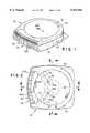
- FIG. 1is a generally perspective view of one form of the fluid delivery portion of the device of the present invention.
- FIG. 2is a top plan view of the device shown in FIG. 1.
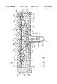
- FIG. 3is an enlarged, cross-sectional view taken along lines 3--3 FIG. 2.
- FIG. 4is an enlarged cross-sectional view taken along lines 4--4 of FIG. 2.
- FIG. 5is an exploded, cross-sectional view of the device shown in FIG. 4.
- FIG. 6is an exploded, cross-sectional view of one form of the infusion means of the device which comprises the lower assembly shown in FIG. 5.
- FIG. 7is a view taken along lines 7--7 of FIG. 5.
- FIG. 7Ais a cross-sectional view taken along lines 7A--7A of FIG. 7.
- FIG. 7Bis a cross-sectional view taken along lines 7B--7B of FIG. 7.
- FIG. 8is a view taken along lines 8--8 of FIG. 5.
- FIG. 9is a view taken along lines 9--9 of FIG. 5.
- FIG. 10is a view taken along lines 10--10 of FIG. 6.
- FIG. 11is a cross-sectional view taken along lines 11--11 of FIG. 10.
- FIG. 12is a cross-sectional view taken along lines 12--12 of FIG. 9.
- FIG. 13Ais top plan view of the back plate of the flow indicator assembly of the invention.
- FIG. 13Bis a rear view of the indicator assembly back plate shown in FIG. 13A.
- FIG. 14is a cross-sectional view similar to FIG. 3 but showing the centrally disposed reservoir and toroidal chamber of the device filled with a flowable liquid that comprises the ullage defining means of the invention.
- FIG. 15is a generally perspective view of the device similar to FIG. 1 but showing the fill means of the invention interconnected with the fluid delivery portion of the device.
- FIG. 16is a side-elevational, partly cross-sectional view showing the fill means interconnected with the fluid delivery portion of the device and showing the reservoirs of the device filled with the medicinal fluid to be infused into the patient.
- FIG. 17is a generally diagrammatic view illustrating the operation of the flow indicator means of the invention.
- FIG. 18Ais a top plan view of the flow indicator lens of the invention.
- FIG. 18Bis a front view of the flow indicator lens.
- FIG. 18Cis a right side elevational view of the flow indicator lens shown in FIG. 18A.
- FIGS. 1 through 5one form of the fluid delivery device of the present invention is there shown and generally designated by the numeral 20.
- This devicewhich is specially designed for sub dermal infusion of selected medicaments, comprises a base assembly 22 including a base component 22a having an upper surface 24 including a central portion 24a having an opening 24b (FIG. 5) and a peripheral portion 24c circumscribing central portion 24a.
- base assembly 22is also provided with a lower surface 26 to which a patient interconnection means or adhesive pad assembly 28 is connected (FIG. 3).
- pad assembly 28which includes a foam pad 28a and a peel strip 28b, functions to releasably interconnect the device to the patient so as to hold it securely in place during the medicament delivery step.
- An infusion meanswhich includes a reservoir defining housing 30 that is receivable within opening 24b of base component 22a, functions to controllably deliver medicament to the patient when the device is operatively affixed to the patient.
- a stored energy meansoverlays the upper surface 24 of base assembly 22 and cooperates with housing 30 to form a central medicinal fluid reservoir 32.
- Reservoir 32has an inlet port 34 (FIG. 3) which communicates, via a pierceable septum 36, with a filling means shown here as a filling syringe 38 which is partially receivable within a fill opening 39 formed in base assembly 22 (see FIG. 15 and 16).
- the stored energy meansis here provided in the form of at least one distendable membrane 40 which is superimposed over base assembly 22.
- Membrane 40which is distendable as a result of pressure imparted on the membrane by fluids introduced into the reservoirs of the device, includes a central portion 40a and a peripheral portion 40b.
- membrane 40As membrane 40 is distended in the manner shown in FIG. 16, substantial internal stresses will be established in the peripheral portion 40b of the membrane, which stresses tend to move the membrane toward a less distended configuration and in a direction toward its starting position as shown in FIG. 3. For reasons to be discussed later, filling of the reservoir in the manner shown in FIG. 16 will prestress the central portion 40a of the membrane a predetermined amount. It is to be understood that membrane 40 can be constructed from a single membrane or from multiple membranes joined together to form a laminate construction.
- the central portion of membrane 40cooperates with a surface 30a of housing 30 to form the expandable and contractable central medicinal fluid reservoir 32.
- the peripheral portion of membrane 40also cooperates with base assemblage 22 to form an indicator fluid reservoir 42, the character and purpose of which will be more fully described hereinafter.
- cover assembly 44Superimposed over and sealably connected to base assembly 22 by any suitable means such as sonic welding is a cover assembly 44.
- the peripheral portion 44a of cover assembly 44cooperates with the peripheral portion of membrane 40 to form a peripheral, generally toroidal-shaped, conformable ullage reservoir 46.
- the central portion 44b of cover assembly 44cooperates with the central portion of membrane 40 to form a central conformable ullage reservoir 48.
- the novel ullage defining means of the inventionDisposed within reservoirs 46 and 48 is the novel ullage defining means of the invention which here comprises a flowable mass, such as an oil.
- this flowable massis acted upon by the distendable membrane as the membrane, after being distended by the filling of reservoir 46, tends to return to its less distended configuration.
- the ullage oil contained within reservoir 46will be urged to flow uniformly outwardly of reservoir 46 and into central reservoir 48.
- a barrier member 49is disposed between the central portion of the distendable membrane 40 and a surface 30a of housing 30.
- the fluid introduced through inlet port 34 of the medicinal fluid reservoirwill impinge first upon barrier member 49.
- the barrier memberwill, in turn, act upon the central portion of the prestressed distendable membrane 40 causing it to distend toward cover 44 in the manner shown in FIG. 16.
- Cover assembly 44includes a rigid cover member 50, which having a generally circular energy director 51 (FIG. 5) expedites the sonic welding of cover 50 to base assembly 22.
- sealing meansare provided to sealably connect cover 50 to base assembly 22.
- These novel sealing meanshere comprise a first elastomeric insert 52 which forms a part of base assembly 22.
- insert 52is provided with circular grooves 54 and 56.
- an elastomeric insert 57which forms a part of cover assembly 44. Insert 57 is provided with generally circular-shaped protuberances 58 and 60. As best seen in FIG.
- protuberance 58is sealably receivable within groove 54 of insert 52, while protuberance 60 is sealably received in groove 56 of insert 52.
- protuberance 58 and 60function to sealably clamp distendable membrane 40 between the cover and base assemblies.
- Inserts 52 and 57are preferably formed from a suitable elastomeric material which, in a manner well understood by those skilled in the art, is injected into circular shaped cavities 22b and 50a formed in base assembly 22 and cover 50 respectively. It is to be noted that cavity 22b includes a semicircular shaped groove 51 which receives a semicircular protuberance 52a formed on insert 52 (FIG. 5). Insert 52 also includes a generally toroidal shaped cavity 52b which, along with membrane 40, forms the previously mentioned indicator fluid reservoir 42.
- Elastomers suitable for forming inserts 52 and 57include any non-coring elastomeric material, including silicones, polyolyfins and other TPE rubbers. With respect tO the distendable membrane 40 and the barrier membrane 49, these important components can be constructed from a number of different materials including rubbers, plastics and other thermoplastic elastomers. These include latex rubber, polyisoprene (natural rubber), butyl rubber, nitrile rubber, other homopolymer, copolymers (random, alternating, block, graft, crosslink and starblock), mechanical poly-blends and interpenetrating polymer networks.
- the flowable materialcan be selected from a variety of viscous fluids. Fluids such as water, mineral oil, peanut oil, silicone oil, glycerine, and methyl cellulose can be used. The choice of fluid is, in part, determined by the fluid viscosity centipoise requirements needed to achieve the desired rate of delivery, and in part, by the material used to construct the distendable membrane.
- fluorinated oilsare extremely pure and stable, and therefore they are nonreactive with the elastomers that can be used to construct the distendable membrane of the current invention. Fluorinated oils are also available in a range of viscosities suitable to this application.
- fluorinated oil suitable for use as the ullage defining meansis available from DuPont and is sold under the name and style KRYTOX.
- these componentscan also be produced from a variety of materials including one of several polymer groups.
- the degree of hardness of these materialscan range from soft, resilient or rigid, and the following polymers can be employed: Polypropylene (PP), Ultra high molecular weight polyethylene (UHMW PE), High density polyethylene (HDPE), Polyvinylidene Fluoride (PVDF), Ethylene-vinyl acetate (EVA), Styrene Acrylonitrile (SAN), Polytetrafluoroethylene (PTFF).
- PPPolypropylene
- UHMW PEUltra high molecular weight polyethylene
- HDPEHigh density polyethylene
- PVDFPolyvinylidene Fluoride
- EVAEthylene-vinyl acetate
- SANStyrene Acrylonitrile
- PTFFPolytetrafluoroethylene
- the foam pad adhesive 28a and peel strip 28bis preferably composed of a thin (1/32") 30 mil closed cell polyethylene (PE) foam double coated with a non-sensitizing acrylic pressure sensitive adhesive (PSA), and 90 lb. white polyethylene coated release liner (peel strip).
- This foamis also available in 1/16 inch and 1/8 inch thickness.
- the foamis stretchable, soft, elastically conformable, cushioning, hypoallergenic, and is desirable for application where sustained use is required.
- the materialis available from the 3M Company of Saint Paul, Minn. and from Betham Corporation of Middlesex, N.J.
- the infusion means of this latest form of the invention for subdermal infusion of medicaments into the patientcan be seen to include, in addition to reservoir defining housing 30, a downwardly extending hollow cannula 64 which is carried by a disk-like support member 66.
- Support member 66is closely received within a cannula assembly housing 68 which, in turn, is closely received within a cavity 70 formed in reservoir defining housing 30.
- Hollow cannula 64includes a body portion 64a having an inlet end 65, and an outlet end 67 formed in a needle-like segment which extends generally perpendicularly downward from the lower surface of base assembly 22.
- an impedance frit 72Disposed between inlet end 65 of cannula 64 and medicament reservoir 32 is an impedance frit 72 which forms a part of the flow control means of the invention for controlling fluid flow from reservoir 32 toward the patient.
- a protective cover 74surrounds the cannula.
- the skirt portion 74a of the protective cover 74can be readily separated from the base portion 74b of the cover by breaking it away along a serration line 75 formed between the skirt portion 74a and the base portion 74b.
- the first step in preparing the device for useis filling of the ullage reservoirs with the ullage-defining means. This is accomplished using a conventional syringe, the filling needle of which is inserted into an inlet port 78 formed in cover assembly 44 (FIGS. 2 and 7). During the ullage reservoir filling step, air contained within the reservoirs is vented through vent 80 (FIGS. 2 and 7). Referring particularly to FIGS.
- cover 50 of cover assembly 44is provided with a centrally disposed cavity 58 which overlays the central portion of distendable membrane 40 and cooperates therewith to form the central conformable ullage reservoir 48 (FIGS. 3 and 14).
- the ullage defining meansin this case a flowable mass such as a viscous oil "CU”
- inlet port 78flows from inlet port 78 through flow channel 85 and into central conformable ullage reservoir 48 (FIG. 7).
- thiscauses the central portion of distendable membrane 40a along with the central portion of barrier membrane 49 to distend downwardly in a direction toward the upper, concave surface 30a of member 30 of base assembly 22. It is important to note that this downward extension of the central portion of the membrane causes a buildup of internal stresses in this portion of the membrane which mitigates against its ability to return to its starting position following filling of the medicament reservoir in a manner presently to be discussed.
- central ullage reservoir 48 and peripheral ullage reservoir 46are connected by first and second passageways 84 and 86 formed in cover member 50.
- the viscous oilwhich forms the ullage defining means of the present embodiment of the invention, can flow into and out of central ullage reservoir 48 both during the medicinal reservoir filling step and also during the infusion step during which the medicinal fluid is infused into the patient.
- FIG. 14simultaneously with filling of central ullage reservoir 48 is the filling of the generally toroidal-shaped, conformable ullage reservoir 46 via fluid flow passageway 86. Filling of ullage reservoir 46 causes the peripheral portion of distendable membrane 40 to distend downwardly toward elastomeric insert 52 which is formed in base assembly 22.
- the next step in readying the device of the invention for useis the fluid indicator reservoir filling step wherein an appropriate indicator fluid such as a colored oil is caused to flow into reservoir 42.
- This colored oilwhich is designated in FIG. 14 by the numeral 42a, can comprise several types of oil including peanut oil.
- Fluid indicator reservoir 42is filled with the indicator fluid 42a using conventional syringe of the character having a pierceable needle which is inserted into a fill port 90 formed in base assembly 22 (FIG. 9).
- the next step in preparing the device for useis the filling of the medicinal fluid reservoir 32.
- Thisis accomplished using the previously mentioned fill means of the invention which here comprises the filling syringe 38.
- filling syringe 38which is of conventional construction, includes a hollow piercing cannula 38a.
- piercing cannula 38awill pierce septum 36 and permit the flow medicinal fluid from the fluid reservoir of the syringe assembly 38 into the inlet port 34 of the medicinal fluid reservoir 32.
- Filling of reservoir 32 with the medicinal fluidcauses the barrier membrane 49 to exert forces against the central portion of distendable membrane 40, which has previously been prestressed during filling of the ullage reservoir, causing it to distend upwardly in a direction toward cover member 50.
- the viscous oil "CU”which comprises the ullage-defining means which can range from centipoise one to greater than centipoise one-hundred of the invention will be caused to flow through passageway 86 from central reservoir 48 into peripheral reservoir 46.
- FIGS. 14 and 16show that, as the flowable mass "CU” flows from central reservoir 48 toward peripheral reservoir 46, the indicator fluid disposed within peripheral reservoir 42 will be urged outwardly of the reservoir and, in a manner presently to be described, will flow into the indicator means of the invention.
- this indicator meansfunctions to indicate the flow of medicinal fluid from central medicinal fluid reservoir 32 outwardly of the device through the infusion means.
- this important indicator meanscomprises an indicator lens assembly 94 which is interconnected with base assembly 22 to form the completed fluid delivery portion of the device shown in FIG. 1.
- Indicator lens assembly 94includes a body portion 96 (FIGS. 18A and 18B) within which is formed a circuitous indicator fluid flow path 98.
- This circuitous fluid flow pathcomprises a plurality of interconnected, generally U-shaped flow passageways 98a which are disposed in close proximity along the length of body portion 96. When these passageways are viewed through the indicator lens 100, they appear as a series of spaced apart parallel lines.
- an indicator fluid pick-up means or tube 102is provided proximate one end of back plate 95, while a vent means shown here as a porous gas vent 104 is provided proximate the opposite end of back plate 95.
- base assembly 22is provided with an elongated bore 106 which receives pick-up tube assembly 102 in a manner to place the pick-up tube in communication with peripheral fluid indicator reservoir 42.
- base assembly 22is provided with a bore 108 which is adapted to receive porous gas vent assembly 104 so that the assembly can communicate with atmosphere to enable appropriate venting of the indicator lens assembly during the indicator oil filling step.
- the deviceWith the various reservoirs of the device filled in the manner shown in FIG. 16, the device is in condition for use in infusing medicinal fluid into the patient. This is accomplished by breaking away of protective shroud 74 so as to expose cannula 64 and by removing the lower peel strip 28b of the pad assembly 28. A downward pressure exerted on the device will then cause infusion cannula 64 to pierce the skin and tissue of the patient and to bring the lower adhesive covered surface of the pad assembly into contact with the patient's skin so as to securely interconnect the device with the patient during the infusion step.
- the first of these novel flow control meansis carried by cover assembly 44 and functions to permit the viscous oil "CU" which comprises the ullage defining means of the invention to flow in a first direction from central conformable ullage reservoir 48 toward generally toroidal shaped conformable ullage reservoir 46 via first fluid passageway 84 formed in cover member 50 (FIG. 2).
- This first flow control meansis here provided in the form of a one-way valve means or valve 110 (FIGS. 2, 7 and 7A).
- This novel one-way valve 110which is housed within port 84a of passageway 84, permits the ullage medium or viscous oil "CU” to flow in a first direction from central ullage reservoir 48 toward peripheral reservoir 46 via port 84b (FIG. 7), but prevents flow of the ullage oil in the opposite direction.
- the second important flow control means of the inventioncomprises a flow rate control means carried by cover assembly 44 for controlling the rate of flow of the ullage defining means or ullage oil "CU" between generally toroidal shaped conformable ullage reservoir 46 and central conformable ullage reservoir 48 via second passageway 86 (FIG. 2).
- This important flow rate control meansis here provided in the form of a rate control frit 112 which, as best seen in FIGS. 2, 7 and 7B, is mounted within a port 86a of passageway 86 so as to control the rate of flow of the ullage oil from peripheral ullage reservoir 46 back toward central ullage reservoir 48 via port 86b (FIG. 7B).
- This flow of indicator oil from passageway 98will, of course, be proportional to the flow of medicinal fluid outwardly of the device from medicinal fluid reservoir 32.
- the indicator oilWhen the indicator oil is viewed through indicator lens 100, the user will see a progressive emptying of the colored lines defined by circuitous flow passageway 98 from one side of the lens to the other indicating not only that fluid is flowing from medicinal reservoir 32, but also indicating the amount of fluid remaining in the reservoir and the rate of flow of fluid therefrom.
- lines 98awill appear red in color along the entire length of the viewing lens. However, as the reservoir empties a progressively fewer number of the lines will appear red in color much in the same manner as a gasoline gage in an automobile.
- Still another flow control means of the inventioncomprises a second fluid flow control means which is carried by base assembly 22 for restricting the flow of medicinal fluid from central medicinal fluid reservoir 32 toward inlet 65 of piercing cannula 64.
- This second flow control meansis here provided in the form of the previously identified impedance frit 72 for control of environmental perturbations such as shock and vibration.
- impedance frit 72which is disposed between the outlet of reservoir 32 and the inlet 65 of cannula 64, can be constructed of various materials, but a material such as stainless steel, porous plastic or porous ceramic which is readily available from numerous sources well known to those skilled in the art has proven suitable for the intended use.
- FIG. 17a diagrammatic representation of the flow paths of the various fluids contained within the device of the invention is there illustrated.
- the needle of assembly 64 and impedance frit 72are shown interconnected with medicinal fluid reservoir 32.
- Reservoir 32can be filled in the manner described using the fill means or fill assembly generally designated by the numeral 38.
- Disposed between central ullage reservoir 48 and medicinal fluid reservoir 32is the central portion of the stored energy means or the central portion 40a of the distendable membrane 40.
- Flow of the ullage mediumin this case a flowable mass such as viscous oil "CU", is flowable from central ullage reservoir 48 to peripheral ullage reservoir 46 via one-way valve 110 which controls fluid flow through first flow passageway 84 formed in cover member 50.
- a flowable masssuch as viscous oil "CU”
- Flow of the ullage mediumis flowable from central ullage reservoir 48 to peripheral ullage reservoir 46 via one-way valve 110 which controls fluid flow through first flow passageway 84 formed in cover member 50.
- Separating toroidal shaped ullage reservoir 48 and indicator fluid reservoir 42is the peripheral portion 40b of the distendable membrane 40.
- indicator fluid reservoir 42can be filled with indicator fluid 42a via fill port 90.
- indicator tube assembly 102Interconnected with indicator fluid reservoir 42 via indicator tube assembly 102 is circuitous flow passageway 98 of body 96 of the indicator means "I" of the invention.
- the novel flow rate control means of the inventionor frit 112 is disposed within second passageway 86 formed in
- membrane portion 40awill be distended in a manner to cause the ullage contained in central reservoir 48 to flow into peripheral reservoir 46 via passageway 84 and one-way valve means 110. This will, in turn, cause the peripheral portion 40b of the distendable membrane 40 to urge the indicator fluid contained within reservoir 42 outwardly thereof via tube assembly 102 into passageway 98 formed in indicator body 96. This outward flow of indicator fluid will fill passageway 98 indicating a filled condition of the medicinal fluid reservoir when the indicator body is viewed through indicator lens 100.
- the indicator oilwill be urged to flow outwardly of circuitous passageway 98 in a direction back toward indicator fluid reservoir 42.
- the body as viewed through indicator lens 100will evidence a continued decrease in the number of lines viewed through indicator lens 100 which evidence the red color. This decrease in the lines showing color will indicate not only that fluid is flowing from medicinal reservoir 32, but will also indicate the rate of such flow and the amount of fluid remaining within the fluid reservoir.
Landscapes
- Health & Medical Sciences (AREA)
- Engineering & Computer Science (AREA)
- Public Health (AREA)
- Life Sciences & Earth Sciences (AREA)
- Veterinary Medicine (AREA)
- Anesthesiology (AREA)
- Biomedical Technology (AREA)
- Heart & Thoracic Surgery (AREA)
- Hematology (AREA)
- General Health & Medical Sciences (AREA)
- Animal Behavior & Ethology (AREA)
- Vascular Medicine (AREA)
- Bioinformatics & Cheminformatics (AREA)
- Chemical & Material Sciences (AREA)
- Medicinal Chemistry (AREA)
- Infusion, Injection, And Reservoir Apparatuses (AREA)
Abstract
Description
Claims (24)
Priority Applications (3)
| Application Number | Priority Date | Filing Date | Title |
|---|---|---|---|
| US08/991,122US5921962A (en) | 1995-10-11 | 1997-12-16 | Fluid delivery device with flow indicator and rate control |
| PCT/US1998/026730WO1999030767A1 (en) | 1997-12-16 | 1998-12-16 | Fluid delivery device with flow indicator and rate control |
| AU18299/99AAU1829999A (en) | 1997-12-16 | 1998-12-16 | Fluid delivery device with flow indicator and rate control |
Applications Claiming Priority (3)
| Application Number | Priority Date | Filing Date | Title |
|---|---|---|---|
| US08/541,184US5776103A (en) | 1995-10-11 | 1995-10-11 | Fluid delivery device with bolus injection site |
| US08/606,090US5779676A (en) | 1995-10-11 | 1996-02-23 | Fluid delivery device with bolus injection site |
| US08/991,122US5921962A (en) | 1995-10-11 | 1997-12-16 | Fluid delivery device with flow indicator and rate control |
Related Parent Applications (1)
| Application Number | Title | Priority Date | Filing Date |
|---|---|---|---|
| US08/606,090Continuation-In-PartUS5779676A (en) | 1995-10-11 | 1996-02-23 | Fluid delivery device with bolus injection site |
Publications (1)
| Publication Number | Publication Date |
|---|---|
| US5921962Atrue US5921962A (en) | 1999-07-13 |
Family
ID=25536902
Family Applications (1)
| Application Number | Title | Priority Date | Filing Date |
|---|---|---|---|
| US08/991,122Expired - Fee RelatedUS5921962A (en) | 1995-10-11 | 1997-12-16 | Fluid delivery device with flow indicator and rate control |
Country Status (3)
| Country | Link |
|---|---|
| US (1) | US5921962A (en) |
| AU (1) | AU1829999A (en) |
| WO (1) | WO1999030767A1 (en) |
Cited By (58)
| Publication number | Priority date | Publication date | Assignee | Title |
|---|---|---|---|---|
| US6063058A (en)* | 1997-03-12 | 2000-05-16 | Piolax, Inc. | Liquid medicine continous infuser |
| USD439657S1 (en) | 1999-10-19 | 2001-03-27 | Baxter International Inc. | Push button fluid delivery controller |
| USD471274S1 (en) | 2002-02-23 | 2003-03-04 | Stryker Instruments | Medication delivery pump |
| US20030187394A1 (en)* | 2002-04-02 | 2003-10-02 | Wilkinson Bradley M | Method and device for intradermally delivering a substance |
| US20030216684A1 (en)* | 2002-03-26 | 2003-11-20 | Fentress James K. | Multi-stage fluid delivery device and method |
| US20040092875A1 (en)* | 2002-11-08 | 2004-05-13 | Kochamba Gary Steven | Cutaneous injection delivery under suction |
| US20040138612A1 (en)* | 2002-07-22 | 2004-07-15 | Shermer Charles D. | Patch-like infusion device |
| US20050033233A1 (en)* | 2003-08-04 | 2005-02-10 | Kriesel Marshall S. | Infusion apparatus with constant force spring energy source |
| US20050033232A1 (en)* | 2003-08-05 | 2005-02-10 | Kriesel Marshall S. | Infusion apparatus with modulated flow control |
| US20050038387A1 (en)* | 2003-08-04 | 2005-02-17 | Kriesel Marshall S. | Multichannel fluid delivery device |
| US20050065472A1 (en)* | 2003-07-22 | 2005-03-24 | Cindrich Chris N. | Patch-like infusion device |
| US20050119796A1 (en)* | 2003-11-27 | 2005-06-02 | Adrian Steiner | Method and apparatus to control the rate of flow of a fluid through a conduit |
| KR100514151B1 (en)* | 2001-10-12 | 2005-09-13 | 이영규 | Drug injection controller |
| US20050263615A1 (en)* | 2004-05-26 | 2005-12-01 | Kriesel Marshall S | Fluid delivery apparatus with adjustable flow rate control |
| US20050277882A1 (en)* | 2004-05-26 | 2005-12-15 | Kriesel Marshall S | Infusion apparatus |
| US20050277883A1 (en)* | 2004-05-26 | 2005-12-15 | Kriesel Marshall S | Fluid delivery device |
| US20050277884A1 (en)* | 2004-05-26 | 2005-12-15 | Kriesel Marshall S | Fluid delivery apparatus with bellows reservoir |
| US20060195057A1 (en)* | 2005-02-18 | 2006-08-31 | Kriesel Marshall S | Fluid delivery apparatus with vial fill |
| US20060196552A1 (en)* | 2005-02-17 | 2006-09-07 | Kriesel Marshall S | Distal rate control device |
| US20060206052A1 (en)* | 2005-02-15 | 2006-09-14 | Kriesel Marshall S | Fluid delivery and mixing apparatus with flow rate control |
| US20060264926A1 (en)* | 2002-11-08 | 2006-11-23 | Kochamba Gary S | Cutaneous stabilization by vacuum for delivery of micro-needle array |
| US20070156090A1 (en)* | 2004-05-26 | 2007-07-05 | Kriesel Marshall S | Fluid delivery apparatus |
| US20070219501A1 (en)* | 2006-03-15 | 2007-09-20 | Kriesel Marshall S | Fluid dispensing apparatus |
| US20080009835A1 (en)* | 2005-02-17 | 2008-01-10 | Kriesel Marshall S | Fluid dispensing apparatus with flow rate control |
| US20080027376A1 (en)* | 2006-07-31 | 2008-01-31 | Kriesel Marshall S | Fluid dispensing device with additive |
| US20080061081A1 (en)* | 2004-06-02 | 2008-03-13 | Nestec S.A. | Device and method for hygienically deliverying a liquid |
| US20080243077A1 (en)* | 2007-04-02 | 2008-10-02 | Bivin Donald B | Fluid dispenser with uniformly collapsible reservoir |
| USD580047S1 (en)* | 2006-05-09 | 2008-11-04 | Medela Holding Ag | Medical drainage pump |
| US20080319385A1 (en)* | 2007-06-25 | 2008-12-25 | Kriesel Marshall S | Fluid dispenser with additive sub-system |
| USD585132S1 (en)* | 2006-10-24 | 2009-01-20 | Medela Holding Ag | Medical drainage pump |
| US20090024083A1 (en)* | 2007-06-25 | 2009-01-22 | Kriesel Marshall S | Fluid dispenser with additive sub-system |
| USD587364S1 (en)* | 2006-11-09 | 2009-02-24 | Medela Holding Ag | Medical drainage pump |
| US7530968B2 (en) | 2003-04-23 | 2009-05-12 | Valeritas, Inc. | Hydraulically actuated pump for long duration medicament administration |
| US20090163866A1 (en)* | 2007-12-19 | 2009-06-25 | Seattle Medical Technologies, Inc. | Disposable infusion device negative pressure filling apparatus and method |
| US20090171311A1 (en)* | 2007-12-28 | 2009-07-02 | Aktivpak, Inc. | Dispenser and therapeutic package suitable for administering a therapeutic substance to a subject, along with method relating to same |
| US20090326456A1 (en)* | 2008-06-26 | 2009-12-31 | Calibra Medical, Inc. | Disposable infusion device with prime indicator |
| US20100121446A1 (en)* | 2007-02-19 | 2010-05-13 | Ticapex Ab | Implant assembly |
| US20100179473A1 (en)* | 2006-12-29 | 2010-07-15 | Amir Genosar | Hypodermic drug delivery reservoir and apparatus |
| US7828772B2 (en) | 2006-03-15 | 2010-11-09 | Bioquiddity, Inc. | Fluid dispensing device |
| US20100292670A1 (en)* | 2007-10-09 | 2010-11-18 | Bruno Gogly | Device for administering cells and cell-therapy methods using said device |
| US7914499B2 (en) | 2006-03-30 | 2011-03-29 | Valeritas, Inc. | Multi-cartridge fluid delivery device |
| US20110172601A1 (en)* | 2010-01-08 | 2011-07-14 | Beebe David J | Bladder Arrangement For Microneedle-Based Drug Delivery Device |
| US20110230833A1 (en)* | 2010-03-21 | 2011-09-22 | Mania Landman | Device and Method for Injecting Fluids or Gels |
| US8057435B2 (en) | 2006-07-31 | 2011-11-15 | Kriesel Joshua W | Fluid dispenser |
| US8945071B2 (en) | 2010-09-02 | 2015-02-03 | Becton, Dickinson And Company | Self-injection device having needle cover with activation preventer |
| US8961469B2 (en) | 2009-12-16 | 2015-02-24 | Becton, Dickinson And Company | Self-injection device |
| US20150119821A1 (en)* | 2013-10-25 | 2015-04-30 | Medtronic, Inc. | Prefilled reservoir apparatus for ambulatory infusion device |
| US9089636B2 (en) | 2004-07-02 | 2015-07-28 | Valeritas, Inc. | Methods and devices for delivering GLP-1 and uses thereof |
| US9555187B2 (en) | 2009-12-16 | 2017-01-31 | Becton, Dickinson And Company | Self-injection device |
| US9579461B2 (en) | 2009-12-16 | 2017-02-28 | Becton, Dickinson And Company | Self-injection device |
| US9717850B2 (en) | 2009-12-16 | 2017-08-01 | Becton, Dickinson And Company | Self-injection device |
| US9833562B2 (en) | 2009-12-16 | 2017-12-05 | Becton, Dickinson And Company | Self-injection device |
| US9987428B2 (en) | 2011-10-14 | 2018-06-05 | Amgen Inc. | Injector and method of assembly |
| US10195340B2 (en) | 2009-12-16 | 2019-02-05 | Becton, Dickinson And Company | Self-injection device |
| US20200046907A1 (en)* | 2016-11-01 | 2020-02-13 | Sanofi-Aventis Deutschland Gmbh | Feedback Mechanism for an Injection Device |
| US10850037B2 (en) | 2013-03-22 | 2020-12-01 | Amgen Inc. | Injector and method of assembly |
| US11097055B2 (en) | 2013-10-24 | 2021-08-24 | Amgen Inc. | Injector and method of assembly |
| US11324882B2 (en)* | 2017-10-05 | 2022-05-10 | Pirouette Medical Inc. | Protective case for an auto-injector |
Families Citing this family (1)
| Publication number | Priority date | Publication date | Assignee | Title |
|---|---|---|---|---|
| CN102971026A (en)* | 2010-06-30 | 2013-03-13 | 泰尔茂株式会社 | Drug injection apparatus and drug container |
Citations (5)
| Publication number | Priority date | Publication date | Assignee | Title |
|---|---|---|---|---|
| US4193397A (en)* | 1977-12-01 | 1980-03-18 | Metal Bellows Corporation | Infusion apparatus and method |
| US4474575A (en)* | 1982-02-01 | 1984-10-02 | Alza Corporation | Self-driven pump assembly and method of operation |
| US4668231A (en)* | 1984-02-15 | 1987-05-26 | Cordis Corporation | Implantable hand-operable dispensers for fluid medicaments |
| US4968301A (en)* | 1989-02-02 | 1990-11-06 | Imed Corporation | Disposable infusion device |
| US4969873A (en)* | 1988-06-23 | 1990-11-13 | Annemarie Schlogl Gesellschaft m.b.H. & Co., KG | Device for dispensing active substances to a patient |
- 1997
- 1997-12-16USUS08/991,122patent/US5921962A/ennot_activeExpired - Fee Related
- 1998
- 1998-12-16AUAU18299/99Apatent/AU1829999A/ennot_activeAbandoned
- 1998-12-16WOPCT/US1998/026730patent/WO1999030767A1/enactiveApplication Filing
Patent Citations (5)
| Publication number | Priority date | Publication date | Assignee | Title |
|---|---|---|---|---|
| US4193397A (en)* | 1977-12-01 | 1980-03-18 | Metal Bellows Corporation | Infusion apparatus and method |
| US4474575A (en)* | 1982-02-01 | 1984-10-02 | Alza Corporation | Self-driven pump assembly and method of operation |
| US4668231A (en)* | 1984-02-15 | 1987-05-26 | Cordis Corporation | Implantable hand-operable dispensers for fluid medicaments |
| US4969873A (en)* | 1988-06-23 | 1990-11-13 | Annemarie Schlogl Gesellschaft m.b.H. & Co., KG | Device for dispensing active substances to a patient |
| US4968301A (en)* | 1989-02-02 | 1990-11-06 | Imed Corporation | Disposable infusion device |
Cited By (137)
| Publication number | Priority date | Publication date | Assignee | Title |
|---|---|---|---|---|
| US6063058A (en)* | 1997-03-12 | 2000-05-16 | Piolax, Inc. | Liquid medicine continous infuser |
| USD439657S1 (en) | 1999-10-19 | 2001-03-27 | Baxter International Inc. | Push button fluid delivery controller |
| KR100514151B1 (en)* | 2001-10-12 | 2005-09-13 | 이영규 | Drug injection controller |
| USD471274S1 (en) | 2002-02-23 | 2003-03-04 | Stryker Instruments | Medication delivery pump |
| US7214221B2 (en) | 2002-03-26 | 2007-05-08 | Becton, Dickinson And Company | Multi-stage fluid delivery device and method |
| US20030216684A1 (en)* | 2002-03-26 | 2003-11-20 | Fentress James K. | Multi-stage fluid delivery device and method |
| US7115108B2 (en)* | 2002-04-02 | 2006-10-03 | Becton, Dickinson And Company | Method and device for intradermally delivering a substance |
| US7410476B2 (en)* | 2002-04-02 | 2008-08-12 | Becton, Dickinson And Company | Method and device for intradermally delivering a substance |
| US20080287871A1 (en)* | 2002-04-02 | 2008-11-20 | Wilkinson Bradley M | Method and Device for Intradermally Delivering a Substance |
| US7896837B2 (en)* | 2002-04-02 | 2011-03-01 | Becton, Dickinson And Company | Method and device for intradermally delivering a substance |
| US20030187394A1 (en)* | 2002-04-02 | 2003-10-02 | Wilkinson Bradley M | Method and device for intradermally delivering a substance |
| US20050245877A1 (en)* | 2002-04-02 | 2005-11-03 | Becton, Dickinson And Company | Method and device for intradermally delivering a substance |
| US20070203454A1 (en)* | 2002-07-22 | 2007-08-30 | Shermer Charles D | Patch-Like Infusion Device |
| US7250037B2 (en) | 2002-07-22 | 2007-07-31 | Becton, Dickinson And Company | Patch-like infusion device |
| US7678079B2 (en) | 2002-07-22 | 2010-03-16 | Becton, Dickinson And Company | Patch-like infusion device |
| US20040138612A1 (en)* | 2002-07-22 | 2004-07-15 | Shermer Charles D. | Patch-like infusion device |
| US6896666B2 (en) | 2002-11-08 | 2005-05-24 | Kochamba Family Trust | Cutaneous injection delivery under suction |
| US20060264926A1 (en)* | 2002-11-08 | 2006-11-23 | Kochamba Gary S | Cutaneous stabilization by vacuum for delivery of micro-needle array |
| US20040092875A1 (en)* | 2002-11-08 | 2004-05-13 | Kochamba Gary Steven | Cutaneous injection delivery under suction |
| US20050165380A1 (en)* | 2002-11-08 | 2005-07-28 | Kochamba Family Trust | Cutaneous Injection Delivery Under Suction |
| US20070088348A1 (en)* | 2002-11-08 | 2007-04-19 | Medical Microdevices, Inc. | Stabilization by suction using micro-needles |
| US20070010810A1 (en)* | 2002-11-08 | 2007-01-11 | Kochamba Gary S | Ablation and micro-needles |
| US9125983B2 (en) | 2003-04-23 | 2015-09-08 | Valeritas, Inc. | Hydraulically actuated pump for fluid administration |
| US9072828B2 (en) | 2003-04-23 | 2015-07-07 | Valeritas, Inc. | Hydraulically actuated pump for long duration medicament administration |
| US10525194B2 (en) | 2003-04-23 | 2020-01-07 | Valeritas, Inc. | Hydraulically actuated pump for fluid administration |
| US11642456B2 (en) | 2003-04-23 | 2023-05-09 | Mannkind Corporation | Hydraulically actuated pump for fluid administration |
| US7530968B2 (en) | 2003-04-23 | 2009-05-12 | Valeritas, Inc. | Hydraulically actuated pump for long duration medicament administration |
| US8070726B2 (en) | 2003-04-23 | 2011-12-06 | Valeritas, Inc. | Hydraulically actuated pump for long duration medicament administration |
| US9511187B2 (en) | 2003-04-23 | 2016-12-06 | Valeritas, Inc. | Hydraulically actuated pump for fluid administration |
| US10589023B2 (en) | 2003-07-22 | 2020-03-17 | Becton, Dickinson And Company | Patch-like infusion device |
| US20050065472A1 (en)* | 2003-07-22 | 2005-03-24 | Cindrich Chris N. | Patch-like infusion device |
| US8512287B2 (en) | 2003-07-22 | 2013-08-20 | Becton, Dickinson And Company | Patch-like infusion device |
| US9364606B2 (en) | 2003-07-22 | 2016-06-14 | Becton, Dickinson And Company | Patch-like infusion device |
| US9597450B2 (en) | 2003-07-22 | 2017-03-21 | Becton, Dickinson And Company | Patch-like infusion device |
| US9999724B2 (en) | 2003-07-22 | 2018-06-19 | Becton, Dickinson And Company | Patch-like infusion device |
| US7789853B2 (en) | 2003-08-04 | 2010-09-07 | Bioquiddity, Inc. | Infusion apparatus with constant force spring energy source |
| US20080051701A1 (en)* | 2003-08-04 | 2008-02-28 | Kriesel Marshall S | Infusion apparatus with constant force spring energy source |
| US7169128B2 (en) | 2003-08-04 | 2007-01-30 | Bioquiddity, Inc. | Multichannel fluid delivery device |
| US20050033233A1 (en)* | 2003-08-04 | 2005-02-10 | Kriesel Marshall S. | Infusion apparatus with constant force spring energy source |
| US7220244B2 (en) | 2003-08-04 | 2007-05-22 | Bioquiddity, Inc. | Infusion apparatus with constant force spring energy source |
| US20050038387A1 (en)* | 2003-08-04 | 2005-02-17 | Kriesel Marshall S. | Multichannel fluid delivery device |
| US20050033232A1 (en)* | 2003-08-05 | 2005-02-10 | Kriesel Marshall S. | Infusion apparatus with modulated flow control |
| US8444604B2 (en) | 2003-08-12 | 2013-05-21 | Becton, Dickinson And Company | Patch-like infusion device |
| US20080215015A1 (en)* | 2003-08-12 | 2008-09-04 | Chris Cindrich | Patch-Like Infusion Device |
| US7857131B2 (en) | 2003-08-12 | 2010-12-28 | Becton, Dickinson And Company | Patch-like infusion device |
| US20050119796A1 (en)* | 2003-11-27 | 2005-06-02 | Adrian Steiner | Method and apparatus to control the rate of flow of a fluid through a conduit |
| US7702423B2 (en) | 2003-11-27 | 2010-04-20 | Weatherford Canada Partnership C/O Weatherford International Ltd. | Method and apparatus to control the rate of flow of a fluid through a conduit |
| US20050277882A1 (en)* | 2004-05-26 | 2005-12-15 | Kriesel Marshall S | Infusion apparatus |
| US20050277883A1 (en)* | 2004-05-26 | 2005-12-15 | Kriesel Marshall S | Fluid delivery device |
| US20050277884A1 (en)* | 2004-05-26 | 2005-12-15 | Kriesel Marshall S | Fluid delivery apparatus with bellows reservoir |
| US20050263615A1 (en)* | 2004-05-26 | 2005-12-01 | Kriesel Marshall S | Fluid delivery apparatus with adjustable flow rate control |
| US7470253B2 (en) | 2004-05-26 | 2008-12-30 | Bioquiddity, Inc. | Fluid delivery apparatus with adjustable flow rate control |
| US20070156090A1 (en)* | 2004-05-26 | 2007-07-05 | Kriesel Marshall S | Fluid delivery apparatus |
| US7220245B2 (en) | 2004-05-26 | 2007-05-22 | Kriesel Marshall S | Infusion apparatus |
| US7694850B2 (en)* | 2004-06-02 | 2010-04-13 | Nestec S.A. | Device and method for hygienically delivering a liquid |
| US20080061081A1 (en)* | 2004-06-02 | 2008-03-13 | Nestec S.A. | Device and method for hygienically deliverying a liquid |
| US9089636B2 (en) | 2004-07-02 | 2015-07-28 | Valeritas, Inc. | Methods and devices for delivering GLP-1 and uses thereof |
| US20060206052A1 (en)* | 2005-02-15 | 2006-09-14 | Kriesel Marshall S | Fluid delivery and mixing apparatus with flow rate control |
| US7694938B2 (en) | 2005-02-17 | 2010-04-13 | Bioquiddity, Inc. | Distal rate control device |
| US20060196552A1 (en)* | 2005-02-17 | 2006-09-07 | Kriesel Marshall S | Distal rate control device |
| US20080009835A1 (en)* | 2005-02-17 | 2008-01-10 | Kriesel Marshall S | Fluid dispensing apparatus with flow rate control |
| US20060195057A1 (en)* | 2005-02-18 | 2006-08-31 | Kriesel Marshall S | Fluid delivery apparatus with vial fill |
| US7837653B2 (en) | 2005-02-18 | 2010-11-23 | Bioquiddity, Inc. | Fluid delivery apparatus with vial fill |
| US8672885B2 (en)* | 2006-03-15 | 2014-03-18 | Marshall S. Kriesel | Fluid dispensing device |
| US20110282284A1 (en)* | 2006-03-15 | 2011-11-17 | Kriesel Marshall S | Fluid dispensing apparatus |
| US7828772B2 (en) | 2006-03-15 | 2010-11-09 | Bioquiddity, Inc. | Fluid dispensing device |
| US20110092904A1 (en)* | 2006-03-15 | 2011-04-21 | Kriesel Marshall S | Fluid dispensing device |
| US20070219501A1 (en)* | 2006-03-15 | 2007-09-20 | Kriesel Marshall S | Fluid dispensing apparatus |
| US7993304B2 (en) | 2006-03-15 | 2011-08-09 | Bioquiddity, Inc. | Fluid dispensing apparatus |
| US7914499B2 (en) | 2006-03-30 | 2011-03-29 | Valeritas, Inc. | Multi-cartridge fluid delivery device |
| US8361053B2 (en) | 2006-03-30 | 2013-01-29 | Valeritas, Inc. | Multi-cartridge fluid delivery device |
| US12246159B2 (en) | 2006-03-30 | 2025-03-11 | Mannkind Corporation | Multi-cartridge fluid delivery device |
| US9687599B2 (en) | 2006-03-30 | 2017-06-27 | Valeritas, Inc. | Multi-cartridge fluid delivery device |
| US10493199B2 (en) | 2006-03-30 | 2019-12-03 | Valeritas, Inc. | Multi-cartridge fluid delivery device |
| US8821443B2 (en) | 2006-03-30 | 2014-09-02 | Valeritas, Inc. | Multi-cartridge fluid delivery device |
| USD580047S1 (en)* | 2006-05-09 | 2008-11-04 | Medela Holding Ag | Medical drainage pump |
| USD580046S1 (en)* | 2006-05-09 | 2008-11-04 | Medela Holding Ag | Medical drainage pump |
| US8292848B2 (en) | 2006-07-31 | 2012-10-23 | Bio Quiddity, Inc. | Fluid dispensing device with additive |
| US20080027376A1 (en)* | 2006-07-31 | 2008-01-31 | Kriesel Marshall S | Fluid dispensing device with additive |
| US8057435B2 (en) | 2006-07-31 | 2011-11-15 | Kriesel Joshua W | Fluid dispenser |
| USD585132S1 (en)* | 2006-10-24 | 2009-01-20 | Medela Holding Ag | Medical drainage pump |
| USD587364S1 (en)* | 2006-11-09 | 2009-02-24 | Medela Holding Ag | Medical drainage pump |
| US8684968B2 (en)* | 2006-12-29 | 2014-04-01 | Aktivpak, Inc. | Hypodermic drug delivery reservoir and apparatus |
| US20100179473A1 (en)* | 2006-12-29 | 2010-07-15 | Amir Genosar | Hypodermic drug delivery reservoir and apparatus |
| US20100121446A1 (en)* | 2007-02-19 | 2010-05-13 | Ticapex Ab | Implant assembly |
| US20080243077A1 (en)* | 2007-04-02 | 2008-10-02 | Bivin Donald B | Fluid dispenser with uniformly collapsible reservoir |
| US20080319385A1 (en)* | 2007-06-25 | 2008-12-25 | Kriesel Marshall S | Fluid dispenser with additive sub-system |
| US20090024083A1 (en)* | 2007-06-25 | 2009-01-22 | Kriesel Marshall S | Fluid dispenser with additive sub-system |
| US8211059B2 (en) | 2007-06-25 | 2012-07-03 | Kriesel Marshall S | Fluid dispenser with additive sub-system |
| US20100292670A1 (en)* | 2007-10-09 | 2010-11-18 | Bruno Gogly | Device for administering cells and cell-therapy methods using said device |
| US7976505B2 (en)* | 2007-12-19 | 2011-07-12 | Calibra Medical, Inc. | Disposable infusion device negative pressure filling apparatus and method |
| US20090163866A1 (en)* | 2007-12-19 | 2009-06-25 | Seattle Medical Technologies, Inc. | Disposable infusion device negative pressure filling apparatus and method |
| US8663188B2 (en) | 2007-12-28 | 2014-03-04 | Aktivpak, Inc. | Dispenser and therapeutic package suitable for administering a therapeutic substance to a subject, along with method relating to same |
| US20090171311A1 (en)* | 2007-12-28 | 2009-07-02 | Aktivpak, Inc. | Dispenser and therapeutic package suitable for administering a therapeutic substance to a subject, along with method relating to same |
| US20090326456A1 (en)* | 2008-06-26 | 2009-12-31 | Calibra Medical, Inc. | Disposable infusion device with prime indicator |
| WO2009158651A3 (en)* | 2008-06-26 | 2010-03-11 | Calibra Medical, Inc. | Disposable infusion device with prime indicator |
| US7927306B2 (en)* | 2008-06-26 | 2011-04-19 | Calibra Medical, Inc. | Disposable infusion device with prime indicator |
| US9717850B2 (en) | 2009-12-16 | 2017-08-01 | Becton, Dickinson And Company | Self-injection device |
| US10357610B2 (en) | 2009-12-16 | 2019-07-23 | Becton, Dickinson And Company | Self-injection device |
| US9555187B2 (en) | 2009-12-16 | 2017-01-31 | Becton, Dickinson And Company | Self-injection device |
| US10967123B2 (en) | 2009-12-16 | 2021-04-06 | Becton, Dickinson And Company | Self-injection device |
| US10420881B2 (en) | 2009-12-16 | 2019-09-24 | Becton, Dickinson And Company | Self-injection device |
| US11007316B2 (en) | 2009-12-16 | 2021-05-18 | Becton, Dickinson And Company | Self-injection device |
| US9833562B2 (en) | 2009-12-16 | 2017-12-05 | Becton, Dickinson And Company | Self-injection device |
| US9919097B2 (en) | 2009-12-16 | 2018-03-20 | Becton, Dickinson And Company | Self-injection device |
| US9579461B2 (en) | 2009-12-16 | 2017-02-28 | Becton, Dickinson And Company | Self-injection device |
| US8961469B2 (en) | 2009-12-16 | 2015-02-24 | Becton, Dickinson And Company | Self-injection device |
| US10080846B2 (en) | 2009-12-16 | 2018-09-25 | Becton, Dickinson And Company | Self-injection device |
| US10195340B2 (en) | 2009-12-16 | 2019-02-05 | Becton, Dickinson And Company | Self-injection device |
| US8328757B2 (en)* | 2010-01-08 | 2012-12-11 | Wisconsin Alumni Research Foundation | Bladder arrangement for microneedle-based drug delivery device |
| US20110172601A1 (en)* | 2010-01-08 | 2011-07-14 | Beebe David J | Bladder Arrangement For Microneedle-Based Drug Delivery Device |
| US20110230833A1 (en)* | 2010-03-21 | 2011-09-22 | Mania Landman | Device and Method for Injecting Fluids or Gels |
| US8480621B2 (en) | 2010-03-21 | 2013-07-09 | Mania Landman | Device and method for injecting fluids or gels |
| US8945071B2 (en) | 2010-09-02 | 2015-02-03 | Becton, Dickinson And Company | Self-injection device having needle cover with activation preventer |
| US9675752B2 (en) | 2010-09-02 | 2017-06-13 | Becton, Dickinson And Company | Self-injection device having needle cover with activation preventer |
| US11160931B2 (en) | 2011-10-14 | 2021-11-02 | Amgen Inc. | Method of assembling and filling a drug delivery device |
| US11273260B2 (en) | 2011-10-14 | 2022-03-15 | Amgen Inc. | Injector and method of assembly |
| US10537682B2 (en) | 2011-10-14 | 2020-01-21 | Amgen Inc. | Injector and method of assembly |
| US12329943B2 (en) | 2011-10-14 | 2025-06-17 | Amgen Inc. | Injector and method of assembly |
| US10537681B2 (en) | 2011-10-14 | 2020-01-21 | Amgen Inc. | Injector and method of assembly |
| US10314976B2 (en) | 2011-10-14 | 2019-06-11 | Amgen Inc. | Method of assembling and filling a drug delivery device |
| US11058821B2 (en) | 2011-10-14 | 2021-07-13 | Amgen Inc. | Injector and method of assembly |
| US11298463B2 (en) | 2011-10-14 | 2022-04-12 | Amgen Inc. | Method of assembling and filling a drug delivery device |
| US11110225B2 (en) | 2011-10-14 | 2021-09-07 | Amgen Inc. | Injector and method of assembly |
| US11129941B2 (en)* | 2011-10-14 | 2021-09-28 | Amgen Inc. | Method of assembling and filling a drug delivery device |
| US9987428B2 (en) | 2011-10-14 | 2018-06-05 | Amgen Inc. | Injector and method of assembly |
| US11759571B2 (en) | 2013-03-22 | 2023-09-19 | Amgen Inc. | Injector and method of assembly |
| US10850037B2 (en) | 2013-03-22 | 2020-12-01 | Amgen Inc. | Injector and method of assembly |
| US11097055B2 (en) | 2013-10-24 | 2021-08-24 | Amgen Inc. | Injector and method of assembly |
| US12427260B2 (en) | 2013-10-24 | 2025-09-30 | Amgen Inc. | Injector and method of assembly |
| US20150119821A1 (en)* | 2013-10-25 | 2015-04-30 | Medtronic, Inc. | Prefilled reservoir apparatus for ambulatory infusion device |
| US9463889B2 (en)* | 2013-10-25 | 2016-10-11 | Medtronic, Inc. | Prefilled reservoir apparatus for ambulatory infusion device |
| US20200046907A1 (en)* | 2016-11-01 | 2020-02-13 | Sanofi-Aventis Deutschland Gmbh | Feedback Mechanism for an Injection Device |
| US11865315B2 (en)* | 2016-11-01 | 2024-01-09 | Sanofi-Aventis Deutschland Gmbh | Feedback mechanism for an injection device |
| US20240108810A1 (en)* | 2016-11-01 | 2024-04-04 | Sanofi-Aventis Deutschland Gmbh | Feedback Mechanism for an Injection Device |
| US12274868B2 (en)* | 2016-11-01 | 2025-04-15 | Sanofi-Aventis Deutschland Gmbh | Feedback mechanism for an injection device |
| US11324882B2 (en)* | 2017-10-05 | 2022-05-10 | Pirouette Medical Inc. | Protective case for an auto-injector |
Also Published As
| Publication number | Publication date |
|---|---|
| WO1999030767A1 (en) | 1999-06-24 |
| AU1829999A (en) | 1999-07-05 |
Similar Documents
| Publication | Publication Date | Title |
|---|---|---|
| US5921962A (en) | Fluid delivery device with flow indicator and rate control | |
| US5957891A (en) | Fluid delivery device with fill adapter | |
| US5885250A (en) | Fluid delivery device with conformable ullage | |
| US5925017A (en) | Fluid delivery device with bolus injection site | |
| US5693018A (en) | Subdermal delivery device | |
| US5779676A (en) | Fluid delivery device with bolus injection site | |
| US6126637A (en) | Fluid delivery device with collapsible needle cover | |
| US6537249B2 (en) | Multiple canopy | |
| US5830187A (en) | Fluid delivery device with conformable ullage and fill assembly | |
| EP1464351B1 (en) | Low-profile automatic injection device with self-emptying reservoir | |
| US5019047A (en) | Fluid delivery apparatus | |
| US5468226A (en) | Fluid delivery apparatus having a stored energy source | |
| US5169389A (en) | Fluid delivery apparatus | |
| US5656032A (en) | Fluid delivery apparatus and method of making same | |
| US5205820A (en) | Fluid delivery apparatus | |
| US5352201A (en) | Compact uniform pressure infusion apparatus | |
| US5334197A (en) | Flexible base fluid delivery apparatus | |
| AU644550B2 (en) | Fluid delivery apparatus | |
| AU700421B2 (en) | Fluid delivery apparatus |
Legal Events
| Date | Code | Title | Description |
|---|---|---|---|
| AS | Assignment | Owner name:SCIENCE INCORPORATED, MINNESOTA Free format text:ASSIGNMENT OF ASSIGNORS INTEREST;ASSIGNORS:KRIESEL, MARSHALL S.;KAZEMZADEH, FARHAD;KRIESEL, MATTHEW B.;AND OTHERS;REEL/FRAME:009824/0425 Effective date:19970218 | |
| AS | Assignment | Owner name:WALLIN R. WALLIN D/B/A WALLIN FAMILY FOUNDATION, M Free format text:SECURITY INTEREST;ASSIGNOR:SCIENCE INCORPORATED;REEL/FRAME:011958/0404 Effective date:20001106 Owner name:WILLIAM F. FARLEY D/B/A LIVINGSTON CAPITAL, MINNES Free format text:SECURITY INTEREST;ASSIGNOR:SCIENCE INCORPORATED;REEL/FRAME:011958/0404 Effective date:20001106 Owner name:HODDER, WILLIAM A., MINNESOTA Free format text:SECURITY INTEREST;ASSIGNOR:SCIENCE INCORPORATED;REEL/FRAME:011958/0404 Effective date:20001106 Owner name:BRATTAIN, DONALD, MINNESOTA Free format text:SECURITY INTEREST;ASSIGNOR:SCIENCE INCORPORATED;REEL/FRAME:011958/0404 Effective date:20001106 Owner name:BEDNARCZYK, W. WILLIAM, MINNESOTA Free format text:SECURITY INTEREST;ASSIGNOR:SCIENCE INCORPORATED;REEL/FRAME:011958/0404 Effective date:20001106 Owner name:SIT INVESTMENT ASSOCIATES, INC., BY EUGENE C. SIT, Free format text:SECURITY INTEREST;ASSIGNOR:SCIENCE INCORPORATED;REEL/FRAME:011958/0404 Effective date:20001106 Owner name:GROSSMAN INVESTMENTS D/B/A N. BUD GROSSMAN, MANAGI Free format text:SECURITY INTEREST;ASSIGNOR:SCIENCE INCORPORATED;REEL/FRAME:011958/0404 Effective date:20001106 Owner name:OKABENA PARTNERSHIP V-8 BY OKABENA INVESTMENT SERV Free format text:SECURITY INTEREST;ASSIGNOR:SCIENCE INCORPORATED;REEL/FRAME:011958/0404 Effective date:20001106 Owner name:DAVID E. KELBY AND VIRGINIA H. KELBY, AS JOINT TEN Free format text:SECURITY INTEREST;ASSIGNOR:SCIENCE INCORPORATED;REEL/FRAME:011958/0404 Effective date:20001106 | |
| FEPP | Fee payment procedure | Free format text:PAT HOLDER CLAIMS SMALL ENTITY STATUS, ENTITY STATUS SET TO SMALL (ORIGINAL EVENT CODE: LTOS); ENTITY STATUS OF PATENT OWNER: SMALL ENTITY | |
| REFU | Refund | Free format text:REFUND - SURCHARGE FOR LATE PAYMENT, LARGE ENTITY (ORIGINAL EVENT CODE: R1554); ENTITY STATUS OF PATENT OWNER: SMALL ENTITY Free format text:REFUND - PAYMENT OF MAINTENANCE FEE, 4TH YEAR, LARGE ENTITY (ORIGINAL EVENT CODE: R1551); ENTITY STATUS OF PATENT OWNER: SMALL ENTITY | |
| REMI | Maintenance fee reminder mailed | ||
| FPAY | Fee payment | Year of fee payment:4 | |
| SULP | Surcharge for late payment | ||
| REMI | Maintenance fee reminder mailed | ||
| LAPS | Lapse for failure to pay maintenance fees | ||
| AS | Assignment | Owner name:SCIENCE INCORPORATED, MINNESOTA Free format text:RELEASE OF SECURITY AGREEMENT;ASSIGNORS:OKABENA PARTNERSIP V-8 BY OKABENA INVESTMENT SERVICES, INC. MANAGER;WINSTON R. WALLIN/WALLIN FAMILY FOUNDATION;WILLIAM F. FARLEY D/B/A LIVINGSTON CAPITAL;AND OTHERS;REEL/FRAME:019704/0733 Effective date:20070628 Owner name:PESCADERO BEACH HOLDINGS CORPORATION, CALIFORNIA Free format text:ASSIGNMENT OF ASSIGNORS INTEREST;ASSIGNOR:SCIENCO INCORPORATED;REEL/FRAME:019733/0235 Effective date:20070710 | |
| STCH | Information on status: patent discontinuation | Free format text:PATENT EXPIRED DUE TO NONPAYMENT OF MAINTENANCE FEES UNDER 37 CFR 1.362 | |
| AS | Assignment | Owner name:PESCADERO BEACH HOLDINGS CORPORATION, CALIFORNIA Free format text:ASSIGNMENT OF ASSIGNORS INTEREST;ASSIGNOR:SCIENCE INCORPORATED;REEL/FRAME:019733/0298 Effective date:20070710 | |
| FP | Lapsed due to failure to pay maintenance fee | Effective date:20070713 |