US5921957A - Intravascular dilation catheter - Google Patents
Intravascular dilation catheterDownload PDFInfo
- Publication number
- US5921957A US5921957AUS08/274,071US27407194AUS5921957AUS 5921957 AUS5921957 AUS 5921957AUS 27407194 AUS27407194 AUS 27407194AUS 5921957 AUS5921957 AUS 5921957A
- Authority
- US
- United States
- Prior art keywords
- guide wire
- balloon
- dilation catheter
- tip
- distal end
- Prior art date
- Legal status (The legal status is an assumption and is not a legal conclusion. Google has not performed a legal analysis and makes no representation as to the accuracy of the status listed.)
- Expired - Fee Related
Links
Images


Classifications
- A—HUMAN NECESSITIES
- A61—MEDICAL OR VETERINARY SCIENCE; HYGIENE
- A61M—DEVICES FOR INTRODUCING MEDIA INTO, OR ONTO, THE BODY; DEVICES FOR TRANSDUCING BODY MEDIA OR FOR TAKING MEDIA FROM THE BODY; DEVICES FOR PRODUCING OR ENDING SLEEP OR STUPOR
- A61M25/00—Catheters; Hollow probes
- A61M25/0067—Catheters; Hollow probes characterised by the distal end, e.g. tips
- A61M25/0068—Static characteristics of the catheter tip, e.g. shape, atraumatic tip, curved tip or tip structure
- A61M25/0069—Tip not integral with tube
- A—HUMAN NECESSITIES
- A61—MEDICAL OR VETERINARY SCIENCE; HYGIENE
- A61M—DEVICES FOR INTRODUCING MEDIA INTO, OR ONTO, THE BODY; DEVICES FOR TRANSDUCING BODY MEDIA OR FOR TAKING MEDIA FROM THE BODY; DEVICES FOR PRODUCING OR ENDING SLEEP OR STUPOR
- A61M25/00—Catheters; Hollow probes
- A61M25/0067—Catheters; Hollow probes characterised by the distal end, e.g. tips
- A61M25/0074—Dynamic characteristics of the catheter tip, e.g. openable, closable, expandable or deformable
- A—HUMAN NECESSITIES
- A61—MEDICAL OR VETERINARY SCIENCE; HYGIENE
- A61M—DEVICES FOR INTRODUCING MEDIA INTO, OR ONTO, THE BODY; DEVICES FOR TRANSDUCING BODY MEDIA OR FOR TAKING MEDIA FROM THE BODY; DEVICES FOR PRODUCING OR ENDING SLEEP OR STUPOR
- A61M25/00—Catheters; Hollow probes
- A61M25/0067—Catheters; Hollow probes characterised by the distal end, e.g. tips
- A61M25/008—Strength or flexibility characteristics of the catheter tip
- A61M2025/0081—Soft tip
- A—HUMAN NECESSITIES
- A61—MEDICAL OR VETERINARY SCIENCE; HYGIENE
- A61M—DEVICES FOR INTRODUCING MEDIA INTO, OR ONTO, THE BODY; DEVICES FOR TRANSDUCING BODY MEDIA OR FOR TAKING MEDIA FROM THE BODY; DEVICES FOR PRODUCING OR ENDING SLEEP OR STUPOR
- A61M25/00—Catheters; Hollow probes
- A61M25/10—Balloon catheters
- A61M2025/1043—Balloon catheters with special features or adapted for special applications
- A61M2025/1093—Balloon catheters with special features or adapted for special applications having particular tip characteristics
- A—HUMAN NECESSITIES
- A61—MEDICAL OR VETERINARY SCIENCE; HYGIENE
- A61M—DEVICES FOR INTRODUCING MEDIA INTO, OR ONTO, THE BODY; DEVICES FOR TRANSDUCING BODY MEDIA OR FOR TAKING MEDIA FROM THE BODY; DEVICES FOR PRODUCING OR ENDING SLEEP OR STUPOR
- A61M29/00—Dilators with or without means for introducing media, e.g. remedies
- A61M29/02—Dilators made of swellable material
- A61M2029/025—Dilators made of swellable material characterised by the guiding element
- A—HUMAN NECESSITIES
- A61—MEDICAL OR VETERINARY SCIENCE; HYGIENE
- A61M—DEVICES FOR INTRODUCING MEDIA INTO, OR ONTO, THE BODY; DEVICES FOR TRANSDUCING BODY MEDIA OR FOR TAKING MEDIA FROM THE BODY; DEVICES FOR PRODUCING OR ENDING SLEEP OR STUPOR
- A61M25/00—Catheters; Hollow probes
- A61M25/0067—Catheters; Hollow probes characterised by the distal end, e.g. tips
- A61M25/0068—Static characteristics of the catheter tip, e.g. shape, atraumatic tip, curved tip or tip structure
- A61M25/007—Side holes, e.g. their profiles or arrangements; Provisions to keep side holes unblocked
- A—HUMAN NECESSITIES
- A61—MEDICAL OR VETERINARY SCIENCE; HYGIENE
- A61M—DEVICES FOR INTRODUCING MEDIA INTO, OR ONTO, THE BODY; DEVICES FOR TRANSDUCING BODY MEDIA OR FOR TAKING MEDIA FROM THE BODY; DEVICES FOR PRODUCING OR ENDING SLEEP OR STUPOR
- A61M25/00—Catheters; Hollow probes
- A61M25/0067—Catheters; Hollow probes characterised by the distal end, e.g. tips
- A61M25/008—Strength or flexibility characteristics of the catheter tip
- A—HUMAN NECESSITIES
- A61—MEDICAL OR VETERINARY SCIENCE; HYGIENE
- A61M—DEVICES FOR INTRODUCING MEDIA INTO, OR ONTO, THE BODY; DEVICES FOR TRANSDUCING BODY MEDIA OR FOR TAKING MEDIA FROM THE BODY; DEVICES FOR PRODUCING OR ENDING SLEEP OR STUPOR
- A61M25/00—Catheters; Hollow probes
- A61M25/01—Introducing, guiding, advancing, emplacing or holding catheters
- A61M25/09—Guide wires
- A—HUMAN NECESSITIES
- A61—MEDICAL OR VETERINARY SCIENCE; HYGIENE
- A61M—DEVICES FOR INTRODUCING MEDIA INTO, OR ONTO, THE BODY; DEVICES FOR TRANSDUCING BODY MEDIA OR FOR TAKING MEDIA FROM THE BODY; DEVICES FOR PRODUCING OR ENDING SLEEP OR STUPOR
- A61M25/00—Catheters; Hollow probes
- A61M25/10—Balloon catheters
- A61M25/104—Balloon catheters used for angioplasty
Definitions
- the present inventiongenerally relates to intravascular catheters. More specifically, the present invention relates to PTA balloon catheters. Those skilled in the art will recognize the benefits of applying the present invention to similar fields not discussed herein.
- Intravascular diseasesare commonly treated by relatively non-invasive techniques such as percutaneous translumenal angioplasty (PTA) and percutaneous translumenal coronary angioplasty (PTCA).
- PTApercutaneous translumenal angioplasty
- PTCApercutaneous translumenal coronary angioplasty
- These therapeutic techniquesare well known in the art and typically involve the use of a balloon catheter and a guide wire, possibly in combination with other intravascular devices.
- the balloon catheteris advanced over the guide wire such that the distal end of the balloon catheter is positioned adjacent a restriction in a diseased vessel.
- the balloonis inflated and the restriction in the vessel is opened, thus restoring normal blood flow.
- PTAhas several unique technical and clinical challenges which prior art devices do not overcome.
- typical PTA guide wire diametersrange from about 0.018 inches to about 0.035 inches.
- the size of the guide wire usedmay depend on the preference of the physician, the desired vascular site, the morphology of the vasculature, the pressure monitoring capabilities necessary, the dye injection capabilities necessary and/or other device(s) to be used in conjunction with the guide wire.
- a physicianmay select or exchange several guide wire and catheter combinations to accommodate the diagnostic and therapeutic requirements of the procedure.
- a catheterwhich is matched to the specific size of the guide wire in use.
- the word matched in this instancemeans that the diameter of the distal end of the guide wire is about the same or just slightly less than the diameter of the distal end of the guide wire lumen.
- Matching the guide wire size to the catheter sizeavoids scraping, coring or carving vascular tissue when crossing a lesion or entering a puncture site without an introducer sheath. Scraping occurs when a catheter is used with an under-sized guide wire such that a circumferencial ledge is created between the guide wire and the distal of the catheter. The circumferencial ledge tends to scrape, core and carve vascular tissue creating unnecessary damage and increased potential for complications.
- a treating physiciancan match the catheter and guide wire sizes in order to minimize the circumferencial ledge.
- matching the catheter size to the size of the guide wirecompromises the ability of the physician to take pressure measurements or inject contrast dye through the guide wire lumen with the guide wire in place.
- changing catheters or guide wires during the procedureincreases the time and cost of the procedure.
- a matched guide wire and catheter combinationavoids the scraping problem, it increases the required time for a procedure, increases the cost of the procedure, compromises the ability of the physician to take pressure measurements and compromises the ability of the physician to inject contrast dye.
- One embodiment of the present inventionis a balloon dilation catheter which has a long shaft with an inflatable balloon connected to its distal end.
- the shaftincludes a guide wire lumen which has an inner diameter that is substantially larger than the maximum guide wire diameter used in the procedure.
- An atraumatic tipis connected to the distal end of the inflatable balloon and includes an aperture which the guide wire passes through. The diameter of the aperture remains constant but is substantially less than the inner diameter of the guide wire lumen and matches the maximum diameter of the guide wire used in the procedure.
- the atraumatic tipminimizes the potential for vascular damage and eliminates the need to change catheters or guide wires and thus reduces the time and cost of the PTA procedure.
- the tipalso includes holes which allow for dye injection and pressure measurement while the guide wire extends through the aperture.
- Another embodiment of the present inventionis a balloon dilation catheter which has a long shaft with an inflatable balloon connected to its distal end.
- a flexible tipis connected to the distal end of the inflatable balloon and includes an aperture which the guide wire passes through.
- the apertureis compliant such that it can expand or contract to accommodate guide wires of different diameters.
- the compliant tipminimizes the circumferencial ledge and thereby minimizes the potential for vascular damage.
- the compliant tipeliminates the need to change catheters or guide wires and thus reduces the time and cost of the PTA procedure.
- the tipmay also include holes which allow for dye injection and pressure measurement while the guide wire extends through the aperture.
- the first embodiment of the present inventionmay be used in the following manner.
- a guide wireis inserted into the vascular system.
- a balloon catheteris slid over the guide wire either before or after the guide wire is inserted into the vasculature.
- the catheterincludes a guide wire lumen extending therethrough and an aperture located at the distal end of the guide wire lumen.
- the diameter of the guide wireis substantially less than the inside diameter of the guide wire lumen and is substantially the same as the diameter of the aperture.
- Dye injections or pressure measurementsmay be taken through the guide wire lumen with the guide wire in place.
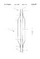
- FIG. 1is a partially sectioned side view of a preferred embodiment of the present invention.
- FIG. 2is a side view of a proximal end of a preferred embodiment of the present invention.
- FIG. 3is a longitudinally sectioned side view of a distal end of a preferred embodiment of the present invention.
- FIG. 4is a cross sectional view taken at A--A in FIG. 1.
- the balloon catheter 10includes an elongate shaft 11 with an inflatable balloon 12 connected at its distal end.
- the balloon 12includes a proximal waist 13 connected to the shaft 11 and a distal waist 14 connected to the formed guide wire tube 25.
- a tip 15is connected to the distal balloon waist 14 and the distal end of the formed guide wire tube 25.
- Radiopaque marker bands 16, 17are secured to the formed guide wire tube 25 and are positioned to designated the working length of the balloon 12.
- a manifold 18is secured to the proximal end of the shaft 11 to facilitate fluid connection to an inflation device and a flush syringe.
- FIG. 2a side view of the preferred embodiment of the manifold 18 is shown.
- the preferred manifold 18is connected to the proximal end of the shaft 11 at hub 22.
- a strain relief 32is placed about the transition from the relatively stiff hub 22 to the relatively flexible shaft 11 and serves to reduce the tendency of the shaft 11 to kink in that area.
- Hub 22serves to separate the inflation lumen 29 and the guide wire lumen 28 (as shown in FIGS. 3 and 4) of the shaft 11 into two distinct tubes; the inflation extension tube 23 and the guide wire extension tube 24.
- An inflation port 19is connected to the proximal end of the inflation extension tube 23 and includes a standard luer adapter for connection to an inflation device (not shown) which are conventional in the art.
- a guide wire port 20is connected to the proximal end of the guide wire extension tube 24 and includes a standard compression o-ring seal to seal about a guide wire.
- a thru port 21is also connected to the proximal end of the guide wire extension tube 24 and includes a standard luer adapter for connection to a conventional syringe or pressure gauge.
- the thru port 21facilitates the injection of contrast dye, the measurement of intravascular pressure, and the flushing of the guide wire lumen 28.
- the combination of the guide wire port 20 and the thru port 21is commonly referred to as a Y-adapter.
- the built-in Y-adapterreduces the number of ancillary devices necessary and simplifies the procedure in contrast to prior art Y-adapters which are separate from the catheter 10.
- the strain relief 32, the inflation extension tube 23 and the guide wire extension tube 24are preferably made of an extruded polyamide/polyether polyester, but those skilled in the art will recognize that other suitable materials and manufacturing processes may be used.
- the inflation port 19, the guide wire port 20 and the thru port 21are formed of injection molded polycarbonate, but other suitable materials and forming processes may be utilized.
- the guide wire extension tube 24, the inflation extension tube 23, the strain relief 32 and the shaft 11are connected together at the hub 32 by an insert molding process. Removable mandrels are used to maintain the inflation lumen 29 and the guide wire lumen 28 (shown in FIGS. 3 and 4) during the insert molding process.
- the hubis preferably made of injection molded polyamide/polyether polyester but other suitable materials may be employed.
- FIG. 3a longitudinally sectioned side view of a distal end of the preferred embodiment of the catheter 10 is shown.
- the balloon 12is connected to the shaft 11 at the proximal waist 13 by a suitable adhesive such as a urethane adhesive available from H. B. Fuller.
- the distal balloon waist 14is bonded to the formed guide wire tube 25 by a suitable adhesive such as a urethane adhesive, but those skilled in the art will recognize that other medical grade adhesives, such as ultraviolet light (UV) curable adhesives may be used, as well as thermal bonds, ultrasonic bonds, etc.
- the balloonis preferably made of extruded and blow molded polyethylene terephthalate, but those skilled in the art will recognize that the balloon can also be made of other materials such as polyethylene, polyolefin copolymer and nylon by conventional blow molding processes.
- the marker bands 16, 17are preferably made of a radiopaque material such as gold, platinum or a platinum alloy (e.g. 90% platinum, 10% iridium). To maintain the correct position on the formed guide wire tube 25, the marker bands 16, 17 are preferably separated by spacer bands, but other securing techniques such as adhesive encapsulating and heat shrink tubing may be employed. In the preferred method, a proximal spacer band is positioned between the proximal marker band 17 and the edge of the skive adjacent the proximal balloon waist 13. A middle spacer band separates the distal marker band 16 from the proximal marker band 17.
- a distal spacer bandseparates the distal marker band 16 from the bond between the distal balloon waist 14 and the formed guide wire tube 25.
- the spacer bandsare preferably made of a polymer. Once in place, the polymer spacers are thermally re-flowed to form a smooth surface and to melt the polymer components together. The smooth surface about the formed guide wire tube 25 reduces the potential for the edges of the marker bands 16, 17 to damage the balloon 12.
- the tip 15is preferably formed integrally with the formed guide wire tube 25 by thermally molding a distal portion of the formed guide wire tube 25 into a cup shape to define a reduced diameter aperture 27.
- the tip 15may be formed integrally with the distal waist 14 of the balloon 12.
- the tip 15can also be a separate component attached to the distal balloon waist 14 or the distal end of the formed guide wire tube 25 by means of a suitable adhesive or thermal bonding process.
- Holes 26are then made by either a drilling or punching process. The holes 26 allow for pressure measurements and dye injections through the guide wire lumen 28 when the guide wire extends through the aperture 27. Two rows of four holes, each hole spaced 90 degrees apart, each hole having a diameter of about 0.017 inches, the rows spaced about 1 millimeter apart, and the rows offset by 45 degrees is preferred.
- the aperture 27remains at about 0.037 inches but is less than the inside diameter of the guide wire lumen 28, preferably about 0.051 inches.
- the tip 15is preferably made of a polyamide/polyether polyester and high density polyethylene blend, but any suitable polymer may be utilized.
- the aperture dimensions and materialmay be altered to effect various performance criteria such as guide wire movement, flow characteristics, etc. Lubricious coating may also be used to improve performance criteria.
- the aperture 27is preferably about 0.018 inches in its relaxed state and can expand to about 0.037 inches to accommodate larger guide wires.
- the tip 15is preferably made of a low durometer polyamide/polyether polyester, but any flexible polymer with compliant characteristics may be utilized.
- the tiputilizes a plurality of longitudinal slits to allow expansion and contraction of the aperture.
- the tipis preferably cone-shaped rather than cup-shaped for this embodiment. With the aperture in the relaxed (contracted) state, the slits are essentially closed. When the aperture expands to accommodate a larger guide wire, the slits open.
- the tipcan utilize a plurality of longitudinal recesses or folds rather than slits. The folds or recesses would function similarly to slits described above.
- holesare formed in the side of the cone-shaped tip to allow for dye injections and pressure measurements when the guide wire extends through the aperture.
- the shaft 11is preferably made of an extruded polyamide/polyether polyester and high density polyethylene blend, but other conventional materials may be used.
- a horizontal membrane 31separates the shaft 11 into separate guide wire lumen 28 and inflation lumens 29.
- the vertical membrane 30serves to prevent the horizontal membrane 31 from collapsing when under pressure.
- the vertical membranemay also serve to isolate an additional lumen which may be used to inject fluids, measure pressures, etc.
- the guide wire lumen 28is sized to allow for pressure measurement and dye injections with a guide wire in place.
- the inflation lumens 29are sized to allow for rapid inflation and deflation of the balloon.
- the extruded shaft 11 of the catheter 12may have an outside diameter of about 0.079 inches, an inside diameter of about 0.065 inches, and a horizontal membrane 31 spaced 0.013 inches off center. Those skilled in the art will recognize that other dimensions may be used to suit the clinical application of the device.
- the catheter shaft 11may include two coaxial tubes in place of a single extrusion.
- the outer tubewould be connected to the proximal end of the balloon and the inner tube would be connected to the distal end of the balloon.
- the manifoldwould be connected to the proximal end of the coaxial tubes in a manner conventional in the art.
- the tipcould be formed integrally with the distal end of the inner tube as discussed earlier.
- the catheter 10incorporates an aperture with a diameter that remains constant (preferably 0.037 inches) but is substantially less than the inner diameter of the guide wire lumen (preferably 0.051 inches) and matches the maximum diameter of the guide wire (typically 0.035 inches), a guide wire is inserted into the vasculature and the balloon catheter 10 is slid over the guide wire.
- the catheter 10may be slid on the guide wire before the guide wire is inserted into the vascular system (referred to as pre-loading), such that the catheter 10 and the guide wire are inserted simultaneously.
- pre-loadingvascular system
- pressure measurements and dye injectionsmay be performed by way of connection to the thru port 21 on the manifold 18.
- the catheter 10is typically used in the following manner. First, a first guide wire is inserted into the vascular system. Second, the balloon catheter 10 with an aperture 27 at its distal end is slid over the first guide wire and the aperture 27 assumes a diameter substantially the same as the diameter of the first guide wire. The catheter 10 may be slid on the guide wire before the guide wire is inserted into the vascular system (referred to as pre-loading), such that the catheter 10 and the guide wire are inserted simultaneously. Third, the first guide wire may be removed from the balloon catheter 10. And fourth, a second guide wire with a different diameter may be inserted into the balloon catheter and the aperture 27 on the balloon catheter 10 changes to a diameter substantially the same as the diameter of the second guide wire. Pressure measurements and dye injections may be performed with a guide wire of a suitable diameter in place by way of connection to the thru port 21 on the manifold 18.
Landscapes
- Health & Medical Sciences (AREA)
- Life Sciences & Earth Sciences (AREA)
- Biophysics (AREA)
- Pulmonology (AREA)
- Engineering & Computer Science (AREA)
- Anesthesiology (AREA)
- Biomedical Technology (AREA)
- Heart & Thoracic Surgery (AREA)
- Hematology (AREA)
- Animal Behavior & Ethology (AREA)
- General Health & Medical Sciences (AREA)
- Public Health (AREA)
- Veterinary Medicine (AREA)
- Media Introduction/Drainage Providing Device (AREA)
Abstract
Description
The present invention generally relates to intravascular catheters. More specifically, the present invention relates to PTA balloon catheters. Those skilled in the art will recognize the benefits of applying the present invention to similar fields not discussed herein.
Intravascular diseases are commonly treated by relatively non-invasive techniques such as percutaneous translumenal angioplasty (PTA) and percutaneous translumenal coronary angioplasty (PTCA). These therapeutic techniques are well known in the art and typically involve the use of a balloon catheter and a guide wire, possibly in combination with other intravascular devices. The balloon catheter is advanced over the guide wire such that the distal end of the balloon catheter is positioned adjacent a restriction in a diseased vessel. The balloon is inflated and the restriction in the vessel is opened, thus restoring normal blood flow.
While many PTCA and PTA devices are well known in the art, PTA has several unique technical and clinical challenges which prior art devices do not overcome. For example, typical PTA guide wire diameters range from about 0.018 inches to about 0.035 inches. The size of the guide wire used may depend on the preference of the physician, the desired vascular site, the morphology of the vasculature, the pressure monitoring capabilities necessary, the dye injection capabilities necessary and/or other device(s) to be used in conjunction with the guide wire. A physician may select or exchange several guide wire and catheter combinations to accommodate the diagnostic and therapeutic requirements of the procedure.
It is generally desirable to have a catheter which is matched to the specific size of the guide wire in use. The word matched in this instance means that the diameter of the distal end of the guide wire is about the same or just slightly less than the diameter of the distal end of the guide wire lumen. Matching the guide wire size to the catheter size avoids scraping, coring or carving vascular tissue when crossing a lesion or entering a puncture site without an introducer sheath. Scraping occurs when a catheter is used with an under-sized guide wire such that a circumferencial ledge is created between the guide wire and the distal of the catheter. The circumferencial ledge tends to scrape, core and carve vascular tissue creating unnecessary damage and increased potential for complications. To avoid these risks, a treating physician can match the catheter and guide wire sizes in order to minimize the circumferencial ledge. However, matching the catheter size to the size of the guide wire compromises the ability of the physician to take pressure measurements or inject contrast dye through the guide wire lumen with the guide wire in place. In addition, changing catheters or guide wires during the procedure increases the time and cost of the procedure. Thus, while a matched guide wire and catheter combination avoids the scraping problem, it increases the required time for a procedure, increases the cost of the procedure, compromises the ability of the physician to take pressure measurements and compromises the ability of the physician to inject contrast dye.
In view of the disadvantages of prior art catheters, it is desirable to have a single catheter which matches the size of a guide wire while maintaining the ability to measure pressure gradients and inject contrast dye with the guide wire in place. Such a catheter would minimize or eliminate the circumferencial ledge and thus minimize the resulting potential for vascular damage. In addition, such a catheter would eliminate the need to change catheters or guide wires and thus reduce the time and cost of the PTA procedure.
The present invention satisfies these desires and overcomes the disadvantages of the prior art in a novel and non-obvious manner. One embodiment of the present invention is a balloon dilation catheter which has a long shaft with an inflatable balloon connected to its distal end. The shaft includes a guide wire lumen which has an inner diameter that is substantially larger than the maximum guide wire diameter used in the procedure. An atraumatic tip is connected to the distal end of the inflatable balloon and includes an aperture which the guide wire passes through. The diameter of the aperture remains constant but is substantially less than the inner diameter of the guide wire lumen and matches the maximum diameter of the guide wire used in the procedure. The atraumatic tip minimizes the potential for vascular damage and eliminates the need to change catheters or guide wires and thus reduces the time and cost of the PTA procedure. The tip also includes holes which allow for dye injection and pressure measurement while the guide wire extends through the aperture.
Another embodiment of the present invention is a balloon dilation catheter which has a long shaft with an inflatable balloon connected to its distal end. A flexible tip is connected to the distal end of the inflatable balloon and includes an aperture which the guide wire passes through. The aperture is compliant such that it can expand or contract to accommodate guide wires of different diameters. The compliant tip minimizes the circumferencial ledge and thereby minimizes the potential for vascular damage. In addition, the compliant tip eliminates the need to change catheters or guide wires and thus reduces the time and cost of the PTA procedure. The tip may also include holes which allow for dye injection and pressure measurement while the guide wire extends through the aperture.
In practice, the first embodiment of the present invention may be used in the following manner. A guide wire is inserted into the vascular system. A balloon catheter is slid over the guide wire either before or after the guide wire is inserted into the vasculature. The catheter includes a guide wire lumen extending therethrough and an aperture located at the distal end of the guide wire lumen. The diameter of the guide wire is substantially less than the inside diameter of the guide wire lumen and is substantially the same as the diameter of the aperture. Dye injections or pressure measurements may be taken through the guide wire lumen with the guide wire in place.
While the disclosure focuses on balloon dilation catheters and methods of use thereof, those skilled in the art will recognize that the invention may be incorporated into other devices and methods of use not discussed herein. Furthermore, in addition to the advantages described, other advantages of the present invention can be appreciated without departing from the spirit of the invention.
FIG. 1 is a partially sectioned side view of a preferred embodiment of the present invention.
FIG. 2 is a side view of a proximal end of a preferred embodiment of the present invention.
FIG. 3 is a longitudinally sectioned side view of a distal end of a preferred embodiment of the present invention.
FIG. 4 is a cross sectional view taken at A--A in FIG. 1.
The following detailed description should be read with reference to the drawings in which like elements in different figures are numbered identically. The materials, dimensions and methods of manufacture are conventional and known in the art unless otherwise specified.
Referring to FIG. 1, a partially sectioned side view of a preferred embodiment of theballoon catheter 10 is shown. Theballoon catheter 10 includes anelongate shaft 11 with aninflatable balloon 12 connected at its distal end. Theballoon 12 includes aproximal waist 13 connected to theshaft 11 and a distal waist 14 connected to the formedguide wire tube 25. Atip 15 is connected to the distal balloon waist 14 and the distal end of the formedguide wire tube 25.Radiopaque marker bands guide wire tube 25 and are positioned to designated the working length of theballoon 12. Amanifold 18 is secured to the proximal end of theshaft 11 to facilitate fluid connection to an inflation device and a flush syringe.
Referring now to FIG. 2, a side view of the preferred embodiment of themanifold 18 is shown. Those skilled in the art will recognize that there are several conventional manifold designs usable with the present invention. Thepreferred manifold 18 is connected to the proximal end of theshaft 11 at hub 22. Astrain relief 32 is placed about the transition from the relatively stiff hub 22 to the relativelyflexible shaft 11 and serves to reduce the tendency of theshaft 11 to kink in that area. Hub 22 serves to separate theinflation lumen 29 and the guide wire lumen 28 (as shown in FIGS. 3 and 4) of theshaft 11 into two distinct tubes; theinflation extension tube 23 and the guidewire extension tube 24. Aninflation port 19 is connected to the proximal end of theinflation extension tube 23 and includes a standard luer adapter for connection to an inflation device (not shown) which are conventional in the art. Aguide wire port 20 is connected to the proximal end of the guidewire extension tube 24 and includes a standard compression o-ring seal to seal about a guide wire. A thruport 21 is also connected to the proximal end of the guidewire extension tube 24 and includes a standard luer adapter for connection to a conventional syringe or pressure gauge. The thruport 21 facilitates the injection of contrast dye, the measurement of intravascular pressure, and the flushing of theguide wire lumen 28. The combination of theguide wire port 20 and the thruport 21 is commonly referred to as a Y-adapter. The built-in Y-adapter reduces the number of ancillary devices necessary and simplifies the procedure in contrast to prior art Y-adapters which are separate from thecatheter 10.
Continuing to refer to FIG. 2, thestrain relief 32, theinflation extension tube 23 and the guidewire extension tube 24 are preferably made of an extruded polyamide/polyether polyester, but those skilled in the art will recognize that other suitable materials and manufacturing processes may be used. Theinflation port 19, theguide wire port 20 and the thruport 21 are formed of injection molded polycarbonate, but other suitable materials and forming processes may be utilized. The guidewire extension tube 24, theinflation extension tube 23, thestrain relief 32 and theshaft 11 are connected together at thehub 32 by an insert molding process. Removable mandrels are used to maintain theinflation lumen 29 and the guide wire lumen 28 (shown in FIGS. 3 and 4) during the insert molding process. The hub is preferably made of injection molded polyamide/polyether polyester but other suitable materials may be employed.
Referring now to FIG. 3, a longitudinally sectioned side view of a distal end of the preferred embodiment of thecatheter 10 is shown. Theballoon 12 is connected to theshaft 11 at theproximal waist 13 by a suitable adhesive such as a urethane adhesive available from H. B. Fuller. Similarly, the distal balloon waist 14 is bonded to the formedguide wire tube 25 by a suitable adhesive such as a urethane adhesive, but those skilled in the art will recognize that other medical grade adhesives, such as ultraviolet light (UV) curable adhesives may be used, as well as thermal bonds, ultrasonic bonds, etc. The balloon is preferably made of extruded and blow molded polyethylene terephthalate, but those skilled in the art will recognize that the balloon can also be made of other materials such as polyethylene, polyolefin copolymer and nylon by conventional blow molding processes.
Continuing to refer to FIG. 3, themarker bands guide wire tube 25, themarker bands proximal marker band 17 and the edge of the skive adjacent theproximal balloon waist 13. A middle spacer band separates thedistal marker band 16 from theproximal marker band 17. A distal spacer band separates thedistal marker band 16 from the bond between the distal balloon waist 14 and the formedguide wire tube 25. The spacer bands are preferably made of a polymer. Once in place, the polymer spacers are thermally re-flowed to form a smooth surface and to melt the polymer components together. The smooth surface about the formedguide wire tube 25 reduces the potential for the edges of themarker bands balloon 12.
With continued reference to FIG. 3, thetip 15 is preferably formed integrally with the formedguide wire tube 25 by thermally molding a distal portion of the formedguide wire tube 25 into a cup shape to define a reduceddiameter aperture 27. Alternatively, thetip 15 may be formed integrally with the distal waist 14 of theballoon 12. Thetip 15 can also be a separate component attached to the distal balloon waist 14 or the distal end of the formedguide wire tube 25 by means of a suitable adhesive or thermal bonding process.Holes 26 are then made by either a drilling or punching process. Theholes 26 allow for pressure measurements and dye injections through theguide wire lumen 28 when the guide wire extends through theaperture 27. Two rows of four holes, each hole spaced 90 degrees apart, each hole having a diameter of about 0.017 inches, the rows spaced about 1 millimeter apart, and the rows offset by 45 degrees is preferred.
In a first embodiment wherein thecatheter 10 is intended for primary use in combination with a guide wire with a diameter of about 0.035 inches, theaperture 27 remains at about 0.037 inches but is less than the inside diameter of theguide wire lumen 28, preferably about 0.051 inches. Thetip 15 is preferably made of a polyamide/polyether polyester and high density polyethylene blend, but any suitable polymer may be utilized. The aperture dimensions and material may be altered to effect various performance criteria such as guide wire movement, flow characteristics, etc. Lubricious coating may also be used to improve performance criteria.
In a second embodiment wherein thecatheter 10 is intended for primary use in combination with a guide wire with a diameter of about 0.018 inches, theaperture 27 is preferably about 0.018 inches in its relaxed state and can expand to about 0.037 inches to accommodate larger guide wires. Thetip 15 is preferably made of a low durometer polyamide/polyether polyester, but any flexible polymer with compliant characteristics may be utilized.
In another embodiment (not shown), the tip utilizes a plurality of longitudinal slits to allow expansion and contraction of the aperture. The tip is preferably cone-shaped rather than cup-shaped for this embodiment. With the aperture in the relaxed (contracted) state, the slits are essentially closed. When the aperture expands to accommodate a larger guide wire, the slits open. Alternatively, the tip can utilize a plurality of longitudinal recesses or folds rather than slits. The folds or recesses would function similarly to slits described above. As in the preferred embodiment, holes are formed in the side of the cone-shaped tip to allow for dye injections and pressure measurements when the guide wire extends through the aperture.
Referring now to FIG. 4, a cross sectional view of theshaft 11 is shown (taken at A--A in FIG. 1). The shaft is preferably made of an extruded polyamide/polyether polyester and high density polyethylene blend, but other conventional materials may be used. Ahorizontal membrane 31 separates theshaft 11 into separateguide wire lumen 28 andinflation lumens 29. Thevertical membrane 30 serves to prevent thehorizontal membrane 31 from collapsing when under pressure. The vertical membrane may also serve to isolate an additional lumen which may be used to inject fluids, measure pressures, etc. In the preferred embodiment, theguide wire lumen 28 is sized to allow for pressure measurement and dye injections with a guide wire in place. Theinflation lumens 29 are sized to allow for rapid inflation and deflation of the balloon. In a first embodiment, the extrudedshaft 11 of thecatheter 12 may have an outside diameter of about 0.079 inches, an inside diameter of about 0.065 inches, and ahorizontal membrane 31 spaced 0.013 inches off center. Those skilled in the art will recognize that other dimensions may be used to suit the clinical application of the device.
In an alternative embodiment (not shown), thecatheter shaft 11 may include two coaxial tubes in place of a single extrusion. In this embodiment, the outer tube would be connected to the proximal end of the balloon and the inner tube would be connected to the distal end of the balloon. The manifold would be connected to the proximal end of the coaxial tubes in a manner conventional in the art. The tip could be formed integrally with the distal end of the inner tube as discussed earlier.
In practice the catheter may be used in the following manner. Thecatheter 10 incorporates an aperture with a diameter that remains constant (preferably 0.037 inches) but is substantially less than the inner diameter of the guide wire lumen (preferably 0.051 inches) and matches the maximum diameter of the guide wire (typically 0.035 inches), a guide wire is inserted into the vasculature and theballoon catheter 10 is slid over the guide wire. Thecatheter 10 may be slid on the guide wire before the guide wire is inserted into the vascular system (referred to as pre-loading), such that thecatheter 10 and the guide wire are inserted simultaneously. While the guide wire remains inside thecatheter 10, pressure measurements and dye injections may be performed by way of connection to the thruport 21 on themanifold 18. In this alternative use and specified dimensions, laboratory tests have shown that flow rates of about 2.25 cc/sec are easily achieved with a 0.035 inch diameter guide wire in place (60 psi inlet pressure, 50/50 mix of saline and Renografin 76 contrast dye, 75 cm catheter length).
In an alternative use, thecatheter 10 is typically used in the following manner. First, a first guide wire is inserted into the vascular system. Second, theballoon catheter 10 with anaperture 27 at its distal end is slid over the first guide wire and theaperture 27 assumes a diameter substantially the same as the diameter of the first guide wire. Thecatheter 10 may be slid on the guide wire before the guide wire is inserted into the vascular system (referred to as pre-loading), such that thecatheter 10 and the guide wire are inserted simultaneously. Third, the first guide wire may be removed from theballoon catheter 10. And fourth, a second guide wire with a different diameter may be inserted into the balloon catheter and theaperture 27 on theballoon catheter 10 changes to a diameter substantially the same as the diameter of the second guide wire. Pressure measurements and dye injections may be performed with a guide wire of a suitable diameter in place by way of connection to the thruport 21 on themanifold 18.
While the specification describes the preferred constructions, materials, methods of manufacture and methods of practice, those skilled in the art will appreciate the scope and spirit of the invention with reference to the appended claims.
Claims (18)
1. A balloon dilation catheter system, comprising:
(i) a guide wire; and
(ii) a balloon dilation catheter removably disposed about the guide wire, the balloon catheter comprising:
(a) an elongate shaft having a proximal end and a distal end, the elongate shaft defining a guide wire lumen and an inflation lumen extending therethrough, the guide wire lumen having an inside diameter;
(b) an inflatable balloon connected to the distal end of the elongate shaft, the inflatable balloon having a proximal end, a distal end and an interior in fluid communication with the inflation lumen, the guide wire lumen extending through the balloon; and
(c) a tip connected to the distal end of the inflatable balloon, the tip defining a plurality of laterally-facing holes and a distally-facing guide wire aperture, the distally-facing guide wire aperture having a diameter less than the inside diameter of the guide wire lumen, both the distally-facing guide wire aperture and the laterally-facing holes being in fluid communication with the guide wire lumen, wherein the guide wire lumen defines a continuously sealed fluid path between the proximal end of the shaft and the laterally-facing holes such that fluid injected into the guide wire lumen exits distally of the balloon through the laterally-facing holes.
2. A dilation catheter as in claim 1, wherein the holes are radially spaced.
3. A dilation catheter as in claim 1, wherein the holes are longitudinally spaced.
4. A dilation catheter as in claim 1, wherein the holes are radially and longitudinally spaced.
5. A dilation catheter as in claim 1, wherein the tip is formed integrally with the distal end of the elongate shaft.
6. A dilation catheter as in claim 1, wherein the tip is formed integrally with the distal end of the balloon.
7. A dilation catheter as in claim 1, wherein the inside diameter of the guide wire lumen is greater than 0.040 inches.
8. A dilation catheter as in claim 7, wherein the diameter of the aperture is less than 0.038 inches.
9. A balloon dilation catheter system, comprising:
(i) a guide wire; and
(ii) a balloon dilation catheter removably disposed about the guide wire, the balloon catheter comprising:
(a) an elongate shaft having a proximal end and a distal end, the elongate shaft defining a guide wire lumen and an inflation lumen extending therethrough;
(b) an inflatable balloon connected to the distal end of the elongate shaft, the inflatable balloon having a proximal end, a distal end and an interior in fluid communication with the inflation lumen, the guide wire lumen extending through the balloon; and
(c) a tip connected to the distal end of the inflatable balloon, the tip defining a distally-facing radially compliant guide wire aperture and a plurality of laterally-facing holes, both the distally-facing radially compliant guide wire aperture and the laterally-facing holes being in fluid communication with the guide wire lumen, wherein the guide wire lumen defines a continuously sealed fluid path between the proximal end of the shaft and the laterally-facing holes such that fluid injected into the guide wire lumen exits distally of the balloon through the laterally-facing holes.
10. A dilation catheter as in claim 9, where in the holes are radially spaced.
11. A dilation catheter as in claim 9, wherein the holes are longitudinally spaced.
12. A dilation catheter as in claim 9, wherein the holes are radially and longitudinally spaced.
13. A dilation catheter as in claim 12, wherein the holes measure about 0.010 inches to about 0.020 inches in diameter and total about 4 to 10 in quantity.
14. A balloon dilation catheter system comprising:
(i) a guide wire having an outside diameter; and
(ii) a balloon dilation catheter removably disposed about the guide wire, the balloon catheter comprising:
(a) an elongate shaft having a proximal end and a distal end, the elongate shaft defining a guide wire lumen and an inflation lumen extending therethrough;
(b) an inflatable balloon connected to the distal end of the elongate shaft, the inflatable balloon having a proximal end, a distal end and an interior in fluid communication with the inflation lumen, the guide wire lumen extending through the balloon; and
(c) a tip connected to the distal end of the inflatable balloon, the tip defining a distally-facing radially compliant guide wire aperture and a plurality of laterally-facing holes, the distally-facing radially compliant guide wire aperture having a relaxed diameter less than the outside diameter of the removable guide wire, both the distally-facing radially compliant guide wire aperture and the laterally-facing holes being in fluid communication with the guide wire lumen, wherein the guide wire lumen defines a continuously sealed fluid path between the proximal end of the shaft and the laterally-facing holes such that fluid injected into the guide wire lumen exits distally of the balloon through the laterally-facing holes.
15. A dilation catheter system as in claim 14, wherein the tip of the dilation catheter is cup-shaped.
16. A dilation catheter system as in claim 14, wherein the tip of the dilation catheter is conically-shaped.
17. A dilation catheter system as in claim 14, wherein the tip of the dilation catheter includes a plurality of longitudinal slits extending through the tip.
18. A dilation catheter system as in claim 14, wherein the tip of the dilation catheter includes a plurality of longitudinal recesses extending through the tip.
Priority Applications (1)
| Application Number | Priority Date | Filing Date | Title |
|---|---|---|---|
| US08/274,071US5921957A (en) | 1994-07-12 | 1994-07-12 | Intravascular dilation catheter |
Applications Claiming Priority (1)
| Application Number | Priority Date | Filing Date | Title |
|---|---|---|---|
| US08/274,071US5921957A (en) | 1994-07-12 | 1994-07-12 | Intravascular dilation catheter |
Publications (1)
| Publication Number | Publication Date |
|---|---|
| US5921957Atrue US5921957A (en) | 1999-07-13 |
Family
ID=23046634
Family Applications (1)
| Application Number | Title | Priority Date | Filing Date |
|---|---|---|---|
| US08/274,071Expired - Fee RelatedUS5921957A (en) | 1994-07-12 | 1994-07-12 | Intravascular dilation catheter |
Country Status (1)
| Country | Link |
|---|---|
| US (1) | US5921957A (en) |
Cited By (74)
| Publication number | Priority date | Publication date | Assignee | Title |
|---|---|---|---|---|
| US6146356A (en)* | 1994-03-02 | 2000-11-14 | Scimed Life Systems, Inc. | Block copolymer elastomer catheter balloons |
| US6165158A (en)* | 1998-10-14 | 2000-12-26 | Advanced Cardiovascular Systems, Inc. | Lubricious catheter shaft |
| US6200290B1 (en)* | 1995-05-24 | 2001-03-13 | Schneider (Usa) Inc. | Dilatation balloons containing polyesteretheramide copolymer |
| USD466607S1 (en) | 2001-08-27 | 2002-12-03 | Kimberly-Clark Worldwide, Inc. | Flexible connector |
| WO2003000334A1 (en)* | 2001-06-26 | 2003-01-03 | Concentric Medical, Inc. | Balloon catheter |
| US20030069523A1 (en)* | 2001-09-10 | 2003-04-10 | Williams John Vaughan | Catheter positioning device |
| US6547768B2 (en) | 2000-12-14 | 2003-04-15 | Cordis Corporation | Medical devices with reduced friction polyamides, and method |
| USD473941S1 (en) | 2001-08-27 | 2003-04-29 | Kimberly-Clark Worldwide, Inc. | Flexible connecting device |
| US20030120206A1 (en)* | 2001-12-21 | 2003-06-26 | Cartledge Richard G. | Balloon cannulae |
| USD476731S1 (en) | 2001-08-27 | 2003-07-01 | Kimberly-Clark Worldwide, Inc. | Bendable connector |
| USD486909S1 (en) | 2001-08-27 | 2004-02-17 | Kimberly-Clark Worldwide, Inc. | Bendable connecting device |
| US6702782B2 (en)* | 2001-06-26 | 2004-03-09 | Concentric Medical, Inc. | Large lumen balloon catheter |
| US6706010B1 (en)* | 1997-10-08 | 2004-03-16 | Kaneka Corporation | Balloon catheter and method of production thereof |
| US20040143261A1 (en)* | 2003-01-21 | 2004-07-22 | Hartley Amanda April | Surgical device with pressure monitoring ability |
| US20040143262A1 (en)* | 2003-01-21 | 2004-07-22 | Baylis Medical Company Inc. | Surgical perforation device and method with pressure monitoring and staining abilities |
| US6855154B2 (en) | 2000-08-11 | 2005-02-15 | University Of Louisville Research Foundation, Inc. | Endovascular aneurysm treatment device and method |
| US20050065507A1 (en)* | 2003-09-19 | 2005-03-24 | Baylis Medical Company Inc. | Surgical perforation device with curve |
| US20050197667A1 (en)* | 2004-03-02 | 2005-09-08 | Scimed Life Systems, Inc. | Occlusion balloon catheter with external inflation lumen |
| US20060142756A1 (en)* | 2003-01-21 | 2006-06-29 | Baylis Medical Company Inc. | Method of surgical perforation via the delivery of energy |
| US20060151923A1 (en)* | 2005-01-10 | 2006-07-13 | Wilkowske Eric J | Steerable catheter and methods of making the same |
| US20060247575A1 (en)* | 2001-12-21 | 2006-11-02 | Richard Cartledge | Balloon cannulae |
| US7163522B1 (en)* | 1994-03-02 | 2007-01-16 | Scimed Life Systems, Inc. | Block copolymer elastomer catheter balloons |
| US7172608B2 (en) | 1999-05-18 | 2007-02-06 | Cardica, Inc. | Sutureless closure and deployment system for connecting blood vessels |
| US20070073271A1 (en)* | 2003-11-15 | 2007-03-29 | Brucker Gregory G | Catheter for diagnostic imaging and therapeutic procedures |
| US20070129704A1 (en)* | 2003-12-02 | 2007-06-07 | O'mahony John J | Method and apparatus for ultrafiltration utilizing a peripheral access dual lumen venous cannula |
| US7309343B2 (en) | 1999-05-18 | 2007-12-18 | Cardica, Inc. | Method for cutting tissue |
| US7357807B2 (en)* | 1999-05-18 | 2008-04-15 | Cardica, Inc. | Integrated anastomosis tool with graft vessel attachment device and cutting device |
| US20080097339A1 (en)* | 2006-08-31 | 2008-04-24 | Medrad, Inc. | Catheter with filtering and sensing elements |
| EP1547537A4 (en)* | 2002-08-20 | 2009-04-29 | Toray Industries | Catheter for treating irregular heart pulse |
| US7749585B2 (en) | 1996-10-08 | 2010-07-06 | Alan Zamore | Reduced profile medical balloon element |
| US20100198186A1 (en)* | 2009-02-03 | 2010-08-05 | Ackermann Simon | Dual-lumen catheter for medical device delivery systems |
| US20110224666A1 (en)* | 2003-01-21 | 2011-09-15 | Gareth Davies | Method of surgical perforation via the delivery of energy |
| US20140277064A1 (en)* | 2013-03-15 | 2014-09-18 | Rsh, Llc | Multi-lumen shaft used with endoscopic device |
| US20180169391A1 (en)* | 2008-11-19 | 2018-06-21 | Nexstep Medical | Angioplasty device |
| US10028745B2 (en) | 2011-03-30 | 2018-07-24 | Noha, Llc | Advanced endovascular clip and method of using same |
| US10398444B2 (en) | 2011-03-30 | 2019-09-03 | Noha, Llc | Advanced endovascular clip and method of using same |
| US20200188633A1 (en)* | 2014-11-04 | 2020-06-18 | Orbusneich Medical Pte. Ltd. | Progressive flexibility catheter support frame |
| EP2967600B1 (en)* | 2013-03-15 | 2020-07-15 | Rsh Llc | Removal tool for use with endoscopic device |
| US11660137B2 (en) | 2006-09-29 | 2023-05-30 | Boston Scientific Medical Device Limited | Connector system for electrosurgical device |
| US11684447B2 (en) | 2012-05-31 | 2023-06-27 | Boston Scientific Medical Device Limited | Radiofrequency perforation apparatus |
| US11724070B2 (en) | 2019-12-19 | 2023-08-15 | Boston Scientific Medical Device Limited | Methods for determining a position of a first medical device with respect to a second medical device, and related systems and medical devices |
| US11744638B2 (en) | 2006-09-29 | 2023-09-05 | Boston Scientific Medical Device Limited | Electrosurgical device |
| US11744988B2 (en) | 2014-11-04 | 2023-09-05 | Orbusneich Medical Pte. Ltd. | Variable flexibility catheter support frame |
| US11759190B2 (en) | 2019-10-18 | 2023-09-19 | Boston Scientific Medical Device Limited | Lock for medical devices, and related systems and methods |
| US11766290B2 (en) | 2015-09-09 | 2023-09-26 | Boston Scientific Medical Device Limited | Epicardial access system and methods |
| US11793446B2 (en) | 2020-06-17 | 2023-10-24 | Boston Scientific Medical Device Limited | Electroanatomical mapping system with visualization of energy-delivery and elongated needle assemblies |
| US11801087B2 (en) | 2019-11-13 | 2023-10-31 | Boston Scientific Medical Device Limited | Apparatus and methods for puncturing tissue |
| US11819243B2 (en) | 2020-03-19 | 2023-11-21 | Boston Scientific Medical Device Limited | Medical sheath and related systems and methods |
| US11826075B2 (en) | 2020-04-07 | 2023-11-28 | Boston Scientific Medical Device Limited | Elongated medical assembly |
| US11878131B2 (en) | 2017-12-05 | 2024-01-23 | Boston Scientific Medical Device Limited | Transseptal guide wire puncture system |
| US11931098B2 (en) | 2020-02-19 | 2024-03-19 | Boston Scientific Medical Device Limited | System and method for carrying out a medical procedure |
| US11937796B2 (en) | 2020-06-18 | 2024-03-26 | Boston Scientific Medical Device Limited | Tissue-spreader assembly |
| US11938285B2 (en) | 2020-06-17 | 2024-03-26 | Boston Scientific Medical Device Limited | Stop-movement device for elongated medical assembly |
| US11937873B2 (en) | 2013-03-12 | 2024-03-26 | Boston Scientific Medical Device Limited | Electrosurgical device having a lumen |
| US11980412B2 (en) | 2020-09-15 | 2024-05-14 | Boston Scientific Medical Device Limited | Elongated medical sheath |
| US11986209B2 (en) | 2020-02-25 | 2024-05-21 | Boston Scientific Medical Device Limited | Methods and devices for creation of communication between aorta and left atrium |
| US11998238B2 (en) | 2013-08-07 | 2024-06-04 | Boston Scientific Medical Device Limited | Methods and devices for puncturing tissue |
| US12005202B2 (en) | 2020-08-07 | 2024-06-11 | Boston Scientific Medical Device Limited | Catheter having tissue-engaging device |
| US12011279B2 (en) | 2020-04-07 | 2024-06-18 | Boston Scientific Medical Device Limited | Electro-anatomic mapping system |
| US12011210B2 (en) | 2013-03-15 | 2024-06-18 | Boston Scientific Medical Device Limited | Electrosurgical device having a distal aperture |
| US12042178B2 (en) | 2020-07-21 | 2024-07-23 | Boston Scientific Medical Device Limited | System of medical devices and method for pericardial puncture |
| US12082792B2 (en) | 2020-02-25 | 2024-09-10 | Boston Scientific Medical Device Limited | Systems and methods for creating a puncture between aorta and the left atrium |
| US12128199B2 (en) | 2016-01-07 | 2024-10-29 | Boston Scientific Medical Device Limited | Hybrid transseptal dilator and methods of using the same |
| US12156642B2 (en) | 2019-04-29 | 2024-12-03 | Boston Scientific Medical Device Limited | Transseptal systems, devices and methods |
| US12171622B2 (en) | 2017-08-10 | 2024-12-24 | Boston Scientific Medical Device Limited | Heat exchange and temperature sensing device and method of use |
| US12207836B2 (en) | 2016-11-01 | 2025-01-28 | Boston Scientific Medical Device Limited | Methods and devices for puncturing tissue |
| US12220543B2 (en) | 2020-09-10 | 2025-02-11 | Boston Scientific Medical Device Limited | Elongated medical catheter including marker band |
| US12251159B2 (en) | 2013-03-12 | 2025-03-18 | Boston Scientific Medical Device Limited | Medical device having a support structure |
| US12257401B2 (en) | 2013-12-20 | 2025-03-25 | Boston Scientific Medical Device Limited | Steerable medical device handle |
| US12343042B2 (en) | 2020-07-16 | 2025-07-01 | Boston Scientific Medical Device Limited | Pericardial puncture device and method |
| US12370354B2 (en) | 2018-05-08 | 2025-07-29 | Boston Scientific Medical Device Limited | Coupling mechanisms for medical devices |
| US12396785B2 (en) | 2020-08-12 | 2025-08-26 | Boston Scientific Medical Device Limited | System of medical devices and method for pericardial puncture |
| US12420067B2 (en) | 2020-05-12 | 2025-09-23 | Boston Scientific Medical Device Limited | Guidewire assembly |
| US12440266B2 (en) | 2022-04-08 | 2025-10-14 | Boston Scientific Medical Device Limited | Transvascular electrosurgical devices and systems and methods of using the same |
Citations (60)
| Publication number | Priority date | Publication date | Assignee | Title |
|---|---|---|---|---|
| US2667875A (en)* | 1951-03-30 | 1954-02-02 | American Cystoscope Makers Inc | Inflatable retention catheter |
| US3828767A (en)* | 1973-10-29 | 1974-08-13 | Fenton J | Angiographic and arteriographic catherters |
| US4114625A (en)* | 1976-12-02 | 1978-09-19 | Onat Mustafa V | Anti-vomiting, anti-aspirating oral-nasal gastric tube |
| US4214593A (en)* | 1978-09-18 | 1980-07-29 | Mallinckrodt, Inc. | Esophageal pressure monitoring device |
| US4323071A (en)* | 1978-04-24 | 1982-04-06 | Advanced Catheter Systems, Inc. | Vascular guiding catheter assembly and vascular dilating catheter assembly and a combination thereof and methods of making the same |
| US4361152A (en)* | 1975-05-27 | 1982-11-30 | The Kendall Company | Catheter |
| US4464176A (en)* | 1982-06-04 | 1984-08-07 | Mallinckrodt, Inc. | Blood vessel catheter for medicine delivery and method of manufacture |
| US4571240A (en)* | 1983-08-12 | 1986-02-18 | Advanced Cardiovascular Systems, Inc. | Catheter having encapsulated tip marker |
| US4588398A (en)* | 1984-09-12 | 1986-05-13 | Warner-Lambert Company | Catheter tip configuration |
| US4597755A (en)* | 1984-05-30 | 1986-07-01 | Advanced Cardiovascular Systems, Inc. | Large bore catheter having flexible tip construction |
| US4606347A (en)* | 1983-03-25 | 1986-08-19 | Thomas J. Fogarty | Inverted balloon catheter having sealed through lumen |
| US4638805A (en)* | 1985-07-30 | 1987-01-27 | Advanced Cardiovascular Systems, Inc. | Self-venting balloon dilatation catheter and method |
| US4641654A (en)* | 1985-07-30 | 1987-02-10 | Advanced Cardiovascular Systems, Inc. | Steerable balloon dilatation catheter assembly having dye injection and pressure measurement capabilities |
| US4670009A (en)* | 1985-04-16 | 1987-06-02 | American Hospital Supply Corp. | Backform inserts for catheter |
| US4684323A (en)* | 1985-12-23 | 1987-08-04 | United Technologies Corporation | Film cooling passages with curved corners |
| US4723556A (en)* | 1986-04-14 | 1988-02-09 | Cordis Corporation | Intracranial ventricular catheter assembly |
| US4752286A (en)* | 1984-12-19 | 1988-06-21 | Sherwood Medical Company | Balloon tube for treating esophagus varix |
| US4775371A (en)* | 1986-09-02 | 1988-10-04 | Advanced Cardiovascular Systems, Inc. | Stiffened dilatation catheter and method of manufacture |
| US4782834A (en)* | 1987-01-06 | 1988-11-08 | Advanced Cardiovascular Systems, Inc. | Dual lumen dilatation catheter and method of manufacturing the same |
| US4793351A (en)* | 1987-06-15 | 1988-12-27 | Mansfield Scientific, Inc. | Multi-lumen balloon catheter |
| US4813934A (en)* | 1987-08-07 | 1989-03-21 | Target Therapeutics | Valved catheter device and method |
| US4848344A (en)* | 1987-11-13 | 1989-07-18 | Cook, Inc. | Balloon guide |
| US4850969A (en)* | 1987-10-01 | 1989-07-25 | Retroperfusion Systems, Inc. | Retroperfusion catheter and tip construction for use therewith |
| US4892519A (en)* | 1987-12-03 | 1990-01-09 | Advanced Cardiovascular Systems, Inc. | Steerable perfusion dilatation catheter |
| US4909258A (en)* | 1988-08-08 | 1990-03-20 | The Beth Israel Hospital Association | Internal mammary artery (IMA) catheter |
| US4917666A (en)* | 1988-11-14 | 1990-04-17 | Medtronic Versaflex, Inc. | Steerable thru-lumen catheter |
| US4921483A (en)* | 1985-12-19 | 1990-05-01 | Leocor, Inc. | Angioplasty catheter |
| US4927418A (en)* | 1989-01-09 | 1990-05-22 | Advanced Cardiovascular Systems, Inc. | Catheter for uniform distribution of therapeutic fluids |
| US4932959A (en)* | 1988-12-01 | 1990-06-12 | Advanced Cardiovascular Systems, Inc. | Vascular catheter with releasably secured guidewire |
| US4955895A (en)* | 1986-12-23 | 1990-09-11 | Terumo Kabushiki Kaisha | Vasodilating catheter |
| US4964853A (en)* | 1987-02-27 | 1990-10-23 | Terumo Kabushiki Kaisha | Catheter equipped with expansible member |
| US4995865A (en)* | 1989-06-09 | 1991-02-26 | Worldwide Medical Plastics Inc. | Multi-lumen catheters |
| US5015232A (en)* | 1989-04-20 | 1991-05-14 | Cook Incorporated | Decompression enteroclysis balloon catheter |
| US5021045A (en)* | 1988-04-28 | 1991-06-04 | Research Medical, Inc. | Retrograde venous cardioplegia catheters and methods of use and manufacture |
| US5021044A (en)* | 1989-01-30 | 1991-06-04 | Advanced Cardiovascular Systems, Inc. | Catheter for even distribution of therapeutic fluids |
| US5035694A (en)* | 1989-05-15 | 1991-07-30 | Advanced Cardiovascular Systems, Inc. | Dilatation catheter assembly with heated balloon |
| US5041083A (en)* | 1987-06-25 | 1991-08-20 | Terumo Kabushiki Kaisha | Multi-luminal catheter, multi-luminal catheter assembly |
| US5053004A (en)* | 1990-08-24 | 1991-10-01 | Medical Components, Inc. | Catheter having two coaxial lumens |
| US5059176A (en)* | 1989-12-21 | 1991-10-22 | Winters R Edward | Vascular system steerable guidewire with inflatable balloon |
| US5078681A (en)* | 1989-10-23 | 1992-01-07 | Olympus Optical Co., Ltd. | Balloon catheter apparatus with releasable distal seal and method of operation |
| US5085636A (en)* | 1989-01-13 | 1992-02-04 | Scimed Life Systems, Inc. | Balloon catheter with inflation-deflation valve |
| US5085635A (en)* | 1990-05-18 | 1992-02-04 | Cragg Andrew H | Valved-tip angiographic catheter |
| US5114423A (en)* | 1989-05-15 | 1992-05-19 | Advanced Cardiovascular Systems, Inc. | Dilatation catheter assembly with heated balloon |
| US5135599A (en)* | 1987-12-22 | 1992-08-04 | Vas-Cath Incorporated | Method of making a triple lumen catheter |
| US5135494A (en)* | 1988-08-01 | 1992-08-04 | Target Therapeutics | Valved catheter device and method |
| US5141518A (en)* | 1991-03-05 | 1992-08-25 | Progressive Angioplasty Systems, Inc. | Angioplasty catheter with close-fitting guidewire and tube |
| US5147385A (en)* | 1989-11-01 | 1992-09-15 | Schneider (Europe) A.G. | Stent and catheter for the introduction of the stent |
| US5171221A (en)* | 1991-02-05 | 1992-12-15 | Target Therapeutics | Single lumen low profile valved balloon catheter |
| US5176661A (en)* | 1988-09-06 | 1993-01-05 | Advanced Cardiovascular Systems, Inc. | Composite vascular catheter |
| US5188593A (en)* | 1988-04-21 | 1993-02-23 | Vas-Cath Incorporated | Dual lumen catheter |
| US5195971A (en)* | 1992-02-10 | 1993-03-23 | Advanced Cardiovascular Systems, Inc. | Perfusion type dilatation catheter |
| US5197948A (en)* | 1991-01-03 | 1993-03-30 | Kamran Ghodsian | Intra-abdominal organ manipulator, irrigator and aspirator |
| US5197951A (en)* | 1983-12-14 | 1993-03-30 | Mahurkar Sakharam D | Simple double lumen catheter |
| US5209729A (en)* | 1990-08-09 | 1993-05-11 | Schneider (Europe) Ag | Dilatation catheter |
| US5221256A (en)* | 1992-02-10 | 1993-06-22 | Mahurkar Sakharam D | Multiple-lumen catheter |
| US5242396A (en)* | 1991-12-19 | 1993-09-07 | Advanced Cardiovascular Systems, Inc. | Dilatation catheter with reinforcing mandrel |
| US5250069A (en)* | 1987-02-27 | 1993-10-05 | Terumo Kabushiki Kaisha | Catheter equipped with expansible member and production method thereof |
| US5250034A (en)* | 1990-09-17 | 1993-10-05 | E-Z-Em, Inc. | Pressure responsive valve catheter |
| US5295961A (en)* | 1991-06-03 | 1994-03-22 | Schneider (Europe) A.G. | Catheter system for mechanical dilatation of coronary stenoses |
| US5308323A (en)* | 1988-06-06 | 1994-05-03 | Sumitomo Electric Industries. Ltd. | Multiple compartment balloon catheter |
- 1994
- 1994-07-12USUS08/274,071patent/US5921957A/ennot_activeExpired - Fee Related
Patent Citations (63)
| Publication number | Priority date | Publication date | Assignee | Title |
|---|---|---|---|---|
| US2667875A (en)* | 1951-03-30 | 1954-02-02 | American Cystoscope Makers Inc | Inflatable retention catheter |
| US3828767A (en)* | 1973-10-29 | 1974-08-13 | Fenton J | Angiographic and arteriographic catherters |
| US4361152A (en)* | 1975-05-27 | 1982-11-30 | The Kendall Company | Catheter |
| US4114625A (en)* | 1976-12-02 | 1978-09-19 | Onat Mustafa V | Anti-vomiting, anti-aspirating oral-nasal gastric tube |
| US4323071A (en)* | 1978-04-24 | 1982-04-06 | Advanced Catheter Systems, Inc. | Vascular guiding catheter assembly and vascular dilating catheter assembly and a combination thereof and methods of making the same |
| US4323071B1 (en)* | 1978-04-24 | 1990-05-29 | Advanced Cardiovascular System | |
| US4214593A (en)* | 1978-09-18 | 1980-07-29 | Mallinckrodt, Inc. | Esophageal pressure monitoring device |
| US4464176A (en)* | 1982-06-04 | 1984-08-07 | Mallinckrodt, Inc. | Blood vessel catheter for medicine delivery and method of manufacture |
| US4606347A (en)* | 1983-03-25 | 1986-08-19 | Thomas J. Fogarty | Inverted balloon catheter having sealed through lumen |
| US4571240A (en)* | 1983-08-12 | 1986-02-18 | Advanced Cardiovascular Systems, Inc. | Catheter having encapsulated tip marker |
| US5197951A (en)* | 1983-12-14 | 1993-03-30 | Mahurkar Sakharam D | Simple double lumen catheter |
| US4597755A (en)* | 1984-05-30 | 1986-07-01 | Advanced Cardiovascular Systems, Inc. | Large bore catheter having flexible tip construction |
| US4588398A (en)* | 1984-09-12 | 1986-05-13 | Warner-Lambert Company | Catheter tip configuration |
| US4752286A (en)* | 1984-12-19 | 1988-06-21 | Sherwood Medical Company | Balloon tube for treating esophagus varix |
| US4670009A (en)* | 1985-04-16 | 1987-06-02 | American Hospital Supply Corp. | Backform inserts for catheter |
| US4638805A (en)* | 1985-07-30 | 1987-01-27 | Advanced Cardiovascular Systems, Inc. | Self-venting balloon dilatation catheter and method |
| US4641654A (en)* | 1985-07-30 | 1987-02-10 | Advanced Cardiovascular Systems, Inc. | Steerable balloon dilatation catheter assembly having dye injection and pressure measurement capabilities |
| US4921483A (en)* | 1985-12-19 | 1990-05-01 | Leocor, Inc. | Angioplasty catheter |
| US4684323A (en)* | 1985-12-23 | 1987-08-04 | United Technologies Corporation | Film cooling passages with curved corners |
| US4723556A (en)* | 1986-04-14 | 1988-02-09 | Cordis Corporation | Intracranial ventricular catheter assembly |
| US4775371A (en)* | 1986-09-02 | 1988-10-04 | Advanced Cardiovascular Systems, Inc. | Stiffened dilatation catheter and method of manufacture |
| US4955895A (en)* | 1986-12-23 | 1990-09-11 | Terumo Kabushiki Kaisha | Vasodilating catheter |
| US4782834A (en)* | 1987-01-06 | 1988-11-08 | Advanced Cardiovascular Systems, Inc. | Dual lumen dilatation catheter and method of manufacturing the same |
| US4964853A (en)* | 1987-02-27 | 1990-10-23 | Terumo Kabushiki Kaisha | Catheter equipped with expansible member |
| US5250069A (en)* | 1987-02-27 | 1993-10-05 | Terumo Kabushiki Kaisha | Catheter equipped with expansible member and production method thereof |
| US4793351A (en)* | 1987-06-15 | 1988-12-27 | Mansfield Scientific, Inc. | Multi-lumen balloon catheter |
| US5041083A (en)* | 1987-06-25 | 1991-08-20 | Terumo Kabushiki Kaisha | Multi-luminal catheter, multi-luminal catheter assembly |
| US4813934B1 (en)* | 1987-08-07 | 1992-05-12 | Target Therapeutics Inc | |
| US4813934A (en)* | 1987-08-07 | 1989-03-21 | Target Therapeutics | Valved catheter device and method |
| US4850969A (en)* | 1987-10-01 | 1989-07-25 | Retroperfusion Systems, Inc. | Retroperfusion catheter and tip construction for use therewith |
| US4848344A (en)* | 1987-11-13 | 1989-07-18 | Cook, Inc. | Balloon guide |
| US4892519A (en)* | 1987-12-03 | 1990-01-09 | Advanced Cardiovascular Systems, Inc. | Steerable perfusion dilatation catheter |
| US5135599A (en)* | 1987-12-22 | 1992-08-04 | Vas-Cath Incorporated | Method of making a triple lumen catheter |
| US5188593A (en)* | 1988-04-21 | 1993-02-23 | Vas-Cath Incorporated | Dual lumen catheter |
| US5021045A (en)* | 1988-04-28 | 1991-06-04 | Research Medical, Inc. | Retrograde venous cardioplegia catheters and methods of use and manufacture |
| US5308323A (en)* | 1988-06-06 | 1994-05-03 | Sumitomo Electric Industries. Ltd. | Multiple compartment balloon catheter |
| US5135494A (en)* | 1988-08-01 | 1992-08-04 | Target Therapeutics | Valved catheter device and method |
| US4909258A (en)* | 1988-08-08 | 1990-03-20 | The Beth Israel Hospital Association | Internal mammary artery (IMA) catheter |
| US5176661A (en)* | 1988-09-06 | 1993-01-05 | Advanced Cardiovascular Systems, Inc. | Composite vascular catheter |
| US4917666A (en)* | 1988-11-14 | 1990-04-17 | Medtronic Versaflex, Inc. | Steerable thru-lumen catheter |
| US4932959A (en)* | 1988-12-01 | 1990-06-12 | Advanced Cardiovascular Systems, Inc. | Vascular catheter with releasably secured guidewire |
| US4927418A (en)* | 1989-01-09 | 1990-05-22 | Advanced Cardiovascular Systems, Inc. | Catheter for uniform distribution of therapeutic fluids |
| US5085636A (en)* | 1989-01-13 | 1992-02-04 | Scimed Life Systems, Inc. | Balloon catheter with inflation-deflation valve |
| US5021044A (en)* | 1989-01-30 | 1991-06-04 | Advanced Cardiovascular Systems, Inc. | Catheter for even distribution of therapeutic fluids |
| US5015232A (en)* | 1989-04-20 | 1991-05-14 | Cook Incorporated | Decompression enteroclysis balloon catheter |
| US5242395A (en)* | 1989-04-20 | 1993-09-07 | Cook Incorporated | Balloon decompression catheter |
| US5114423A (en)* | 1989-05-15 | 1992-05-19 | Advanced Cardiovascular Systems, Inc. | Dilatation catheter assembly with heated balloon |
| US5035694A (en)* | 1989-05-15 | 1991-07-30 | Advanced Cardiovascular Systems, Inc. | Dilatation catheter assembly with heated balloon |
| US4995865A (en)* | 1989-06-09 | 1991-02-26 | Worldwide Medical Plastics Inc. | Multi-lumen catheters |
| US5078681A (en)* | 1989-10-23 | 1992-01-07 | Olympus Optical Co., Ltd. | Balloon catheter apparatus with releasable distal seal and method of operation |
| US5147385A (en)* | 1989-11-01 | 1992-09-15 | Schneider (Europe) A.G. | Stent and catheter for the introduction of the stent |
| US5059176A (en)* | 1989-12-21 | 1991-10-22 | Winters R Edward | Vascular system steerable guidewire with inflatable balloon |
| US5085635A (en)* | 1990-05-18 | 1992-02-04 | Cragg Andrew H | Valved-tip angiographic catheter |
| US5209729A (en)* | 1990-08-09 | 1993-05-11 | Schneider (Europe) Ag | Dilatation catheter |
| US5053004A (en)* | 1990-08-24 | 1991-10-01 | Medical Components, Inc. | Catheter having two coaxial lumens |
| US5250034A (en)* | 1990-09-17 | 1993-10-05 | E-Z-Em, Inc. | Pressure responsive valve catheter |
| US5197948A (en)* | 1991-01-03 | 1993-03-30 | Kamran Ghodsian | Intra-abdominal organ manipulator, irrigator and aspirator |
| US5171221A (en)* | 1991-02-05 | 1992-12-15 | Target Therapeutics | Single lumen low profile valved balloon catheter |
| US5141518A (en)* | 1991-03-05 | 1992-08-25 | Progressive Angioplasty Systems, Inc. | Angioplasty catheter with close-fitting guidewire and tube |
| US5295961A (en)* | 1991-06-03 | 1994-03-22 | Schneider (Europe) A.G. | Catheter system for mechanical dilatation of coronary stenoses |
| US5242396A (en)* | 1991-12-19 | 1993-09-07 | Advanced Cardiovascular Systems, Inc. | Dilatation catheter with reinforcing mandrel |
| US5221256A (en)* | 1992-02-10 | 1993-06-22 | Mahurkar Sakharam D | Multiple-lumen catheter |
| US5195971A (en)* | 1992-02-10 | 1993-03-23 | Advanced Cardiovascular Systems, Inc. | Perfusion type dilatation catheter |
Non-Patent Citations (2)
| Title |
|---|
| "Balloon Catheters and Systems for Transluminal Angioplasty," Medi-tech, Inc., 16 pgs. |
| Balloon Catheters and Systems for Transluminal Angioplasty, Medi tech, Inc., 16 pgs.* |
Cited By (107)
| Publication number | Priority date | Publication date | Assignee | Title |
|---|---|---|---|---|
| US7700033B2 (en) | 1994-03-02 | 2010-04-20 | Boston Scientific Scimed, Inc. | Block copolymer elastomer catheter balloons |
| US6146356A (en)* | 1994-03-02 | 2000-11-14 | Scimed Life Systems, Inc. | Block copolymer elastomer catheter balloons |
| US7163522B1 (en)* | 1994-03-02 | 2007-01-16 | Scimed Life Systems, Inc. | Block copolymer elastomer catheter balloons |
| US6200290B1 (en)* | 1995-05-24 | 2001-03-13 | Schneider (Usa) Inc. | Dilatation balloons containing polyesteretheramide copolymer |
| US7749585B2 (en) | 1996-10-08 | 2010-07-06 | Alan Zamore | Reduced profile medical balloon element |
| US6706010B1 (en)* | 1997-10-08 | 2004-03-16 | Kaneka Corporation | Balloon catheter and method of production thereof |
| US6165158A (en)* | 1998-10-14 | 2000-12-26 | Advanced Cardiovascular Systems, Inc. | Lubricious catheter shaft |
| US6589464B1 (en) | 1998-10-14 | 2003-07-08 | Advanced Cardiovascular Systems, Inc. | Lubricious catheter shaft |
| US7611523B2 (en) | 1999-05-18 | 2009-11-03 | Cardica, Inc. | Method for sutureless connection of vessels |
| US7468066B2 (en) | 1999-05-18 | 2008-12-23 | Cardica, Inc. | Trocar for use in deploying an anastomosis device and method of performing anastomosis |
| US7357807B2 (en)* | 1999-05-18 | 2008-04-15 | Cardica, Inc. | Integrated anastomosis tool with graft vessel attachment device and cutting device |
| US7309343B2 (en) | 1999-05-18 | 2007-12-18 | Cardica, Inc. | Method for cutting tissue |
| US7172608B2 (en) | 1999-05-18 | 2007-02-06 | Cardica, Inc. | Sutureless closure and deployment system for connecting blood vessels |
| US6855154B2 (en) | 2000-08-11 | 2005-02-15 | University Of Louisville Research Foundation, Inc. | Endovascular aneurysm treatment device and method |
| US8292914B2 (en) | 2000-08-11 | 2012-10-23 | Noha Llc | Aneurysm flow barrier |
| US6547768B2 (en) | 2000-12-14 | 2003-04-15 | Cordis Corporation | Medical devices with reduced friction polyamides, and method |
| US7766049B2 (en) | 2001-06-26 | 2010-08-03 | Concentric Medical, Inc. | Balloon catheter |
| US20110172699A1 (en)* | 2001-06-26 | 2011-07-14 | Concentric Medical, Inc. | Balloon Catheter |
| US6702782B2 (en)* | 2001-06-26 | 2004-03-09 | Concentric Medical, Inc. | Large lumen balloon catheter |
| US20040079429A1 (en)* | 2001-06-26 | 2004-04-29 | Concentric Medical, Inc. | Balloon catherer |
| WO2003000334A1 (en)* | 2001-06-26 | 2003-01-03 | Concentric Medical, Inc. | Balloon catheter |
| USD476731S1 (en) | 2001-08-27 | 2003-07-01 | Kimberly-Clark Worldwide, Inc. | Bendable connector |
| USD486909S1 (en) | 2001-08-27 | 2004-02-17 | Kimberly-Clark Worldwide, Inc. | Bendable connecting device |
| USD466607S1 (en) | 2001-08-27 | 2002-12-03 | Kimberly-Clark Worldwide, Inc. | Flexible connector |
| USD473941S1 (en) | 2001-08-27 | 2003-04-29 | Kimberly-Clark Worldwide, Inc. | Flexible connecting device |
| US20030069523A1 (en)* | 2001-09-10 | 2003-04-10 | Williams John Vaughan | Catheter positioning device |
| US20060247575A1 (en)* | 2001-12-21 | 2006-11-02 | Richard Cartledge | Balloon cannulae |
| US20030120206A1 (en)* | 2001-12-21 | 2003-06-26 | Cartledge Richard G. | Balloon cannulae |
| CN100594847C (en)* | 2002-08-20 | 2010-03-24 | 东丽株式会社 | Catheter for treating irregular heart pulse |
| EP1547537A4 (en)* | 2002-08-20 | 2009-04-29 | Toray Industries | Catheter for treating irregular heart pulse |
| US20040143261A1 (en)* | 2003-01-21 | 2004-07-22 | Hartley Amanda April | Surgical device with pressure monitoring ability |
| US9597146B2 (en) | 2003-01-21 | 2017-03-21 | Baylis Medical Company Inc. | Method of surgical perforation via the delivery of energy |
| US20040143262A1 (en)* | 2003-01-21 | 2004-07-22 | Baylis Medical Company Inc. | Surgical perforation device and method with pressure monitoring and staining abilities |
| US7947040B2 (en) | 2003-01-21 | 2011-05-24 | Baylis Medical Company Inc | Method of surgical perforation via the delivery of energy |
| US20110224666A1 (en)* | 2003-01-21 | 2011-09-15 | Gareth Davies | Method of surgical perforation via the delivery of energy |
| US20060142756A1 (en)* | 2003-01-21 | 2006-06-29 | Baylis Medical Company Inc. | Method of surgical perforation via the delivery of energy |
| US7112197B2 (en) | 2003-01-21 | 2006-09-26 | Baylis Medical Company Inc. | Surgical device with pressure monitoring ability |
| US20050065507A1 (en)* | 2003-09-19 | 2005-03-24 | Baylis Medical Company Inc. | Surgical perforation device with curve |
| US7048733B2 (en) | 2003-09-19 | 2006-05-23 | Baylis Medical Company Inc. | Surgical perforation device with curve |
| US20070073271A1 (en)* | 2003-11-15 | 2007-03-29 | Brucker Gregory G | Catheter for diagnostic imaging and therapeutic procedures |
| US20070129704A1 (en)* | 2003-12-02 | 2007-06-07 | O'mahony John J | Method and apparatus for ultrafiltration utilizing a peripheral access dual lumen venous cannula |
| US20050197667A1 (en)* | 2004-03-02 | 2005-09-08 | Scimed Life Systems, Inc. | Occlusion balloon catheter with external inflation lumen |
| US7468051B2 (en)* | 2004-03-02 | 2008-12-23 | Boston Scientific Scimed, Inc. | Occlusion balloon catheter with external inflation lumen |
| US20090105643A1 (en)* | 2004-03-02 | 2009-04-23 | Boston Scientific Scimed, Inc. | Occlusion balloon catheter with external inflation lumen |
| US20060151923A1 (en)* | 2005-01-10 | 2006-07-13 | Wilkowske Eric J | Steerable catheter and methods of making the same |
| US10493708B2 (en) | 2005-01-10 | 2019-12-03 | St. Jude Medical, Atrial Fibrillation Division, Inc. | Steerable catheter and methods of making the same |
| US8273285B2 (en)* | 2005-01-10 | 2012-09-25 | St. Jude Medical, Atrial Fibrillation Division, Inc. | Steerable catheter and methods of making the same |
| US20080097339A1 (en)* | 2006-08-31 | 2008-04-24 | Medrad, Inc. | Catheter with filtering and sensing elements |
| US8876754B2 (en) | 2006-08-31 | 2014-11-04 | Bayer Medical Care Inc. | Catheter with filtering and sensing elements |
| US12161390B2 (en) | 2006-09-29 | 2024-12-10 | Boston Scientific Medical Device Limited | Connector system for electrosurgical device |
| US11744638B2 (en) | 2006-09-29 | 2023-09-05 | Boston Scientific Medical Device Limited | Electrosurgical device |
| US11666377B2 (en) | 2006-09-29 | 2023-06-06 | Boston Scientific Medical Device Limited | Electrosurgical device |
| US11660137B2 (en) | 2006-09-29 | 2023-05-30 | Boston Scientific Medical Device Limited | Connector system for electrosurgical device |
| US11291806B2 (en)* | 2008-11-19 | 2022-04-05 | Nexstep Medical | Angioplasty device |
| US20180169391A1 (en)* | 2008-11-19 | 2018-06-21 | Nexstep Medical | Angioplasty device |
| US12011556B2 (en) | 2008-11-19 | 2024-06-18 | Nexstep Medical | Angioplasty device |
| WO2010090953A3 (en)* | 2009-02-03 | 2010-10-21 | Abbott Cardiovascular Systems Inc. | Dual-lumen catheter for medical device delivery systems |
| US20100198186A1 (en)* | 2009-02-03 | 2010-08-05 | Ackermann Simon | Dual-lumen catheter for medical device delivery systems |
| US10028745B2 (en) | 2011-03-30 | 2018-07-24 | Noha, Llc | Advanced endovascular clip and method of using same |
| US10959735B2 (en) | 2011-03-30 | 2021-03-30 | Noha, Llc | Advanced endovascular clip and method of using same |
| US11284903B2 (en) | 2011-03-30 | 2022-03-29 | Hesham Morsi | Advanced endovascular clip and method of using same |
| US10398444B2 (en) | 2011-03-30 | 2019-09-03 | Noha, Llc | Advanced endovascular clip and method of using same |
| US11684447B2 (en) | 2012-05-31 | 2023-06-27 | Boston Scientific Medical Device Limited | Radiofrequency perforation apparatus |
| US12262942B2 (en) | 2013-03-12 | 2025-04-01 | Boston Scientific Medical Device Limited | Electrosurgical device having a lumen |
| US12251159B2 (en) | 2013-03-12 | 2025-03-18 | Boston Scientific Medical Device Limited | Medical device having a support structure |
| US11937873B2 (en) | 2013-03-12 | 2024-03-26 | Boston Scientific Medical Device Limited | Electrosurgical device having a lumen |
| US12011210B2 (en) | 2013-03-15 | 2024-06-18 | Boston Scientific Medical Device Limited | Electrosurgical device having a distal aperture |
| US20140277064A1 (en)* | 2013-03-15 | 2014-09-18 | Rsh, Llc | Multi-lumen shaft used with endoscopic device |
| US11684747B2 (en)* | 2013-03-15 | 2023-06-27 | Conmed Corporation | Multi-lumen shaft used with endoscopic device |
| EP2967600B1 (en)* | 2013-03-15 | 2020-07-15 | Rsh Llc | Removal tool for use with endoscopic device |
| US11998238B2 (en) | 2013-08-07 | 2024-06-04 | Boston Scientific Medical Device Limited | Methods and devices for puncturing tissue |
| US12433639B2 (en) | 2013-08-07 | 2025-10-07 | Boston Scientific Medical Device Limited | Methods and devices for puncturing tissue |
| US12257401B2 (en) | 2013-12-20 | 2025-03-25 | Boston Scientific Medical Device Limited | Steerable medical device handle |
| US20200188633A1 (en)* | 2014-11-04 | 2020-06-18 | Orbusneich Medical Pte. Ltd. | Progressive flexibility catheter support frame |
| US11839722B2 (en)* | 2014-11-04 | 2023-12-12 | Orbusneich Medical Pte. Ltd. | Progressive flexibility catheter support frame |
| US11744988B2 (en) | 2014-11-04 | 2023-09-05 | Orbusneich Medical Pte. Ltd. | Variable flexibility catheter support frame |
| US12369970B2 (en) | 2015-09-09 | 2025-07-29 | Boston Scientific Medical Device Limited | Epicardial access system and methods |
| US11766290B2 (en) | 2015-09-09 | 2023-09-26 | Boston Scientific Medical Device Limited | Epicardial access system and methods |
| US12128199B2 (en) | 2016-01-07 | 2024-10-29 | Boston Scientific Medical Device Limited | Hybrid transseptal dilator and methods of using the same |
| US12207836B2 (en) | 2016-11-01 | 2025-01-28 | Boston Scientific Medical Device Limited | Methods and devices for puncturing tissue |
| US12396820B2 (en) | 2017-08-10 | 2025-08-26 | Boston Scientific Medical Device Limited | Heat exchange and temperature sensing device and method of use |
| US12171622B2 (en) | 2017-08-10 | 2024-12-24 | Boston Scientific Medical Device Limited | Heat exchange and temperature sensing device and method of use |
| US11878131B2 (en) | 2017-12-05 | 2024-01-23 | Boston Scientific Medical Device Limited | Transseptal guide wire puncture system |
| US12370354B2 (en) | 2018-05-08 | 2025-07-29 | Boston Scientific Medical Device Limited | Coupling mechanisms for medical devices |
| US12156642B2 (en) | 2019-04-29 | 2024-12-03 | Boston Scientific Medical Device Limited | Transseptal systems, devices and methods |
| US11759190B2 (en) | 2019-10-18 | 2023-09-19 | Boston Scientific Medical Device Limited | Lock for medical devices, and related systems and methods |
| US11801087B2 (en) | 2019-11-13 | 2023-10-31 | Boston Scientific Medical Device Limited | Apparatus and methods for puncturing tissue |
| US12246148B2 (en) | 2019-12-19 | 2025-03-11 | Boston Scientific Medical Device Limited | Methods for determining a position of a first medical device with respect to a second medical device, and related systems and medical devices |
| US11724070B2 (en) | 2019-12-19 | 2023-08-15 | Boston Scientific Medical Device Limited | Methods for determining a position of a first medical device with respect to a second medical device, and related systems and medical devices |
| US12369969B2 (en) | 2020-02-19 | 2025-07-29 | Boston Scientific Medical Device Limited | System and method for carrying out a medical procedure |
| US11931098B2 (en) | 2020-02-19 | 2024-03-19 | Boston Scientific Medical Device Limited | System and method for carrying out a medical procedure |
| US11986209B2 (en) | 2020-02-25 | 2024-05-21 | Boston Scientific Medical Device Limited | Methods and devices for creation of communication between aorta and left atrium |
| US12082792B2 (en) | 2020-02-25 | 2024-09-10 | Boston Scientific Medical Device Limited | Systems and methods for creating a puncture between aorta and the left atrium |
| US11819243B2 (en) | 2020-03-19 | 2023-11-21 | Boston Scientific Medical Device Limited | Medical sheath and related systems and methods |
| US11826075B2 (en) | 2020-04-07 | 2023-11-28 | Boston Scientific Medical Device Limited | Elongated medical assembly |
| US12011279B2 (en) | 2020-04-07 | 2024-06-18 | Boston Scientific Medical Device Limited | Electro-anatomic mapping system |
| US12420067B2 (en) | 2020-05-12 | 2025-09-23 | Boston Scientific Medical Device Limited | Guidewire assembly |
| US11793446B2 (en) | 2020-06-17 | 2023-10-24 | Boston Scientific Medical Device Limited | Electroanatomical mapping system with visualization of energy-delivery and elongated needle assemblies |
| US11938285B2 (en) | 2020-06-17 | 2024-03-26 | Boston Scientific Medical Device Limited | Stop-movement device for elongated medical assembly |
| US11937796B2 (en) | 2020-06-18 | 2024-03-26 | Boston Scientific Medical Device Limited | Tissue-spreader assembly |
| US12343042B2 (en) | 2020-07-16 | 2025-07-01 | Boston Scientific Medical Device Limited | Pericardial puncture device and method |
| US12042178B2 (en) | 2020-07-21 | 2024-07-23 | Boston Scientific Medical Device Limited | System of medical devices and method for pericardial puncture |
| US12005202B2 (en) | 2020-08-07 | 2024-06-11 | Boston Scientific Medical Device Limited | Catheter having tissue-engaging device |
| US12396785B2 (en) | 2020-08-12 | 2025-08-26 | Boston Scientific Medical Device Limited | System of medical devices and method for pericardial puncture |
| US12220543B2 (en) | 2020-09-10 | 2025-02-11 | Boston Scientific Medical Device Limited | Elongated medical catheter including marker band |
| US11980412B2 (en) | 2020-09-15 | 2024-05-14 | Boston Scientific Medical Device Limited | Elongated medical sheath |
| US12440266B2 (en) | 2022-04-08 | 2025-10-14 | Boston Scientific Medical Device Limited | Transvascular electrosurgical devices and systems and methods of using the same |
Similar Documents
| Publication | Publication Date | Title |
|---|---|---|
| US5921957A (en) | Intravascular dilation catheter | |
| US5830181A (en) | Perfusion catheter with high flow distal tip | |
| US5876426A (en) | System and method of providing a blood-free interface for intravascular light delivery | |
| US6394995B1 (en) | Enhanced balloon dilatation system | |
| US5387193A (en) | Balloon dilation catheter with hypotube | |
| US5769819A (en) | Catheter distal tip component | |
| EP1035884B1 (en) | Catheter system of specified dead space for the delivery of a low volume liquid bolus | |
| US6740104B1 (en) | Enhanced catheter with alignment means | |
| US4964409A (en) | Flexible hollow guiding member with means for fluid communication therethrough | |
| US4998923A (en) | Steerable dilatation catheter | |
| US5050606A (en) | Method for measuring pressure within a patient's coronary artery | |
| US5195971A (en) | Perfusion type dilatation catheter | |
| US6623452B2 (en) | Drug delivery catheter having a highly compliant balloon with infusion holes | |
| US6447501B1 (en) | Enhanced stent delivery system | |
| US5261879A (en) | Coaxial/side-by-side lumen perfusion dilatation catheter | |
| US5836912A (en) | Catheter having nonlinear flow portion | |
| US7678075B2 (en) | Infusion catheter and use thereof | |
| US5344413A (en) | Catheter having a tip connector for rapid catheter exchanges | |
| EP0513818A1 (en) | Low profile diltation catheter | |
| US20030100849A1 (en) | Multi-mode vascular catheter system | |
| CA2035851A1 (en) | Readily exchangeable perfusion catheter | |
| CN107296638A (en) | Irrigate conduit and correlation technique | |
| JPH0511996B2 (en) | ||
| WO2009086099A2 (en) | Catheter having a core wire and low profile bond | |
| WO1993020882A1 (en) | Low profile dilatation catheter |
Legal Events
| Date | Code | Title | Description |
|---|---|---|---|
| AS | Assignment | Owner name:SCIMED LIFE SYSTEMS, INC., MINNESOTA Free format text:ASSIGNMENT OF ASSIGNORS INTEREST;ASSIGNORS:KILLION, DOUGLAS P.;LODIN, DAVID W.;REEL/FRAME:007116/0003 Effective date:19940712 | |
| FPAY | Fee payment | Year of fee payment:4 | |
| AS | Assignment | Owner name:BOSTON SCIENTIFIC SCIMED, INC., MINNESOTA Free format text:CHANGE OF NAME;ASSIGNOR:SCIMED LIFE SYSTEMS, INC.;REEL/FRAME:018505/0868 Effective date:20050101 Owner name:BOSTON SCIENTIFIC SCIMED, INC.,MINNESOTA Free format text:CHANGE OF NAME;ASSIGNOR:SCIMED LIFE SYSTEMS, INC.;REEL/FRAME:018505/0868 Effective date:20050101 | |
| FPAY | Fee payment | Year of fee payment:8 | |
| REMI | Maintenance fee reminder mailed | ||
| LAPS | Lapse for failure to pay maintenance fees | ||
| STCH | Information on status: patent discontinuation | Free format text:PATENT EXPIRED DUE TO NONPAYMENT OF MAINTENANCE FEES UNDER 37 CFR 1.362 | |
| FP | Lapsed due to failure to pay maintenance fee | Effective date:20110713 |