US5921934A - Methods and apparatus for non-uniform rotation distortion detection in an intravascular ultrasound imaging system - Google Patents
Methods and apparatus for non-uniform rotation distortion detection in an intravascular ultrasound imaging systemDownload PDFInfo
- Publication number
- US5921934A US5921934AUS08/977,543US97754397AUS5921934AUS 5921934 AUS5921934 AUS 5921934AUS 97754397 AUS97754397 AUS 97754397AUS 5921934 AUS5921934 AUS 5921934A
- Authority
- US
- United States
- Prior art keywords
- transducer
- vectors
- successive
- image
- window
- Prior art date
- Legal status (The legal status is an assumption and is not a legal conclusion. Google has not performed a legal analysis and makes no representation as to the accuracy of the status listed.)
- Expired - Lifetime
Links
Images


Classifications
- A—HUMAN NECESSITIES
- A61—MEDICAL OR VETERINARY SCIENCE; HYGIENE
- A61B—DIAGNOSIS; SURGERY; IDENTIFICATION
- A61B8/00—Diagnosis using ultrasonic, sonic or infrasonic waves
- A61B8/48—Diagnostic techniques
- A61B8/481—Diagnostic techniques involving the use of contrast agents, e.g. microbubbles introduced into the bloodstream
- A—HUMAN NECESSITIES
- A61—MEDICAL OR VETERINARY SCIENCE; HYGIENE
- A61B—DIAGNOSIS; SURGERY; IDENTIFICATION
- A61B8/00—Diagnosis using ultrasonic, sonic or infrasonic waves
- A61B8/12—Diagnosis using ultrasonic, sonic or infrasonic waves in body cavities or body tracts, e.g. by using catheters
- A—HUMAN NECESSITIES
- A61—MEDICAL OR VETERINARY SCIENCE; HYGIENE
- A61B—DIAGNOSIS; SURGERY; IDENTIFICATION
- A61B8/00—Diagnosis using ultrasonic, sonic or infrasonic waves
- A61B8/44—Constructional features of the ultrasonic, sonic or infrasonic diagnostic device
- A61B8/4444—Constructional features of the ultrasonic, sonic or infrasonic diagnostic device related to the probe
- A61B8/4461—Features of the scanning mechanism, e.g. for moving the transducer within the housing of the probe
- G—PHYSICS
- G01—MEASURING; TESTING
- G01S—RADIO DIRECTION-FINDING; RADIO NAVIGATION; DETERMINING DISTANCE OR VELOCITY BY USE OF RADIO WAVES; LOCATING OR PRESENCE-DETECTING BY USE OF THE REFLECTION OR RERADIATION OF RADIO WAVES; ANALOGOUS ARRANGEMENTS USING OTHER WAVES
- G01S15/00—Systems using the reflection or reradiation of acoustic waves, e.g. sonar systems
- G01S15/88—Sonar systems specially adapted for specific applications
- G01S15/89—Sonar systems specially adapted for specific applications for mapping or imaging
- G01S15/8906—Short-range imaging systems; Acoustic microscope systems using pulse-echo techniques
- G01S15/8934—Short-range imaging systems; Acoustic microscope systems using pulse-echo techniques using a dynamic transducer configuration
- G01S15/8938—Short-range imaging systems; Acoustic microscope systems using pulse-echo techniques using a dynamic transducer configuration using transducers mounted for mechanical movement in two dimensions
- G01S15/894—Short-range imaging systems; Acoustic microscope systems using pulse-echo techniques using a dynamic transducer configuration using transducers mounted for mechanical movement in two dimensions by rotation about a single axis
- G—PHYSICS
- G01—MEASURING; TESTING
- G01S—RADIO DIRECTION-FINDING; RADIO NAVIGATION; DETERMINING DISTANCE OR VELOCITY BY USE OF RADIO WAVES; LOCATING OR PRESENCE-DETECTING BY USE OF THE REFLECTION OR RERADIATION OF RADIO WAVES; ANALOGOUS ARRANGEMENTS USING OTHER WAVES
- G01S7/00—Details of systems according to groups G01S13/00, G01S15/00, G01S17/00
- G01S7/52—Details of systems according to groups G01S13/00, G01S15/00, G01S17/00 of systems according to group G01S15/00
- G01S7/52017—Details of systems according to groups G01S13/00, G01S15/00, G01S17/00 of systems according to group G01S15/00 particularly adapted to short-range imaging
- G01S7/5205—Means for monitoring or calibrating
Definitions
- the present inventionrelates to high resolution intravascular imaging and more particularly to intravascular ultrasound imaging and techniques for enhancing image quality.
- IVUS imaging systemsmay utilize electronic scanners or mechanical scanners.
- IVUS systems utilizing electronic scanningtypically include in the distal end of a catheter an array of ultrasound transducers which are sequentially excited so as to electronically scan an ultrasonic beam.
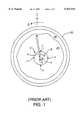
- IVUS systems utilizing mechanical scanningmay use a single rotating transducer 1 in the distal end of a catheter 3 that enters the blood vessel 20, with a drive shaft 5 coupling the transducer 1 to a motor (not shown) coupled to the catheter 3 at its proximal end.
- IVUS systems using mechanical scanninghave wider applications, mainly due to the smaller size of the mechanical scanner in comparison with electronic scanner, that advantageously allow the system to be used for smaller blood vessels as well as larger blood vessels.
- the present inventionrelates to IVUS imaging systems with mechanical scanning.
- an ultrasonic unidirectional exciter/detectore.g., transducer
- a catheter probepositioned within a blood vessel
- vectorsare created by directing focused ultrasonic pressure waves 2 radially from a transducer in a catheter and collecting echoes 4 at the same transducer from the target area, as seen in FIG. 1.
- the transduceris mechanically rotated at a uniform speed with multiple firings of ultrasonic excitation in order to obtain a plurality of equally spaced radial vectors from the collected echoes.
- the plurality of radial vectors from the rotated transducercomprises an image frame.
- a signal processorthen performs image processing (e.g., stabilization of a moving image, temporal filtering for blood speckle, and other image enhancement techniques) on the acquired data in order to provide a display of the corrected and filtered intravascular image on a raster-scan display monitor.
- image processinge.g., stabilization of a moving image, temporal filtering for blood speckle, and other image enhancement techniques
- Some conventional techniques used to detect non-uniform rotation of the transducer in intravascular ultrasound imaginginvolve calibrating the catheter 3 with landmarks or beacons 7, whether active or passive, generally located at various points (circumferentially or helically) along the perimeter of sheath 9 of the catheter 3, as seen in FIG. 1.
- Each beacon's position relative to the catheteris known.
- Passive beaconsact as reflectors of ultrasound transmitted by the catheter and may undesirably cause reflective bright spots on the image which shadow points in the intravascular field behind the spots.
- Active beaconstransmit ultrasonic energy (characterized by phase, amplitude, frequency and/or pulse repetition rate so as to identify the particular beacon) in the direction of the rotating transducer so that the imaging system may identify the particular beacon in order to determine the angular position of the transducer.
- ultrasonic energycharacterized by phase, amplitude, frequency and/or pulse repetition rate so as to identify the particular beacon
- the imaging systemmay identify the particular beacon in order to determine the angular position of the transducer.
- passive or active beaconsare not always effective because the beacons may cause shadowing of tissue behind the beacons or may introduce artifacts adversely affecting the imaging of the anatomical structures.
- the present inventionprovides methods and apparatus which detect non-uniform rotation in an improved manner without using beacons which may create shadowing of tissue behind the beacons or other undesired artifacts in the image.
- the present inventionmay provide a particularly simple and useful solution for addressing the problem of non-uniform rotation distortion in intravascular ultrasound imaging in systems which use mechanical scanning.
- the present inventionprovides a method for detecting non-uniform rotation distortion in an intravascular ultrasound blood vessel image.
- the methodincludes the step of providing a catheter probe within a blood vessel, where the catheter probe includes a sheath and a transducer substantially centrally located within the sheath.
- the transduceris mechanically controlled and the catheter probe also includes a bubbly liquid between the sheath and the transducer.
- the methodalso includes the steps of emitting an ultrasonic beam to produce echoes reflected from the bubbly liquid and the sheath to obtain a given image vector, and sampling the echoes in multiple time windows for the given image vector.
- the methodincludes the step of correlating the sampled echoes in the multiple time windows to determine existence of non-uniform rotational speed of the transducer.
- the present inventionprovides a method for detecting non-uniform rotation distortion in an intravascular ultrasound blood vessel image.
- the methodprovides a catheter probe within a blood vessel, where the catheter probe has a transducer substantially centrally located therein and the transducer is mechanically controlled.
- the methodalso provides steps of emitting multiple ultrasonic beams to produce echoes reflected from a blood region within the blood vessel to obtain multiple successive image vectors, and sampling the echoes at a predetermined range (r P ) for each of the successive image vectors.
- the r P for each of the successive image vectorsis located within the blood region.
- the methodfurther includes obtaining correlation coefficients for the sampled echoes at r P between each of the successive image vectors to determine changes in a rotational speed of the transducer.
- the present inventionprovides related apparatus and other methods for detecting non-uniform rotation distortion in an intravascular ultrasound blood vessel image utilizing correlation.
- FIG. 1is a cross-sectional view of a blood vessel and a catheter probe therein of an exemplary IVUS system utilizing mechanical scanning, in accordance with the prior art;
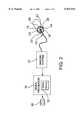
- FIG. 2is a block diagram of an intravascular ultrasonic imaging system in accordance with a specific embodiment of the present invention
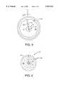
- FIG. 3is a cross-sectional view of a blood vessel and a catheter probe therein of an IVUS system utilizing mechanical scanning, in accordance with the present invention
- FIG. 4is a cross-sectional detailed view of a catheter probe with a bubbly liquid contained therein, according to a specific embodiment of the present invention
- FIGS. 5(a) and 5(b)are exemplary diagrams of the amplitude of multiple echoes received at transducer 22 in relation with time corresponding to distance r ⁇ r S when transducer 22 has uniform rotation and non-uniform rotation, respectively, in accordance with the specific embodiment of FIG. 4;
- FIG. 6(a)is an exemplary diagram illustrating successive vectors for a transducer rotating uniformly, according to another specific embodiment of the present invention.
- FIGS. 6(b)-6(c)are exemplary diagrams illustrating successive vectors for a non-uniformly rotating transducer which is increasing and decreasing, respectively, in rotational speed in comparison to the uniform rotational speed shown in FIG. 6(a).
- FIG. 7(a)is an exemplary diagram illustrating successive vectors for a transducer rotating uniformly, according to yet another specific embodiment of the present invention.
- FIGS. 7(b)-7(c)are exemplary diagrams illustrating successive vectors for a non-uniformly rotating transducer which is increasing and decreasing, respectively, in rotational speed in comparison to the uniform rotational speed shown in FIG. 7(a).
- the present inventionprovides for detection of non-uniform rotation distortion for enhanced image processing in intravascular ultrasound imaging systems.
- the present inventionprovides image processing methods which may be used to detect non-uniform rotation distortion in the displayed image with the intravascular ultrasonic imaging system (shown in FIG. 2) which uses mechanical scanning without active or passive beacons.
- FIG. 2there is shown a block diagram of a type of intravascular ultrasonic imaging system 10 that may be used for intravascular image display in accordance with a specific embodiment of the present invention.
- FIG. 3illustrates a cross-sectional view of a blood vessel and a catheter probe therein of an IVUS system utilizing mechanical scanning in accordance with the present invention.
- a specialized signal processing device 10is used with an ultrasonic imaging system 12 including a catheter probe 13 wherein ultrasonic beams 14 are emitted by an ultrasonic transmitter or exciter 16 of transducer 22, which is at the distal end of catheter 13 and is coupled via drive shaft 5 to a motor (not shown) at the proximal end of catheter 13.
- the ultrasonic signals 14of, for example, 5 Megahertz (MHz) to 50 MHz, are directed to an intravascular target to cause reflections in the form of ultrasonic echo signals 18 from the intravascular structures, including blood.
- Radial spokes or vectors 18 of informationare collected from a target 20 (the interior walls of a blood vessel) based on ultrasonic reflections received at a transducer 22.
- informationis gathered by projecting narrow ultrasonic sampling beams 14 (of a predetermined beamwidth) from exciter 16 as it is rotated (by an angle ⁇ ) within catheter 13 in blood vessel 20.
- the reflectionsscale in amplitude over a range and are recorded by transducer 22 as a function of unit distance (r) along the radius of each vector.
- the imageis representative of a cross-sectional "slice" of the structure of blood vessel 20 and includes wall structures (blood-wall interface) 26 and lumens of blood (blood region) 24, as seen in FIGS. 2 and 3.
- This image datamay be acquired as either analog or digital information, depending on the specific system utilized.
- the data acquiredis converted into pixels representing points in a scanned (swept or rotated) two-dimensional image. These pixels are assigned a value on, for example, a gray scale between black and white. Of course, the assigned value may be on a color scale in other embodiments.
- signal processor 10After the intravascular ultrasonic imaging system acquires the image data, signal processor 10 performs signal processing of the acquired image data and scan-converting the image data into x-y rasterized image data for storing into display memory 32 and then providing the raster image for viewing on a display device 30 coupled to signal processor 10.
- Signal processor 10also includes a program memory 38 which may be used to store the computer-readable program(s) for implementing specific embodiment(s) of the present invention, as discussed further below.
- the computer-readable program(s) for implementing specific embodiments of the present inventionmay be stored on a memory coupled to signal processor 10.
- the memorymay be a read-only memory, fixed disk drive, or removable disk drive.
- transducer 22is mechanically rotated within sheath 9 of catheter 13 at a uniform speed of, for example, about 1800 revolutions per minute with about 300 firings of ultrasonic excitation in order to obtain a plurality of equally spaced radial vectors from the collected echoes for an image frame.
- Intravascular image framesare obtained by sampling reflections received at transducer 22 for r>r S , where r S is the distance between transducer 22 and sheath 9 of catheter 13.
- FIG. 4is a cross-sectional detailed view of a catheter probe with a bubbly liquid contained therein, according to this specific embodiment of the present invention.
- sheath 9is as non-reflective (i.e., as transmissive) of ultrasounds as possible so that ultrasounds may be emitted through sheath 9 and echoes may be received through sheath 9 for imaging purposes.
- at least some portion of sheath 9is reflective of ultrasound to provide the ultrasound reverberation utilized in the present embodiment.
- a first portion along the length of sheath 9 that is ultrasound transmissivemay be used for imaging purposes while a second portion along the length of sheath 9 that is ultrasound reflective may be used for non-uniform rotation purposes.
- liquid 40 which contains micro-bubbles 42By flushing catheter 13 with liquid 40 which contains micro-bubbles 42, a reverberation of ultrasound is created between transducer 22 and sheath 9.
- AlbunexTM available from Molecular Bioscience Inc. or TaligentTM available from Alliance Pharmaceuticalare exemplary bubbly liquids which may be used in the present invention as a contrast agent.
- Micro-bubbles 42 useful with the present embodimenthave a mean diameter on the order of about 4 ⁇ m or less with a distribution ranging between about 1-10 ⁇ m. Transducer 22 thus receives multiple echoes from sheath 9 and micro-bubbles 42 arising from different round trips of the ultrasonic beam echoed within sheath 9.
- FIGS. 5(a) and 5(b)are exemplary diagrams of the amplitude of these multiple echoes received at transducer 22 in relation to time corresponding to distance r ⁇ r S when transducer 22 has uniform rotation and non-uniform rotation, respectively.
- equally spaced segments (amplitude in the time/depth dimension) along an imaging vector within r Swould be correlated with one another. Since the deeper segments of the imaging vector came from multiple round trips of ultrasound between transducer 22 and sheath 9, the correlation or the lack thereof in the different segments of the received signal is a measure of the rotational speed.
- the correlation between two segments of the imaging vector arising from different round trips between transducer and the sheathwould be high.
- equally spaced segments in the image vectorare shown as windows (w 1 , w 2 , w 3 , and w 4 ) in time.
- Each time windowshould be as short as possible but have a sufficient width (i.e.g, time duration) to capture enough information from an echo in order to perform an adequate correlation.
- correlating each of the segments of the image vector with the preceding segmentresults in correlation coefficients of about 0.72, 0.71 and 0.73 for w 2 , w 3 , and W 4 , respectively.
- the highly correlated segmentsindicate that transducer 22 is rotating in a substantially uniform manner. Any rotational non-uniformity of transducer 22 would manifest itself as a notable change in the correlation coefficient in segments of the imaging vector.
- non-uniform rotationmore specifically, an increase in the transducer's rotational speed, has occurred from window W 3 to w 2 ; while non-uniform rotation, more specifically, a decrease in the transducer's rotational speed, has occurred from window W 4 to W 3 .
- the present embodimentis suitable for use with catheters where the distance r S between sheath 9 and transducer 22 is large enough to provide for close ultrasound reverberations with each window being sufficiently wide so as to capture only one reverberation.
- a catheter having a transducer small in size compared to the sheathwhich would have dimensions as required for the particular intravascular application, may be useful for the present embodiment.
- correlation over larger time separationcan also be performed across different segments in different imaging vectors. If transducer 22 is rotating with uniform speed, the correlation coefficient will remain the same for a given separation in time and beamwidth. Multiple correlation coefficients for a given time separation can be made and the average can be used to improve the accuracy of the measurement, in other embodiments.
- the present inventionuses correlation of blood speckle to track the rotation of the transducer.
- This embodimentcould utilize the general correlation expression given in equation 6 or 11 of the Barnea reference, in the 1-dimensional time/depth domain for a given depth (r P ) in successive image vectors.
- a region 50 in the imaging scene where the image texture is full of speckleis selected.
- the correlation coefficientshould be low for respective points r P (in successive image vectors) that are separated from each other by greater than the ultrasound beamwidth (measured in angle); whereas, within blood speckle region 50, the correlation coefficient should be high for respective points r P (in successive image vectors) that are separated from each other by less than the ultrasound beamwidth.
- FIG. 6(a)is an exemplary diagram illustrating successive vectors for a transducer 22 rotating uniformly, according to this specific embodiment.
- the transducer 22is located substantially in the center of blood vessel 20, but it should be recognized that the discussion also applies when transducer 22 is off-center as long as region 50 of blood speckle exists for use with the present embodiment.
- transducer 22is rotating with a uniform rotational speed ⁇ with successive image vectors (specifically, image vector 52 taken for ⁇ i , image vector 54 taken for ⁇ i+1 , and image vector 56 taken for ⁇ i+2 ) being uniformly separated by a uniform angular separation ⁇ .
- the correlation between each successive image vector (between 52 and 54, and between 54 and 56) at the same predetermined range r Pshould be relatively high and substantially similar between successive image vectors which maintain about the same angular separation.
- the lack of fluctuation of the correlation coefficient in successive imaging vectorsindicates a lack of fluctuation (i.e., uniform rotation) in the rotational speed of transducer 21.
- FIGS. 6(b)-6(c)are exemplary diagrams illustrating successive vectors for a non-uniformly rotating transducer which is increasing and decreasing, respectively, in rotational speed in comparison to the uniform rotational speed shown in FIG. 6(a).
- transducer 22rotates with a uniform rotational speed ⁇ from image vector 52 taken for ⁇ i to image vector 54 taken for ⁇ i+1 , which are uniformly separated by a uniform angular separation ⁇ .
- transducer 22starts to rotate with an increasing rotational speed ⁇ + ⁇ 1 , from image vector 54 taken for ⁇ i+1 to image vector 62 taken for ⁇ i+2 .
- the correlation between successive image vectors 52 and 54 at the same predetermined range r Pshould be relatively high and is defmed by C.sub. ⁇ . However, the correlation between successive image vectors 54 and 62 at the same predetermined range r P should be lower than the correlation C.sub. ⁇ between vectors 52 and 54, since successive image vectors 54 and 62 have a wider angular separation compared to the beamwidth.
- the decrease of the correlation coefficient from C.sub. ⁇ in successive imaging vectorsindicates an increase in the rotational speed of transducer 21.
- transducer 22rotates with a uniform rotational speed ⁇ from image vector 52 taken for ⁇ i to image vector 54 taken for ⁇ i+1 , which are uniformly separated by a uniform angular separation ⁇ .
- transducer 22starts to rotate with a decreasing rotational speed ⁇ - ⁇ 2 from image vector 54 taken for ⁇ i+1 to image vector 64 taken for ⁇ i+2 .
- the correlation between successive image vectors 52 and 54 at the same predetermined range r Pshould be relatively high and is defined by C.sub. ⁇ .
- the correlation between successive image vectors 54 and 64 at the same predetermined range r Pshould be higher than the correlation C.sub. ⁇ between vectors 52 and 54, since successive image vectors 54 and 64 have an even smaller angular separation compared to the beamwidth than image vectors 52 and 54.
- the increase of the correlation coefficient from C.sub. ⁇ in successive imaging vectorsindicates a decrease in the rotational speed of transducer 21.
- correlation of blood speckleis used to track the rotation of the transducer.
- These embodimentsalso could utilize the general correlation expression given in equation 6 or 11 of the Barnea reference, in the 1-dimensional time/depth domain for multiple given ranges or depths (r P1 , r P2 , r P3 , etc.) in successive image vectors, in order to provide various measurements of the non-uniform rotation for greater accuracy of detection.
- region 50 in the imaging scene where the image texture is full of speckleis selected for the embodiment of FIGS. 7(a)-7(c).
- FIG. 7(a)is an exemplary diagram illustrating successive vectors for a transducer 22 rotating uniformly, according to the present specific embodiment.
- FIGS. 7(b)-7(c)are exemplary diagrams illustrating successive vectors for a non-uniformly rotating transducer which is increasing and decreasing, respectively, in rotational speed in comparison to the uniform rotational speed shown in FIG. 7(a).
- the transducer 22is located substantially in the center of blood vessel 20, but it should be recognized that the discussion also applies when transducer 22 is off-center as long as region 50 of blood speckle exists for use with the present embodiment. As seen in FIG.
- transducer 22is rotating with a uniform rotational speed ⁇ with successive image vectors (specifically, image vector 72 taken for ⁇ i , image vector 74 taken for ⁇ i+1 , and image vector 56 taken for ⁇ i+2 ) being uniformly separated by a uniform angular separation ⁇ .
- the correlations between each successive image vector (between 52 and 54, and between 54 and 56 ) at the same predetermined ranges r P1 and r P2should be relatively high and substantially similar between successive image vectors which maintain about the same angular separation.
- the lack of fluctuation of the correlation coefficient in successive imaging vectorsindicates a lack of fluctuation (i.e., uniform rotation) in the rotational speed of transducer 22.
- the correlation coefficient at a particular range between successive image vectorsshould be low for values of the range that have a separation greater than the ultrasound beamwidth.
- the correlation coefficient at a particular range between successive image vectorsshould be high for values of the range that have a separation less than the ultrasound beamwidth. Determining the correlation coefficients at more than one range value between successive image vectors enables greater accuracy of the detection of non-uniform rotation.
- the correlation coefficients at both r P1 and r P2 between successive vectorsshould be substantially the same when the successive vectors maintain about the same angular separation (i.e., uniform rotation of transducer 21 ).
- transducer 22rotates with a uniform rotational speed ⁇ from image vector 72 taken for ⁇ i to image vector 74 taken for ⁇ i+1 , which are uniformly separated by a uniform angular separation ⁇ . However, transducer 22 starts to rotate with an increasing rotational speed ⁇ + ⁇ 1 from image vector 74 taken for ⁇ i+1 to image vector 82 taken for ⁇ i+2 .
- the correlations between successive image vectors 74 and 82 at the predetermined ranges r P1 and r P2should both be lower than the correlations C.sub. ⁇ 1 and C.sub. ⁇ 2 between vectors 72 and 74, since successive image vectors 74 and 82 have a wider angular separation compared to the beamwidth.
- the decrease of the correlation coefficients from C.sub. ⁇ 1 and C.sub. ⁇ 2 in successive imaging vectors 74 and 82indicates an increase in the rotational speed of transducer 22. In FIG.
- transducer 22rotates with a uniform rotational speed ⁇ from image vector 72 taken for ⁇ i image vector 74 taken for ⁇ i+1 , which are uniformly separated by a uniform angular separation ⁇ . However, transducer 22 starts to rotate with a decreasing rotational speed ⁇ - ⁇ 2 from image vector 74 taken for ⁇ i+1 , to image vector 84 taken for ⁇ i+2 .
- the correlation between successive image vectors 72 and 74 at the same predetermined ranges r P1 and r P2should be relatively high and are defined as C.sub. ⁇ 1 and C.sub. ⁇ 2, respectively.
- the correlations between successive image vectors 74 and 84 at the same predetermined ranges r P1 and r P2should be higher than the correlations C.sub. ⁇ 1 and C.sub. ⁇ 2 between vectors 72 and 74, since successive image vectors 74 and 84 have an even smaller angular separation compared to the beamwidth than image vectors 72 and 74.
- the increase of the correlation coefficients from C.sub. ⁇ 1 and C.sub. ⁇ 2 in successive imaging vectors 74 and 84indicates a decrease in the rotational speed of transducer 21.
- the value of the correlation at r P1 and the value of the correlation at r P2may be averaged if the values differ (the difference in values being attributed to noise).
- the correlation coefficient between successive vectors at r P1will typically have the same percentage change as the correlation coefficient between successive vectors at r P2 , because the distance between points at r P2 in successive vectors is less than the beamwidth at r P2 by a greater amount than the distance between points at r P1 in successive vectors is less than the beamwidth at r P1 .
- transducer 22rotates with a uniform rotational speed ⁇ from image vector 72 taken for ⁇ i to image vector 74 taken for ⁇ i+1 , which are uniformly separated by a uniform angular separation ⁇ .
- transducer 22starts to rotate with an increasing rotational speed ⁇ + ⁇ 1 from image vector 74 taken for ⁇ i+1 to image vector 82 taken for ⁇ i+2 .
- the correlations between successive image vectors 74 and 82 at the predetermined ranges r P1 and r P2should both be lower by a similar percentage than the correlations C.sub. ⁇ 1 and C.sub.•2 between vectors 72 and 74, since successive image vectors 74 and 82 at r P2 have a narrower angular separation compared to the increased beamwidth at r P2 and successive image vectors 74 and 82 at r P1 have a wider angular separation compared to the decreased beamwidth at r P1 .
- transducer 22rotates with a uniform rotational speed ⁇ from image vector 72 taken for ⁇ i to image vector 74 taken for ⁇ i+1 , which are uniformly separated by a uniform angular separation ⁇ .
- transducer 22starts to rotate with a decreasing rotational speed ⁇ - ⁇ 2 from image vector 74 taken for ⁇ i+1 to image vector 84 taken for ⁇ i+2 .
- the correlation between successive image vectors 72 and 74 at the same predetermined ranges r P1 and r P2should be relatively high and are defined as C.sub. ⁇ 1 and C.sub. ⁇ 2 respectively.
- the correlations between successive image vectors 74 and 84 at the same predetermined ranges r P1 and r P2e.g., the correlation at r P1 between vectors 74 and 82 is about 0.88, and the correlation at r P2 between vectors 74 and 82 is about 0.99
- the increase of the correlation coefficients from C.sub. ⁇ 1 and C.sub. ⁇ 2 in successive imaging vectors 74 and 84indicates a decrease in the rotational speed of transducer 21.
- r Pis preferably selected such that it lies beyond the far-field of the transducer. The far-field of the transducer is determined by the expression
- Ais the radius of the circular transducer and ⁇ is the wavelength of the center frequency f 0 of the transducer.
Landscapes
- Health & Medical Sciences (AREA)
- Life Sciences & Earth Sciences (AREA)
- Engineering & Computer Science (AREA)
- Physics & Mathematics (AREA)
- Remote Sensing (AREA)
- Radar, Positioning & Navigation (AREA)
- Molecular Biology (AREA)
- General Health & Medical Sciences (AREA)
- Pathology (AREA)
- Biomedical Technology (AREA)
- Heart & Thoracic Surgery (AREA)
- Medical Informatics (AREA)
- Nuclear Medicine, Radiotherapy & Molecular Imaging (AREA)
- Surgery (AREA)
- Animal Behavior & Ethology (AREA)
- Radiology & Medical Imaging (AREA)
- Public Health (AREA)
- Veterinary Medicine (AREA)
- Biophysics (AREA)
- Acoustics & Sound (AREA)
- Computer Networks & Wireless Communication (AREA)
- General Physics & Mathematics (AREA)
- Hematology (AREA)
- Ultra Sonic Daignosis Equipment (AREA)
Abstract
Description
r.sub.far-field =(A.sup.2)/λ
Claims (21)
Priority Applications (11)
| Application Number | Priority Date | Filing Date | Title |
|---|---|---|---|
| US08/977,543US5921934A (en) | 1997-11-25 | 1997-11-25 | Methods and apparatus for non-uniform rotation distortion detection in an intravascular ultrasound imaging system |
| DE69831418TDE69831418T2 (en) | 1997-11-25 | 1998-11-24 | METHOD AND DEVICE FOR DISPLAYING ROTATIONAL CONDITIONS IN AN ULTRASONIC IMAGE GENERATION ARRANGEMENT |
| ES98960057TES2246544T3 (en) | 1997-11-25 | 1998-11-24 | METHOD AND APPARATUS FOR THE DETECTION OF DISTORSION BY NON-UNIFORM ROTATION IN AN INTRAVASCULAR VISUALIZATION SYSTEM BY ULTRASOUNDS. |
| JP2000521751AJP4307711B2 (en) | 1997-11-25 | 1998-11-24 | Apparatus for detecting non-uniform rotational distortion in an intravascular ultrasound imaging system |
| EP98960057AEP1033937B1 (en) | 1997-11-25 | 1998-11-24 | Methods and apparatus for non-uniform rotation distorsion detection in an intravascular ultrasound imaging system |
| CA2308505ACA2308505C (en) | 1997-11-25 | 1998-11-24 | Methods and apparatus for non-uniform rotation distortion detection in an intravascular ultrasound imaging system |
| PCT/IB1998/002126WO1999026541A1 (en) | 1997-11-25 | 1998-11-24 | Methods and apparatus for non-uniform rotation distorsion detection in an intravascular ultrasound imaging system |
| AU15736/99AAU1573699A (en) | 1997-11-25 | 1998-11-24 | Methods and apparatus for non-uniform rotation distorsion detection in an intravascular ultrasound imaging system |
| US09/250,462US6120455A (en) | 1997-11-25 | 1999-02-16 | Methods and apparatus for non-uniform rotation distortion detection in an intravascular ultrasound imaging system |
| US09/516,069US6267727B1 (en) | 1997-11-25 | 2000-03-01 | Methods and apparatus for non-uniform rotation distortion detection in an intravascular ultrasound imaging system |
| JP2008297859AJP4393570B2 (en) | 1997-11-25 | 2008-11-21 | Apparatus for detecting non-uniform rotational distortion in an intravascular ultrasound imaging system |
Applications Claiming Priority (1)
| Application Number | Priority Date | Filing Date | Title |
|---|---|---|---|
| US08/977,543US5921934A (en) | 1997-11-25 | 1997-11-25 | Methods and apparatus for non-uniform rotation distortion detection in an intravascular ultrasound imaging system |
Related Child Applications (1)
| Application Number | Title | Priority Date | Filing Date |
|---|---|---|---|
| US09/250,462ContinuationUS6120455A (en) | 1997-11-25 | 1999-02-16 | Methods and apparatus for non-uniform rotation distortion detection in an intravascular ultrasound imaging system |
Publications (1)
| Publication Number | Publication Date |
|---|---|
| US5921934Atrue US5921934A (en) | 1999-07-13 |
Family
ID=25525252
Family Applications (3)
| Application Number | Title | Priority Date | Filing Date |
|---|---|---|---|
| US08/977,543Expired - LifetimeUS5921934A (en) | 1997-11-25 | 1997-11-25 | Methods and apparatus for non-uniform rotation distortion detection in an intravascular ultrasound imaging system |
| US09/250,462Expired - LifetimeUS6120455A (en) | 1997-11-25 | 1999-02-16 | Methods and apparatus for non-uniform rotation distortion detection in an intravascular ultrasound imaging system |
| US09/516,069Expired - LifetimeUS6267727B1 (en) | 1997-11-25 | 2000-03-01 | Methods and apparatus for non-uniform rotation distortion detection in an intravascular ultrasound imaging system |
Family Applications After (2)
| Application Number | Title | Priority Date | Filing Date |
|---|---|---|---|
| US09/250,462Expired - LifetimeUS6120455A (en) | 1997-11-25 | 1999-02-16 | Methods and apparatus for non-uniform rotation distortion detection in an intravascular ultrasound imaging system |
| US09/516,069Expired - LifetimeUS6267727B1 (en) | 1997-11-25 | 2000-03-01 | Methods and apparatus for non-uniform rotation distortion detection in an intravascular ultrasound imaging system |
Country Status (8)
| Country | Link |
|---|---|
| US (3) | US5921934A (en) |
| EP (1) | EP1033937B1 (en) |
| JP (2) | JP4307711B2 (en) |
| AU (1) | AU1573699A (en) |
| CA (1) | CA2308505C (en) |
| DE (1) | DE69831418T2 (en) |
| ES (1) | ES2246544T3 (en) |
| WO (1) | WO1999026541A1 (en) |
Cited By (116)
| Publication number | Priority date | Publication date | Assignee | Title |
|---|---|---|---|---|
| US6152878A (en)* | 1997-06-19 | 2000-11-28 | Medinol Ltd. | Intravascular ultrasound enhanced image and signal processing |
| US6233476B1 (en)* | 1999-05-18 | 2001-05-15 | Mediguide Ltd. | Medical positioning system |
| US6267727B1 (en) | 1997-11-25 | 2001-07-31 | Scimed Life Systems, Inc. | Methods and apparatus for non-uniform rotation distortion detection in an intravascular ultrasound imaging system |
| US6416492B1 (en) | 2000-09-28 | 2002-07-09 | Scimed Life Systems, Inc. | Radiation delivery system utilizing intravascular ultrasound |
| US6450964B1 (en)* | 2000-09-05 | 2002-09-17 | Advanced Cardiovascular Systems, Inc. | Imaging apparatus and method |
| US6522781B1 (en)* | 1998-12-10 | 2003-02-18 | Sysmex Corporation | Particle image analyzer |
| US6585763B1 (en) | 1997-10-14 | 2003-07-01 | Vascusense, Inc. | Implantable therapeutic device and method |
| US20040030700A1 (en)* | 2002-05-27 | 2004-02-12 | Rie Hakamata | Document management system, document management apparatus, authentication method, program for implementing the method, and storage medium storing the program |
| US20040236205A1 (en)* | 2003-05-21 | 2004-11-25 | Warren Lee | Systems and methods for improving the imaging resolution of an imaging transducer |
| US20070106155A1 (en)* | 2005-10-31 | 2007-05-10 | Novelis, Inc. | System and method for reducing angular geometric distortion in an imaging device |
| US20070123979A1 (en)* | 2005-06-27 | 2007-05-31 | Patrick Perier | Apparatus, system, and method for treatment of posterior leaflet prolapse |
| US20070250000A1 (en)* | 2006-03-30 | 2007-10-25 | Novelis, Inc. | Method and system for imaging, diagnosing, and/or treating an area of interest in a patient's body |
| US20070268287A1 (en)* | 2006-05-22 | 2007-11-22 | Magnin Paul A | Apparatus and method for rendering for display forward-looking image data |
| US20080208059A1 (en)* | 2005-03-11 | 2008-08-28 | Koninklijke Philips Electronics, N.V. | Microbubble Generating Technique For Phase Aberration Correction |
| US20080287801A1 (en)* | 2006-08-14 | 2008-11-20 | Novelis, Inc. | Imaging device, imaging system, and methods of imaging |
| US20090157174A1 (en)* | 2005-12-15 | 2009-06-18 | Georgia Tech Reasearch Corporation | Systems and methods for enabling heart valve replacement |
| US20090177276A1 (en)* | 2007-02-09 | 2009-07-09 | Edwards Lifesciences Corporation | Degenerative Valvular Disease Specific Annuloplasty Rings |
| US20090306518A1 (en)* | 2008-06-06 | 2009-12-10 | Boston Scientific Scimed, Inc. | Transducers, devices and systems containing the transducers, and methods of manufacture |
| US20100023117A1 (en)* | 2005-12-15 | 2010-01-28 | Georgia Tech Research Corporation | Papillary muscle position control devices, systems, & methods |
| US20100024561A1 (en)* | 2006-10-20 | 2010-02-04 | Kevin Corcoran | Method and apparatus for measuring pressure inside a fluid system |
| US20100063586A1 (en)* | 2006-05-15 | 2010-03-11 | John Michael Hasenkam | System and a method for altering the geometry of the heart |
| US7819915B2 (en) | 2000-07-27 | 2010-10-26 | Edwards Lifesciences Corporation | Heart valve holders and handling clips therefor |
| US20100312109A1 (en)* | 2009-06-03 | 2010-12-09 | Fujifilm Corporation | Ultrasonic diagnostic apparatus and signal processing program |
| US20110118590A1 (en)* | 2009-11-18 | 2011-05-19 | Siemens Medical Solutions Usa, Inc. | System For Continuous Cardiac Imaging And Mapping |
| US7951197B2 (en) | 2005-04-08 | 2011-05-31 | Medtronic, Inc. | Two-piece prosthetic valves with snap-in connection and methods for use |
| US7959674B2 (en) | 2002-07-16 | 2011-06-14 | Medtronic, Inc. | Suture locking assembly and method of use |
| US7967857B2 (en) | 2006-01-27 | 2011-06-28 | Medtronic, Inc. | Gasket with spring collar for prosthetic heart valves and methods for making and using them |
| US7972377B2 (en) | 2001-12-27 | 2011-07-05 | Medtronic, Inc. | Bioprosthetic heart valve |
| US7981153B2 (en) | 2002-12-20 | 2011-07-19 | Medtronic, Inc. | Biologically implantable prosthesis methods of using |
| US8021421B2 (en) | 2003-08-22 | 2011-09-20 | Medtronic, Inc. | Prosthesis heart valve fixturing device |
| US8021161B2 (en) | 2006-05-01 | 2011-09-20 | Edwards Lifesciences Corporation | Simulated heart valve root for training and testing |
| US20110245673A1 (en)* | 2010-03-31 | 2011-10-06 | Kabushiki Kaisha Toshiba | Ultrasound diagnosis apparatus, image processing apparatus, and image processing method |
| US8211169B2 (en) | 2005-05-27 | 2012-07-03 | Medtronic, Inc. | Gasket with collar for prosthetic heart valves and methods for using them |
| US20120245469A1 (en)* | 2011-03-22 | 2012-09-27 | Mcgee David | Far-field and near-field ultrasound imaging device |
| US8308798B2 (en) | 2008-12-19 | 2012-11-13 | Edwards Lifesciences Corporation | Quick-connect prosthetic heart valve and methods |
| US8348998B2 (en) | 2009-06-26 | 2013-01-08 | Edwards Lifesciences Corporation | Unitary quick connect prosthetic heart valve and deployment system and methods |
| US8506625B2 (en) | 2005-07-13 | 2013-08-13 | Edwards Lifesciences Corporation | Contoured sewing ring for a prosthetic mitral heart valve |
| US8529621B2 (en) | 2001-05-17 | 2013-09-10 | Edwards Lifesciences Corporation | Methods of repairing an abnormal mitral valve |
| US8574257B2 (en) | 2005-02-10 | 2013-11-05 | Edwards Lifesciences Corporation | System, device, and method for providing access in a cardiovascular environment |
| US8603161B2 (en) | 2003-10-08 | 2013-12-10 | Medtronic, Inc. | Attachment device and methods of using the same |
| US8641757B2 (en) | 2010-09-10 | 2014-02-04 | Edwards Lifesciences Corporation | Systems for rapidly deploying surgical heart valves |
| US8670603B2 (en) | 2007-03-08 | 2014-03-11 | Sync-Rx, Ltd. | Apparatus and methods for masking a portion of a moving image stream |
| US8700130B2 (en) | 2007-03-08 | 2014-04-15 | Sync-Rx, Ltd. | Stepwise advancement of a medical tool |
| US8821569B2 (en) | 2006-04-29 | 2014-09-02 | Medtronic, Inc. | Multiple component prosthetic heart valve assemblies and methods for delivering them |
| US8845720B2 (en) | 2010-09-27 | 2014-09-30 | Edwards Lifesciences Corporation | Prosthetic heart valve frame with flexible commissures |
| US8855744B2 (en) | 2008-11-18 | 2014-10-07 | Sync-Rx, Ltd. | Displaying a device within an endoluminal image stack |
| US8986374B2 (en) | 2010-05-10 | 2015-03-24 | Edwards Lifesciences Corporation | Prosthetic heart valve |
| US9078747B2 (en) | 2011-12-21 | 2015-07-14 | Edwards Lifesciences Corporation | Anchoring device for replacing or repairing a heart valve |
| US9095313B2 (en) | 2008-11-18 | 2015-08-04 | Sync-Rx, Ltd. | Accounting for non-uniform longitudinal motion during movement of an endoluminal imaging probe |
| US9101286B2 (en) | 2008-11-18 | 2015-08-11 | Sync-Rx, Ltd. | Apparatus and methods for determining a dimension of a portion of a stack of endoluminal data points |
| US9101472B2 (en) | 2007-09-07 | 2015-08-11 | Edwards Lifesciences Corporation | Active holder for annuloplasty ring delivery |
| US9125741B2 (en) | 2010-09-10 | 2015-09-08 | Edwards Lifesciences Corporation | Systems and methods for ensuring safe and rapid deployment of prosthetic heart valves |
| US9144394B2 (en) | 2008-11-18 | 2015-09-29 | Sync-Rx, Ltd. | Apparatus and methods for determining a plurality of local calibration factors for an image |
| US9149359B2 (en) | 2001-08-28 | 2015-10-06 | Edwards Lifesciences Corporation | Three-dimensional annuloplasty ring |
| US9155617B2 (en) | 2004-01-23 | 2015-10-13 | Edwards Lifesciences Corporation | Prosthetic mitral valve |
| US9248016B2 (en) | 2009-03-31 | 2016-02-02 | Edwards Lifesciences Corporation | Prosthetic heart valve system |
| US9277996B2 (en) | 2011-12-09 | 2016-03-08 | Edwards Lifesciences Corporation | Force-based heart valve sizer |
| US9305334B2 (en) | 2007-03-08 | 2016-04-05 | Sync-Rx, Ltd. | Luminal background cleaning |
| US9314334B2 (en) | 2008-11-25 | 2016-04-19 | Edwards Lifesciences Corporation | Conformal expansion of prosthetic devices to anatomical shapes |
| US9326858B2 (en) | 2010-08-24 | 2016-05-03 | Edwards Lifesciences Corporation | Flexible annuloplasty ring |
| US9345574B2 (en) | 2011-12-09 | 2016-05-24 | Edwards Lifesciences Corporation | Force-based heart valve sizer |
| US9370418B2 (en) | 2010-09-10 | 2016-06-21 | Edwards Lifesciences Corporation | Rapidly deployable surgical heart valves |
| US9375164B2 (en) | 2007-03-08 | 2016-06-28 | Sync-Rx, Ltd. | Co-use of endoluminal data and extraluminal imaging |
| US9439762B2 (en) | 2000-06-01 | 2016-09-13 | Edwards Lifesciences Corporation | Methods of implant of a heart valve with a convertible sewing ring |
| US9468527B2 (en) | 2013-06-12 | 2016-10-18 | Edwards Lifesciences Corporation | Cardiac implant with integrated suture fasteners |
| US9474607B2 (en) | 2010-11-30 | 2016-10-25 | Edwards Lifesciences Corporation | Methods of implanting an annuloplasty ring for reduced dehiscence |
| US9504566B2 (en) | 2014-06-20 | 2016-11-29 | Edwards Lifesciences Corporation | Surgical heart valves identifiable post-implant |
| US9549816B2 (en) | 2014-04-03 | 2017-01-24 | Edwards Lifesciences Corporation | Method for manufacturing high durability heart valve |
| US9554903B2 (en) | 2005-05-24 | 2017-01-31 | Edwards Lifesciences Corporation | Rapid deployment prosthetic heart valve |
| US9554901B2 (en) | 2010-05-12 | 2017-01-31 | Edwards Lifesciences Corporation | Low gradient prosthetic heart valve |
| US9572519B2 (en) | 1999-05-18 | 2017-02-21 | Mediguide Ltd. | Method and apparatus for invasive device tracking using organ timing signal generated from MPS sensors |
| US9585752B2 (en) | 2014-04-30 | 2017-03-07 | Edwards Lifesciences Corporation | Holder and deployment system for surgical heart valves |
| US9629571B2 (en) | 2007-03-08 | 2017-04-25 | Sync-Rx, Ltd. | Co-use of endoluminal data and extraluminal imaging |
| US9687346B2 (en) | 2013-03-14 | 2017-06-27 | Edwards Lifesciences Corporation | Multi-stranded heat set annuloplasty rings |
| US9855384B2 (en) | 2007-03-08 | 2018-01-02 | Sync-Rx, Ltd. | Automatic enhancement of an image stream of a moving organ and displaying as a movie |
| US9888969B2 (en) | 2007-03-08 | 2018-02-13 | Sync-Rx Ltd. | Automatic quantitative vessel analysis |
| US9919137B2 (en) | 2013-08-28 | 2018-03-20 | Edwards Lifesciences Corporation | Integrated balloon catheter inflation system |
| US9974509B2 (en) | 2008-11-18 | 2018-05-22 | Sync-Rx Ltd. | Image super enhancement |
| US10039531B2 (en) | 2005-12-15 | 2018-08-07 | Georgia Tech Research Corporation | Systems and methods to control the dimension of a heart valve |
| US10058425B2 (en) | 2013-03-15 | 2018-08-28 | Edwards Lifesciences Corporation | Methods of assembling a valved aortic conduit |
| US10080653B2 (en) | 2015-09-10 | 2018-09-25 | Edwards Lifesciences Corporation | Limited expansion heart valve |
| US10166101B2 (en) | 2001-05-17 | 2019-01-01 | Edwards Lifesciences Corporation | Methods for repairing mitral valves |
| USD846122S1 (en) | 2016-12-16 | 2019-04-16 | Edwards Lifesciences Corporation | Heart valve sizer |
| US10314707B2 (en) | 2015-06-09 | 2019-06-11 | Edwards Lifesciences, Llc | Asymmetric mitral annuloplasty band |
| US10362962B2 (en) | 2008-11-18 | 2019-07-30 | Synx-Rx, Ltd. | Accounting for skipped imaging locations during movement of an endoluminal imaging probe |
| US10441415B2 (en) | 2013-09-20 | 2019-10-15 | Edwards Lifesciences Corporation | Heart valves with increased effective orifice area |
| US10456245B2 (en) | 2016-05-16 | 2019-10-29 | Edwards Lifesciences Corporation | System and method for applying material to a stent |
| US10456246B2 (en) | 2015-07-02 | 2019-10-29 | Edwards Lifesciences Corporation | Integrated hybrid heart valves |
| US10463485B2 (en) | 2017-04-06 | 2019-11-05 | Edwards Lifesciences Corporation | Prosthetic valve holders with automatic deploying mechanisms |
| USD867594S1 (en) | 2015-06-19 | 2019-11-19 | Edwards Lifesciences Corporation | Prosthetic heart valve |
| US10543080B2 (en) | 2011-05-20 | 2020-01-28 | Edwards Lifesciences Corporation | Methods of making encapsulated heart valves |
| US10667904B2 (en) | 2016-03-08 | 2020-06-02 | Edwards Lifesciences Corporation | Valve implant with integrated sensor and transmitter |
| US10695170B2 (en) | 2015-07-02 | 2020-06-30 | Edwards Lifesciences Corporation | Hybrid heart valves adapted for post-implant expansion |
| US10716528B2 (en) | 2007-03-08 | 2020-07-21 | Sync-Rx, Ltd. | Automatic display of previously-acquired endoluminal images |
| US10722316B2 (en) | 2013-11-06 | 2020-07-28 | Edwards Lifesciences Corporation | Bioprosthetic heart valves having adaptive seals to minimize paravalvular leakage |
| US10748289B2 (en) | 2012-06-26 | 2020-08-18 | Sync-Rx, Ltd | Coregistration of endoluminal data points with values of a luminal-flow-related index |
| CN111671468A (en)* | 2020-05-28 | 2020-09-18 | 昆山戎影医疗科技有限公司 | Asynchronous focusing dynamic compensation method for intravascular ultrasonic single-array-element transducer |
| US10799353B2 (en) | 2017-04-28 | 2020-10-13 | Edwards Lifesciences Corporation | Prosthetic heart valve with collapsible holder |
| USD908874S1 (en) | 2018-07-11 | 2021-01-26 | Edwards Lifesciences Corporation | Collapsible heart valve sizer |
| US11007058B2 (en) | 2013-03-15 | 2021-05-18 | Edwards Lifesciences Corporation | Valved aortic conduits |
| US11064903B2 (en) | 2008-11-18 | 2021-07-20 | Sync-Rx, Ltd | Apparatus and methods for mapping a sequence of images to a roadmap image |
| US11064964B2 (en) | 2007-03-08 | 2021-07-20 | Sync-Rx, Ltd | Determining a characteristic of a lumen by measuring velocity of a contrast agent |
| US11135057B2 (en) | 2017-06-21 | 2021-10-05 | Edwards Lifesciences Corporation | Dual-wireform limited expansion heart valves |
| US11197651B2 (en) | 2007-03-08 | 2021-12-14 | Sync-Rx, Ltd. | Identification and presentation of device-to-vessel relative motion |
| US11213393B2 (en) | 2011-04-01 | 2022-01-04 | Edwards Lifesciences Corporation | Compressible heart valve annulus sizing templates |
| US11337805B2 (en) | 2018-01-23 | 2022-05-24 | Edwards Lifesciences Corporation | Prosthetic valve holders, systems, and methods |
| US11554015B2 (en) | 2018-07-30 | 2023-01-17 | Edwards Lifesciences Corporation | Minimally-invasive low strain annuloplasty ring |
| US11554012B2 (en) | 2019-12-16 | 2023-01-17 | Edwards Lifesciences Corporation | Valve holder assembly with suture looping protection |
| US11690709B2 (en) | 2015-09-02 | 2023-07-04 | Edwards Lifesciences Corporation | Methods for securing a transcatheter valve to a bioprosthetic cardiac structure |
| US12201734B2 (en) | 2017-10-13 | 2025-01-21 | Edwards Lifesciences Corporation | Method for sterilizing heart valves |
| CN119745430A (en)* | 2024-12-27 | 2025-04-04 | 深圳皓影医疗科技有限公司 | Image acquisition system |
| US12311095B2 (en) | 2014-08-06 | 2025-05-27 | Edwards Lifesciences Corporation | Multi-lumen cannulae |
| US12336908B2 (en) | 2012-07-31 | 2025-06-24 | Edwards Lifesciences Corporation | Pre-constricted prosthetic heart valves |
| US12385163B2 (en) | 2019-08-02 | 2025-08-12 | Edwards Lifesciences Corporation | Rotary fibrous material application to medical devices |
| US12383397B2 (en) | 2019-02-05 | 2025-08-12 | Edwards Lifesciences Corporation | Prosthetic heart valve with suture loop preventing member |
| US12440328B2 (en) | 2022-03-25 | 2025-10-14 | Edwards Lifesciences Corporation | Modified prosthetic heart valve stent |
Families Citing this family (12)
| Publication number | Priority date | Publication date | Assignee | Title |
|---|---|---|---|---|
| US7024025B2 (en)* | 2002-02-05 | 2006-04-04 | Scimed Life Systems, Inc. | Nonuniform Rotational Distortion (NURD) reduction |
| ATE499880T1 (en)* | 2002-09-27 | 2011-03-15 | Olympus Corp | ULTRASONIC DIAGNOSTIC DEVICE |
| US20080123911A1 (en)* | 2006-09-26 | 2008-05-29 | Duc Lam | Systems and Methods for Restoring a Medical Image Affected by Nonuniform Rotational Distortion |
| US8206308B2 (en) | 2008-05-05 | 2012-06-26 | Boston Scientific Scimed, Inc. | Shielding for intravascular ultrasound imaging systems and methods of making and using |
| JP5757687B2 (en)* | 2010-02-09 | 2015-07-29 | シャープ株式会社 | Light emitting device, surface light source device, liquid crystal display device, and method for manufacturing light emitting device |
| JP2012030053A (en) | 2010-06-30 | 2012-02-16 | Toshiba Corp | Ultrasound diagnosis apparatus, image processing apparatus and image processing method |
| JP5944913B2 (en)* | 2010-10-28 | 2016-07-05 | ボストン サイエンティフィック サイムド,インコーポレイテッドBoston Scientific Scimed,Inc. | Computer readable medium for reducing non-uniform rotational distortion in ultrasound images and system including the same |
| JP5944917B2 (en)* | 2010-11-24 | 2016-07-05 | ボストン サイエンティフィック サイムド,インコーポレイテッドBoston Scientific Scimed,Inc. | Computer readable medium for detecting and displaying body lumen bifurcation and system including the same |
| JP6440359B2 (en) | 2011-01-31 | 2018-12-19 | サニーブルック ヘルス サイエンシーズ センター | Ultrasonic probe with an ultrasonic transducer that can be processed on a common electrical channel |
| CA2948279A1 (en) | 2014-02-05 | 2015-08-13 | Verathon Inc. | Ultrasonic data collection |
| CA2994309A1 (en)* | 2015-10-30 | 2017-05-04 | Georgia Tech Research Corporation | Foldable 2-d cmut-on-cmos arrays |
| WO2017149352A1 (en)* | 2016-03-01 | 2017-09-08 | B-K Medical Aps | 3-d ultrasound imaging with multiple single-element transducers and ultrasound signal propagation correction |
Citations (2)
| Publication number | Priority date | Publication date | Assignee | Title |
|---|---|---|---|---|
| US5476096A (en)* | 1994-02-09 | 1995-12-19 | Vingmed Sound A/S | Analysis and measurement of temporal tissue variations |
| US5485845A (en)* | 1995-05-04 | 1996-01-23 | Hewlett Packard Company | Rotary encoder for intravascular ultrasound catheter |
Family Cites Families (9)
| Publication number | Priority date | Publication date | Assignee | Title |
|---|---|---|---|---|
| US5115814A (en)* | 1989-08-18 | 1992-05-26 | Intertherapy, Inc. | Intravascular ultrasonic imaging probe and methods of using same |
| US5438997A (en)* | 1991-03-13 | 1995-08-08 | Sieben; Wayne | Intravascular imaging apparatus and methods for use and manufacture |
| US5377682A (en)* | 1991-09-05 | 1995-01-03 | Matsushita Electric Industrial Co., Ltd. | Ultrasonic probe for transmission and reception of ultrasonic wave and ultrasonic diagnostic apparatus including ultrasonic probe |
| US5713363A (en)* | 1991-11-08 | 1998-02-03 | Mayo Foundation For Medical Education And Research | Ultrasound catheter and method for imaging and hemodynamic monitoring |
| US5302372A (en)* | 1992-07-27 | 1994-04-12 | National Science Council | Method to opacify left ventricle in echocardiography |
| JPH0780645A (en)* | 1993-09-08 | 1995-03-28 | Fanuc Ltd | Cooling method of welding sensor |
| US5363850A (en)* | 1994-01-26 | 1994-11-15 | Cardiovascular Imaging Systems, Inc. | Method for recognition and reduction of blood speckle in blood vessel imaging system |
| US5443457A (en)* | 1994-02-24 | 1995-08-22 | Cardiovascular Imaging Systems, Incorporated | Tracking tip for a short lumen rapid exchange catheter |
| US5921934A (en) | 1997-11-25 | 1999-07-13 | Scimed Life Systems, Inc. | Methods and apparatus for non-uniform rotation distortion detection in an intravascular ultrasound imaging system |
- 1997
- 1997-11-25USUS08/977,543patent/US5921934A/ennot_activeExpired - Lifetime
- 1998
- 1998-11-24EPEP98960057Apatent/EP1033937B1/ennot_activeExpired - Lifetime
- 1998-11-24WOPCT/IB1998/002126patent/WO1999026541A1/enactiveIP Right Grant
- 1998-11-24JPJP2000521751Apatent/JP4307711B2/ennot_activeExpired - Lifetime
- 1998-11-24ESES98960057Tpatent/ES2246544T3/ennot_activeExpired - Lifetime
- 1998-11-24AUAU15736/99Apatent/AU1573699A/ennot_activeAbandoned
- 1998-11-24CACA2308505Apatent/CA2308505C/ennot_activeExpired - Fee Related
- 1998-11-24DEDE69831418Tpatent/DE69831418T2/ennot_activeExpired - Fee Related
- 1999
- 1999-02-16USUS09/250,462patent/US6120455A/ennot_activeExpired - Lifetime
- 2000
- 2000-03-01USUS09/516,069patent/US6267727B1/ennot_activeExpired - Lifetime
- 2008
- 2008-11-21JPJP2008297859Apatent/JP4393570B2/ennot_activeExpired - Lifetime
Patent Citations (2)
| Publication number | Priority date | Publication date | Assignee | Title |
|---|---|---|---|---|
| US5476096A (en)* | 1994-02-09 | 1995-12-19 | Vingmed Sound A/S | Analysis and measurement of temporal tissue variations |
| US5485845A (en)* | 1995-05-04 | 1996-01-23 | Hewlett Packard Company | Rotary encoder for intravascular ultrasound catheter |
Non-Patent Citations (4)
| Title |
|---|
| Barnea, Daniel I. and Silverman, Harvey F., "A Class of Algorithms for Fast Digital Image Registration," IEEE Transactions on Computers, vol. C-21, No. 2, Feb. 1972, pp. 179-186. |
| Barnea, Daniel I. and Silverman, Harvey F., A Class of Algorithms for Fast Digital Image Registration, IEEE Transactions on Computers , vol. C 21, No. 2, Feb. 1972, pp. 179 186.* |
| Maragos, Petros, "Morphological Correlation and Mean Absolute Error Criteria," IEEE, 1989, pp. 1568-1571. |
| Maragos, Petros, Morphological Correlation and Mean Absolute Error Criteria, IEEE , 1989, pp. 1568 1571.* |
Cited By (255)
| Publication number | Priority date | Publication date | Assignee | Title |
|---|---|---|---|---|
| US6152878A (en)* | 1997-06-19 | 2000-11-28 | Medinol Ltd. | Intravascular ultrasound enhanced image and signal processing |
| US6585763B1 (en) | 1997-10-14 | 2003-07-01 | Vascusense, Inc. | Implantable therapeutic device and method |
| US6267727B1 (en) | 1997-11-25 | 2001-07-31 | Scimed Life Systems, Inc. | Methods and apparatus for non-uniform rotation distortion detection in an intravascular ultrasound imaging system |
| US6522781B1 (en)* | 1998-12-10 | 2003-02-18 | Sysmex Corporation | Particle image analyzer |
| US10251712B2 (en) | 1999-05-18 | 2019-04-09 | Mediguide Ltd. | Method and apparatus for invasive device tracking using organ timing signal generated from MPS sensors |
| US6233476B1 (en)* | 1999-05-18 | 2001-05-15 | Mediguide Ltd. | Medical positioning system |
| US9572519B2 (en) | 1999-05-18 | 2017-02-21 | Mediguide Ltd. | Method and apparatus for invasive device tracking using organ timing signal generated from MPS sensors |
| US9956049B2 (en) | 1999-05-18 | 2018-05-01 | Mediguide Ltd. | Method and apparatus for invasive device tracking using organ timing signal generated from MPS sensors |
| US9439762B2 (en) | 2000-06-01 | 2016-09-13 | Edwards Lifesciences Corporation | Methods of implant of a heart valve with a convertible sewing ring |
| US10238486B2 (en) | 2000-06-01 | 2019-03-26 | Edwards Lifesciences Corporation | Heart valve with integrated stent and sewing ring |
| US7819915B2 (en) | 2000-07-27 | 2010-10-26 | Edwards Lifesciences Corporation | Heart valve holders and handling clips therefor |
| US6450964B1 (en)* | 2000-09-05 | 2002-09-17 | Advanced Cardiovascular Systems, Inc. | Imaging apparatus and method |
| US6416492B1 (en) | 2000-09-28 | 2002-07-09 | Scimed Life Systems, Inc. | Radiation delivery system utilizing intravascular ultrasound |
| US8529621B2 (en) | 2001-05-17 | 2013-09-10 | Edwards Lifesciences Corporation | Methods of repairing an abnormal mitral valve |
| US10166101B2 (en) | 2001-05-17 | 2019-01-01 | Edwards Lifesciences Corporation | Methods for repairing mitral valves |
| US10188518B2 (en) | 2001-08-28 | 2019-01-29 | Edwards Lifesciences Corporation | Annuloplasty ring with variable cross-section |
| US9414922B2 (en) | 2001-08-28 | 2016-08-16 | Edwards Lifesciences Corporation | Three-dimensional annuloplasty ring |
| US9149359B2 (en) | 2001-08-28 | 2015-10-06 | Edwards Lifesciences Corporation | Three-dimensional annuloplasty ring |
| US7972377B2 (en) | 2001-12-27 | 2011-07-05 | Medtronic, Inc. | Bioprosthetic heart valve |
| US20040030700A1 (en)* | 2002-05-27 | 2004-02-12 | Rie Hakamata | Document management system, document management apparatus, authentication method, program for implementing the method, and storage medium storing the program |
| US7959674B2 (en) | 2002-07-16 | 2011-06-14 | Medtronic, Inc. | Suture locking assembly and method of use |
| US8349003B2 (en) | 2002-07-16 | 2013-01-08 | Medtronic, Inc. | Suture locking assembly and method of use |
| US8551162B2 (en) | 2002-12-20 | 2013-10-08 | Medtronic, Inc. | Biologically implantable prosthesis |
| US8460373B2 (en) | 2002-12-20 | 2013-06-11 | Medtronic, Inc. | Method for implanting a heart valve within an annulus of a patient |
| US8623080B2 (en) | 2002-12-20 | 2014-01-07 | Medtronic, Inc. | Biologically implantable prosthesis and methods of using the same |
| US10595991B2 (en) | 2002-12-20 | 2020-03-24 | Medtronic, Inc. | Heart valve assemblies |
| US8025695B2 (en) | 2002-12-20 | 2011-09-27 | Medtronic, Inc. | Biologically implantable heart valve system |
| US9333078B2 (en) | 2002-12-20 | 2016-05-10 | Medtronic, Inc. | Heart valve assemblies |
| US7981153B2 (en) | 2002-12-20 | 2011-07-19 | Medtronic, Inc. | Biologically implantable prosthesis methods of using |
| US20040236205A1 (en)* | 2003-05-21 | 2004-11-25 | Warren Lee | Systems and methods for improving the imaging resolution of an imaging transducer |
| US7909766B2 (en) | 2003-05-21 | 2011-03-22 | Scimed Life Systems, Inc. | Systems and methods for improving the imaging resolution of an imaging transducer |
| US8021421B2 (en) | 2003-08-22 | 2011-09-20 | Medtronic, Inc. | Prosthesis heart valve fixturing device |
| US8747463B2 (en) | 2003-08-22 | 2014-06-10 | Medtronic, Inc. | Methods of using a prosthesis fixturing device |
| US8603161B2 (en) | 2003-10-08 | 2013-12-10 | Medtronic, Inc. | Attachment device and methods of using the same |
| US9155617B2 (en) | 2004-01-23 | 2015-10-13 | Edwards Lifesciences Corporation | Prosthetic mitral valve |
| US10342661B2 (en) | 2004-01-23 | 2019-07-09 | Edwards Lifesciences Corporation | Prosthetic mitral valve |
| US9730794B2 (en) | 2004-01-23 | 2017-08-15 | Edwards Lifesciences Corporation | Prosthetic mitral valve |
| US10085836B2 (en) | 2004-01-23 | 2018-10-02 | Edwards Lifesciences Corporation | Prosthetic mitral valve |
| US8574257B2 (en) | 2005-02-10 | 2013-11-05 | Edwards Lifesciences Corporation | System, device, and method for providing access in a cardiovascular environment |
| US20080208059A1 (en)* | 2005-03-11 | 2008-08-28 | Koninklijke Philips Electronics, N.V. | Microbubble Generating Technique For Phase Aberration Correction |
| US9022939B2 (en)* | 2005-03-11 | 2015-05-05 | Koninklijke Philips N.V. | Microbubble generating technique for phase aberration correction |
| US8500802B2 (en) | 2005-04-08 | 2013-08-06 | Medtronic, Inc. | Two-piece prosthetic valves with snap-in connection and methods for use |
| US7951197B2 (en) | 2005-04-08 | 2011-05-31 | Medtronic, Inc. | Two-piece prosthetic valves with snap-in connection and methods for use |
| US10456251B2 (en) | 2005-05-24 | 2019-10-29 | Edwards Lifesciences Corporation | Surgical methods of replacing prosthetic heart valves |
| US9554903B2 (en) | 2005-05-24 | 2017-01-31 | Edwards Lifesciences Corporation | Rapid deployment prosthetic heart valve |
| US11284998B2 (en) | 2005-05-24 | 2022-03-29 | Edwards Lifesciences Corporation | Surgical methods of replacing prosthetic heart valves |
| US10130468B2 (en) | 2005-05-24 | 2018-11-20 | Edwards Lifesciences Corporation | Replacement prosthetic heart valves |
| US8211169B2 (en) | 2005-05-27 | 2012-07-03 | Medtronic, Inc. | Gasket with collar for prosthetic heart valves and methods for using them |
| US8685083B2 (en) | 2005-06-27 | 2014-04-01 | Edwards Lifesciences Corporation | Apparatus, system, and method for treatment of posterior leaflet prolapse |
| US20070123979A1 (en)* | 2005-06-27 | 2007-05-31 | Patrick Perier | Apparatus, system, and method for treatment of posterior leaflet prolapse |
| US8506625B2 (en) | 2005-07-13 | 2013-08-13 | Edwards Lifesciences Corporation | Contoured sewing ring for a prosthetic mitral heart valve |
| US8414496B2 (en) | 2005-10-31 | 2013-04-09 | Volcano Corporation | System and method for reducing angular geometric distortion in an imaging device |
| US8047996B2 (en) | 2005-10-31 | 2011-11-01 | Volcano Corporation | System and method for reducing angular geometric distortion in an imaging device |
| US20070106155A1 (en)* | 2005-10-31 | 2007-05-10 | Novelis, Inc. | System and method for reducing angular geometric distortion in an imaging device |
| US9125742B2 (en) | 2005-12-15 | 2015-09-08 | Georgia Tech Research Foundation | Papillary muscle position control devices, systems, and methods |
| US8568473B2 (en) | 2005-12-15 | 2013-10-29 | Georgia Tech Research Corporation | Systems and methods for enabling heart valve replacement |
| US10010419B2 (en) | 2005-12-15 | 2018-07-03 | Georgia Tech Research Corporation | Papillary muscle position control devices, systems, and methods |
| US10039531B2 (en) | 2005-12-15 | 2018-08-07 | Georgia Tech Research Corporation | Systems and methods to control the dimension of a heart valve |
| US20090157174A1 (en)* | 2005-12-15 | 2009-06-18 | Georgia Tech Reasearch Corporation | Systems and methods for enabling heart valve replacement |
| US20100023117A1 (en)* | 2005-12-15 | 2010-01-28 | Georgia Tech Research Corporation | Papillary muscle position control devices, systems, & methods |
| US7967857B2 (en) | 2006-01-27 | 2011-06-28 | Medtronic, Inc. | Gasket with spring collar for prosthetic heart valves and methods for making and using them |
| US8491567B2 (en) | 2006-03-30 | 2013-07-23 | Volcano Corporation | Method and system for imaging, diagnosing, and/or treating an area of interest in a patient's body |
| US10512446B2 (en) | 2006-03-30 | 2019-12-24 | Volcano Corporation | Method and system for imaging, diagnosing, and/or treating an area of interest in a patient's body |
| US20070250000A1 (en)* | 2006-03-30 | 2007-10-25 | Novelis, Inc. | Method and system for imaging, diagnosing, and/or treating an area of interest in a patient's body |
| US10039522B2 (en) | 2006-03-30 | 2018-08-07 | Volcano Corporation | Method and system for imaging, diagnosing, and/or treating an area of interest in a patient's body |
| US7785286B2 (en) | 2006-03-30 | 2010-08-31 | Volcano Corporation | Method and system for imaging, diagnosing, and/or treating an area of interest in a patient's body |
| US8821569B2 (en) | 2006-04-29 | 2014-09-02 | Medtronic, Inc. | Multiple component prosthetic heart valve assemblies and methods for delivering them |
| US8021161B2 (en) | 2006-05-01 | 2011-09-20 | Edwards Lifesciences Corporation | Simulated heart valve root for training and testing |
| US8591576B2 (en) | 2006-05-15 | 2013-11-26 | Edwards Lifesciences Ag | Method for altering the geometry of the heart |
| US20100063586A1 (en)* | 2006-05-15 | 2010-03-11 | John Michael Hasenkam | System and a method for altering the geometry of the heart |
| US8142495B2 (en) | 2006-05-15 | 2012-03-27 | Edwards Lifesciences Ag | System and a method for altering the geometry of the heart |
| US20070268287A1 (en)* | 2006-05-22 | 2007-11-22 | Magnin Paul A | Apparatus and method for rendering for display forward-looking image data |
| US7612773B2 (en) | 2006-05-22 | 2009-11-03 | Magnin Paul A | Apparatus and method for rendering for display forward-looking image data |
| US20080287801A1 (en)* | 2006-08-14 | 2008-11-20 | Novelis, Inc. | Imaging device, imaging system, and methods of imaging |
| US20100024561A1 (en)* | 2006-10-20 | 2010-02-04 | Kevin Corcoran | Method and apparatus for measuring pressure inside a fluid system |
| US7966886B2 (en)* | 2006-10-20 | 2011-06-28 | Cardiomems, Inc. | Method and apparatus for measuring pressure inside a fluid system |
| US8764821B2 (en) | 2007-02-09 | 2014-07-01 | Edwards Lifesciences Corporation | Degenerative vavlular disease specific annuloplasty ring sets |
| US20110034999A1 (en)* | 2007-02-09 | 2011-02-10 | Edwards Lifesciences Corporation | Degenerative valvular disease specific annuloplasty rings |
| US7959673B2 (en) | 2007-02-09 | 2011-06-14 | Edwards Lifesciences Corporation | Degenerative valvular disease specific annuloplasty rings |
| US20110224786A1 (en)* | 2007-02-09 | 2011-09-15 | Edwards Lifesciences Corporation | Degenerative Valvular Disease Specific Annuloplasty Rings |
| US20110238171A1 (en)* | 2007-02-09 | 2011-09-29 | Carpentier Alain F | Mitral annuloplasty rings with sewing cuff |
| US9011529B2 (en) | 2007-02-09 | 2015-04-21 | Edwards Lifesciences Corporation | Mitral annuloplasty rings with sewing cuff |
| US20090177276A1 (en)* | 2007-02-09 | 2009-07-09 | Edwards Lifesciences Corporation | Degenerative Valvular Disease Specific Annuloplasty Rings |
| US9008367B2 (en) | 2007-03-08 | 2015-04-14 | Sync-Rx, Ltd. | Apparatus and methods for reducing visibility of a periphery of an image stream |
| US10716528B2 (en) | 2007-03-08 | 2020-07-21 | Sync-Rx, Ltd. | Automatic display of previously-acquired endoluminal images |
| US9014453B2 (en) | 2007-03-08 | 2015-04-21 | Sync-Rx, Ltd. | Automatic angiogram detection |
| US9629571B2 (en) | 2007-03-08 | 2017-04-25 | Sync-Rx, Ltd. | Co-use of endoluminal data and extraluminal imaging |
| US9008754B2 (en) | 2007-03-08 | 2015-04-14 | Sync-Rx, Ltd. | Automatic correction and utilization of a vascular roadmap comprising a tool |
| US12053317B2 (en) | 2007-03-08 | 2024-08-06 | Sync-Rx Ltd. | Determining a characteristic of a lumen by measuring velocity of a contrast agent |
| US9968256B2 (en) | 2007-03-08 | 2018-05-15 | Sync-Rx Ltd. | Automatic identification of a tool |
| US10499814B2 (en) | 2007-03-08 | 2019-12-10 | Sync-Rx, Ltd. | Automatic generation and utilization of a vascular roadmap |
| US8781193B2 (en) | 2007-03-08 | 2014-07-15 | Sync-Rx, Ltd. | Automatic quantitative vessel analysis |
| US9216065B2 (en) | 2007-03-08 | 2015-12-22 | Sync-Rx, Ltd. | Forming and displaying a composite image |
| US8700130B2 (en) | 2007-03-08 | 2014-04-15 | Sync-Rx, Ltd. | Stepwise advancement of a medical tool |
| US8693756B2 (en) | 2007-03-08 | 2014-04-08 | Sync-Rx, Ltd. | Automatic reduction of interfering elements from an image stream of a moving organ |
| US9305334B2 (en) | 2007-03-08 | 2016-04-05 | Sync-Rx, Ltd. | Luminal background cleaning |
| US9308052B2 (en) | 2007-03-08 | 2016-04-12 | Sync-Rx, Ltd. | Pre-deployment positioning of an implantable device within a moving organ |
| US9888969B2 (en) | 2007-03-08 | 2018-02-13 | Sync-Rx Ltd. | Automatic quantitative vessel analysis |
| US9717415B2 (en) | 2007-03-08 | 2017-08-01 | Sync-Rx, Ltd. | Automatic quantitative vessel analysis at the location of an automatically-detected tool |
| US8670603B2 (en) | 2007-03-08 | 2014-03-11 | Sync-Rx, Ltd. | Apparatus and methods for masking a portion of a moving image stream |
| US9855384B2 (en) | 2007-03-08 | 2018-01-02 | Sync-Rx, Ltd. | Automatic enhancement of an image stream of a moving organ and displaying as a movie |
| US11197651B2 (en) | 2007-03-08 | 2021-12-14 | Sync-Rx, Ltd. | Identification and presentation of device-to-vessel relative motion |
| US9375164B2 (en) | 2007-03-08 | 2016-06-28 | Sync-Rx, Ltd. | Co-use of endoluminal data and extraluminal imaging |
| US10307061B2 (en) | 2007-03-08 | 2019-06-04 | Sync-Rx, Ltd. | Automatic tracking of a tool upon a vascular roadmap |
| US10226178B2 (en) | 2007-03-08 | 2019-03-12 | Sync-Rx Ltd. | Automatic reduction of visibility of portions of an image |
| US11179038B2 (en) | 2007-03-08 | 2021-11-23 | Sync-Rx, Ltd | Automatic stabilization of a frames of image stream of a moving organ having intracardiac or intravascular tool in the organ that is displayed in movie format |
| US11064964B2 (en) | 2007-03-08 | 2021-07-20 | Sync-Rx, Ltd | Determining a characteristic of a lumen by measuring velocity of a contrast agent |
| US10842629B2 (en) | 2007-09-07 | 2020-11-24 | Edwards Lifesciences Corporation | Active holder for annuloplasty ring delivery |
| US11576784B2 (en) | 2007-09-07 | 2023-02-14 | Edwards Lifesciences Corporation | Active holder for annuloplasty ring delivery |
| US9101472B2 (en) | 2007-09-07 | 2015-08-11 | Edwards Lifesciences Corporation | Active holder for annuloplasty ring delivery |
| US8197413B2 (en) | 2008-06-06 | 2012-06-12 | Boston Scientific Scimed, Inc. | Transducers, devices and systems containing the transducers, and methods of manufacture |
| US20090306518A1 (en)* | 2008-06-06 | 2009-12-10 | Boston Scientific Scimed, Inc. | Transducers, devices and systems containing the transducers, and methods of manufacture |
| US8855744B2 (en) | 2008-11-18 | 2014-10-07 | Sync-Rx, Ltd. | Displaying a device within an endoluminal image stack |
| US9144394B2 (en) | 2008-11-18 | 2015-09-29 | Sync-Rx, Ltd. | Apparatus and methods for determining a plurality of local calibration factors for an image |
| US10362962B2 (en) | 2008-11-18 | 2019-07-30 | Synx-Rx, Ltd. | Accounting for skipped imaging locations during movement of an endoluminal imaging probe |
| US11883149B2 (en) | 2008-11-18 | 2024-01-30 | Sync-Rx Ltd. | Apparatus and methods for mapping a sequence of images to a roadmap image |
| US9095313B2 (en) | 2008-11-18 | 2015-08-04 | Sync-Rx, Ltd. | Accounting for non-uniform longitudinal motion during movement of an endoluminal imaging probe |
| US9101286B2 (en) | 2008-11-18 | 2015-08-11 | Sync-Rx, Ltd. | Apparatus and methods for determining a dimension of a portion of a stack of endoluminal data points |
| US11064903B2 (en) | 2008-11-18 | 2021-07-20 | Sync-Rx, Ltd | Apparatus and methods for mapping a sequence of images to a roadmap image |
| US9974509B2 (en) | 2008-11-18 | 2018-05-22 | Sync-Rx Ltd. | Image super enhancement |
| US10667906B2 (en) | 2008-11-25 | 2020-06-02 | Edwards Lifesciences Corporation | Methods of conformal expansion of prosthetic heart valves |
| US9314334B2 (en) | 2008-11-25 | 2016-04-19 | Edwards Lifesciences Corporation | Conformal expansion of prosthetic devices to anatomical shapes |
| US10182909B2 (en) | 2008-12-19 | 2019-01-22 | Edwards Lifesciences Corporation | Methods for quickly implanting a prosthetic heart valve |
| US11504232B2 (en) | 2008-12-19 | 2022-11-22 | Edwards Lifesciences Corporation | Rapid implant prosthetic heart valve system |
| US8308798B2 (en) | 2008-12-19 | 2012-11-13 | Edwards Lifesciences Corporation | Quick-connect prosthetic heart valve and methods |
| US10799346B2 (en) | 2008-12-19 | 2020-10-13 | Edwards Lifesciences Corporation | Methods for quickly implanting a prosthetic heart valve |
| US9561100B2 (en) | 2008-12-19 | 2017-02-07 | Edwards Lifesciences Corporation | Systems for quickly delivering a prosthetic heart valve |
| US9005278B2 (en) | 2008-12-19 | 2015-04-14 | Edwards Lifesciences Corporation | Quick-connect prosthetic heart valve |
| US12011350B2 (en) | 2008-12-19 | 2024-06-18 | Edwards Lifesciences Corporation | Rapid implant prosthetic heart valve system |
| US9931207B2 (en) | 2009-03-31 | 2018-04-03 | Edwards Lifesciences Corporation | Methods of implanting a heart valve at an aortic annulus |
| US9248016B2 (en) | 2009-03-31 | 2016-02-02 | Edwards Lifesciences Corporation | Prosthetic heart valve system |
| US10842623B2 (en) | 2009-03-31 | 2020-11-24 | Edwards Lifesciences Corporation | Methods of implanting prosthetic heart valve using position markers |
| US9980818B2 (en) | 2009-03-31 | 2018-05-29 | Edwards Lifesciences Corporation | Prosthetic heart valve system with positioning markers |
| US20100312109A1 (en)* | 2009-06-03 | 2010-12-09 | Fujifilm Corporation | Ultrasonic diagnostic apparatus and signal processing program |
| US8444567B2 (en)* | 2009-06-03 | 2013-05-21 | Fujifilm Corporation | Ultrasonic diagnostic apparatus for reducing an influence of uneven rotation of a flexible shaft |
| US9005277B2 (en) | 2009-06-26 | 2015-04-14 | Edwards Lifesciences Corporation | Unitary quick-connect prosthetic heart valve deployment system |
| US8696742B2 (en) | 2009-06-26 | 2014-04-15 | Edwards Lifesciences Corporation | Unitary quick-connect prosthetic heart valve deployment methods |
| US10555810B2 (en) | 2009-06-26 | 2020-02-11 | Edwards Lifesciences Corporation | Prosthetic heart valve deployment systems |
| US8348998B2 (en) | 2009-06-26 | 2013-01-08 | Edwards Lifesciences Corporation | Unitary quick connect prosthetic heart valve and deployment system and methods |
| US20110118590A1 (en)* | 2009-11-18 | 2011-05-19 | Siemens Medical Solutions Usa, Inc. | System For Continuous Cardiac Imaging And Mapping |
| US20110245673A1 (en)* | 2010-03-31 | 2011-10-06 | Kabushiki Kaisha Toshiba | Ultrasound diagnosis apparatus, image processing apparatus, and image processing method |
| US8986374B2 (en) | 2010-05-10 | 2015-03-24 | Edwards Lifesciences Corporation | Prosthetic heart valve |
| US10702383B2 (en) | 2010-05-10 | 2020-07-07 | Edwards Lifesciences Corporation | Methods of delivering and implanting resilient prosthetic surgical heart valves |
| US11571299B2 (en) | 2010-05-10 | 2023-02-07 | Edwards Lifesciences Corporation | Methods for manufacturing resilient prosthetic surgical heart valves |
| US10463480B2 (en) | 2010-05-12 | 2019-11-05 | Edwards Lifesciences Corporation | Leaflet for low gradient prosthetic heart valve |
| US11266497B2 (en) | 2010-05-12 | 2022-03-08 | Edwards Lifesciences Corporation | Low gradient prosthetic heart valves |
| US9554901B2 (en) | 2010-05-12 | 2017-01-31 | Edwards Lifesciences Corporation | Low gradient prosthetic heart valve |
| US10940003B2 (en) | 2010-08-24 | 2021-03-09 | Edwards Lifesciences Corporation | Methods of delivering a flexible annuloplasty ring |
| US10182912B2 (en) | 2010-08-24 | 2019-01-22 | Edwards Lifesciences Corporation | Methods of delivering a flexible annuloplasty ring |
| US9326858B2 (en) | 2010-08-24 | 2016-05-03 | Edwards Lifesciences Corporation | Flexible annuloplasty ring |
| US9968450B2 (en) | 2010-09-10 | 2018-05-15 | Edwards Lifesciences Corporation | Methods for ensuring safe and rapid deployment of prosthetic heart valves |
| US10722358B2 (en) | 2010-09-10 | 2020-07-28 | Edwards Lifesciences Corporation | Systems for rapidly deployable surgical heart valves |
| US12164598B2 (en) | 2010-09-10 | 2024-12-10 | Edwards Lifesciences Corporation | Expandable prosthetic heart valve safety systems |
| US12053377B2 (en) | 2010-09-10 | 2024-08-06 | Edwards Lifesciences Corporation | Methods for rapidly deployable surgical heart valves |
| US8641757B2 (en) | 2010-09-10 | 2014-02-04 | Edwards Lifesciences Corporation | Systems for rapidly deploying surgical heart valves |
| US10548728B2 (en) | 2010-09-10 | 2020-02-04 | Edwards Lifesciences Corporation | Safety systems for expansion of prosthetic heart valves |
| US11775613B2 (en) | 2010-09-10 | 2023-10-03 | Edwards Lifesciences Corporation | Methods of safely expanding prosthetic heart valves |
| US10039641B2 (en) | 2010-09-10 | 2018-08-07 | Edwards Lifesciences Corporation | Methods of rapidly deployable surgical heart valves |
| US9125741B2 (en) | 2010-09-10 | 2015-09-08 | Edwards Lifesciences Corporation | Systems and methods for ensuring safe and rapid deployment of prosthetic heart valves |
| US11471279B2 (en) | 2010-09-10 | 2022-10-18 | Edwards Lifesciences Corporation | Systems for rapidly deployable surgical heart valves |
| US9504563B2 (en) | 2010-09-10 | 2016-11-29 | Edwards Lifesciences Corporation | Rapidly deployable surgical heart valves |
| US11197757B2 (en) | 2010-09-10 | 2021-12-14 | Edwards Lifesciences Corporation | Methods of safely expanding prosthetic heart valves |
| US9370418B2 (en) | 2010-09-10 | 2016-06-21 | Edwards Lifesciences Corporation | Rapidly deployable surgical heart valves |
| US10736741B2 (en) | 2010-09-27 | 2020-08-11 | Edwards Lifesciences Corporation | Methods of delivery of heart valves |
| US11207178B2 (en) | 2010-09-27 | 2021-12-28 | Edwards Lifesciences Corporation | Collapsible-expandable heart valves |
| US8845720B2 (en) | 2010-09-27 | 2014-09-30 | Edwards Lifesciences Corporation | Prosthetic heart valve frame with flexible commissures |
| US9861479B2 (en) | 2010-09-27 | 2018-01-09 | Edwards Lifesciences Corporation | Methods of delivery of flexible heart valves |
| US11872132B2 (en) | 2010-11-30 | 2024-01-16 | Edwards Lifesciences Corporation | Methods of implanting an annuloplasty ring for reduced dehiscence |
| US10543089B2 (en) | 2010-11-30 | 2020-01-28 | Edwards Lifesciences Corporation | Annuloplasty ring with reduced dehiscence |
| US9474607B2 (en) | 2010-11-30 | 2016-10-25 | Edwards Lifesciences Corporation | Methods of implanting an annuloplasty ring for reduced dehiscence |
| US8801617B2 (en)* | 2011-03-22 | 2014-08-12 | Boston Scientific Scimed Inc. | Far-field and near-field ultrasound imaging device |
| US20120245469A1 (en)* | 2011-03-22 | 2012-09-27 | Mcgee David | Far-field and near-field ultrasound imaging device |
| US11213393B2 (en) | 2011-04-01 | 2022-01-04 | Edwards Lifesciences Corporation | Compressible heart valve annulus sizing templates |
| US11622861B2 (en) | 2011-04-01 | 2023-04-11 | Edwards Lifesciences Corporation | Compressible heart valve annulus sizing templates |
| US11517426B2 (en) | 2011-05-20 | 2022-12-06 | Edwards Lifesciences Corporation | Encapsulated heart valves |
| US10543080B2 (en) | 2011-05-20 | 2020-01-28 | Edwards Lifesciences Corporation | Methods of making encapsulated heart valves |
| US9277996B2 (en) | 2011-12-09 | 2016-03-08 | Edwards Lifesciences Corporation | Force-based heart valve sizer |
| US9345574B2 (en) | 2011-12-09 | 2016-05-24 | Edwards Lifesciences Corporation | Force-based heart valve sizer |
| US10238489B2 (en) | 2011-12-21 | 2019-03-26 | Edwards Lifesciences Corporation | Anchoring device and method for replacing or repairing a heart valve |
| US9078747B2 (en) | 2011-12-21 | 2015-07-14 | Edwards Lifesciences Corporation | Anchoring device for replacing or repairing a heart valve |
| US11452602B2 (en) | 2011-12-21 | 2022-09-27 | Edwards Lifesciences Corporation | Anchoring device for replacing or repairing a native heart valve annulus |
| US10849752B2 (en) | 2011-12-21 | 2020-12-01 | Edwards Lifesciences Corporation | Methods for anchoring a device at a native heart valve annulus |
| US10748289B2 (en) | 2012-06-26 | 2020-08-18 | Sync-Rx, Ltd | Coregistration of endoluminal data points with values of a luminal-flow-related index |
| US10984531B2 (en) | 2012-06-26 | 2021-04-20 | Sync-Rx, Ltd. | Determining a luminal-flow-related index using blood velocity determination |
| US12336908B2 (en) | 2012-07-31 | 2025-06-24 | Edwards Lifesciences Corporation | Pre-constricted prosthetic heart valves |
| US9687346B2 (en) | 2013-03-14 | 2017-06-27 | Edwards Lifesciences Corporation | Multi-stranded heat set annuloplasty rings |
| US12186190B2 (en) | 2013-03-14 | 2025-01-07 | Edwards Lifesciences Corporation | Methods of forming heat set annuloplasty rings |
| US10265171B2 (en) | 2013-03-14 | 2019-04-23 | Edwards Lifesciences Corporation | Multi-stranded heat set annuloplasty rings |
| US11045319B2 (en) | 2013-03-14 | 2021-06-29 | Edwards Lifesciences Corporation | Methods of forming heat set annuloplasty rings |
| US11648116B2 (en) | 2013-03-15 | 2023-05-16 | Edwards Lifesciences Corporation | Methods of assembling valved aortic conduits |
| US10058425B2 (en) | 2013-03-15 | 2018-08-28 | Edwards Lifesciences Corporation | Methods of assembling a valved aortic conduit |
| US11007058B2 (en) | 2013-03-15 | 2021-05-18 | Edwards Lifesciences Corporation | Valved aortic conduits |
| US12150855B2 (en) | 2013-03-15 | 2024-11-26 | Edwards Lifesciences Corporation | Valved conduit assemblies |
| US9968451B2 (en) | 2013-06-12 | 2018-05-15 | Edwards Lifesciences Corporation | Cardiac implant with integrated suture fasteners |
| US10314706B2 (en) | 2013-06-12 | 2019-06-11 | Edwards Lifesciences Corporation | Methods of implanting a cardiac implant with integrated suture fasteners |
| US9468527B2 (en) | 2013-06-12 | 2016-10-18 | Edwards Lifesciences Corporation | Cardiac implant with integrated suture fasteners |
| US11464633B2 (en) | 2013-06-12 | 2022-10-11 | Edwards Lifesciences Corporation | Heart valve implants with side slits |
| US9919137B2 (en) | 2013-08-28 | 2018-03-20 | Edwards Lifesciences Corporation | Integrated balloon catheter inflation system |
| US10702680B2 (en) | 2013-08-28 | 2020-07-07 | Edwards Lifesciences Corporation | Method of operating an integrated balloon catheter inflation system |
| US10441415B2 (en) | 2013-09-20 | 2019-10-15 | Edwards Lifesciences Corporation | Heart valves with increased effective orifice area |
| US12144730B2 (en) | 2013-09-20 | 2024-11-19 | Edwards Lifesciences Corporation | Heart valves with increased effective orifice area |
| US11266499B2 (en) | 2013-09-20 | 2022-03-08 | Edwards Lifesciences Corporation | Heart valves with increased effective orifice area |
| US12089971B2 (en) | 2013-11-06 | 2024-09-17 | Edwards Lifesciences Corporation | Bioprosthetic heart valves having adaptive seals to minimize perivalvular leakage |
| US10722316B2 (en) | 2013-11-06 | 2020-07-28 | Edwards Lifesciences Corporation | Bioprosthetic heart valves having adaptive seals to minimize paravalvular leakage |
| US9549816B2 (en) | 2014-04-03 | 2017-01-24 | Edwards Lifesciences Corporation | Method for manufacturing high durability heart valve |
| US11980544B2 (en) | 2014-04-30 | 2024-05-14 | Edwards Lifesciences Corporation | Holder and deployment system for prosthetic heart valves |
| US9585752B2 (en) | 2014-04-30 | 2017-03-07 | Edwards Lifesciences Corporation | Holder and deployment system for surgical heart valves |
| US10307249B2 (en) | 2014-04-30 | 2019-06-04 | Edwards Lifesciences Corporation | Holder and deployment system for surgical heart valves |
| US11376122B2 (en) | 2014-04-30 | 2022-07-05 | Edwards Lifesciences Corporation | Holder and deployment system for surgical heart valves |
| US9504566B2 (en) | 2014-06-20 | 2016-11-29 | Edwards Lifesciences Corporation | Surgical heart valves identifiable post-implant |
| US11154394B2 (en) | 2014-06-20 | 2021-10-26 | Edwards Lifesciences Corporation | Methods of identifying and replacing implanted heart valves |
| US10130469B2 (en) | 2014-06-20 | 2018-11-20 | Edwards Lifesciences Corporation | Expandable surgical heart valve indicators |
| US12311095B2 (en) | 2014-08-06 | 2025-05-27 | Edwards Lifesciences Corporation | Multi-lumen cannulae |
| US12350154B2 (en) | 2015-06-09 | 2025-07-08 | Edwards Lifesciences, Llc | Method for implanting an asymmetric mitral annuloplasty band |
| US11471280B2 (en) | 2015-06-09 | 2022-10-18 | Edwards Lifesciences, Llc | Asymmetric mitral annuloplasty band |
| US10314707B2 (en) | 2015-06-09 | 2019-06-11 | Edwards Lifesciences, Llc | Asymmetric mitral annuloplasty band |
| US11324593B2 (en) | 2015-06-09 | 2022-05-10 | Edwards Lifesciences, Llc | Asymmetric mitral annuloplasty band |
| US11938027B2 (en) | 2015-06-09 | 2024-03-26 | Edwards Lifesciences, Llc | Asymmetric mitral annuloplasty band |
| USD893031S1 (en) | 2015-06-19 | 2020-08-11 | Edwards Lifesciences Corporation | Prosthetic heart valve |
| USD867594S1 (en) | 2015-06-19 | 2019-11-19 | Edwards Lifesciences Corporation | Prosthetic heart valve |
| US11690714B2 (en) | 2015-07-02 | 2023-07-04 | Edwards Lifesciences Corporation | Hybrid heart valves adapted for post-implant expansion |
| US10695170B2 (en) | 2015-07-02 | 2020-06-30 | Edwards Lifesciences Corporation | Hybrid heart valves adapted for post-implant expansion |
| US11654020B2 (en) | 2015-07-02 | 2023-05-23 | Edwards Lifesciences Corporation | Hybrid heart valves |
| US10456246B2 (en) | 2015-07-02 | 2019-10-29 | Edwards Lifesciences Corporation | Integrated hybrid heart valves |
| US12357455B2 (en) | 2015-07-02 | 2025-07-15 | Edwards Lifesciences Corporation | Hybrid heart valves |
| US11690709B2 (en) | 2015-09-02 | 2023-07-04 | Edwards Lifesciences Corporation | Methods for securing a transcatheter valve to a bioprosthetic cardiac structure |
| US12419741B2 (en) | 2015-09-10 | 2025-09-23 | Edwards Lifesciences Corporation | Limited expansion heart valves |
| US10751174B2 (en) | 2015-09-10 | 2020-08-25 | Edwards Lifesciences Corporation | Limited expansion heart valve |
| US11806232B2 (en) | 2015-09-10 | 2023-11-07 | Edwards Lifesciences Corporation | Limited expansion valve-in-valve procedures |
| US10080653B2 (en) | 2015-09-10 | 2018-09-25 | Edwards Lifesciences Corporation | Limited expansion heart valve |
| US11471275B2 (en) | 2016-03-08 | 2022-10-18 | Edwards Lifesciences Corporation | Valve implant with integrated sensor and transmitter |
| US10667904B2 (en) | 2016-03-08 | 2020-06-02 | Edwards Lifesciences Corporation | Valve implant with integrated sensor and transmitter |
| US10456245B2 (en) | 2016-05-16 | 2019-10-29 | Edwards Lifesciences Corporation | System and method for applying material to a stent |
| USD846122S1 (en) | 2016-12-16 | 2019-04-16 | Edwards Lifesciences Corporation | Heart valve sizer |
| US11376125B2 (en) | 2017-04-06 | 2022-07-05 | Edwards Lifesciences Corporation | Prosthetic valve holders with automatic deploying mechanisms |
| US10463485B2 (en) | 2017-04-06 | 2019-11-05 | Edwards Lifesciences Corporation | Prosthetic valve holders with automatic deploying mechanisms |
| US11911273B2 (en) | 2017-04-28 | 2024-02-27 | Edwards Lifesciences Corporation | Prosthetic heart valve with collapsible holder |
| US10799353B2 (en) | 2017-04-28 | 2020-10-13 | Edwards Lifesciences Corporation | Prosthetic heart valve with collapsible holder |
| US11135057B2 (en) | 2017-06-21 | 2021-10-05 | Edwards Lifesciences Corporation | Dual-wireform limited expansion heart valves |
| US12201734B2 (en) | 2017-10-13 | 2025-01-21 | Edwards Lifesciences Corporation | Method for sterilizing heart valves |
| US12419742B2 (en) | 2018-01-23 | 2025-09-23 | Edwards Lifesciences Corporation | Method for delivering a surgical heart valve |
| US11337805B2 (en) | 2018-01-23 | 2022-05-24 | Edwards Lifesciences Corporation | Prosthetic valve holders, systems, and methods |
| USD908874S1 (en) | 2018-07-11 | 2021-01-26 | Edwards Lifesciences Corporation | Collapsible heart valve sizer |
| USD952143S1 (en) | 2018-07-11 | 2022-05-17 | Edwards Lifesciences Corporation | Collapsible heart valve sizer |
| USD995774S1 (en) | 2018-07-11 | 2023-08-15 | Edwards Lifesciences Corporation | Collapsible heart valve sizer |
| US11554015B2 (en) | 2018-07-30 | 2023-01-17 | Edwards Lifesciences Corporation | Minimally-invasive low strain annuloplasty ring |
| US12167964B2 (en) | 2018-07-30 | 2024-12-17 | Edwards Lifesciences Corporation | Minimally-invasive low strain annuloplasty ring |
| US12383397B2 (en) | 2019-02-05 | 2025-08-12 | Edwards Lifesciences Corporation | Prosthetic heart valve with suture loop preventing member |
| US12385163B2 (en) | 2019-08-02 | 2025-08-12 | Edwards Lifesciences Corporation | Rotary fibrous material application to medical devices |
| US11951006B2 (en) | 2019-12-16 | 2024-04-09 | Edwards Lifesciences Corporation | Valve holder assembly with suture looping protection |
| US11554012B2 (en) | 2019-12-16 | 2023-01-17 | Edwards Lifesciences Corporation | Valve holder assembly with suture looping protection |
| CN111671468A (en)* | 2020-05-28 | 2020-09-18 | 昆山戎影医疗科技有限公司 | Asynchronous focusing dynamic compensation method for intravascular ultrasonic single-array-element transducer |
| CN111671468B (en)* | 2020-05-28 | 2023-04-28 | 苏州博动戎影医疗科技有限公司 | Asynchronous focusing dynamic compensation method for intravascular ultrasound single-array element transducer |
| US12440328B2 (en) | 2022-03-25 | 2025-10-14 | Edwards Lifesciences Corporation | Modified prosthetic heart valve stent |
| CN119745430A (en)* | 2024-12-27 | 2025-04-04 | 深圳皓影医疗科技有限公司 | Image acquisition system |
Also Published As
| Publication number | Publication date |
|---|---|
| EP1033937A1 (en) | 2000-09-13 |
| EP1033937B1 (en) | 2005-08-31 |
| ES2246544T3 (en) | 2006-02-16 |
| DE69831418T2 (en) | 2006-06-22 |
| JP2001523510A (en) | 2001-11-27 |
| JP4307711B2 (en) | 2009-08-05 |
| US6120455A (en) | 2000-09-19 |
| JP4393570B2 (en) | 2010-01-06 |
| CA2308505A1 (en) | 1999-06-03 |
| WO1999026541A1 (en) | 1999-06-03 |
| AU1573699A (en) | 1999-06-15 |
| US6267727B1 (en) | 2001-07-31 |
| CA2308505C (en) | 2011-08-02 |
| DE69831418D1 (en) | 2005-10-06 |
| JP2009066430A (en) | 2009-04-02 |
| EP1033937A4 (en) | 2004-07-07 |
Similar Documents
| Publication | Publication Date | Title |
|---|---|---|
| US5921934A (en) | Methods and apparatus for non-uniform rotation distortion detection in an intravascular ultrasound imaging system | |
| US5876343A (en) | Methods and apparatus for blood speckle detection in an intravascular ultrasound imaging system | |
| Chen et al. | Determination of scan‐plane motion using speckle decorrelation: Theoretical considerations and initial test | |
| US6454715B2 (en) | Methods and apparatus for blood speckle detection in an intravascular ultrasound imaging system | |
| US5309914A (en) | Ultrasonic imaging apparatus | |
| JP3330092B2 (en) | Ultrasound diagnostic equipment | |
| US5632277A (en) | Ultrasound imaging system employing phase inversion subtraction to enhance the image | |
| US5429137A (en) | Acoustic scan conversion method and apparatus for velocity flow | |
| JP4582827B2 (en) | Ultrasonic diagnostic equipment | |
| US6193665B1 (en) | Doppler angle unfolding in ultrasound color flow and Doppler | |
| JP2001187054A (en) | Numerical optimization of ultrasound beam path | |
| US5699806A (en) | Ultrasound system with nonuniform rotation corrector | |
| JPH0467149B2 (en) | ||
| US4313444A (en) | Method and apparatus for ultrasonic Doppler detection | |
| JPH0542138A (en) | Ultrasonic diagnostic device and its calibrating method | |
| US4993416A (en) | System for ultrasonic pan focal imaging and axial beam translation | |
| US5144954A (en) | Ultrasonic diagnosing apparatus | |
| US7371219B2 (en) | Ultrasound diagnosis apparatus operable in doppler mode | |
| US20100076313A1 (en) | Ultrasound diagnostic apparatus and ultrasound diagnostic method | |
| US8118745B2 (en) | Ultrasound imaging apparatus | |
| Wilkening et al. | A method for detecting echoes from microbubble contrast agents based on time-variance | |
| JP2675020B2 (en) | Ultrasound imaging device | |
| JPH05317312A (en) | Ultrasonic diagnosing apparatus | |
| JP3324806B2 (en) | Ultrasound diagnostic equipment | |
| JPH10253597A (en) | Ultrasonic tissue property diagnosis device |
Legal Events
| Date | Code | Title | Description |
|---|---|---|---|
| AS | Assignment | Owner name:BOSTON SCIENTIFIC LIMITED, BARBADOS Free format text:ASSIGNMENT OF ASSIGNORS INTEREST;ASSIGNOR:TEO, TAT-JIN;REEL/FRAME:009588/0710 Effective date:19981106 Owner name:SCIMED LIFE SYSTEMS, INC, MINNESOTA Free format text:ASSIGNMENT OF ASSIGNORS INTEREST;ASSIGNOR:TEO, TAT-JIN;REEL/FRAME:009588/0710 Effective date:19981106 | |
| STCF | Information on status: patent grant | Free format text:PATENTED CASE | |
| FPAY | Fee payment | Year of fee payment:4 | |
| AS | Assignment | Owner name:BOSTON SCIENTIFIC SCIMED, INC.,MINNESOTA Free format text:CHANGE OF NAME;ASSIGNOR:SCIMED LIFE SYSTEMS, INC.;REEL/FRAME:018463/0097 Effective date:20050101 Owner name:BOSTON SCIENTIFIC SCIMED, INC., MINNESOTA Free format text:CHANGE OF NAME;ASSIGNOR:SCIMED LIFE SYSTEMS, INC.;REEL/FRAME:018463/0097 Effective date:20050101 | |
| FPAY | Fee payment | Year of fee payment:8 | |
| FPAY | Fee payment | Year of fee payment:12 | |
| AS | Assignment | Owner name:BOSTON SCIENTIFIC SCIMED, INC., MINNESOTA Free format text:CORRECTIVE ASSIGNMENT TO CORRECT THE INCORRECT APPL. NO. 6669991 PREVIOUSLY RECORDED AT REEL: 018463 FRAME: 0097. ASSIGNOR(S) HEREBY CONFIRMS THE CHANGE OF NAME;ASSIGNOR:SCIMED LIFE SYSTEMS, INC.;REEL/FRAME:035520/0964 Effective date:20041222 |