US5921285A - Composite spoolable tube - Google Patents
Composite spoolable tubeDownload PDFInfo
- Publication number
- US5921285A US5921285AUS08/804,790US80479097AUS5921285AUS 5921285 AUS5921285 AUS 5921285AUS 80479097 AUS80479097 AUS 80479097AUS 5921285 AUS5921285 AUS 5921285A
- Authority
- US
- United States
- Prior art keywords
- composite
- composite tube
- tube according
- liner
- layer
- Prior art date
- Legal status (The legal status is an assumption and is not a legal conclusion. Google has not performed a legal analysis and makes no representation as to the accuracy of the status listed.)
- Expired - Lifetime
Links
Images


Classifications
- D—TEXTILES; PAPER
- D04—BRAIDING; LACE-MAKING; KNITTING; TRIMMINGS; NON-WOVEN FABRICS
- D04C—BRAIDING OR MANUFACTURE OF LACE, INCLUDING BOBBIN-NET OR CARBONISED LACE; BRAIDING MACHINES; BRAID; LACE
- D04C1/00—Braid or lace, e.g. pillow-lace; Processes for the manufacture thereof
- D04C1/06—Braid or lace serving particular purposes
- E—FIXED CONSTRUCTIONS
- E21—EARTH OR ROCK DRILLING; MINING
- E21B—EARTH OR ROCK DRILLING; OBTAINING OIL, GAS, WATER, SOLUBLE OR MELTABLE MATERIALS OR A SLURRY OF MINERALS FROM WELLS
- E21B17/00—Drilling rods or pipes; Flexible drill strings; Kellies; Drill collars; Sucker rods; Cables; Casings; Tubings
- E21B17/20—Flexible or articulated drilling pipes, e.g. flexible or articulated rods, pipes or cables
- E21B17/203—Flexible or articulated drilling pipes, e.g. flexible or articulated rods, pipes or cables with plural fluid passages
- E—FIXED CONSTRUCTIONS
- E21—EARTH OR ROCK DRILLING; MINING
- E21B—EARTH OR ROCK DRILLING; OBTAINING OIL, GAS, WATER, SOLUBLE OR MELTABLE MATERIALS OR A SLURRY OF MINERALS FROM WELLS
- E21B17/00—Drilling rods or pipes; Flexible drill strings; Kellies; Drill collars; Sucker rods; Cables; Casings; Tubings
- E21B17/20—Flexible or articulated drilling pipes, e.g. flexible or articulated rods, pipes or cables
- E21B17/206—Flexible or articulated drilling pipes, e.g. flexible or articulated rods, pipes or cables with conductors, e.g. electrical, optical
- F—MECHANICAL ENGINEERING; LIGHTING; HEATING; WEAPONS; BLASTING
- F16—ENGINEERING ELEMENTS AND UNITS; GENERAL MEASURES FOR PRODUCING AND MAINTAINING EFFECTIVE FUNCTIONING OF MACHINES OR INSTALLATIONS; THERMAL INSULATION IN GENERAL
- F16L—PIPES; JOINTS OR FITTINGS FOR PIPES; SUPPORTS FOR PIPES, CABLES OR PROTECTIVE TUBING; MEANS FOR THERMAL INSULATION IN GENERAL
- F16L11/00—Hoses, i.e. flexible pipes
- F16L11/04—Hoses, i.e. flexible pipes made of rubber or flexible plastics
- F16L11/08—Hoses, i.e. flexible pipes made of rubber or flexible plastics with reinforcements embedded in the wall
- F16L11/085—Hoses, i.e. flexible pipes made of rubber or flexible plastics with reinforcements embedded in the wall comprising one or more braided layers
- F—MECHANICAL ENGINEERING; LIGHTING; HEATING; WEAPONS; BLASTING
- F16—ENGINEERING ELEMENTS AND UNITS; GENERAL MEASURES FOR PRODUCING AND MAINTAINING EFFECTIVE FUNCTIONING OF MACHINES OR INSTALLATIONS; THERMAL INSULATION IN GENERAL
- F16L—PIPES; JOINTS OR FITTINGS FOR PIPES; SUPPORTS FOR PIPES, CABLES OR PROTECTIVE TUBING; MEANS FOR THERMAL INSULATION IN GENERAL
- F16L11/00—Hoses, i.e. flexible pipes
- F16L11/04—Hoses, i.e. flexible pipes made of rubber or flexible plastics
- F16L11/12—Hoses, i.e. flexible pipes made of rubber or flexible plastics with arrangements for particular purposes, e.g. specially profiled, with protecting layer, heated, electrically conducting
- F16L11/127—Hoses, i.e. flexible pipes made of rubber or flexible plastics with arrangements for particular purposes, e.g. specially profiled, with protecting layer, heated, electrically conducting electrically conducting
- F—MECHANICAL ENGINEERING; LIGHTING; HEATING; WEAPONS; BLASTING
- F16—ENGINEERING ELEMENTS AND UNITS; GENERAL MEASURES FOR PRODUCING AND MAINTAINING EFFECTIVE FUNCTIONING OF MACHINES OR INSTALLATIONS; THERMAL INSULATION IN GENERAL
- F16L—PIPES; JOINTS OR FITTINGS FOR PIPES; SUPPORTS FOR PIPES, CABLES OR PROTECTIVE TUBING; MEANS FOR THERMAL INSULATION IN GENERAL
- F16L11/00—Hoses, i.e. flexible pipes
- F16L11/14—Hoses, i.e. flexible pipes made of rigid material, e.g. metal or hard plastics
- F—MECHANICAL ENGINEERING; LIGHTING; HEATING; WEAPONS; BLASTING
- F16—ENGINEERING ELEMENTS AND UNITS; GENERAL MEASURES FOR PRODUCING AND MAINTAINING EFFECTIVE FUNCTIONING OF MACHINES OR INSTALLATIONS; THERMAL INSULATION IN GENERAL
- F16L—PIPES; JOINTS OR FITTINGS FOR PIPES; SUPPORTS FOR PIPES, CABLES OR PROTECTIVE TUBING; MEANS FOR THERMAL INSULATION IN GENERAL
- F16L9/00—Rigid pipes
- F16L9/12—Rigid pipes of plastics with or without reinforcement
- F16L9/125—Rigid pipes of plastics with or without reinforcement electrically conducting
- F—MECHANICAL ENGINEERING; LIGHTING; HEATING; WEAPONS; BLASTING
- F16—ENGINEERING ELEMENTS AND UNITS; GENERAL MEASURES FOR PRODUCING AND MAINTAINING EFFECTIVE FUNCTIONING OF MACHINES OR INSTALLATIONS; THERMAL INSULATION IN GENERAL
- F16L—PIPES; JOINTS OR FITTINGS FOR PIPES; SUPPORTS FOR PIPES, CABLES OR PROTECTIVE TUBING; MEANS FOR THERMAL INSULATION IN GENERAL
- F16L9/00—Rigid pipes
- F16L9/14—Compound tubes, i.e. made of materials not wholly covered by any one of the preceding groups
- F16L9/147—Compound tubes, i.e. made of materials not wholly covered by any one of the preceding groups comprising only layers of metal and plastics with or without reinforcement
- F—MECHANICAL ENGINEERING; LIGHTING; HEATING; WEAPONS; BLASTING
- F16—ENGINEERING ELEMENTS AND UNITS; GENERAL MEASURES FOR PRODUCING AND MAINTAINING EFFECTIVE FUNCTIONING OF MACHINES OR INSTALLATIONS; THERMAL INSULATION IN GENERAL
- F16L—PIPES; JOINTS OR FITTINGS FOR PIPES; SUPPORTS FOR PIPES, CABLES OR PROTECTIVE TUBING; MEANS FOR THERMAL INSULATION IN GENERAL
- F16L9/00—Rigid pipes
- F16L9/18—Double-walled pipes; Multi-channel pipes or pipe assemblies
- F16L9/19—Multi-channel pipes or pipe assemblies
- Y—GENERAL TAGGING OF NEW TECHNOLOGICAL DEVELOPMENTS; GENERAL TAGGING OF CROSS-SECTIONAL TECHNOLOGIES SPANNING OVER SEVERAL SECTIONS OF THE IPC; TECHNICAL SUBJECTS COVERED BY FORMER USPC CROSS-REFERENCE ART COLLECTIONS [XRACs] AND DIGESTS
- Y10—TECHNICAL SUBJECTS COVERED BY FORMER USPC
- Y10T—TECHNICAL SUBJECTS COVERED BY FORMER US CLASSIFICATION
- Y10T428/00—Stock material or miscellaneous articles
- Y10T428/13—Hollow or container type article [e.g., tube, vase, etc.]
- Y10T428/1352—Polymer or resin containing [i.e., natural or synthetic]
- Y10T428/139—Open-ended, self-supporting conduit, cylinder, or tube-type article
Definitions
- the present inventionrelates generally to spoolable tubing suitable for use in the oil industry, and more particularly to spoolable tubing consisting of a composite material with the ability to withstand high stress.
- Spoolable tubingthat is tubing capable of being spooled upon a reel, is commonly used in numerous oil well operations. Typical oil well operations include running wire line cable down hole with well tools, working over wells by delivering various chemicals down hole, and performing operations on the interior surface of the drill hole.
- the tubes usedare required to be spoolable so that the tube can be used in conjunction with one well and then transported on a reel to another well location.
- Steel coiled tubingis typically capable of being spooled because the steel used in the product exhibits high ductility (i.e. the ability to plastically deform).
- the repeated spooling and use of steel coiled tubingcauses fatigue damage that can suddenly cause the steel coiled tubing to fracture and fail.
- the hazards of operating steel coiled tubingi.e. risk to personnel and high economic cost resulting from down time needed to retrieve the broken tubing sections, forces steel coiled tubing to be retired after a relatively few number of trips into a well.
- Steel coiled tubinghas also proven to be subject to expansion after repeated uses. Tube expansion results in reduced wall thickness with the associated reduction in the pressure carrying capability of the steel coiled tubing.
- Steel coiled tubing known in the artis typically limited to an internal pressure up to about 5,000 psi. Accordingly, higher pressure and continuous flexing typically reduces the steel tube's integrity and service life.
- the present accepted industry standard for steel coiled tubeis an A-606 type 4 modified HSLA steel with yield strengths ranging from 70 ksi to 80 ksi.
- the HSLA steel tubingtypically undergoes bending, during the deployment and retrieval of the tubing, over radii significantly less than the minimum bending radii needed for the material to remain in an elastic state.
- the repeated bending of steel coiled tubing into and out of plastic deformationinduces irreparable damage to the steel tube body leading to low-cycle fatigue failure.
- Steel coiled tubesalso experience thinning of the tube walls due to the corrosive effect of materials used in the process of working over the well and due to materials located on the inner surface of the well bore.
- the thinning resulting from corrosive effects of various materialscauses a decrease in the pressure and the tensile load rating of the steel coiled tubing.
- hosesPrior art non-metallic tubular structures that are designed for being spooled and also for transporting fluids, are made as a hose whether or not they are called a hose.
- An example of such a hoseis the Feucht structure in U.S. Pat. No. 3,856,052 which has longitudinal reinforcement in the side walls to permit a flexible hose to collapse preferentially in one plane.
- the structureis a classic hose with vulcanized polyester cord plies which are not capable of carrying compression loads or high external pressure loads.
- Hosestypically use an elastomer such as rubber to hold fiber together but do not use a high modulus plastic binder such as epoxy.
- Hosesare designed to bend and carry internal pressure but are not normally subjected to external pressure or high axial compression or tension loads.
- the tensile stress at any particular cross-section of the hoseis defined as the ratio of the force exerted on that section by opposing forces to the cross-sectional area of the hose.
- the stressis called a tensile stress, meaning that each portion pulls on the other.
- the tensile strain of the hoseis then defined as the ration of Delta L to L0, i.e. the ratio of the increase in length to the natural length.
- the stress required to produce a given straindepends on the nature of the material under stress.
- the ratio of stress to strain, or the stress per unit strain,is called an elastic modulus.
- the elongation at breakis so high (typically greater than 400 percent) and the stress-strain response so highly nonlinear; it is common practice to define a modulus corresponding to a specified elongation.
- the modulus for an elastomeric material corresponding to 200 percent elongationtypically ranges form 300 psi to 2000 psi.
- the modulus of elasticity for typical plastic matrix material used in a composite tubeis from 100,000 psi to 500,000 psi or greater, with representative strains to failure of from 2 percent to 10 percent.
- the procedure to construct a composite tube to resist high external pressure and compressive loadsinvolves using complex composite mechanics engineering principles to ensure that the tube has sufficient strength. It has not been previously considered feasible to build a truly composite tube capable of being bent to a relatively small diameter, and be capable of carrying internal pressure and high tension and compression loads in combination with high external pressure requirements. Specifically a hose will not sustain high compression and external pressure loads.
- a further object of the inventionis to provide a composite coiled tube capable of working over wells and delivering various chemicals down hole quickly and inexpensively.
- Another object of the inventionincludes providing a coiled tubing capable of repeated spooling and bending without suffering fatigue sufficient to cause fracturing and failing of the coiled tube.
- Other objects of the inventioninclude providing a spoolable tube capable of carrying corrosive fluids without causing corrosion in the spoolable tube, providing a coiled tube having less weight, and providing a coiled tube capable of withstanding higher internal pressure levels and higher external pressure levels without loosing tube integrity.
- the inventionattains the foregoing objects by providing a composite coiled tube that offers the potential to exceed the performance limitations of isotropic metals currently used in forming coiled tubes, thereby increasing the service life of the coiled tube and extending the operational parameters of the coiled tube.
- the composite coiled tube of the inventionovercomes the disadvantages in present steel coil tubing by providing, among other things, a composite layer that exhibits unique anistropic characteristics capable of providing improved burst and collapse pressures as well as improved tensile strength, compression load strength, and load carrying capability.
- the composite coiled tube of the present inventioncomprises a composite layer having fibers embedded in a matrix and an inner liner formed from polymeric materials or metal.
- the fibers in the composite layerare oriented to resist internal and external pressure and provide low bending stiffness.
- the composite coiled tubeoffers the potential to exceed the performance limitations of isotropic metals, thereby increasing the service life of the tube and extending operational parameters.
- the fibers, the matrix, and the liner used in the composite coiled tubecan make the tube impervious to corrosion and resistant to chemicals used in treatment of oil and gas wells or in flowlines.
- the service life potential of the composite coiled tube constructed in accordance with the inventionis substantially longer than that of conventional steel tube when subjected to multiple plastic deformation bending cycles with high internal pressures.
- Composite coiled tubealso provides the ability to extend the vertical and horizontal reach of existing concentric well services.
- the composite coiled tubeis deployed as a continuous string of small diameter tubing into a well bore to perform a specific well bore procedure.
- the small diameter tubingis retrieved from the well bore and spooled onto a large reel for transport to and from work locations.
- Additional applications of coiled composite tubeare for drilling wells, flowlines, as well as for servicing extended reach applications such as remedial work in wells or flowlines.
- the inventionprovides for a composite coiled tube having an inner liner and a composite layer enclosing the inner liner.
- the composite layercontains three fibers oriented in a triaxial braid.
- a triaxial braid structureis formed of three or more fibers braided in a particular orientation and embedded in a plastic matrix.
- a first structural fiberhelically or axially extends along the longitudinal axis of the tube.
- a second braiding fiberis clockwise helically oriented relative to the first structural fiber or relative to the longitudinal axis of the tube.
- a third braiding fiberis counter-clockwise helically oriented relative to the first structural fiber or relative to the longitudinal axis of the tube.
- first structural fiberis interwoven with either the second or the third or both braiding fibers.
- the composite coiled tube constructed with this triaxial braid structureexhibits unique anistropic characteristics having enhanced burst pressure characteristics, collapse pressure characteristics, increased bending characteristics, tensile loads, and compression loads.
- the composite layercan be constructed with a matrix material having a tensile modulus of at least 100,000 psi, a maximum tensile elongation of at least 5%, and a glass transition temperature of at least 180 Degrees Fahrenheit.
- Increased tube strengthcan also be obtained by forming a layer having at least 80%, by fiber volume, of the fibers helically oriented relative to the longitudinal axis of the tube at an angle between 30 and 70 degrees.
- the composite tubeincludes a liner that serves as a pressure containment member to resist leakage of internal fluids from within the tubing.
- the inner linercan be formed of metal or co-extruded composite polymers.
- the polymers forming the linercan also include homo-polymers or co-polymers.
- the metal or polymeric material forming the linerare impermeable to fluids (i.e. gasses and liquids).
- the inner linercan also include materials that are chemically resistive to corrosives.
- the linerprovides a path for conducting fluids (i.e. liquids and gases) along the length of the composite tube.
- the linercan transmit fluids down hole for operations upon the interior surfaces of the well hole, or the liner can transmit fluids or gases to hydraulic or pneumatic machines operably coupled to the composite tube. That is, the liner can provide a conduit for powering and controlling hydraulic or pneumatic machines.
- the composite tubecan have one liner or a plurality of liners for conducting fluids along the length of the composite tube.
- the linercan be constructed to have improved mechanical properties that enhance the bending characteristics, the strength characteristics, and the pressure characteristics of the coiled composite tube.
- the linercan have a mechanical elongation of at least 25%, and a melt temperature of at least 250 degrees Fahrenheit.
- the linercan also enhance the pressure characteristics of the composite tube by increasing the bonding strength between the inner liner and the composite layer. This can be achieved by placing groves on the exterior surface of the liner, such that the grooves can hold matrix material that binds the composite layer to the exterior of the liner.
- Another feature of the inventionincludes providing a liner capable of dissipating static charge buildup.
- a liner having an additive of carbon blackcan prevent static charge buildup. By preventing static charge buildup, the liner is more likely to prevent the ignition of flammable fluid circulating within the tube.
- the composite layeris formed of three or more fibers interwoven in a triaxial braid and suspended in a matrix material.
- the composite layercan comprise a helically extending first fiber, a second fiber clockwise extending and helically oriented, and a third fiber counter clockwise extending and helically oriented.
- the first, second and third fibersare oriented such that the first fiber is interwoven with either the second fiber or the third fiber or both.
- the composite layercan also include additional plies formed of fiber and matrix.
- the fibers in the additional pliescan have fibers oriented in many ways, including but not limited to, triaxially braiding, biaxially braiding, interwoven and filament wound.
- Additional aspects of the inventionprovide for a separate interface layer interposed between the liner and the composite layer.
- This interface layerallows the composite coiled tube to withstand extreme pressures inside and outside the tube without causing degradation of the composite tube.
- the interface layerbonds the composite layer to the liner.
- the interface layercan serve as a transition layer between the composite layer and the liner.
- the interface layercan have a modulus of elasticity between the axial modulus of elasticity of the liner and the axial modulus of elasticity of the composite layer, thereby providing a smooth transition in the modulus of elasticity between the liner and the composite layer.
- the pressure barrier layercan be located external to the composite layer for preventing fluids (i.e. gases or liquids) from penetrating into the composite tube.
- the pressure barrier layeralso prevents external pressure from being directly applied to the outer surface of the inner liner, thereby preventing exterior pressure from collapsing the inner liner.
- the pressure barrier layercan be formed of an impermeable material such as either polymeric film (including polyester), thermoplastic, thermoset film, elastomer or metallic film.
- the impermeable materialcan be helically or circumferentially wrapped around the composite layer.
- the pressure barrier layercan include a fused particle coating.
- the pressure barrier layerhas a minimal tensile elongation of 10% and an axial modulus of elasticity of less than 750,000 psi, to aid in the enhanced bending and pressure characteristics of the composite coiled tube.
- a composite tubehaving an outer protective layer external to the composite layer.
- the outer protective layercan provide an outer protective surface and an outer wear resistant surface.
- the outer protective layercan also resist impacts and abrasion.
- the pressure barrier layeris typically sandwiched between the composite layer and the outer protective layer.
- An additional feature of the inventionis an energy conductor embedded in the composite tube.
- the energy conductorextends along the length of the composite tube.
- Energy conductorsinclude electrical medium (such as electrical wiring), optical medium (such as fiber optics), hydraulic medium (such as a fluid impermeable tube), and pneumatic medium (such as a gas impermeable tube).
- the energy conductorscan be embedded within the liner or within the composite layer of the spoolable composite tube.
- Energy conductorscommonly have low strain capability and thus can be damaged easily by large deformations such as those imposed by bending. These energy conductors are thus oriented in a helical direction relative to the longitudinal axis of the tube. This orientation minimizes the strain on the energy conductor when the tube bends.
- the energy conductorscan be aligned axially along the length of the tube. Two axially aligned energy conductors that are diametrically opposed along the length of the tube can provide a bending moment along the length of the composite tube, such that the conductors are located on a neutral bending axis that minimizes bending strains on the conductors.
- the spoolable composite tubecomprises an inner liner and an outer composite layer.
- the tubecan be designed to include or exclude an interface layer sandwiched between the inner liner and the composite layer.
- the interface layerincreases the bonding strength between the liner and the composite layer.
- Other embodimentsprovide for a composite tube including a liner, a composite layer, and a pressure barrier.
- Further embodimentsinclude a liner, a composite layer, a pressure barrier, and an external protective layer.
- the composite tubemight include only a liner, a composite layer, and a pressure barrier.
- the inventionalso contemplates a spoolable tube having a liner, an inner composite layer, a pressure barrier, and an outer composite layer surrounding the pressure barrier.
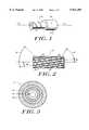
- FIG. 1is a side view, partially broken away, of a composite coiled tube constructed according to the invention that includes a liner and a composite layer;
- FIG. 2is a side view of a flattened out composite layer, constructed according to the invention, that has triaxially braided fiber components and which is suitable for constructing the composite layer of the composite tube shown in FIG. 1;
- FIG. 3is a cross-sectional view of the composite coiled tube having an inner liner surrounded by multiple composite layers;
- FIG. 4is a side view, partially broken away, of a composite coiled tube constructed according to the invention having a liner, an interface layer, and a composite layer;
- FIG. 5is a side view, partially broken away, of a composite coiled tube constructed according to the invention having a liner, an interface layer, a composite layer, and a pressure barrier;
- FIG. 6is a side view, partially broken away, of a composite coiled tube constructed according to the invention that includes a liner, an interface layer, a composite layer, a pressure barrier, and an outer protective layer;
- FIG. 7is a side view, partially broken away, of a composite coiled tube constructed according to the invention that includes a liner, a composite layer, and a pressure barrier;
- FIG. 8is a side view, partially broken away, of a composite coiled tube constructed according to the invention comprising a liner, an inner composite layer, a pressure barrier, and an outer composite layer;
- FIG. 9is a side view, partially broken away, of a composite coiled tube constructed according to the invention that includes an energy conductor;
- FIG. 10Ais a cross-sectional view of the composite tube of FIG. 9 having an axially extending energy conductor embedded in the liner;
- FIG. 10Bis a cross-sectional view of the composite tube of FIG. 9 having an axially extending energy conductor embedded in the composite layer;
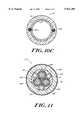
- FIG. 10Cis a cross-sectional view of the composite tube of FIG. 9 having an axially extending energy conductor embedded between the liner and the composite layer;
- FIG. 11is a cross-sectional view of the composite tube of FIG. 9 having a composite layer enclosing the liner and the energy conductor;
- FIG. 12illustrates the bending events that occur when running coiled tubing in and out of a well bore.
- Composite fibers(graphite, Kevlar, fiberglass, boron, etc.) have numerous assets including high strength, high stiffness, light-weight, etc., however, the stress strain response of composite fibers is linear to failure and therefore non ductile.
- Composite coiled tubingmust therefore address the strain limitations in another manner, i.e., by providing a construction to meet the requirements with a near elastic response or with large deformations of the matrix.
- Such a composite arrangementmust have high resistance to bending stresses and internal pressure and external pressure. It must also have high axial stiffness, high tensile and compressive strength and be resistant to shear stress. All of these properties are combined in the composite tubular member of the invention to provide a coiled tubing which can be bent to a radius compatible with winding onto a reasonable size spool.
- Fiber-Reinforced CompositesMaterials manufacturing and Design
- Fiber-reinforced composite materialsconsist of fibers of high strength and modulus embedded in or bonded to a matrix with distinct interfaces (boundary) between them.
- fibersare the principal load-carrying member, while the surrounding matrix keeps them in the desired location and orientation, acts as a load transfer medium between them, and protects them from environmental damages due to elevated temperatures and humidity, for example.
- compositesas used in this invention with the fibers selected from a variety of available materials including carbon, aramid, and glass and the matrix or resin selected from a variety of available materials including thermoset resin such as epoxy and vinyl ester or thermoplastic resins such as polyetheretherketone (PEEK), polyetherketoneketone (PEKK), nylon, etc.
- thermoset resinsuch as epoxy and vinyl ester
- thermoplastic resinssuch as polyetheretherketone (PEEK), polyetherketoneketone (PEKK), nylon, etc.
- PEEKpolyetheretherketone
- PEKKpolyetherketoneketone
- Composite structuresare capable of carrying a variety of loads in combination or independently, including tension, compression, pressure, bending, and torsion.
- hosea flexible tube for conveying fluids.
- a hoseis distinctly different from a composite tube.
- Hose productssuch as umbilical lines used in subsea application are constructed of high strength fibers such as aramid, dacron, or nylon laid down in a geodesic pattern onto a substrate plastic liner tubular structure.
- a hosemay be constructed of high strength fibers with a low modulus binder such as rubber.
- a hoseis designed to carry pressure loads and to exhibit good bending flexibility, but a hose has very limited ability to carry compressive, tension and torsion loads or external pressure.
- the composite tube described in this inventioncannot only carry high internal pressure but can also carry high compressive, tension and torsion loads, independently or in combination. Such capability is essential if the tubing is to be used for applications such as coiled tubing in which the tubing is pushed into a high pressure reservoir and to overcome the friction to movement within the well bore, especially for highly deviated or horizontal wells.
- the tubeis required to carry its own weight as it is suspended for 20,000-feet or more in a well bore and to be able to have high pulling capability to extract tools or to overcome being struck from sand and circulating solids which have collapsed around the tube. Such loads in the case of coiled tubing in deep wells can be in excess of 20,000 pounds.
- tubingIn other applications the tubing must also be capable of carrying high torsion loads. It was not considered feasible until the development represented in the current patent application, that one could design and build a composite tube capable of being bent to a relatively small diameter such as required for coiled tubing spooling and simultaneously be capable of carrying internal pressure and other loads.
- pultrusionfibers are drawn through a resin impregnating apparatus, then through dies to provide the desired shape. Alternatively, the resin may be injected directly within the die. Heat forming and curing structures are provided in conjunction with the dies.
- fiber windingthe various layers forming the composite structure are each formed by winding or wrapping fibers and a polymer matrix around a mandrel or some other underlying structure that provide a desired shape. Successive composite layers can then be applied to underlying composite layers.
- a triaxial braiding structurecan be manufactured using the fiber winding techniques disclosed in Quigley, U.S. Pat. Nos. 5,188,872 and in Quigley, RE 35,081.
- FIG. 1illustrates a composite coiled tube 10 constructed of an inner liner 12 and a composite layer 14.
- the composite coiled tubeis generally formed as a member elongated along axis 17.
- the coiled tubecan have a variety of tubular cross-sectional shapes, including circular, oval, rectangular, square, polygonal and the like.
- the illustrated tubehas a substantially circular cross-section.
- Liner 12serves as a pressure containment member to resist leakage of internal fluids from within the composite coiled tube 10.
- the liner 12is metallic, and in an alternative embodiment the liner 12 is formed of polymeric materials having an axial modulus of elasticity exceeding 100,000 psi.
- a liner having a modulus exceeding 100,000 psiis preferable as it is indicative of a tube capable of carrying high axial tension that does not cause the tube to compress or break.
- a liner with an axial modulus of elasticity less than 500,000 psiadvantageously allows the liner to bend, rather than pull away from the composite layer, as the composite tube is spooled or bent around a reel.
- the metals forming the linercan include, individually or in combination, steel, copper, or stainless steel.
- the polymeric materials making up the liner 12can be thermoplastic or thermoset materials.
- the linercan be formed of homo-polymers, co-polymers, composite polymers, or co-extruded composite polymers. Homo-polymers refer to materials formed from a single polymer, co-polymers refers to materials formed by blending two or more polymers, and composite polymers refer to materials formed of two or more discrete polymer layers that have been permanently bonded or fused.
- the polymeric materials forming the inner linerare preferably selected from a group of various polymers, including but not limited to: polyvinylidene fluoride, etylene tetrafluoroethylene, cross-linked polyethylene ("PEX"), polyethylene, and polyester.
- Further exemplary thermoplastic polymersinclude materials such as polyphenylene sulfide, polyethersulfone, polyethylene terephthalate, polyamide, polypropylene, and acetyl.
- Liner 12can also include fibers to increase the load carrying strength of the liner and the overall load carrying strength of the spoolable composite tube 10.
- Exemplary composite fibersinclude graphite, kevlar, fiberglass, boron, and polyester fibers, and aramid.
- the liner 12can be formed to be resistive to corrosive chemicals such as heterocyclic amines, inorganic sulfur compound, and nitrogenous and acetylenic organic compounds.
- corrosive chemicalssuch as heterocyclic amines, inorganic sulfur compound, and nitrogenous and acetylenic organic compounds.
- Three types of liner materialpolyvinylidene fluoride (“PVDF”), etylene tetrafluoroethylene (“ETFE”), and polyethylene (“PE”), have been found to meet the severe chemical exposure characteristics demanded in particular applications involving composite coiled tubing.
- PVDFpolyvinylidene fluoride
- ETFEetylene tetrafluoroethylene
- PEpolyethylene
- Two particularly attractive materials for the linerare the RC10-089 grade of PVDF, manufactured by Atochem, and Tefzel® manufactured DuPont.
- the linercomprises co-polymers formed to achieve enhanced liner characteristics, such as corrosion resistance, wear resistance and electrical resistance.
- a liner 12can be formed of a polymer and an additive such that the liner has a high electrical resistance or such that the liner dissipates static charge buildup within the composite tube 10.
- carbon blackcan be added to a polymeric material to form a liner 12 having a resistivity on the order of 10 8 ohms/centimeter.
- the carbon black additiveforms a liner 12 having an increased electrical conductivity that provides a static discharge capability.
- the static discharge capabilityadvantageously prevents the ignition of flammable fluids being circulated within the composite coiled tube 10.
- the liner 12has a mechanical elongation of at least 25%.
- a liner with a mechanical elongation of at least 25%can withstand the increased bending and stretching strains placed upon the liner as it is coiled onto a reel and inserted into and removed from various well bores. Accordingly, the mechanical elongation characteristics of the liner prolong the overall life of the composite coiled tube 10.
- the liner 12preferably has a melt temperature of at least 250° Fahrenheit so that the liner is not altered or changed during the manufacturing process for forming the composite coiled tubing.
- a liner having these characteristicstypically has a radial thickness in the range of 0.02-0.25 inches.
- the linercan act as a vehicle for transmitting chemicals that act upon the interior of the well bore, and the liner can also provide a conduit for transmitting fluids that power or control machines operably coupled with the composite tube.
- the liner diameteris typically less than 1/2 inch.
- the diameter of the linercan vary, as can the number of liners within the composite tube.
- the linercan include a plurality of tubes for transmitting different fluids through the composite tube.
- the composite layer 14can be formed of a number of plies, each ply having a fibers disposed with a matrix, such as a polymer, resin, or thermoplastic.
- the fiberstypically comprise structural fibers and flexible yarn components.
- the structural fibersare formed of either carbon, nylon, polyester, aramid, thermoplastic, or glass.
- the flexible yarn components, or braiding fibersare formed of either nylon, polyester, aramid, thermoplastic, or glass.
- the fibers included in layer 14can be woven, braided, knitted, stitched, circumferentially wound, or helically wound. In particular, the fibers can be biaxially or axially braided.
- the composite layer 14can be formed through pultrusion processes, braiding processes, or continuous filament winding processes.
- a tube formed of the liner 12 and the composite layer 14form a composite tube having a maximum tensile strain of at least 0.25 percent and being capable of maintaining an open bore configuration while being spooled on a reel.
- the liner 12, illustrated in FIG. 1,can also include grooves 15 or channels on the exterior surface of the liner.
- the groovesincrease the bonding strength between the liner 12 and the composite layer 14 by supplying a roughened surface for the fibers in the composite layer 14 to latch onto.
- the groovescan further increase the bonding strength between the liner 12 and the composite layer 14 if the grooves are filled with a matrix.
- the matrixacts as a glue, causing the composite layer to be securely adhered to the underlying liner 12.
- the groovesare helically oriented on the liner relative to the longitudinal axis 17.
- FIG. 2shows a "flattened out” view of a preferred composite layer 14 having a fiber component 20 interwoven with a plurality of like or different fiber components, here shown as a clockwise helically oriented fiber component 16 and a counterclockwise helically oriented fiber component 18.
- the configuration of layer 14 shown in FIG. 2is appropriately denoted as a "triaxially braided" ply.
- the fiber components 16, 18, 20are suspended in a matrix 22.
- Helically oriented fibersare fibers that follow a spiral path.
- helical fibersspiral around a mandrel underlying the composite tube or they spiral around underlying layers of the composite tube.
- a helically oriented fiberfollows a path comparable to the grooves around the shaft of a common screw.
- a helical fibercan be described as having an axial vector, an angle of orientation, and a wrapping direction. The axial vector indicates that the helical fiber can follow a path along the length of the tube 10 as it spirals around the tube, as opposed to a fiber that continually wraps around a particular section of the tube 10 without extending along the length of the tube.
- the angle of orientation of the helical fiberindicates the helical fiber's angle relative to a defined axis, such as the longitudinal axis 17.
- a helical fiber having an angle of 0 degreesis a fiber that extends parallel to the longitudinal axis and that does not wrap around the tube 10, while a fiber having an angle of 90 degrees circumferentially wraps around the tube 10 without extending along the length of the tube.
- the wrapping direction of the helical fiberis described as either clockwise or counter-clockwise wrapping around the tube 10.
- the fiber componentscan be formed of carbon, glass, aramid (such as kevlar® or twaron®), thermoplastic, nylon, or polyester.
- fibers 16 and 18act as braiding fibers and are formed of either nylon, polyester, aramid, thermoplastic, or glass.
- Fiber 20acts as a structural fiber and is formed of either carbon, glass, or aramid. Fiber 20 increases the axial strength of the composite layer 14 and the spoolable tube 10.
- the matrix material 22is generally a high elongation, high strength, impact resistant polymeric material such as epoxy.
- Other alternative matrixesinclude nylon-6, vinyl ester, polyester, polyetherketone, polyphenylen sulfide, polyethylene, polypropylene, and thermoplastic urethanes.
- Fiber 20extends helically or substantially axially relative to the longitudinal axis 17.
- the helically oriented fiber component 16 and 18tend to tightly bind the longitudinal fiber component 20 with the matrix material 22 in addition to providing increased bending stiffness along axis 17 and increased tortional strength around axis 17.
- the helically oriented fiber components 16 and 18can be interwoven amongst themselves. To this end, successive crossings of two fiber components 16 and 18 have successive "over” and "under” geometries.
- the composite layerincludes a triaxial braid that comprises an axially extending fiber component 20, a clockwise extending second fiber component 16 and a counter-clockwise extending third fiber component 18, wherein the fiber 20 is interwoven with either fiber 16 or fiber 18.
- a single braiding fibersuch as fiber 16 binds the fiber component of a given ply together by interweaving the braiding fiber 16 with itself and with the axially extending fiber 20.
- a fiberis interwoven with itself, for example, by successively wrapping the fiber about the member and looping the fiber with itself at each wrap.
- axially extending structural fiber 20is oriented relative to the longitudinal axis 17 at a first angle 28.
- fiber 20is helically oriented at the first angle 28 relative to the longitudinal axis 17.
- the first angle 28can vary between 5°-20°, relative to the axis.
- the first angle 28can also vary between 30°-70°, relative to the axis 17. Although it is preferred to have fiber 20 oriented at an angle of 45° relative to axis 17.
- the braiding fiber 16is oriented relative to structural fiber 20 at a second angle 24, and braiding fiber 18 is oriented relative to structural fiber 20 at a third angle 26.
- the angle of braiding fibers 16 and 18, relative to structural fiber 20,may be varied between + ⁇ -10° and + ⁇ -60°. In one aspect of the invention, fibers 16 and 18 are oriented at an angle of + ⁇ -20° relative to fiber 20.
- One failure mechanism of the composite tube during loadingis believed to be the development of micro-cracks in the resin and the introduction of microscopic defects between fibers.
- the development of some micro-cracksis also believed to be inevitable due to the severe loads placed on the tube during the manufacturing and bending of the tube.
- the effects of these micro-cracks and microscopic defectscan be retarded by restraining the growth and accumulation of the micro-cracks and microscopic defects during the manufacturing and use of the composite coiled tube.
- the applicantshave discovered that the selection of fibers 16 and 18 from the group of fibers consisting of nylon, polyester, glass and aramid mitigates and stops the growth of the microscopic defects.
- the selection of fibers 16 and 18 from the particularly noted materialsimproves the damage tolerance and fatigue life of the composite coiled tubing 10.
- the total volume of any particular fibrous material in any selected layer of the composite coiled tubeaffects the overall mechanical characteristics of the composite coiled tube 10, including a reduction in crack propagation. It additionally follows that the total volume of any particular fibrous material in the whole composite coiled tube also affects the mechanical characteristics of the composite coiled tube 10.
- a composite coiled tube having improved strength and durability characteristicsis obtained by forming a composite layer 14 wherein the combined fiber volume of the clockwise extending and counter-clockwise extending braiding fibers 16 and 18 constitute less than 20% of the total fiber volume in the composite layer 14.
- the fiber volume of the axially extending fiber 20should constitute at least 80% of the fiber volume of the composite layer 14.
- the first composite layer 14includes at least 80% by fiber volume of substantially continuous fibers oriented relative to the longitudinal axis 17 of the tube at an angle between 30-70 degrees.
- the volume of matrix in the layer 14typically accounts for 35% or more of the volume in the composite layer 14. Accordingly, the combined volume of all the fibers in composite layer 14 account for less than 65% of the volume of the composite layer 14. It is thus evident, that the volume of fibers 16 and 18 account for less than 13% of the total volume of the composite layer 14 and that the volume of fiber 20 accounts for at least 52% of the total volume of the composite layer 14.
- Matrix 20 in composite layer 14is selected such that transverse shear strains in the laminar can be accommodated without breaching the integrity of the coil composite tube 10.
- the strainsgenerally is the result of bending the spoolable composite tube over the reel. These strains do not impose significant axial stresses on the fiber, but they do impose significant stresses on the matrix 20. Accordingly, matrix 20 should be chosen such that the maximal tensile elongation is greater than or equal to 5%.
- the Applicanthas further shown that choosing a matrix having a tensile modulus of at least 100,000 psi adds to the ability of the coil composite tube to withstand excessive strain due to bending.
- the matrix 20also has a glass transition temperature of at least 180° Fahrenheit so that the characteristics of the resin are not altered during high temperature uses involving the coiled composite tube 10.
- the tensile modulus rating and the tensile elongation ratingsare generally measured as the coil composite tube is being manufactured at 70° Fahrenheit.
- Matrix materials having these characteristicsinclude epoxy, vinyl ester, polyester, urethanes, phenolics, thermoplastics such as nylon, polyropelene, and PEEK.
- FIG. 3illustrates a coiled composite tube 10 having an inner liner 12 and a first composite layer 14A, a second composite layer 14B, and a third composite layer 14C.
- Each of the composite layersis formed of fibers embedded in a matrix, and each of the composite layers successively encompasses and surrounds the underlying composite layer or liner 12.
- At least one of the composite layers, 14A, 14B, 14Cincludes a helically oriented fiber in a matrix.
- at least one of the composite layers 14A, 14B, 14Ccontains a ply as described in FIG. 2.
- one of the composite layers 14A, 14B, 14Chas a first helically extending fiber, a second clockwise extending fiber, and a third counterclockwise extending fiber wherein the first fiber is interwoven with at least one of the second and third fibers.
- the other two composite layerscontain fiber suspended in a matrix.
- the fiberscan be axially extending, circumferentially wrapped, or helically wrapped, biaxially braided or triaxially braided.
- the fibers in each of the composite layersare all selected from the same material.
- the fibers in each of the composite layersare all selected from the different materials.
- composite layer 14Acan comprise a triaxially braided ply having clockwise and counter-clockwise helically oriented fibers formed of polyester and having a helically extending fiber formed of glass
- composite layer 14Bcan comprise a ply having a circumferentially wound kevlar fiber
- composite layer 14Ccan comprise a triaxially braided ply having a clockwise and counter-clockwise helically oriented fibers formed of glass and having a helically extending fiber formed of carbon.
- one aspect of the inventionincorporates a composite layer 14A formed of carbon fibers and polyester fibers in a triaxially braided structure and a second composite layer 14B formed of kevlar fibers.
- the kevlar fiberscan be incorporated into either a conventional bi-axial braid, triaxial braid, or helical braid.
- the second composite layercan include two sets of aramid fibers biaxially braided together.
- the coiled composite tube 10having an inner composite layer 14A formed with carbon fibers and an exterior composite layer 14B formed with kevlar fibers provides a coiled composite tube having balanced strength in two directions and provides a coiled composite tube having a constricting force which helps restrain the local buckling of delaminated sublamina and subsequent delamination growth, thereby improving the fatigue resistance of the coiled composite tube 10.
- this aspect of the inventioncan include a third composite layer 14C external to the second composite layer 14B.
- the third composite layer 14Ccan, for instance, include a matrix and a fiber helically oriented relative to the longitudinal axis 17.
- the composite layer 14Acomprises a triaxially braided ply having an axially extending fiber formed of carbon and having a clockwise extending fiber and a counter-clockwise extending fiber both formed of polyester.
- the helically extending fiber 20is oriented at an 45° angle to the axis of the coiled composite tube 10.
- composite layer 14Bis triaxially braided and comprises a helically extending fiber formed of carbon and oriented at an angle of 45° relative to the axis 17 of coiled composite tube 10.
- Composite layer 14Bfurther includes a clockwise extending second fiber and a counter-clockwise extending third fiber formed of polyester.
- the third composite layer 14Cis biaxially braided, and comprises a kevlar fiber extending helically and oriented at a 54° angle to the axis 17 of the composite coiled tube 10.
- FIG. 4illustrates a composite coiled tube elongated along an axis 17 and having an inner liner 12, an interface layer 56, and a composite layer 14.
- the interface layer 56surrounds the liner 12 and is sandwiched between the liner 12 and the composite layer 14.
- the interface layer 56improves the bonding between the inner liner 12 and the composite layer 14.
- the liner 12be integrally attached to the composite layer 14.
- the necessity for a bonded lineris that in certain operating conditions experienced in down hole service, the external surface of the tube will be subjected to higher pressure than the interior of the tube. If the liner is not bonded to the composite layer 14 this external pressure could force the liner to buckle and separate from the composite layer such that the liner collapses.
- loading and bending of the tubemay introduce microscopic cracks in the composite layer 14 which could serve as microscopic conduits for the introduction of external pressure to be applied directly to the outer surface of the liner 12. Once again, these external pressures could cause the liner 12 to collapse.
- the interface layer 56provides a mechanism for bonding the liner 12 to the composite layer 14 such that the liner does not collapse under high external pressures. The interface layer 56 can also reduce cracking and the propagation of cracking along the composite layer 14 and liner 12.
- the interface layer 56comprises a fiber reinforced matrix where the fiber volume is less than 40% of the total volume of the interface layer 56.
- the matrix and the fiber forming interface layer 56predominately act as an adhesive layer that bonds the liner 12 to the composite layer 14.
- the fibers within the interface layer 56can be oriented in various ways, including a woven or non-woven structure.
- the fibers within the interface layer 56are polyester fibers.
- An interface layer having this structureis able to prevent the liner from separating from the composite layer even when the differential pressure between the exterior and interior of the tube 10 exceeds 1,000 psi.
- the matrix within the interface layer 56can comprise a filled polymeric layer or an unfilled polymeric layer.
- a filled polymeric layeruses a polymeric matrix having additives that modify the properties of the polymeric layer.
- the additives used in the filled polymeric layerinclude particulates and fibers. For instance, carbon black powder can be added to the polymeric layer to increase the conductivity of the interface layer 56, or chopped glass fibers can be added to the polymeric layer to increase the stiffness of the interface layer 56.
- the interface layerhas an axial modulus of elasticity that lies between the modulus of the elasticity of the liner 12 and the modulus of elasticity of the composite layer 14.
- the interface layer 56thus has a modulus of elasticity that transitions between the modulus of elasticity of the liner 12 and the composite layer 14.
- the interface layer 56furthermore increases the fatigue life of the coiled composite tube 10.
- the structure of the interface layer 56achieves this by dissipating shear stress applied along the length of the coiled composite tube 10. By dissipating the shear, the interface layer reduces cracking and the propagation of cracks along the composite layer 14.
- FIG. 5illustrates a composite coiled tube elongated along an axis 17 and having an inner liner 12, an interface layer 56, a composite layer 14, and a pressure barrier layer 58.
- the pressure barrier layer 58prevents gases or liquids (i.e. fluids) from penetrating into the composite coiled tube 10.
- a fluid that penetrates through the tube 10 to liner 12can build up to a sufficient level of pressure capable of collapsing the liner 12.
- a fluid that penetrates the coiled composite tube 10 during exposure in the well bore 36may outgas when the coil composite tube 10 is returned to atmospheric pressure.
- a coiled composite tube 10can function effectively without a pressure barrier layer 58 under certain conditions.
- a pressure barrier layeris not necessary.
- the pressure barrier layer 58is preferred. As illustrated in FIG. 5, the pressure barrier layer 58 generally is positioned outside of the composite layer 14.
- the pressure barrier layer 58can be formed of a metal, thermoplastic, thermoset films, or an elastomer such as a rubber sheet. All these various materials can function as a pressure barrier because they substantially prevent the diffusion of fluids. Preferable properties of the pressure barrier layer include low permeability to fluids (i.e., gases or liquids), high elongation, and bondability to composite layer 14. It is also preferred that the pressure barrier layer 58 have a maximum tensile elongation of 10% and an axial modulus of elasticity of less than 750,000 psi. These values of tensile elongation and modulus of elasticity are measured at 70° Fahrenheit during the manufacturing of the coiled composite tube 10. The permeability of the pressure barrier layer should be less than 0.4 ⁇ 10 to the -10 ccs per sec-cm 2 -cm-cmhg.
- the impermeable pressure barrier layer 58can be formed of an impermeable films formed of metals or polymers.
- acceptable polymeric filmsinclude films formed of polyester, polyimide, polyamide, polyvinyl fluoride, polyvinylidene fluoride, polyethylene, and polypropylene, or other thermoplastics.
- the impermeable film of layer 58can be a seamless polymer layer which is coextruded or formed via a powder deposition process.
- the impermeable filmcan be helically wrapped or circumferentially wrapped around the composite layer to form an overlapping and complete barrier. That is, the fiber or material forming the pressure barrier layer must be wrapped in such a fashion that no gaps exist and the pressure barrier layer 58 is sealed.
- a fused particle coatingis formed by grinding a polymeric material into a very fine powder. The fine power is then heat-fused onto the other materials forming the pressure barrier layer 58 or onto the underlying composite layer 14.
- FIG. 6illustrates a composite coiled tube elongated along an axis 17 and having an inner liner 12, an interface layer 56, a composite layer 14, a pressure barrier layer 58 and an outer protective layer 60.
- the interface layer 56enhances the bond between the composite layer 14 to the inner liner 12.
- the pressure barrier layer 58prevents fluids from penetrating into the composite coiled tube 10.
- the outer protective layer 60provides wear resistance, impact resistance, and an interface layer for the coupling for the coiled composite tube 10.
- the protective layeris positioned such that it surrounds the pressure barrier 58.
- Outer protective layer 60provides abrasion resistance and wear resistance by forming an outer surface to the coil composite tube that has a low co-efficient of friction thereby causing objects to slip off the coiled composite tube.
- the outer protective layer 60provides a seamless layer for holding the inner layers of the coiled composite tube together.
- the outer protective layercan be formed of a filled or unfilled polymeric layer.
- the outer protective layer 60can be formed of a fiber, such as kevlar or glass, and a matrix.
- the fibers of the outer protective layer 60can be woven in a mesh or weave pattern around the inner layers of the coiled composite tube 10, or the fibers can be braided or helically braided around the inner layers of tube 10. In either case, the fibers in the outer protective layer are wrapped helically around the inner layers of the coiled composite tube 10 in order to provide a seamless structure.
- particlescan be added to the outer protective layer to increase the wear resistance of the outer protective layer 60.
- the particles usedcan include any of the following, individually or in combination with one another: ceramics, metallics, polymerics, silicas, or fluorinated polymers. Adding Teflon® (MP 1300) particles and an aramid powder (PD-T polymer) to the matrix of the outer protective layer 60 has been found to be one effective way to reduce friction and enhance wear resistance.
- the particles added to the outer protective layer 60are such that they consist of less than 20% by volume of the matrix.
- a particulatesuch as Teflon® MP 1300 can also be added to the polymeric protective layer.
- the particlestypically comprise less than 60% by coating volume of the outer wear resistant layer 60,
- FIG. 7illustrates an embodiment of the composite coiled tube elongated along an axis 17 and having a liner 12, a composite layer 14, and a pressure barrier 58.
- FIG. 7is similar to FIG. 5, except that it lacks the interface layer 56.
- the inner liner 12is positioned internally to the composite layer 14, and the composite layer 14 is positioned internally to the pressure barrier 58.
- This figureillustrates, among other things, that the interface layer 56 can either be included or removed from all embodiments of the invention, depending upon whether the circumstances require the use of an interface layer to increase the bonding strength between the liner and the composite layer.
- FIG. 8illustrates another embodiment of a composite coiled tube elongated along an axis 17, the composite tube includes a liner 12, a first composite layer 14, a pressure barrier 58, and a second composite layer 14'.
- the first composite layer 14surrounds the internal liner
- the pressure barriersurrounds the first composite layer 14.
- the second composite layer 14'surrounds the pressure barrier 58.
- the pressure barrieris sandwiched between two composite layers 14 and 14'.
- Composite layer 14'can be structured in any manner that composite layer 14 can be structured, but the layers 14 and 14' need not be identical. In addition, either composite layer 14 or composite layer 14' can include multiple composite layers as illustrated in FIG. 3. The external composite layer 14' proves useful in providing an exterior surface capable of engaging a coupling device.
- the external composite layer 14'can also be fashioned to act as an outer protective layer capable of providing abrasion resistance and wear resistance. This can be achieved by forming the external composite layer 14' from a filled or unfilled polymeric layer. The layer 14' can also achieve increased abrasion and wear resistance by helically wrapping or braiding those fibers forming composite layer 14' around the inner layers of the tube 10. Furthermore, the external composite layer 14' can be fashioned to reduce the friction of the exterior of tube 10 by adding particles to the external composite layer 14'. The particles can include ceramics, metallics, polymerics, silicas, or fluorinated polymers.
- FIG. 9illustrates a composite coiled tube elongated along an axis 17 wherein the composite tube includes a liner 12, a composite layer 14, and an energy conductor 62 forming part of the composite layer 14.
- the energy conductorprovides a path for passing power, communication or control signals from the surface down through the tube to a machine attached to the end of the tube.
- the energy conductor 62can be either a hydraulic medium, a pneumatic medium, an electrical medium, an optical medium, or any material or substance capable of being modulated with information data or power.
- the energy conductorcan be a fluid impermeable tube for conducting hydraulic or pneumatic energy along the length of the composite tube.
- the hydraulic or pneumatic energycan be used to control or power the operation of a machine, such as a submersible pump, operably coupled to the composite tube.
- the energy conductorcan be an electrically conductive medium, such as copper wire, for transmitting a control or power signal to a machine operably coupled to the composite tube.
- the energy conductoralso includes optical medium, such as fiber optics, for transmitting an optical signal along the composite tube.
- the composite tubecan include one or more of the described energy conductors.
- the hydraulic control line embodiment of the energy conductor 62 used in the composite tube 10can be either formed of metal or of a polymeric material.
- the metals forming the hydraulic linecan include, individually or in combination, steel, copper, or stainless steel. Hydraulic control lines typically have a diameter less than 1/2 an inch.
- the polymeric materials making up the hydraulic linecan be thermoplastic or thermoset materials.
- the hydraulic linecan be formed of homo-polymers, co-polymers, composite polymers, or co-extruded composite polymers.
- the polymeric materials forming the hydraulic lineare preferably selected from a group of various polymers, including but not limited to: polyvinylidene fluoride, etylene tetrafluoroethylene, cross-linked polyethylene ("PEX"), polyethylene, and polyester.
- Further exemplary thermoplastic polymersinclude materials such as polyphenylene sulfide, polyethersulfone, polyethylene terephthalate, polyamide, polypropylene, and acetyl.
- the hydraulic linecan also include fibers to increase the load carrying strength of the hydraulic line and the overall load carrying strength of the spoolable composite tube 10.
- Exemplary composite fibersinclude graphite, kevlar, fiberglass, boron, and polyester fibers, and aramid.
- the hydraulic line embodiment of the energy conductor 62can be formed to be resistive to corrosive chemicals such as heterocyclic amines, inorganic sulfur compound, and nitrogenous and acetylenic organic compounds.
- corrosive chemicalssuch as heterocyclic amines, inorganic sulfur compound, and nitrogenous and acetylenic organic compounds.
- PVDFpolyvinylidene fluoride
- ETFEetylene tetrafluoroethylene
- PEpolyethylene
- Two particularly attractive materials for the hydraulic lineare the RC10-089 grade of PVDF, manufactured by Atochem, and Tefzel® manufactured DuPont.
- the hydraulic line embodiment of the energy conductor 62comprises co-polymers formed to achieve enhanced characteristics, such as corrosion resistance, wear resistance and electrical resistance.
- a hydraulic linecan be formed of a polymer and an additive such that the hydraulic line has a high electrical resistance or such that the hydraulic line dissipates static charge buildup within the composite tube 10.
- carbon blackcan be added to a polymeric material to form a hydraulic line having a resistivity on the order of 10 8 ohms/centimeter.
- the energy conductor 62can be located in either the liner, the composite layers, or the pressure barrier forming the tube 10. But is preferable to locate the energy conductors in those layers nearest the interior surface of the tube and not in those layers located near the exterior surface of the tube. If an energy conductor is located near the exterior surface of the tube it is more likely to be subjected to corrosive surfaces or materials located outside the tube 10. In addition, an energy conductor located near the interior of the tube 10 will be subjected to smaller bending strains when compared to an energy conductor located near the exterior of the tube.
- An energy conductorcan be embedded in any of the layers forming the tube 10 using the same methods known in the art for adding a fiber to the composite layer.
- the energy conductorcan be either embedded in: the liner; the composite layer; or between the liner and the composite layer.
- both the energy conductor and the linercan be surrounded by the composite layer.
- an energy conductoris wound onto a mandrel or any underlying structure while applying a matrix.
- Energy conductorscan also be added to a fiber composite layer with a pultrusion process.
- the energy conductorcan be drawn through a resin impregnating apparatus, then through dies to provide the desired shape.
- a primary concern in placing the conductor 62 in the inner areas of the composite tube 10is to ensure that the bending strains on the conductor 62 are minimized. This is particularly critical if the conductor 62 is a fiber optic cable.
- the energy conductor 62can be helically oriented relative to the longitudinal axis 17 of the composite tube to minimize the bending strain on conductor 62.
- the helical orientationallows the compression strain experienced by the section of the conductor located on the interior bend of the tube to be offset by the expansion strain experienced by the section of the conductor located on the exterior bend of the tube. That is, the conductor 62 is able to substantially distribute the opposing strains resulting from the bending action of the composite tube across the length of the conductor 62, thereby preventing irreparable damage to the conductor.
- FIG. 10Ais a cross-sectional view of the composite tube 10 having an axially extending energy conductor 62 embedded in the liner 12.
- the conductor 62solely in the liner, bumps in the outer diameter of the composite tube potentially formed by the conductor 62 are eliminated.
- the addition of the conductors 62 to the composite tubecan cause bumps or ripples in the outer diameter of the composite tube as additional layers of material are added over the conductors.
- These bumpscan be substantially eliminated by embedding the conductor 62 in a liner formed of a polymeric material. When formed of a polymeric, the liner envelopes the conductors and cures in a form that retains a uniform outer diameter.
- the conductorscan be positioned within the composite tube so that they extend parallel to the axis of the composite tube 10. By orienting the conductor axially along the length of the tube 10, the conductors increase the composite tube's axial stiffness and tensile strength. The effect can be increased by orienting a plurality of conductors 62, 62' axially along the length of the tube 10.
- the conductors 62, 62'can be oriented so that they are diametrically opposed.
- This configuration of the composite tube 10creates a major and minor moment of inertia where the conductors 62, 62' are located in a neutral bending axis.
- the configurationforces a preferred direction of bending upon the tube 10.
- the composite tube 10has a preferred direction for winding onto a spool by bending about the minor moment of inertia.
- the advantage of this configurationis that high stiffness and high strength material can be placed in the inner section of the composite tube 10 without significant increase in the associated bending strains or sacrifice in the minimum radius of curvature permitted for spooling.
- the placement of the conductors 62, 62' on the neutral bending axisminimizes the bending strains on the conductors, thereby minimizing bending damage to the conductors.
- FIG. 10Bis a cross-sectional view of the composite tube 10 having an axially extending energy conductor 62 embedded in the composite layer 14. Locating the energy conductors in the fiber composite layer may prove advantageous when the liner 12 is formed of metal. In addition, it typically proves easier to manufacture a composite tube with the energy conductors embedded in the composite layer 14, rather than being embedded in the liner 12.
- FIG. 10Cis a cross-sectional view of the composite tube 10 having an axially extending energy conductor 62 embedded between the liner 12 and the composite layer 14.
- FIG. 11is a cross-sectional view of the composite tube 10 having the energy conductor 62 and the liner 12 enclosed within the composite layer 14.
- This aspect of the inventionproves particularly important when multiple energy conductors, as shown in FIG. 11, are required. Designs having multiple energy conductors, or having energy conductors with large diameters, require much of the space within the composite tube for the placement of the energy conductors. As a result, it becomes less desirable to embed the energy conductors directly in either the liner or the composite layer. Accordingly, the energy conductors and the liner are both surrounded by the composite layer.
- the composite layercan be enclosed within a pressure barrier 58 and within an outer protective layer 60.
- the spaces formed between the energy conductor and the linerare filled with a fill material 66.
- the spacesarise when the energy conductor and the liner do not completely fill the channel within the composite layer 14.
- the fill materialcan be formed of a polymeric material, such as a thermoset or thermoplastic.
- the polymeric materialcan be formed of co-polymers, homo-polymers, or composite polymers.
- the fill materialcan include fibers for added structural strength.
- the fill materialbinds the energy conductors and the liner to the composite layer.
- the fill materialprovides structural support to the energy conductors and the liner.
- FIG. 11also shows an insulating sheath surrounding the energy conductor 62.
- the insulating sheathinsulates the energy conductor from detrimental external conditions.
- the insulating sheath 64electrically insulates the energy conductor.
- the insulating sheathcan also be fluid impermeable for protecting an underlying electrical conductor from the corrosive effects of external fluids or gases.
- the insulating sheathprovides an opaque surface for preventing the distortion of optical signals within the energy conductor 62.
- the energy conductorscan include a plurality of energy conductors for powering a machine operably coupled to the coiled tube.
- the composite tube 10can include three electrical energy conductors that provide a primary line, a secondary line, and a tertiary line for electrically powering a machine using a three-phase power system.
- the composite tube 10can also include a plurality of liners for transmitting fluids along the length of the tube 10.
- FIG. 12illustrates the bending cycles that a coiled composite tube 10 is subjected to when performing a typical coiled tubing service.
- the tubing 10is inserted and removed from a well bore 36 located below the ground surface.
- a reel 42is provided on the surface and the composite coiled tube 10 is stored on the reel 42.
- An injector assembly 38is located on the surface over the well bore 36.
- Injector assembly 38typically contains a roller belt 40 used to guide the coiled composite tube 10 through the injector assembly 38 into the well bore 36.
- the coiled composite tube 10typically is subjected to six bending events as it is inserted and removed from the well bore 36.
- the first bending event 44takes place when the coiled composite tube 10 is pulled off the service reel 42.
- the coiled composite tube 10passes through two bending events 46 and 48.
- the bending events 50, 52 and 54are the reverse of bending events 44, 46, 48 and occur as the coiled composite tube 10 is extracted from the well bore 36.
- the insertion and extraction of the tube 10thus results in a total of six bending events for every round trip of the coiled composite tube 10.
- the current steel tubing being used in the fieldcan generally be cycled three times through the bending events described in FIG. 4 in conjunction with high internal pressures before the steel tubing fails.
- the coiled composite tube of the Applicant's inventioncan be cycled 10,000 times through the bending events described in FIG. 4.
Landscapes
- Engineering & Computer Science (AREA)
- General Engineering & Computer Science (AREA)
- Mechanical Engineering (AREA)
- Life Sciences & Earth Sciences (AREA)
- Mining & Mineral Resources (AREA)
- Geology (AREA)
- Geochemistry & Mineralogy (AREA)
- Environmental & Geological Engineering (AREA)
- Fluid Mechanics (AREA)
- Physics & Mathematics (AREA)
- General Life Sciences & Earth Sciences (AREA)
- Textile Engineering (AREA)
- Manufacturing & Machinery (AREA)
- Rigid Pipes And Flexible Pipes (AREA)
- Earth Drilling (AREA)
- Developing Agents For Electrophotography (AREA)
- Diaphragms For Electromechanical Transducers (AREA)
- Dry Formation Of Fiberboard And The Like (AREA)
Abstract
Description
Claims (67)
Priority Applications (15)
| Application Number | Priority Date | Filing Date | Title |
|---|---|---|---|
| US08/804,790US5921285A (en) | 1995-09-28 | 1997-02-24 | Composite spoolable tube |
| AU61797/98AAU6179798A (en) | 1997-02-24 | 1998-02-23 | Composite spoolable tube |
| GB9920058AGB2338736B (en) | 1997-02-24 | 1998-02-23 | Composite spoolable tube |
| CA002282358ACA2282358C (en) | 1997-02-24 | 1998-02-23 | Composite spoolable tube |
| PCT/US1998/003413WO1998037303A1 (en) | 1997-02-24 | 1998-02-23 | Composite spoolable tube |
| JP53692398AJP2001512542A (en) | 1997-02-24 | 1998-02-23 | Rollable composite tube |
| US09/295,289US6148866A (en) | 1995-09-28 | 1999-04-20 | Composite spoolable tube |
| NO19994045ANO322592B1 (en) | 1997-02-24 | 1999-08-23 | Flushable composite |
| US09/597,201US6286558B1 (en) | 1995-09-28 | 2000-06-20 | Composite spoolable tube |
| US09/875,561US6357485B2 (en) | 1995-09-28 | 2001-06-06 | Composite spoolable tube |
| US10/041,247US6604550B2 (en) | 1995-09-28 | 2002-01-08 | Composite spoolable tube |
| US10/460,768US6857452B2 (en) | 1995-09-28 | 2003-06-12 | Composite spoolable tube |
| US10/997,453US7647948B2 (en) | 1995-09-28 | 2004-11-24 | Composite spoolable tube |
| US12/629,683US8066033B2 (en) | 1995-09-28 | 2009-12-02 | Composite spoolable tube |
| US13/277,657US8678042B2 (en) | 1995-09-28 | 2011-10-20 | Composite spoolable tube |
Applications Claiming Priority (3)
| Application Number | Priority Date | Filing Date | Title |
|---|---|---|---|
| US445295P | 1995-09-28 | 1995-09-28 | |
| US08/720,029US6016845A (en) | 1995-09-28 | 1996-09-27 | Composite spoolable tube |
| US08/804,790US5921285A (en) | 1995-09-28 | 1997-02-24 | Composite spoolable tube |
Related Parent Applications (1)
| Application Number | Title | Priority Date | Filing Date |
|---|---|---|---|
| US08/720,029Continuation-In-PartUS6016845A (en) | 1995-09-28 | 1996-09-27 | Composite spoolable tube |
Related Child Applications (1)
| Application Number | Title | Priority Date | Filing Date |
|---|---|---|---|
| US09/295,289ContinuationUS6148866A (en) | 1995-09-28 | 1999-04-20 | Composite spoolable tube |
Publications (1)
| Publication Number | Publication Date |
|---|---|
| US5921285Atrue US5921285A (en) | 1999-07-13 |
Family
ID=25189843
Family Applications (8)
| Application Number | Title | Priority Date | Filing Date |
|---|---|---|---|
| US08/804,790Expired - LifetimeUS5921285A (en) | 1995-09-28 | 1997-02-24 | Composite spoolable tube |
| US09/295,289Expired - LifetimeUS6148866A (en) | 1995-09-28 | 1999-04-20 | Composite spoolable tube |
| US09/597,201Expired - LifetimeUS6286558B1 (en) | 1995-09-28 | 2000-06-20 | Composite spoolable tube |
| US09/875,561Expired - LifetimeUS6357485B2 (en) | 1995-09-28 | 2001-06-06 | Composite spoolable tube |
| US10/041,247Expired - LifetimeUS6604550B2 (en) | 1995-09-28 | 2002-01-08 | Composite spoolable tube |
| US10/460,768Expired - LifetimeUS6857452B2 (en) | 1995-09-28 | 2003-06-12 | Composite spoolable tube |
| US10/997,453Expired - Fee RelatedUS7647948B2 (en) | 1995-09-28 | 2004-11-24 | Composite spoolable tube |
| US12/629,683Expired - LifetimeUS8066033B2 (en) | 1995-09-28 | 2009-12-02 | Composite spoolable tube |
Family Applications After (7)
| Application Number | Title | Priority Date | Filing Date |
|---|---|---|---|
| US09/295,289Expired - LifetimeUS6148866A (en) | 1995-09-28 | 1999-04-20 | Composite spoolable tube |
| US09/597,201Expired - LifetimeUS6286558B1 (en) | 1995-09-28 | 2000-06-20 | Composite spoolable tube |
| US09/875,561Expired - LifetimeUS6357485B2 (en) | 1995-09-28 | 2001-06-06 | Composite spoolable tube |
| US10/041,247Expired - LifetimeUS6604550B2 (en) | 1995-09-28 | 2002-01-08 | Composite spoolable tube |
| US10/460,768Expired - LifetimeUS6857452B2 (en) | 1995-09-28 | 2003-06-12 | Composite spoolable tube |
| US10/997,453Expired - Fee RelatedUS7647948B2 (en) | 1995-09-28 | 2004-11-24 | Composite spoolable tube |
| US12/629,683Expired - LifetimeUS8066033B2 (en) | 1995-09-28 | 2009-12-02 | Composite spoolable tube |
Country Status (7)
| Country | Link |
|---|---|
| US (8) | US5921285A (en) |
| JP (1) | JP2001512542A (en) |
| AU (1) | AU6179798A (en) |
| CA (1) | CA2282358C (en) |
| GB (1) | GB2338736B (en) |
| NO (1) | NO322592B1 (en) |
| WO (1) | WO1998037303A1 (en) |
Cited By (167)
| Publication number | Priority date | Publication date | Assignee | Title |
|---|---|---|---|---|
| US6129962A (en)* | 1994-01-07 | 2000-10-10 | Exel Oyj | Sports implement and shaft having consistent strength |
| US6257332B1 (en) | 1999-09-14 | 2001-07-10 | Halliburton Energy Services, Inc. | Well management system |
| EP1143104A1 (en) | 2000-04-03 | 2001-10-10 | Airborne Development B.V. | A composite tube with embedded power conductors |
| US20020014340A1 (en)* | 2000-08-07 | 2002-02-07 | Johnson Ready J. | Composite pipe telemetry conduit |
| US6357485B2 (en)* | 1995-09-28 | 2002-03-19 | Fiberspar Corporation | Composite spoolable tube |
| US6361299B1 (en) | 1997-10-10 | 2002-03-26 | Fiberspar Corporation | Composite spoolable tube with sensor |
| US6364021B1 (en) | 2000-07-11 | 2002-04-02 | Halliburton Energy Services, Inc. | Well management system and method of operation |
| US6363974B1 (en) | 1999-11-05 | 2002-04-02 | Wellstream, Inc. | Flexible pipe and method of manufacturing same |
| US20020117228A1 (en)* | 2001-02-07 | 2002-08-29 | Tatsuo Nakajima | Fiber reinforced plastic pipe and power transmission shaft employing the same |
| US6446672B1 (en) | 1999-11-05 | 2002-09-10 | Wellstream, Inc. | Flexible pipe including vent passage and method of manufacturing same |
| US6460796B1 (en) | 1999-11-19 | 2002-10-08 | Halliburton Energy Services, Inc. | Reel for supporting composite coiled tubing |
| WO2002088587A1 (en) | 2001-04-27 | 2002-11-07 | Fiberspar Corporation | Buoyancy control systems for tubes |
| US6538198B1 (en) | 2000-05-24 | 2003-03-25 | Timothy M. Wooters | Marine umbilical |
| US20030087052A1 (en)* | 2001-11-05 | 2003-05-08 | Wideman Thomas W. | Spoolable composite tubing with a catalytically cured matrix |
| US6620475B1 (en) | 2000-08-10 | 2003-09-16 | Hydril Company | Structure for wound fiber reinforced plastic tubing and method for making |
| US20030213601A1 (en)* | 2002-05-20 | 2003-11-20 | Schwendemann Kenneth L. | Downhole seal assembly and method for use of same |
| US20040003856A1 (en)* | 2002-03-29 | 2004-01-08 | Quigley Peter A. | Systems and methods for pipeline rehabilitation |
| US20040012198A1 (en)* | 1995-09-28 | 2004-01-22 | Brotzell Arthur D. | Composite coiled tubing end connector |
| WO2002088659A3 (en)* | 2001-04-30 | 2004-01-29 | Nkt Flexibles Is | A method of mounting a sensor arrangement in a tubular member, and use of the method |
| US20040113734A1 (en)* | 2002-11-12 | 2004-06-17 | Campbell L. Keith | High density plastic tubing with included power transmission cabling for downhole use in petroleum industry |
| US6769454B2 (en) | 1999-11-05 | 2004-08-03 | Wellstream International Limited | Flexible pipe including a vent passage and method of manufacturing same |
| US6772840B2 (en) | 2001-09-21 | 2004-08-10 | Halliburton Energy Services, Inc. | Methods and apparatus for a subsea tie back |
| US6782932B1 (en) | 1999-10-20 | 2004-08-31 | Hydril Company L.P. | Apparatus and method for making wound-fiber reinforced articles |
| US6805202B2 (en)* | 2001-01-16 | 2004-10-19 | Weatherford/Lamb, Inc. | Well screen cover |
| US20040265524A1 (en)* | 2003-03-03 | 2004-12-30 | Fiberspar Corporation | Tie-layer materials, articles and methods for making and using same |
| US6854533B2 (en) | 2002-12-20 | 2005-02-15 | Weatherford/Lamb, Inc. | Apparatus and method for drilling with casing |
| US6857487B2 (en) | 2002-12-30 | 2005-02-22 | Weatherford/Lamb, Inc. | Drilling with concentric strings of casing |
| US6857486B2 (en) | 2001-08-19 | 2005-02-22 | Smart Drilling And Completion, Inc. | High power umbilicals for subterranean electric drilling machines and remotely operated vehicles |
| US6863137B2 (en)* | 1997-10-27 | 2005-03-08 | Halliburton Energy Services, Inc. | Well system |
| US6868906B1 (en) | 1994-10-14 | 2005-03-22 | Weatherford/Lamb, Inc. | Closed-loop conveyance systems for well servicing |
| US20050100414A1 (en)* | 2003-11-07 | 2005-05-12 | Conocophillips Company | Composite riser with integrity monitoring apparatus and method |
| US6896075B2 (en) | 2002-10-11 | 2005-05-24 | Weatherford/Lamb, Inc. | Apparatus and methods for drilling with casing |
| US6899186B2 (en) | 2002-12-13 | 2005-05-31 | Weatherford/Lamb, Inc. | Apparatus and method of drilling with casing |
| US20050115741A1 (en)* | 1997-10-27 | 2005-06-02 | Halliburton Energy Services, Inc. | Well system |
| US20050160787A1 (en)* | 2003-09-25 | 2005-07-28 | Endress + Hauser Flowtec Ag | Method for adjusting a mechanical natural frequency |
| US20050170118A1 (en)* | 2004-01-31 | 2005-08-04 | Cleveland Rafael L. | Multi-layered flexible tube |
| US20050189029A1 (en)* | 2004-02-27 | 2005-09-01 | Fiberspar Corporation | Fiber reinforced spoolable pipe |
| US6953096B2 (en) | 2002-12-31 | 2005-10-11 | Weatherford/Lamb, Inc. | Expandable bit with secondary release device |
| US20050252688A1 (en)* | 2002-07-25 | 2005-11-17 | Philip Head | Drilling method |
| US20050257847A1 (en)* | 2004-05-24 | 2005-11-24 | Alenia Aeronautica S.P.A. | Multi-layer duct for air distribution in air conditioning systems for vehicles, in particular aircrafts, and an element for fixing the duct to the structure of an aircraft |
| US20050279417A1 (en)* | 2004-05-28 | 2005-12-22 | Bednarzik Uwe H | Internal pipe repair method and device |
| US6994176B2 (en) | 2002-07-29 | 2006-02-07 | Weatherford/Lamb, Inc. | Adjustable rotating guides for spider or elevator |
| US7004264B2 (en) | 2002-03-16 | 2006-02-28 | Weatherford/Lamb, Inc. | Bore lining and drilling |
| US7013997B2 (en) | 1994-10-14 | 2006-03-21 | Weatherford/Lamb, Inc. | Methods and apparatus for cementing drill strings in place for one pass drilling and completion of oil and gas wells |
| US20060066102A1 (en)* | 2004-09-28 | 2006-03-30 | Leslie James C | Composite drill pipe and method for forming same |
| US7036610B1 (en) | 1994-10-14 | 2006-05-02 | Weatherford / Lamb, Inc. | Apparatus and method for completing oil and gas wells |
| US7040420B2 (en) | 1994-10-14 | 2006-05-09 | Weatherford/Lamb, Inc. | Methods and apparatus for cementing drill strings in place for one pass drilling and completion of oil and gas wells |
| US7055551B2 (en) | 1999-11-05 | 2006-06-06 | Wellstream International Limited | Flexible pipe and method of manufacturing same |
| US20060124308A1 (en)* | 2002-05-16 | 2006-06-15 | Wagon Trail Ventures, Inc. | Downhole oilfield tubulars |
| US7073598B2 (en) | 2001-05-17 | 2006-07-11 | Weatherford/Lamb, Inc. | Apparatus and methods for tubular makeup interlock |
| US20060151656A1 (en)* | 2005-01-12 | 2006-07-13 | Gallagher James L | Systems and methods for making pipe liners |
| US20060151042A1 (en)* | 2005-01-12 | 2006-07-13 | Stringfellow William D | Pipe liner |
| US7090021B2 (en) | 1998-08-24 | 2006-08-15 | Bernd-Georg Pietras | Apparatus for connecting tublars using a top drive |
| US7093675B2 (en) | 2000-08-01 | 2006-08-22 | Weatherford/Lamb, Inc. | Drilling method |
| US7096982B2 (en) | 2003-02-27 | 2006-08-29 | Weatherford/Lamb, Inc. | Drill shoe |
| US7100710B2 (en) | 1994-10-14 | 2006-09-05 | Weatherford/Lamb, Inc. | Methods and apparatus for cementing drill strings in place for one pass drilling and completion of oil and gas wells |
| US7100713B2 (en) | 2000-04-28 | 2006-09-05 | Weatherford/Lamb, Inc. | Expandable apparatus for drift and reaming borehole |
| US7108084B2 (en) | 1994-10-14 | 2006-09-19 | Weatherford/Lamb, Inc. | Methods and apparatus for cementing drill strings in place for one pass drilling and completion of oil and gas wells |
| US7117957B2 (en) | 1998-12-22 | 2006-10-10 | Weatherford/Lamb, Inc. | Methods for drilling and lining a wellbore |
| US7128154B2 (en) | 2003-01-30 | 2006-10-31 | Weatherford/Lamb, Inc. | Single-direction cementing plug |
| US7128161B2 (en) | 1998-12-24 | 2006-10-31 | Weatherford/Lamb, Inc. | Apparatus and methods for facilitating the connection of tubulars using a top drive |
| US7137454B2 (en) | 1998-07-22 | 2006-11-21 | Weatherford/Lamb, Inc. | Apparatus for facilitating the connection of tubulars using a top drive |
| US7140445B2 (en) | 1997-09-02 | 2006-11-28 | Weatherford/Lamb, Inc. | Method and apparatus for drilling with casing |
| US7147068B2 (en) | 1994-10-14 | 2006-12-12 | Weatherford / Lamb, Inc. | Methods and apparatus for cementing drill strings in place for one pass drilling and completion of oil and gas wells |
| EP1760252A1 (en)* | 2000-02-21 | 2007-03-07 | FMC Kongsberg Subsea AS | Intervention device for a subsea well, and method and cable for use with the device |
| US7188687B2 (en) | 1998-12-22 | 2007-03-13 | Weatherford/Lamb, Inc. | Downhole filter |
| US7191840B2 (en) | 2003-03-05 | 2007-03-20 | Weatherford/Lamb, Inc. | Casing running and drilling system |
| US7213656B2 (en) | 1998-12-24 | 2007-05-08 | Weatherford/Lamb, Inc. | Apparatus and method for facilitating the connection of tubulars using a top drive |
| US7216727B2 (en) | 1999-12-22 | 2007-05-15 | Weatherford/Lamb, Inc. | Drilling bit for drilling while running casing |
| US7219744B2 (en) | 1998-08-24 | 2007-05-22 | Weatherford/Lamb, Inc. | Method and apparatus for connecting tubulars using a top drive |
| US7228901B2 (en) | 1994-10-14 | 2007-06-12 | Weatherford/Lamb, Inc. | Method and apparatus for cementing drill strings in place for one pass drilling and completion of oil and gas wells |
| US7264067B2 (en) | 2003-10-03 | 2007-09-04 | Weatherford/Lamb, Inc. | Method of drilling and completing multiple wellbores inside a single caisson |
| US7284617B2 (en) | 2004-05-20 | 2007-10-23 | Weatherford/Lamb, Inc. | Casing running head |
| US20070251694A1 (en)* | 2005-11-18 | 2007-11-01 | Gwo-Tarng Ju | Umbilical assembly, subsea system, and methods of use |
| US7303022B2 (en) | 2002-10-11 | 2007-12-04 | Weatherford/Lamb, Inc. | Wired casing |
| US7311148B2 (en) | 1999-02-25 | 2007-12-25 | Weatherford/Lamb, Inc. | Methods and apparatus for wellbore construction and completion |
| US7325610B2 (en) | 2000-04-17 | 2008-02-05 | Weatherford/Lamb, Inc. | Methods and apparatus for handling and drilling with tubulars or casing |
| US7334650B2 (en) | 2000-04-13 | 2008-02-26 | Weatherford/Lamb, Inc. | Apparatus and methods for drilling a wellbore using casing |
| US20080053554A1 (en)* | 2006-08-29 | 2008-03-06 | Conocophillips Company | Dry fiber wrapped pipe |
| US20080066822A1 (en)* | 2006-09-15 | 2008-03-20 | Joseph Varkey | Hydrocarbon application hose |
| US7350584B2 (en)* | 2002-07-06 | 2008-04-01 | Weatherford/Lamb, Inc. | Formed tubulars |
| US7360594B2 (en) | 2003-03-05 | 2008-04-22 | Weatherford/Lamb, Inc. | Drilling with casing latch |
| US7370707B2 (en) | 2003-04-04 | 2008-05-13 | Weatherford/Lamb, Inc. | Method and apparatus for handling wellbore tubulars |
| US20080149343A1 (en)* | 2001-08-19 | 2008-06-26 | Chitwood James E | High power umbilicals for electric flowline immersion heating of produced hydrocarbons |
| US7413020B2 (en) | 2003-03-05 | 2008-08-19 | Weatherford/Lamb, Inc. | Full bore lined wellbores |
| US20090069877A1 (en)* | 2007-09-10 | 2009-03-12 | Gernot Kolberg | Electrode device for physiological use, in particular in cardiology |
| US7503397B2 (en) | 2004-07-30 | 2009-03-17 | Weatherford/Lamb, Inc. | Apparatus and methods of setting and retrieving casing with drilling latch and bottom hole assembly |
| US7509722B2 (en) | 1997-09-02 | 2009-03-31 | Weatherford/Lamb, Inc. | Positioning and spinning device |
| US20090092173A1 (en)* | 2007-09-07 | 2009-04-09 | Ulrich Glombitza | Method for monitoring the state of a tube for a coating in a system of pipes or ducts |
| US20090102702A1 (en)* | 2007-09-18 | 2009-04-23 | Fujitsu Ten Limited | Bias adjustment of radio frequency unit in radar apparatus |
| US20090120632A1 (en)* | 2007-11-13 | 2009-05-14 | Chevron U.S.A. Inc. | Subsea power umbilical |
| US20090236098A1 (en)* | 2006-10-27 | 2009-09-24 | Mestemacher Steven A | Reinforced Polymeric Siphon Tubes |
| US7617866B2 (en) | 1998-08-24 | 2009-11-17 | Weatherford/Lamb, Inc. | Methods and apparatus for connecting tubulars using a top drive |
| US20090301723A1 (en)* | 2008-06-04 | 2009-12-10 | Gray Kevin L | Interface for deploying wireline tools with non-electric string |
| US20090308475A1 (en)* | 2005-01-12 | 2009-12-17 | Stringfellow William D | Methods and systems for in situ manufacture and installation of non-metallic high pressure pipe and pipe liners |
| US7650944B1 (en) | 2003-07-11 | 2010-01-26 | Weatherford/Lamb, Inc. | Vessel for well intervention |
| US20100071794A1 (en)* | 2008-09-22 | 2010-03-25 | Homan Dean M | Electrically non-conductive sleeve for use in wellbore instrumentation |
| US7712523B2 (en) | 2000-04-17 | 2010-05-11 | Weatherford/Lamb, Inc. | Top drive casing system |
| US7730965B2 (en) | 2002-12-13 | 2010-06-08 | Weatherford/Lamb, Inc. | Retractable joint and cementing shoe for use in completing a wellbore |
| US20100218879A1 (en)* | 2001-06-27 | 2010-09-02 | Weatherford/Lamb, Inc. | Non-Metallic Mandrel and Element System |
| US7857052B2 (en) | 2006-05-12 | 2010-12-28 | Weatherford/Lamb, Inc. | Stage cementing methods used in casing while drilling |
| US20110042090A1 (en)* | 2009-08-14 | 2011-02-24 | Joseph Varkey | Composite micro-coil for downhole chemical delivery |
| US7938201B2 (en) | 2002-12-13 | 2011-05-10 | Weatherford/Lamb, Inc. | Deep water drilling with casing |
| WO2011070353A2 (en) | 2009-12-07 | 2011-06-16 | Smart Pipe Company, Lp | Systems and methods for making pipe, and method of installing the pipe in a pipeline |
| USRE42877E1 (en) | 2003-02-07 | 2011-11-01 | Weatherford/Lamb, Inc. | Methods and apparatus for wellbore construction and completion |
| US8187687B2 (en) | 2006-03-21 | 2012-05-29 | Fiberspar Corporation | Reinforcing matrix for spoolable pipe |
| US8276689B2 (en) | 2006-05-22 | 2012-10-02 | Weatherford/Lamb, Inc. | Methods and apparatus for drilling with casing |
| US8287005B2 (en) | 2004-09-28 | 2012-10-16 | Advanced Composite Products & Technology, Inc. | Composite drill pipe and method for forming same |
| US20120285575A1 (en)* | 2007-12-26 | 2012-11-15 | Stephen Croockett Catha | Movable factory for simultaneous mobile field manufacturing and installation of non-metallic pipe |
| CN103015908A (en)* | 2011-09-22 | 2013-04-03 | 科林·R·莫里斯 | Including producing tubing components, coiled tubing methods with auxiliary tubing |
| US8515677B1 (en) | 2002-08-15 | 2013-08-20 | Smart Drilling And Completion, Inc. | Methods and apparatus to prevent failures of fiber-reinforced composite materials under compressive stresses caused by fluids and gases invading microfractures in the materials |
| DE102012102018A1 (en)* | 2012-03-09 | 2013-09-12 | Xylem Ip Holdings Llc | Fluid transport hose and borehole pump |
| US20130255986A1 (en)* | 2012-03-29 | 2013-10-03 | Icon Polymer Group Limited | Hose for Conveying Fluid |
| US8567448B2 (en) | 2007-12-26 | 2013-10-29 | Smart Pipe Company, Inc. | Methods and systems for in situ pipe lining |
| CN101509577B (en)* | 2008-02-15 | 2014-01-15 | 普拉德研究及开发股份有限公司 | Hydrocarbon Application Hoses |
| US8671992B2 (en) | 2007-02-02 | 2014-03-18 | Fiberspar Corporation | Multi-cell spoolable composite pipe |
| US8678042B2 (en) | 1995-09-28 | 2014-03-25 | Fiberspar Corporation | Composite spoolable tube |
| US8728600B1 (en)* | 2008-10-31 | 2014-05-20 | E I Du Pont De Nemours And Company | Highly abrasion-resistant grafted polyolefin pipe |
| US8746289B2 (en) | 2007-02-15 | 2014-06-10 | Fiberspar Corporation | Weighted spoolable pipe |
| US20140326357A1 (en)* | 2011-12-20 | 2014-11-06 | Wellstream International Limited | Methods of producing flexible pipe bodies, and flexible pipe bodies |
| US20140345907A1 (en)* | 2011-09-22 | 2014-11-27 | Siemens Aktiengesellschaft | Electrical conduction device, overhang corona shielding arrangement and method for producing an overhang corona shielding |
| US8921692B2 (en) | 2011-04-12 | 2014-12-30 | Ticona Llc | Umbilical for use in subsea applications |
| US8955599B2 (en) | 2009-12-15 | 2015-02-17 | Fiberspar Corporation | System and methods for removing fluids from a subterranean well |
| US8985154B2 (en) | 2007-10-23 | 2015-03-24 | Fiberspar Corporation | Heated pipe and methods of transporting viscous fluid |
| US8997880B2 (en) | 2012-01-31 | 2015-04-07 | Wagon Trail Ventures, Inc. | Lined downhole oilfield tubulars |
| US20150184336A1 (en)* | 2013-12-31 | 2015-07-02 | Apple Inc. | Cut-resistant cable structures and systems and methods for making the same |
| US20150204465A1 (en)* | 2014-01-17 | 2015-07-23 | Stephen EDMONDSON | Composite pipe containing a thermoset matrix with crack arresting additives |
| US9127546B2 (en) | 2009-01-23 | 2015-09-08 | Fiberspar Coproation | Downhole fluid separation |
| US20150294762A1 (en)* | 2014-04-09 | 2015-10-15 | Schlumberger Technology Corporation | Cables And Methods Of Making Cables |
| US9190184B2 (en) | 2011-04-12 | 2015-11-17 | Ticona Llc | Composite core for electrical transmission cables |
| US9206676B2 (en) | 2009-12-15 | 2015-12-08 | Fiberspar Corporation | System and methods for removing fluids from a subterranean well |
| US20160153250A1 (en)* | 2013-07-23 | 2016-06-02 | Halliburton Energy Services, Inc. | Managing strain on a downhole cable |
| US20160161042A1 (en)* | 2014-11-25 | 2016-06-09 | Halliburton Energy Services, Inc. | Smart subsea pipeline |
| US20160348808A1 (en)* | 2014-11-25 | 2016-12-01 | Halliburton Energy Services, Inc. | Smart subsea pipeline |
| US9528327B1 (en)* | 2011-09-23 | 2016-12-27 | Global Tubing Llc | Coiled tubing optimized for long, horizontal completions |
| US20170045161A1 (en)* | 2014-05-01 | 2017-02-16 | Rampf Composite Solutions Inc. | Multilayer composite waste tube |
| US9586699B1 (en) | 1999-08-16 | 2017-03-07 | Smart Drilling And Completion, Inc. | Methods and apparatus for monitoring and fixing holes in composite aircraft |
| US9625361B1 (en) | 2001-08-19 | 2017-04-18 | Smart Drilling And Completion, Inc. | Methods and apparatus to prevent failures of fiber-reinforced composite materials under compressive stresses caused by fluids and gases invading microfractures in the materials |
| US9719255B1 (en)* | 2014-06-19 | 2017-08-01 | Mohammad Reza Ehsani | Buckling reinforcement for structural members |
| US20180023731A1 (en)* | 2016-07-19 | 2018-01-25 | Schlumberger Technology Corporation | Multi-layered coiled tubing designs with integrated electrical and fiber optic components |
| US9890880B2 (en) | 2012-08-10 | 2018-02-13 | National Oilwell Varco, L.P. | Composite coiled tubing connectors |
| US20180058157A1 (en)* | 2016-08-31 | 2018-03-01 | Saudi Arabian Oil Company | Fiber reinforced and powered coil tubing |
| CN108662355A (en)* | 2014-02-27 | 2018-10-16 | 国际壳牌研究有限公司 | For the lined method and system of pipe |
| US20180356009A1 (en)* | 2015-12-18 | 2018-12-13 | Sandvik Materials Technology Deutschland Gmbh | A method for manufacturing a tube of metal as well as a tube of metal |
| US10197197B2 (en)* | 2014-11-25 | 2019-02-05 | Halliburton Energy Services, Inc. | Smart subsea pipeline |
| US10342958B2 (en) | 2017-06-30 | 2019-07-09 | Abbott Cardiovascular Systems Inc. | System and method for correcting valve regurgitation |
| US10544893B2 (en) | 2014-11-25 | 2020-01-28 | Halliburton Energy Services, Inc. | Smart subsea pipeline with conduits |
| US10676845B2 (en) | 2011-04-12 | 2020-06-09 | Ticona Llc | Continuous fiber reinforced thermoplastic rod and pultrusion method for its manufacture |
| US10683950B2 (en) | 2014-11-25 | 2020-06-16 | Halliburton Energy Services, Inc. | Smart subsea pipeline with channels |
| US20200408337A1 (en)* | 2018-04-04 | 2020-12-31 | China Merchants Heavy Industry (Jiangsu) Co., Ltd. | Non-metallic flexible pipe and manufacturing method thereof |
| CN112696536A (en)* | 2020-12-31 | 2021-04-23 | 四川自强科技有限公司 | Multi-metal framework reinforced polyethylene submarine conveying continuous composite pipe |
| WO2021262003A1 (en)* | 2020-06-26 | 2021-12-30 | Stichting Administratiekantoor Cra | Tubing for transporting a fluid, and methods of using the same |
| US20220049798A1 (en)* | 2018-12-18 | 2022-02-17 | Eni S.P.A. | Composite tubular element and relevant manufacturing method |
| US20220077604A1 (en)* | 2020-09-10 | 2022-03-10 | Baker Hughes Oilfield Operations Llc | Hybrid cable crimp |
| US11273616B2 (en)* | 2015-10-16 | 2022-03-15 | Eaton Intelligent Power Limited | Composite tube with an embedded stranded wire and method for making the same |
| US11371324B2 (en) | 2020-07-16 | 2022-06-28 | Saudi Arabian Oil Company | Method and apparatus for installing infield flexible liner of downhole tubing |
| US11371326B2 (en) | 2020-06-01 | 2022-06-28 | Saudi Arabian Oil Company | Downhole pump with switched reluctance motor |
| US11499563B2 (en) | 2020-08-24 | 2022-11-15 | Saudi Arabian Oil Company | Self-balancing thrust disk |
| US11591899B2 (en) | 2021-04-05 | 2023-02-28 | Saudi Arabian Oil Company | Wellbore density meter using a rotor and diffuser |
| US11644351B2 (en) | 2021-03-19 | 2023-05-09 | Saudi Arabian Oil Company | Multiphase flow and salinity meter with dual opposite handed helical resonators |
| US11913464B2 (en) | 2021-04-15 | 2024-02-27 | Saudi Arabian Oil Company | Lubricating an electric submersible pump |
| US11920469B2 (en) | 2020-09-08 | 2024-03-05 | Saudi Arabian Oil Company | Determining fluid parameters |
| US11994016B2 (en) | 2021-12-09 | 2024-05-28 | Saudi Arabian Oil Company | Downhole phase separation in deviated wells |
| US12085687B2 (en) | 2022-01-10 | 2024-09-10 | Saudi Arabian Oil Company | Model-constrained multi-phase virtual flow metering and forecasting with machine learning |
| US12104718B2 (en) | 2021-02-17 | 2024-10-01 | Gamra Composites, Inc. | Fiber reinforced hoses, composite materials and articles, and related methods |
| US12145329B2 (en) | 2021-02-17 | 2024-11-19 | Gamra Composites, Inc. | Fiber reinforced composite materials, articles and related methods |
| US12258954B2 (en) | 2021-12-15 | 2025-03-25 | Saudi Arabian Oil Company | Continuous magnetic positive displacement pump |
Families Citing this family (182)
| Publication number | Priority date | Publication date | Assignee | Title |
|---|---|---|---|---|
| FI111025B (en)* | 1997-05-30 | 2003-05-15 | Metso Paper Inc | A roll having a thermoplastic coating, a method of making the roll, a composition of a thermoplastic surface coating, a calendering process using rolls with a thermoplastic coating of the invention, and a paper / board made by the rollers |
| DE19852572A1 (en)* | 1998-11-13 | 2000-05-31 | Siemens Ag | Cable network with fiber optic cables for installation in pipelines of existing supply line systems |
| US7357188B1 (en) | 1998-12-07 | 2008-04-15 | Shell Oil Company | Mono-diameter wellbore casing |
| AU2001269810B2 (en) | 1998-11-16 | 2005-04-07 | Shell Oil Company | Radial expansion of tubular members |
| US7603758B2 (en)* | 1998-12-07 | 2009-10-20 | Shell Oil Company | Method of coupling a tubular member |
| GB2344606B (en) | 1998-12-07 | 2003-08-13 | Shell Int Research | Forming a wellbore casing by expansion of a tubular member |
| US7185710B2 (en) | 1998-12-07 | 2007-03-06 | Enventure Global Technology | Mono-diameter wellbore casing |
| US6758278B2 (en) | 1998-12-07 | 2004-07-06 | Shell Oil Company | Forming a wellbore casing while simultaneously drilling a wellbore |
| US7363984B2 (en) | 1998-12-07 | 2008-04-29 | Enventure Global Technology, Llc | System for radially expanding a tubular member |
| US7513305B2 (en)* | 1999-01-04 | 2009-04-07 | Weatherford/Lamb, Inc. | Apparatus and methods for operating a tool in a wellbore |
| US6450187B1 (en)* | 1999-02-16 | 2002-09-17 | Yj (Usa) | Reinforced support member and method |
| AU770359B2 (en) | 1999-02-26 | 2004-02-19 | Shell Internationale Research Maatschappij B.V. | Liner hanger |
| US7350563B2 (en) | 1999-07-09 | 2008-04-01 | Enventure Global Technology, L.L.C. | System for lining a wellbore casing |
| BR0016875A (en)* | 1999-12-29 | 2003-06-17 | Hill Rom Services Inc | Patient support, patient-configured mattress, patient support method, method of maintaining a patient's heel pressure relief, pressure system for use with a patient support mattress, and patient support frame |
| US6675901B2 (en)* | 2000-06-01 | 2004-01-13 | Schlumberger Technology Corp. | Use of helically wound tubular structure in the downhole environment |
| GB0020552D0 (en)* | 2000-08-22 | 2000-10-11 | Crp Group Ltd | Pipe assembly |
| US7100685B2 (en) | 2000-10-02 | 2006-09-05 | Enventure Global Technology | Mono-diameter wellbore casing |
| US7243714B2 (en)* | 2001-05-02 | 2007-07-17 | Shell Oil Company | Well provided with flexible production tubing |
| US7032658B2 (en)* | 2002-01-31 | 2006-04-25 | Smart Drilling And Completion, Inc. | High power umbilicals for electric flowline immersion heating of produced hydrocarbons |
| US7513313B2 (en) | 2002-09-20 | 2009-04-07 | Enventure Global Technology, Llc | Bottom plug for forming a mono diameter wellbore casing |
| FR2831480B1 (en)* | 2001-10-31 | 2005-11-25 | Airbus France | METHOD FOR MANUFACTURING COMPOSITE PIPES, IN PARTICULAR AIR CONDITIONING PIPES AND PIPES THUS OBTAINED |
| AU2002343651A1 (en) | 2001-11-12 | 2003-05-26 | Enventure Global Technology | Collapsible expansion cone |
| FR2840383B1 (en)* | 2002-05-31 | 2004-11-05 | Coflexip | HEATED ROLLABLE RIGID PIPE FOR TRANSPORTING FLUIDS, ESPECIALLY HYDROCARBONS |
| EP1461559B1 (en)* | 2001-12-29 | 2008-02-13 | Technip France | Heated windable rigid duct for transporting fluids, particularly hydrocarbons |
| WO2003089161A2 (en) | 2002-04-15 | 2003-10-30 | Enventure Global Technlogy | Protective sleeve for threaded connections for expandable liner hanger |
| WO2004018824A2 (en) | 2002-08-23 | 2004-03-04 | Enventure Global Technology | Magnetic impulse applied sleeve method of forming a wellbore casing |
| WO2003086675A2 (en) | 2002-04-12 | 2003-10-23 | Enventure Global Technology | Protective sleeve for threaded connections for expandable liner hanger |
| WO2004018823A2 (en) | 2002-08-23 | 2004-03-04 | Enventure Global Technology | Interposed joint sealing layer method of forming a wellbore casing |
| MXPA04007922A (en) | 2002-02-15 | 2005-05-17 | Enventure Global Technology | Mono-diameter wellbore casing. |
| US6932119B2 (en)* | 2002-03-28 | 2005-08-23 | Eric Carlson | Multi-mode tubing product and method |
| US20030196797A1 (en)* | 2002-04-22 | 2003-10-23 | Crawford James B. | Coiled tubing having multiple strings of smaller tubing embedded therein |
| US9093191B2 (en)* | 2002-04-23 | 2015-07-28 | CTC Global Corp. | Fiber reinforced composite core for an aluminum conductor cable |
| US7360591B2 (en) | 2002-05-29 | 2008-04-22 | Enventure Global Technology, Llc | System for radially expanding a tubular member |
| EP1509719B1 (en)* | 2002-05-31 | 2010-04-07 | Technip France SA | Seal assembly |
| GB2418943B (en) | 2002-06-10 | 2006-09-06 | Enventure Global Technology | Mono Diameter Wellbore Casing |
| FR2841321A1 (en)* | 2002-06-24 | 2003-12-26 | Atofina | FLEXIBLE PIPES BASED ON THERMOPLASTIC POLYMER AND POLYOLEFIN FOR THE OPERATION OF PETROLEUM OR GAS CAMPS |
| AU2003265452A1 (en) | 2002-09-20 | 2004-04-08 | Enventure Global Technology | Pipe formability evaluation for expandable tubulars |
| GB2410280B (en) | 2002-09-20 | 2007-04-04 | Enventure Global Technology | Self-lubricating expansion mandrel for expandable tubular |
| US6926037B2 (en)* | 2002-12-17 | 2005-08-09 | Wellstream International Limited | Collapse tolerant flexible pipe and method of manufacturing same |
| US7919713B2 (en)* | 2007-04-16 | 2011-04-05 | Masimo Corporation | Low noise oximetry cable including conductive cords |
| US6817633B2 (en) | 2002-12-20 | 2004-11-16 | Lone Star Steel Company | Tubular members and threaded connections for casing drilling and method |
| US20040219317A1 (en)* | 2003-01-22 | 2004-11-04 | Wellstream International Limited | Process for manufacturing a flexible tubular pipe having extruded layers made of crosslinked polyethylene |
| US7886831B2 (en) | 2003-01-22 | 2011-02-15 | Enventure Global Technology, L.L.C. | Apparatus for radially expanding and plastically deforming a tubular member |
| WO2004067961A2 (en) | 2003-01-27 | 2004-08-12 | Enventure Global Technology | Lubrication system for radially expanding tubular members |
| US20040144535A1 (en)* | 2003-01-28 | 2004-07-29 | Halliburton Energy Services, Inc. | Post installation cured braided continuous composite tubular |
| GB2429996B (en) | 2003-02-26 | 2007-08-29 | Enventure Global Technology | Apparatus for radially expanding and plastically deforming a tubular member |
| US20040174017A1 (en)* | 2003-03-06 | 2004-09-09 | Lone Star Steel Company | Tubular goods with expandable threaded connections |
| WO2004101992A1 (en)* | 2003-05-12 | 2004-11-25 | Putzmeister Inc. | Filament-wound composite boom pipe |
| US6880647B2 (en)* | 2003-05-12 | 2005-04-19 | Schlumberger Technology Corporation | Chassis for downhole drilling tool |
| US7169239B2 (en) | 2003-05-16 | 2007-01-30 | Lone Star Steel Company, L.P. | Solid expandable tubular members formed from very low carbon steel and method |
| US20040237890A1 (en)* | 2003-05-29 | 2004-12-02 | Halliburton Energy Services, Inc. | Polyphenylene sulfide protected geothermal steam transportation pipe |
| US20050166387A1 (en) | 2003-06-13 | 2005-08-04 | Cook Robert L. | Method and apparatus for forming a mono-diameter wellbore casing |
| US7082998B2 (en)* | 2003-07-30 | 2006-08-01 | Halliburton Energy Services, Inc. | Systems and methods for placing a braided, tubular sleeve in a well bore |
| US7712522B2 (en) | 2003-09-05 | 2010-05-11 | Enventure Global Technology, Llc | Expansion cone and system |
| GB2425137B (en)* | 2003-09-05 | 2008-03-19 | Enventure Global Technology | Expandable tubular |
| US20050067037A1 (en)* | 2003-09-30 | 2005-03-31 | Conocophillips Company | Collapse resistant composite riser |
| CN102139544B (en)* | 2003-10-22 | 2016-12-21 | Ctc电缆公司 | aluminum conductor composite core reinforced cable and preparation method thereof |
| EP1589270B1 (en)* | 2004-04-20 | 2010-02-24 | Salver S.p.A. | Multi-layer duct |
| US20050247362A1 (en)* | 2004-05-07 | 2005-11-10 | Robert Harcourt | Well hose with embedded electrical conductors |
| US7617873B2 (en)* | 2004-05-28 | 2009-11-17 | Schlumberger Technology Corporation | System and methods using fiber optics in coiled tubing |
| WO2005119112A1 (en)* | 2004-06-03 | 2005-12-15 | Itt Manufacturing Enterprises, Inc. | Flexiform tubing |
| GB0415223D0 (en) | 2004-07-07 | 2004-08-11 | Sensornet Ltd | Intervention rod |
| GB2432866A (en) | 2004-08-13 | 2007-06-06 | Enventure Global Technology | Expandable tubular |
| AT8149U1 (en)* | 2004-12-03 | 2006-02-15 | Knoch Kern & Co | PLASTIC HOLLOW BODIES, IN PARTICULAR PLASTIC TUBE |
| BRPI0607568A2 (en)* | 2005-05-03 | 2010-04-06 | Stork Sp Aerospace B V | method for making a fiber-reinforced hollow structural member, and fiber-reinforced hollow structural member |
| US8000572B2 (en)* | 2005-05-16 | 2011-08-16 | Schlumberger Technology Corporation | Methods of manufacturing composite slickline cables |
| US20070036926A1 (en)* | 2005-08-12 | 2007-02-15 | Fish Robert B Jr | Multilayered pipes |
| US20070051418A1 (en)* | 2005-09-02 | 2007-03-08 | Rowles Brian A | Multilayer tubes |
| US7670451B2 (en)* | 2005-09-24 | 2010-03-02 | Artificial Lift Company Limited | Coiled tubing and power cables |
| IL171198A (en)* | 2005-09-29 | 2009-08-03 | Shiltex Ltd | Composite cable |
| US20070079884A1 (en)* | 2005-10-12 | 2007-04-12 | Arrowhead Products Corporation | Heat shrunk double wall, self-insulating, lightweight duct |
| US20070235100A1 (en)* | 2005-10-12 | 2007-10-11 | Arrowhead Products Corporation | Double walled, self-insulating, lightweight duct |
| US7498511B1 (en)* | 2005-11-22 | 2009-03-03 | Securus, Inc. | Pipe hanger |
| US7891382B2 (en)* | 2005-12-16 | 2011-02-22 | Mercury Plastics, Inc. | Overmolded and bendable position-retaining tubing |
| WO2007103044A2 (en)* | 2006-03-09 | 2007-09-13 | Alltech Associates Inc. | Evaporative light scattering detector |
| US20070209729A1 (en)* | 2006-03-09 | 2007-09-13 | Arrowhead Products Corporation | Cable reinforcement for flexible ducts |
| US8839822B2 (en) | 2006-03-22 | 2014-09-23 | National Oilwell Varco, L.P. | Dual containment systems, methods and kits |
| US20080121643A1 (en)* | 2006-09-11 | 2008-05-29 | Hydrogen Discoveries, Inc. | Mitigating Hydrogen Flux Through Solid and Liquid Barrier Materials |
| FR2905724B1 (en)* | 2006-09-13 | 2008-12-19 | Sandvik Mining & Constr Oy | FLEXIBLE TUBING FOR ROTOPERCUSSION FORTIFICATION DEVICE. |
| GB2442011B (en)* | 2006-09-20 | 2011-09-14 | Cambridge Scient Solutions Ltd | Fluid conveying conduit |
| US8056584B2 (en)* | 2006-09-25 | 2011-11-15 | Veyance Technologies, Inc. | Kink, crush, and burst resistant flexible hose construction |
| US20080145584A1 (en)* | 2006-12-15 | 2008-06-19 | Fish Robert B | Multilayered composite articles |
| BRPI0806792B1 (en)* | 2007-02-15 | 2020-11-17 | Advanced Technology Holdings Ltd | electrical conductor and core for electrical conductor |
| DE102007038297A1 (en)* | 2007-08-14 | 2009-02-19 | Egeplast Werner Strumann Gmbh & Co. Kg | Method for trenchless laying of at least two pipes or pipes |
| US20100122747A1 (en)* | 2007-09-10 | 2010-05-20 | Hydrogen Discoveries, Inc. | Composite Structures for Hydrogen Storage and Transfer |
| US20110284117A1 (en)* | 2007-09-28 | 2011-11-24 | Claire Ansell | Fuel compositions |
| US8459965B2 (en)* | 2007-10-17 | 2013-06-11 | Collin Morris | Production tubing member with auxiliary conduit |
| US20090151805A1 (en)* | 2007-12-13 | 2009-06-18 | Martino Nick A | Blow-out prevention hose bundle for offshore oil rigs |
| GB2456316B (en)* | 2008-01-10 | 2012-02-15 | Technip France | Umbilical |
| US8326103B2 (en)* | 2008-04-04 | 2012-12-04 | Baker Hughes Incorporated | Cable and method |
| US20090297319A1 (en)* | 2008-06-02 | 2009-12-03 | Kalb James R | Composite for automated handling device |
| US9080425B2 (en) | 2008-10-17 | 2015-07-14 | Foro Energy, Inc. | High power laser photo-conversion assemblies, apparatuses and methods of use |
| US8627901B1 (en) | 2009-10-01 | 2014-01-14 | Foro Energy, Inc. | Laser bottom hole assembly |
| US20170191314A1 (en)* | 2008-08-20 | 2017-07-06 | Foro Energy, Inc. | Methods and Systems for the Application and Use of High Power Laser Energy |
| US9089928B2 (en) | 2008-08-20 | 2015-07-28 | Foro Energy, Inc. | Laser systems and methods for the removal of structures |
| US9074422B2 (en)* | 2011-02-24 | 2015-07-07 | Foro Energy, Inc. | Electric motor for laser-mechanical drilling |
| US9027668B2 (en) | 2008-08-20 | 2015-05-12 | Foro Energy, Inc. | Control system for high power laser drilling workover and completion unit |
| US9664012B2 (en) | 2008-08-20 | 2017-05-30 | Foro Energy, Inc. | High power laser decomissioning of multistring and damaged wells |
| US9719302B2 (en) | 2008-08-20 | 2017-08-01 | Foro Energy, Inc. | High power laser perforating and laser fracturing tools and methods of use |
| US9244235B2 (en) | 2008-10-17 | 2016-01-26 | Foro Energy, Inc. | Systems and assemblies for transferring high power laser energy through a rotating junction |
| US9669492B2 (en) | 2008-08-20 | 2017-06-06 | Foro Energy, Inc. | High power laser offshore decommissioning tool, system and methods of use |
| US8571368B2 (en) | 2010-07-21 | 2013-10-29 | Foro Energy, Inc. | Optical fiber configurations for transmission of laser energy over great distances |
| US9347271B2 (en) | 2008-10-17 | 2016-05-24 | Foro Energy, Inc. | Optical fiber cable for transmission of high power laser energy over great distances |
| CN102187046B (en)* | 2008-08-20 | 2015-04-29 | 福罗能源股份有限公司 | Method, system and assembly for advancement of a borehole using a high power laser |
| US8662160B2 (en) | 2008-08-20 | 2014-03-04 | Foro Energy Inc. | Systems and conveyance structures for high power long distance laser transmission |
| US10301912B2 (en)* | 2008-08-20 | 2019-05-28 | Foro Energy, Inc. | High power laser flow assurance systems, tools and methods |
| US9138786B2 (en) | 2008-10-17 | 2015-09-22 | Foro Energy, Inc. | High power laser pipeline tool and methods of use |
| US9242309B2 (en) | 2012-03-01 | 2016-01-26 | Foro Energy Inc. | Total internal reflection laser tools and methods |
| US9267330B2 (en) | 2008-08-20 | 2016-02-23 | Foro Energy, Inc. | Long distance high power optical laser fiber break detection and continuity monitoring systems and methods |
| US9360631B2 (en) | 2008-08-20 | 2016-06-07 | Foro Energy, Inc. | Optics assembly for high power laser tools |
| WO2010030190A2 (en)* | 2008-09-14 | 2010-03-18 | Ziebel As | Riserless deep water well intervention system |
| EP2328951B1 (en)* | 2008-09-19 | 2018-07-11 | Solvay Specialty Polymers USA, LLC. | Flexible pipes made of a polyaryletherketone / perfluoropolymer composition |
| FR2938624B1 (en)* | 2008-11-20 | 2010-12-24 | Espa | DEVICE FOR CARRYING OUT A FLUID, IN PARTICULAR FOR FUEL |
| PT2391749T (en) | 2009-02-02 | 2018-06-06 | Arkema Inc | High performance fibers |
| JP5676485B2 (en) | 2009-02-05 | 2015-02-25 | アーケマ・インコーポレイテッド | Assemblies including polyetherketone ketone tie layers |
| EP2393856B1 (en) | 2009-02-05 | 2016-04-06 | Arkema Inc. | Fibers sized with polyetherketoneketones |
| US8087430B1 (en)* | 2009-02-26 | 2012-01-03 | Betz James C | Leak detecting hose |
| EP2408830B1 (en) | 2009-03-20 | 2015-09-23 | Arkema Inc. | Polyetherketoneketone nonwoven mats |
| US20090200013A1 (en)* | 2009-04-23 | 2009-08-13 | Bernadette Craster | Well tubular, coating system and method for oilfield applications |
| CH701488A1 (en)* | 2009-07-15 | 2011-01-31 | Brunschwiler Ag | Drill pipe for drilling device, has torsion rigid pipe body with coupling parts for connecting to adjacent drill pipe |
| GB2473007B (en) | 2009-08-26 | 2012-11-21 | Messier Dowty Ltd | Apparatus comprising an end fitting connected to a body |
| AT509015A1 (en)* | 2009-10-21 | 2011-05-15 | Isoplus Fernwaermetechnik Ges M B H | COMPOSITE PIPE |
| WO2011067799A1 (en)* | 2009-12-04 | 2011-06-09 | Errecinque S.R.L | Multi -layer tube, in particular for hydraulic power steering plants |
| US20110210542A1 (en)* | 2010-02-23 | 2011-09-01 | Makselon Christopher E | Connector for Spoolable Pipe |
| US8430174B2 (en) | 2010-09-10 | 2013-04-30 | Halliburton Energy Services, Inc. | Anhydrous boron-based timed delay plugs |
| CA2738714A1 (en)* | 2010-04-19 | 2011-10-19 | Niedner Inc. | Hose with improved flow |
| US9035185B2 (en)* | 2010-05-03 | 2015-05-19 | Draka Holding N.V. | Top-drive power cable |
| CN102971134B (en) | 2010-05-13 | 2017-12-15 | 结构集团有限公司 | With can the tensile reinforcement member system and method being repaired and reinforced to pipeline that wind of internal helicoid |
| US11186016B2 (en)* | 2010-07-08 | 2021-11-30 | Acushnet Company | Golf club head having multi-material face and method of manufacture |
| NO333655B1 (en)* | 2010-11-15 | 2013-08-05 | Ziebel As | Rod suitable for a is fed into a deviation borehole, and method using the same |
| US8833443B2 (en) | 2010-11-22 | 2014-09-16 | Halliburton Energy Services, Inc. | Retrievable swellable packer |
| US9457873B2 (en)* | 2010-12-21 | 2016-10-04 | Lockheed Martin Corporation | On-site fabricated fiber-composite floating platforms for offshore applications |
| US9111665B2 (en)* | 2010-12-31 | 2015-08-18 | Eaton Corporation | Conductive mesh for composite tube for fluid delivery system |
| US9470352B2 (en) | 2010-12-31 | 2016-10-18 | Eaton Corporation | RFID and product labelling integrated in knit composite tubes for fluid delivery system |
| US9022077B2 (en)* | 2010-12-31 | 2015-05-05 | Eaton Corporation | Composite tube for fluid delivery system |
| US9366365B2 (en) | 2010-12-31 | 2016-06-14 | Eaton Corporation | Reinforcement methods for composite tube for fluid delivery system |
| BR112013021478A2 (en) | 2011-02-24 | 2016-10-11 | Foro Energy Inc | High power laser-mechanical drilling method |
| USD686523S1 (en)* | 2011-05-18 | 2013-07-23 | Willis Electric Co., Ltd. | Artificial tree trunk |
| USD696153S1 (en)* | 2011-05-18 | 2013-12-24 | Willis Electric Co., Ltd. | Artificial tree trunk |
| EP2715887A4 (en) | 2011-06-03 | 2016-11-23 | Foro Energy Inc | Rugged passively cooled high power laser fiber optic connectors and methods of use |
| US20130000985A1 (en)* | 2011-06-30 | 2013-01-03 | Gaurav Agrawal | Reconfigurable downhole article |
| WO2013016121A1 (en) | 2011-07-22 | 2013-01-31 | Ticona Llc | Extruder and method for producing high fiber density resin structures |
| US8844873B2 (en) | 2011-09-23 | 2014-09-30 | The Boeing Company | Stabilizer torque box assembly and method |
| NL1039845C2 (en)* | 2011-10-12 | 2013-04-23 | C C Rombouts Kunststof Techniek Holding B V | METHOD FOR COATING, PROTECTING AND REINFORCING PIPES. |
| US9073278B2 (en) | 2011-10-27 | 2015-07-07 | The Goodyear Tire & Rubber Company | Geodesic pneumatic tire with braided carcass |
| CN103987762B (en) | 2011-12-09 | 2018-03-13 | 提克纳有限责任公司 | Asymmetric Fiber Reinforced Polymer Tape |
| US20130190714A1 (en) | 2012-01-19 | 2013-07-25 | Tekni-Plex, Inc | Multi-layered tubing |
| US9702486B2 (en)* | 2012-01-19 | 2017-07-11 | Tekni-Plex, Inc. | Polyurethane-polyethylene delamination resistant tubing with gas barrier properties |
| US20130276932A1 (en)* | 2012-04-19 | 2013-10-24 | Composite Fluid Transfer LLC | System and method for reinforcing composite pipes |
| US10036488B2 (en) | 2012-04-19 | 2018-07-31 | Composite Fluid Transfer LLC | Method for manufacturing a reinforced composite pipe |
| JP6389165B2 (en)* | 2012-04-20 | 2018-09-12 | グラコ ミネソタ インコーポレーテッド | Electric heating hose |
| WO2013165453A1 (en)* | 2012-05-03 | 2013-11-07 | Titeflex Commercial Inc. | Tubes and methods of production and use thereof |
| US9188257B2 (en) | 2012-05-03 | 2015-11-17 | Gates Corporation | Flame resistant hose reinforced with fiberglass cord fabric |
| WO2013167889A2 (en) | 2012-05-08 | 2013-11-14 | Smart Pipe Company Inc. | Movable factory for simultaneous mobile field manufacturing and installation of non-metallic pipe |
| US9410644B2 (en)* | 2012-06-15 | 2016-08-09 | Ticona Llc | Subsea pipe section with reinforcement layer |
| JP2014040906A (en)* | 2012-07-26 | 2014-03-06 | Tatsuta Electric Wire & Cable Co Ltd | Tube cable |
| US8986028B2 (en)* | 2012-11-28 | 2015-03-24 | Baker Hughes Incorporated | Wired pipe coupler connector |
| US9052043B2 (en) | 2012-11-28 | 2015-06-09 | Baker Hughes Incorporated | Wired pipe coupler connector |
| WO2014100000A2 (en)* | 2012-12-19 | 2014-06-26 | Invista North America S.A. R.L. | Thermoplastic polyamide components, and compositions and methods for their production and installation |
| US9068681B1 (en)* | 2013-01-02 | 2015-06-30 | Paul S. Lyman | Pipe having an embedded detectable element |
| JP6108445B2 (en)* | 2013-03-13 | 2017-04-05 | 戸田建設株式会社 | Floating offshore wind power generation facility |
| US9784049B2 (en)* | 2013-12-28 | 2017-10-10 | Trican Well Service, Ltd. | Carbon fiber based tubing encapsulated cable |
| US10767421B2 (en) | 2014-04-29 | 2020-09-08 | Halliburton Energy Services, Inc. | Composite cables |
| FR3020859B1 (en)* | 2014-05-06 | 2016-06-24 | Technip France | UNLATCHED FLEXIBLE CONDUIT FOR TRANSPORTING ABRASIVE MATERIAL, METHOD AND USE THEREOF |
| EP3002354A1 (en)* | 2014-09-30 | 2016-04-06 | A & P Technology, Inc. | In-situ conformable triaxial braided structure |
| WO2016061235A1 (en)* | 2014-10-14 | 2016-04-21 | Oceaneering International, Inc. | Composite wrapped steel tubes for use in umbilicals |
| WO2016141180A1 (en) | 2015-03-03 | 2016-09-09 | Titeflex Commercial Inc. | Composite hose assembly |
| US9768546B2 (en) | 2015-06-11 | 2017-09-19 | Baker Hughes Incorporated | Wired pipe coupler connector |
| US10221687B2 (en) | 2015-11-26 | 2019-03-05 | Merger Mines Corporation | Method of mining using a laser |
| US20190170963A1 (en)* | 2017-12-01 | 2019-06-06 | Meopta - Optika, S.R.O. | Method for making carbon fiber optomechanical devices |
| US11584041B2 (en) | 2018-04-20 | 2023-02-21 | Pella Corporation | Reinforced pultrusion member and method of making |
| US11371280B2 (en) | 2018-04-27 | 2022-06-28 | Pella Corporation | Modular frame design |
| DE102018115846A1 (en) | 2018-06-29 | 2020-01-02 | Tdc International Ag | Jacketed pipe and pipe connection, pipe assembly |
| US11015413B2 (en)* | 2018-10-31 | 2021-05-25 | Cameron International Corporation | Fracturing system with fluid conduit having communication line |
| EP3719370B1 (en)* | 2019-04-02 | 2024-03-13 | Crompton Technology Group Limited | Electrical isolator |
| EP3719368B1 (en)* | 2019-04-02 | 2023-01-11 | Crompton Technology Group Limited | Electrical isolator and corresponding forming method |
| EP4006416B1 (en)* | 2019-07-23 | 2023-09-06 | The Chugoku Electric Power Co., Inc. | Heat transfer pipe and method for manufacturing heat transfer pipe |
| US20210293118A1 (en)* | 2020-03-18 | 2021-09-23 | Saudi Arabian Oil Company | Well conduit lining method and system |
| US12215575B2 (en)* | 2020-03-18 | 2025-02-04 | Saudi Arabian Oil Company | Well conduit lining method and system |
| MX2023000744A (en) | 2020-07-16 | 2023-03-15 | All American Holdings Llc | High strength multi-use hose. |
| CN112663801A (en)* | 2020-12-31 | 2021-04-16 | 叶元龙 | Steel and cement member re-pasting protection structure and re-pasting method thereof |
| US12005630B2 (en) | 2021-09-30 | 2024-06-11 | Composite Fluid Transfer LLC | Method for manufacturing a reinforced composite pipe using compression techniques |
Citations (44)
| Publication number | Priority date | Publication date | Assignee | Title |
|---|---|---|---|---|
| GB553110A (en)* | 1941-12-15 | 1943-05-07 | Automotive Prod Co Ltd | Improvements in or relating to flexible hose for conveying fluid at high pressures |
| US2690769A (en)* | 1950-03-29 | 1954-10-05 | Goodyear Tire & Rubber | Laminated structure |
| US2810424A (en)* | 1953-03-20 | 1957-10-22 | Aetna Standard Eng Co | Method and apparatus for making reinforced plastic tubing |
| US3116760A (en)* | 1962-08-30 | 1964-01-07 | Moore & Co Samuel | Composite tubing |
| US3277231A (en)* | 1964-01-17 | 1966-10-04 | Electrolux Corp | Conductor-carrying flexible conduit |
| US3522413A (en)* | 1964-07-01 | 1970-08-04 | Moore & Co Samuel | Composite electrically heated tubing product |
| US3604461A (en)* | 1970-04-20 | 1971-09-14 | Moore & Co Samuel | Composite tubing |
| US3828112A (en)* | 1973-03-14 | 1974-08-06 | Moore & Co Samuel | Composite hose for conductive fluid |
| US3856052A (en)* | 1972-07-31 | 1974-12-24 | Goodyear Tire & Rubber | Hose structure |
| US4057610A (en)* | 1975-07-25 | 1977-11-08 | Monsanto Company | Hose reinforced with discontinuous fibers oriented in the radial direction |
| US4108701A (en)* | 1977-06-01 | 1978-08-22 | The Goodyear Tire & Rubber Company | Method for making hose incorporating an embedded static ground conductor |
| US4133972A (en)* | 1976-01-26 | 1979-01-09 | Aktiebolaget Electrolux | Vacuum cleaner hose having an electrical conductor |
| US4139025A (en)* | 1976-07-02 | 1979-02-13 | Hobas Engineering Ag | Glass fiber reinforced pipe |
| US4190088A (en)* | 1978-03-08 | 1980-02-26 | Titeflex Corporation | Chafe or fire sleeve for hose |
| US4200126A (en)* | 1978-08-07 | 1980-04-29 | Plas/Steel Products, Inc. | Plastic composite tubular element containing a sleeve of braided metallic ribbons |
| US4241763A (en)* | 1979-01-11 | 1980-12-30 | Taurus Gumiipari Vallalat | Rubber hose with spiral fiber reinforcing core |
| US4248062A (en)* | 1979-10-05 | 1981-02-03 | Shakespeare Company | Drive shaft assembly and method for making same |
| EP0024512A1 (en)* | 1979-08-27 | 1981-03-11 | Eaton Corporation | Fatigue resistant high pressure hose |
| US4261390A (en)* | 1979-03-06 | 1981-04-14 | Parker-Hannifin Corporation | Hose construction |
| US4303457A (en)* | 1975-10-06 | 1981-12-01 | Eaton Corporation | Method of making a semi-conductive paint hose |
| US4336415A (en)* | 1980-05-16 | 1982-06-22 | Walling John B | Flexible production tubing |
| US4515737A (en)* | 1980-05-28 | 1985-05-07 | Dainippin Ink and Chemicals Inc. | Process for producing composite plastic pipe |
| US4530379A (en)* | 1982-04-27 | 1985-07-23 | Hercules Incorporated | Filament wound interlaminate tubular attachment |
| US4627472A (en)* | 1978-07-31 | 1986-12-09 | Monsanton Company | Hose reinforced with discontinuous fibers oriented in the radial direction |
| US4657795A (en)* | 1983-05-24 | 1987-04-14 | Technique Du Verre Tisse S.A. | Tubular material based on a fabric-reinforced resin, and a bicycle or similar vehicle frame constructed with such a material |
| US4728224A (en)* | 1984-07-16 | 1988-03-01 | Conoco Inc. | Aramid composite well riser for deep water offshore structures |
| US4789007A (en)* | 1986-10-09 | 1988-12-06 | Cretel Jacques L | Method of making compound pipes for conveying various fluids and pipe obtained by this method |
| US5097870A (en)* | 1990-03-15 | 1992-03-24 | Conoco Inc. | Composite tubular member with multiple cells |
| EP0352148B1 (en)* | 1988-05-20 | 1992-07-15 | Institut Français du Pétrole | Device and method for performing measurements or interventions in a borehole |
| EP0505815A2 (en)* | 1991-03-28 | 1992-09-30 | Camco International Inc. | Coil tubing electrical cable for well pumping system |
| GB2255994A (en)* | 1991-05-20 | 1992-11-25 | Otis Eng Co | Reeled tubing support for downhole equipment module |
| US5170011A (en)* | 1991-09-25 | 1992-12-08 | Teleflex Incorporated | Hose assembly |
| US5172765A (en)* | 1990-03-15 | 1992-12-22 | Conoco Inc. | Method using spoolable composite tubular member with energy conductors |
| US5176180A (en)* | 1990-03-15 | 1993-01-05 | Conoco Inc. | Composite tubular member with axial fibers adjacent the side walls |
| US5209136A (en)* | 1990-03-15 | 1993-05-11 | Conoco Inc. | Composite rod-stiffened pressurized cable |
| US5285204A (en)* | 1992-07-23 | 1994-02-08 | Conoco Inc. | Coil tubing string and downhole generator |
| GB2270099A (en)* | 1992-09-01 | 1994-03-02 | Halliburton Co | Modular downhole inspection system for coiled tubing |
| US5330807A (en)* | 1990-03-15 | 1994-07-19 | Conoco Inc. | Composite tubing with low coefficient of expansion for use in marine production riser systems |
| US5348096A (en)* | 1993-04-29 | 1994-09-20 | Conoco Inc. | Anisotropic composite tubular emplacement |
| US5351752A (en)* | 1992-06-30 | 1994-10-04 | Exoko, Incorporated (Wood) | Artificial lifting system |
| US5428706A (en)* | 1990-05-17 | 1995-06-27 | Coflexip | Flexible tubular conduit with heating means and stiffening means for transporting pressurized fluids |
| USRE35081E (en)* | 1989-06-15 | 1995-11-07 | Fiberspar, Inc. | Composite structural member with high bending strength |
| US5469916A (en)* | 1994-03-17 | 1995-11-28 | Conoco Inc. | System for depth measurement in a wellbore using composite coiled tubing |
| WO1996027069A1 (en)* | 1995-02-27 | 1996-09-06 | Camco International, Inc. | Metal coiled tubing with signal transmitting passageway |
Family Cites Families (255)
| Publication number | Priority date | Publication date | Assignee | Title |
|---|---|---|---|---|
| US35081A (en)* | 1862-04-29 | Improved evaporator for saccharine juices | ||
| US29112A (en)* | 1860-07-10 | Stbinge | ||
| US418906A (en) | 1890-01-07 | Hose-coupling | ||
| US87993A (en) | 1869-03-16 | weston | ||
| US749633A (en) | 1904-01-12 | Electrical hose signaling apparatus | ||
| US396176A (en) | 1889-01-15 | Vania | ||
| US482181A (en) | 1892-09-06 | Electric connector for hose | ||
| US646887A (en)* | 1899-11-15 | 1900-04-03 | Benjamin L Stowe | Electric signaling device for hydraulic hose. |
| US1234812A (en) | 1916-05-23 | 1917-07-31 | James F Simmons | Hose-coupling. |
| US1793455A (en) | 1928-02-20 | 1931-02-24 | Thomas & Betts Corp | Pipe coupler |
| US1930285A (en)* | 1929-05-27 | 1933-10-10 | Roy H Robinson | Built up metal tube, frame and skeletonized metal member of high strength weight, and method of forming same |
| US1890290A (en) | 1932-02-26 | 1932-12-06 | William T Owens | Fire hose coupling |
| FR989204A (en) | 1944-02-15 | 1951-09-06 | Merlin Gerin | Improvements to devices for connecting tubular conduits and to clamping and compression systems applicable in particular to these devices |
| US2481001A (en) | 1945-01-01 | 1949-09-06 | Aeroquip Corp | Coupling for flexible hose |
| US2464416A (en) | 1946-04-20 | 1949-03-15 | Weatherhead Co | Hose end assembly |
| US2467520A (en) | 1946-10-12 | 1949-04-19 | Akron Brass Mfg Company Inc | Reattachable gasoline hose coupling |
| US2725713A (en)* | 1948-04-06 | 1955-12-06 | Schlumberger Well Surv Corp | Cable construction |
| US2648720A (en)* | 1948-11-18 | 1953-08-11 | Surprenant Mfg Co | Open wire transmission line |
| US2750569A (en) | 1952-01-08 | 1956-06-12 | Signal Oil & Gas Co | Irreversible tool joint and electrical coupling for use in wells |
| US2624366A (en) | 1952-07-22 | 1953-01-06 | William J Pugh | Plural hose |
| GB809097A (en) | 1956-03-29 | 1959-02-18 | Resistoflex Corp | Quick-attachable reusable hose end fitting |
| US2973975A (en) | 1957-10-31 | 1961-03-07 | Titeflex Inc | Reusable fitting for braid-covered hose |
| US2991093A (en) | 1959-02-25 | 1961-07-04 | Titeflex Inc | Hose with self gasketing feature |
| US3085438A (en) | 1959-09-29 | 1963-04-16 | Resistoflex Corp | Dip pipe assembly |
| US3086369A (en)* | 1961-10-02 | 1963-04-23 | Aluminum Co Of America | Underwater pipe line and method |
| GB956500A (en) | 1961-12-05 | 1964-04-29 | Wade Couplings Ltd | Improvements relating to pipe couplings |
| US3170137A (en) | 1962-07-12 | 1965-02-16 | California Research Corp | Method of improving electrical signal transmission in wells |
| US3329173A (en)* | 1963-11-14 | 1967-07-04 | American Cyanamid Co | Tubular reinforced plastic members |
| US3379220A (en)* | 1964-03-21 | 1968-04-23 | Kiuchi Atsushi | High bending strength tubular members of fiber reinforced plastics |
| US3334663A (en)* | 1964-04-06 | 1967-08-08 | John D Drinko | Method and articles for splicing plastic pipe |
| US3306637A (en) | 1964-09-04 | 1967-02-28 | Resistoflex Corp | Reuseable hose end fitting |
| US3390704A (en)* | 1964-11-19 | 1968-07-02 | Du Pont | Polyolefin fluid conduit laminates |
| AT265771B (en) | 1964-11-21 | 1968-10-25 | Giuseppe Feliciani | Pipe coupling |
| US3459229A (en) | 1966-06-15 | 1969-08-05 | New England Realty Co | Pressure testing apparatus |
| US3507412A (en)* | 1966-09-02 | 1970-04-21 | Ciba Geigy Corp | Device for advancing and rotating pipe |
| US3956051A (en)* | 1966-09-02 | 1976-05-11 | Ciba-Geigy Corporation | Apparatus for making fiber reinforced plastic pipe |
| US3933180A (en)* | 1966-09-02 | 1976-01-20 | Ciba-Geigy Corporation | Methods and apparatus for making fiber reinforced plastic pipe |
| US3477474A (en)* | 1967-03-22 | 1969-11-11 | American Chain & Cable Co | Wire reinforced conduit |
| US3740285A (en)* | 1968-03-01 | 1973-06-19 | W Goldsworthy | Method and apparatus for filament winding about three axes of a mandrel and products produced thereby |
| US3738637A (en)* | 1968-03-01 | 1973-06-12 | Goldsworthy Eng Inc | Method and apparatus for filament winding about three axes of a mandrel and products produced thereby |
| US3701489A (en)* | 1968-03-01 | 1972-10-31 | William D Goldsworthy | Apparatus for winding filament about three axes of a mandrel |
| GB1263464A (en)* | 1968-03-15 | 1972-02-09 | Hudswell Yates Dev Ltd | Improvements relating to the trenchless laying of underground pipes |
| US3579402A (en)* | 1968-04-23 | 1971-05-18 | Goldsworthy Eng Inc | Method and apparatus for producing filament reinforced tubular products on a continuous basis |
| US3769127A (en)* | 1968-04-23 | 1973-10-30 | Goldsworthy Eng Inc | Method and apparatus for producing filament reinforced tubular products on a continuous basis |
| GB1281904A (en) | 1968-10-23 | 1972-07-19 | Giordano Prosdocimo | A gripping union for connection to flexible tubes of various diameters and wall thickness |
| US3529402A (en)* | 1968-11-08 | 1970-09-22 | Carl J Queen | Saddletree |
| US3554284A (en)* | 1969-05-02 | 1971-01-12 | Schlumberger Technology Corp | Methods for facilitating the descent of well tools through deviated well bores |
| US3700519A (en)* | 1969-05-13 | 1972-10-24 | Ciba Geigy Corp | Methods of forming a fiber reinforced pipe on an inflatable mandrel |
| US3898918A (en) | 1969-05-13 | 1975-08-12 | Carter Warne Jun | Device for temporarily providing a seal within an advancing pipe |
| US3606402A (en)* | 1969-07-02 | 1971-09-20 | Fiberglass Resources Corp | Locking means for adjacent pipe sections |
| US3589752A (en) | 1969-07-28 | 1971-06-29 | Caterpillar Tractor Co | Mechanical joined hose coupling of extruded components |
| DE1959738C3 (en) | 1969-11-28 | 1972-08-31 | Harmstorf, Rudolf, 2000 Hamburg | DEVICE FOR PULLING IN OR PULLING OUT OF ELASTIC SUPPLY LINES INTO OR FROM A PROTECTIVE TUBE |
| GB1297250A (en) | 1969-12-05 | 1972-11-22 | ||
| GB1356791A (en)* | 1970-01-26 | 1974-06-12 | Dunlop Holdings Ltd | Hose pipes |
| IT983101B (en) | 1971-02-12 | 1974-10-31 | Pirelli | FLOATING SLEEVE FOR FLEXIBLE HOSES AND PROCEDURE FOR ITS MANUFACTURING |
| US3696332A (en) | 1970-05-25 | 1972-10-03 | Shell Oil Co | Telemetering drill string with self-cleaning connectors |
| US3783060A (en)* | 1970-07-27 | 1974-01-01 | Goldsworthy Eng Inc | Method and apparatus for making filament reinforced storage vessels |
| US3957410A (en)* | 1972-04-14 | 1976-05-18 | Goldsworthy Engineering, Inc. | Means for centrifugally casting a plastic tubular member |
| US3692601A (en)* | 1970-07-27 | 1972-09-19 | Goldworthy Eng Inc | Method for making a storage tank by applying continuous filaments to the interior surface of a rotating mold |
| US3728187A (en)* | 1970-10-26 | 1973-04-17 | A Martin | Method of applying alternate layers of plastic foam and glass fibers to a metal tube |
| US3685860A (en) | 1971-01-05 | 1972-08-22 | Weatherhead Co | Hose coupling |
| US3744016A (en)* | 1971-01-11 | 1973-07-03 | Schlumberger Technology Corp | Foam seismic streamer |
| US3730229A (en)* | 1971-03-11 | 1973-05-01 | Turbotec Inc | Tubing unit with helically corrugated tube and method for making same |
| US3734421A (en)* | 1971-04-12 | 1973-05-22 | Goldsworthy Eng Inc | Multiple ratio selector system |
| GB1400003A (en)* | 1971-04-21 | 1975-07-16 | Dunlop Ltd | Flexible reinforcing structures |
| US3677978A (en)* | 1971-08-23 | 1972-07-18 | Ppg Industries Inc | Metal salt complexes of imidazoles as curing agents for one-part epoxy resins |
| US3776805A (en) | 1971-09-07 | 1973-12-04 | Minnesota Mining & Mfg | Solar control products |
| US3814138A (en)* | 1972-10-18 | 1974-06-04 | Weatherhead Co | Hose construction |
| CA1005366A (en)* | 1972-12-08 | 1977-02-15 | Institut Francais Du Petrole | Flexible proofed conduit |
| US3901281A (en) | 1972-12-27 | 1975-08-26 | Us Air Force | Aircraft fuel line |
| US3860040A (en) | 1973-03-07 | 1975-01-14 | Parker Hannifin Corp | Hose construction |
| US3860742A (en)* | 1973-04-04 | 1975-01-14 | Jonas Medney | Connection of plastic pipes with ground wires embedded therein |
| US3980325A (en) | 1973-04-12 | 1976-09-14 | Duane D. Robertson | Fitting for flexible plastic pipe |
| US4053343A (en)* | 1973-05-10 | 1977-10-11 | Ciba-Geigy Corporation | Methods of making fiber reinforced plastic pipe |
| DE7417030U (en) | 1974-05-15 | 1974-10-03 | Kabel Und Metallwerke Gutehoffnungshuette Ag | FLEXIBLE PIPE FOR CONVEYING LIQUID OR GAS MEDIA |
| US3907335A (en) | 1974-06-03 | 1975-09-23 | Parker Hannifin Corp | Tube coupling |
| US4048807A (en) | 1975-01-29 | 1977-09-20 | Bechtel International Corporation | Methods for emplacing and maintaining transmission lines |
| US3960629A (en)* | 1975-01-31 | 1976-06-01 | William Brandt Goldsworthy | Method for inductive heat curing of conductive fiber stock |
| US4032177A (en) | 1976-03-18 | 1977-06-28 | Anderson David N | Compression fitting with tubing reinforcing insert |
| US4125423A (en)* | 1976-05-17 | 1978-11-14 | Goldsworthy Engineering, Inc. | Reinforced plastic tapered rod products and the method and apparatus for producing same |
| US4111469A (en) | 1976-12-23 | 1978-09-05 | Samuel Moore And Company | Hydraulic hose and coupling assembly |
| FR2383385A1 (en) | 1977-03-09 | 1978-10-06 | Legris France Sa | IMPROVED QUICK COUPLINGS FOR FLEXIBLE HOSES REINFORCED MULTI-LAYER FOR FLUIDS |
| US4137949A (en)* | 1977-05-11 | 1979-02-06 | General Electric Company | Method of making a fire retardant conduit |
| US4095865A (en)* | 1977-05-23 | 1978-06-20 | Shell Oil Company | Telemetering drill string with piped electrical conductor |
| US4114393A (en) | 1977-06-20 | 1978-09-19 | Union Oil Company Of California | Lateral support members for a tension leg platform |
| US4273160A (en)* | 1977-09-12 | 1981-06-16 | Parker-Hannifin Corporation | High pressure hose |
| US4184701A (en)* | 1978-02-10 | 1980-01-22 | Monarch Marking Systems, Inc. | Tamper proof label |
| ES241999Y (en) | 1978-03-14 | 1979-12-16 | A PIPE TO TRANSPORT CRUDE OIL. | |
| GB1571677A (en)* | 1978-04-07 | 1980-07-16 | Shell Int Research | Pipe section for use in a borehole |
| US4226446A (en) | 1978-11-20 | 1980-10-07 | Dana Corporation | Hose coupling |
| US4308999A (en)* | 1979-08-30 | 1982-01-05 | Ciba-Geigy Corporation | Method and apparatus for longitudinally reinforcing continuously generated plastic pipe |
| US4446892A (en) | 1979-09-05 | 1984-05-08 | Maxwell Ag | Method and apparatus for monitoring lengths of hose |
| CA1136545A (en) | 1979-09-28 | 1982-11-30 | Neville E. Hale | Buoyancy system for large scale underwater risers |
| US4351364A (en) | 1979-11-05 | 1982-09-28 | Dunlop Limited | Steel reinforced pipe |
| US4522235A (en)* | 1980-01-10 | 1985-06-11 | The Goodyear Tire & Rubber Company | Hose structure |
| US4335415A (en)* | 1980-02-07 | 1982-06-15 | Hooberry William D | Antenna lightning arrestor |
| US4306591A (en)* | 1980-03-03 | 1981-12-22 | The Gates Rubber Company | Hose with improved resistance to deformation, and method |
| US4380252A (en)* | 1981-03-23 | 1983-04-19 | The Gates Rubber Company | Wire reinforced hose and method |
| US4447378A (en)* | 1981-03-23 | 1984-05-08 | The Gates Rubber Company | Method of producing a composite foam wire reinforced hose |
| EP0075574B1 (en) | 1981-04-07 | 1986-07-30 | MEYER, Erik Brandtzaeg | Weight coated subsea pipe line section |
| DE3131690C2 (en) | 1981-08-11 | 1984-12-13 | Armaturenfabrik Hermann Voss GmbH + Co, 5272 Wipperfürth | Plug-in fitting for quick and detachable connection for plastic pipelines |
| US4421806A (en) | 1981-08-13 | 1983-12-20 | Lockheed Missiles & Space Company, Inc. | Low density resin systems for improved filament-wound composites useful as rocket motor cases |
| HU183563B (en)* | 1981-09-03 | 1984-05-28 | Taurus Gumiipari Vallalat | High-pressure hose suitable for carrying gases and gas-containing fluids |
| US4445734A (en) | 1981-12-04 | 1984-05-01 | Hughes Tool Company | Telemetry drill pipe with pressure sensitive contacts |
| US4463779A (en)* | 1982-03-05 | 1984-08-07 | The Gates Rubber Company | Formable, shape retentive hose |
| US4729106A (en)* | 1982-07-06 | 1988-03-01 | Institute Of Gas Technology | Fluid distribution to multiple users through distributed intelligence sub-centers |
| US4488577A (en)* | 1982-09-30 | 1984-12-18 | Parker-Hannifin Corporation | Fire resistant hose |
| US4578675A (en)* | 1982-09-30 | 1986-03-25 | Macleod Laboratories, Inc. | Apparatus and method for logging wells while drilling |
| US4507019A (en) | 1983-02-22 | 1985-03-26 | Expand-A-Line, Incorporated | Method and apparatus for replacing buried pipe |
| US4522058A (en)* | 1983-06-15 | 1985-06-11 | Mks Instruments, Inc. | Laminar-flow channeling in thermal flowmeters and the like |
| US4556340A (en)* | 1983-08-15 | 1985-12-03 | Conoco Inc. | Method and apparatus for production of subsea hydrocarbons using a floating vessel |
| US4627427A (en)* | 1984-10-17 | 1986-12-09 | Minnesota Mining And Manufacturing Company | Universal medical cover sheet and process for draping |
| US4700751A (en) | 1984-11-01 | 1987-10-20 | Fedrick Ronald M | Insulated pipe apparatus |
| DE3515174A1 (en)* | 1985-04-26 | 1986-11-06 | Kraftwerk Union AG, 4330 Mülheim | HEAT STEAM GENERATOR |
| CH664812A5 (en) | 1985-05-31 | 1988-03-31 | Pabreco Sa | CONNECTION FOR DEFORMABLE TUBES. |
| WO1986007432A1 (en)* | 1985-06-11 | 1986-12-18 | Institut Français Du Petrole | Conduit usable particularly for transporting fluids and enabling to limit the permeability to transported fluids |
| US4758455A (en)* | 1985-07-10 | 1988-07-19 | Handy & Harman Automotive Group Inc. | Composite fuel and vapor tube having increased heat resistance |
| EP0233239B1 (en)* | 1985-08-15 | 1990-05-30 | Tate Pipe Lining Processes Limited | A method of and apparatus for lining pipes |
| DE3603597A1 (en) | 1986-02-06 | 1987-08-13 | Herbert Zickermann | Process for repairing or lining pipes with the aid of an inliner |
| US4901719A (en) | 1986-04-08 | 1990-02-20 | C. R. Bard, Inc. | Electrosurgical conductive gas stream equipment |
| GB8614767D0 (en) | 1986-06-17 | 1986-07-23 | Bicc Plc | Optic cable manufacture |
| US4681169A (en)* | 1986-07-02 | 1987-07-21 | Trw, Inc. | Apparatus and method for supplying electric power to cable suspended submergible pumps |
| DE3780400D1 (en)* | 1986-10-15 | 1992-08-20 | Rudolf Harmstorf | METHOD AND DEVICE FOR INSERTING A ROPE-LIKE ELEMENT IN A CABLE TUBE PIPE. |
| US4712813A (en) | 1986-10-28 | 1987-12-15 | Perfection Corporation | Coupling apparatus |
| NO167687C (en)* | 1987-01-29 | 1991-11-27 | Eb Norsk Kabel As | PROCEDURE AND APPARATUS FOR MAIN RUBBER OR HOSE-FORMED FIRE PROTECTED GOODS. |
| US4849668A (en) | 1987-05-19 | 1989-07-18 | Massachusetts Institute Of Technology | Embedded piezoelectric structure and control |
| US4924156A (en)* | 1987-05-27 | 1990-05-08 | Papst-Motoren Gmbh & Co. Kg | Driver circuit for a D.C. motor without commutator |
| US4972880A (en) | 1987-06-15 | 1990-11-27 | Insta-Pipe Research Limited Partnership | Pipe liner |
| US4842024A (en)* | 1987-07-21 | 1989-06-27 | Harvard Industries, Inc. | Composite hose for conveying refrigerant fluids in automotive air-conditioned systems |
| US5248719A (en) | 1987-09-26 | 1993-09-28 | Huels Aktiengesellschaft | Solid coating composition for textile floor coverings |
| JPH0692121B2 (en)* | 1987-10-05 | 1994-11-16 | 東京瓦斯株式会社 | Pipe liner and manufacturing method thereof |
| US5048572A (en) | 1987-10-15 | 1991-09-17 | Essex Group, Inc. | Vibration damping heat shrinkable tubing |
| US4844516A (en) | 1988-02-05 | 1989-07-04 | Otis Engineering Corporation | Connector for coil tubing or the like |
| FR2628177B1 (en) | 1988-03-02 | 1990-06-08 | Inst Francais Du Petrole | TUBE COMPRISING COMPOSITE LAYERS WITH DIFFERENT ELASTICITY MODULES |
| US4859024A (en) | 1988-03-10 | 1989-08-22 | Pirelli Cable Corporation | Optical fiber cable with tampering detecting means |
| US4913657A (en) | 1988-04-15 | 1990-04-03 | Teikoku Sen-I Co., Ltd. | Coupling for fire hose with built-in communication cable |
| JP2677291B2 (en) | 1988-09-14 | 1997-11-17 | ブリヂストンフローテック株式会社 | Pipe fittings |
| US4992787A (en)* | 1988-09-20 | 1991-02-12 | Teleco Oilfield Services Inc. | Method and apparatus for remote signal entry into measurement while drilling system |
| US4936618A (en) | 1989-03-27 | 1990-06-26 | Dowell Schlumberger Incorporated | Grapple connection for coiled tubing |
| US5188872A (en) | 1989-06-15 | 1993-02-23 | Fiberspar, Inc. | Composite structural member with high bending strength |
| US5265648A (en) | 1989-08-07 | 1993-11-30 | Great Lakes And Southern Research Limited Prtnshp. | Pipe liner and method of installation thereof |
| US4995761A (en)* | 1989-08-23 | 1991-02-26 | Barton Kenneth S | Method and apparatus for repairing ruptures in underground conduits |
| US5138872A (en)* | 1989-09-29 | 1992-08-18 | Sienco, Inc. | Fluid viscoelastic test apparatus and method |
| IT218830Z2 (en) | 1989-11-10 | 1992-11-05 | Cazzaniga | REMOVABLE CONNECTION FITTING FOR PIPES WITH AXIAL RETAINING RING |
| GB8926610D0 (en)* | 1989-11-24 | 1990-01-17 | Framo Dev Ltd | Pipe system with electrical conductors |
| US5395913A (en)* | 1990-03-09 | 1995-03-07 | Rutgerswerke Ag | Polymerizable epoxide mixtures and process using Lewis base complexes |
| US5908049A (en) | 1990-03-15 | 1999-06-01 | Fiber Spar And Tube Corporation | Spoolable composite tubular member with energy conductors |
| US5182779A (en) | 1990-04-05 | 1993-01-26 | Ltv Aerospace And Defense Company | Device, system and process for detecting tensile loads on a rope having an optical fiber incorporated therein |
| US5072622A (en) | 1990-06-04 | 1991-12-17 | Roach Max J | Pipeline monitoring and leak containment system and apparatus therefor |
| DE4030323A1 (en) | 1990-09-25 | 1992-03-26 | Daniel Knipping | PIPE PRESSURE COUPLING |
| DE4040400A1 (en) | 1990-12-17 | 1992-08-13 | Aei Ges Fuer Automatik Elektro | Double skinned plastics thermally insulated pipeline for hot water heating system - is made from recycled plastics waste with spacers and inner linear |
| DE4106378A1 (en) | 1991-02-28 | 1992-09-10 | Hewing Gmbh | CONNECTING DEVICE FOR PLASTIC PIPES AND METHOD FOR CONNECTING A PLASTIC PIPE |
| IT221693Z2 (en) | 1991-03-13 | 1994-09-13 | Romanelli Antonio | PERFECTED SCREW CONNECTION JOINT |
| US5261462A (en)* | 1991-03-14 | 1993-11-16 | Donald H. Wolfe | Flexible tubular structure |
| US5755266A (en)* | 1991-05-31 | 1998-05-26 | Compipe A/S | Laminated pipe for offshore oil production, including sequential layers of reinforcing fibers and fiber mat in cured matrix of plastic resin, on thermoplastic liner tube |
| CA2069155C (en) | 1991-06-03 | 1997-02-04 | Joseph L. Gargiulo | Method and apparatus for installing a pipe liner |
| US5156206A (en) | 1991-06-27 | 1992-10-20 | Otis Engineering Corporation | Tubing connector |
| DE69224029T2 (en) | 1991-10-08 | 1998-08-20 | Renza Bosco | Connection for tight connection of smooth pipes to screw connection parts |
| FR2683260B1 (en)* | 1991-11-05 | 1995-10-20 | Aerospatiale | TUBE OF COMPOSITE MATERIAL FOR DRILLING AND / OR TRANSPORT OF LIQUID OR GASEOUS PRODUCTS, PARTICULARLY FOR OIL EXPLOITATION AT SEA AND METHOD FOR MANUFACTURING SUCH A TUBE. |
| AU3066792A (en) | 1991-11-05 | 1993-06-07 | Markel Corporation | Fuel system conduit and method of making same |
| US5285304A (en)* | 1992-01-24 | 1994-02-08 | Canon Kabushiki Kaisha | Ferroelectric liquid crystal device having spacers including the thermosetting adhesive particles and the thermoplastic polymer particles |
| US5222769A (en) | 1992-02-26 | 1993-06-29 | Kaempen Charles E | Double-wall composite pipe and coupling structure assembly |
| US5494374A (en) | 1992-03-27 | 1996-02-27 | Youngs; Andrew | Secondary containment flexible underground piping system |
| DE4214383C2 (en) | 1992-04-30 | 1996-08-14 | Inventa Ag | Coextruded multilayer polymer tube |
| US5260068A (en)* | 1992-05-04 | 1993-11-09 | Anda Sr Pharmaceuticals Inc. | Multiparticulate pulsatile drug delivery system |
| JPH05338015A (en) | 1992-06-10 | 1993-12-21 | Fuji Heavy Ind Ltd | Hollow resin molded product |
| US5437899A (en) | 1992-07-14 | 1995-08-01 | Composite Development Corporation | Structural element formed of a fiber reinforced thermoplastic material and method of manufacture |
| US5795102A (en) | 1992-08-12 | 1998-08-18 | Corbishley; Terrence Jeffrey | Marine and submarine apparatus |
| US5398729A (en)* | 1992-08-25 | 1995-03-21 | Cooper Tire & Rubber Company | Low permeation fuel hose |
| US5416724A (en)* | 1992-10-09 | 1995-05-16 | Rensselaer Polytechnic Institute | Detection of leaks in pipelines |
| US5343738A (en) | 1992-10-16 | 1994-09-06 | Furon Company | Double walled containment fuel transfer hose |
| JP3310031B2 (en)* | 1992-10-23 | 2002-07-29 | テルモ株式会社 | Catheter tube |
| EP0612953A1 (en) | 1993-02-22 | 1994-08-31 | Streng Plastic AG | Connector for tubular plastic parts |
| JP3393889B2 (en) | 1993-06-11 | 2003-04-07 | 柳川精工株式会社 | Manufacturing method of non-lubricated bearing and non-lubricated bearing |
| US5348088A (en) | 1993-07-13 | 1994-09-20 | Camco International Inc. | Coiled tubing external connector with packing element |
| US5407019A (en)* | 1993-09-24 | 1995-04-18 | Venture Probe, Inc. | Apparatus and method for environmental surveying for contaminants in alluvial materials and bedrock formations |
| US5426297A (en) | 1993-09-27 | 1995-06-20 | United Technologies Corporation | Multiplexed Bragg grating sensors |
| US5394488A (en) | 1993-11-30 | 1995-02-28 | United Technologies Corporation | Optical fiber grating based sensor |
| US5546992A (en) | 1994-01-18 | 1996-08-20 | Insituform (Netherlands) B.V. | Dual containment pipe rehabilitation system |
| NL9400517A (en) | 1994-03-31 | 1995-11-01 | Allseas Eng Bv | Method and device for laying a pipeline on an underwater ground. |
| CA2122957C (en) | 1994-05-05 | 1999-01-19 | Donald Alexander Smith | Coiled tubing connector |
| US5452923A (en) | 1994-06-28 | 1995-09-26 | Canadian Fracmaster Ltd. | Coiled tubing connector |
| US5526881A (en)* | 1994-06-30 | 1996-06-18 | Quality Tubing, Inc. | Preperforated coiled tubing |
| US5569513A (en) | 1994-08-10 | 1996-10-29 | Armstrong World Industries, Inc. | Aerogel-in-foam thermal insulation and its preparation |
| US5551484A (en)* | 1994-08-19 | 1996-09-03 | Charboneau; Kenneth R. | Pipe liner and monitoring system |
| US5524937A (en) | 1994-12-06 | 1996-06-11 | Camco International Inc. | Internal coiled tubing connector |
| GB9500954D0 (en) | 1995-01-18 | 1995-03-08 | Head Philip | A method of accessing a sub sea oil well and apparatus therefor |
| US5558375A (en) | 1995-07-10 | 1996-09-24 | Deere & Company | Quick attach, reusable hose fittings |
| US5971029A (en) | 1995-07-11 | 1999-10-26 | Instituform (Netherlands) B.V. | Dual containment pipe system and method of installation |
| US5921285A (en)* | 1995-09-28 | 1999-07-13 | Fiberspar Spoolable Products, Inc. | Composite spoolable tube |
| GB2321292B (en)* | 1995-09-28 | 1999-12-08 | Composite Dev Corp | Composite spoolable tube |
| US7498509B2 (en) | 1995-09-28 | 2009-03-03 | Fiberspar Corporation | Composite coiled tubing end connector |
| GB2337569B (en) | 1995-09-28 | 2000-03-22 | Fiber Spar And Tube Corp | Composite coiled tubing end connector |
| US5865216A (en) | 1995-11-08 | 1999-02-02 | Advanced Polymer Technology, Inc. | System for housing secondarily contained flexible piping |
| US5828003A (en)* | 1996-01-29 | 1998-10-27 | Dowell -- A Division of Schlumberger Technology Corporation | Composite coiled tubing apparatus and methods |
| US6209587B1 (en)* | 1996-01-29 | 2001-04-03 | Hybritech Polymers | Multi-layer assembly for fluid and vapor handling and containment systems |
| US5641956A (en) | 1996-02-02 | 1997-06-24 | F&S, Inc. | Optical waveguide sensor arrangement having guided modes-non guided modes grating coupler |
| US5683204A (en) | 1996-02-14 | 1997-11-04 | Lawther; Gerald Howard | Apparatus and method for laying underwater pipelines |
| US6787207B2 (en) | 1996-04-30 | 2004-09-07 | Borealis Technology Oy | Multi-layer pressure pipe of a plastic material |
| US5730188A (en)* | 1996-10-11 | 1998-03-24 | Wellstream, Inc. | Flexible conduit |
| GB9621976D0 (en) | 1996-10-22 | 1996-12-18 | Univ Newcastle | Manufacture of reinforced thermoplastic revolution bodies |
| US5758990A (en)* | 1997-02-21 | 1998-06-02 | Deep Oil Technology, Incorporated | Riser tensioning device |
| US6670006B1 (en) | 1997-03-27 | 2003-12-30 | Mitsubishi Rayon Co., Ltd. | Epoxy resin composition for FRP, prepreg, and tubular molding produced therefrom |
| US5875792A (en)* | 1997-04-18 | 1999-03-02 | Plastic Technology, Inc. | Bendable foam covered rod-like article and method and apparatus for making same |
| US6032699A (en)* | 1997-05-19 | 2000-03-07 | Furon Company | Fluid delivery pipe with leak detection |
| US5951812A (en)* | 1997-05-23 | 1999-09-14 | A. O. Smith Corporation | Joining member and method of joining two conductive pieces of fiberglass reinforced plastic pipe |
| US5984581A (en) | 1997-06-17 | 1999-11-16 | B.L. Key Services, L.L.C. | Pipeline coating |
| HU218344B (en) | 1997-09-23 | 2000-08-28 | TAURUS EMERGÉ Gumiipari Kft. | Flexible tube-construction for use under great pressure and procedure making thereof |
| US6004639A (en) | 1997-10-10 | 1999-12-21 | Fiberspar Spoolable Products, Inc. | Composite spoolable tube with sensor |
| US5950651A (en) | 1997-11-10 | 1999-09-14 | Technology Commercialization Corp. | Method and device for transporting a multi-phase flow |
| KR20010041898A (en)* | 1998-03-16 | 2001-05-25 | 그래햄 이. 테일러 | Open-cell foam and method of making |
| SE511766C2 (en)* | 1998-03-23 | 1999-11-22 | Wirsbo Bruks Ab | Plastic multilayer tubes and their use |
| US6264244B1 (en) | 1998-04-29 | 2001-07-24 | Halliburton Energy Services, Inc. | End connector for composite coiled tubing |
| US6231941B1 (en) | 1998-07-14 | 2001-05-15 | The Boeing Company | Radius fillers for a resin transfer molding process |
| US6220079B1 (en)* | 1998-07-22 | 2001-04-24 | Safety Liner Systems, L.L.C. | Annular fluid manipulation in lined tubular systems |
| US6634388B1 (en) | 1998-07-22 | 2003-10-21 | Safetyliner Systems, Llc | Annular fluid manipulation in lined tubular systems |
| US6532994B1 (en)* | 1998-08-13 | 2003-03-18 | Aeroquip-Vickers International Gmbh | Hollow body in the form of a flexible bar |
| DE19837497A1 (en) | 1998-08-13 | 2000-02-24 | Trinova Aeroquip Gmbh | Flexible pipe for liquid carbon dioxide has metal or synthetic coated inner layer facilitating transport of natural cooling fluid and reducing danger of leakage |
| DE19837498A1 (en) | 1998-08-13 | 2000-02-24 | Trinova Aeroquip Gmbh | Flexible pipe equipped with metal or synthetic coated inner layer facilitating transport of natural cooling fluids avoiding danger of leakage |
| US6066377A (en)* | 1998-08-17 | 2000-05-23 | Furon | Laminated air brake tubing |
| EP0981002A1 (en) | 1998-08-20 | 2000-02-23 | Bogey Venlo B.V. | System for controlled lowering of a tube or cable |
| DE19838598A1 (en) | 1998-08-25 | 2000-03-16 | Kermi Gmbh | Multi-part arrangement of a shower partition |
| CA2345129C (en) | 1998-09-24 | 2006-08-29 | Nkt Flexibles I/S | A reinforced flexible tubular pipe with conveying back of leak fluid |
| US6334466B1 (en)* | 1998-10-09 | 2002-01-01 | The Gates Corporation | Abrasion-resistant material handling hose |
| FR2784417B1 (en)* | 1998-10-13 | 2000-11-17 | Inst Francais Du Petrole | METHOD AND DEVICE FOR ADJUSTING THE BUOYANCY OF A SUBMARINE DRILL UPRIGHT COLUMN |
| GB9825583D0 (en) | 1998-11-24 | 1999-01-13 | Mainetti Technology Limited | Pipe lining method |
| JP2000205458A (en) | 1999-01-11 | 2000-07-25 | Tokai Rubber Ind Ltd | Hose for carbon dioxide refrigerant transport |
| DE19905448A1 (en)* | 1999-02-09 | 2000-08-10 | Bakelite Ag | Curable mixtures containing cyanate resins and epoxy compounds |
| BR0010945B1 (en) | 1999-05-26 | 2009-01-13 | heat insulated steel pipe for deep sea pipe lines and process for manufacturing it. | |
| US20010006712A1 (en)* | 1999-12-27 | 2001-07-05 | Motoshige Hibino | Hose of impermeability and a process for manufacturing the same |
| JP3903679B2 (en)* | 2000-02-16 | 2007-04-11 | 東海ゴム工業株式会社 | Non-permeable composite hose |
| EP1345754A4 (en) | 2000-06-09 | 2006-04-19 | Fiberliner Networks | Method and apparatus for lining a conduit |
| US6357966B1 (en)* | 2000-07-18 | 2002-03-19 | Allister Wade Thompson | Ballasting method and apparatus for the installation of synthetic underwater pipelines |
| FR2811933B1 (en) | 2000-07-20 | 2003-05-23 | Vetrotex France Sa | COMPOSITE HOLLOW BODY AND MANUFACTURING METHOD THEREOF |
| US6620475B1 (en) | 2000-08-10 | 2003-09-16 | Hydril Company | Structure for wound fiber reinforced plastic tubing and method for making |
| GB0025301D0 (en)* | 2000-10-14 | 2000-11-29 | Boreas Consultants Ltd | Lined pipeline vent |
| US6599596B2 (en) | 2000-12-15 | 2003-07-29 | Wellman, Inc. | Methods of post-polymerization injection in continuous polyethylene terephthalate production |
| WO2002050470A2 (en)* | 2000-12-21 | 2002-06-27 | Shell Internationale Research Maatschappij B.V. | Lined pipe wherein the liner comprises a one-way valve |
| GB2391917B (en) | 2001-04-27 | 2005-10-26 | Fiberspar Corp | Improved composite tubing |
| WO2003039849A1 (en) | 2001-11-05 | 2003-05-15 | Fiberspar Corporation | Spoolable composite tubing with a catalytically cured matrix |
| EP1461559B1 (en) | 2001-12-29 | 2008-02-13 | Technip France | Heated windable rigid duct for transporting fluids, particularly hydrocarbons |
| AU2003222122A1 (en) | 2002-03-29 | 2003-10-13 | Fiberspar Corporation | Systems and methods for pipeline rehabilitation |
| US20040052997A1 (en) | 2002-09-17 | 2004-03-18 | Ietsugu Santo | Composite pressure container or tubular body and composite intermediate |
| EP1433990A1 (en) | 2002-12-26 | 2004-06-30 | Calsonic Kansei Corporation | Flexible hose |
| US6902205B2 (en) | 2003-01-16 | 2005-06-07 | Flexpipe Systems, Inc. | Coupling for composite pipe |
| US7285333B2 (en) | 2003-03-03 | 2007-10-23 | Fiberspar Corporation | Tie-layer materials, articles and methods for making and using same |
| US7306006B1 (en) | 2003-04-10 | 2007-12-11 | Blacoh Fluid Controls, Inc. | Multi-function fluid component |
| US7069956B1 (en) | 2003-10-23 | 2006-07-04 | Mosier James W | Marina piping |
| US7523765B2 (en) | 2004-02-27 | 2009-04-28 | Fiberspar Corporation | Fiber reinforced spoolable pipe |
| US20060000515A1 (en) | 2004-07-02 | 2006-01-05 | Huffman Thomas R | Dredge flotation hose and system |
| US8187687B2 (en) | 2006-03-21 | 2012-05-29 | Fiberspar Corporation | Reinforcing matrix for spoolable pipe |
| US8839822B2 (en) | 2006-03-22 | 2014-09-23 | National Oilwell Varco, L.P. | Dual containment systems, methods and kits |
| US8671992B2 (en) | 2007-02-02 | 2014-03-18 | Fiberspar Corporation | Multi-cell spoolable composite pipe |
| US8746289B2 (en) | 2007-02-15 | 2014-06-10 | Fiberspar Corporation | Weighted spoolable pipe |
| CA2641492C (en) | 2007-10-23 | 2016-07-05 | Fiberspar Corporation | Heated pipe and methods of transporting viscous fluid |
- 1997
- 1997-02-24USUS08/804,790patent/US5921285A/ennot_activeExpired - Lifetime
- 1998
- 1998-02-23AUAU61797/98Apatent/AU6179798A/ennot_activeAbandoned
- 1998-02-23CACA002282358Apatent/CA2282358C/ennot_activeExpired - Lifetime
- 1998-02-23GBGB9920058Apatent/GB2338736B/ennot_activeExpired - Lifetime
- 1998-02-23WOPCT/US1998/003413patent/WO1998037303A1/enactiveApplication Filing
- 1998-02-23JPJP53692398Apatent/JP2001512542A/ennot_activeCeased
- 1999
- 1999-04-20USUS09/295,289patent/US6148866A/ennot_activeExpired - Lifetime
- 1999-08-23NONO19994045Apatent/NO322592B1/ennot_activeIP Right Cessation
- 2000
- 2000-06-20USUS09/597,201patent/US6286558B1/ennot_activeExpired - Lifetime
- 2001
- 2001-06-06USUS09/875,561patent/US6357485B2/ennot_activeExpired - Lifetime
- 2002
- 2002-01-08USUS10/041,247patent/US6604550B2/ennot_activeExpired - Lifetime
- 2003
- 2003-06-12USUS10/460,768patent/US6857452B2/ennot_activeExpired - Lifetime
- 2004
- 2004-11-24USUS10/997,453patent/US7647948B2/ennot_activeExpired - Fee Related
- 2009
- 2009-12-02USUS12/629,683patent/US8066033B2/ennot_activeExpired - Lifetime
Patent Citations (45)
| Publication number | Priority date | Publication date | Assignee | Title |
|---|---|---|---|---|
| GB553110A (en)* | 1941-12-15 | 1943-05-07 | Automotive Prod Co Ltd | Improvements in or relating to flexible hose for conveying fluid at high pressures |
| US2690769A (en)* | 1950-03-29 | 1954-10-05 | Goodyear Tire & Rubber | Laminated structure |
| US2810424A (en)* | 1953-03-20 | 1957-10-22 | Aetna Standard Eng Co | Method and apparatus for making reinforced plastic tubing |
| US3116760A (en)* | 1962-08-30 | 1964-01-07 | Moore & Co Samuel | Composite tubing |
| US3277231A (en)* | 1964-01-17 | 1966-10-04 | Electrolux Corp | Conductor-carrying flexible conduit |
| US3522413A (en)* | 1964-07-01 | 1970-08-04 | Moore & Co Samuel | Composite electrically heated tubing product |
| US3604461A (en)* | 1970-04-20 | 1971-09-14 | Moore & Co Samuel | Composite tubing |
| US3856052A (en)* | 1972-07-31 | 1974-12-24 | Goodyear Tire & Rubber | Hose structure |
| US3828112A (en)* | 1973-03-14 | 1974-08-06 | Moore & Co Samuel | Composite hose for conductive fluid |
| US4057610A (en)* | 1975-07-25 | 1977-11-08 | Monsanto Company | Hose reinforced with discontinuous fibers oriented in the radial direction |
| US4303457A (en)* | 1975-10-06 | 1981-12-01 | Eaton Corporation | Method of making a semi-conductive paint hose |
| US4133972A (en)* | 1976-01-26 | 1979-01-09 | Aktiebolaget Electrolux | Vacuum cleaner hose having an electrical conductor |
| US4139025A (en)* | 1976-07-02 | 1979-02-13 | Hobas Engineering Ag | Glass fiber reinforced pipe |
| US4108701A (en)* | 1977-06-01 | 1978-08-22 | The Goodyear Tire & Rubber Company | Method for making hose incorporating an embedded static ground conductor |
| US4190088A (en)* | 1978-03-08 | 1980-02-26 | Titeflex Corporation | Chafe or fire sleeve for hose |
| US4627472A (en)* | 1978-07-31 | 1986-12-09 | Monsanton Company | Hose reinforced with discontinuous fibers oriented in the radial direction |
| US4200126A (en)* | 1978-08-07 | 1980-04-29 | Plas/Steel Products, Inc. | Plastic composite tubular element containing a sleeve of braided metallic ribbons |
| US4241763A (en)* | 1979-01-11 | 1980-12-30 | Taurus Gumiipari Vallalat | Rubber hose with spiral fiber reinforcing core |
| US4261390A (en)* | 1979-03-06 | 1981-04-14 | Parker-Hannifin Corporation | Hose construction |
| EP0024512A1 (en)* | 1979-08-27 | 1981-03-11 | Eaton Corporation | Fatigue resistant high pressure hose |
| US4248062A (en)* | 1979-10-05 | 1981-02-03 | Shakespeare Company | Drive shaft assembly and method for making same |
| US4336415A (en)* | 1980-05-16 | 1982-06-22 | Walling John B | Flexible production tubing |
| US4515737A (en)* | 1980-05-28 | 1985-05-07 | Dainippin Ink and Chemicals Inc. | Process for producing composite plastic pipe |
| US4530379A (en)* | 1982-04-27 | 1985-07-23 | Hercules Incorporated | Filament wound interlaminate tubular attachment |
| US4657795A (en)* | 1983-05-24 | 1987-04-14 | Technique Du Verre Tisse S.A. | Tubular material based on a fabric-reinforced resin, and a bicycle or similar vehicle frame constructed with such a material |
| US4728224A (en)* | 1984-07-16 | 1988-03-01 | Conoco Inc. | Aramid composite well riser for deep water offshore structures |
| US4789007A (en)* | 1986-10-09 | 1988-12-06 | Cretel Jacques L | Method of making compound pipes for conveying various fluids and pipe obtained by this method |
| EP0352148B1 (en)* | 1988-05-20 | 1992-07-15 | Institut Français du Pétrole | Device and method for performing measurements or interventions in a borehole |
| USRE35081E (en)* | 1989-06-15 | 1995-11-07 | Fiberspar, Inc. | Composite structural member with high bending strength |
| US5330807A (en)* | 1990-03-15 | 1994-07-19 | Conoco Inc. | Composite tubing with low coefficient of expansion for use in marine production riser systems |
| US5097870A (en)* | 1990-03-15 | 1992-03-24 | Conoco Inc. | Composite tubular member with multiple cells |
| US5172765A (en)* | 1990-03-15 | 1992-12-22 | Conoco Inc. | Method using spoolable composite tubular member with energy conductors |
| US5176180A (en)* | 1990-03-15 | 1993-01-05 | Conoco Inc. | Composite tubular member with axial fibers adjacent the side walls |
| US5209136A (en)* | 1990-03-15 | 1993-05-11 | Conoco Inc. | Composite rod-stiffened pressurized cable |
| US5285008A (en)* | 1990-03-15 | 1994-02-08 | Conoco Inc. | Spoolable composite tubular member with integrated conductors |
| US5428706A (en)* | 1990-05-17 | 1995-06-27 | Coflexip | Flexible tubular conduit with heating means and stiffening means for transporting pressurized fluids |
| EP0505815A2 (en)* | 1991-03-28 | 1992-09-30 | Camco International Inc. | Coil tubing electrical cable for well pumping system |
| GB2255994A (en)* | 1991-05-20 | 1992-11-25 | Otis Eng Co | Reeled tubing support for downhole equipment module |
| US5170011A (en)* | 1991-09-25 | 1992-12-08 | Teleflex Incorporated | Hose assembly |
| US5351752A (en)* | 1992-06-30 | 1994-10-04 | Exoko, Incorporated (Wood) | Artificial lifting system |
| US5285204A (en)* | 1992-07-23 | 1994-02-08 | Conoco Inc. | Coil tubing string and downhole generator |
| GB2270099A (en)* | 1992-09-01 | 1994-03-02 | Halliburton Co | Modular downhole inspection system for coiled tubing |
| US5348096A (en)* | 1993-04-29 | 1994-09-20 | Conoco Inc. | Anisotropic composite tubular emplacement |
| US5469916A (en)* | 1994-03-17 | 1995-11-28 | Conoco Inc. | System for depth measurement in a wellbore using composite coiled tubing |
| WO1996027069A1 (en)* | 1995-02-27 | 1996-09-06 | Camco International, Inc. | Metal coiled tubing with signal transmitting passageway |
Non-Patent Citations (8)
| Title |
|---|
| Sas Jaworsky, A. and J.G. Williams, Advanced composites enhance coiled tubing capabilities World Oil , pp. 57 69 (Apr. 1994).* |
| Sas Jaworsky, A. and J.G. Williams, Development of a Composite Coiled Tubing for Oilfield Services presented at the 68th Annual Technical Conference and Exhibition of the Society of Petroleum Engineers, Houston, Texas, Oct. 3 6, 1993, Society of Petroleum Engineers , SPE 26536, pp. 1 11 (1993).* |
| Sas Jaworsky, A. and J.G. Williams, Enabling capabilities and Potential Applications of Composite Coiled Tubing presented at the 2nd Annual World Oil Coiled Tubing Conference and Exhibition, Houston, TX, Mar. 29 31, 1994, Proceedings of World Oil s 2nd International Conference on Coiled Tubing Technology , pp. 2 9 (1994).* |
| Sas Jaworsky, A. and M.E. Teel, Coiled tubing 1995 update: Production applications World Oil, pp. 97 105 (Jun. 1995).* |
| Sas-Jaworsky, A. and J.G. Williams, "Advanced composites enhance coiled tubing capabilities" World Oil, pp. 57-69 (Apr. 1994). |
| Sas-Jaworsky, A. and J.G. Williams, "Development of a Composite Coiled Tubing for Oilfield Services" presented at the 68th Annual Technical Conference and Exhibition of the Society of Petroleum Engineers, Houston, Texas, Oct. 3-6, 1993, Society of Petroleum Engineers, SPE 26536, pp. 1-11 (1993). |
| Sas-Jaworsky, A. and J.G. Williams, "Enabling capabilities and Potential Applications of Composite Coiled Tubing" presented at the 2nd Annual World Oil Coiled Tubing Conference and Exhibition, Houston, TX, Mar. 29-31, 1994, Proceedings of World Oil's 2nd International Conference on Coiled Tubing Technology, pp. 2-9 (1994). |
| Sas-Jaworsky, A. and M.E. Teel, "Coiled tubing 1995 update: Production applications" World Oil, pp. 97-105 (Jun. 1995). |
Cited By (260)
| Publication number | Priority date | Publication date | Assignee | Title |
|---|---|---|---|---|
| US6129962A (en)* | 1994-01-07 | 2000-10-10 | Exel Oyj | Sports implement and shaft having consistent strength |
| US7234542B2 (en) | 1994-10-14 | 2007-06-26 | Weatherford/Lamb, Inc. | Methods and apparatus for cementing drill strings in place for one pass drilling and completion of oil and gas wells |
| US6868906B1 (en) | 1994-10-14 | 2005-03-22 | Weatherford/Lamb, Inc. | Closed-loop conveyance systems for well servicing |
| US7108084B2 (en) | 1994-10-14 | 2006-09-19 | Weatherford/Lamb, Inc. | Methods and apparatus for cementing drill strings in place for one pass drilling and completion of oil and gas wells |
| US7048050B2 (en) | 1994-10-14 | 2006-05-23 | Weatherford/Lamb, Inc. | Method and apparatus for cementing drill strings in place for one pass drilling and completion of oil and gas wells |
| US7040420B2 (en) | 1994-10-14 | 2006-05-09 | Weatherford/Lamb, Inc. | Methods and apparatus for cementing drill strings in place for one pass drilling and completion of oil and gas wells |
| US7147068B2 (en) | 1994-10-14 | 2006-12-12 | Weatherford / Lamb, Inc. | Methods and apparatus for cementing drill strings in place for one pass drilling and completion of oil and gas wells |
| US7036610B1 (en) | 1994-10-14 | 2006-05-02 | Weatherford / Lamb, Inc. | Apparatus and method for completing oil and gas wells |
| US7165634B2 (en) | 1994-10-14 | 2007-01-23 | Weatherford/Lamb, Inc. | Method and apparatus for cementing drill strings in place for one pass drilling and completion of oil and gas wells |
| US7100710B2 (en) | 1994-10-14 | 2006-09-05 | Weatherford/Lamb, Inc. | Methods and apparatus for cementing drill strings in place for one pass drilling and completion of oil and gas wells |
| US7013997B2 (en) | 1994-10-14 | 2006-03-21 | Weatherford/Lamb, Inc. | Methods and apparatus for cementing drill strings in place for one pass drilling and completion of oil and gas wells |
| US7228901B2 (en) | 1994-10-14 | 2007-06-12 | Weatherford/Lamb, Inc. | Method and apparatus for cementing drill strings in place for one pass drilling and completion of oil and gas wells |
| US8678042B2 (en) | 1995-09-28 | 2014-03-25 | Fiberspar Corporation | Composite spoolable tube |
| US6357485B2 (en)* | 1995-09-28 | 2002-03-19 | Fiberspar Corporation | Composite spoolable tube |
| US8110741B2 (en) | 1995-09-28 | 2012-02-07 | Fiberspar Corporation | Composite coiled tubing end connector |
| US8066033B2 (en) | 1995-09-28 | 2011-11-29 | Fiberspar Corporation | Composite spoolable tube |
| US6604550B2 (en) | 1995-09-28 | 2003-08-12 | Fiberspar Corporation | Composite spoolable tube |
| US6857452B2 (en) | 1995-09-28 | 2005-02-22 | Fiberspar Corporation | Composite spoolable tube |
| US7498509B2 (en) | 1995-09-28 | 2009-03-03 | Fiberspar Corporation | Composite coiled tubing end connector |
| US20040031532A1 (en)* | 1995-09-28 | 2004-02-19 | Quigley Peter A. | Composite spoolable tube |
| US7647948B2 (en) | 1995-09-28 | 2010-01-19 | Fiberspar Corporation | Composite spoolable tube |
| US20040012198A1 (en)* | 1995-09-28 | 2004-01-22 | Brotzell Arthur D. | Composite coiled tubing end connector |
| US7140445B2 (en) | 1997-09-02 | 2006-11-28 | Weatherford/Lamb, Inc. | Method and apparatus for drilling with casing |
| US7509722B2 (en) | 1997-09-02 | 2009-03-31 | Weatherford/Lamb, Inc. | Positioning and spinning device |
| US6361299B1 (en) | 1997-10-10 | 2002-03-26 | Fiberspar Corporation | Composite spoolable tube with sensor |
| US6706348B2 (en)* | 1997-10-10 | 2004-03-16 | Fiberspar Corporation | Composite spoolable tube with sensor |
| US20040096614A1 (en)* | 1997-10-10 | 2004-05-20 | Fiberspar Corporation | Composite spoolable tube with sensor |
| US20050115741A1 (en)* | 1997-10-27 | 2005-06-02 | Halliburton Energy Services, Inc. | Well system |
| US6923273B2 (en) | 1997-10-27 | 2005-08-02 | Halliburton Energy Services, Inc. | Well system |
| US6863137B2 (en)* | 1997-10-27 | 2005-03-08 | Halliburton Energy Services, Inc. | Well system |
| US7172038B2 (en) | 1997-10-27 | 2007-02-06 | Halliburton Energy Services, Inc. | Well system |
| US7137454B2 (en) | 1998-07-22 | 2006-11-21 | Weatherford/Lamb, Inc. | Apparatus for facilitating the connection of tubulars using a top drive |
| US7617866B2 (en) | 1998-08-24 | 2009-11-17 | Weatherford/Lamb, Inc. | Methods and apparatus for connecting tubulars using a top drive |
| US7219744B2 (en) | 1998-08-24 | 2007-05-22 | Weatherford/Lamb, Inc. | Method and apparatus for connecting tubulars using a top drive |
| US7090021B2 (en) | 1998-08-24 | 2006-08-15 | Bernd-Georg Pietras | Apparatus for connecting tublars using a top drive |
| US7117957B2 (en) | 1998-12-22 | 2006-10-10 | Weatherford/Lamb, Inc. | Methods for drilling and lining a wellbore |
| US7188687B2 (en) | 1998-12-22 | 2007-03-13 | Weatherford/Lamb, Inc. | Downhole filter |
| US7128161B2 (en) | 1998-12-24 | 2006-10-31 | Weatherford/Lamb, Inc. | Apparatus and methods for facilitating the connection of tubulars using a top drive |
| US7213656B2 (en) | 1998-12-24 | 2007-05-08 | Weatherford/Lamb, Inc. | Apparatus and method for facilitating the connection of tubulars using a top drive |
| US7311148B2 (en) | 1999-02-25 | 2007-12-25 | Weatherford/Lamb, Inc. | Methods and apparatus for wellbore construction and completion |
| US9586699B1 (en) | 1999-08-16 | 2017-03-07 | Smart Drilling And Completion, Inc. | Methods and apparatus for monitoring and fixing holes in composite aircraft |
| US6257332B1 (en) | 1999-09-14 | 2001-07-10 | Halliburton Energy Services, Inc. | Well management system |
| US6782932B1 (en) | 1999-10-20 | 2004-08-31 | Hydril Company L.P. | Apparatus and method for making wound-fiber reinforced articles |
| US6769454B2 (en) | 1999-11-05 | 2004-08-03 | Wellstream International Limited | Flexible pipe including a vent passage and method of manufacturing same |
| US20060191311A1 (en)* | 1999-11-05 | 2006-08-31 | Fraser Dana J | Flexible pipe and method of manufacturing same |
| US6446672B1 (en) | 1999-11-05 | 2002-09-10 | Wellstream, Inc. | Flexible pipe including vent passage and method of manufacturing same |
| US6363974B1 (en) | 1999-11-05 | 2002-04-02 | Wellstream, Inc. | Flexible pipe and method of manufacturing same |
| US7055551B2 (en) | 1999-11-05 | 2006-06-06 | Wellstream International Limited | Flexible pipe and method of manufacturing same |
| US6460796B1 (en) | 1999-11-19 | 2002-10-08 | Halliburton Energy Services, Inc. | Reel for supporting composite coiled tubing |
| US7216727B2 (en) | 1999-12-22 | 2007-05-15 | Weatherford/Lamb, Inc. | Drilling bit for drilling while running casing |
| EP1760252A1 (en)* | 2000-02-21 | 2007-03-07 | FMC Kongsberg Subsea AS | Intervention device for a subsea well, and method and cable for use with the device |
| EP1143104A1 (en) | 2000-04-03 | 2001-10-10 | Airborne Development B.V. | A composite tube with embedded power conductors |
| WO2001075263A1 (en) | 2000-04-03 | 2001-10-11 | Airborne Development B.V. | A composite tube with embedded power conductors |
| US7334650B2 (en) | 2000-04-13 | 2008-02-26 | Weatherford/Lamb, Inc. | Apparatus and methods for drilling a wellbore using casing |
| US7712523B2 (en) | 2000-04-17 | 2010-05-11 | Weatherford/Lamb, Inc. | Top drive casing system |
| US7325610B2 (en) | 2000-04-17 | 2008-02-05 | Weatherford/Lamb, Inc. | Methods and apparatus for handling and drilling with tubulars or casing |
| US7100713B2 (en) | 2000-04-28 | 2006-09-05 | Weatherford/Lamb, Inc. | Expandable apparatus for drift and reaming borehole |
| US6538198B1 (en) | 2000-05-24 | 2003-03-25 | Timothy M. Wooters | Marine umbilical |
| US6364021B1 (en) | 2000-07-11 | 2002-04-02 | Halliburton Energy Services, Inc. | Well management system and method of operation |
| US7093675B2 (en) | 2000-08-01 | 2006-08-22 | Weatherford/Lamb, Inc. | Drilling method |
| US20020014340A1 (en)* | 2000-08-07 | 2002-02-07 | Johnson Ready J. | Composite pipe telemetry conduit |
| US6734805B2 (en)* | 2000-08-07 | 2004-05-11 | Abb Vetco Gray Inc. | Composite pipe telemetry conduit |
| US6620475B1 (en) | 2000-08-10 | 2003-09-16 | Hydril Company | Structure for wound fiber reinforced plastic tubing and method for making |
| US6805202B2 (en)* | 2001-01-16 | 2004-10-19 | Weatherford/Lamb, Inc. | Well screen cover |
| US20020117228A1 (en)* | 2001-02-07 | 2002-08-29 | Tatsuo Nakajima | Fiber reinforced plastic pipe and power transmission shaft employing the same |
| US8118064B2 (en)* | 2001-02-07 | 2012-02-21 | Ntn Corporation | Fiber reinforced plastic pipe and power transmission shaft employing the same |
| US20080014812A1 (en)* | 2001-04-27 | 2008-01-17 | Quigley Peter A | Buoyancy Control Systems for Tubes |
| US6764365B2 (en) | 2001-04-27 | 2004-07-20 | Fiberspar Corporation | Buoyancy control systems for tubes |
| US20060084331A1 (en)* | 2001-04-27 | 2006-04-20 | Quigley Peter A | Buoyancy control systems for tubes |
| US20040072485A1 (en)* | 2001-04-27 | 2004-04-15 | Quigley Peter A. | Buoyancy control systems for tubes |
| US7029356B2 (en) | 2001-04-27 | 2006-04-18 | Fiberspar Corporation | Buoyancy control systems for tubes |
| US20070125439A1 (en)* | 2001-04-27 | 2007-06-07 | Quigley Peter A | Composite tubing |
| US6663453B2 (en) | 2001-04-27 | 2003-12-16 | Fiberspar Corporation | Buoyancy control systems for tubes |
| US8763647B2 (en) | 2001-04-27 | 2014-07-01 | Fiberspar Corporation | Composite tubing |
| US20050277347A1 (en)* | 2001-04-27 | 2005-12-15 | Quigley Peter A | Buoyancy control systems for tubes |
| WO2002088587A1 (en) | 2001-04-27 | 2002-11-07 | Fiberspar Corporation | Buoyancy control systems for tubes |
| US7234410B2 (en) | 2001-04-27 | 2007-06-26 | Fiberspar Corporation | Buoyancy control systems for tubes |
| US20020185188A1 (en)* | 2001-04-27 | 2002-12-12 | Quigley Peter A. | Composite tubing |
| US20040168521A1 (en)* | 2001-04-30 | 2004-09-02 | Martin Andersen | Method of mounting a sensor arrangement in a tubular member, and use of the method |
| US7024941B2 (en) | 2001-04-30 | 2006-04-11 | Nkt Flexibles I/S | Method of mounting a sensor arrangement in a tubular member, and use of the method |
| WO2002088659A3 (en)* | 2001-04-30 | 2004-01-29 | Nkt Flexibles Is | A method of mounting a sensor arrangement in a tubular member, and use of the method |
| US7073598B2 (en) | 2001-05-17 | 2006-07-11 | Weatherford/Lamb, Inc. | Apparatus and methods for tubular makeup interlock |
| US20100218879A1 (en)* | 2001-06-27 | 2010-09-02 | Weatherford/Lamb, Inc. | Non-Metallic Mandrel and Element System |
| US20080149343A1 (en)* | 2001-08-19 | 2008-06-26 | Chitwood James E | High power umbilicals for electric flowline immersion heating of produced hydrocarbons |
| US6857486B2 (en) | 2001-08-19 | 2005-02-22 | Smart Drilling And Completion, Inc. | High power umbilicals for subterranean electric drilling machines and remotely operated vehicles |
| US9625361B1 (en) | 2001-08-19 | 2017-04-18 | Smart Drilling And Completion, Inc. | Methods and apparatus to prevent failures of fiber-reinforced composite materials under compressive stresses caused by fluids and gases invading microfractures in the materials |
| US6772840B2 (en) | 2001-09-21 | 2004-08-10 | Halliburton Energy Services, Inc. | Methods and apparatus for a subsea tie back |
| US20030087052A1 (en)* | 2001-11-05 | 2003-05-08 | Wideman Thomas W. | Spoolable composite tubing with a catalytically cured matrix |
| US7004264B2 (en) | 2002-03-16 | 2006-02-28 | Weatherford/Lamb, Inc. | Bore lining and drilling |
| US7487802B2 (en) | 2002-03-29 | 2009-02-10 | Fiberspar Corporation | Systems and methods for pipeline rehabilitation |
| US7152632B2 (en) | 2002-03-29 | 2006-12-26 | Fiberspar Corporation | Systems and methods for pipeline rehabilitation |
| US7870874B2 (en) | 2002-03-29 | 2011-01-18 | Fiberspar Corporation | Systems and methods for pipeline rehabilitation |
| US6978804B2 (en) | 2002-03-29 | 2005-12-27 | Fiberspar Corporation | Systems and methods for pipeline rehabilitation |
| US20040003856A1 (en)* | 2002-03-29 | 2004-01-08 | Quigley Peter A. | Systems and methods for pipeline rehabilitation |
| US7740077B2 (en) | 2002-05-16 | 2010-06-22 | Wagon Trail Ventures, Inc. | Downhole oilfield tubulars |
| US20060124308A1 (en)* | 2002-05-16 | 2006-06-15 | Wagon Trail Ventures, Inc. | Downhole oilfield tubulars |
| US20030213601A1 (en)* | 2002-05-20 | 2003-11-20 | Schwendemann Kenneth L. | Downhole seal assembly and method for use of same |
| US6808024B2 (en)* | 2002-05-20 | 2004-10-26 | Halliburton Energy Services, Inc. | Downhole seal assembly and method for use of same |
| US7350584B2 (en)* | 2002-07-06 | 2008-04-01 | Weatherford/Lamb, Inc. | Formed tubulars |
| US7487846B2 (en)* | 2002-07-25 | 2009-02-10 | Schlumberger Technology Corporation | Electrically operated drilling method |
| US20050252688A1 (en)* | 2002-07-25 | 2005-11-17 | Philip Head | Drilling method |
| US6994176B2 (en) | 2002-07-29 | 2006-02-07 | Weatherford/Lamb, Inc. | Adjustable rotating guides for spider or elevator |
| US8515677B1 (en) | 2002-08-15 | 2013-08-20 | Smart Drilling And Completion, Inc. | Methods and apparatus to prevent failures of fiber-reinforced composite materials under compressive stresses caused by fluids and gases invading microfractures in the materials |
| US7303022B2 (en) | 2002-10-11 | 2007-12-04 | Weatherford/Lamb, Inc. | Wired casing |
| US6896075B2 (en) | 2002-10-11 | 2005-05-24 | Weatherford/Lamb, Inc. | Apparatus and methods for drilling with casing |
| US7090023B2 (en) | 2002-10-11 | 2006-08-15 | Weatherford/Lamb, Inc. | Apparatus and methods for drilling with casing |
| US20040113734A1 (en)* | 2002-11-12 | 2004-06-17 | Campbell L. Keith | High density plastic tubing with included power transmission cabling for downhole use in petroleum industry |
| US7083005B2 (en) | 2002-12-13 | 2006-08-01 | Weatherford/Lamb, Inc. | Apparatus and method of drilling with casing |
| US7938201B2 (en) | 2002-12-13 | 2011-05-10 | Weatherford/Lamb, Inc. | Deep water drilling with casing |
| US7730965B2 (en) | 2002-12-13 | 2010-06-08 | Weatherford/Lamb, Inc. | Retractable joint and cementing shoe for use in completing a wellbore |
| US6899186B2 (en) | 2002-12-13 | 2005-05-31 | Weatherford/Lamb, Inc. | Apparatus and method of drilling with casing |
| US6854533B2 (en) | 2002-12-20 | 2005-02-15 | Weatherford/Lamb, Inc. | Apparatus and method for drilling with casing |
| US6857487B2 (en) | 2002-12-30 | 2005-02-22 | Weatherford/Lamb, Inc. | Drilling with concentric strings of casing |
| US7131505B2 (en) | 2002-12-30 | 2006-11-07 | Weatherford/Lamb, Inc. | Drilling with concentric strings of casing |
| US6953096B2 (en) | 2002-12-31 | 2005-10-11 | Weatherford/Lamb, Inc. | Expandable bit with secondary release device |
| US7128154B2 (en) | 2003-01-30 | 2006-10-31 | Weatherford/Lamb, Inc. | Single-direction cementing plug |
| USRE42877E1 (en) | 2003-02-07 | 2011-11-01 | Weatherford/Lamb, Inc. | Methods and apparatus for wellbore construction and completion |
| US7096982B2 (en) | 2003-02-27 | 2006-08-29 | Weatherford/Lamb, Inc. | Drill shoe |
| US7285333B2 (en) | 2003-03-03 | 2007-10-23 | Fiberspar Corporation | Tie-layer materials, articles and methods for making and using same |
| US20040265524A1 (en)* | 2003-03-03 | 2004-12-30 | Fiberspar Corporation | Tie-layer materials, articles and methods for making and using same |
| US7413020B2 (en) | 2003-03-05 | 2008-08-19 | Weatherford/Lamb, Inc. | Full bore lined wellbores |
| US7360594B2 (en) | 2003-03-05 | 2008-04-22 | Weatherford/Lamb, Inc. | Drilling with casing latch |
| US7191840B2 (en) | 2003-03-05 | 2007-03-20 | Weatherford/Lamb, Inc. | Casing running and drilling system |
| US7370707B2 (en) | 2003-04-04 | 2008-05-13 | Weatherford/Lamb, Inc. | Method and apparatus for handling wellbore tubulars |
| US7650944B1 (en) | 2003-07-11 | 2010-01-26 | Weatherford/Lamb, Inc. | Vessel for well intervention |
| US20050160787A1 (en)* | 2003-09-25 | 2005-07-28 | Endress + Hauser Flowtec Ag | Method for adjusting a mechanical natural frequency |
| US7610795B2 (en)* | 2003-09-25 | 2009-11-03 | Endress + Hauser Flowtec Ag | Method for adjusting a mechanical natural frequency |
| US7264067B2 (en) | 2003-10-03 | 2007-09-04 | Weatherford/Lamb, Inc. | Method of drilling and completing multiple wellbores inside a single caisson |
| US20050100414A1 (en)* | 2003-11-07 | 2005-05-12 | Conocophillips Company | Composite riser with integrity monitoring apparatus and method |
| US7721611B2 (en) | 2003-11-07 | 2010-05-25 | Conocophillips Company | Composite riser with integrity monitoring apparatus and method |
| US20080249720A1 (en)* | 2003-11-07 | 2008-10-09 | Salama Mamdouh M | Composite riser with integrity monitoring apparatus and method |
| US7281547B2 (en)* | 2004-01-31 | 2007-10-16 | Fluid Routing Solutions, Inc. | Multi-layered flexible tube |
| US20050170118A1 (en)* | 2004-01-31 | 2005-08-04 | Cleveland Rafael L. | Multi-layered flexible tube |
| US20090173406A1 (en)* | 2004-02-27 | 2009-07-09 | Quigley Peter A | Fiber Reinforced Spoolable Pipe |
| US8678041B2 (en) | 2004-02-27 | 2014-03-25 | Fiberspar Corporation | Fiber reinforced spoolable pipe |
| US8001997B2 (en) | 2004-02-27 | 2011-08-23 | Fiberspar Corporation | Fiber reinforced spoolable pipe |
| US7523765B2 (en) | 2004-02-27 | 2009-04-28 | Fiberspar Corporation | Fiber reinforced spoolable pipe |
| US20050189029A1 (en)* | 2004-02-27 | 2005-09-01 | Fiberspar Corporation | Fiber reinforced spoolable pipe |
| US7284617B2 (en) | 2004-05-20 | 2007-10-23 | Weatherford/Lamb, Inc. | Casing running head |
| US20050257847A1 (en)* | 2004-05-24 | 2005-11-24 | Alenia Aeronautica S.P.A. | Multi-layer duct for air distribution in air conditioning systems for vehicles, in particular aircrafts, and an element for fixing the duct to the structure of an aircraft |
| US20050279417A1 (en)* | 2004-05-28 | 2005-12-22 | Bednarzik Uwe H | Internal pipe repair method and device |
| US7503397B2 (en) | 2004-07-30 | 2009-03-17 | Weatherford/Lamb, Inc. | Apparatus and methods of setting and retrieving casing with drilling latch and bottom hole assembly |
| US11143338B2 (en) | 2004-09-28 | 2021-10-12 | Advanced Composite Products & Technology, Inc. | Composite to metal end fitting joint |
| US20060066102A1 (en)* | 2004-09-28 | 2006-03-30 | Leslie James C | Composite drill pipe and method for forming same |
| US7458617B2 (en) | 2004-09-28 | 2008-12-02 | Advanced Composite Products & Technology, Inc. | Composite drill pipe |
| US11009156B2 (en) | 2004-09-28 | 2021-05-18 | Advanced Composite Products & Technology, Inc. | Composite drill pipe |
| US8287005B2 (en) | 2004-09-28 | 2012-10-16 | Advanced Composite Products & Technology, Inc. | Composite drill pipe and method for forming same |
| US10378684B2 (en) | 2004-09-28 | 2019-08-13 | Advanced Composite Products & Technology, Inc. | Composite tube to metal joint apparatus |
| US9810353B2 (en) | 2004-09-28 | 2017-11-07 | Advanced Composite Products & Technology, Inc. | Method of making a composite tube to metal joint |
| US9689514B2 (en) | 2004-09-28 | 2017-06-27 | Advanced Composite Products & Technology, Inc. | Composite pipe to metal joint |
| US8567450B2 (en) | 2005-01-12 | 2013-10-29 | Smart Pipe Company Lp | Methods and systems for in situ manufacture and installation of non-metallic high pressure pipe and pipe liners |
| US7374127B2 (en) | 2005-01-12 | 2008-05-20 | Smart Pipe Company, Inc. | Systems and methods for making pipe liners |
| US20090308475A1 (en)* | 2005-01-12 | 2009-12-17 | Stringfellow William D | Methods and systems for in situ manufacture and installation of non-metallic high pressure pipe and pipe liners |
| US20060151656A1 (en)* | 2005-01-12 | 2006-07-13 | Gallagher James L | Systems and methods for making pipe liners |
| US20060151042A1 (en)* | 2005-01-12 | 2006-07-13 | Stringfellow William D | Pipe liner |
| US7798234B2 (en)* | 2005-11-18 | 2010-09-21 | Shell Oil Company | Umbilical assembly, subsea system, and methods of use |
| US20070251694A1 (en)* | 2005-11-18 | 2007-11-01 | Gwo-Tarng Ju | Umbilical assembly, subsea system, and methods of use |
| US8187687B2 (en) | 2006-03-21 | 2012-05-29 | Fiberspar Corporation | Reinforcing matrix for spoolable pipe |
| US7857052B2 (en) | 2006-05-12 | 2010-12-28 | Weatherford/Lamb, Inc. | Stage cementing methods used in casing while drilling |
| US8276689B2 (en) | 2006-05-22 | 2012-10-02 | Weatherford/Lamb, Inc. | Methods and apparatus for drilling with casing |
| US20080053554A1 (en)* | 2006-08-29 | 2008-03-06 | Conocophillips Company | Dry fiber wrapped pipe |
| US8418337B2 (en) | 2006-08-29 | 2013-04-16 | Conocophillips Company | Dry fiber wrapped pipe |
| US8069879B2 (en)* | 2006-09-15 | 2011-12-06 | Schlumberger Technology Corporation | Hydrocarbon application hose |
| US20080066822A1 (en)* | 2006-09-15 | 2008-03-20 | Joseph Varkey | Hydrocarbon application hose |
| US20090236098A1 (en)* | 2006-10-27 | 2009-09-24 | Mestemacher Steven A | Reinforced Polymeric Siphon Tubes |
| US8100183B2 (en)* | 2006-10-27 | 2012-01-24 | E.I. Du Pont De Nemours And Company | Reinforced polymeric siphon tubes |
| US8671992B2 (en) | 2007-02-02 | 2014-03-18 | Fiberspar Corporation | Multi-cell spoolable composite pipe |
| US8746289B2 (en) | 2007-02-15 | 2014-06-10 | Fiberspar Corporation | Weighted spoolable pipe |
| US8162535B2 (en)* | 2007-09-07 | 2012-04-24 | Ulrich Glombitza | Method for monitoring the state of a tube for a coating in a system of pipes or ducts |
| US8727614B2 (en) | 2007-09-07 | 2014-05-20 | Ulrich Glombitza | Method for monitoring the state of a tube for a coating in a system of pipes or ducts |
| US20090092173A1 (en)* | 2007-09-07 | 2009-04-09 | Ulrich Glombitza | Method for monitoring the state of a tube for a coating in a system of pipes or ducts |
| US20090069877A1 (en)* | 2007-09-10 | 2009-03-12 | Gernot Kolberg | Electrode device for physiological use, in particular in cardiology |
| US20090102702A1 (en)* | 2007-09-18 | 2009-04-23 | Fujitsu Ten Limited | Bias adjustment of radio frequency unit in radar apparatus |
| US8985154B2 (en) | 2007-10-23 | 2015-03-24 | Fiberspar Corporation | Heated pipe and methods of transporting viscous fluid |
| US20090120632A1 (en)* | 2007-11-13 | 2009-05-14 | Chevron U.S.A. Inc. | Subsea power umbilical |
| US9299480B2 (en)* | 2007-11-13 | 2016-03-29 | Chevron U.S.A. Inc. | Subsea power umbilical |
| US20120285575A1 (en)* | 2007-12-26 | 2012-11-15 | Stephen Croockett Catha | Movable factory for simultaneous mobile field manufacturing and installation of non-metallic pipe |
| US9453606B2 (en)* | 2007-12-26 | 2016-09-27 | Smart Pipe Company, Inc. | Movable factory for simultaneous mobile field manufacturing and installation of non-metallic pipe |
| US8567448B2 (en) | 2007-12-26 | 2013-10-29 | Smart Pipe Company, Inc. | Methods and systems for in situ pipe lining |
| CN101509577B (en)* | 2008-02-15 | 2014-01-15 | 普拉德研究及开发股份有限公司 | Hydrocarbon Application Hoses |
| US20110162835A1 (en)* | 2008-06-04 | 2011-07-07 | Gray Kevin L | Interface for deploying wireline tools with non-electric string |
| US20090301723A1 (en)* | 2008-06-04 | 2009-12-10 | Gray Kevin L | Interface for deploying wireline tools with non-electric string |
| US7878242B2 (en)* | 2008-06-04 | 2011-02-01 | Weatherford/Lamb, Inc. | Interface for deploying wireline tools with non-electric string |
| US8469087B2 (en) | 2008-06-04 | 2013-06-25 | Weatherford/Lamb, Inc. | Interface for deploying wireline tools with non-electric string |
| US20100071794A1 (en)* | 2008-09-22 | 2010-03-25 | Homan Dean M | Electrically non-conductive sleeve for use in wellbore instrumentation |
| US9121260B2 (en)* | 2008-09-22 | 2015-09-01 | Schlumberger Technology Corporation | Electrically non-conductive sleeve for use in wellbore instrumentation |
| US8728600B1 (en)* | 2008-10-31 | 2014-05-20 | E I Du Pont De Nemours And Company | Highly abrasion-resistant grafted polyolefin pipe |
| US9127546B2 (en) | 2009-01-23 | 2015-09-08 | Fiberspar Coproation | Downhole fluid separation |
| US20110042090A1 (en)* | 2009-08-14 | 2011-02-24 | Joseph Varkey | Composite micro-coil for downhole chemical delivery |
| US8607868B2 (en)* | 2009-08-14 | 2013-12-17 | Schlumberger Technology Corporation | Composite micro-coil for downhole chemical delivery |
| US9310014B2 (en) | 2009-12-07 | 2016-04-12 | Smart Pipe Company L.P. | Systems and methods for making pipe, and method of installing the pipe in a pipeline |
| WO2011070353A2 (en) | 2009-12-07 | 2011-06-16 | Smart Pipe Company, Lp | Systems and methods for making pipe, and method of installing the pipe in a pipeline |
| US9206676B2 (en) | 2009-12-15 | 2015-12-08 | Fiberspar Corporation | System and methods for removing fluids from a subterranean well |
| US8955599B2 (en) | 2009-12-15 | 2015-02-17 | Fiberspar Corporation | System and methods for removing fluids from a subterranean well |
| US9190184B2 (en) | 2011-04-12 | 2015-11-17 | Ticona Llc | Composite core for electrical transmission cables |
| US9659680B2 (en) | 2011-04-12 | 2017-05-23 | Ticona Llc | Composite core for electrical transmission cables |
| US8921692B2 (en) | 2011-04-12 | 2014-12-30 | Ticona Llc | Umbilical for use in subsea applications |
| US10676845B2 (en) | 2011-04-12 | 2020-06-09 | Ticona Llc | Continuous fiber reinforced thermoplastic rod and pultrusion method for its manufacture |
| CN103015908A (en)* | 2011-09-22 | 2013-04-03 | 科林·R·莫里斯 | Including producing tubing components, coiled tubing methods with auxiliary tubing |
| US9396837B2 (en)* | 2011-09-22 | 2016-07-19 | Siemens Aktiengesellschaft | Electrical conduction device, overhang corona shielding arrangement and method for producing an overhang corona shielding |
| US20140345907A1 (en)* | 2011-09-22 | 2014-11-27 | Siemens Aktiengesellschaft | Electrical conduction device, overhang corona shielding arrangement and method for producing an overhang corona shielding |
| US9528327B1 (en)* | 2011-09-23 | 2016-12-27 | Global Tubing Llc | Coiled tubing optimized for long, horizontal completions |
| US9810031B2 (en) | 2011-09-23 | 2017-11-07 | Global Tubing Llc | Coiled tubing optimized for long, horizontal completions |
| US20140326357A1 (en)* | 2011-12-20 | 2014-11-06 | Wellstream International Limited | Methods of producing flexible pipe bodies, and flexible pipe bodies |
| US8997880B2 (en) | 2012-01-31 | 2015-04-07 | Wagon Trail Ventures, Inc. | Lined downhole oilfield tubulars |
| WO2013131907A1 (en) | 2012-03-09 | 2013-09-12 | Xylem Ip Holdings Llc | Fluid-conveying hose and conveying pump |
| DE102012102018A1 (en)* | 2012-03-09 | 2013-09-12 | Xylem Ip Holdings Llc | Fluid transport hose and borehole pump |
| US20170241576A1 (en)* | 2012-03-29 | 2017-08-24 | Icon Polymer Group Limited | Hose for Conveying Fluid |
| US10267439B2 (en)* | 2012-03-29 | 2019-04-23 | Icon Polymer Group Limited | Hose for conveying fluid |
| US20130255986A1 (en)* | 2012-03-29 | 2013-10-03 | Icon Polymer Group Limited | Hose for Conveying Fluid |
| US9890880B2 (en) | 2012-08-10 | 2018-02-13 | National Oilwell Varco, L.P. | Composite coiled tubing connectors |
| US20160153250A1 (en)* | 2013-07-23 | 2016-06-02 | Halliburton Energy Services, Inc. | Managing strain on a downhole cable |
| US9677223B2 (en)* | 2013-12-31 | 2017-06-13 | Apple Inc. | Cut-resistant cable structures and systems and methods for making the same |
| US9322131B2 (en)* | 2013-12-31 | 2016-04-26 | Apple Inc. | Cut-resistant cable structures and systems and methods for making the same |
| US20150184336A1 (en)* | 2013-12-31 | 2015-07-02 | Apple Inc. | Cut-resistant cable structures and systems and methods for making the same |
| US20160215447A1 (en)* | 2013-12-31 | 2016-07-28 | Apple Inc. | Cut-resistant cable structures and systems and methods for making the same |
| US20150204465A1 (en)* | 2014-01-17 | 2015-07-23 | Stephen EDMONDSON | Composite pipe containing a thermoset matrix with crack arresting additives |
| CN108662355B (en)* | 2014-02-27 | 2024-03-19 | 国际壳牌研究有限公司 | Method and system for lining a pipe |
| CN108662355A (en)* | 2014-02-27 | 2018-10-16 | 国际壳牌研究有限公司 | For the lined method and system of pipe |
| US9767938B2 (en)* | 2014-04-09 | 2017-09-19 | Schlumberger Technology Corporation | Cables and methods of making cables |
| US20150294762A1 (en)* | 2014-04-09 | 2015-10-15 | Schlumberger Technology Corporation | Cables And Methods Of Making Cables |
| US20170045161A1 (en)* | 2014-05-01 | 2017-02-16 | Rampf Composite Solutions Inc. | Multilayer composite waste tube |
| US9719255B1 (en)* | 2014-06-19 | 2017-08-01 | Mohammad Reza Ehsani | Buckling reinforcement for structural members |
| US10197197B2 (en)* | 2014-11-25 | 2019-02-05 | Halliburton Energy Services, Inc. | Smart subsea pipeline |
| US20160161042A1 (en)* | 2014-11-25 | 2016-06-09 | Halliburton Energy Services, Inc. | Smart subsea pipeline |
| US10443763B2 (en)* | 2014-11-25 | 2019-10-15 | Halliburton Energy Services, Inc. | Smart subsea pipeline |
| US10544893B2 (en) | 2014-11-25 | 2020-01-28 | Halliburton Energy Services, Inc. | Smart subsea pipeline with conduits |
| US20160348808A1 (en)* | 2014-11-25 | 2016-12-01 | Halliburton Energy Services, Inc. | Smart subsea pipeline |
| US10683950B2 (en) | 2014-11-25 | 2020-06-16 | Halliburton Energy Services, Inc. | Smart subsea pipeline with channels |
| US10197212B2 (en)* | 2014-11-25 | 2019-02-05 | Halliburton Energy Services, Inc. | Smart subsea pipeline |
| US11273616B2 (en)* | 2015-10-16 | 2022-03-15 | Eaton Intelligent Power Limited | Composite tube with an embedded stranded wire and method for making the same |
| US20180356009A1 (en)* | 2015-12-18 | 2018-12-13 | Sandvik Materials Technology Deutschland Gmbh | A method for manufacturing a tube of metal as well as a tube of metal |
| US10724658B2 (en)* | 2015-12-18 | 2020-07-28 | Sandvik Materials Technology Deutschland Gmbh | Method for manufacturing a tube of metal as well as a tube of metal |
| US20180023731A1 (en)* | 2016-07-19 | 2018-01-25 | Schlumberger Technology Corporation | Multi-layered coiled tubing designs with integrated electrical and fiber optic components |
| US10844673B2 (en) | 2016-08-31 | 2020-11-24 | Saudi Arabian Oil Company | Fiber reinforced and powered coil tubing |
| WO2018052699A1 (en)* | 2016-08-31 | 2018-03-22 | Saudi Arabian Oil Company | Fiber reinforced and powered coil tubing |
| US20180058157A1 (en)* | 2016-08-31 | 2018-03-01 | Saudi Arabian Oil Company | Fiber reinforced and powered coil tubing |
| US10342958B2 (en) | 2017-06-30 | 2019-07-09 | Abbott Cardiovascular Systems Inc. | System and method for correcting valve regurgitation |
| US20200408337A1 (en)* | 2018-04-04 | 2020-12-31 | China Merchants Heavy Industry (Jiangsu) Co., Ltd. | Non-metallic flexible pipe and manufacturing method thereof |
| US11635157B2 (en)* | 2018-04-04 | 2023-04-25 | China Merchants Heavy Industry (Jiangsu) Co., Ltd. | Non-metallic flexible pipe and manufacturing method thereof |
| US11802639B2 (en)* | 2018-12-18 | 2023-10-31 | Eni S.P.A. | Composite tubular element and relevant manufacturing method |
| US20220049798A1 (en)* | 2018-12-18 | 2022-02-17 | Eni S.P.A. | Composite tubular element and relevant manufacturing method |
| US11371326B2 (en) | 2020-06-01 | 2022-06-28 | Saudi Arabian Oil Company | Downhole pump with switched reluctance motor |
| NL2025930B1 (en)* | 2020-06-26 | 2022-02-21 | Stichting Administratiekantoor Cra | Tubing for transporting a fluid, and methods of using the same |
| WO2021262003A1 (en)* | 2020-06-26 | 2021-12-30 | Stichting Administratiekantoor Cra | Tubing for transporting a fluid, and methods of using the same |
| US11371324B2 (en) | 2020-07-16 | 2022-06-28 | Saudi Arabian Oil Company | Method and apparatus for installing infield flexible liner of downhole tubing |
| US11499563B2 (en) | 2020-08-24 | 2022-11-15 | Saudi Arabian Oil Company | Self-balancing thrust disk |
| US11920469B2 (en) | 2020-09-08 | 2024-03-05 | Saudi Arabian Oil Company | Determining fluid parameters |
| US20220077604A1 (en)* | 2020-09-10 | 2022-03-10 | Baker Hughes Oilfield Operations Llc | Hybrid cable crimp |
| US11621502B2 (en)* | 2020-09-10 | 2023-04-04 | Baker Hughes Oilfield Operations Llc | Hybrid cable crimp |
| CN112696536B (en)* | 2020-12-31 | 2023-08-22 | 四川自强科技有限公司 | Multi-metal skeleton reinforced polyethylene submarine conveying continuous composite pipe |
| CN112696536A (en)* | 2020-12-31 | 2021-04-23 | 四川自强科技有限公司 | Multi-metal framework reinforced polyethylene submarine conveying continuous composite pipe |
| US12104718B2 (en) | 2021-02-17 | 2024-10-01 | Gamra Composites, Inc. | Fiber reinforced hoses, composite materials and articles, and related methods |
| US12145329B2 (en) | 2021-02-17 | 2024-11-19 | Gamra Composites, Inc. | Fiber reinforced composite materials, articles and related methods |
| US11644351B2 (en) | 2021-03-19 | 2023-05-09 | Saudi Arabian Oil Company | Multiphase flow and salinity meter with dual opposite handed helical resonators |
| US11591899B2 (en) | 2021-04-05 | 2023-02-28 | Saudi Arabian Oil Company | Wellbore density meter using a rotor and diffuser |
| US11913464B2 (en) | 2021-04-15 | 2024-02-27 | Saudi Arabian Oil Company | Lubricating an electric submersible pump |
| US11994016B2 (en) | 2021-12-09 | 2024-05-28 | Saudi Arabian Oil Company | Downhole phase separation in deviated wells |
| US12258954B2 (en) | 2021-12-15 | 2025-03-25 | Saudi Arabian Oil Company | Continuous magnetic positive displacement pump |
| US12085687B2 (en) | 2022-01-10 | 2024-09-10 | Saudi Arabian Oil Company | Model-constrained multi-phase virtual flow metering and forecasting with machine learning |
Also Published As
| Publication number | Publication date |
|---|---|
| NO322592B1 (en) | 2006-10-30 |
| US6604550B2 (en) | 2003-08-12 |
| US6286558B1 (en) | 2001-09-11 |
| NO994045D0 (en) | 1999-08-23 |
| US6857452B2 (en) | 2005-02-22 |
| US6148866A (en) | 2000-11-21 |
| US20010025664A1 (en) | 2001-10-04 |
| US20040031532A1 (en) | 2004-02-19 |
| AU6179798A (en) | 1998-09-09 |
| US20020157720A1 (en) | 2002-10-31 |
| CA2282358A1 (en) | 1998-08-27 |
| US6357485B2 (en) | 2002-03-19 |
| JP2001512542A (en) | 2001-08-21 |
| US8066033B2 (en) | 2011-11-29 |
| GB2338736A (en) | 1999-12-29 |
| US20100212769A1 (en) | 2010-08-26 |
| CA2282358C (en) | 2003-04-29 |
| US7647948B2 (en) | 2010-01-19 |
| WO1998037303A1 (en) | 1998-08-27 |
| NO994045L (en) | 1999-10-22 |
| GB9920058D0 (en) | 1999-10-27 |
| US20050121094A1 (en) | 2005-06-09 |
| GB2338736A8 (en) | 2003-10-14 |
| GB2338736B (en) | 2001-06-13 |
Similar Documents
| Publication | Publication Date | Title |
|---|---|---|
| US5921285A (en) | Composite spoolable tube | |
| US8678042B2 (en) | Composite spoolable tube | |
| US6016845A (en) | Composite spoolable tube | |
| US5913337A (en) | Spoolable composite tubular member with energy conductors | |
| CA2076391E (en) | Composite tubular member with axial fibers adjacent the side wall | |
| US8678041B2 (en) | Fiber reinforced spoolable pipe | |
| US5097870A (en) | Composite tubular member with multiple cells | |
| GB2295875A (en) | Spoolable composite tubular member |
Legal Events
| Date | Code | Title | Description |
|---|---|---|---|
| AS | Assignment | Owner name:COMPOSITE DEVELOPMENT CORPORATION, MASSACHUSETTS Free format text:ASSIGNMENT OF ASSIGNORS INTEREST;ASSIGNORS:QUIGLEY, PETER A.;NOLET, STEPHEN C.;REEL/FRAME:008597/0064;SIGNING DATES FROM 19970623 TO 19970625 | |
| AS | Assignment | Owner name:FIBERSPAR SPOOLABLE PRODUCTS, INC., MASSACHUSETTS Free format text:CHANGE OF NAME;ASSIGNOR:COMPOSITE DEVELOPMENT CORPORATION;REEL/FRAME:009910/0110 Effective date:19970729 | |
| STCF | Information on status: patent grant | Free format text:PATENTED CASE | |
| AS | Assignment | Owner name:FIBER SPAR & TUB CORPORATION, MASSACHUSETTS Free format text:MERGER;ASSIGNOR:FIBERSPAR SPOOLABLE PRODUCTS, INC.;REEL/FRAME:011763/0132 Effective date:20001228 | |
| AS | Assignment | Owner name:FIBERSPAR CORPORATION, MASSACHUSETTS Free format text:CHANGE OF NAME;ASSIGNOR:FIBER SPAR & TUBE CORPORATION;REEL/FRAME:011763/0691 Effective date:20010103 | |
| AS | Assignment | Owner name:CONOCO, INC., TEXAS Free format text:ASSIGNMENT OF ASSIGNORS INTEREST;ASSIGNOR:WILLIAMS, JERRY G.;REEL/FRAME:013258/0063 Effective date:20020829 Owner name:FIBER SPAR AND TUBE CORPORATION, MASSACHUSETTS Free format text:ASSIGNMENT OF ASSIGNORS INTEREST;ASSIGNOR:CONOCO, INC.;REEL/FRAME:013258/0066 Effective date:19960307 | |
| FPAY | Fee payment | Year of fee payment:4 | |
| AS | Assignment | Owner name:WEATHERFORD ARTIFICIAL LIFT SYSTEMS, INC., TEXAS Free format text:SECURITY AGREEMENT;ASSIGNOR:FIBERSPAR LINEPIPE LLC;REEL/FRAME:016334/0210 Effective date:20050713 Owner name:FIBERSPAR LINEPIPE LLC, MASSACHUSETTS Free format text:SECURITY AGREEMENT;ASSIGNOR:FIBERSPAR LINEPIPE LLC;REEL/FRAME:016334/0210 Effective date:20050713 | |
| AS | Assignment | Owner name:FIBERSPAR LINEPIPE LLC, MASSACHUSETTS Free format text:RELEASE BY SECURED PARTY;ASSIGNOR:WEATHERFORD ARTIFICIAL LIFT SYSTEMS, INC.;REEL/FRAME:018524/0353 Effective date:20060928 Owner name:CITIZENS BANK OF MASSACHUSETTS, MASSACHUSETTS Free format text:SECURITY AGREEMENT;ASSIGNORS:FIBERSPAR LINEPIPE LLC;FIBERSPAR LINEPIPE CANADA LTD.;REEL/FRAME:018524/0318 Effective date:20061020 | |
| FPAY | Fee payment | Year of fee payment:8 | |
| AS | Assignment | Owner name:CITIZENS BANK OF MASSACHUSETTS, MASSACHUSETTS Free format text:SECURITY AGREEMENT;ASSIGNOR:FIBERSPAR CORPORATION;REEL/FRAME:019140/0618 Effective date:20070327 | |
| AS | Assignment | Owner name:RBS CITIZENS, NATIONAL ASSOCIATION, AS ADMINISTRAT Free format text:SECURITY AGREEMENT;ASSIGNOR:FIBERSPAR CORPORATION;REEL/FRAME:025039/0705 Effective date:20100927 | |
| FPAY | Fee payment | Year of fee payment:12 |