US5921196A - Sport fishing outrigger apparatus - Google Patents
Sport fishing outrigger apparatusDownload PDFInfo
- Publication number
- US5921196A US5921196AUS08/852,222US85222297AUS5921196AUS 5921196 AUS5921196 AUS 5921196AUS 85222297 AUS85222297 AUS 85222297AUS 5921196 AUS5921196 AUS 5921196A
- Authority
- US
- United States
- Prior art keywords
- outrigger
- tubular section
- section
- receiving
- pole
- Prior art date
- Legal status (The legal status is an assumption and is not a legal conclusion. Google has not performed a legal analysis and makes no representation as to the accuracy of the status listed.)
- Expired - Fee Related
Links
- 230000008878couplingEffects0.000claimsabstract6
- 238000010168coupling processMethods0.000claimsabstract6
- 238000005859coupling reactionMethods0.000claimsabstract6
- 125000006850spacer groupChemical group0.000claims10
- 230000001154acute effectEffects0.000claims5
- 239000012530fluidSubstances0.000claims2
Images


Classifications
- A—HUMAN NECESSITIES
- A01—AGRICULTURE; FORESTRY; ANIMAL HUSBANDRY; HUNTING; TRAPPING; FISHING
- A01K—ANIMAL HUSBANDRY; AVICULTURE; APICULTURE; PISCICULTURE; FISHING; REARING OR BREEDING ANIMALS, NOT OTHERWISE PROVIDED FOR; NEW BREEDS OF ANIMALS
- A01K91/00—Lines
- A01K91/06—Apparatus on lines not otherwise provided for, e.g. automatic hookers
- A01K91/08—Trolling devices
- B—PERFORMING OPERATIONS; TRANSPORTING
- B63—SHIPS OR OTHER WATERBORNE VESSELS; RELATED EQUIPMENT
- B63B—SHIPS OR OTHER WATERBORNE VESSELS; EQUIPMENT FOR SHIPPING
- B63B17/00—Vessels parts, details, or accessories, not otherwise provided for
- B—PERFORMING OPERATIONS; TRANSPORTING
- B63—SHIPS OR OTHER WATERBORNE VESSELS; RELATED EQUIPMENT
- B63B—SHIPS OR OTHER WATERBORNE VESSELS; EQUIPMENT FOR SHIPPING
- B63B35/00—Vessels or similar floating structures specially adapted for specific purposes and not otherwise provided for
- B63B35/14—Fishing vessels
- Y—GENERAL TAGGING OF NEW TECHNOLOGICAL DEVELOPMENTS; GENERAL TAGGING OF CROSS-SECTIONAL TECHNOLOGIES SPANNING OVER SEVERAL SECTIONS OF THE IPC; TECHNICAL SUBJECTS COVERED BY FORMER USPC CROSS-REFERENCE ART COLLECTIONS [XRACs] AND DIGESTS
- Y10—TECHNICAL SUBJECTS COVERED BY FORMER USPC
- Y10T—TECHNICAL SUBJECTS COVERED BY FORMER US CLASSIFICATION
- Y10T403/00—Joints and connections
- Y10T403/32—Articulated members
- Y10T403/32254—Lockable at fixed position
- Y10T403/32467—Telescoping members
- Y10T403/32475—Telescoping members having detent
- Y10T403/32483—Spring biased
Definitions
- the present inventionrelates generally to the field of sports fishing, and more particularly, to outriggers associated with power boating and guiding of trolling lines outward from the boat for luring fish.
- Sport fishing boatsare typically equipped with outriggers for extending fishing and trolling lines out and beyond the wake of the moving boat and into calmer water where the fish are more apt to take the lure or bait.
- Fishermenhave favorite techniques for rigging, operating and maintaining the outriggers and as a result, a boat captain needs to be able to provide more precise control over the positioning of a teaser or lure.
- An article in Sport Fishing Magazine, Summer '96quotes a boat captain as saying that it is not unusual for him to adjust his outrigger twenty times a day. Precise control of the outrigger allows a teaser to be brought close to the baited hook awaiting that trophy sized fish for the angler to fight, play, and ultimately reel in.
- the tag-and-release of big fish using multiple trolling linestypically gets complicated especially when the fish jumps next to the boat and gets tangled in the lines.
- the ability to adjust the outriggers controlling the lines as well as removing them from operationeliminates many problems. It is useful to be able to quickly adjust the outriggers for the varying conditions, including passing clearing a bridge under which the boat must pass.
- a pair of outriggerswill be installed at starboard and port gunwale locations just forward of the angler and fishing pole.
- U.S. Pat. No. 3,063,668 to Yohedescribes a telescoping outrigger moveable between a retraced inoperable position within boundary of the boat, to an operable position extending outwardly beyond the gunwales.
- a telescoping sparis rotatably mounted on a base secured to a boat gunwale, whereby the outrigger may be swung about its pivot between the inoperable and operable positions.
- a detent rodis positioned for engagement at preselected locations about the pivot for locking the outrigger base at a selected incremental rotated orientation.
- U.S. Pat. No. 4,993,346 to Ruppdiscloses an outrigger system that permits movement of the outrigger from a stowage position to a trolling position, and includes a tubular member having a castellated end for mating with a castellated end of a cylindrical element which rotates freely until secured by a collar using a cam to lock the collar against rotation.
- a sport fishing outriggerin yet another outrigger device, described in U.S. Pat. No. 5,592,893 to Jordan, III et al., includes an indexable position adjustment locking mechanism for a rotatably deployable outrigger boom assembly.
- the mechanismincludes a collar with a plurality of castellated, vertically oriented indexing slots which engage a metal locking bar.
- an object of the present inventionto provide an apparatus for extending rigging and fishing lines outboard of the boat during trolling operation and boat movement from place to place while permitting easy retraction of an outrigger pole during trolling and when maneuvering through tight passages such as under low clearance bridges. It is further an object of the invention to provide an outrigger apparatus that is easily maintained when used in a destructive salt water environment, is easy to store when not in use, and can be mounted to a boat without regard for starboard or port side configurations. It is yet another object of the invention to provide an outrigger apparatus that can be easily positioned for various outrigger pole orientations while assuring accurate alignment of pole and lines.
- a sport fishing boat outrigger apparatusfor mounting to a gunwale of the boat and for extending fishing lines outwardly from the boat.
- the outrigger apparatuscomprises a mounting base for mounting to the gunwale and for receiving an outrigger pole holder, an outrigger pole holder carried by the mounting base for positioning an outrigger pole therein, and an outrigger pole carried by the outrigger pole holder.
- the mounting basecomprising a base plate having an aperture for receiving the pole holder therethrough, a mounting base sleeve having an open proximal end integrally formed with the base plate for receiving an outrigger pole holder within the sleeve through the base plate aperture, and a socket affixed to the sleeve distal end for receiving a nut therein.
- the sockethas a multi faceted bore wall for limiting rotation of the nut.
- the apparatusfurther includes mounting means for mounting the base plate to the boat gunwale.
- the outrigger pole holdercomprises an arcuate tube rotatably journaled within the mounting base sleeve.
- the arcuate tubehas an upper end portion extending outward of the sleeve for receiving an outrigger pole therein and a lower end portion of the arcuate tube has a nut for removably coupling with the mounting base socket.
- one preferred embodiment of the outrigger polecomprises a plurality of elongated tubular sections of successfully smaller cross-section telescopingly joined to form the outrigger pole, which outrigger pole is movable between a retracted position and a fully extended position.
- a spring lock assemblyis carried within a first end of each elongated tubular section except the section having the largest cross-section.
- Each elongated tubular section first endincludes a first hole for receiving a locking button therethrough.
- the spring lock assemblyhas a locking button biased radially outward through the first hole within the elongated tubular section first end.
- Each elongated tubular sectionhas a second hole positioned within a second end of each elongated tubular section, except the section having the smallest cross-section.
- the second holereceives the locking button therethrough when the outrigger pole is in the fully extended position.
- a stop assemblyis carried by the first end of each elongated tubular section, except the section having the largest cross-section, which stop assembly cooperates with the spring lock assembly for limiting the extended position such that the second hole within each of the elongated tubular sections is positioned for receiving the locking button therethrough when the outrigger pole is in the fully extended position.
- a plurality of eyeletsis attached to the elongated poles for receiving a line therethrough and guiding the line outboard of the gunwale.
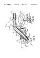
- FIG. 1is an exploded perspective view of one preferred embodiment of the present invention
- FIG. 2is a partial perspective view of one embodiment of a mounting base and outrigger pole holder
- FIG. 3is a cross-sectional view through lines 3--3 of FIG. 2;
- FIG. 4is a cross-sectional view taken through lines 4--4 of FIG. 2;
- FIG. 5is a top plan view of a mounting base of an embodiment of the present invention.
- FIG. 6is a bottom plan view of the mounting base of FIG. 5;
- FIG. 7is a partial enlarged view of the embodiment of FIG. 3 within circle designation 7;
- FIG. 7ais the partial enlarged view of FIG. 7 illustrating the pole holder nut removed from its locking position within the socket;
- FIG. 8is a cross-sectional view of an alternate embodiment of FIG. 3;
- FIG. 9is a top plan view of the embodiment of FIG. 8;
- FIG. 10is a side elevational view of the embodiment of FIG. 3;
- FIG. 11is another embodiment of FIG. 2;
- FIG. 12is a side elevational cut-away view of the embodiment of FIG. 11;
- FIG. 13is a cross-sectional view through lines 13--13 of FIG. 11;
- FIG. 14is a cut-away top plan view of the mounting base of FIG. 11;
- FIG. 15is a bottom plan view of the mounting base of FIG. 11;
- FIG. 16is an exploded cut-away view of one embodiment of an outrigger pole of the present invention.
- FIG. 17is a partial cross-sectional view of tubular sections of an embodiment of the present invention illustrating a retracted arrangement of the tubular sections;
- FIG. 17ais a partial cross-sectional view of the tubular sections illustrating a fully retracted outrigger pole position
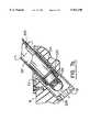
- FIG. 18is a partial cross-sectional view of the tubular sections of FIG. 17 illustrating a fully extended position of the tubular sections;
- FIG. 19is a cross-sectional view through lines 19--19 of FIG. 16.
- FIG. 20is a cross-sectional view through lines 20--20 of FIG. 16.
- a sport fishing boat outrigger apparatus 10for mounting to a boat deck surface such as a gunwale 12 of the boat 14 and for extending fishing lines such as an outrigger rigging line 16 outwardly and outboard 18 from the boat, comprises, by way of example, a mounting base 100 mounted to the gunwale 12, which base engeagably receives an outrigger pole holder 200 for securing an outrigger pole 300.
- the mounting base 100in one preferred embodiment of the present invention, and as illustrated with reference to FIGS. 2 and 3, includes a base plate 110 having an aperture 112 for receiving the pole holder 200 therethrough, and a mounting base sleeve 114 having an open proximal end 116 integrally formed with the base plate for receiving the outrigger pole holder within the sleeve through the base plate aperture.
- the sleeve proximal end 116is integrally formed with the base plate 110 to integrally form the plate to the sleeve proximal end.
- the mounting base 100is an integrally formed cast piece.
- the mounting base 100 and outrigger pole holder 200are formed from stainless steel materials for providing strength, minimum maintenance arid protection against a salt water environment.
- the mounting base 100comprises a hex-nut socket 118 affixed to the sleeve distal end 120 for receiving a hex-nut therein, as will be described later with reference to the outrigger pole holder 200.
- the hex-nut and socket combinationprovides twelve pre-selected rotational positions to choose from when orienting the holder 200 within the mounting base 100. It is appreciated that various styled sockets having a multi faceted bore wall can be used.
- the mounting base 100comprises mounting means for mounting the base plate 110 to the boat gunwale 12 which includes the base plate 110 having mounting holes 122 passing therethrough for receiving mounting screws 124 for securing the mounting base to the boat gunwale.
- the gunwale 12has an opening or hole 20 for receiving the mounting base sleeve 114 therethrough.
- a longitudinal axis 126 of the mounting base sleeve 114forms an acute angle 128 with an imaginary plane including the base plate 110.
- the angle 128comprises approximately a forty five degree angle.
- the outrigger pole holder 200is carried by the mounting base 100 for positioning the outrigger pole 300, earlier described with reference to FIG. 1, therein.
- the outrigger pole holder 200comprises an arcuate tube 210 rotatably journaled within the mounting base sleeve 114.
- the arcuate tube 210comprises an upper end portion 212 extending outward of the sleeve 114 for receiving the outrigger pole 300 therein, and a lower end portion 214 comprising a nut 216 for removably coupling with the mounting base socket 118.
- the arcuate tube 210 of the outrigger pole holder 200comprises an angle bend 218 between the arcuate tube upper end portion 212 and the lower end portion 214 carried within the sleeve 114.
- the angle bend 218comprises approximately a forty five degree angle 220, as illustrated with reference to FIG. 3, formed between the upper axis 222 and lower axis 224 of the arcuate tube end portions 212, 214.
- the angle bend 218comprises approximately a ninety degree angle 226 formed between the axes 222, 224.
- the hex-nut 216comprises a rounded over end portion 228 for guiding the nut into the socket 118 as the outrigger pole holder 200 receivably engages the mounting base 100.
- the rounded over end portion 228provides a smooth sliding of the nut 216 and thus the outrigger pole holder 200 out of and into the mounting base socket 118.
- the rounded over end portion 228eliminates sharp corners or edges that can scratch boat surface finishes.
- the hex-nut 216comprises a spacer sleeve 230 which is welded to the tubular lower end portion 214 of the arcuate tube 210.
- the hex-nut 216is pre-aligned with the socket 118 prior to welding to the arcuate tube lower end portion 214 for providing desirable rotational positions 232, as illustrated again with reference to FIGS. 9 and 10, for directing the outrigger pole holder 200 within the mounting base 100, and thus for directing the outrigger pole 300 into preferred positions when positioned within the holder 200.
- the outrigger pole 300can be positioned generally horizontal and along the boat deck for accommodating the maneuvering of the boat under a low clearance bridge or the like.
- the outrigger pole holder 200is set into the mounting base 100 with the nut 216 engagedly secured within the socket 118 of the mounting base 100.
- the pole holder 200is displaced outwardly from the socket 114 for releasing the nut 216 therefrom, as earlier described and illustrated with reference to FIGS. 7 and 7a.
- the arcuate tube 210is then rotated and repositioned with the nut 216 engaging the socket 118.
- Various pole orientationsare thus achieved as desired by the boater and circumstances with which the boater must content, as herein described by way of example.
- a alternate base sleeve 115will include a length for accommodating various shaped hulls 20.
- alternate mounting means for mounting the base plate 110 to a boat surface such as the gunwale 12will include an adhesive surface 130 depending on the materials used for both the base plate 110 and the gunwale 12, thus eliminating the need for the mounting holes 122.
- the outrigger pole 300is carried in a rotatably engageable manner by the outrigger pole holder 200.
- the outrigger pole 300comprises a plurality of elongated tubular sections 310 of successfully smaller cross-section telescopingly joined to form the outrigger pole 300.
- the outrigger pole 300is movable between a retracted position 312, as illustrated with reference to FIG. 17, and a fully extended position 314, as illustrated with reference to FIG. 18, and again to FIG, 1.
- the outrigger pole 300comprises a spring lock assembly 316 carried within a first end 318 of each elongated tubular section, except the section 310a having the largest cross-section.
- Various embodiments of the present inventionwill include three, four and five tubular sections 310 depending on the particular need of the sport fishing boat, for providing generally eleven, fifteen, and eighteen foot outrigger poles.
- FIG. 1illustrates the outrigger pole 300 having four tubular sections 310a, 310b, 310c, and 310d.
- FIG. 16by way of example illustrates the outrigger pole 300 having three tubular sections 310a, 310b, and 310d.
- the outrigger pole 300comprises, by way of example, a lower tubular section 310a having open ends, an intermediate tubular section 310b having open ends, the intermediate tubular section slidable engaged within the lower tubular section, and an upper tubular section 310d slidably engaged within the intermediate tubular section.
- the upper tubular section 310dincludes a lower open end and an end cap 320 affixed to its uppermost end.
- the tubular sections 310provide for fluid access within the sections through the lower tubular section open end 322 for rinsing internal surfaces therein collecting salt, sand, debris and the like, typically found within the salt water fishing environment.
- the tubular sections 310comprise anodized aluminum for meeting the demands of a salt water environment.
- each elongated tubular section first end 318includes a first hole 324 for receiving a locking detent or button 326 therethrough.
- the spring lock assembly 316includes the locking button 326 biased radially outward through the first hole 324 within the elongated tubular section first end 318.
- Each elongated tubular section 310further includes a second hole 328 positioned within a second end 330 of each elongated tubular section 310, except the section 310d having the smallest cross-section.
- the second hole 328receives the locking button 326 therethrough when the outrigger pole 300 is in the fully extended position 314a stop assembly 332 is carried by the first end 318 of each elongated tubular section 310, except the section 310a having the largest cross-section.
- the stop assembly 332cooperates with the spring lock assembly 316 for limiting the fully extended position 314 such that the second hole 328 within each of the elongated tubular sections 310 is positioned for receiving the locking button 326 therethrough when the outrigger pole 300 is in the fully extended position 314, as again illustrated with reference to FIG. 18.
- the spring lock assembly 316comprises a hair pin styled spring 334.
- the locking button 326is attached to one spring leg 336 and an opposing second spring leg 338 biasingly engages an inside wall portion 340 of the elongated tubular section first end 318, the inside wall portion opposing the first hole 324.
- a bushing styled bung 342is carried within each end 344 of the tubular sections 310 having the spring lock assembly 316, the bung having a bore 346 therethrough for receiving a hinge portion 348 of the hair pin styled spring 334.
- the hair pin styled spring 334is engagable within the bore for limiting outward biasing of the spring legs 336, 338.
- the stop assembly 332in one preferred embodiment, comprises a stop sleeve 350 carried on an outside tubular wall surface of the tubular section first end 318, except the section 310a having the largest cross-section.
- a tubular stop bushing 352is affixed to the tubular section second end 330.
- the stop bushing 352extends into the tubular section second end 330 for engaging the stop sleeve 350 when the outrigger pole 300 is in the fully extended position 314.
- the stop sleeve 350 and stop bushing 352have length dimensions for positioning the locking button 326 for engaging the tubular section second hole 328 for locking the outrigger pole 300 in the fully extended position, as illustrated again with reference to FIG. 18.
- the stop sleeve 350 in the embodiment illustratedhas a hole 351 cooperating with the tubular section first hole 324 for receiving the locking button 326 therethrough.
- the bung 342, sleeve 350, and the bushing 352comprise a non-metallic material for providing ease of telescoping movement and operation of the outrigger pole 300 during movement to and from the retracted 312 and extended 314 positions.
- the tubular section walls, generally of an aluminum material,are therefore making primary contact with non-metallic materials.
- a stop spacer 353is affixed to the inside wall portion 340 just above the spring 334.
- the stop spacer 353engages the bund 342 in a cooperating tubular section, illustrated by way of example in FIG. 17a, wherein the stop spacer 353b engages the bung 342c when the telescoping sections 310b, 310c are in a fully retracted position 313.
- the stop spacer 353protects the spring lock assembly 316 and prevents it from being struck by upper telescoping sections as again illustrated with reference to FIG. 17a.
- the stop spacer 353includes a bore 355 therethrough.
- the stop spacer bore 355, in combination with the bung bore 346 within their respective tubular sections 310, and the pole section open end 322 described with reference to FIG. 16,provide fluid access to inside the tubular sections for flushing out the tubular sections as part of a maintenance procedure as earlier described.
- the outrigger pole 300further comprises a guide ring 354 affixed to the second end 330 of each tubular section 310 carrying the stop bushing 352.
- the guide ring 354secures the stop bushing 352 to the tubular section 310.
- the stop assembly 332thus provides a positively locking method for positioning the outrigger pole 300 in its fully extended position 314 and a defined extension for the pole 300 when extending the line 16 outboard of the boat 14.
- Each eyebolt 358includes a shaft portion 360 for securing the eyebolt to the guide ring 354 and a circular portion for providing an eyelet 362 through which the line 16 is fed for guiding the line outboard of the gunwale 12.
- an uppermost eyebolt 359is secured to the end cap 320.
- the outrigger pole 300includes a pole holder sleeve 364 for providing a precision sliding fit of the outrigger pole 300 into the pole holder 200.
- the sleeve 364is preferably made from a material for providing a non-corroding connection between the pole 300 and holder 200.
Landscapes
- Life Sciences & Earth Sciences (AREA)
- Environmental Sciences (AREA)
- Chemical & Material Sciences (AREA)
- Engineering & Computer Science (AREA)
- Combustion & Propulsion (AREA)
- Mechanical Engineering (AREA)
- Ocean & Marine Engineering (AREA)
- Animal Husbandry (AREA)
- Biodiversity & Conservation Biology (AREA)
- Vehicle Cleaning, Maintenance, Repair, Refitting, And Outriggers (AREA)
Abstract
Description
Claims (53)
Priority Applications (1)
| Application Number | Priority Date | Filing Date | Title |
|---|---|---|---|
| US08/852,222US5921196A (en) | 1997-05-07 | 1997-05-07 | Sport fishing outrigger apparatus |
Applications Claiming Priority (1)
| Application Number | Priority Date | Filing Date | Title |
|---|---|---|---|
| US08/852,222US5921196A (en) | 1997-05-07 | 1997-05-07 | Sport fishing outrigger apparatus |
Publications (1)
| Publication Number | Publication Date |
|---|---|
| US5921196Atrue US5921196A (en) | 1999-07-13 |
Family
ID=25312777
Family Applications (1)
| Application Number | Title | Priority Date | Filing Date |
|---|---|---|---|
| US08/852,222Expired - Fee RelatedUS5921196A (en) | 1997-05-07 | 1997-05-07 | Sport fishing outrigger apparatus |
Country Status (1)
| Country | Link |
|---|---|
| US (1) | US5921196A (en) |
Cited By (29)
| Publication number | Priority date | Publication date | Assignee | Title |
|---|---|---|---|---|
| USD456759S1 (en) | 2000-09-22 | 2002-05-07 | Quality Outdoor Products, Llc | Fishing downrigger assembly |
| US6505431B1 (en) | 2000-09-22 | 2003-01-14 | Quality Outdoor Products, Llc | Tip up downrigger assembly with safety configured and inboard positioned catch pin |
| US6643974B2 (en)* | 2002-03-20 | 2003-11-11 | Windline, Inc. | Pivoting rod holder |
| US6668745B2 (en)* | 2001-07-09 | 2003-12-30 | Taco Metals, Inc. | Outrigger assembly |
| US20040000623A1 (en)* | 2002-04-01 | 2004-01-01 | Slatter Stephen O. | Multi-purpose support plate |
| US20040016385A1 (en)* | 2002-07-15 | 2004-01-29 | Wilcox Roger Scott | Tracking telescoping outrigger |
| US6729065B2 (en)* | 2002-03-05 | 2004-05-04 | Herbert Cooper | Fishing system |
| US6766757B1 (en)* | 2003-10-14 | 2004-07-27 | Richard T. Tilley | Remotely operated outrigger |
| US20040148844A1 (en)* | 2003-01-31 | 2004-08-05 | Edwin Hawn | Carbon fiber outrigger |
| US20050056198A1 (en)* | 2003-09-12 | 2005-03-17 | Slatter Stephen O. | Telescoping outrigger boom with tube locking mechanisms |
| US20050126465A1 (en)* | 2002-07-15 | 2005-06-16 | Wilcox Roger S. | Tracking telescoping outrigger |
| US6928766B1 (en)* | 2002-10-23 | 2005-08-16 | Pipe Welders, Inc. | Automatic outrigger lock |
| US7146763B1 (en)* | 2005-08-15 | 2006-12-12 | Roland Stanton | Fishing pole holder |
| US20070119089A1 (en)* | 2005-11-29 | 2007-05-31 | Reel Wood, Llc | Adjustably mounted side rigger for fishing boat |
| US20070220800A1 (en)* | 2005-11-16 | 2007-09-27 | Laudelino Baez | Manually adjustable outrigger |
| US20080105814A1 (en)* | 2006-10-31 | 2008-05-08 | Slatter Stephen O | Base-plate adapter |
| US20080236021A1 (en)* | 2007-03-27 | 2008-10-02 | Mcnamire Brian L | Cup holder rod and reel mount |
| US20110083356A1 (en)* | 2009-10-13 | 2011-04-14 | Scott Rupp | Telescopic outrigger pole |
| US20110083355A1 (en)* | 2005-11-16 | 2011-04-14 | Wilcox Scott A | Adjustable fishing outrigger apparatus |
| US20110101716A1 (en)* | 2009-10-30 | 2011-05-05 | Matthew Nolte | Utility pole with removable supporting push button |
| US8656632B1 (en)* | 2010-03-18 | 2014-02-25 | Craig Mercier | Outrigger line management system |
| US8683735B1 (en) | 2013-02-28 | 2014-04-01 | Figari Enterprise Inc. | Horizontally opposed universal outrigger assembly |
| US20140137791A1 (en)* | 2012-11-19 | 2014-05-22 | William Alan Bragman | Flush mount rod holder with pad eye |
| US20170071178A1 (en)* | 2015-09-15 | 2017-03-16 | Philip J. Serocki | Rotating Swivel Assemblies for Outriggers |
| US20170086442A1 (en)* | 2015-09-24 | 2017-03-30 | Gem Products, Inc. | Outrigger Clamp |
| US20170089374A1 (en)* | 2015-09-24 | 2017-03-30 | Gem Products, Inc. | Outrigger clamp |
| US20180014522A1 (en)* | 2015-09-24 | 2018-01-18 | Gem Products, Inc. | Outrigger Clamp with Attachment Point |
| US20180139943A1 (en)* | 2016-11-22 | 2018-05-24 | Ledge Logic, LLC | Fishing Dredge Boom |
| US20230406453A1 (en)* | 2020-07-08 | 2023-12-21 | Beatdown Outdoor Products, Llc | Fully telescoping device mount |
Citations (29)
| Publication number | Priority date | Publication date | Assignee | Title |
|---|---|---|---|---|
| US1007322A (en)* | 1910-06-14 | 1911-10-31 | Eastman Kodak Co | Tripod. |
| US1801014A (en)* | 1929-06-29 | 1931-04-14 | Lange Kurt | Tent frame |
| US2229473A (en)* | 1939-03-04 | 1941-01-21 | Norman W Redmer | Tripod |
| US2273791A (en)* | 1940-08-06 | 1942-02-17 | Wirgin Josef | Tripod leg |
| US2427841A (en)* | 1945-03-22 | 1947-09-23 | Film Crafts Engineering Co | Telescopic mast |
| US2517700A (en)* | 1948-09-10 | 1950-08-08 | Eugene A Odin | Telescopic joint |
| US2800737A (en)* | 1955-02-23 | 1957-07-30 | Clifford G Crossan | Landing nets |
| US2921763A (en)* | 1958-01-02 | 1960-01-19 | Worldsbest Ind Inc | Clothes stand |
| US2957187A (en)* | 1958-06-06 | 1960-10-25 | Wilmette Screw Products | Telescopic stand |
| US3063668A (en)* | 1959-12-14 | 1962-11-13 | Lester N Yohe | Outrigger |
| US3103375A (en)* | 1961-04-07 | 1963-09-10 | Earl L Mcmullin | Telescoping pole |
| US3161390A (en)* | 1962-11-14 | 1964-12-15 | Jones Richard L | Outrigger pole bracket for fishing boats |
| US3190594A (en)* | 1963-10-08 | 1965-06-22 | Allan Marine Inc | Outrigger pole holder |
| US3411519A (en)* | 1966-11-18 | 1968-11-19 | Bremshey & Co | Telescopic collapsible umbrella frame |
| US3964706A (en)* | 1974-11-01 | 1976-06-22 | Adams John R | Holder assembly for fishing rods and fishing accessories |
| US3968587A (en)* | 1975-07-21 | 1976-07-13 | Dfk Inc. | Downrigger |
| US3980409A (en)* | 1973-11-14 | 1976-09-14 | Square D Company | Extensible tool for handling energized electric equipment |
| US4004539A (en)* | 1975-09-22 | 1977-01-25 | Wesson Harry J | Marine implement |
| US4621431A (en)* | 1986-04-21 | 1986-11-11 | Mil-Tool, Inc. | Telescoping device with stop mechanism |
| US4836127A (en)* | 1988-06-15 | 1989-06-06 | Wille Mark E | Rod holder adaptor for boat |
| US4993346A (en)* | 1989-08-18 | 1991-02-19 | Rupp Herbert E | Outrigger systems for motorboats |
| US5261434A (en)* | 1993-02-16 | 1993-11-16 | Tech Sport, Inc. | Combination umbrella and golf ball retriever |
| US5301451A (en)* | 1993-10-25 | 1994-04-12 | Vanassche Charles R | Flat line boom |
| US5445102A (en)* | 1992-08-31 | 1995-08-29 | Rupp; Herbert E. | Fishing boat outrigger devices |
| US5458305A (en)* | 1993-05-17 | 1995-10-17 | Woodward; John | Portable intravenous support stand |
| US5519959A (en)* | 1994-08-10 | 1996-05-28 | Cross; Daniel J. | Mounting base for fishing rod holder |
| US5592893A (en)* | 1996-02-14 | 1997-01-14 | E-Tec Marine Products, Inc. | Sport fishing outrigger device |
| US5598598A (en)* | 1993-02-25 | 1997-02-04 | Sorenson; Gregg R. | Paint applicator with improved extensible handle |
| US5778592A (en)* | 1996-03-05 | 1998-07-14 | Malmberg; James A. | Fishing rod tender |
- 1997
- 1997-05-07USUS08/852,222patent/US5921196A/ennot_activeExpired - Fee Related
Patent Citations (29)
| Publication number | Priority date | Publication date | Assignee | Title |
|---|---|---|---|---|
| US1007322A (en)* | 1910-06-14 | 1911-10-31 | Eastman Kodak Co | Tripod. |
| US1801014A (en)* | 1929-06-29 | 1931-04-14 | Lange Kurt | Tent frame |
| US2229473A (en)* | 1939-03-04 | 1941-01-21 | Norman W Redmer | Tripod |
| US2273791A (en)* | 1940-08-06 | 1942-02-17 | Wirgin Josef | Tripod leg |
| US2427841A (en)* | 1945-03-22 | 1947-09-23 | Film Crafts Engineering Co | Telescopic mast |
| US2517700A (en)* | 1948-09-10 | 1950-08-08 | Eugene A Odin | Telescopic joint |
| US2800737A (en)* | 1955-02-23 | 1957-07-30 | Clifford G Crossan | Landing nets |
| US2921763A (en)* | 1958-01-02 | 1960-01-19 | Worldsbest Ind Inc | Clothes stand |
| US2957187A (en)* | 1958-06-06 | 1960-10-25 | Wilmette Screw Products | Telescopic stand |
| US3063668A (en)* | 1959-12-14 | 1962-11-13 | Lester N Yohe | Outrigger |
| US3103375A (en)* | 1961-04-07 | 1963-09-10 | Earl L Mcmullin | Telescoping pole |
| US3161390A (en)* | 1962-11-14 | 1964-12-15 | Jones Richard L | Outrigger pole bracket for fishing boats |
| US3190594A (en)* | 1963-10-08 | 1965-06-22 | Allan Marine Inc | Outrigger pole holder |
| US3411519A (en)* | 1966-11-18 | 1968-11-19 | Bremshey & Co | Telescopic collapsible umbrella frame |
| US3980409A (en)* | 1973-11-14 | 1976-09-14 | Square D Company | Extensible tool for handling energized electric equipment |
| US3964706A (en)* | 1974-11-01 | 1976-06-22 | Adams John R | Holder assembly for fishing rods and fishing accessories |
| US3968587A (en)* | 1975-07-21 | 1976-07-13 | Dfk Inc. | Downrigger |
| US4004539A (en)* | 1975-09-22 | 1977-01-25 | Wesson Harry J | Marine implement |
| US4621431A (en)* | 1986-04-21 | 1986-11-11 | Mil-Tool, Inc. | Telescoping device with stop mechanism |
| US4836127A (en)* | 1988-06-15 | 1989-06-06 | Wille Mark E | Rod holder adaptor for boat |
| US4993346A (en)* | 1989-08-18 | 1991-02-19 | Rupp Herbert E | Outrigger systems for motorboats |
| US5445102A (en)* | 1992-08-31 | 1995-08-29 | Rupp; Herbert E. | Fishing boat outrigger devices |
| US5261434A (en)* | 1993-02-16 | 1993-11-16 | Tech Sport, Inc. | Combination umbrella and golf ball retriever |
| US5598598A (en)* | 1993-02-25 | 1997-02-04 | Sorenson; Gregg R. | Paint applicator with improved extensible handle |
| US5458305A (en)* | 1993-05-17 | 1995-10-17 | Woodward; John | Portable intravenous support stand |
| US5301451A (en)* | 1993-10-25 | 1994-04-12 | Vanassche Charles R | Flat line boom |
| US5519959A (en)* | 1994-08-10 | 1996-05-28 | Cross; Daniel J. | Mounting base for fishing rod holder |
| US5592893A (en)* | 1996-02-14 | 1997-01-14 | E-Tec Marine Products, Inc. | Sport fishing outrigger device |
| US5778592A (en)* | 1996-03-05 | 1998-07-14 | Malmberg; James A. | Fishing rod tender |
Non-Patent Citations (10)
| Title |
|---|
| "Let's Go Boating", 1988, M&E Marine Supply Company, pp. 146 and 147. |
| Boat Show Buyer s Guide , p. 89, Jan. 1996.* |
| Boat Show Buyer s Guide , pp. 85,91, Jan. 1997.* |
| Boat Show Buyer's Guide, p. 89, Jan. 1996. |
| Boat Show Buyer's Guide, pp. 85,91, Jan. 1997. |
| Lee s , pp. 174 175, Jan. 1994.* |
| Lee's, pp. 174-175, Jan. 1994. |
| Let s Go Boating , 1988, M&E Marine Supply Company, pp. 146 and 147.* |
| Overton s , p. 23, Jan. 1992.* |
| Overton's, p. 23, Jan. 1992. |
Cited By (50)
| Publication number | Priority date | Publication date | Assignee | Title |
|---|---|---|---|---|
| US6505431B1 (en) | 2000-09-22 | 2003-01-14 | Quality Outdoor Products, Llc | Tip up downrigger assembly with safety configured and inboard positioned catch pin |
| USD456759S1 (en) | 2000-09-22 | 2002-05-07 | Quality Outdoor Products, Llc | Fishing downrigger assembly |
| US6668745B2 (en)* | 2001-07-09 | 2003-12-30 | Taco Metals, Inc. | Outrigger assembly |
| US6729065B2 (en)* | 2002-03-05 | 2004-05-04 | Herbert Cooper | Fishing system |
| US6643974B2 (en)* | 2002-03-20 | 2003-11-11 | Windline, Inc. | Pivoting rod holder |
| US20050103249A1 (en)* | 2002-04-01 | 2005-05-19 | Taco Metals, Inc. | Multi-purpose support plate |
| US20040000623A1 (en)* | 2002-04-01 | 2004-01-01 | Slatter Stephen O. | Multi-purpose support plate |
| US6851654B2 (en)* | 2002-04-01 | 2005-02-08 | Taco Metals, Inc. | Multi-purpose support plate |
| US7147193B2 (en)* | 2002-04-01 | 2006-12-12 | Slatter Stephen O | Multi-purpose support plate |
| US7025015B2 (en)* | 2002-07-15 | 2006-04-11 | Roger Wilcox | Tracking telescoping outrigger |
| US20040016385A1 (en)* | 2002-07-15 | 2004-01-29 | Wilcox Roger Scott | Tracking telescoping outrigger |
| US20050126465A1 (en)* | 2002-07-15 | 2005-06-16 | Wilcox Roger S. | Tracking telescoping outrigger |
| US6928766B1 (en)* | 2002-10-23 | 2005-08-16 | Pipe Welders, Inc. | Automatic outrigger lock |
| US20040148844A1 (en)* | 2003-01-31 | 2004-08-05 | Edwin Hawn | Carbon fiber outrigger |
| US6889467B2 (en)* | 2003-01-31 | 2005-05-10 | Edwin Hawn | Carbon fiber outrigger |
| US7111574B2 (en)* | 2003-09-12 | 2006-09-26 | Taco Metals, Inc. | Telescoping outrigger boom with tube locking mechanisms |
| US20050056198A1 (en)* | 2003-09-12 | 2005-03-17 | Slatter Stephen O. | Telescoping outrigger boom with tube locking mechanisms |
| US6766757B1 (en)* | 2003-10-14 | 2004-07-27 | Richard T. Tilley | Remotely operated outrigger |
| US7146763B1 (en)* | 2005-08-15 | 2006-12-12 | Roland Stanton | Fishing pole holder |
| US20110083355A1 (en)* | 2005-11-16 | 2011-04-14 | Wilcox Scott A | Adjustable fishing outrigger apparatus |
| US20070220800A1 (en)* | 2005-11-16 | 2007-09-27 | Laudelino Baez | Manually adjustable outrigger |
| US7669361B2 (en)* | 2005-11-16 | 2010-03-02 | Tigress Specialty Metal Products Manufacturing, Inc. | Manually adjustable outrigger |
| US8186095B2 (en)* | 2005-11-16 | 2012-05-29 | Tigress Specialty Metals Products Manufacturing, Inc. | Adjustable fishing outrigger apparatus |
| US20070119089A1 (en)* | 2005-11-29 | 2007-05-31 | Reel Wood, Llc | Adjustably mounted side rigger for fishing boat |
| US20080053361A1 (en)* | 2005-11-29 | 2008-03-06 | Nicholson Paul D | Side rigger for fishing boat |
| US20080105814A1 (en)* | 2006-10-31 | 2008-05-08 | Slatter Stephen O | Base-plate adapter |
| US20080236021A1 (en)* | 2007-03-27 | 2008-10-02 | Mcnamire Brian L | Cup holder rod and reel mount |
| US20110083356A1 (en)* | 2009-10-13 | 2011-04-14 | Scott Rupp | Telescopic outrigger pole |
| US8347546B2 (en)* | 2009-10-13 | 2013-01-08 | Rupp Marine, Inc. | Telescopic outrigger pole |
| US20110101716A1 (en)* | 2009-10-30 | 2011-05-05 | Matthew Nolte | Utility pole with removable supporting push button |
| US9392778B1 (en)* | 2010-03-18 | 2016-07-19 | Craig Mercier | Outrigger line management system |
| US8656632B1 (en)* | 2010-03-18 | 2014-02-25 | Craig Mercier | Outrigger line management system |
| US11589566B1 (en)* | 2010-03-18 | 2023-02-28 | Craig Mercier | Outrigger line management system |
| US9717226B1 (en)* | 2010-03-18 | 2017-08-01 | Craig Mercier | Outrigger line management system |
| US8881668B2 (en)* | 2012-11-19 | 2014-11-11 | William Alan Bragman | Flush mount rod holder with pad eye |
| US20140137791A1 (en)* | 2012-11-19 | 2014-05-22 | William Alan Bragman | Flush mount rod holder with pad eye |
| US8683735B1 (en) | 2013-02-28 | 2014-04-01 | Figari Enterprise Inc. | Horizontally opposed universal outrigger assembly |
| US20170071178A1 (en)* | 2015-09-15 | 2017-03-16 | Philip J. Serocki | Rotating Swivel Assemblies for Outriggers |
| US11766034B2 (en)* | 2015-09-15 | 2023-09-26 | Taco Metals, Llc | Rotating swivel assemblies for outriggers |
| US11116197B2 (en)* | 2015-09-15 | 2021-09-14 | Taco Metals, Llc | Rotating swivel assemblies for outriggers |
| US20220015346A1 (en)* | 2015-09-15 | 2022-01-20 | Taco Metals, Llc | Rotating swivel assemblies for outriggers |
| US20170089374A1 (en)* | 2015-09-24 | 2017-03-30 | Gem Products, Inc. | Outrigger clamp |
| US10470451B2 (en)* | 2015-09-24 | 2019-11-12 | Gem Products, Inc. | Outrigger clamp |
| US10575512B2 (en)* | 2015-09-24 | 2020-03-03 | Gem Products, Inc. | Outrigger clamp with attachment point |
| US10337547B2 (en)* | 2015-09-24 | 2019-07-02 | Gem Products, Inc. | Outrigger clamp |
| US20180014522A1 (en)* | 2015-09-24 | 2018-01-18 | Gem Products, Inc. | Outrigger Clamp with Attachment Point |
| US20170086442A1 (en)* | 2015-09-24 | 2017-03-30 | Gem Products, Inc. | Outrigger Clamp |
| US10561132B2 (en)* | 2016-11-22 | 2020-02-18 | Ledge Logic, LLC | Fishing dredge boom |
| US20180139943A1 (en)* | 2016-11-22 | 2018-05-24 | Ledge Logic, LLC | Fishing Dredge Boom |
| US20230406453A1 (en)* | 2020-07-08 | 2023-12-21 | Beatdown Outdoor Products, Llc | Fully telescoping device mount |
Similar Documents
| Publication | Publication Date | Title |
|---|---|---|
| US5921196A (en) | Sport fishing outrigger apparatus | |
| US20060053677A1 (en) | Fishing rod holder support stanchion member for holding multiple fishing rod holders in combination with a flush mounted rod holder | |
| US4823723A (en) | Trolling rig for fishing boats | |
| US5445102A (en) | Fishing boat outrigger devices | |
| US4551939A (en) | Bass fishing organizer | |
| US4876980A (en) | Fishing rod holder extension | |
| US3063668A (en) | Outrigger | |
| US9173387B2 (en) | Locking twist grip drive handle outrigger positioner | |
| US3802652A (en) | Holder for fishing rod | |
| US8683735B1 (en) | Horizontally opposed universal outrigger assembly | |
| US8468736B2 (en) | Twist grip drive handle outrigger positioner | |
| US3516190A (en) | Fishing rod holder | |
| US8347546B2 (en) | Telescopic outrigger pole | |
| US4641395A (en) | Down rigger boom hinge | |
| US5592893A (en) | Sport fishing outrigger device | |
| US5636467A (en) | Fishing float | |
| US20200093111A1 (en) | Multi-Purpose, Multi-Rod, Modular Fishing System | |
| US4688346A (en) | Butt structure with adjustable reel seat | |
| US4156320A (en) | Downrigger | |
| US4138793A (en) | Fishing float | |
| US3977118A (en) | Fishing rod holder with down rigger attachments | |
| US6484433B1 (en) | Portable fishing rod holder | |
| US5546693A (en) | Hinged fishing rod holder | |
| US20050172534A1 (en) | Articulating trolling rod holder assembly | |
| US6557481B1 (en) | Combined outrigger and fishing rod holder |
Legal Events
| Date | Code | Title | Description |
|---|---|---|---|
| AS | Assignment | Owner name:SLATTER, DONNA J., FLORIDA Free format text:ASSIGNMENT OF ASSIGNORS INTEREST;ASSIGNOR:SLATTER, STEPHEN O.;REEL/FRAME:009000/0833 Effective date:19971208 Owner name:SLATTER, STEPHEN O., FLORIDA Free format text:ASSIGNMENT OF ASSIGNORS INTEREST;ASSIGNOR:SLATTER, STEPHEN O.;REEL/FRAME:009000/0833 Effective date:19971208 | |
| AS | Assignment | Owner name:TACO METALS, INC., A CORP. OF FLORIDA, FLORIDA Free format text:ASSIGNMENT OF ASSIGNORS INTEREST;ASSIGNORS:SLATTER, STEPHEN O.;SLATTER, DONNA J.;REEL/FRAME:010655/0360 Effective date:20000218 | |
| FEPP | Fee payment procedure | Free format text:PAYOR NUMBER ASSIGNED (ORIGINAL EVENT CODE: ASPN); ENTITY STATUS OF PATENT OWNER: SMALL ENTITY | |
| FPAY | Fee payment | Year of fee payment:4 | |
| REMI | Maintenance fee reminder mailed | ||
| FPAY | Fee payment | Year of fee payment:8 | |
| SULP | Surcharge for late payment | Year of fee payment:7 | |
| REMI | Maintenance fee reminder mailed | ||
| LAPS | Lapse for failure to pay maintenance fees | ||
| STCH | Information on status: patent discontinuation | Free format text:PATENT EXPIRED DUE TO NONPAYMENT OF MAINTENANCE FEES UNDER 37 CFR 1.362 | |
| FP | Lapsed due to failure to pay maintenance fee | Effective date:20110713 |