US5920475A - Circuit and method for controlling a synchronous rectifier converter - Google Patents
Circuit and method for controlling a synchronous rectifier converterDownload PDFInfo
- Publication number
- US5920475A US5920475AUS08/696,674US69667496AUS5920475AUS 5920475 AUS5920475 AUS 5920475AUS 69667496 AUS69667496 AUS 69667496AUS 5920475 AUS5920475 AUS 5920475A
- Authority
- US
- United States
- Prior art keywords
- power supply
- switching circuitry
- synchronous rectifier
- power
- recited
- Prior art date
- Legal status (The legal status is an assumption and is not a legal conclusion. Google has not performed a legal analysis and makes no representation as to the accuracy of the status listed.)
- Expired - Lifetime
Links
- 238000000034methodMethods0.000titleclaimsabstractdescription28
- 230000001360synchronised effectEffects0.000titleclaimsdescription123
- 230000002441reversible effectEffects0.000claimsabstractdescription66
- 238000004804windingMethods0.000claimsdescription22
- 230000007704transitionEffects0.000claimsdescription13
- 238000001514detection methodMethods0.000claimsdescription10
- 230000005669field effectEffects0.000claimsdescription6
- 230000000694effectsEffects0.000claimsdescription5
- 229910044991metal oxideInorganic materials0.000claimsdescription5
- 150000004706metal oxidesChemical class0.000claimsdescription5
- 239000004065semiconductorSubstances0.000claimsdescription5
- 238000010168coupling processMethods0.000claims12
- 238000005859coupling reactionMethods0.000claims12
- 230000008878couplingEffects0.000claims9
- 230000003247decreasing effectEffects0.000claims1
- 230000002457bidirectional effectEffects0.000abstractdescription24
- 238000010586diagramMethods0.000description17
- 239000008186active pharmaceutical agentSubstances0.000description7
- 230000008901benefitEffects0.000description5
- 230000001052transient effectEffects0.000description4
- 230000001627detrimental effectEffects0.000description3
- 230000008030eliminationEffects0.000description3
- 238000003379elimination reactionMethods0.000description3
- UXUFTKZYJYGMGO-CMCWBKRRSA-N(2s,3s,4r,5r)-5-[6-amino-2-[2-[4-[3-(2-aminoethylamino)-3-oxopropyl]phenyl]ethylamino]purin-9-yl]-n-ethyl-3,4-dihydroxyoxolane-2-carboxamideChemical compoundO[C@@H]1[C@H](O)[C@@H](C(=O)NCC)O[C@H]1N1C2=NC(NCCC=3C=CC(CCC(=O)NCCN)=CC=3)=NC(N)=C2N=C1UXUFTKZYJYGMGO-CMCWBKRRSA-N0.000description2
- 238000005259measurementMethods0.000description2
- 230000008569processEffects0.000description2
- 230000005355Hall effectEffects0.000description1
- 230000009471actionEffects0.000description1
- 230000003213activating effectEffects0.000description1
- 230000004075alterationEffects0.000description1
- 230000009286beneficial effectEffects0.000description1
- 239000003990capacitorSubstances0.000description1
- 230000008859changeEffects0.000description1
- 238000006243chemical reactionMethods0.000description1
- 238000010276constructionMethods0.000description1
- 230000005611electricityEffects0.000description1
- 238000005516engineering processMethods0.000description1
- 210000003754fetusAnatomy0.000description1
- 230000000977initiatory effectEffects0.000description1
- 238000004519manufacturing processMethods0.000description1
- 238000011084recoveryMethods0.000description1
- 230000004044responseEffects0.000description1
- 230000003068static effectEffects0.000description1
- 238000006467substitution reactionMethods0.000description1
- 230000001960triggered effectEffects0.000description1
Images


Classifications
- H—ELECTRICITY
- H02—GENERATION; CONVERSION OR DISTRIBUTION OF ELECTRIC POWER
- H02M—APPARATUS FOR CONVERSION BETWEEN AC AND AC, BETWEEN AC AND DC, OR BETWEEN DC AND DC, AND FOR USE WITH MAINS OR SIMILAR POWER SUPPLY SYSTEMS; CONVERSION OF DC OR AC INPUT POWER INTO SURGE OUTPUT POWER; CONTROL OR REGULATION THEREOF
- H02M3/00—Conversion of DC power input into DC power output
- H02M3/02—Conversion of DC power input into DC power output without intermediate conversion into AC
- H02M3/04—Conversion of DC power input into DC power output without intermediate conversion into AC by static converters
- H02M3/10—Conversion of DC power input into DC power output without intermediate conversion into AC by static converters using discharge tubes with control electrode or semiconductor devices with control electrode
- H02M3/145—Conversion of DC power input into DC power output without intermediate conversion into AC by static converters using discharge tubes with control electrode or semiconductor devices with control electrode using devices of a triode or transistor type requiring continuous application of a control signal
- H02M3/155—Conversion of DC power input into DC power output without intermediate conversion into AC by static converters using discharge tubes with control electrode or semiconductor devices with control electrode using devices of a triode or transistor type requiring continuous application of a control signal using semiconductor devices only
- H02M3/156—Conversion of DC power input into DC power output without intermediate conversion into AC by static converters using discharge tubes with control electrode or semiconductor devices with control electrode using devices of a triode or transistor type requiring continuous application of a control signal using semiconductor devices only with automatic control of output voltage or current, e.g. switching regulators
- H02M3/1563—Conversion of DC power input into DC power output without intermediate conversion into AC by static converters using discharge tubes with control electrode or semiconductor devices with control electrode using devices of a triode or transistor type requiring continuous application of a control signal using semiconductor devices only with automatic control of output voltage or current, e.g. switching regulators without using an external clock
- H—ELECTRICITY
- H02—GENERATION; CONVERSION OR DISTRIBUTION OF ELECTRIC POWER
- H02J—CIRCUIT ARRANGEMENTS OR SYSTEMS FOR SUPPLYING OR DISTRIBUTING ELECTRIC POWER; SYSTEMS FOR STORING ELECTRIC ENERGY
- H02J1/00—Circuit arrangements for DC mains or DC distribution networks
- H02J1/001—Hot plugging or unplugging of load or power modules to or from power distribution networks
- H—ELECTRICITY
- H02—GENERATION; CONVERSION OR DISTRIBUTION OF ELECTRIC POWER
- H02J—CIRCUIT ARRANGEMENTS OR SYSTEMS FOR SUPPLYING OR DISTRIBUTING ELECTRIC POWER; SYSTEMS FOR STORING ELECTRIC ENERGY
- H02J1/00—Circuit arrangements for DC mains or DC distribution networks
- H02J1/10—Parallel operation of DC sources
- H02J1/102—Parallel operation of DC sources being switching converters
- H—ELECTRICITY
- H02—GENERATION; CONVERSION OR DISTRIBUTION OF ELECTRIC POWER
- H02M—APPARATUS FOR CONVERSION BETWEEN AC AND AC, BETWEEN AC AND DC, OR BETWEEN DC AND DC, AND FOR USE WITH MAINS OR SIMILAR POWER SUPPLY SYSTEMS; CONVERSION OF DC OR AC INPUT POWER INTO SURGE OUTPUT POWER; CONTROL OR REGULATION THEREOF
- H02M3/00—Conversion of DC power input into DC power output
- H02M3/22—Conversion of DC power input into DC power output with intermediate conversion into AC
- H02M3/24—Conversion of DC power input into DC power output with intermediate conversion into AC by static converters
- H02M3/28—Conversion of DC power input into DC power output with intermediate conversion into AC by static converters using discharge tubes with control electrode or semiconductor devices with control electrode to produce the intermediate AC
- H02M3/325—Conversion of DC power input into DC power output with intermediate conversion into AC by static converters using discharge tubes with control electrode or semiconductor devices with control electrode to produce the intermediate AC using devices of a triode or a transistor type requiring continuous application of a control signal
- H02M3/335—Conversion of DC power input into DC power output with intermediate conversion into AC by static converters using discharge tubes with control electrode or semiconductor devices with control electrode to produce the intermediate AC using devices of a triode or a transistor type requiring continuous application of a control signal using semiconductor devices only
- H02M3/33569—Conversion of DC power input into DC power output with intermediate conversion into AC by static converters using discharge tubes with control electrode or semiconductor devices with control electrode to produce the intermediate AC using devices of a triode or a transistor type requiring continuous application of a control signal using semiconductor devices only having several active switching elements
- H02M3/33576—Conversion of DC power input into DC power output with intermediate conversion into AC by static converters using discharge tubes with control electrode or semiconductor devices with control electrode to produce the intermediate AC using devices of a triode or a transistor type requiring continuous application of a control signal using semiconductor devices only having several active switching elements having at least one active switching element at the secondary side of an isolation transformer
- H02M3/33584—Bidirectional converters
- H—ELECTRICITY
- H02—GENERATION; CONVERSION OR DISTRIBUTION OF ELECTRIC POWER
- H02M—APPARATUS FOR CONVERSION BETWEEN AC AND AC, BETWEEN AC AND DC, OR BETWEEN DC AND DC, AND FOR USE WITH MAINS OR SIMILAR POWER SUPPLY SYSTEMS; CONVERSION OF DC OR AC INPUT POWER INTO SURGE OUTPUT POWER; CONTROL OR REGULATION THEREOF
- H02M3/00—Conversion of DC power input into DC power output
- H02M3/22—Conversion of DC power input into DC power output with intermediate conversion into AC
- H02M3/24—Conversion of DC power input into DC power output with intermediate conversion into AC by static converters
- H02M3/28—Conversion of DC power input into DC power output with intermediate conversion into AC by static converters using discharge tubes with control electrode or semiconductor devices with control electrode to produce the intermediate AC
- H02M3/325—Conversion of DC power input into DC power output with intermediate conversion into AC by static converters using discharge tubes with control electrode or semiconductor devices with control electrode to produce the intermediate AC using devices of a triode or a transistor type requiring continuous application of a control signal
- H02M3/335—Conversion of DC power input into DC power output with intermediate conversion into AC by static converters using discharge tubes with control electrode or semiconductor devices with control electrode to produce the intermediate AC using devices of a triode or a transistor type requiring continuous application of a control signal using semiconductor devices only
- H02M3/33569—Conversion of DC power input into DC power output with intermediate conversion into AC by static converters using discharge tubes with control electrode or semiconductor devices with control electrode to produce the intermediate AC using devices of a triode or a transistor type requiring continuous application of a control signal using semiconductor devices only having several active switching elements
- H02M3/33576—Conversion of DC power input into DC power output with intermediate conversion into AC by static converters using discharge tubes with control electrode or semiconductor devices with control electrode to produce the intermediate AC using devices of a triode or a transistor type requiring continuous application of a control signal using semiconductor devices only having several active switching elements having at least one active switching element at the secondary side of an isolation transformer
- H02M3/33592—Conversion of DC power input into DC power output with intermediate conversion into AC by static converters using discharge tubes with control electrode or semiconductor devices with control electrode to produce the intermediate AC using devices of a triode or a transistor type requiring continuous application of a control signal using semiconductor devices only having several active switching elements having at least one active switching element at the secondary side of an isolation transformer having a synchronous rectifier circuit or a synchronous freewheeling circuit at the secondary side of an isolation transformer
- Y—GENERAL TAGGING OF NEW TECHNOLOGICAL DEVELOPMENTS; GENERAL TAGGING OF CROSS-SECTIONAL TECHNOLOGIES SPANNING OVER SEVERAL SECTIONS OF THE IPC; TECHNICAL SUBJECTS COVERED BY FORMER USPC CROSS-REFERENCE ART COLLECTIONS [XRACs] AND DIGESTS
- Y02—TECHNOLOGIES OR APPLICATIONS FOR MITIGATION OR ADAPTATION AGAINST CLIMATE CHANGE
- Y02B—CLIMATE CHANGE MITIGATION TECHNOLOGIES RELATED TO BUILDINGS, e.g. HOUSING, HOUSE APPLIANCES OR RELATED END-USER APPLICATIONS
- Y02B70/00—Technologies for an efficient end-user side electric power management and consumption
- Y02B70/10—Technologies improving the efficiency by using switched-mode power supplies [SMPS], i.e. efficient power electronics conversion e.g. power factor correction or reduction of losses in power supplies or efficient standby modes
Definitions
- the present inventionis directed, in general, to power systems and, more particularly, to a control circuit for operating a power rectifier in both a bidirectional and unidirectional mode of operation as a function of a characteristic of the power system.
- Increased power densityis a continuing goal of modern power supply design.
- High power densityis particularly crucial in applications wherein the allocated space for the power supply relative to the power output is restricted.
- the power supplyIn addition to being highly compact, the power supply must also be efficient to limit heat-creating power dissipation.
- Illustrative applications for a high density power supplyinclude an off-line power supply used to power a laptop computer or a power supply module for a telecommunication system employing an Integrated Services Digital Network ("ISDN").
- ISDNIntegrated Services Digital Network
- Bridge-type convertersare particularly suitable for such applications, since they may be designed to operate resonantly. Resonance is an operational mode that permits both high power density and efficiency.
- One example of a bridge-type converteris a half-bridge converter as disclosed in U.S. Pat. No. 5,274,543 to Loftus, issued on Dec. 28, 1993, entitled “Zero-Voltage Switching Power Converter with Lossless Synchronous Rectifier Gate Drive” and incorporated herein by reference.
- Loftus' converteroperates as a forward converter and includes a bridge circuit comprising two power switching transistors to drive a primary transformer.
- Loftusdiscloses a drive arrangement and operative scheme for driving the power transistors, thereby limiting the dissipation losses within the power switching transistors.
- the drive circuitrydrives the power switching transistors with unequal duty cycles having a conducting duration such that the sum of the conduction intervals substantially equals the combined switching period of the power transistors.
- the conducting intervalsare separated by very short dead time intervals controlled by the differing turn-on and turn-off times of the power switching transistor.
- the short interval between alternate conductions of the power switching transistorsis sufficient in duration to allow zero voltage turn-on of the power switching transistors but short enough in duration to minimize power loss and conducted noise.
- MOSFETmetal oxide semiconductor field effect transistor
- the normal operating mode for converters operating with forced load-sharingis for each converter to provide an equal portion of the total load current.
- a control terminal of the convertersare coupled together in a star connection, thereby providing the necessary feedback to equalize the load currents actively.
- Bidirectional current flowcan provide some significant advantages, perhaps the most common of which is elimination of the so-called critical current phenomenon found in buck-derived converters.
- the bidirectional current flow characteristicallows inductor current in the synchronous rectifier circuit to flow continuously, thereby avoiding a sluggish reaction to a load or transient on the output of the converter circuit.
- this bi-directional power flow characteristiccan result in an undesirable (and possibly damaging) operating mode wherein one converter drives the output of another.
- the overall power systemcan be circulating large amounts of current while actually delivering very little current to the load. This results in high power dissipation during lighter load conditions.
- the system transient responsecould be detrimentally affected as the converters transition from the reverse power processing mode to a forward power processing mode.
- Parallel (forced load-sharing) circuitry in each converter, responsible for driving the rectifier devices,may not be able to prevent this mode of operation, as the parallel circuit is specifically designed to be effective over a limited range. See U.S. Pat. No. 5,036,452 to Loftus, issued on Jul. 30, 1991, entitled “Current Sharing Control with Limited Output Voltage Range for Paralleled Power Converters,” and incorporated herein by reference, for a discussion of load sharing between power circuits connected in parallel to a common load. Therefore, it is beneficial to provide a circuit that prevents reverse power flow in converters configured for parallel operation.
- a resonant reset forward converter with a novel synchronous rectifier drive circuitcomprises a pair of switches to disable the gate drive of one synchronous field effect transistor ("FET") based on switch current.
- FETsynchronous field effect transistor
- Another synchronous FETuses an output inductor to generate the drive voltage, and can be configured off when the inductor current goes discontinuous. The idea is to detect when the converter goes into discontinuous conduction mode, and to use this information to disable the synchronous rectifiers, thus preventing a catastrophic failure.
- the described circuitwhich is designed for parallel operation, uses droop regulation to achieve load sharing, rather than active load sharing using a parallel pin connection.
- the circuitthus, turns one of the FETs off based on switch current, and the other FET off based on a discontinuous current condition.
- the circuit as describedis only compatible with a self-synchronized drive scheme. Moreover, the circuit as described apparently only has a problem when a converter falls below critical inductor current. Both the transformer secondary voltage and the inductor voltage can collapse to zero during discontinuous conduction mode. The output voltage supplied by the paralleled modules could then energize the gates of the synchronous FETs, thus turning them on at the wrong time. Stated another way, the resonant reset topology forces a finite dead time in the gate drive of one synchronous FET, allowing the critical current point to occur. Finally, the circuit as described is limited to a passive droop sharing method, and does not accomplish active load sharing with a feedback sensing current circuit.
- control circuitfor operating a power rectifier, the control circuit capable of sensing conditions under which reverse power flow may occur in the rectifier and taking steps to prevent the reverse power flow.
- U.S. patent application Ser. No. 08/434,712is directed toward a control circuit for operating a power rectifier in both a bidirectional and unidirectional mode of operation as a function of an output level of the rectifier.
- the control circuitryis capable of sensing an output level of the rectifier and transitioning switching circuitry between the bidirectional mode and the unidirectional mode as a function of the output current level to prevent substantial reverse power flow through the rectifier.
- U.S. patent application Ser. No. 08/434,712introduces a bi-modal converter having both a bidirectional and unidirectional mode of operation.
- the output level of the convertermay be determined by measuring voltage, current, power or another suitable characteristic.
- the rectifieris particularly useful in power systems having a plurality of rectifiers operating in parallel to prevent one rectifier from driving the other.
- the present inventionprovides a control circuit for operating a power rectifier in both a bidirectional and unidirectional mode of operation, but as a function of a characteristic of the power system employing the rectifier as opposed to an output level of the rectifier.
- the present inventionprovides, for use in a power system having a power train, a rectifier having an input and an output and a method of controlling the rectifier.
- the rectifierincludes: (1) switching circuitry coupled between the input and the output, the switching circuitry adapted to operate in selected one of (a) a bidirectional mode of operation and (b) an unidirectional mode of operation to rectify substantially alternating current at the input to produce substantially direct current at the output; and (2) control circuitry coupled to a control input of the switching circuitry, the control circuitry capable of sensing a characteristic of the power system and transitioning the switching circuitry between the bidirectional mode and the unidirectional mode as a function of the characteristic thereby to prevent substantial reverse power flow through the rectifier.
- the present inventiontherefore, also introduces a bi-modal converter having two modes of operation.
- the switching circuitryswitches to rectify the substantially alternating current, perhaps in resonance to realize the efficiencies of a resonant converter. Bidirectional current flow is possible in this mode of operation.
- the switching circuitryacts as a diode rectifier, allowing only unidirectional current and thereby preventing reverse power flow.
- the control circuitryswitches between the bidirectional and unidirectional modes of operation as a function of characteristics of the power system employing the rectifier.
- the characteristicsinclude, without limitation, a signal indicative of an output level of the rectifier, an intermediate control signal of the power system, an error signal of the power system, a duty ratio of a switch associated with the power train of the power system and a period of time associated with an operation of the power system.
- the rectifieris particularly useful in power systems having a plurality of rectifiers operating in parallel to prevent one rectifier from driving the other.
- the switching circuitrycomprises MOSFET switches.
- switches having a low R DS (on)are suitable for use with the present invention.
- any switching devicee.g., GaAsFET is well within the broad scope of the present invention.
- the switching circuitrycomprises a plurality of switches, the control circuitry capable of transitioning the switching circuitry between the bidirectional mode and the unidirectional mode by disabling all of the plurality of switches.
- the rectifiertransitions to the unidirectional mode of operation by disabling all of the plurality of switches associated with the switching circuitry.
- the rectifieralso transitions to the unidirectional mode of operation by disabling at least one of the plurality of switches associated with the switching circuitry.
- the rectifieris coupled in parallel with a second rectifier, the control circuitry substantially preventing the second rectifier from causing the substantial reverse power flow.
- the present inventionis operable in a power system comprising multiple rectifiers.
- the switching circuitrycomprises discrete diodes to allow the switching circuitry to operate in the unidirectional mode.
- the diodesconduct electricity when the control circuitry deactivates the switches.
- the present inventionmay employ body diodes integral with MOSFET switches.
- the rectifierfurther comprises a self-synchronized drive circuit adapted to provide a drive signal to the switching circuitry for varying a duty cycle of the switching circuitry as a function of the characteristic of the power system (closed loop).
- the rectifiermay be controlled without regard to actual characteristic of the power system (open loop).
- an active load-sharing circuitis coupled to the rectifier and a second rectifier to effect load sharing therebetween.
- the control circuitryis enabled only when the rectifier is coupled in parallel with the second rectifier.
- the control circuittransitions the switching circuitry from the bidirectional mode to the unidirectional mode when the characteristic of the power system drops below a predetermined threshold level. For instance, the control circuitry transitions the switching circuitry between the bidirectional mode and the unidirectional mode when a signal indicative of an output current of the rectifier is between about 5% and about 10% of a full rated output current level.
- FIG. 1illustrates a schematic diagram of a plurality of converters operating in a parallel forced load-sharing converter circuit
- FIG. 2illustrates a schematic diagram of a plurality of converters operating in a parallel forced load-sharing converter circuit with one converter processing power in a reverse direction;
- FIG. 3illustrates a schematic diagram of a clamped-mode forward converter circuit with a synchronous rectifier circuit in accordance with U.S. patent application Ser. No. 08/343,712;
- FIG. 4illustrates a schematic diagram of a non-isolated buck converter with a diode rectifier
- FIG. 5illustrates a schematic diagram of a non-isolated buck converter with a synchronous rectifier circuit employing the principles of the present invention
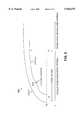
- FIG. 6illustrates a graphical representation of an average and instantaneous inductor current of the non-isolated buck converter of FIG. 5;
- FIG. 7illustrates a timing diagram of a start-up sequence for a plurality of converters operating in a parallel forced load-sharing converter circuit
- FIG. 8illustrates a schematic diagram of the converter of FIG. 5 employed in a system employing a plurality of converters.
- FIG. 9illustrates a timing diagram of a start-up sequence for the system of FIG. 8.
- FIG. 1is a schematic diagram of a plurality of converters operating in a parallel forced load-sharing converter circuit 100.
- the circuit 100comprises a first DC/DC converter 110, a second DC/DC converter 120 and a third DC/DC converter 130 configured for parallel operation.
- the DC/DC converters 110, 120, 130function by converting a DC input voltage V in to alternating current ("AC") and converting the AC back into a DC output voltage V out .
- the DC input voltage V inis applied across the input of the circuit 100 and an input current, I in1 , I in2 , I in3 enters the DC/DC converters 110, 120, 130, respectively.
- an output current, I out1 , I out2 , I out3exits each DC/DC converter 110, 120, 130, respectively.
- a combined load current, I load and the DC output voltage V outare delivered across an output resistive load 195.
- the normal operating mode for converters operating with forced load-sharingis for each converter to provide an equal proportion of the load current.
- the parallel pins of the convertersare connected together in a star connection, which provides the necessary feedback to actively equalize the load currents.
- FIG. 2illustrated is a schematic diagram of a plurality of converters operating in a parallel forced load-sharing converter circuit 200 with one converter processing power in a reverse direction.
- the circuit 200comprises a first DC/DC converter 210, a second DC/DC converter 220 and a third DC/DC converter 230 configured for parallel operation.
- a voltage V inis applied across the input of the circuit 200 and an input current I in1 , I in2 enters the first and second DC/DC converters 210, 220, respectively.
- an input current I in3is illustrated exiting the third DC/DC converter 230.
- An output current I out1 , I out2is illustrated exiting the first and second DC/DC converters 210, 220, respectively, but an output current I out3 enters the third DC/DC converter 230 in a reverse direction.
- a combined load current I load and output voltage V outis delivered across an output resistive load 295.
- the first and second DC/DC converters 210, 220are processing power in a normal, forward direction, while the third DC/DC converter 230 is processing power in the reverse direction.
- the overall power systemcould be circulating large amounts of current while delivering very little current to the load. This results in a high power dissipation during lighter load conditions.
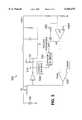
- FIG. 3illustrated is a schematic diagram of a clamped-mode forward converter circuit 300 with a synchronous rectifier circuit 330 in accordance with U.S. patent application Ser. No. 08/343,712.
- the clamped-mode forward converter circuit 300 and its advantagesare discussed in U.S. Pat. No. 5,303,138 to Rozman, issued on Apr. 12, 1994, entitled “Low Loss Synchronous Rectifier for Application to Clamped-Mode Power Converters" and incorporated herein by reference.
- the clamped-mode forward converter circuit 300comprises a voltage input V in connected to a primary winding 310 of a power transformer by a power switch (e.g., MOSFET) Q1.
- MOSFETpower switch
- the power switch Q1is shunted by series connection of a clamp capacitor Cclamp and a power switch Q2.
- the conducting intervals of the power switch Q1 and the power switch Q2are mutually exclusive.
- the duty cycle of the power switch Q1is D and the duty cycle of the power switch Q2 is 1-D.
- a secondary winding 335 of the power transformeris connected to an output capacitance load C out through an output filter inductor L out and the synchronous rectifier circuit 330, providing a substantially alternating current input to the synchronous rectifier circuit 330.
- the synchronous rectifier circuit 330comprises control circuitry 350 and switching circuitry.
- a synchronous rectifier device SR1 and a synchronous rectifier device SR2comprise the switching circuitry.
- the switching circuitrymay be realized with any suitable rectifier devices, although a low R DS (on) N-channel MOSFET is suitable for such applications.
- a diode D1 and a diode D2are discrete devices placed in parallel with the synchronous rectifier devices SR1, SR2, respectively. However, the diodes D1, D2 may represent an integral body diode of a N-channel MOSFET.
- the synchronous rectifier control circuit 350may be either a control driven circuit, or a self-synchronized drive circuit. Additionally, the overall power train topology encompasses any topology suitable for synchronous rectification, and is not limited to the topology shown in the illustrated embodiment.
- the present inventionalso comprises a current sensing device 365 capable of sensing a converter output level.
- the current sensing device 365encompasses a current transformer connected in series with the power switch Q1, a shunt resistor in series with the output, or a Hall effect current sense device in series with the output. The sensed current signal is then provided to a parallel control circuitry 370 to facilitate forced load-sharing.
- the current signalis also provided to a level detector 375 which compares the load current to some predetermined reference level.
- the detector 375will disable the synchronous rectifier drive circuit 330. This action reconfigures the converter from a synchronous rectifier circuit to a conventional diode rectifier circuit. Since a diode rectifier circuit cannot process power in the reverse direction, the proposed circuit effectively prevents reverse power flow.
- the synchronous rectifier drive circuit 330is enabled, resuming normal operation.
- the control circuit 350transitions the switching circuitry SR1, SR2 from the bidirectional mode to the unidirectional mode when the output current level drops below a predetermined threshold level.
- the circuitretains the efficiency benefits of synchronous rectification at higher loads, where efficiency is most important. Reconfiguring the circuit to diode rectification at light loads prevents reverse power flow, but should not significantly impact light load efficiency. In fact, light load efficiency may be improved with diode rectification, as the overhead of the MOSFET gate drive loss (associated with the switching circuitry) is eliminated.
- the remaining circuitryis standard for synchronous rectifier circuits configured for parallel operation.
- a voltage regulator 380monitors the load and restores the output voltage V out to within tolerance limits despite changes in both the load and the input voltage V in .
- a pulse-width modulation (“PWM”) circuit 385is included to keep the output voltage V out of the converter constant over the various operating conditions.
- the circuitsare coupled as illustrated by the interconnecting lines and arrows, and the synchronous rectifier control circuitry 350 and the PWM circuit 385 are coupled to the clamped-mode circuit 300.
- the load current level detector circuit 375may be disabled during non-paralleled, or stand alone, operation. An additional circuit may then be incorporated into the design that senses parallel operation (e.g. ground the parallel pin when not in use) and disable the load current level detector circuit 375 during non-parallel operation.
- the synchronous rectifier circuit 330also transitions to the unidirectional mode of operation by disabling at least one of the synchronous rectifier devices SR1 or SR2. Therefore, by disabling synchronous rectifier device SR1, for instance, reverse power flow will be prevented in the synchronous rectifier drive circuit 330.
- FIG. 4illustrated is a schematic diagram of a non-isolated buck converter 400 with a diode rectifier D1.
- the non-isolated buck converter 400includes a power switch Q1 analogous to the power switch Ql presented in FIG. 3.
- the non-isolated buck converter 400also includes a capacitance load C o through a filter inductor L o and a resistive load R o .
- the non-isolated buck converter 400further includes a voltage regulator 450 to monitor the load and restore an output voltage V out to within tolerance limits despite changes in both the load and an input voltage V in .
- the non-isolated buck converter 400still further includes a PWM circuit 470 to keep the output voltage V out of the converter 400 constant over the various operating conditions.
- the non-isolated buck converter 400employing a single diode rectifier D1 to provide a rectified output voltage V out , does not endure reverse power flow conditions. However, a significant increase in power converter efficiency can be achieved by replacing the rectifier diode D1 with a synchronous rectifier circuit as described with respect to FIG. 5.
- FIG. 5illustrated is a schematic diagram of a non-isolated buck converter (“buck converter”) 500 with a synchronous rectifier circuit 510 employing the principles of the present invention.
- the buck converter 500includes a power switch Q1, capacitance load C o , filter inductor L o , resistive load R o , voltage regulator 550 and PWM circuit 570.
- the synchronous rectifier circuit 510includes control circuitry 520 and switching circuitry.
- a switch (e.g., MOSFET) Q2comprises the switching circuitry.
- the switching circuitrymay be realized with any suitable rectifier devices including a low R DS (on) N-channel MOSFET with an integral body diode of the N-channel MOSFET.
- the switch Q2is capable of carrying bidirectional current and the buck converter 500 is susceptible to bidirectional power flow.
- the switch Q2may be disabled through the control circuitry 520 coupled to a sensing device 530. Analogous to rectifier circuit of FIG. 3, the rectifier transitions from the bidirectional mode to the unidirectional mode of operation by disabling switch Q2 (analogous to disabling synchronous rectifier device SR1 in FIG. 3).
- the bidirectional power flowis prevented in the buck converter 500 by replacing the switch Q2 with a diode or by disabling the switch Q2 and relying on its integral body diode.
- the control circuitry 520may be either a control driven circuit, or a self-synchronized drive circuit. Additionally, the overall power train topology encompasses any topology suitable for synchronous rectification including, without limitation, transformer isolated topologies, and is not limited to the topology shown in the illustrated embodiment.
- Instantaneous reverse power (or inductor current) flowmay be defined as negative power (or current) flow for only a portion of each switching cycle. The current does not remain negative for an entire switching cycle.
- Average reverse power (or inductor current) flowmay be defined as a net negative current averaged over more than one switching cycle. During a start-up or shut-down transient, for example, average negative current could be maintained for several switching cycles prior to the current settling out in steady state, but need not remain negative continuously.
- Waveform 1 of the graphical representation 600illustrates a condition where an average inductor current I ave1 and instantaneous inductor current I Lout1 are positive. This circumstance represents a normal operating condition for the buck converter 500 (e.g, full load).
- waveform 2illustrated is a condition where the average inductor current I ave2 is positive, but the instantaneous inductor current I Lout2 is negative for a portion of each switching cycle.
- the instantaneous inductor current I Lout2it is often desirable to allow the instantaneous inductor current I Lout2 to flow as it prevents discontinuous inductor current and the associated detrimental effects on the control loop. It is not detrimental to the operation of two or more units in parallel to allow instantaneous negative inductor current I Lout2 for a portion of each cycle. It is important, however, to prevent large values of negative average current I ave2, as this may cause excessive power dissipation, a glitch on the bus voltage or other performance problems.
- a relatively small amount of negative average current flow I ave3e.g., -1% to -5%) is not significantly detrimental to the operation of two or more units in parallel.
- a system of parallel synchronous rectifier power convertersgenerally operate as follows.
- the synchronous rectifierscan be characterized as ideal voltage sources capable of bidirectional power flow.
- Each of the ideal voltage sourceshas a unique voltage setpoint established by the tolerance of the internal reference and resistors, etc.
- the ideal voltage sourcescan be connected in parallel by essentially adjusting the setpoint voltages of each converter to be identical. Even a small difference in setpoint voltages may cause a large current to flow from the higher setpoint converter into the lower setpoint converter (as illustrated in FIG. 2).
- Dis the duty ratio of the buck converter 500.
- the buck converter 500 of FIG. 5performs a boost function from the output back to the input, and conforms to the following equation:
- the synchronous rectifier circuit 510 of FIG. 5may also be employed in a system with a plurality of converters, each converter having a rectifier therein.
- the synchronous rectifier circuit 510actively measures a characteristic of the buck converter 500, then actively equalizes the duty ratios of a plurality of converters to equalize the setpoint voltages (and hence the output).
- the synchronous rectifier circuit 510is capable of preventing reverse power flow only when it is operating within its active range.
- the active operating rangeis limited by design and there are times that the converters will not be operating within the active range.
- the duty ratios of the converterscan diverge, leading to a divergence in setpoint voltages and hence a reverse power flow condition.
- This conditionmay occur, without limitation, during start-up (during hot plug in or by enabling the on/off pin of the converter, etc.), during recovery from an overvoltage or overcurrent condition or during an extreme line or load transient or when the converter is shut-off. It is particularly important that reverse power flow be actively prevented during these operating conditions (i.e., non steady state) as well.
- the control circuitry 520may be triggered by inferring output current without a direct measurement of the output current.
- there are many intermediate control signals that are proportional to output currentfor instance, the error amplifier voltage Ve of FIG. 5.
- the duty ratio of the convertercould also be measured to infer the output level of the converter (see U.S. Pat. No. 4,371,919, to Andrews, et al., entitled “Load Distribution Among Parallel DC-DC Converters,” issued on Feb. 1, 1983, commonly assigned with the present invention and incorporated herein by reference).
- the duty ratiowill be confined to a predictable range. If the duty ratio is below the steady state range (or above the range in some topologies), reverse power flow may occur. Detection of the duty ratio could, therefore, be used to disable at least one of the synchronous rectifiers to prevent reverse power flow.
- FIG. 7illustrated is a timing diagram 700 of a start-up sequence for a plurality of converters operating in a parallel forced load-sharing converter circuit (or system).
- the synchronous rectifiers of the convertersare enabled as a function of time to prevent reverse power flow for the converter circuit. This technique may be especially effective during start-up, where a synchronous rectifier is particularly susceptible to reverse power flow.
- the timing diagram 700illustrates a typical start-up sequence that could occur during, for instance, a hot plug-in condition.
- a voltage curve Vout1represents the voltage level of one or more power converters already operating in the converter system.
- a voltage curve Vout2represents the voltage level of an additional power converter being added to the converter system.
- the additional power converteris enabled and begins its soft start sequence.
- the converter systemreaches steady state, with all power converters at the same voltage level.
- the voltage levels Vout1, Vout2may represent the relative duty ratios of the converters in the system, since the duty ratio is proportional to the voltage in the converters.
- the additional converteris susceptible to reverse power flow for the period before the time t1. Therefore, it is desirable to disable the synchronous rectifier(s) for the period up to time t1.
- the "input" to the control circuit 520 illustrated in FIG. 5 employed to trigger a timercould be a variety of signals including, without limitation, toggling of a logic state, initiation of the drive pulse train or input voltage level.
- the converter systemis in steady state and the synchronous rectifier(s) may be enabled to improve system efficiency.
- the current share circuitcould be used to prevent reverse power flow during steady state operation.
- One skilled in the pertinent artshould understand the design and operation of conventional timing circuits and such circuits may be employed in a power converter in a variety of ways including, without limitation, with the time constant of the circuit being a function of predictable circuit parameters.
- timer and duty ratio detection methodsare actually nothing more than inference methods.
- One skilled in the pertinent artshould be adept at predicting when a converter is susceptible to reverse power flow and disable the synchronous rectifier(s) during these periods of susceptibility. As a result, the reverse power flow is prevented, not through a direct measurement of the output level, but rather through a prediction of an output level or intermediate control point based on a knowledge of the system operation.
- FIG. 8illustrated is a schematic diagram of the buck converter 500 of FIG. 5 employed in a system 800 employing a plurality of converters.
- the loadrequires more than one voltage level for operation (e.g., 5 volts ("V") and 3.3V).
- V5 volts
- two separate suppliesmay be employed where a first converter 810 supplies 5V and another converter, the buck converter 500, processes the 5V down to 3.3V.
- the start-up timing between the two converters 500, 810 in these applicationsis critical. If the 5V and 3.3V power rails of the system diverge, the load (e.g., an integrated circuit) may latch-up or possibly be damaged. Therefore, tight control between the start-up timing between the two converters 500, 810 is desirable.
- One implementation to handle this situationis disclosed in the power system 800.
- the isolated DC to 5V converter 810provides 5V to the load, but also provides the input power to the 5V to 3.3V buck converter 500.
- the start-up timingis such that the 5V converter 810 starts first and the buck converter 500 starts when its input voltage exceeds an internal UVLO, usually 3.0 to 4.5 volts.
- an internal UVLOusually 3.0 to 4.5 volts.
- a diode string 820is used to actively pull up the 3.3V output as the 5V output rises. Once the 3.3V buck converter 500 reaches steady state, the diode string 820 is reverse biased and ceases to conduct current.
- FIG. 9illustrated is a timing diagram 900 of a start-up sequence for the system 800 of FIG. 8.
- the converters 500, 810are connected in parallel and sharing the 3.3 V load during some portion of the start-up time.
- the converters 500, 810reach steady state, they are no longer connected in parallel.
- the two converters 500, 810are in parallel, they are susceptible to reverse power flow.
- the buck converter 500is enabled (designated at point 910)
- the converter 810exhibits a zero duty ratio.
- the switch Q2is configured on initially, thereby effectively shorting the 3.3V output to ground.
- this type of buck converter 500is usually designed to start quickly, the short time that the buck converter 500 spends at low duty ratio will still glitch the 3.3V output (and possibly the 5V output), possibly damaging the IC. It is desirable, therefore, that the switch Q2 be configured off during the time that the buck converter 500 is susceptible to reverse power flow (pertaining to the period of time that the converters 500, 810 reach steady state). This may be accomplished in a variety of ways including, without limitation, indirectly measuring the output level, measuring an intermediate control voltage, inferring the output level or using a simple timing circuit with the time constant designed to conform to circuit parameters.
- One consideration in employing a timing circuitis the possibility that the converter 500 may operate at a light load condition whereby the inductor current is discontinuous with diode rectification.
- transitioning from diode rectification to synchronous rectification at a time t1results in a change in the operation of the converter 500 (i.e., from a discontinuous conduction mode to a continuous conduction mode) resulting in a shift of the operating point for the control thereof.
- Abruptly enabling the switch Q2 during this period of timeresults in a glitch at the output of the converter 500 while the control stabilizes at a new operating point.
- the disruptioncan be avoided by soft starting the drive signal to the switch Q2 thereby gradually increasing its duty cycle from zero to its ultimate operating point.
- An analogous soft startmay be employed for the current sensing embodiments, particularly, if the load current threshold is set below the point at which the diode rectifier circuit transitions to the discontinuous inductor current mode.
- the timing circuitsinclude, without limitation, an enable/disable timing device and a soft start implementation where the duty ratio is increased from a small value to its ultimate operating point.
- the system of the present inventionis especially applicable when the converters 500, 810 are in parallel (i.e., during start-up).
- start-upis one of the most critical times in which synchronous rectifiers are susceptible to reverse power flow.
- control circuit of the present inventionas described herein is applicable to any converter topology including isolated and non-isolated topologies.
Landscapes
- Engineering & Computer Science (AREA)
- Power Engineering (AREA)
- Dc-Dc Converters (AREA)
- Rectifiers (AREA)
Abstract
Description
Vo=Vin D (forward power flow) 1!
Vin=Vo/D (reverse power flow). 2!
Claims (54)
Priority Applications (3)
| Application Number | Priority Date | Filing Date | Title |
|---|---|---|---|
| US08/696,674US5920475A (en) | 1995-05-04 | 1996-08-14 | Circuit and method for controlling a synchronous rectifier converter |
| US09/346,848US6038154A (en) | 1995-05-04 | 1999-07-02 | Circuit and method for controlling a synchronous rectifier converter |
| US09/472,617US6191964B1 (en) | 1995-05-04 | 1999-12-27 | Circuit and method for controlling a synchronous rectifier converter |
Applications Claiming Priority (2)
| Application Number | Priority Date | Filing Date | Title |
|---|---|---|---|
| US43471295A | 1995-05-04 | 1995-05-04 | |
| US08/696,674US5920475A (en) | 1995-05-04 | 1996-08-14 | Circuit and method for controlling a synchronous rectifier converter |
Related Parent Applications (1)
| Application Number | Title | Priority Date | Filing Date |
|---|---|---|---|
| US43471295AContinuation-In-Part | 1995-05-04 | 1995-05-04 |
Related Child Applications (1)
| Application Number | Title | Priority Date | Filing Date |
|---|---|---|---|
| US09/346,848ContinuationUS6038154A (en) | 1995-05-04 | 1999-07-02 | Circuit and method for controlling a synchronous rectifier converter |
Publications (1)
| Publication Number | Publication Date |
|---|---|
| US5920475Atrue US5920475A (en) | 1999-07-06 |
Family
ID=23725350
Family Applications (4)
| Application Number | Title | Priority Date | Filing Date |
|---|---|---|---|
| US08/696,674Expired - LifetimeUS5920475A (en) | 1995-05-04 | 1996-08-14 | Circuit and method for controlling a synchronous rectifier converter |
| US08/887,502Expired - LifetimeUS5956245A (en) | 1995-05-04 | 1997-07-02 | Circuit and method for controlling a synchronous rectifier converter |
| US09/346,848Expired - LifetimeUS6038154A (en) | 1995-05-04 | 1999-07-02 | Circuit and method for controlling a synchronous rectifier converter |
| US09/472,617Expired - LifetimeUS6191964B1 (en) | 1995-05-04 | 1999-12-27 | Circuit and method for controlling a synchronous rectifier converter |
Family Applications After (3)
| Application Number | Title | Priority Date | Filing Date |
|---|---|---|---|
| US08/887,502Expired - LifetimeUS5956245A (en) | 1995-05-04 | 1997-07-02 | Circuit and method for controlling a synchronous rectifier converter |
| US09/346,848Expired - LifetimeUS6038154A (en) | 1995-05-04 | 1999-07-02 | Circuit and method for controlling a synchronous rectifier converter |
| US09/472,617Expired - LifetimeUS6191964B1 (en) | 1995-05-04 | 1999-12-27 | Circuit and method for controlling a synchronous rectifier converter |
Country Status (2)
| Country | Link |
|---|---|
| US (4) | US5920475A (en) |
| EP (1) | EP0741447A3 (en) |
Cited By (115)
| Publication number | Priority date | Publication date | Assignee | Title |
|---|---|---|---|---|
| US6021059A (en)* | 1998-12-31 | 2000-02-01 | Honeywell Inc. | Integrated synchronous rectifier for power supplies |
| US6184660B1 (en)* | 1998-03-26 | 2001-02-06 | Micro International, Ltd. | High-side current-sensing smart battery charger |
| WO2001013503A1 (en)* | 1999-08-15 | 2001-02-22 | Koninklijke Philips Electronics N.V. | Switching power converter |
| US6218891B1 (en) | 2000-07-28 | 2001-04-17 | Lucent Technologies Inc. | Integrated circuit including a driver for a metal-semiconductor field-effect transistor |
| US6222352B1 (en)* | 1999-05-06 | 2001-04-24 | Fairchild Semiconductor Corporation | Multiple voltage output buck converter with a single inductor |
| US6243278B1 (en) | 2000-04-04 | 2001-06-05 | Tyco Electronics Logistics A.G. | Drive circuit for synchronous rectifier and method of operating the same |
| US6275401B1 (en) | 2000-01-10 | 2001-08-14 | Power-One, Inc. | Self-driven synchronous rectification circuit for low output voltage DC-DC converters |
| US6301139B1 (en) | 2000-04-06 | 2001-10-09 | Power-One, Inc. | Self-driven synchronous rectifier circuit for non-optimal reset secondary voltage |
| WO2001028079A3 (en)* | 1999-10-08 | 2001-10-25 | Lambda Electronics | Drive circuits for synchronous rectifiers |
| WO2001003277A3 (en)* | 1999-07-07 | 2001-11-01 | Synqor Inc | Control of dc/dc converters having synchronous rectifiers |
| EP1079508A3 (en)* | 1999-08-26 | 2002-02-20 | Lucent Technologies Inc. | Board mountable power supply module with multi-function control pin |
| US6351396B1 (en)* | 2000-03-04 | 2002-02-26 | Mark Elliott Jacobs | Method and apparatus for dynamically altering operation of a converter device to improve conversion efficiency |
| EP1128535A3 (en)* | 2000-02-11 | 2002-04-03 | Oxford Magnet Technology Limited | Power converter controll loop |
| US6396725B1 (en) | 2000-07-31 | 2002-05-28 | Mark E. Jacobs | System and method for improving control loop response of a power supply |
| US6396333B2 (en)* | 2000-01-04 | 2002-05-28 | International Rectifier Corporation | Circuit for synchronous rectification with minimal reverse recovery losses |
| US6400580B1 (en) | 2000-10-10 | 2002-06-04 | Wayne C. Bowman | System and method for reducing a DC magnetic flux bias in a transformer and power converter employing the same |
| US6438009B2 (en)* | 2000-03-24 | 2002-08-20 | Telefonaktiebolaget Lm Ericsson (Publ) | Reducing voltage transients across a MOSFET in a synchronous rectifier in a DC/DC converter |
| US6441597B1 (en)* | 2001-10-31 | 2002-08-27 | Semtech Corporation | Method and apparatus for sensing output inductor current in a DC-to-DC power converter |
| US6498461B1 (en) | 2001-08-17 | 2002-12-24 | O2 Micro International Limited | Voltage mode, high accuracy battery charger |
| US20030048643A1 (en)* | 2001-09-13 | 2003-03-13 | Feng Lin | Method and circuit for start up in a power converter |
| US6614288B1 (en)* | 1998-05-20 | 2003-09-02 | Astec International Limited | Adaptive drive circuit for zero-voltage and low-voltage switches |
| WO2003032462A3 (en)* | 2001-10-02 | 2003-09-04 | Nissan Motor | Replenishing power supply system |
| US6618274B2 (en) | 2001-10-09 | 2003-09-09 | Innoveta Technologies | Synchronous rectifier controller to eliminate reverse current flow in a DC/DC converter output |
| US20040070378A1 (en)* | 2002-10-15 | 2004-04-15 | Baldwin David J. | Low power mode detection circuit for a DC/DC converter |
| US20040076812A1 (en)* | 2002-05-22 | 2004-04-22 | Wang Swei Mu | Three-dimensional foamable structure with wear-resistant feature |
| US20040113585A1 (en)* | 2001-08-17 | 2004-06-17 | Stanesti Vlad Popescu | Charging circuit for parallel charging in multiple battery systems |
| US6756769B2 (en) | 2002-06-20 | 2004-06-29 | O2Micro International Limited | Enabling circuit for avoiding negative voltage transients |
| US6771059B1 (en)* | 2000-11-28 | 2004-08-03 | Delta Electronics,, Inc. | Synchronous rectifier controller for power supply systems with high power switch and high efficiency |
| US20040155627A1 (en)* | 2003-02-11 | 2004-08-12 | Stanesti Vlad Popescu | Selector circuit for power management in multiple battery systems |
| US6778417B2 (en)* | 2001-10-31 | 2004-08-17 | Fujitsu Limited | Electric-power supplying devices switching between a synchronous rectification and a diode rectification by gradually altering a switching pulse |
| US20040174144A1 (en)* | 2003-03-03 | 2004-09-09 | Hong Huang | Synchronous rectifier back bias control circuit |
| US20040189272A1 (en)* | 2003-03-28 | 2004-09-30 | Tdk Corporation | Switching power supply controller and switching power supply |
| US20050007078A1 (en)* | 2003-07-02 | 2005-01-13 | Takayuki Iwasaki | Synchronous rectifier circuit and power supply |
| US20050024179A1 (en)* | 2002-04-18 | 2005-02-03 | Rockwell Scientific Licensing, Llc | Extended E matrix integrated magnetics (MIM) core |
| US6873322B2 (en) | 2002-06-07 | 2005-03-29 | 02Micro International Limited | Adaptive LCD power supply circuit |
| US6894468B1 (en) | 1999-07-07 | 2005-05-17 | Synqor, Inc. | Control of DC/DC converters having synchronous rectifiers |
| US20050122750A1 (en)* | 2003-11-14 | 2005-06-09 | Yoshihide Kanakubo | Synchronous rectifying type switching regulator control circuit and semiconductor integrated circuit including the same |
| US20050189916A1 (en)* | 2001-08-17 | 2005-09-01 | Constantin Bucur | Power management circuit |
| US6949912B2 (en) | 2002-06-20 | 2005-09-27 | 02Micro International Limited | Enabling circuit for avoiding negative voltage transients |
| US6961253B1 (en) | 1999-10-08 | 2005-11-01 | Lambda Electronics | Drive circuits for synchronous rectifiers |
| US20050248964A1 (en)* | 2004-05-10 | 2005-11-10 | Semiconductor Components Industries, Llc. | Power supply controller and method therefor |
| US20060038650A1 (en)* | 2004-08-19 | 2006-02-23 | Rockwell Scientific Licensing, Llc | Vertical winding structures for planar magnetic switched-mode power converters |
| US20060038649A1 (en)* | 2004-08-19 | 2006-02-23 | Rockwell Scientific Licensing, Llc | Winding structure for efficient switch-mode power converters |
| US20060114700A1 (en)* | 2002-07-26 | 2006-06-01 | Thomas Durbaum | Method for controlling the transient response of a power converter powering a load, transient response controller and power converter |
| US7095217B1 (en) | 2005-03-31 | 2006-08-22 | O2Micro International Limited | Method circuitry and electronic device for controlling a variable output dc power source |
| US20060187684A1 (en)* | 2005-02-08 | 2006-08-24 | Sriram Chandrasekaran | Power converter employing integrated magnetics with a current multiplier rectifier and method of operating the same |
| US20060198173A1 (en)* | 2005-02-23 | 2006-09-07 | Rozman Allen F | Control circuit for a depletion mode switch and method of operating the same |
| US20060226813A1 (en)* | 2005-04-08 | 2006-10-12 | Chun Lu | Sense amplifier for use with wake-up charging current |
| US20060226477A1 (en)* | 2005-03-29 | 2006-10-12 | Brar Berinder P S | Substrate driven field-effect transistor |
| US20060244429A1 (en)* | 2005-04-28 | 2006-11-02 | Astec International Limited | Free wheeling MOSFET control circuit for pre-biased loads |
| US20060252666A1 (en)* | 2005-05-09 | 2006-11-09 | Dennis Sheirs | Household cleaning composition |
| US20060255360A1 (en)* | 2005-05-13 | 2006-11-16 | Brar Berinder P S | Semiconductor device having multiple lateral channels and method of forming the same |
| US20070045765A1 (en)* | 2005-08-25 | 2007-03-01 | Brar Berinder P | Semiconductor device having substrate-driven field-effect transistor and schottky diode and method of forming the same |
| US20070069286A1 (en)* | 2005-09-27 | 2007-03-29 | Brar Berinder P S | Semiconductor device having an interconnect with sloped walls and method of forming the same |
| US20070114979A1 (en)* | 2005-02-23 | 2007-05-24 | Sriram Chandrasekaran | Power converter employing a tapped inductor and integrated magnetics and method of operating the same |
| US20070145417A1 (en)* | 2005-03-29 | 2007-06-28 | Brar Berinder P S | High voltage semiconductor device having a lateral channel and enhanced gate-to-drain separation |
| US20070185754A1 (en)* | 2006-02-07 | 2007-08-09 | Sap Ag | Task responsibility system |
| US20070187717A1 (en)* | 2005-05-13 | 2007-08-16 | Coldwatt, Inc. | Semiconductor device having reduced on-resistance and method of forming the same |
| US20070195565A1 (en)* | 2004-07-12 | 2007-08-23 | Murata Manufacturing Co., Ltd. | Dc-dc converter |
| US20070298564A1 (en)* | 2006-06-21 | 2007-12-27 | Brar Berinder P S | Vertical Field-Effect Transistor and Method of Forming the Same |
| US20070296028A1 (en)* | 2006-06-21 | 2007-12-27 | Brar Berinder P S | Vertical Field-Effect Transistor and Method of Forming the Same |
| US20080048173A1 (en)* | 2005-08-25 | 2008-02-28 | Sadaka Mariam G | Semiconductor Device Including a Lateral Field-Effect Transistor and Schottky Diode |
| US20080088289A1 (en)* | 2006-10-16 | 2008-04-17 | Semtech Corporation | Switched Mode Power Supply Having Variable Minimum Switching Frequency |
| US20080130321A1 (en)* | 2006-12-01 | 2008-06-05 | Artusi Daniel A | Power converter with an adaptive controller and method of operating the same |
| US20090278499A1 (en)* | 2000-09-21 | 2009-11-12 | O2Micro, Inc. | Method and electronic circuit for efficient battery wake up charging |
| US20100014324A1 (en)* | 2008-07-21 | 2010-01-21 | System General Corp. | Offline synchronous rectifying circuit with sense transistor for resonant switching power converter |
| US7667986B2 (en) | 2006-12-01 | 2010-02-23 | Flextronics International Usa, Inc. | Power system with power converters having an adaptive controller |
| US7675759B2 (en) | 2006-12-01 | 2010-03-09 | Flextronics International Usa, Inc. | Power system with power converters having an adaptive controller |
| US20100118565A1 (en)* | 2008-11-11 | 2010-05-13 | Roman Stuler | Method of forming a series resonant switching power supply control circuit and structure therefor |
| US7791314B2 (en) | 2000-09-21 | 2010-09-07 | O2Micro International Limited | Power management topologies to control power between a DC power source and one or more batteries to a system load |
| US20100289329A1 (en)* | 2009-05-14 | 2010-11-18 | Mitsubishi Electric Corporation | Power converter for vehicle |
| US7859233B1 (en)* | 2004-06-22 | 2010-12-28 | National Semiconductor Corporation | Apparatus and method for start-up for a synchronous switching regulator |
| US7876191B2 (en) | 2005-02-23 | 2011-01-25 | Flextronics International Usa, Inc. | Power converter employing a tapped inductor and integrated magnetics and method of operating the same |
| US20110019315A1 (en)* | 2009-07-21 | 2011-01-27 | Infineon Technologies Ag | Over-current protection for dc-to-dc converters |
| US7889517B2 (en) | 2006-12-01 | 2011-02-15 | Flextronics International Usa, Inc. | Power system with power converters having an adaptive controller |
| US7906941B2 (en) | 2007-06-19 | 2011-03-15 | Flextronics International Usa, Inc. | System and method for estimating input power for a power processing circuit |
| US8125205B2 (en) | 2006-08-31 | 2012-02-28 | Flextronics International Usa, Inc. | Power converter employing regulators with a coupled inductor |
| US20130016530A1 (en)* | 2011-07-15 | 2013-01-17 | Laszlo Lipcsei | Controllers for power converters |
| US8415737B2 (en) | 2006-06-21 | 2013-04-09 | Flextronics International Usa, Inc. | Semiconductor device with a pillar region and method of forming the same |
| US8502520B2 (en) | 2007-03-14 | 2013-08-06 | Flextronics International Usa, Inc | Isolated power converter |
| US8514593B2 (en) | 2009-06-17 | 2013-08-20 | Power Systems Technologies, Ltd. | Power converter employing a variable switching frequency and a magnetic device with a non-uniform gap |
| US8520420B2 (en) | 2009-12-18 | 2013-08-27 | Power Systems Technologies, Ltd. | Controller for modifying dead time between switches in a power converter |
| US8520414B2 (en) | 2009-01-19 | 2013-08-27 | Power Systems Technologies, Ltd. | Controller for a power converter |
| KR101345780B1 (en) | 2012-05-25 | 2014-01-02 | 주식회사 대윤정보통신 | a Hybrid Converter using a inductor |
| US8638578B2 (en) | 2009-08-14 | 2014-01-28 | Power System Technologies, Ltd. | Power converter including a charge pump employable in a power adapter |
| US8643222B2 (en) | 2009-06-17 | 2014-02-04 | Power Systems Technologies Ltd | Power adapter employing a power reducer |
| US8723492B2 (en) | 2011-03-22 | 2014-05-13 | Integrated Device Technology, Inc. | Autonomous controlled headroom low dropout regulator for single inductor multiple output power supply |
| KR20140073560A (en)* | 2011-10-07 | 2014-06-16 | 레이티언 캄파니 | Distributed power conditioning with dc-dc converters implemented in heterogeneous integrated circuit |
| US8767418B2 (en) | 2010-03-17 | 2014-07-01 | Power Systems Technologies Ltd. | Control system for a power converter and method of operating the same |
| US8787043B2 (en) | 2010-01-22 | 2014-07-22 | Power Systems Technologies, Ltd. | Controller for a power converter and method of operating the same |
| US8792257B2 (en) | 2011-03-25 | 2014-07-29 | Power Systems Technologies, Ltd. | Power converter with reduced power dissipation |
| US8792256B2 (en) | 2012-01-27 | 2014-07-29 | Power Systems Technologies Ltd. | Controller for a switch and method of operating the same |
| US8934267B2 (en) | 2010-11-09 | 2015-01-13 | Tdk-Lambda Corporation | Loosely regulated feedback control for high efficiency isolated DC-DC converters |
| US8976549B2 (en) | 2009-12-03 | 2015-03-10 | Power Systems Technologies, Ltd. | Startup circuit including first and second Schmitt triggers and power converter employing the same |
| US9019061B2 (en) | 2009-03-31 | 2015-04-28 | Power Systems Technologies, Ltd. | Magnetic device formed with U-shaped core pieces and power converter employing the same |
| US9077248B2 (en) | 2009-06-17 | 2015-07-07 | Power Systems Technologies Ltd | Start-up circuit for a power adapter |
| US9088216B2 (en) | 2009-01-19 | 2015-07-21 | Power Systems Technologies, Ltd. | Controller for a synchronous rectifier switch |
| US9099232B2 (en) | 2012-07-16 | 2015-08-04 | Power Systems Technologies Ltd. | Magnetic device and power converter employing the same |
| US9106130B2 (en) | 2012-07-16 | 2015-08-11 | Power Systems Technologies, Inc. | Magnetic device and power converter employing the same |
| US9190898B2 (en) | 2012-07-06 | 2015-11-17 | Power Systems Technologies, Ltd | Controller for a power converter and method of operating the same |
| US9197132B2 (en) | 2006-12-01 | 2015-11-24 | Flextronics International Usa, Inc. | Power converter with an adaptive controller and method of operating the same |
| US9214264B2 (en) | 2012-07-16 | 2015-12-15 | Power Systems Technologies, Ltd. | Magnetic device and power converter employing the same |
| US9240712B2 (en) | 2012-12-13 | 2016-01-19 | Power Systems Technologies Ltd. | Controller including a common current-sense device for power switches of a power converter |
| US9246391B2 (en) | 2010-01-22 | 2016-01-26 | Power Systems Technologies Ltd. | Controller for providing a corrected signal to a sensed peak current through a circuit element of a power converter |
| US9300206B2 (en) | 2013-11-15 | 2016-03-29 | Power Systems Technologies Ltd. | Method for estimating power of a power converter |
| US9379629B2 (en) | 2012-07-16 | 2016-06-28 | Power Systems Technologies, Ltd. | Magnetic device and power converter employing the same |
| US9397579B2 (en) | 2011-07-15 | 2016-07-19 | O2Micro Inc | Full-bridge switching DC/DC converters and controllers thereof |
| US9520772B2 (en) | 2010-11-09 | 2016-12-13 | Tdk-Lambda Corporation | Multi-level voltage regulator system |
| US9929560B2 (en) | 2011-08-17 | 2018-03-27 | Belenos Clean Power Holding Ag | DC/DC converter for hybrid system |
| DE102016220201A1 (en)* | 2016-10-17 | 2018-04-19 | Continental Automotive Gmbh | DC-DC converter with active backflow barrier and method for operating a DC-DC converter |
| US10205396B2 (en)* | 2015-12-10 | 2019-02-12 | Robert Bosch Gmbh | Method and device for controlling a galvanically isolated DC converter |
| US20190097538A1 (en)* | 2015-08-25 | 2019-03-28 | Huawei Technologies Co., Ltd. | Voltage Conversion Circuit and Method, and Multiphase Parallel Power System |
| US10797608B2 (en)* | 2019-02-14 | 2020-10-06 | Dialog Semiconductor Inc. | Flyback converter with edge-based isolated communication |
| US20240022177A1 (en)* | 2021-03-29 | 2024-01-18 | Ecoflow Inc. | Resonant converter and synchronous rectification control method thereof |
| WO2025021538A1 (en)* | 2023-07-26 | 2025-01-30 | Robert Bosch Gmbh | Dc-dc converter and method for operating a dc-dc converter |
Families Citing this family (104)
| Publication number | Priority date | Publication date | Assignee | Title |
|---|---|---|---|---|
| US5303138A (en)* | 1993-04-29 | 1994-04-12 | At&T Bell Laboratories | Low loss synchronous rectifier for application to clamped-mode power converters |
| US5999417A (en) | 1997-01-24 | 1999-12-07 | Fische, Llc | High efficiency power converter |
| US7269034B2 (en) | 1997-01-24 | 2007-09-11 | Synqor, Inc. | High efficiency power converter |
| US7272021B2 (en)* | 1997-01-24 | 2007-09-18 | Synqor, Inc. | Power converter with isolated and regulated stages |
| US5907481A (en)* | 1997-10-31 | 1999-05-25 | Telefonaktiebolaget Lm Ericsson | Double ended isolated D.C.--D.C. converter |
| US5940287A (en)* | 1998-07-14 | 1999-08-17 | Lucent Technologies Inc. | Controller for a synchronous rectifier and power converter employing the same |
| FI109248B (en)* | 1999-07-19 | 2002-06-14 | Nokia Corp | Power source and device for limiting short-circuit current of rectifiers |
| FR2796777B1 (en)* | 1999-07-20 | 2001-09-21 | St Microelectronics Sa | CONTROL OF A POWER MOS TRANSISTOR |
| AU2001233021A1 (en)* | 2000-01-28 | 2001-08-07 | Ericsson Inc. | Simplified implementation of parallelability for modules with synchronous rectification |
| US6373732B1 (en)* | 2000-02-01 | 2002-04-16 | Compaq Information Technologies Group, L.P. | Apparatus and method for parallel synchronous power converters |
| US6538905B2 (en)* | 2000-04-04 | 2003-03-25 | Artesyn Technologies, Inc. | DC-to-DC power converter including at least two cascaded power conversion stages |
| US6181578B1 (en)* | 2000-04-06 | 2001-01-30 | Astec International Limited | Synchronous rectifier drive mechanism for resonant reset forward converters |
| US20010045779A1 (en)* | 2000-05-26 | 2001-11-29 | Huey Lee | Intelligent power system |
| US6262901B1 (en) | 2000-09-29 | 2001-07-17 | Anastastios V. Simopoulos | Adjustable DC-to-DC converter with synchronous rectification and digital current sharing |
| FI113916B (en) | 2000-10-06 | 2004-06-30 | Salcomp Oy | Control coupling for rectification |
| US6377034B1 (en)* | 2000-12-11 | 2002-04-23 | Texas Instruments Incorporated | Method and circuits for inductor current measurement in MOS switching regulators |
| US6490183B2 (en)* | 2000-12-29 | 2002-12-03 | Ericsson, Inc. | Method and apparatus for minimizing negative current build up in DC-DC converters with synchronous rectification |
| US7088602B2 (en) | 2001-01-25 | 2006-08-08 | Texas Instruments Incorporated | Active gate clamp circuit for self driven synchronous rectifiers |
| US6807073B1 (en) | 2001-05-02 | 2004-10-19 | Oltronics, Inc. | Switching type power converter circuit and method for use therein |
| US6832356B1 (en)* | 2001-05-04 | 2004-12-14 | Ixys Corporation | Gate driver for power device |
| WO2003005546A1 (en)* | 2001-07-05 | 2003-01-16 | Di/Dt, Inc. | Method and apparatus for controlling synchronous rectifiers of a power converter |
| US6574124B2 (en)* | 2001-09-13 | 2003-06-03 | Netpower Technologies, Inc. | Plural power converters with individual conditioned error signals shared on a current sharing bus |
| US6606260B2 (en)* | 2001-10-29 | 2003-08-12 | The Chamberlain Group, Inc. | Switch mode power supply for a telephone entry system or the like |
| JP3816396B2 (en)* | 2001-12-05 | 2006-08-30 | Tdk株式会社 | Switching power supply |
| AU2003207377A1 (en)* | 2002-02-26 | 2003-09-09 | Philips Intellectual Property And Standards Gmbh | Method of operating a switched-mode power supply and switched-mode power supply |
| US6781853B2 (en)* | 2002-03-13 | 2004-08-24 | Virginia Tech Intellectual Properties, Inc. | Method and apparatus for reduction of energy loss due to body diode conduction in synchronous rectifiers |
| US6597587B1 (en)* | 2002-04-02 | 2003-07-22 | The University Of Hong Kong | Current driven synchronous rectifier with energy recovery using hysterisis driver |
| WO2004001937A1 (en)* | 2002-06-19 | 2003-12-31 | Sanken Electric Co., Ltd. | Sc-dc converter |
| JP3673245B2 (en)* | 2002-06-28 | 2005-07-20 | 株式会社東芝 | Information processing apparatus and power control method for the same |
| US20040125621A1 (en)* | 2002-12-30 | 2004-07-01 | Ta-Yung Yang | Synchronous rectifier of flyback power converter |
| US6894466B2 (en)* | 2003-02-28 | 2005-05-17 | Astec International Limited | Active current sharing circuit |
| JP4274353B2 (en)* | 2003-03-13 | 2009-06-03 | 本田技研工業株式会社 | Bidirectional DC-DC converter |
| JP4368223B2 (en)* | 2003-03-26 | 2009-11-18 | 三洋電機株式会社 | Bias voltage generation circuit and amplifier circuit |
| US6853568B2 (en)* | 2003-05-20 | 2005-02-08 | Delta Electronics, Inc. | Isolated voltage regulator with one core structure |
| AU2003245203A1 (en)* | 2003-06-11 | 2005-01-04 | Telefonaktiebolaget Lm Ericsson (Publ) | A power device |
| US6853562B2 (en)* | 2003-06-26 | 2005-02-08 | Optimum Power Conversion, Inc. | Voltage sense method and circuit which alleviate reverse current flow of current bi-directional converters |
| US6980441B2 (en)* | 2003-07-28 | 2005-12-27 | Astec International Limited | Circuit and method for controlling a synchronous rectifier in a power converter |
| US7095638B2 (en) | 2003-09-03 | 2006-08-22 | Tyco Electronics Power Systems, Inc. | Controller for complementary switches of a power converter and method of operation thereof |
| US7199643B2 (en)* | 2003-09-26 | 2007-04-03 | Maxim Integrated Products, Inc. | Hot swappable pulse width modulation power supply circuits |
| CN100440709C (en)* | 2003-11-14 | 2008-12-03 | 力博特公司 | Variable Coefficient Control Method of Rectifier |
| US6961256B2 (en)* | 2004-02-13 | 2005-11-01 | Niko Semiconductor Co., Ltd. | Synchronous rectifier with dead time adjusting function |
| KR100794773B1 (en)* | 2004-02-19 | 2008-01-21 | 인터내쇼널 렉티파이어 코포레이션 | DC-DC regulator with switching frequency in response to load |
| EP1580872B1 (en)* | 2004-03-26 | 2016-05-11 | DET International Holding Limited | Control circuit |
| US7002263B2 (en) | 2004-06-09 | 2006-02-21 | Micrel, Incorporated | Elimination of recirculation current loss in load-shared switching mode power supplies |
| JP4434010B2 (en)* | 2004-12-28 | 2010-03-17 | サンケン電気株式会社 | DC converter |
| JP4434011B2 (en)* | 2004-12-28 | 2010-03-17 | サンケン電気株式会社 | DC converter |
| JP4347249B2 (en)* | 2005-03-31 | 2009-10-21 | 富士通マイクロエレクトロニクス株式会社 | DC-DC converter, control circuit for DC-DC converter, and control method for DC-DC converter |
| US7248979B2 (en)* | 2005-05-09 | 2007-07-24 | International Business Machines Corporation | Apparatus employing predictive failure analysis based on in-circuit FET on-resistance characteristics |
| US7405545B2 (en)* | 2005-06-08 | 2008-07-29 | System General Corp. | Voltage-regulator and power supply having current sharing circuit |
| US7511463B2 (en)* | 2005-06-21 | 2009-03-31 | Intel Corporation | Multiple output buck converter |
| CN100356675C (en)* | 2005-07-13 | 2007-12-19 | 艾默生网络能源有限公司 | Circuit for preventing restart after active hoop DC/DC inverter off |
| JP2007028830A (en)* | 2005-07-19 | 2007-02-01 | Mitsumi Electric Co Ltd | Switching power supply and its control method |
| JP4636249B2 (en)* | 2005-07-19 | 2011-02-23 | ミツミ電機株式会社 | Current resonance type DC / DC converter and method for realizing zero current switching thereof |
| JP2007028829A (en)* | 2005-07-19 | 2007-02-01 | Mitsumi Electric Co Ltd | Current resonance dc-dc converter and its resonance current control method |
| US7568117B1 (en) | 2005-10-03 | 2009-07-28 | Zilker Labs, Inc. | Adaptive thresholding technique for power supplies during margining events |
| US8233293B2 (en)* | 2006-01-19 | 2012-07-31 | Astec International Limited | Reverse current protection for power converters having synchronous rectifiers |
| US8081493B2 (en)* | 2006-02-16 | 2011-12-20 | International Rectifier Corporation | Electronic power conditioner with integrated magnetics |
| US7746042B2 (en)* | 2006-10-05 | 2010-06-29 | Advanced Analogic Technologies, Inc. | Low-noise DC/DC converter with controlled diode conduction |
| WO2008088924A2 (en)* | 2007-01-19 | 2008-07-24 | Astec International Limited | Centralized controller, power manager and dc-dc switching cells for on-board power systems |
| US7741827B2 (en)* | 2007-05-01 | 2010-06-22 | Semiconductor Components Industries, Llc | Parameter control circuit including charging and discharging current mirrors and method therefor |
| US7987928B2 (en)* | 2007-10-09 | 2011-08-02 | Pdti Holdings, Llc | Injection system and method comprising an impactor motive device |
| TWI338996B (en) | 2007-10-16 | 2011-03-11 | Delta Electronics Inc | Resonant converter system having synchronous rectifier control circuit and controlling method thereof |
| TWM333007U (en)* | 2007-11-23 | 2008-05-21 | Power Mate Technology Co Ltd | Synchronized-rectification driving circuit |
| US8368368B2 (en)* | 2007-12-06 | 2013-02-05 | Intersil Americas Inc. | System and method for improving inductor current sensing accuracy of a DC/DC voltage regulator |
| WO2009108095A1 (en)* | 2008-02-29 | 2009-09-03 | Telefonaktiebolaget L M Ericsson (Publ) | Test apparatus |
| US7898831B2 (en)* | 2008-05-09 | 2011-03-01 | Alpha and Omega Semiconductor Inc. | Device and method for limiting drain-source voltage of transformer-coupled push pull power conversion circuit |
| US8154891B1 (en) | 2008-05-19 | 2012-04-10 | Raytheon Company | Methods and apparatus for selectable output DC/DC converter |
| US7969694B2 (en)* | 2008-08-13 | 2011-06-28 | Infineon Technologies Ag | Diode loss detection for low side MOSFET of a synchronous output stage |
| KR100997397B1 (en)* | 2008-10-23 | 2010-11-30 | 주식회사 디엠비테크놀로지 | Inverter system and its operation method |
| EP2190109B1 (en)* | 2008-10-27 | 2014-09-03 | STMicroelectronics Srl | Control device for rectifiers of switching converters. |
| KR101030420B1 (en) | 2008-12-24 | 2011-04-20 | 삼성전기주식회사 | Switched-Mode Power Supplies for Low Standby Power |
| US8324874B2 (en)* | 2009-06-11 | 2012-12-04 | Intersil Americas Inc. | System and method for controlling synchronous switch for a synchronous converter |
| US8300440B2 (en)* | 2009-12-04 | 2012-10-30 | ConvenientPower HK Ltd. | AC-DC converter and AC-DC conversion method |
| KR20120099077A (en)* | 2009-12-28 | 2012-09-06 | 톰슨 라이센싱 | Synchronous rectifier disabling arrangement |
| US8891268B2 (en)* | 2010-02-19 | 2014-11-18 | Texas Instruments Incorporated | System and method for soft-starting an isolated power supply system |
| CN101783594B (en)* | 2010-02-26 | 2012-05-23 | 东南大学 | Isolated high-light load efficiency low-output voltage high-current switch power source |
| WO2011119850A2 (en)* | 2010-03-26 | 2011-09-29 | Power Systems Technologies, Ltd. | Power adapter having a universal serial bus hub |
| ITTO20100465A1 (en)* | 2010-06-03 | 2011-12-04 | Alenia Aeronautica Spa | SWITCHING METHOD BETWEEN A LIFTING OPERATION MODE AND A VOLTAGE REDUCTION OPERATION MODE FOR A DC-DC CONVERTER |
| US8503193B2 (en)* | 2010-08-26 | 2013-08-06 | Astec International Limited | Open loop DC to DC converters with enable/disable circuits |
| US9054593B2 (en)* | 2011-06-02 | 2015-06-09 | Hewlett-Packard Development Company, L.P. | Impedance control for a power converter |
| JP5771090B2 (en)* | 2011-07-27 | 2015-08-26 | エヌ・ティ・ティ・データ先端技術株式会社 | Power supply system |
| US9906147B2 (en)* | 2011-09-14 | 2018-02-27 | Futurewei Technologies, Inc. | Adaptive dead time control apparatus and method for switching power converters |
| TWI540822B (en)* | 2012-07-03 | 2016-07-01 | 盈正豫順電子股份有限公司 | Control method for bidirectional dc/dc converters |
| US8922255B1 (en)* | 2013-07-17 | 2014-12-30 | Texas Instruments Incorporated | PWM controller with drive signal on current sensing pin |
| CN104488181A (en)* | 2012-07-27 | 2015-04-01 | 瑞典爱立信有限公司 | Control of a synchronous rectifier |
| CN103248251B (en)* | 2013-05-17 | 2016-06-08 | 成都英格瑞德电气有限公司 | Automatic variable coefficient control method for inverter |
| US10199950B1 (en) | 2013-07-02 | 2019-02-05 | Vlt, Inc. | Power distribution architecture with series-connected bus converter |
| JP6188487B2 (en)* | 2013-08-26 | 2017-08-30 | ローム株式会社 | DC / DC converter, operation method thereof, and electronic apparatus |
| US20150194900A1 (en)* | 2014-01-06 | 2015-07-09 | Bel Fuse (Macao Commercial Offshore) Limited | Power converter with modulated secondary-side synchronous rectification |
| JP2015149815A (en)* | 2014-02-05 | 2015-08-20 | 株式会社デンソー | power converter |
| US9831768B2 (en) | 2014-07-17 | 2017-11-28 | Crane Electronics, Inc. | Dynamic maneuvering configuration for multiple control modes in a unified servo system |
| US20170025969A1 (en)* | 2015-07-22 | 2017-01-26 | Texas Instruments Incorporated | Synchronous rectifier phase control to improve load efficiency |
| JP6484529B2 (en)* | 2015-08-26 | 2019-03-13 | コーセル株式会社 | Switching power supply |
| US10050555B2 (en)* | 2016-03-18 | 2018-08-14 | Vertiv Energy Systems, Inc. | Power supplies having synchronous and asynchronous modes of operation |
| US9780635B1 (en) | 2016-06-10 | 2017-10-03 | Crane Electronics, Inc. | Dynamic sharing average current mode control for active-reset and self-driven synchronous rectification for power converters |
| US10554138B2 (en) | 2016-10-25 | 2020-02-04 | Infineon Technologies Austria Ag | Flux limited fast transient response in isolated DC-DC converters |
| US9742183B1 (en) | 2016-12-09 | 2017-08-22 | Crane Electronics, Inc. | Proactively operational over-voltage protection circuit |
| US9735566B1 (en) | 2016-12-12 | 2017-08-15 | Crane Electronics, Inc. | Proactively operational over-voltage protection circuit |
| CN108233708B (en)* | 2016-12-14 | 2020-12-29 | 中国航空工业集团公司西安航空计算技术研究所 | Wide-range input airborne DCDC auxiliary power supply circuit |
| US10439500B2 (en)* | 2017-02-01 | 2019-10-08 | Infineon Technologies Austria Ag | Control of isolated power converters during transient load conditions |
| US10270347B2 (en) | 2017-08-18 | 2019-04-23 | Honeywell International Inc. | Short-circuit protected power supply circuit |
| US9979285B1 (en) | 2017-10-17 | 2018-05-22 | Crane Electronics, Inc. | Radiation tolerant, analog latch peak current mode control for power converters |
| US10425080B1 (en) | 2018-11-06 | 2019-09-24 | Crane Electronics, Inc. | Magnetic peak current mode control for radiation tolerant active driven synchronous power converters |
| US12095377B2 (en)* | 2019-12-12 | 2024-09-17 | Power Integrations, Inc. | Discharge prevention of the power switch in a power converter |
Citations (9)
| Publication number | Priority date | Publication date | Assignee | Title |
|---|---|---|---|---|
| US4371919A (en)* | 1981-04-29 | 1983-02-01 | Bell Telephone Laboratories, Incorporated | Load distribution among parallel DC-DC converters |
| US4716514A (en)* | 1984-12-13 | 1987-12-29 | Unitrode Corporation | Synchronous power rectifier |
| US4870555A (en)* | 1988-10-14 | 1989-09-26 | Compaq Computer Corporation | High-efficiency DC-to-DC power supply with synchronous rectification |
| US5036452A (en)* | 1989-12-28 | 1991-07-30 | At&T Bell Laboratories | Current sharing control with limited output voltage range for paralleled power converters |
| US5128603A (en)* | 1989-05-05 | 1992-07-07 | Alcatel N.V. | Forward converter using an inverter including a transistor |
| US5274543A (en)* | 1992-04-20 | 1993-12-28 | At&T Bell Laboratories | Zero-voltage switching power converter with lossless synchronous rectifier gate drive |
| US5303138A (en)* | 1993-04-29 | 1994-04-12 | At&T Bell Laboratories | Low loss synchronous rectifier for application to clamped-mode power converters |
| US5457624A (en)* | 1994-06-13 | 1995-10-10 | Texas Instruments Incorporated | Efficient switched mode power converter circuit and method |
| US5636116A (en)* | 1993-07-14 | 1997-06-03 | Melcher Ag | Synchronous rectifier impervious to reverse feed |
Family Cites Families (14)
| Publication number | Priority date | Publication date | Assignee | Title |
|---|---|---|---|---|
| US4922404A (en)* | 1989-03-15 | 1990-05-01 | General Electric Company | Method and apparatus for gating of synchronous rectifier |
| US5038266A (en)* | 1990-01-02 | 1991-08-06 | General Electric Company | High efficiency, regulated DC supply |
| JP2682202B2 (en)* | 1990-06-08 | 1997-11-26 | 日本電気株式会社 | Rectifier circuit using field effect transistor |
| FR2663169A1 (en)* | 1990-06-08 | 1991-12-13 | Alcatel Espace | DEVICE FOR REGULATING A PARAMETER BY A BIDIRECTIONAL CURRENT STRUCTURE. |
| JP2592751Y2 (en)* | 1990-11-26 | 1999-03-24 | 日本電気株式会社 | Power panel equipment |
| US5179512A (en)* | 1991-09-18 | 1993-01-12 | General Electric Company | Gate drive for synchronous rectifiers in resonant converters |
| US5255174A (en)* | 1991-10-18 | 1993-10-19 | Allied-Signal Inc. | Regulated bi-directional DC-to-DC voltage converter which maintains a continuous input current during step-up conversion |
| US5430640A (en)* | 1992-04-30 | 1995-07-04 | Samsung Electro-Mechanics Co., Ltd. | Power supply |
| US5396412A (en)* | 1992-08-27 | 1995-03-07 | Alliedsignal Inc. | Synchronous rectification and adjustment of regulator output voltage |
| JPH06133550A (en)* | 1992-10-12 | 1994-05-13 | Nemitsuku Ramuda Kk | Power supply |
| US5282123A (en)* | 1992-12-16 | 1994-01-25 | At&T Bell Laboratories | Clamped mode DC-DC converter |
| US5625541A (en)* | 1993-04-29 | 1997-04-29 | Lucent Technologies Inc. | Low loss synchronous rectifier for application to clamped-mode power converters |
| JPH06319255A (en)* | 1993-04-30 | 1994-11-15 | Fujitsu Ltd | Dc converter |
| US5528480A (en)* | 1994-04-28 | 1996-06-18 | Elonex Technologies, Inc. | Highly efficient rectifying and converting circuit for computer power supplies |
- 1996
- 1996-04-23EPEP96302833Apatent/EP0741447A3/ennot_activeWithdrawn
- 1996-08-14USUS08/696,674patent/US5920475A/ennot_activeExpired - Lifetime
- 1997
- 1997-07-02USUS08/887,502patent/US5956245A/ennot_activeExpired - Lifetime
- 1999
- 1999-07-02USUS09/346,848patent/US6038154A/ennot_activeExpired - Lifetime
- 1999-12-27USUS09/472,617patent/US6191964B1/ennot_activeExpired - Lifetime
Patent Citations (9)
| Publication number | Priority date | Publication date | Assignee | Title |
|---|---|---|---|---|
| US4371919A (en)* | 1981-04-29 | 1983-02-01 | Bell Telephone Laboratories, Incorporated | Load distribution among parallel DC-DC converters |
| US4716514A (en)* | 1984-12-13 | 1987-12-29 | Unitrode Corporation | Synchronous power rectifier |
| US4870555A (en)* | 1988-10-14 | 1989-09-26 | Compaq Computer Corporation | High-efficiency DC-to-DC power supply with synchronous rectification |
| US5128603A (en)* | 1989-05-05 | 1992-07-07 | Alcatel N.V. | Forward converter using an inverter including a transistor |
| US5036452A (en)* | 1989-12-28 | 1991-07-30 | At&T Bell Laboratories | Current sharing control with limited output voltage range for paralleled power converters |
| US5274543A (en)* | 1992-04-20 | 1993-12-28 | At&T Bell Laboratories | Zero-voltage switching power converter with lossless synchronous rectifier gate drive |
| US5303138A (en)* | 1993-04-29 | 1994-04-12 | At&T Bell Laboratories | Low loss synchronous rectifier for application to clamped-mode power converters |
| US5636116A (en)* | 1993-07-14 | 1997-06-03 | Melcher Ag | Synchronous rectifier impervious to reverse feed |
| US5457624A (en)* | 1994-06-13 | 1995-10-10 | Texas Instruments Incorporated | Efficient switched mode power converter circuit and method |
Non-Patent Citations (28)
| Title |
|---|
| Article entitled "A Compact, Highly Efficient 50-W On-board Power Supply Module for Telecommunications Systems" by Nobuhiko Yamashita, Naoki Murakami and Toshiaka Yachi; 1995. |
| Article entitled "A High-Efficiency 30-W Board Mounted Power Supply Module" by Naoki Murakami, Junichi Asoh, Kazuhiko Sakakibara and Toshiaka Yachi; Intelec; Nov. 1991. |
| Article entitled "A Highly Efficient, Low-profile 300-W Power Pack for Teleommunications Systems" by N. Murakami, I. Yumotok T. Yachi and K. Maki; 1994. |
| Article entitled "High Efficiency, Synchronous, Step-down (Buck) Controllers" from Unitrode Integrated Circuits. |
| Article entitled "Practical Application of Mosfet Synchronous Rectifiers" by James Blanc of Siliconix Incorporated; Nov. 1991. |
| Article entitled A Compact, Highly Efficient 50 W On board Power Supply Module for Telecommunications Systems by Nobuhiko Yamashita, Naoki Murakami and Toshiaka Yachi; 1995.* |
| Article entitled A High Efficiency 30 W Board Mounted Power Supply Module by Naoki Murakami, Junichi Asoh, Kazuhiko Sakakibara and Toshiaka Yachi; Intelec; Nov. 1991.* |
| Article entitled A Highly Efficient, Low profile 300 W Power Pack for Teleommunications Systems by N. Murakami, I. Yumotok T. Yachi and K. Maki; 1994.* |
| Article entitled High Efficiency, Synchronous, Step down (Buck) Controllers from Unitrode Integrated Circuits.* |
| Article entitled Practical Application of Mosfet Synchronous Rectifiers by James Blanc of Siliconix Incorporated; Nov. 1991.* |
| Publication entitled "A Simple and Efficient Synchronous Rectifier for Forward DC-DC Converters" by N. Murakami, H. Namiki, K. Sakakibara and T. Yachi; Interdisciplinary Research Laboratories; Nippon Telegraph and Telephone Corporation; 1993. |
| Publication entitled "Designing a High Efficiency DC-DC Converter with the EL7560" by Elantec. |
| Publication entitled "EL7558 Programmable CPU Power Supply Unit" from Elantec; March 13, 1996. |
| Publication entitled "High Efficiency Synchronous Step-Down Switching Regulators" by Linear Technology; 1994. |
| Publication entitled "High Efficiency Synchronous, Step Down Controller" of Unitrode Integrated Circuits; 1995. |
| Publication entitled "Improving Power Supply Efficiency with Mosfet Synchronous Rectifiers" by Richard S. Kagan, Bell Telephone Laboratories, Inc. and Min-hwa Chi; Chenming Hu of University of California; 1982. |
| Publication entitled "The RM Series of DC-DC Converters, Up To 90% Efficient @ 5V/100W" by Lambda Electronics Inc. |
| Publication entitled A Simple and Efficient Synchronous Rectifier for Forward DC DC Converters by N. Murakami, H. Namiki, K. Sakakibara and T. Yachi; Interdisciplinary Research Laboratories; Nippon Telegraph and Telephone Corporation; 1993.* |
| Publication entitled Designing a High Efficiency DC DC Converter with the EL7560 by E lantec.* |
| Publication entitled EL7558 Programmable CPU Power Supply Unit from E lantec; March 13, 1996.* |
| Publication entitled High Efficiency Synchronous Step Down Switching Regulators by Linear Technology; 1994.* |
| Publication entitled High Efficiency Synchronous, Step Down Controller of Unitrode Integrated Circuits; 1995.* |
| Publication entitled Improving Power Supply Efficiency with Mosfet Synchronous Rectifiers by Richard S. Kagan, Bell Telephone Laboratories, Inc. and Min hwa Chi; Chenming Hu of University of California; 1982.* |
| Publication entitled Mosfets Move In On Low Voltage Rectification (TA84 2); 1984.* |
| Publication entitled Mosfets Move In On Low Voltage Rectification (TA84-2); 1984. |
| Publication entitled The RM Series of DC DC Converters, Up To 90% Efficient 5V/100W by Lambda Electronics Inc.* |
| Publication entitled: "A Mosfet Resonant Synchronous Rectifier for High-Frequency DC/DC Converters" by Wojciech A. Tabisz, Fred C. Lee and Dan Y. Chen; Virginia Power Electronics Center; Thr Bradley Department of Electrical Engineering; Virginia Polytechnic Institute and State University; 1990. |
| Publication entitled: A Mosfet Resonant Synchronous Rectifier for High Frequency DC/DC Converters by Wojciech A. Tabisz, Fred C. Lee and Dan Y. Chen; Virginia Power Electronics Center; Thr Bradley Department of Electrical Engineering; Virginia Polytechnic Institute and State University; 1990.* |
Cited By (179)
| Publication number | Priority date | Publication date | Assignee | Title |
|---|---|---|---|---|
| US6184660B1 (en)* | 1998-03-26 | 2001-02-06 | Micro International, Ltd. | High-side current-sensing smart battery charger |
| US6614288B1 (en)* | 1998-05-20 | 2003-09-02 | Astec International Limited | Adaptive drive circuit for zero-voltage and low-voltage switches |
| US6021059A (en)* | 1998-12-31 | 2000-02-01 | Honeywell Inc. | Integrated synchronous rectifier for power supplies |
| US6222352B1 (en)* | 1999-05-06 | 2001-04-24 | Fairchild Semiconductor Corporation | Multiple voltage output buck converter with a single inductor |
| US7119524B2 (en) | 1999-07-07 | 2006-10-10 | Bank America, N.A. | Control of DC/DC converters having synchronous rectifiers |
| WO2001003277A3 (en)* | 1999-07-07 | 2001-11-01 | Synqor Inc | Control of dc/dc converters having synchronous rectifiers |
| US6894468B1 (en) | 1999-07-07 | 2005-05-17 | Synqor, Inc. | Control of DC/DC converters having synchronous rectifiers |
| US6232754B1 (en) | 1999-08-15 | 2001-05-15 | Philips Electronics North America Corporation | Sleep-mode-ready switching power converter |
| WO2001013503A1 (en)* | 1999-08-15 | 2001-02-22 | Koninklijke Philips Electronics N.V. | Switching power converter |
| EP1079508A3 (en)* | 1999-08-26 | 2002-02-20 | Lucent Technologies Inc. | Board mountable power supply module with multi-function control pin |
| US6961253B1 (en) | 1999-10-08 | 2005-11-01 | Lambda Electronics | Drive circuits for synchronous rectifiers |
| WO2001028079A3 (en)* | 1999-10-08 | 2001-10-25 | Lambda Electronics | Drive circuits for synchronous rectifiers |
| US6396333B2 (en)* | 2000-01-04 | 2002-05-28 | International Rectifier Corporation | Circuit for synchronous rectification with minimal reverse recovery losses |
| US6275401B1 (en) | 2000-01-10 | 2001-08-14 | Power-One, Inc. | Self-driven synchronous rectification circuit for low output voltage DC-DC converters |
| US6421257B2 (en) | 2000-02-11 | 2002-07-16 | Oxford Magnet Technology Limited | Power converter control loop |
| EP1128535A3 (en)* | 2000-02-11 | 2002-04-03 | Oxford Magnet Technology Limited | Power converter controll loop |
| US6351396B1 (en)* | 2000-03-04 | 2002-02-26 | Mark Elliott Jacobs | Method and apparatus for dynamically altering operation of a converter device to improve conversion efficiency |
| US6438009B2 (en)* | 2000-03-24 | 2002-08-20 | Telefonaktiebolaget Lm Ericsson (Publ) | Reducing voltage transients across a MOSFET in a synchronous rectifier in a DC/DC converter |
| US6243278B1 (en) | 2000-04-04 | 2001-06-05 | Tyco Electronics Logistics A.G. | Drive circuit for synchronous rectifier and method of operating the same |
| US6301139B1 (en) | 2000-04-06 | 2001-10-09 | Power-One, Inc. | Self-driven synchronous rectifier circuit for non-optimal reset secondary voltage |
| US6218891B1 (en) | 2000-07-28 | 2001-04-17 | Lucent Technologies Inc. | Integrated circuit including a driver for a metal-semiconductor field-effect transistor |
| US6396725B1 (en) | 2000-07-31 | 2002-05-28 | Mark E. Jacobs | System and method for improving control loop response of a power supply |
| US8120312B2 (en) | 2000-09-21 | 2012-02-21 | 02Micro International Limited | Power management topologies to control power between a DC power source and one or more batteries to a system load |
| US20090278499A1 (en)* | 2000-09-21 | 2009-11-12 | O2Micro, Inc. | Method and electronic circuit for efficient battery wake up charging |
| US8350534B2 (en) | 2000-09-21 | 2013-01-08 | O2Micro International, Ltd. | Method and electronic circuit for efficient battery wake up charging |
| US7791314B2 (en) | 2000-09-21 | 2010-09-07 | O2Micro International Limited | Power management topologies to control power between a DC power source and one or more batteries to a system load |
| US20100327813A1 (en)* | 2000-09-21 | 2010-12-30 | O2Micro International Limited | Power management topologies |
| US6400580B1 (en) | 2000-10-10 | 2002-06-04 | Wayne C. Bowman | System and method for reducing a DC magnetic flux bias in a transformer and power converter employing the same |
| US6771059B1 (en)* | 2000-11-28 | 2004-08-03 | Delta Electronics,, Inc. | Synchronous rectifier controller for power supply systems with high power switch and high efficiency |
| US7202634B2 (en) | 2001-08-17 | 2007-04-10 | O2Micro International Limited | Voltage mode, high accuracy battery charger |
| US20040113585A1 (en)* | 2001-08-17 | 2004-06-17 | Stanesti Vlad Popescu | Charging circuit for parallel charging in multiple battery systems |
| US6861823B2 (en) | 2001-08-17 | 2005-03-01 | O2Micro International Limited | Charging circuit for controlling a charging parameter of a rechargeable battery |
| US6611129B2 (en)* | 2001-08-17 | 2003-08-26 | O2Micro International Limited | Voltage mode, high accuracy battery charger |
| US7064521B2 (en) | 2001-08-17 | 2006-06-20 | O2Micro International Limited | Charging circuit for parallel charging in multiple battery systems |
| US20050189916A1 (en)* | 2001-08-17 | 2005-09-01 | Constantin Bucur | Power management circuit |
| US6498461B1 (en) | 2001-08-17 | 2002-12-24 | O2 Micro International Limited | Voltage mode, high accuracy battery charger |
| US6760235B2 (en)* | 2001-09-13 | 2004-07-06 | Netpower Technologies, Inc. | Soft start for a synchronous rectifier in a power converter |
| US20030048643A1 (en)* | 2001-09-13 | 2003-03-13 | Feng Lin | Method and circuit for start up in a power converter |
| US6954365B2 (en) | 2001-10-02 | 2005-10-11 | Nissan Motor Co., Ltd. | Replenishing power supply system |
| WO2003032462A3 (en)* | 2001-10-02 | 2003-09-04 | Nissan Motor | Replenishing power supply system |
| US20040041473A1 (en)* | 2001-10-02 | 2004-03-04 | Shinichi Deguchi | Replenishing power supply system |
| CN101707370B (en)* | 2001-10-02 | 2012-02-22 | 日产自动车株式会社 | replenishing power supply system |
| US6618274B2 (en) | 2001-10-09 | 2003-09-09 | Innoveta Technologies | Synchronous rectifier controller to eliminate reverse current flow in a DC/DC converter output |
| US6778417B2 (en)* | 2001-10-31 | 2004-08-17 | Fujitsu Limited | Electric-power supplying devices switching between a synchronous rectification and a diode rectification by gradually altering a switching pulse |
| US6441597B1 (en)* | 2001-10-31 | 2002-08-27 | Semtech Corporation | Method and apparatus for sensing output inductor current in a DC-to-DC power converter |
| US8134443B2 (en) | 2002-04-18 | 2012-03-13 | Flextronics International Usa, Inc. | Extended E matrix integrated magnetics (MIM) core |
| US7633369B2 (en) | 2002-04-18 | 2009-12-15 | Flextronics International Usa, Inc. | Extended E matrix integrated magnetics (MIM) core |
| US20050024179A1 (en)* | 2002-04-18 | 2005-02-03 | Rockwell Scientific Licensing, Llc | Extended E matrix integrated magnetics (MIM) core |
| US7280026B2 (en) | 2002-04-18 | 2007-10-09 | Coldwatt, Inc. | Extended E matrix integrated magnetics (MIM) core |
| US20040076812A1 (en)* | 2002-05-22 | 2004-04-22 | Wang Swei Mu | Three-dimensional foamable structure with wear-resistant feature |
| US6873322B2 (en) | 2002-06-07 | 2005-03-29 | 02Micro International Limited | Adaptive LCD power supply circuit |
| US6906497B2 (en) | 2002-06-20 | 2005-06-14 | O2Micro International Limited | Enabling circuit for avoiding negative voltage transients |
| US6949912B2 (en) | 2002-06-20 | 2005-09-27 | 02Micro International Limited | Enabling circuit for avoiding negative voltage transients |
| US6756769B2 (en) | 2002-06-20 | 2004-06-29 | O2Micro International Limited | Enabling circuit for avoiding negative voltage transients |
| US7112943B2 (en) | 2002-06-20 | 2006-09-26 | O2Micro International Limited | Enabling circuit for avoiding negative voltage transients |
| US20060114700A1 (en)* | 2002-07-26 | 2006-06-01 | Thomas Durbaum | Method for controlling the transient response of a power converter powering a load, transient response controller and power converter |
| US20040070378A1 (en)* | 2002-10-15 | 2004-04-15 | Baldwin David J. | Low power mode detection circuit for a DC/DC converter |
| US6859020B2 (en)* | 2002-10-15 | 2005-02-22 | Texas Instruments Incorporated | Low power mode detection circuit for a DC/DC converter |
| US6879134B2 (en) | 2003-02-11 | 2005-04-12 | O2Micro International Limited | Selector circuit for power management in multiple battery systems |
| US20040155627A1 (en)* | 2003-02-11 | 2004-08-12 | Stanesti Vlad Popescu | Selector circuit for power management in multiple battery systems |
| CN100536296C (en)* | 2003-03-03 | 2009-09-02 | 雅达电子国际有限公司 | Feedback bias control circuit of synchronous rectifier |
| US20040174144A1 (en)* | 2003-03-03 | 2004-09-09 | Hong Huang | Synchronous rectifier back bias control circuit |
| US6841977B2 (en)* | 2003-03-03 | 2005-01-11 | Astec International Limited | Soft-start with back bias conditions for PWM buck converter with synchronous rectifier |
| US20040189272A1 (en)* | 2003-03-28 | 2004-09-30 | Tdk Corporation | Switching power supply controller and switching power supply |
| US6956360B2 (en)* | 2003-03-28 | 2005-10-18 | Tdk Corporation | Switching power supply controller and switching power supply |
| US7005834B2 (en)* | 2003-07-02 | 2006-02-28 | Renesas Technology Corp. | Synchronous rectifier circuit and power supply |
| US20050007078A1 (en)* | 2003-07-02 | 2005-01-13 | Takayuki Iwasaki | Synchronous rectifier circuit and power supply |
| US7535206B2 (en)* | 2003-11-14 | 2009-05-19 | Seiko Instruments Inc. | Synchronous rectifying type switching regulator control circuit and semiconductor integrated circuit including the same |
| US20050122750A1 (en)* | 2003-11-14 | 2005-06-09 | Yoshihide Kanakubo | Synchronous rectifying type switching regulator control circuit and semiconductor integrated circuit including the same |
| US7345896B2 (en)* | 2004-05-10 | 2008-03-18 | Semiconductor Components Industries, L.L.C. | Secondary side power supply controller and method therefor |
| US20050248964A1 (en)* | 2004-05-10 | 2005-11-10 | Semiconductor Components Industries, Llc. | Power supply controller and method therefor |
| US7859233B1 (en)* | 2004-06-22 | 2010-12-28 | National Semiconductor Corporation | Apparatus and method for start-up for a synchronous switching regulator |
| US20070195565A1 (en)* | 2004-07-12 | 2007-08-23 | Murata Manufacturing Co., Ltd. | Dc-dc converter |
| US7362595B2 (en)* | 2004-07-12 | 2008-04-22 | Murata Manufacturing Co., Ltd. | DC-DC converter |
| US7554430B2 (en) | 2004-08-19 | 2009-06-30 | Flextronics International Usa, Inc. | Vertical winding structures for planar magnetic switched-mode power converters |
| US20060038650A1 (en)* | 2004-08-19 | 2006-02-23 | Rockwell Scientific Licensing, Llc | Vertical winding structures for planar magnetic switched-mode power converters |
| US20060038649A1 (en)* | 2004-08-19 | 2006-02-23 | Rockwell Scientific Licensing, Llc | Winding structure for efficient switch-mode power converters |
| US7427910B2 (en) | 2004-08-19 | 2008-09-23 | Coldwatt, Inc. | Winding structure for efficient switch-mode power converters |
| US20080111657A1 (en)* | 2004-08-19 | 2008-05-15 | Vivek Mehrotra | Vertical Winding Structures for Planar Magnetic Switched-Mode Power Converters |
| US7321283B2 (en) | 2004-08-19 | 2008-01-22 | Coldwatt, Inc. | Vertical winding structures for planar magnetic switched-mode power converters |
| US20060187684A1 (en)* | 2005-02-08 | 2006-08-24 | Sriram Chandrasekaran | Power converter employing integrated magnetics with a current multiplier rectifier and method of operating the same |
| US7417875B2 (en) | 2005-02-08 | 2008-08-26 | Coldwatt, Inc. | Power converter employing integrated magnetics with a current multiplier rectifier and method of operating the same |
| US7675764B2 (en) | 2005-02-08 | 2010-03-09 | Flextronics International Usa, Inc. | Power converter employing integrated magnetics with a current multiplier rectifier and method of operating the same |
| US7385375B2 (en) | 2005-02-23 | 2008-06-10 | Coldwatt, Inc. | Control circuit for a depletion mode switch and method of operating the same |
| US7876191B2 (en) | 2005-02-23 | 2011-01-25 | Flextronics International Usa, Inc. | Power converter employing a tapped inductor and integrated magnetics and method of operating the same |
| US20070114979A1 (en)* | 2005-02-23 | 2007-05-24 | Sriram Chandrasekaran | Power converter employing a tapped inductor and integrated magnetics and method of operating the same |
| US7298118B2 (en) | 2005-02-23 | 2007-11-20 | Coldwatt, Inc. | Power converter employing a tapped inductor and integrated magnetics and method of operating the same |
| US20060198173A1 (en)* | 2005-02-23 | 2006-09-07 | Rozman Allen F | Control circuit for a depletion mode switch and method of operating the same |
| US20060226477A1 (en)* | 2005-03-29 | 2006-10-12 | Brar Berinder P S | Substrate driven field-effect transistor |
| US7439556B2 (en) | 2005-03-29 | 2008-10-21 | Coldwatt, Inc. | Substrate driven field-effect transistor |
| US20070145417A1 (en)* | 2005-03-29 | 2007-06-28 | Brar Berinder P S | High voltage semiconductor device having a lateral channel and enhanced gate-to-drain separation |
| US7439557B2 (en) | 2005-03-29 | 2008-10-21 | Coldwatt, Inc. | Semiconductor device having a lateral channel and contacts on opposing surfaces thereof |
| US7095217B1 (en) | 2005-03-31 | 2006-08-22 | O2Micro International Limited | Method circuitry and electronic device for controlling a variable output dc power source |
| US20060226813A1 (en)* | 2005-04-08 | 2006-10-12 | Chun Lu | Sense amplifier for use with wake-up charging current |
| US7268520B2 (en) | 2005-04-08 | 2007-09-11 | O2Micro International Limited | Sense amplifier for use with wake-up charging current |
| US20060244429A1 (en)* | 2005-04-28 | 2006-11-02 | Astec International Limited | Free wheeling MOSFET control circuit for pre-biased loads |
| US20060252666A1 (en)* | 2005-05-09 | 2006-11-09 | Dennis Sheirs | Household cleaning composition |
| US7339208B2 (en) | 2005-05-13 | 2008-03-04 | Coldwatt, Inc. | Semiconductor device having multiple lateral channels and method of forming the same |
| US20060255360A1 (en)* | 2005-05-13 | 2006-11-16 | Brar Berinder P S | Semiconductor device having multiple lateral channels and method of forming the same |
| US7675090B2 (en) | 2005-05-13 | 2010-03-09 | Flextronics International Usa, Inc. | Semiconductor device having a contact on a buffer layer thereof and method of forming the same |
| US20070187717A1 (en)* | 2005-05-13 | 2007-08-16 | Coldwatt, Inc. | Semiconductor device having reduced on-resistance and method of forming the same |
| US7838905B2 (en) | 2005-05-13 | 2010-11-23 | Flextronics International Usa, Inc. | Semiconductor device having multiple lateral channels and method of forming the same |
| US20080054304A1 (en)* | 2005-08-25 | 2008-03-06 | Sadaka Mariam G | Semiconductor Device Including a Lateral Field-Effect Transistor and Schottky Diode |
| US20070045765A1 (en)* | 2005-08-25 | 2007-03-01 | Brar Berinder P | Semiconductor device having substrate-driven field-effect transistor and schottky diode and method of forming the same |
| US7564074B2 (en) | 2005-08-25 | 2009-07-21 | Flextronics International Usa, Inc. | Semiconductor device including a lateral field-effect transistor and Schottky diode |
| US7504673B2 (en) | 2005-08-25 | 2009-03-17 | Flextronics International Usa, Inc. | Semiconductor device including a lateral field-effect transistor and Schottky diode |
| US20080048173A1 (en)* | 2005-08-25 | 2008-02-28 | Sadaka Mariam G | Semiconductor Device Including a Lateral Field-Effect Transistor and Schottky Diode |
| US20080048219A1 (en)* | 2005-08-25 | 2008-02-28 | Brar Berinder P S | Semiconductor Device Having Substrate-Driven Field-Effect Transistor and Schottky Diode and Method of Forming the Same |
| US7642568B2 (en) | 2005-08-25 | 2010-01-05 | Flextronics International Usa, Inc. | Semiconductor device having substrate-driven field-effect transistor and Schottky diode and method of forming the same |
| US7285807B2 (en) | 2005-08-25 | 2007-10-23 | Coldwatt, Inc. | Semiconductor device having substrate-driven field-effect transistor and Schottky diode and method of forming the same |
| US7655963B2 (en) | 2005-08-25 | 2010-02-02 | Flextronics International Usa, Inc. | Semiconductor device including a lateral field-effect transistor and Schottky diode |
| US20080048174A1 (en)* | 2005-08-25 | 2008-02-28 | Sadaka Mariam G | Semiconductor Device Including a Lateral Field-Effect Transistor and Schottky Diode |
| US20070069286A1 (en)* | 2005-09-27 | 2007-03-29 | Brar Berinder P S | Semiconductor device having an interconnect with sloped walls and method of forming the same |
| US7462891B2 (en) | 2005-09-27 | 2008-12-09 | Coldwatt, Inc. | Semiconductor device having an interconnect with sloped walls and method of forming the same |
| US20070185754A1 (en)* | 2006-02-07 | 2007-08-09 | Sap Ag | Task responsibility system |
| US8415737B2 (en) | 2006-06-21 | 2013-04-09 | Flextronics International Usa, Inc. | Semiconductor device with a pillar region and method of forming the same |
| US20070298564A1 (en)* | 2006-06-21 | 2007-12-27 | Brar Berinder P S | Vertical Field-Effect Transistor and Method of Forming the Same |
| US7663183B2 (en) | 2006-06-21 | 2010-02-16 | Flextronics International Usa, Inc. | Vertical field-effect transistor and method of forming the same |
| US7541640B2 (en) | 2006-06-21 | 2009-06-02 | Flextronics International Usa, Inc. | Vertical field-effect transistor and method of forming the same |
| US20070296028A1 (en)* | 2006-06-21 | 2007-12-27 | Brar Berinder P S | Vertical Field-Effect Transistor and Method of Forming the Same |
| US8125205B2 (en) | 2006-08-31 | 2012-02-28 | Flextronics International Usa, Inc. | Power converter employing regulators with a coupled inductor |
| US20080088289A1 (en)* | 2006-10-16 | 2008-04-17 | Semtech Corporation | Switched Mode Power Supply Having Variable Minimum Switching Frequency |
| US7471072B2 (en)* | 2006-10-16 | 2008-12-30 | Semtech Corporation | Switched mode power supply having variable minimum switching frequency |
| US7675759B2 (en) | 2006-12-01 | 2010-03-09 | Flextronics International Usa, Inc. | Power system with power converters having an adaptive controller |
| US7675758B2 (en) | 2006-12-01 | 2010-03-09 | Flextronics International Usa, Inc. | Power converter with an adaptive controller and method of operating the same |
| US7889517B2 (en) | 2006-12-01 | 2011-02-15 | Flextronics International Usa, Inc. | Power system with power converters having an adaptive controller |
| US8477514B2 (en) | 2006-12-01 | 2013-07-02 | Flextronics International Usa, Inc. | Power system with power converters having an adaptive controller |
| US20080130321A1 (en)* | 2006-12-01 | 2008-06-05 | Artusi Daniel A | Power converter with an adaptive controller and method of operating the same |
| US7667986B2 (en) | 2006-12-01 | 2010-02-23 | Flextronics International Usa, Inc. | Power system with power converters having an adaptive controller |
| US9197132B2 (en) | 2006-12-01 | 2015-11-24 | Flextronics International Usa, Inc. | Power converter with an adaptive controller and method of operating the same |
| US8502520B2 (en) | 2007-03-14 | 2013-08-06 | Flextronics International Usa, Inc | Isolated power converter |
| US7906941B2 (en) | 2007-06-19 | 2011-03-15 | Flextronics International Usa, Inc. | System and method for estimating input power for a power processing circuit |
| US7911813B2 (en)* | 2008-07-21 | 2011-03-22 | System General Corp. | Offline synchronous rectifying circuit with sense transistor for resonant switching power converter |
| US20100014324A1 (en)* | 2008-07-21 | 2010-01-21 | System General Corp. | Offline synchronous rectifying circuit with sense transistor for resonant switching power converter |
| US20100118565A1 (en)* | 2008-11-11 | 2010-05-13 | Roman Stuler | Method of forming a series resonant switching power supply control circuit and structure therefor |
| US8064229B2 (en) | 2008-11-11 | 2011-11-22 | Semiconductor Components Industries, Llc | Method of forming a series resonant switching power supply control circuit and structure therefor |
| US9088216B2 (en) | 2009-01-19 | 2015-07-21 | Power Systems Technologies, Ltd. | Controller for a synchronous rectifier switch |
| US8520414B2 (en) | 2009-01-19 | 2013-08-27 | Power Systems Technologies, Ltd. | Controller for a power converter |
| US9019061B2 (en) | 2009-03-31 | 2015-04-28 | Power Systems Technologies, Ltd. | Magnetic device formed with U-shaped core pieces and power converter employing the same |
| US20100289329A1 (en)* | 2009-05-14 | 2010-11-18 | Mitsubishi Electric Corporation | Power converter for vehicle |
| US8704400B2 (en)* | 2009-05-14 | 2014-04-22 | Mitsubishi Electric Corporation | Power converter for vehicle |
| US8514593B2 (en) | 2009-06-17 | 2013-08-20 | Power Systems Technologies, Ltd. | Power converter employing a variable switching frequency and a magnetic device with a non-uniform gap |
| US8643222B2 (en) | 2009-06-17 | 2014-02-04 | Power Systems Technologies Ltd | Power adapter employing a power reducer |
| US9077248B2 (en) | 2009-06-17 | 2015-07-07 | Power Systems Technologies Ltd | Start-up circuit for a power adapter |
| US8310793B2 (en)* | 2009-07-21 | 2012-11-13 | Infineon Technologies Ag | Over-current protection for DC-to-DC converters |
| US20110019315A1 (en)* | 2009-07-21 | 2011-01-27 | Infineon Technologies Ag | Over-current protection for dc-to-dc converters |
| US8638578B2 (en) | 2009-08-14 | 2014-01-28 | Power System Technologies, Ltd. | Power converter including a charge pump employable in a power adapter |
| US8976549B2 (en) | 2009-12-03 | 2015-03-10 | Power Systems Technologies, Ltd. | Startup circuit including first and second Schmitt triggers and power converter employing the same |
| US8520420B2 (en) | 2009-12-18 | 2013-08-27 | Power Systems Technologies, Ltd. | Controller for modifying dead time between switches in a power converter |
| US8787043B2 (en) | 2010-01-22 | 2014-07-22 | Power Systems Technologies, Ltd. | Controller for a power converter and method of operating the same |
| US9246391B2 (en) | 2010-01-22 | 2016-01-26 | Power Systems Technologies Ltd. | Controller for providing a corrected signal to a sensed peak current through a circuit element of a power converter |
| US8767418B2 (en) | 2010-03-17 | 2014-07-01 | Power Systems Technologies Ltd. | Control system for a power converter and method of operating the same |
| US10218265B2 (en) | 2010-11-09 | 2019-02-26 | Tdk-Lambda Corporation | State space-based multi-level voltage regulator system |
| US8934267B2 (en) | 2010-11-09 | 2015-01-13 | Tdk-Lambda Corporation | Loosely regulated feedback control for high efficiency isolated DC-DC converters |
| US9520772B2 (en) | 2010-11-09 | 2016-12-13 | Tdk-Lambda Corporation | Multi-level voltage regulator system |
| US9143047B2 (en) | 2010-11-09 | 2015-09-22 | Tdk-Lambda Corporation | Loosely regulated feedback control for high efficiency isolated DC-DC converters |
| US8723492B2 (en) | 2011-03-22 | 2014-05-13 | Integrated Device Technology, Inc. | Autonomous controlled headroom low dropout regulator for single inductor multiple output power supply |
| US8792257B2 (en) | 2011-03-25 | 2014-07-29 | Power Systems Technologies, Ltd. | Power converter with reduced power dissipation |
| US20130016530A1 (en)* | 2011-07-15 | 2013-01-17 | Laszlo Lipcsei | Controllers for power converters |
| US8737099B2 (en)* | 2011-07-15 | 2014-05-27 | O2Micro, Inc. | Controllers for power converters |
| US9397579B2 (en) | 2011-07-15 | 2016-07-19 | O2Micro Inc | Full-bridge switching DC/DC converters and controllers thereof |
| US9929560B2 (en) | 2011-08-17 | 2018-03-27 | Belenos Clean Power Holding Ag | DC/DC converter for hybrid system |
| KR20140073560A (en)* | 2011-10-07 | 2014-06-16 | 레이티언 캄파니 | Distributed power conditioning with dc-dc converters implemented in heterogeneous integrated circuit |
| US8792256B2 (en) | 2012-01-27 | 2014-07-29 | Power Systems Technologies Ltd. | Controller for a switch and method of operating the same |
| KR101345780B1 (en) | 2012-05-25 | 2014-01-02 | 주식회사 대윤정보통신 | a Hybrid Converter using a inductor |
| US9190898B2 (en) | 2012-07-06 | 2015-11-17 | Power Systems Technologies, Ltd | Controller for a power converter and method of operating the same |
| US9214264B2 (en) | 2012-07-16 | 2015-12-15 | Power Systems Technologies, Ltd. | Magnetic device and power converter employing the same |
| US9106130B2 (en) | 2012-07-16 | 2015-08-11 | Power Systems Technologies, Inc. | Magnetic device and power converter employing the same |
| US9379629B2 (en) | 2012-07-16 | 2016-06-28 | Power Systems Technologies, Ltd. | Magnetic device and power converter employing the same |
| US9099232B2 (en) | 2012-07-16 | 2015-08-04 | Power Systems Technologies Ltd. | Magnetic device and power converter employing the same |
| US9240712B2 (en) | 2012-12-13 | 2016-01-19 | Power Systems Technologies Ltd. | Controller including a common current-sense device for power switches of a power converter |
| US9300206B2 (en) | 2013-11-15 | 2016-03-29 | Power Systems Technologies Ltd. | Method for estimating power of a power converter |
| US20190097538A1 (en)* | 2015-08-25 | 2019-03-28 | Huawei Technologies Co., Ltd. | Voltage Conversion Circuit and Method, and Multiphase Parallel Power System |
| US10205396B2 (en)* | 2015-12-10 | 2019-02-12 | Robert Bosch Gmbh | Method and device for controlling a galvanically isolated DC converter |
| DE102016220201A1 (en)* | 2016-10-17 | 2018-04-19 | Continental Automotive Gmbh | DC-DC converter with active backflow barrier and method for operating a DC-DC converter |
| US10298125B2 (en) | 2016-10-17 | 2019-05-21 | Continental Automotive Gmbh | DC-DC converter with active return flow lockout and method for operating a DC-DC converter |
| US10797608B2 (en)* | 2019-02-14 | 2020-10-06 | Dialog Semiconductor Inc. | Flyback converter with edge-based isolated communication |
| US20240022177A1 (en)* | 2021-03-29 | 2024-01-18 | Ecoflow Inc. | Resonant converter and synchronous rectification control method thereof |
| WO2025021538A1 (en)* | 2023-07-26 | 2025-01-30 | Robert Bosch Gmbh | Dc-dc converter and method for operating a dc-dc converter |
Also Published As
| Publication number | Publication date |
|---|---|
| US6038154A (en) | 2000-03-14 |
| EP0741447A3 (en) | 1997-04-16 |
| US5956245A (en) | 1999-09-21 |
| US6191964B1 (en) | 2001-02-20 |
| EP0741447A2 (en) | 1996-11-06 |
Similar Documents
| Publication | Publication Date | Title |
|---|---|---|
| US5920475A (en) | Circuit and method for controlling a synchronous rectifier converter | |
| US6618274B2 (en) | Synchronous rectifier controller to eliminate reverse current flow in a DC/DC converter output | |
| US10218265B2 (en) | State space-based multi-level voltage regulator system | |
| US7558082B2 (en) | Method and apparatus for controlling a synchronous rectifier | |
| US7272021B2 (en) | Power converter with isolated and regulated stages | |
| US10277130B2 (en) | Primary-side start-up method and circuit arrangement for a series-parallel resonant power converter | |
| US6894468B1 (en) | Control of DC/DC converters having synchronous rectifiers | |
| CN107346936B (en) | Switching Power Supply start-up circuit with the normal open device for providing starting charging current | |
| US7787261B2 (en) | Intermediate bus architecture with a quasi-regulated bus converter | |
| EP0804827B1 (en) | Uninterruptible power supplies | |
| US6504267B1 (en) | Flyback power converter with secondary-side control and primary-side soft switching | |
| US7120036B2 (en) | Switching-mode power supply having a synchronous rectifier | |
| US20070001514A1 (en) | Method and System for Voltage Tracking and Sequencing in a Power Supply | |
| US6549432B1 (en) | Single-winding, multiple-output, bi-directional flyback converter | |
| US6249411B1 (en) | Over-voltage protection circuit and method for preventing system shutdown in a power system employing multiple power supplies | |
| WO2006095327A2 (en) | Switched mode power converter and method of operation thereof | |
| US20060007714A1 (en) | Dual mode over-current protection for switching mode power converter | |
| JP3202416B2 (en) | Synchronous rectifier converter | |
| US7724555B1 (en) | Power converter with synchronous rectification and digital current sharing | |
| US7050309B2 (en) | Power converter with output inductance | |
| US20060051634A1 (en) | Power controller for fuel cell | |
| US6696772B2 (en) | Synchronous rectification | |
| US10742125B1 (en) | Direct feedback for isolated switching converters | |
| US20250149966A1 (en) | Apparatus and Method for Reducing Stand-by Power Consumption in Isolated Power Conversion System | |
| HK1003528B (en) | Uninterruptible power supplies |
Legal Events
| Date | Code | Title | Description |
|---|---|---|---|
| AS | Assignment | Owner name:LUCENT TECHNOLOGIES INC., NEW JERSEY Free format text:ASSIGNMENT OF ASSIGNORS INTEREST;ASSIGNORS:BOYLAN, JEFFREY J.;ROZMAN, ALLEN FRANK;REEL/FRAME:008150/0711 Effective date:19960808 | |
| FEPP | Fee payment procedure | Free format text:PAYOR NUMBER ASSIGNED (ORIGINAL EVENT CODE: ASPN); ENTITY STATUS OF PATENT OWNER: LARGE ENTITY | |
| STCF | Information on status: patent grant | Free format text:PATENTED CASE | |
| CC | Certificate of correction | ||
| CC | Certificate of correction | ||
| FPAY | Fee payment | Year of fee payment:4 | |
| FPAY | Fee payment | Year of fee payment:8 | |
| AS | Assignment | Owner name:TYCO ELECTRONICS LOGISTICS A.G., SWITZERLAND Free format text:ASSIGNMENT OF ASSIGNORS INTEREST;ASSIGNOR:LUCENT TECHNOLOGIES INC.;REEL/FRAME:020054/0728 Effective date:20001229 | |
| AS | Assignment | Owner name:LINEAGE OVERSEAS CORP., DELAWARE Free format text:ASSIGNMENT OF ASSIGNORS INTEREST;ASSIGNOR:TYCO ELECTRONICS LOGISTICS AG;REEL/FRAME:020609/0580 Effective date:20080228 Owner name:LINEAGE POWER CORPORATION, TEXAS Free format text:ASSIGNMENT OF ASSIGNORS INTEREST;ASSIGNOR:LINEAGE OVERSEAS CORP.;REEL/FRAME:020582/0184 Effective date:20080228 | |
| AS | Assignment | Owner name:WELLS FARGO FOOTHILL, LLC, AS AGENT, CALIFORNIA Free format text:SECURITY AGREEMENT;ASSIGNOR:LINEAGE POWER CORPORATION;REEL/FRAME:021876/0066 Effective date:20081121 Owner name:WELLS FARGO FOOTHILL, LLC, AS AGENT,CALIFORNIA Free format text:SECURITY AGREEMENT;ASSIGNOR:LINEAGE POWER CORPORATION;REEL/FRAME:021876/0066 Effective date:20081121 | |
| FPAY | Fee payment | Year of fee payment:12 | |
| AS | Assignment | Owner name:LINEAGE POWER CORPORATION, TEXAS Free format text:PATENT RELEASE AND REASSIGNMENT;ASSIGNOR:WELLS FARGO CAPITAL FINANCE, LLC;REEL/FRAME:027934/0566 Effective date:20110228 | |
| AS | Assignment | Owner name:GENERAL ELECTRIC CORPORATION, NEW YORK Free format text:ASSIGNMENT OF ASSIGNORS INTEREST;ASSIGNOR:GE POWER ELECTRONICS INC. FORMERLY LINEAGE POWER CORP.;REEL/FRAME:028090/0274 Effective date:20120411 | |
| AS | Assignment | Owner name:GENERAL ELECTRIC COMPANY, NEW YORK Free format text:PATENT ASSIGNMENT;ASSIGNOR:GE POWER ELECTRONICS INC.;REEL/FRAME:028316/0284 Effective date:20120525 |