US5920336A - Beam deflecting for resolution enhancement and banding reduction in a laser printer - Google Patents
Beam deflecting for resolution enhancement and banding reduction in a laser printerDownload PDFInfo
- Publication number
- US5920336A US5920336AUS08/528,488US52848895AUS5920336AUS 5920336 AUS5920336 AUS 5920336AUS 52848895 AUS52848895 AUS 52848895AUS 5920336 AUS5920336 AUS 5920336A
- Authority
- US
- United States
- Prior art keywords
- laser beam
- image
- imaging surface
- offset position
- edge
- Prior art date
- Legal status (The legal status is an assumption and is not a legal conclusion. Google has not performed a legal analysis and makes no representation as to the accuracy of the status listed.)
- Expired - Lifetime
Links
Images


Classifications
- H—ELECTRICITY
- H04—ELECTRIC COMMUNICATION TECHNIQUE
- H04N—PICTORIAL COMMUNICATION, e.g. TELEVISION
- H04N1/00—Scanning, transmission or reproduction of documents or the like, e.g. facsimile transmission; Details thereof
- H04N1/04—Scanning arrangements, i.e. arrangements for the displacement of active reading or reproducing elements relative to the original or reproducing medium, or vice versa
- H04N1/047—Detection, control or error compensation of scanning velocity or position
- G—PHYSICS
- G02—OPTICS
- G02B—OPTICAL ELEMENTS, SYSTEMS OR APPARATUS
- G02B26/00—Optical devices or arrangements for the control of light using movable or deformable optical elements
- G02B26/08—Optical devices or arrangements for the control of light using movable or deformable optical elements for controlling the direction of light
- G02B26/10—Scanning systems
- G02B26/12—Scanning systems using multifaceted mirrors
- G02B26/127—Adaptive control of the scanning light beam, e.g. using the feedback from one or more detectors
- G—PHYSICS
- G06—COMPUTING OR CALCULATING; COUNTING
- G06K—GRAPHICAL DATA READING; PRESENTATION OF DATA; RECORD CARRIERS; HANDLING RECORD CARRIERS
- G06K15/00—Arrangements for producing a permanent visual presentation of the output data, e.g. computer output printers
- G06K15/02—Arrangements for producing a permanent visual presentation of the output data, e.g. computer output printers using printers
- G06K15/12—Arrangements for producing a permanent visual presentation of the output data, e.g. computer output printers using printers by photographic printing, e.g. by laser printers
- G06K15/1204—Arrangements for producing a permanent visual presentation of the output data, e.g. computer output printers using printers by photographic printing, e.g. by laser printers involving the fast moving of an optical beam in the main scanning direction
- G06K15/1223—Resolution control, enlarging or reducing, edge or detail enhancement
- H—ELECTRICITY
- H04—ELECTRIC COMMUNICATION TECHNIQUE
- H04N—PICTORIAL COMMUNICATION, e.g. TELEVISION
- H04N1/00—Scanning, transmission or reproduction of documents or the like, e.g. facsimile transmission; Details thereof
- H04N1/04—Scanning arrangements, i.e. arrangements for the displacement of active reading or reproducing elements relative to the original or reproducing medium, or vice versa
- H04N1/113—Scanning arrangements, i.e. arrangements for the displacement of active reading or reproducing elements relative to the original or reproducing medium, or vice versa using oscillating or rotating mirrors
- H04N1/1135—Scanning arrangements, i.e. arrangements for the displacement of active reading or reproducing elements relative to the original or reproducing medium, or vice versa using oscillating or rotating mirrors for the main-scan only
- H—ELECTRICITY
- H04—ELECTRIC COMMUNICATION TECHNIQUE
- H04N—PICTORIAL COMMUNICATION, e.g. TELEVISION
- H04N1/00—Scanning, transmission or reproduction of documents or the like, e.g. facsimile transmission; Details thereof
- H04N1/04—Scanning arrangements, i.e. arrangements for the displacement of active reading or reproducing elements relative to the original or reproducing medium, or vice versa
- H04N1/12—Scanning arrangements, i.e. arrangements for the displacement of active reading or reproducing elements relative to the original or reproducing medium, or vice versa using the sheet-feed movement or the medium-advance or the drum-rotation movement as the slow scanning component, e.g. arrangements for the main-scanning
- H—ELECTRICITY
- H04—ELECTRIC COMMUNICATION TECHNIQUE
- H04N—PICTORIAL COMMUNICATION, e.g. TELEVISION
- H04N2201/00—Indexing scheme relating to scanning, transmission or reproduction of documents or the like, and to details thereof
- H04N2201/024—Indexing scheme relating to scanning, transmission or reproduction of documents or the like, and to details thereof deleted
- H04N2201/02406—Arrangements for positioning elements within a head
- H04N2201/02439—Positioning method
- H—ELECTRICITY
- H04—ELECTRIC COMMUNICATION TECHNIQUE
- H04N—PICTORIAL COMMUNICATION, e.g. TELEVISION
- H04N2201/00—Indexing scheme relating to scanning, transmission or reproduction of documents or the like, and to details thereof
- H04N2201/024—Indexing scheme relating to scanning, transmission or reproduction of documents or the like, and to details thereof deleted
- H04N2201/028—Indexing scheme relating to scanning, transmission or reproduction of documents or the like, and to details thereof deleted for picture information pick-up
- H04N2201/03—Indexing scheme relating to scanning, transmission or reproduction of documents or the like, and to details thereof deleted for picture information pick-up deleted
- H04N2201/031—Indexing scheme relating to scanning, transmission or reproduction of documents or the like, and to details thereof deleted for picture information pick-up deleted deleted
- H04N2201/03104—Integral pick-up heads, i.e. self-contained heads whose basic elements are a light source, a lens and a photodetector supported by a single-piece frame
- H04N2201/0315—Details of integral heads not otherwise provided for
- H04N2201/03154—Additional internal supporting or reinforcing member
- H—ELECTRICITY
- H04—ELECTRIC COMMUNICATION TECHNIQUE
- H04N—PICTORIAL COMMUNICATION, e.g. TELEVISION
- H04N2201/00—Indexing scheme relating to scanning, transmission or reproduction of documents or the like, and to details thereof
- H04N2201/04—Scanning arrangements
- H04N2201/0402—Arrangements not specific to a particular one of the scanning methods covered by groups H04N1/04 - H04N1/207
- H04N2201/0458—Additional arrangements for improving or optimising scanning resolution or quality
- H—ELECTRICITY
- H04—ELECTRIC COMMUNICATION TECHNIQUE
- H04N—PICTORIAL COMMUNICATION, e.g. TELEVISION
- H04N2201/00—Indexing scheme relating to scanning, transmission or reproduction of documents or the like, and to details thereof
- H04N2201/04—Scanning arrangements
- H04N2201/0402—Arrangements not specific to a particular one of the scanning methods covered by groups H04N1/04 - H04N1/207
- H04N2201/046—Actively compensating for disturbances, e.g. vibrations
- H—ELECTRICITY
- H04—ELECTRIC COMMUNICATION TECHNIQUE
- H04N—PICTORIAL COMMUNICATION, e.g. TELEVISION
- H04N2201/00—Indexing scheme relating to scanning, transmission or reproduction of documents or the like, and to details thereof
- H04N2201/04—Scanning arrangements
- H04N2201/047—Detection, control or error compensation of scanning velocity or position
- H04N2201/04701—Detection of scanning velocity or position
- H04N2201/0471—Detection of scanning velocity or position using dedicated detectors
- H—ELECTRICITY
- H04—ELECTRIC COMMUNICATION TECHNIQUE
- H04N—PICTORIAL COMMUNICATION, e.g. TELEVISION
- H04N2201/00—Indexing scheme relating to scanning, transmission or reproduction of documents or the like, and to details thereof
- H04N2201/04—Scanning arrangements
- H04N2201/047—Detection, control or error compensation of scanning velocity or position
- H04N2201/04701—Detection of scanning velocity or position
- H04N2201/04715—Detection of scanning velocity or position by detecting marks or the like, e.g. slits
- H04N2201/04722—Detection of scanning velocity or position by detecting marks or the like, e.g. slits on a photoconductive drum or belt
- H—ELECTRICITY
- H04—ELECTRIC COMMUNICATION TECHNIQUE
- H04N—PICTORIAL COMMUNICATION, e.g. TELEVISION
- H04N2201/00—Indexing scheme relating to scanning, transmission or reproduction of documents or the like, and to details thereof
- H04N2201/04—Scanning arrangements
- H04N2201/047—Detection, control or error compensation of scanning velocity or position
- H04N2201/04701—Detection of scanning velocity or position
- H04N2201/04729—Detection of scanning velocity or position in the main-scan direction
- H—ELECTRICITY
- H04—ELECTRIC COMMUNICATION TECHNIQUE
- H04N—PICTORIAL COMMUNICATION, e.g. TELEVISION
- H04N2201/00—Indexing scheme relating to scanning, transmission or reproduction of documents or the like, and to details thereof
- H04N2201/04—Scanning arrangements
- H04N2201/047—Detection, control or error compensation of scanning velocity or position
- H04N2201/04701—Detection of scanning velocity or position
- H04N2201/04731—Detection of scanning velocity or position in the sub-scan direction
- H—ELECTRICITY
- H04—ELECTRIC COMMUNICATION TECHNIQUE
- H04N—PICTORIAL COMMUNICATION, e.g. TELEVISION
- H04N2201/00—Indexing scheme relating to scanning, transmission or reproduction of documents or the like, and to details thereof
- H04N2201/04—Scanning arrangements
- H04N2201/047—Detection, control or error compensation of scanning velocity or position
- H04N2201/04701—Detection of scanning velocity or position
- H04N2201/04732—Detecting at infrequent intervals, e.g. once or twice per line for main-scan control
- H—ELECTRICITY
- H04—ELECTRIC COMMUNICATION TECHNIQUE
- H04N—PICTORIAL COMMUNICATION, e.g. TELEVISION
- H04N2201/00—Indexing scheme relating to scanning, transmission or reproduction of documents or the like, and to details thereof
- H04N2201/04—Scanning arrangements
- H04N2201/047—Detection, control or error compensation of scanning velocity or position
- H04N2201/04701—Detection of scanning velocity or position
- H04N2201/04734—Detecting at frequent intervals, e.g. once per line for sub-scan control
- H—ELECTRICITY
- H04—ELECTRIC COMMUNICATION TECHNIQUE
- H04N—PICTORIAL COMMUNICATION, e.g. TELEVISION
- H04N2201/00—Indexing scheme relating to scanning, transmission or reproduction of documents or the like, and to details thereof
- H04N2201/04—Scanning arrangements
- H04N2201/047—Detection, control or error compensation of scanning velocity or position
- H04N2201/04701—Detection of scanning velocity or position
- H04N2201/04744—Detection of scanning velocity or position by detecting the scanned beam or a reference beam
- H—ELECTRICITY
- H04—ELECTRIC COMMUNICATION TECHNIQUE
- H04N—PICTORIAL COMMUNICATION, e.g. TELEVISION
- H04N2201/00—Indexing scheme relating to scanning, transmission or reproduction of documents or the like, and to details thereof
- H04N2201/04—Scanning arrangements
- H04N2201/047—Detection, control or error compensation of scanning velocity or position
- H04N2201/04753—Control or error compensation of scanning position or velocity
- H04N2201/04758—Control or error compensation of scanning position or velocity by controlling the position of the scanned image area
- H04N2201/0476—Control or error compensation of scanning position or velocity by controlling the position of the scanned image area using an optical, electro-optical or acousto-optical element
- H—ELECTRICITY
- H04—ELECTRIC COMMUNICATION TECHNIQUE
- H04N—PICTORIAL COMMUNICATION, e.g. TELEVISION
- H04N2201/00—Indexing scheme relating to scanning, transmission or reproduction of documents or the like, and to details thereof
- H04N2201/04—Scanning arrangements
- H04N2201/047—Detection, control or error compensation of scanning velocity or position
- H04N2201/04753—Control or error compensation of scanning position or velocity
- H04N2201/04791—Control or error compensation of scanning position or velocity in the sub-scan direction
- H—ELECTRICITY
- H04—ELECTRIC COMMUNICATION TECHNIQUE
- H04N—PICTORIAL COMMUNICATION, e.g. TELEVISION
- H04N2201/00—Indexing scheme relating to scanning, transmission or reproduction of documents or the like, and to details thereof
- H04N2201/04—Scanning arrangements
- H04N2201/047—Detection, control or error compensation of scanning velocity or position
- H04N2201/04753—Control or error compensation of scanning position or velocity
- H04N2201/04794—Varying the control or compensation during the scan, e.g. using continuous feedback or from line to line
Definitions
- This inventionrelates in general to image transfer technology and, more specifically, to increasing resolution and reducing banding in a laser printer.
- Image resolutionis one of the characteristics that determines the quality of the printer output. For example, a 600 dot per inch (dpi) resolution laser printer has twice the resolution over a 300 dpi printer. Similarly, a 1200 dpi printer has twice the resolution over a 600 dpi printer.
- a "dot" or “spot”represents a laser pulse and is a basic building block for creating images in a laser printer. Essentially, a dot is an electrical charge imprint produced on a transfer medium by a laser diode for attracting toner in creating the image.
- Gray scaleselectively reduces the dot size in a printer to provide a better "fit" of the dots in an image. Dots are reduced from about 20% to 100% by controlling the pulse width modulation (PWM) of the laser diode.
- PWMis the modification of the duty cycle of the video (laser) signal wave form within a unit amount of time and has the apparent effect of changing the signal intensity.
- the duty cycleis the percent of time the signal is in an active state within the specified unit amount of time.
- a 300 dpi gray scale printerprovides one means for selectively increasing resolution over a 300 dpi binary (non gray scale) printer, it does not provide the enhanced resolution equal to a 600 dpi gray scale printer.
- a 600 dpi gray scale printerdoes not provide an enhanced resolution equal to a 1200 dpi gray scale printer, and so forth.
- recent studieshave shown that photo quality images are achievable at densities of 300 dpi gray scale. The use of 600 dpi, or greater, is required only where extremely sharp edges are required, such as in text or graphics. This suggests that a further solution (other than gray scale) for providing selectively increased resolution may satisfy many enhanced resolution printing needs.
- Laser printersoperate by scanning a laser beam horizontally across the photosensitive, electrically charged drum. If the laser beam is modulated, variations in charge will ultimately be translated to proportionate amounts of toner deposited on a sheet of paper (such as discussed with gray scale). However, since laser printers are designed to run very fast, this architecture has proven to be extremely sensitive to variations in drum speed. These variations appear on the printed page as increased or decreased spacing between lines and visually appear as "bands". This undesirable effect is called banding. Banding is a particularly severe problem for faster laser printers which are printing gray scale images, such as photographs. Research has shown that the most severe banding effect occurs at intermediate levels of gray.
- the principle cause of bandingis due to gear noise, although stepper motor frequencies and scanner frequency variations also contribute slightly to this problem.
- Gear noiseresults from imperfect spacing of gear teeth, variances in flexing of gear teeth as forces are transferred from one gear to the next, and other intrinsic variations in gear force transfer.
- the stepper motorcontributes to banding because as it drives the gear array in a laser printer it may have slight variations in angular velocity due to the multiple magnet positions for each step.
- the scanner assemblyincludes a rotating multi-sided mirror, the laser diode, and associated optics.
- objects of the present inventionare to provide a new system and method for (1) increasing resolution in a laser printer without increasing the hardware and memory costs conventionally associated with enhanced resolution printers, and (2) reducing the visual impact of banding.
- a system and method of beam deflecting in a laser printerprovide enhanced resolution and reduced banding effects.
- the laser beamis borrowed (deflected) from a white space area adjacent an image to double the resolution at the edges of the image.
- bandingis reduced by deflecting the beam to compensate for drum rotational and translational errors.
- the beamis deflected with a secondary optical beam deflector, such as an electro-optic modulator, placed between the laser diode and the scanning mirror (primary deflector).
- a secondary optical beam deflectorsuch as an electro-optic modulator
- Position sensorsdetect drum rotational errors, motion between the optics unit and the drum, and corrections of the electro-optic modulator, to provide a closed loop feedback system for reducing banding.
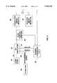
- FIG. 1is schematic block diagram of the present invention beam borrowing system for providing enhanced resolution and reduced banding effects in a laser printer.
- FIG. 2is a schematic control block diagram showing signal paths of the present invention.
- FIG. 3is a magnified wingding "pplus" symbol at conventional 300 dpi binary.
- FIG. 4is a magnified wingding "pplus" symbol at conventional 300 dpi gray scale.
- FIG. 5is a magnified wingding "pplus" symbol at 300 dpi gray scale, and showing the beam borrowing method of the present invention.
- FIG. 6is a magnified wingding "pplus" symbol at 300 dpi gray scale, further showing beam borrowing of the present invention.
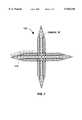
- FIG. 7is a magnified wingding "pplus" symbol at 300 dpi gray scale and completely imaged using beam borrowing of the present invention.
- FIG. 8is a magnified wingding "pplus" symbol at conventional 600 dpi gray scale.
- FIG. 1is schematic block diagram of the present invention beam borrowing system 10 for providing enhanced resolution and reduced banding effects in a laser printer.
- Laser diode 15directs a laser beam 20 through secondary beam deflector (actuator) 25.
- deflector 25is a two axis deflector.
- two single axis deflectors(not shown) arranged orthogonally in the laser beam path could similarly be used.
- Deflector 25provides the beam deflecting (bending/borrowing) capability necessary for the present invention.
- deflector 25is located between laser 15 and polygon scanner (primary deflector) 30 in order to limit the aperture size required in the deflector.
- a beam deflectorcan in principle be mechanical in nature, operating for example by mechanically translating the diode laser relative to its collection lens, or by tilting a beam steering mirror.
- deflector 25is an electro-optic (EO) modulator well known in the art to provide the best combination of frequency, deflection angle range, efficiency and flexibility of operation.
- deflector 25preferably includes both analog and digital channels--an analog channel for banding correction beam deflecting, and a digital channel for resolution enhancement beam borrowing. Modulator 25 is controlled by a flexible electrical function generator to maintain frequency and phase relationships between the deflection of the beam and the on-off modulation of laser 15.
- Rotating scanning mirror 30deflects the beam through lens 35 to scan a focused spot across folding mirror 40 and imaging surface (drum) 45.
- Beams 20a and 20bare both shown to demonstrate the endpoints of the path of beam 20 as it scans across drum 45 responsive to rotating scanning mirror 30.
- photoconductive drum 45is shown, it will be obvious that other media of transfer, such as a continuous belt (not shown), could just as easily be used in place of drum 45.
- Beam position detector (sensor/encoder) 50senses the beam position in the scan direction, as conventional in the art, and is also used in the present invention to sense beam motion in the process direction to close the loop on intended positioning for beam deflecting by modulator 25. Namely, detector 50 sends a signal back to modulator 25 indicating a beam coordinate position for determination of where the beam is relative to where the beam should be detected, for subsequent deflection, if any, whether the deflection relates to resolution enhancement or banding correction.
- Rotational error detector 55detects rotational errors of drum 45 due to gear noise or other sources, and transmits a rotational positioning signal back to modulator 25 for banding correction purposes.
- Translational error detector 60detects motion between the optics unit and drum 45, and transmits a translational positioning signal back to modulator 25, also for banding correction purposes.
- Deflector 25offers two mechanisms for the correction of periodic and impulsive banding: (1) because spot placement is affected by the phase (timing) of the laser modulation relative to a cross-track (cross-scan) dithering motion created by driving the deflector with a suitable waveform, the position of the spot may be varied by advancing or retarding the phase of the laser modulation relative to the phase of the x-y axis deflector, subject to limitations imposed by the particular trajectory chosen; and (2) because the beam deflector has DC to approximately 100 Mhz response, a slowly varying bias term may be added to the basic modulation frequency for x-y banding correction.
- Drum position detectors 55 and 60provide appropriate positioning information
- beam position detector 50provides closed-loop control for exact beam placement.
- FIG. 2a schematic control block diagram shows signal paths of the present invention. Like components retain like references throughout the Figures.
- Laser diode 15is shown transmitting beam 20 through EO modulator 25, to beam position detector 50, and to translation error detector 60.
- Modulator 25 and banding correction circuit 90each receive beam borrowing digital signal 80 from print formatter 85.
- Modulator 25also receives an analog signal 95 from banding correction circuit 90.
- Banding correction circuit 90receives position signals from beam position detector 50, rotation error detector 55, and translation error detector 60. Feedback from the rotational and translational error detectors is summed and used to drive the analog channel of the EO modulator for banding reduction. As a result, the beam is advanced or retarded based on drum position.
- Some of the benefits of the present invention system 10 for enhanced scanning techniquesincludes:
- FIGS. 3, 4 and 8represent variations of a magnified wingding "pplus” for demonstrating conventional imaging technology and for comparison with FIGS. 5-7 which demonstrate the beam deflecting ("borrowing") imaging method of the present invention.
- the wingding "pplus”is used for a combination of horizontal, vertical, and low angle lines as well as for ease of illustration.
- the Figuresdemonstrate the relative ability of each technology to position photons (dots) on a photoconductive drum. Dot diameter represents laser pulse width/power. Variations in the dot diameters represent gray scale levels. Furthermore, as is well understood in electrophotographic art, the dots are not actually round as depicted, nor do they develop as such. However, the ability to accurately position the beam for placement of the dots is directly related to final image quality.
- a wingding "pplus” symbol 110is shown, at 100 ⁇ magnification, demonstrating conventional 300 dpi binary output.
- Dashed lines 115show the desired pattern for "pplus” symbol 110.
- Each dot 120represents a laser pulse to which toner is attracted (only a few dots are reference labeled).
- Dots 1 20fill in desired pattern 115 and form the "pplus” symbol as actually printed.
- the 100 ⁇ magnificationclearly shows why the point of the "pplus” is not pointed using conventional 300 dpi binary technology. It is also clear how dots 120 overlap desired pattern 115, creating a slight margin of error relative to desired patter 115 and thereby forming a slightly off-sized image.
- FIG. 4is a wingding "pplus" symbol 125 at 100 ⁇ magnification, showing conventional 300 dpi technology in combination with gray scale. Desired shape 115 is the same as in FIG. 3. Dots 120 represent a conventionally sized 300 dpi dot similar to those shown in FIG. 3. Dots 130 represent gray scale (reduced size) dots. As is obvious from the drawing, gray scale provides an improved image over conventional imaging. Namely, the points of the "pplus" are better defined and the edges are more accurately defined, relative to desired shape 115, because of the ability to selectively reduce the size of the dots.
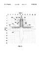
- FIGS. 5 and 6are a wingding "pplus” symbol 150 partially imaged at 100 ⁇ magnification, showing conventional 300 dpi technology and gray scale in combination with the novel beam borrowing method of the present invention.
- the gridis shown for visual clarification in identifying the imaging steps for the "pplus” symbol, and also for identifying base resolution, i.e., the locations where a dot could be placed using conventional base 300 dpi technology.
- the y axis grid linesrepresent the image process direction (i.e., photoconductive drum roll direction or movement of the paper being printed)
- the x axis grid linesrepresent the scan direction (i.e., conventional movement of the laser beam across the length of the drum).
- Beam borrowing of the present inventionenhances edge definition of characters and images in each color plane by "borrowing the beam” from adjacent white space where the beam is not needed (during normal scanning) and applying it to where it is needed at the edge of an image (since it's in the "neighborhood” anyway).
- the beamis borrowed by deflecting it with an electro-optic modulator (see FIG. 1) placed between the laser diode and the scanner.
- the beamis deflected from a given scan line to an offset position or positions relative to the scan direction and/or the processing direction and then, optionally, returned to its normal scan course.
- An edgeis defined as the boundary between an area of color and white space, or in other words, between an area that is charged to attract toner and an area that does not attract toner.
- Beam borrowingtakes advantage of the adjacent white space by borrowing the beam from its normal scan course and using it to produce 2 ⁇ the base printer dot resolution at the edges of the image.
- FIGS. 5-7demonstrate how the edges of the "pplus" symbol are enhanced (doubled) from 300 dpi gray scale resolution to 600 dpi resolution using beam borrowing and gray scale. The Figures also show how dots can be positioned in both process and scan directions for resolution doubling at the edges.
- white spaceis detected or recognized adjacent an image edge by referencing a stored memory map of the image.
- the memory mapidentifies the dot locations defining the image and, similarly, white space locations.
- other methods of white space detectionmay likewise be used.
- FIG. 5shows the printing of lines zero (0) through nine (9) of "pplus” 150, although for clarity of depiction, only lines 3, 4, and 9 are drawn showing exemplary scan paths and "borrowed" dots.
- the laser beamscans the drum at line 3 (the current scan line) in the scan direction
- one embodiment of the directional path (trajectory) of the beamis shown at 162.
- row 9is detected (via the memory map) as being a white space adjacent a left edge of the vertical arm of "pplus" 150.
- the beamis borrowed and offset one row over and one half line down so that dot 156 is placed at offset position row 10 and mid way between scan lines 3 and 4.
- the beamreturns to its projected path to continue scanning line 3, and a conventional dot is placed at its native position at row 11, line 3.
- the conventional scan path of the laser beam along a scan lineis considered here the projected path. Any deflection of the beam from that projected path constitutes a deflection to an offset position.
- line 4is similarly scanned along path 163. Dots 158 and 159 of line 4 are borrowed, when their respective white spaces are detected, and placed one row over and one half line down.
- dots 155 at rows three through nine (3-9) and thirteen through nineteen (13-19)are not needed because they are white space with respect to the desired image 115 of "pplus” 150. However, they are adjacent to the top edge of the left and right arms of "pplus” 150 and are therefore printed one line down and one half row over by "borrowing" the beam during the scan of line nine. Phantom dots 155 at rows 3-9 on line nine (not all are labeled), and the arrows pointing from each phantom dot to line 10, represent how these dots are "borrowed”. Due to the depiction of scan path 164, it is more difficult to see how phantom dots 155 at rows 13-19 are borrowed.
- each of these dotsis borrowed, effectively, one line down and one row over to the left, rather than to the right, as occurred in dots 155 at rows 3-9. Since all these dots 155 are printed at one half row offset on line 10 they provide the basis for forming a double density (600 dpi in this example) top edge along the left and right arms of "pplus” 150. Dots 160 at rows ten through twelve (10-12) of line nine are printed in their native positions, as conventionally occurs, to form the base of the top arm of "pplus” 150.
- FIG. 6shows the printing of line ten. Dots 165 at rows four through eighteen are printed in their native positions. The resultant effect is each dot 165 overlaps with each "borrowed" dot 155 that was previously printed on line ten during the scanning of line nine. This combination of borrowed dots 155 from line nine plus native dots 165 from line ten produce 600 dpi resolution at the edge, where it is needed.
- dots 170 at rows one through four (1-4) and nineteen through twenty-two (19-22)are not needed because they are white space with respect to the desired image 115 of "pplus” 150. However, they are detected as being adjacent to the edge of the left and right points of "pplus” 150 and are therefore borrowed by line eleven, i.e., offset printed one line down and one half row over during the scan of line 10. Phantom dots 170 on line ten, and the arrows pointing from each phantom dot to line 11, represent how the dots are "borrowed”.
- the present invention methodshifts the dots appropriately to effectively double the resolution at the edge of the image being printed. Furthermore, as previously mentioned, this borrowing occurs using the beam bending capability of modulator 25 (see FIG. 1), or similar deflection device.
- FIG. 7is a magnified wingding "pplus" symbol 150 at 300 dpi gray scale, and completely imaged using beam borrowing of the present invention. It is obvious that beam borrowing produces a significantly improved image over conventional technology (compare to FIG. 4 showing 300 dpi gray scale without beam borrowing). It is also obvious that beam borrowing produces an image quality similar to that produced by conventional imaging technology of double the resolution.
- FIG. 8is a magnified wingding "pplus” symbol 175 at conventional 600 dpi gray scale, and represents a 2 ⁇ resolution over the base 300 dpi of FIG. 7 (and also FIG. 4). Although neither technique is capable of rendering the desired pattern 115 perfectly, they are each quite similar in final output quality.
- beam borrowing of the present inventionis just as equally applicable to other dpi technologies, such as 1200 dpi.
- beam borrowing/deflectingreduces memory requirements by half for substantially equivalent image performance. Furthermore, processing requirements are reduced by half because of the virtual processing of multiple scan lines at once.
- beam borrowingdelivers character edge quality enhancement equivalent to that obtained by doubling the resolution of the print engine while doubling the page rate and requiring only half as much memory and half of the scanner speed.
Landscapes
- Physics & Mathematics (AREA)
- Engineering & Computer Science (AREA)
- Optics & Photonics (AREA)
- General Physics & Mathematics (AREA)
- General Engineering & Computer Science (AREA)
- Theoretical Computer Science (AREA)
- Multimedia (AREA)
- Signal Processing (AREA)
- Facsimile Scanning Arrangements (AREA)
- Laser Beam Printer (AREA)
- Mechanical Optical Scanning Systems (AREA)
Abstract
Description
Claims (27)
Priority Applications (4)
| Application Number | Priority Date | Filing Date | Title |
|---|---|---|---|
| US08/528,488US5920336A (en) | 1995-09-12 | 1995-09-12 | Beam deflecting for resolution enhancement and banding reduction in a laser printer |
| EP96103991AEP0763762B1 (en) | 1995-09-12 | 1996-03-13 | Beam deflecting for resolution enhancement and banding reduction in a laser printer |
| DE69615626TDE69615626T2 (en) | 1995-09-12 | 1996-03-13 | Beam deflection to improve resolution and reduce streaking in a laser printer |
| JP23372796AJP3333094B2 (en) | 1995-09-12 | 1996-09-04 | Method and system for improving the performance of a laser beam in an image transfer device |
Applications Claiming Priority (1)
| Application Number | Priority Date | Filing Date | Title |
|---|---|---|---|
| US08/528,488US5920336A (en) | 1995-09-12 | 1995-09-12 | Beam deflecting for resolution enhancement and banding reduction in a laser printer |
Publications (1)
| Publication Number | Publication Date |
|---|---|
| US5920336Atrue US5920336A (en) | 1999-07-06 |
Family
ID=24105879
Family Applications (1)
| Application Number | Title | Priority Date | Filing Date |
|---|---|---|---|
| US08/528,488Expired - LifetimeUS5920336A (en) | 1995-09-12 | 1995-09-12 | Beam deflecting for resolution enhancement and banding reduction in a laser printer |
Country Status (4)
| Country | Link |
|---|---|
| US (1) | US5920336A (en) |
| EP (1) | EP0763762B1 (en) |
| JP (1) | JP3333094B2 (en) |
| DE (1) | DE69615626T2 (en) |
Cited By (13)
| Publication number | Priority date | Publication date | Assignee | Title |
|---|---|---|---|---|
| US20010048461A1 (en)* | 2000-05-31 | 2001-12-06 | Junichi Noguchi | Image forming apparatus and laser drive control method therein |
| US20020196725A1 (en)* | 2001-06-26 | 2002-12-26 | Marshall Daniel R. | Ultra-high density storage device with electron beam steering |
| US6523924B1 (en) | 2001-08-16 | 2003-02-25 | Lexmark International, Inc. | Printer method for reducing effect of paper feed errors |
| US20030227495A1 (en)* | 2002-06-07 | 2003-12-11 | Samii Mohammad M. | Fluid ejection and scanning assembly with photosensor activation of ejection elements |
| US6705701B2 (en) | 2002-06-07 | 2004-03-16 | Hewlett-Packard Development Company, L.P. | Fluid ejection and scanning system with photosensor activation of ejection elements |
| US6735163B2 (en) | 2001-03-02 | 2004-05-11 | Hewlett-Packard Development Company, L.P. | Ultra-high density storage device with resonant scanning micromover |
| US6747684B2 (en) | 2002-04-10 | 2004-06-08 | Hewlett-Packard Development Company, L.P. | Laser triggered inkjet firing |
| US6799819B2 (en) | 2002-06-07 | 2004-10-05 | Hewlett-Packard Development Company, L.P. | Photosensor activation of an ejection element of a fluid ejection device |
| US20040212671A1 (en)* | 2003-04-25 | 2004-10-28 | Simpson Shell S. | Methods and apparatus for selecting image enhancement techniques |
| US20060071963A1 (en)* | 2004-09-30 | 2006-04-06 | Xerox Corporation | Method and system for automatically compensating for diagnosed banding defects prior to the performance of remedial service |
| US7104623B2 (en) | 2002-06-07 | 2006-09-12 | Hewlett-Packard Development Company, L.P. | Fluid ejection system with photosensor activation of ejection element |
| US20070052991A1 (en)* | 2005-09-08 | 2007-03-08 | Xerox Corporation | Methods and systems for determining banding compensation parameters in printing systems |
| US7564475B1 (en) | 2008-03-28 | 2009-07-21 | Xerox Corporation | Compensation of high frequency banding in printing systems |
Families Citing this family (5)
| Publication number | Priority date | Publication date | Assignee | Title |
|---|---|---|---|---|
| GB2342526B (en)* | 1995-09-29 | 2000-06-21 | Asahi Optical Co Ltd | Synchronising signal generating circuit for optical multiple-scanning device |
| US5929892A (en)* | 1996-08-26 | 1999-07-27 | Hewlett-Packard Company | Beam deflecting for enhanced laser printer scanning |
| US6025922A (en)* | 1998-12-18 | 2000-02-15 | Electronics For Imaging | Reduction of banding in printed images |
| DE10024079A1 (en) | 2000-05-17 | 2001-11-22 | Asclepion Meditec Ag | Determining energy and position of pulsed laser beam of ophthalmologic excimer laser for cornea surgery, deflects beam periodically onto measurement sensor |
| EP3711966B1 (en)* | 2019-03-20 | 2021-12-15 | Alltec Angewandte Laserlicht Technologie GmbH | Method for applying a marking on an object and marking apparatus |
Citations (16)
| Publication number | Priority date | Publication date | Assignee | Title |
|---|---|---|---|---|
| US3573449A (en)* | 1968-10-21 | 1971-04-06 | Sperry Rand Corp | Optical pulse expansion system |
| US3653067A (en)* | 1970-12-16 | 1972-03-28 | Bell Telephone Labor Inc | High-speed printing apparatus |
| US4080528A (en)* | 1976-04-23 | 1978-03-21 | Recognition Equipment Incorporated | Data interlacing system |
| US4213704A (en)* | 1977-12-19 | 1980-07-22 | The Singer Company | Method and apparatus for sensing the position of a writing laser beam |
| US4437122A (en)* | 1981-09-12 | 1984-03-13 | Xerox Corporation | Low resolution raster images |
| US4761662A (en)* | 1985-08-20 | 1988-08-02 | Canon Kabushiki Kaisha | Image forming apparatus comprising an image bearing member driven at a predetermined constant speed |
| US4847641A (en)* | 1988-08-16 | 1989-07-11 | Hewlett-Packard Company | Piece-wise print image enhancement for dot matrix printers |
| US4893135A (en)* | 1988-09-23 | 1990-01-09 | Eastman Kodak Company | Laser printer with position registration enhancement |
| US4989941A (en)* | 1988-03-18 | 1991-02-05 | The United States Of America As Represented By The Secretary Of The Air Force | Normal incidence optical switches using ferroelectric liquid crystals |
| US5005139A (en)* | 1988-08-16 | 1991-04-02 | Hewlett-Packard Company | Piece-wise print image enhancement for dot matrix printers |
| US5083140A (en)* | 1990-04-10 | 1992-01-21 | Minnesota Mining And Manufacturing Company | Multiple charge images initiation with scan synchronization |
| US5315322A (en)* | 1990-02-21 | 1994-05-24 | Ricoh Company, Ltd. | Image forming apparatus with anti-banding implementation |
| DE4300739A1 (en)* | 1992-12-22 | 1994-06-30 | Agfa Gevaert Ag | Cross-scan fault position error correction for laser printer |
| US5424780A (en)* | 1989-05-22 | 1995-06-13 | Cooper; James C. | Apparatus and method for spacial scan modulation of a video display |
| US5453851A (en)* | 1992-07-31 | 1995-09-26 | E. I. Du Pont De Nemours And Company | Error reduction methods in scanning systems |
| US5592207A (en)* | 1991-09-20 | 1997-01-07 | Hitachi, Ltd. | Optical recording apparatus |
Family Cites Families (3)
| Publication number | Priority date | Publication date | Assignee | Title |
|---|---|---|---|---|
| US4445125A (en)* | 1982-04-19 | 1984-04-24 | Xerox Corporation | Diode laser array system for printing and copying applications |
| US4707709A (en)* | 1986-01-17 | 1987-11-17 | Eastman Kodak Company | Image recording apparatus in which exposure levels are a function of image contents |
| JPH0782156B2 (en)* | 1986-05-23 | 1995-09-06 | 株式会社日立製作所 | Recording optics |
- 1995
- 1995-09-12USUS08/528,488patent/US5920336A/ennot_activeExpired - Lifetime
- 1996
- 1996-03-13DEDE69615626Tpatent/DE69615626T2/ennot_activeExpired - Lifetime
- 1996-03-13EPEP96103991Apatent/EP0763762B1/ennot_activeExpired - Lifetime
- 1996-09-04JPJP23372796Apatent/JP3333094B2/ennot_activeExpired - Fee Related
Patent Citations (18)
| Publication number | Priority date | Publication date | Assignee | Title |
|---|---|---|---|---|
| US3573449A (en)* | 1968-10-21 | 1971-04-06 | Sperry Rand Corp | Optical pulse expansion system |
| US3653067A (en)* | 1970-12-16 | 1972-03-28 | Bell Telephone Labor Inc | High-speed printing apparatus |
| US4080528A (en)* | 1976-04-23 | 1978-03-21 | Recognition Equipment Incorporated | Data interlacing system |
| US4213704A (en)* | 1977-12-19 | 1980-07-22 | The Singer Company | Method and apparatus for sensing the position of a writing laser beam |
| US4437122A (en)* | 1981-09-12 | 1984-03-13 | Xerox Corporation | Low resolution raster images |
| US4437122B1 (en)* | 1981-09-12 | 1993-03-30 | Xerox Corp | |
| US4761662A (en)* | 1985-08-20 | 1988-08-02 | Canon Kabushiki Kaisha | Image forming apparatus comprising an image bearing member driven at a predetermined constant speed |
| US4989941A (en)* | 1988-03-18 | 1991-02-05 | The United States Of America As Represented By The Secretary Of The Air Force | Normal incidence optical switches using ferroelectric liquid crystals |
| US5005139A (en)* | 1988-08-16 | 1991-04-02 | Hewlett-Packard Company | Piece-wise print image enhancement for dot matrix printers |
| US4847641A (en)* | 1988-08-16 | 1989-07-11 | Hewlett-Packard Company | Piece-wise print image enhancement for dot matrix printers |
| US4893135A (en)* | 1988-09-23 | 1990-01-09 | Eastman Kodak Company | Laser printer with position registration enhancement |
| US5424780A (en)* | 1989-05-22 | 1995-06-13 | Cooper; James C. | Apparatus and method for spacial scan modulation of a video display |
| US5424780C1 (en)* | 1989-05-22 | 2002-07-23 | James C Cooper | Apparatus and method for special scan modulation of a video display |
| US5315322A (en)* | 1990-02-21 | 1994-05-24 | Ricoh Company, Ltd. | Image forming apparatus with anti-banding implementation |
| US5083140A (en)* | 1990-04-10 | 1992-01-21 | Minnesota Mining And Manufacturing Company | Multiple charge images initiation with scan synchronization |
| US5592207A (en)* | 1991-09-20 | 1997-01-07 | Hitachi, Ltd. | Optical recording apparatus |
| US5453851A (en)* | 1992-07-31 | 1995-09-26 | E. I. Du Pont De Nemours And Company | Error reduction methods in scanning systems |
| DE4300739A1 (en)* | 1992-12-22 | 1994-06-30 | Agfa Gevaert Ag | Cross-scan fault position error correction for laser printer |
Cited By (22)
| Publication number | Priority date | Publication date | Assignee | Title |
|---|---|---|---|---|
| US20010048461A1 (en)* | 2000-05-31 | 2001-12-06 | Junichi Noguchi | Image forming apparatus and laser drive control method therein |
| US6714231B2 (en)* | 2000-05-31 | 2004-03-30 | Canon Kabushiki Kaisha | Image forming apparatus and laser drive control method therein |
| US6735163B2 (en) | 2001-03-02 | 2004-05-11 | Hewlett-Packard Development Company, L.P. | Ultra-high density storage device with resonant scanning micromover |
| US20020196725A1 (en)* | 2001-06-26 | 2002-12-26 | Marshall Daniel R. | Ultra-high density storage device with electron beam steering |
| US6930971B2 (en) | 2001-06-26 | 2005-08-16 | Hewlett-Packard Development Company, L.P. | Ultra-high density storage device with electron beam steering |
| US6523924B1 (en) | 2001-08-16 | 2003-02-25 | Lexmark International, Inc. | Printer method for reducing effect of paper feed errors |
| US6747684B2 (en) | 2002-04-10 | 2004-06-08 | Hewlett-Packard Development Company, L.P. | Laser triggered inkjet firing |
| DE10315511B4 (en)* | 2002-04-10 | 2017-12-14 | Hewlett-Packard Development Company, L.P. | Printhead and printing system for laser-controlled ink-jet firing |
| US7104623B2 (en) | 2002-06-07 | 2006-09-12 | Hewlett-Packard Development Company, L.P. | Fluid ejection system with photosensor activation of ejection element |
| US6705701B2 (en) | 2002-06-07 | 2004-03-16 | Hewlett-Packard Development Company, L.P. | Fluid ejection and scanning system with photosensor activation of ejection elements |
| US20030227495A1 (en)* | 2002-06-07 | 2003-12-11 | Samii Mohammad M. | Fluid ejection and scanning assembly with photosensor activation of ejection elements |
| US6893113B2 (en) | 2002-06-07 | 2005-05-17 | Hewlett-Packard Development Company, L.P. | Fluid ejection and scanning system with photosensor activation of ejection elements |
| US20040066423A1 (en)* | 2002-06-07 | 2004-04-08 | Samii Mohammad M. | Fluid ejection and scanning system with photosensor activation of ejection elements |
| US6799819B2 (en) | 2002-06-07 | 2004-10-05 | Hewlett-Packard Development Company, L.P. | Photosensor activation of an ejection element of a fluid ejection device |
| US7083250B2 (en) | 2002-06-07 | 2006-08-01 | Hewlett-Packard Development Company, L.P. | Fluid ejection and scanning assembly with photosensor activation of ejection elements |
| US7422310B2 (en) | 2003-04-25 | 2008-09-09 | Hewlett-Packard Development Company, L.P. | Methods and apparatus for selecting image enhancement techniques |
| US20040212671A1 (en)* | 2003-04-25 | 2004-10-28 | Simpson Shell S. | Methods and apparatus for selecting image enhancement techniques |
| US20060071963A1 (en)* | 2004-09-30 | 2006-04-06 | Xerox Corporation | Method and system for automatically compensating for diagnosed banding defects prior to the performance of remedial service |
| US7400339B2 (en) | 2004-09-30 | 2008-07-15 | Xerox Corporation | Method and system for automatically compensating for diagnosed banding defects prior to the performance of remedial service |
| US20070052991A1 (en)* | 2005-09-08 | 2007-03-08 | Xerox Corporation | Methods and systems for determining banding compensation parameters in printing systems |
| US7911652B2 (en) | 2005-09-08 | 2011-03-22 | Xerox Corporation | Methods and systems for determining banding compensation parameters in printing systems |
| US7564475B1 (en) | 2008-03-28 | 2009-07-21 | Xerox Corporation | Compensation of high frequency banding in printing systems |
Also Published As
| Publication number | Publication date |
|---|---|
| EP0763762B1 (en) | 2001-10-04 |
| DE69615626D1 (en) | 2001-11-08 |
| DE69615626T2 (en) | 2002-09-05 |
| JPH09123525A (en) | 1997-05-13 |
| EP0763762A1 (en) | 1997-03-19 |
| JP3333094B2 (en) | 2002-10-07 |
Similar Documents
| Publication | Publication Date | Title |
|---|---|---|
| US5920336A (en) | Beam deflecting for resolution enhancement and banding reduction in a laser printer | |
| US5929892A (en) | Beam deflecting for enhanced laser printer scanning | |
| EP0526000B1 (en) | Microaddressability via overscanned illumination for optical printers and the like having high gamma photosensitive recording media | |
| US5430472A (en) | Method and apparatus for eliminating distortion via overscanned illumination for optical printers and the like having high gamma photosensitive recording media and high addressability | |
| US5103334A (en) | Resolution improvement in flying spot scanner | |
| EP0875386B1 (en) | Improvements in or relating to printing | |
| JP2783328B2 (en) | Image forming device | |
| EP0529785B1 (en) | Raster output scanner with process direction spot position control | |
| US5581292A (en) | Method and apparatus for enhancing charged area developed regions in a tri-level printing system | |
| EP0893780B1 (en) | Method for resolution conversion of print data for a printer | |
| US5367381A (en) | Method and apparatus for enhanced resolution and contrast via super intensity controlled overscanned illumination in a two dimensional high addressability printer | |
| JP4268026B2 (en) | Image forming apparatus | |
| US5274397A (en) | Large-format plotter using segmented raster-scanning | |
| JP3246754B2 (en) | Optical recording device and information processing system | |
| JP3098666B2 (en) | Image forming device | |
| JP4326522B2 (en) | Laser printer with reduced banding artifacts | |
| US20080285987A1 (en) | Electrophotographic Device Utilizing Multiple Laser Sources | |
| JP3419502B2 (en) | How to remove optical printer distortion | |
| JP3254275B2 (en) | Image recording device | |
| JP3143489B2 (en) | Image forming apparatus and method | |
| JPH0691930A (en) | Method and device for improving resolution and contrast of optical printer | |
| JP2005001122A (en) | Image forming apparatus | |
| JPH03274170A (en) | Pulse forming device of image signal | |
| JPH09193454A (en) | Image forming device | |
| JPH07240848A (en) | Method for producing color separation halftone plate prevented in generation of moire |
Legal Events
| Date | Code | Title | Description |
|---|---|---|---|
| AS | Assignment | Owner name:HEWLETT-PACKARD COMPANY, CALIFORNIA Free format text:ASSIGNMENT OF ASSIGNORS INTEREST;ASSIGNORS:LAWTON, ROBERT J.;MARSHALL, DANIEL R.;REEL/FRAME:007719/0057;SIGNING DATES FROM 19950311 TO 19950911 | |
| STCF | Information on status: patent grant | Free format text:PATENTED CASE | |
| AS | Assignment | Owner name:HEWLETT-PACKARD COMPANY, COLORADO Free format text:MERGER;ASSIGNOR:HEWLETT-PACKARD COMPANY;REEL/FRAME:011523/0469 Effective date:19980520 | |
| FEPP | Fee payment procedure | Free format text:PAYOR NUMBER ASSIGNED (ORIGINAL EVENT CODE: ASPN); ENTITY STATUS OF PATENT OWNER: LARGE ENTITY | |
| FPAY | Fee payment | Year of fee payment:4 | |
| FPAY | Fee payment | Year of fee payment:8 | |
| REMI | Maintenance fee reminder mailed | ||
| SULP | Surcharge for late payment | Year of fee payment:7 | |
| FPAY | Fee payment | Year of fee payment:12 | |
| AS | Assignment | Owner name:HEWLETT-PACKARD DEVELOPMENT COMPANY, L.P., TEXAS Free format text:ASSIGNMENT OF ASSIGNORS INTEREST;ASSIGNOR:HEWLETT-PACKARD COMPANY;REEL/FRAME:026945/0699 Effective date:20030131 |