US5920319A - Automatic analysis in virtual endoscopy - Google Patents
Automatic analysis in virtual endoscopyDownload PDFInfo
- Publication number
- US5920319A US5920319AUS08/805,584US80558497AUS5920319AUS 5920319 AUS5920319 AUS 5920319AUS 80558497 AUS80558497 AUS 80558497AUS 5920319 AUS5920319 AUS 5920319A
- Authority
- US
- United States
- Prior art keywords
- dimensional
- volume
- recited
- interest
- grouping
- Prior art date
- Legal status (The legal status is an assumption and is not a legal conclusion. Google has not performed a legal analysis and makes no representation as to the accuracy of the status listed.)
- Expired - Lifetime
Links
Images


Classifications
- G—PHYSICS
- G06—COMPUTING OR CALCULATING; COUNTING
- G06T—IMAGE DATA PROCESSING OR GENERATION, IN GENERAL
- G06T7/00—Image analysis
- G06T7/0002—Inspection of images, e.g. flaw detection
- G06T7/0012—Biomedical image inspection
- A—HUMAN NECESSITIES
- A61—MEDICAL OR VETERINARY SCIENCE; HYGIENE
- A61B—DIAGNOSIS; SURGERY; IDENTIFICATION
- A61B5/00—Measuring for diagnostic purposes; Identification of persons
- A61B5/103—Measuring devices for testing the shape, pattern, colour, size or movement of the body or parts thereof, for diagnostic purposes
- A61B5/107—Measuring physical dimensions, e.g. size of the entire body or parts thereof
- A61B5/1076—Measuring physical dimensions, e.g. size of the entire body or parts thereof for measuring dimensions inside body cavities, e.g. using catheters
- G—PHYSICS
- G06—COMPUTING OR CALCULATING; COUNTING
- G06T—IMAGE DATA PROCESSING OR GENERATION, IN GENERAL
- G06T15/00—3D [Three Dimensional] image rendering
- G06T15/08—Volume rendering
- G—PHYSICS
- G06—COMPUTING OR CALCULATING; COUNTING
- G06T—IMAGE DATA PROCESSING OR GENERATION, IN GENERAL
- G06T17/00—Three dimensional [3D] modelling, e.g. data description of 3D objects
- G—PHYSICS
- G06—COMPUTING OR CALCULATING; COUNTING
- G06T—IMAGE DATA PROCESSING OR GENERATION, IN GENERAL
- G06T17/00—Three dimensional [3D] modelling, e.g. data description of 3D objects
- G06T17/20—Finite element generation, e.g. wire-frame surface description, tesselation
- G—PHYSICS
- G06—COMPUTING OR CALCULATING; COUNTING
- G06T—IMAGE DATA PROCESSING OR GENERATION, IN GENERAL
- G06T7/00—Image analysis
- G06T7/10—Segmentation; Edge detection
- G06T7/11—Region-based segmentation
- G—PHYSICS
- G06—COMPUTING OR CALCULATING; COUNTING
- G06T—IMAGE DATA PROCESSING OR GENERATION, IN GENERAL
- G06T7/00—Image analysis
- G06T7/10—Segmentation; Edge detection
- G06T7/155—Segmentation; Edge detection involving morphological operators
- G—PHYSICS
- G09—EDUCATION; CRYPTOGRAPHY; DISPLAY; ADVERTISING; SEALS
- G09B—EDUCATIONAL OR DEMONSTRATION APPLIANCES; APPLIANCES FOR TEACHING, OR COMMUNICATING WITH, THE BLIND, DEAF OR MUTE; MODELS; PLANETARIA; GLOBES; MAPS; DIAGRAMS
- G09B23/00—Models for scientific, medical, or mathematical purposes, e.g. full-sized devices for demonstration purposes
- G09B23/28—Models for scientific, medical, or mathematical purposes, e.g. full-sized devices for demonstration purposes for medicine
- G09B23/285—Models for scientific, medical, or mathematical purposes, e.g. full-sized devices for demonstration purposes for medicine for injections, endoscopy, bronchoscopy, sigmoidscopy, insertion of contraceptive devices or enemas
- G—PHYSICS
- G06—COMPUTING OR CALCULATING; COUNTING
- G06T—IMAGE DATA PROCESSING OR GENERATION, IN GENERAL
- G06T2207/00—Indexing scheme for image analysis or image enhancement
- G06T2207/10—Image acquisition modality
- G06T2207/10072—Tomographic images
- G06T2207/10081—Computed x-ray tomography [CT]
- G—PHYSICS
- G06—COMPUTING OR CALCULATING; COUNTING
- G06T—IMAGE DATA PROCESSING OR GENERATION, IN GENERAL
- G06T2207/00—Indexing scheme for image analysis or image enhancement
- G06T2207/20—Special algorithmic details
- G06T2207/20004—Adaptive image processing
- G06T2207/20012—Locally adaptive
- G—PHYSICS
- G06—COMPUTING OR CALCULATING; COUNTING
- G06T—IMAGE DATA PROCESSING OR GENERATION, IN GENERAL
- G06T2207/00—Indexing scheme for image analysis or image enhancement
- G06T2207/30—Subject of image; Context of image processing
- G06T2207/30004—Biomedical image processing
- G06T2207/30028—Colon; Small intestine
- G06T2207/30032—Colon polyp
- G—PHYSICS
- G06—COMPUTING OR CALCULATING; COUNTING
- G06T—IMAGE DATA PROCESSING OR GENERATION, IN GENERAL
- G06T2207/00—Indexing scheme for image analysis or image enhancement
- G06T2207/30—Subject of image; Context of image processing
- G06T2207/30004—Biomedical image processing
- G06T2207/30061—Lung
- G06T2207/30064—Lung nodule
- Y—GENERAL TAGGING OF NEW TECHNOLOGICAL DEVELOPMENTS; GENERAL TAGGING OF CROSS-SECTIONAL TECHNOLOGIES SPANNING OVER SEVERAL SECTIONS OF THE IPC; TECHNICAL SUBJECTS COVERED BY FORMER USPC CROSS-REFERENCE ART COLLECTIONS [XRACs] AND DIGESTS
- Y02—TECHNOLOGIES OR APPLICATIONS FOR MITIGATION OR ADAPTATION AGAINST CLIMATE CHANGE
- Y02A—TECHNOLOGIES FOR ADAPTATION TO CLIMATE CHANGE
- Y02A90/00—Technologies having an indirect contribution to adaptation to climate change
- Y02A90/10—Information and communication technologies [ICT] supporting adaptation to climate change, e.g. for weather forecasting or climate simulation
- Y—GENERAL TAGGING OF NEW TECHNOLOGICAL DEVELOPMENTS; GENERAL TAGGING OF CROSS-SECTIONAL TECHNOLOGIES SPANNING OVER SEVERAL SECTIONS OF THE IPC; TECHNICAL SUBJECTS COVERED BY FORMER USPC CROSS-REFERENCE ART COLLECTIONS [XRACs] AND DIGESTS
- Y10—TECHNICAL SUBJECTS COVERED BY FORMER USPC
- Y10S—TECHNICAL SUBJECTS COVERED BY FORMER USPC CROSS-REFERENCE ART COLLECTIONS [XRACs] AND DIGESTS
- Y10S128/00—Surgery
- Y10S128/92—Computer assisted medical diagnostics
Definitions
- the present inventionrelates to a system and method for interactively displaying a three-dimensional rendering of a structure having a lumen and, more particularly, to a system and method for automatically analyzing such structures for potential abnormalities.
- Virtual endoscopythat utilizes computer reformation of radiologic cross-sectional images is a minimally invasive alternative to conventional fiberoptic endoscopy.
- Virtual endoscopyreduces the risk of perforation, does not require any sedation, and is considerably less expensive than the fiberoptic endoscopy method.
- virtual colonoscopy techniquesgenerally require bowel cleansing, gas distension of the colon, a 40-60 second spiral computed tomography (CT) scan of a patient's abdomen and pelvis, and human visual analysis of multi-planar two-dimensional (2D) and three-dimensional (3D) images created from CT data.
- CTcomputed tomography
- a computer-implemented method and computer systemare provided for interactively displaying a three-dimensional rendering of a structure having a lumen.
- the methodmay be utilized for analyzing regions having certain characteristics of wall structure such as thickness or shape to detect, for example, abnormal masses.
- a three-dimensional volume of datais formed from a series of two-dimensional images representing at least one physical property associated with the three-dimensional object.
- An isosurface of a selected region of interestis created in the computer from the volume of data based on selected values of the physical properties representing the selected region of interest.
- a wireframe model of the isosurfaceis generated by the computer.
- the wireframe modelis analyzed to detect, by computer, those sections of the object having the selected characteristic such as abnormal wall structure.
- the wireframe modelincludes a plurality of vertices.
- the computer-implemented methodgroups the vertices of the wireframe model into populations having a characteristic indicating abnormal wall structure.
- the wireframe model with highlighted abnormal portionsis then rendered by the computer into an interactive three-dimensional display on the computer monitor.
- the step of grouping the vertices into populations having a characteristic indicating abnormal wall structureis effected by determining a normal vertex for each vertex position of the wireframe model.
- a connectivity matrixis determined to provide sets of contiguous vertices for each vertex.
- a wall thickness value associated with each normal vectoris determined for each vertex.
- Local convexity and curvatureare also determined on a per vertex basis.
- contiguous vertices having a characteristic indicating abnormal thicknesses or other abnormal propertiesare grouped together into separate populations indicative of areas of abnormality.
- the computer-implemented methodmay function to analyze shape characteristics of selected populations of vertices.
- each population of contiguous verticesmay be determined based on a characteristic such as convexity or curvature.
- Each populationis then analyzed to determine a convexity value for each population representing an amount and direction of convexity of the population on the wireframe model.
- each populationmay be analyzed according to other selected shape characteristics.
- a method and systemfor interactively displaying a three-dimensional rendering of a structure having a lumen wherein the rendering is effected by a an adaptive thresholding procedure.
- a three-dimensional volume of datais formed in a computer from a series of two-dimensional images acquired, for example, by a scanner such as CT-scanner.
- the acquired imagesrepresent at least one physical property associated with the three-dimensional object.
- a selected region of interestis segmented by the computer from the volume of data based on a selected criteria such as a threshold value of the physical property.
- the threshold valueis adaptively adjusted in the region of interest to control the segmenting of the selected region of interest.
- An isosurface of a selected region of interestis created by the computer from the volume of data based on selected values, such as the adaptive adjusted thresholds of the physical property representing the selected region of interest.
- selected valuessuch as the adaptive adjusted thresholds of the physical property representing the selected region of interest.
- a wireframe model of the isosurfaceis generated and then rendered in an interactive three-dimensional display.
- FIG. 1is a flowchart representing a method in accordance with the present invention of producing an interactive, three-dimensional rendering of a selected organ system, such as a lumenous organ, and of detecting potentially abnormal areas of the organ system;
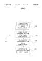
- FIG. 2is a flowchart representing a method for analyzing the shape of a population representing a potentially abnormal area within the selected organ system
- FIG. 3is a flowchart representing a method for measuring the selected organ system's wall thickness
- FIG. 4is a block diagram of a system used in the method of the present invention.
- FIG. 5is a schematic representation of a two-dimensional plane through a wireframe model of an area of abnormal wall structure illustrating a method for determining the convexity of the area;
- FIG. 6is a flowchart representing a method for adaptively adjusting a threshold value during the segmentation of a region of interest
- FIG. 7is a schematic view of a display window for displaying a volume rendered image, a surface rendered image, and three multiplanar images along three different planes of a selected organ system;
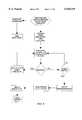
- FIG. 8is flowchart representing a method for determining a central path through the lumen of a hollow organ
- FIG. 9is a schematic view of a display window for displaying a volume rendered image, a surface rendered image, and three multiplanar images along three different planes of a selected organ system combined in a single window display;
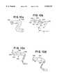
- FIG. 10a-hare schematic illustrations depicting a process for splitting a colon.
- the present inventiongenerally relates to a method and system, as schematically represented in FIGS. 1-4, for generating interactive, three-dimensional renderings of three-dimensional structures generally having a lumen.
- the structuresare usually in the general form of selected regions of a body and in particular, human or animal body organs which have hollow lumens such as colons, blood vessels, and airways.
- the interactive three-dimensional renderingsare generated in a computer-controlled process from a series of two-dimensional, cross-sectional images of the selected body organ acquired, for example, from a helical (computed tomography (CT) Scan.
- CTcomputed tomography
- the three-dimensional renderingsare interactive in that such renderings can be manipulated by a user on a visual display of a computer system, such as a computer monitor, to enable movement in, around and through the three-dimensional structure while simultaneously displaying multiplanar views centered on a point that changes in response to the movement, or on a point selected by the user.
- a computer systemsuch as a computer monitor
- the computer-generated interactive three-dimensional renderingscan be constructed from surface renderings of the organ system or from volume renderings of the organ system and surrounding anatomy and, often, presented simultaneously in the same three-dimensional display window.
- a surface rendering of an organcan be incorporated into a volume rendering of the surrounding anatomy using texture memory in order to achieve a combined surface/volume rendering, or a hybrid rendering effect, wherein the surface rendered organ may be highlighted in the context of the volume-rendered surrounding anatomy.
- multiplanar viewssuch as orthogonal (sagittal, coronal, and axial) or oblique views, may be presented simultaneously with a surface-rendered organ and surrounding volume-rendered anatomy in either separate three-dimensional display windows or in a combined single three-dimensional or display window.
- a computer-controlled system 20 in accordance with the present inventionis shown schematically in FIG. 4.
- the system 20is generally as described in co-pending application Ser. No. 08/331,352, which is incorporated herein by reference.
- a computer console 24is used to operate a scanner 22 to produce a series of two-dimensional, cross-sectional images of a selected three-dimensional object.
- the two-dimensional imagesare transferred from the console 24 to a computer graphics workstation 26 over a computer network 25.
- the graphics computer 26is used to generate a three-dimensional rendering, such as a three dimensional surface rendering, of the selected object and to automatically identify potentially abnormal regions of the structure.
- the three-dimensional renderingis displayed on a computer monitor 28. Additionally, the displayed rendering can be recorded on a video recorder 30 or photographed for future viewing.
- Various inputs, such as a computer mouse 27,are provided to the graphics computer to permit a user to manipulate the displayed imagery.
- the scanner 22can be a General Electric HiSpeed Advantage Helical CT Scanner (GE Medical Systems, Milwaukee, Wis.). For scanning a patient's lungs, the scanner is typically operated with an X-ray beam collimation of 3 mm, a pitch of 1:1, a 1 mm reconstruction interval, a display field-of-view of 25.6 cm, and a 512 ⁇ 512 matrix. For scanning a patient's colon, the scanner is typically operated with a beam collimation of 5 mm, a pitch of 2:1, a 1 mm reconstruction interval, a display field-of-view of 40 cm, and a 512 ⁇ 512 matrix. These protocols typically result in approximately 200 thoracic CT images or 500 abdominal CT images, which occupy approximately 100 MB and 250 MB of disk storage space, respectively. However, the protocols can be modified to optimally acquire image data of specific organ systems.
- GE Medical SystemsMilwaukee, Wis.
- the image datacan be stored in any of a variety of image formats.
- the image datacan be stored in the digital imaging and communications in medicine (DICOM) standard, or as raw binary slices, or in a variety of volume formats.
- the image datacan be stored in the computer memory in an internal data format which allows the image files to be saved as a single data volume instead of individual image files.
- the internal data formatcan also permit standard compression and uncompression techniques to be incorporated, thereby reducing computer disk storage requirements.
- FIG. 1A method for generating interactive, three-dimensional renderings of a selected structure having a lumen and indicating potentially abnormal regions of the structure in accordance with the present invention is generally set forth in FIG. 1.
- the methodcan be implemented by computer.
- the steps of patient preparation 32, acquisition of two-dimensional images 33, formation of a three-dimensional volume 34, segmentation of a region of interest 35, creation of an isosurface of the region of interest 37, and generation of a wireframe model of the isosurface 38may be effected in the general manner described in co-pending application Ser. No. 08/331,352, which is incorporated herein by reference or any comparable methodologies and algorithms.
- Patient preparation 32will be dictated by the organ system to be rendered. For example, if the patient's colon is to be rendered, the patient is prepared using bowel cleansing and insufflation with gas to distend the colon.
- the patientcan be given an oral contrast agent to become incorporated in the fecal content to readily distinguish the stool from surrounding soft tissue structures, including the colon wall. Without adequate bowel cleansing or use of an oral contrast agent, stool and normal colon wall or colon lesions can be indistinguishable in computed tomography or other radiologic modality images.
- the contrast agentmay comprise a low-density (e.g., 1.5% w/v) barium-containing mixture.
- the opacified stoolmay then be digitally substracted from the CT image data in order to render an unimpeded colon.
- the patientcan be administered a bolus of non-ionic intravenous iodinated contrast agent to aid in distinguishing the blood vessels surrounding the airways.
- two dimensional, cross-sectional images of the selected structureare acquired at step 33 with the use of a scanner 22, such as a helical computed tomography (CT) scanner or magnetic resonance imaging (MRI) scanner.
- CTcomputed tomography
- MRImagnetic resonance imaging
- the two-dimensional imagesare arranged in computer memory 21 (i.e., random access memory (RAM)) to create a three-dimensional data volume at step 34.
- RAMrandom access memory
- an interpolation methodincluding but not limited to trilinear interpolation, can be applied.
- a region of interestis segmented from the three-dimensional data volume.
- the purpose of segmentationis to isolate a region of interest within the three-dimensional data volume prior to three-dimensional rendering.
- medical image segmentationis complicated by image noise, partial volume effects, and the fact that similar intensity values are shared by different anatomical structures.
- segmentation of that structurecan be effectuated by selecting the air column as the region of interest.
- the air columncan be effectively segmented because the boundary between air and soft tissue is relatively distinct and sharp. Further, the outside surface of the air column corresponds to the inside surface of the organ of interest.
- a thin-walled soft tissue structureencompasses a contrast enhanced blood-filled lumen
- segmentation of that structurecan be effectuated by selecting the contrast-enhanced blood column as the region of interest. Accordingly, a simple thresholding or region growing technique, along with a morphological dilation away from air or blood vessel and towards soft tissue, can be utilized for segmentation purposes.
- ⁇⁇ ⁇ ⁇ ⁇ ⁇ ⁇ ⁇ ⁇ ⁇ ⁇ ⁇ ⁇ ⁇ ⁇ ⁇ ⁇ ⁇ ⁇ ⁇ ⁇ ⁇ ⁇ ⁇ ⁇ ⁇ ⁇ ⁇ ⁇ ⁇ ⁇ ⁇ ⁇ ⁇ ⁇ ⁇ ⁇ ⁇ ⁇ ⁇ ⁇ ⁇ ⁇ ⁇ ⁇ ⁇ ⁇ ⁇ ⁇ ⁇ ⁇ ⁇ ⁇ ⁇ ⁇ ⁇ ⁇ ⁇ ⁇ ⁇ ⁇ ⁇ ⁇ ⁇ ⁇ ⁇ ⁇ ⁇ ⁇ ⁇ ⁇ ⁇ ⁇ ⁇ ⁇ ⁇ ⁇ ⁇ ⁇ ⁇ ⁇ ⁇ ⁇ ⁇ ⁇ ⁇ ⁇ ⁇ ⁇ ⁇ ⁇ ⁇ ⁇ ⁇ ⁇ ⁇ ⁇ ⁇ ⁇ ⁇ ⁇ ⁇ ⁇ ⁇ ⁇ ⁇ ⁇ ⁇ ⁇ ⁇ ⁇ ⁇ ⁇ ⁇ ⁇ ⁇ ⁇ ⁇ ⁇ ⁇ ⁇ ⁇ ⁇ ⁇ ⁇ ⁇
- a computer-executed method for adaptively adjusting threshold values for the airwaysis shown in FIG. 6.
- the region of interestis segmented using a three-dimensional region growing technique and an initial static threshold value.
- the threshold value chosenshould approach the maximum threshold value which can be selected without having the segmentation procedure fail by including surrounding structures as part of the region of interest. For example, when segmenting the air column of an airway, an initial threshold value of -800 HU may be appropriate.
- An initial wireframe model of the anatomyis created using a marching cubes variant.
- the voxels or volume elements of the segmented region of interestare tagged at step 77 by setting a high-order bit in the 16-bit computer word used to store the voxel values (usually only the lower-order 12 bits of a 16 bit word hold any actual data).
- the tagged voxelsare used to find the boundary and voxel counts in two-dimensions for each airway segment on every image slice.
- the voxels within each boundaryare distinctly re-tagged at step 81 by setting a different high-order bit.
- the vertices on the initial three-dimensional wireframe model closest to each two-dimensional boundary point of each segmentare found.
- An intensity profile along each vertex's normal vectoris calculated to measure x-ray attenuations factors incremental along the normal directions at step 85.
- the intensity profilesextend bidirectionally, into the surrounding tissue until the voxel values begin to decrease, and into the airway lumen until the voxel values begin to increase.
- the adaptive threshold valueis calculated for each segment on every image at step 87 as an average value of several measured threshold values for each segment.
- Each adaptive threshold valuecan be calculated as a variable percentage of the difference between the average maximum and minimum attenuation factors for the corresponding intensity profile. For example, a percentage of 50% corresponds to the full-width-at-half-maximum measure of the intensity profile.
- the adaptive threshold valuesare then used to re-segment the region of interest at step 88 using a region growing process that can account for the varying threshold values.
- the adaptive threshold valuescan be calculated by morphing a ring which represents the intersection of the airway and a perpendicular plane along the skeleton of the airway.
- the skeletonis a sequence of connected points that lie along the center of the air columns, like a central path.
- the initial reference ringlies in the initial perpendicular plane and is the set of iso-value points of an underestimated threshold value on that plane in the largest branch of the airway. Using this ring as a reference, the threshold value is changed to create a new ring in the same plane, with a larger circumference and larger curvature values than the reference ring.
- the old threshold valueis replaced by the new threshold, and the process is repeated.
- the new threshold valueis stored on the skeleton, the perpendicular plane is shifted to the next point on the skeleton, and the previous threshold value is used as the initial threshold value for the iso-value ring on the new plane. This process is repeated for every branch along the skeleton until every point in the skeleton has an associated adaptive threshold value.
- a variant of the marching cubescan then be used to generate a variable-value surface using the variable threshold values.
- Another method for adaptively adjusting the threshold valve used to grow an objectuses the morphological skeleton of an approximate object to choose optimal threshold values for all parts of the final object.
- the objectis first grown using a lower threshold value. This gives the base structure, but usually does not accurately segment all of the object.
- the medial axisis calculated from the morphological skeleton of the object. For each voxel on the medial axis, the algorithm searches out (in bi-directional rays perpendicular to the local axis) the local maxima and minima of voxel values along the search line.
- the full-width-at-half-the-maximum value, or a variable percentage value,is then calculated for each bi-directional ray, and all rays for a particular axis point are averaged to give a threshold value at the axis point.
- the nearest axis point to the current voxelis determined, and the threshold value associated with that point is used to classify the voxel as being inside or outside the object using a region growing procedure.
- Yet another technique for adaptive thresholdinginvolves manually specifying markers in the volume to hold threshold values that best approximate the object at that location.
- the markersare established for all sections of the object that need special threshold values.
- a global threshold valueis also specified.
- the algorithmchecks to see if the current voxel is near a threshold marker. If so, the threshold value associated with the marker is used to classify the voxel as being inside or outside the object.
- the range for calling a position near the marker, as well as the behavior if the position is inside the specified rangecan be user-specified.
- the global thresholdis used to classify the voxel.
- Still another technique for adaptive thresholdingmodifies the threshold value as a function of the distance from the starting seed of the region growing procedure.
- the usermay specify that voxels near the seed should be within a certain range, but voxels farther away from the seed should fall within a different range.
- the thresholds for positions in betweencan be found by interpolating between the ranges. For this technique, any number of distance and threshold ranges can be specified.
- an isosurface of the region of interestis created at step 37.
- the isosurfacecan be generated using a variant of a marching cube algorithm.
- the isosurfaceis then used to generate a wireframe model at step 38.
- the wireframe modelcomprises a polygonal mesh that corresponds to the surface of the region of interest.
- the connectivity matricesare data structures which provide information regarding the connectivity between the vertices and polygons which comprise the wireframe model.
- the connectivity matricesare determined by traversing the polygon and vertex lists associated with the wireframe model, generating sets of immediate neighbor vertices and triangles associated with each vertex and polygon in the lists.
- the vertex to polygon connectivity matrixcontains, for each vertex in the wireframe model, a list of all polygons that contain that vertex.
- a polygon to polygon matrixlists all adjacent polygons for each polygon in the model.
- the polygon list of the wireframe modelis then re-ordered.
- the polygons generated using the variant of marching cubesare usually added to, and as such ordered in, the polygon list as the three dimensional volume is traversed. Accordingly, all of the polygons between the first and second images are generated first, followed by the polygons between the second and third images, and so forth.
- This polygon orderingis not intuitive, nor ideal for analysis or manipulation of the geometry at the local connectivity level. Consequently, to group vertices into populations and to analyze the populations, it is advantageous to re-order the polygons into the sequence by which they would be encountered while "traveling" through the lumen of the wireframe model.
- the re-orderingfacilitates rapid three-dimensional renderings, since hidden objects or objects outside of the field-of-view can be easily identified and removed, thereby reducing the number of polygons rendered and thus increasing the rendering speed.
- the re-ordered connectivity matricesare also a means to rapidly calculate an arbitrarily oriented cross-sectional area of an object or a region of interest. This is done by generating the intersection of the wireframe model with a plane of user-defined orientation. Three user-defined points of intersection with the object defines the plane. The intersection of the plane with the wireframe model is outlined by a set of points that are generally in the shape of a distorted ring. By connecting these N points, a polygon with N sides is formed. This polygon can be divided into N-2 triangles by connecting the first point in the ring with every other point on the ring. The cross-sectional area can be approximated by summing the areas of each triangle.
- the vertices of the wireframe modelcan be analyzed and grouped into populations having abnormal wall structure as shown at steps 40-45 in FIG. 1.
- a normal vectoris calculated for each vertex in a the wireframe model.
- the direction of each normal vectoris perpendicular to a plane that is tangent to the isosurface at each such vertex, typically pointing away from the object or away from the lumen of a body organ.
- the normal vectors at the respective verticescan be computed as the average of the normal vectors associated with each polygon connected to that vertex.
- the normal vector associated with a polygonis calculated using a vector cross product.
- the normal vector at a vertexcan be computed as a weighted average of the normal vectors associated with those polygons of the wireframe model which are within a predetermined distance from a specific vertex.
- a third methodis to compute the normal vector at a vertex, component-wise (e.g., x, y, and z), by calculating the three dimensional gradients of the local volume surrounding the vertex.
- the wall thickness of the structure at each vertexis measured at step 41.
- the wall thickness at a given vertexcan be determined by measuring the distance from the inner surface of the selected object to its outer surface or some other position between the inner and outer surfaces.
- the selected structure's wallis composed of soft tissue and the lumen of the structure comprises air. Accordingly, the inner surface corresponds to an air/soft tissue interface.
- the colon and airwaysare typically surrounded by fat, air, or other non-soft tissue material (i.e., contrast-enhanced blood vessels, bone, or calcification).
- the outer surfacecorresponds to the soft tissue/air, soft tissue/bone, soft tissue/fat, or other such interface.
- the X-ray attenuation factors for air(approximately -1024 HU to -425 HU), fat (about -200 HU to -20 HU), and other non-soft tissue structures such as contrast-enhanced blood vessels and bone (approximately >100 HU) are distinct from the soft tissue component (about 20 HU to 100 HU) of the airways or colon wall. Accordingly, the wall thickness at a vertex on the wireframe model can be calculated from the volume data of the selected organ, which can be measured at regularly spaced intervals along each normal vector, as will now be described.
- the wall thickness value, Tis initially set to zero but is incremented by one for each consecutive point pi which has a corresponding X-ray attenuation value that falls within a range of -425 HU to +100 HU and that satisfies certain criteria.
- the wall thickness at each vertexcan be measured as shown in FIG. 3.
- one of the vertices, v, of the wireframe modelis selected.
- the thickness, T, at that vertexis initially set to zero at step 57 and a counter, i, is set to one at step 58.
- the voxel valuesuch as the x-ray attenuation factor, A(p i ), for the i th point along the normal is measured at step 59.
- A(p i )x-ray attenuation factor
- it is determined whether i5. If i does not equal 5, then it is determined if A(p i ) is between -425 HU and +100 HU, and if A(p i ) is between -425 HU and +100 HU, then the thickness T is incremented by one at step 61. The process proceeds to step 65.
- step 65it is determined whether A(p i ) ⁇ -100 HU and A(p j ) ⁇ -100 HU for some value of 1 ⁇ j ⁇ (i-1) . If this expression is satisfied, then a soft tissue/fat or soft tissue/air interface is considered to have been reached. Accordingly, the thickness T is not incremented and the process proceeds to step 71.
- step 71it is determined whether there is a vertex whose thickness has not yet been measured. If there is a vertex whose thickness has not been measured, that vertex is selected at step 56. Otherwise, the wall thickness at all vertices would have been measured and the process ends at step 72.
- step 65if the expression at step 65 is not satisfied, then it is determined at step 66 whether A(p i )>100 HU. If A(p i ) is greater than 100 HU, then a soft tissue/bone interface or an interface with some other high-density material is considered to have been reached. Accordingly, the thickness T is not incremented and the process proceeds to step 71.
- step 68it is determined if counter i exceeds the predetermined value of max -- depth. If i>max -- depth, then the process proceeds to step 71. If, however, i ⁇ max -- depth, then A(p i ) is measured at step 59.
- step 62if the attenuation value at any of the first five points (A(p 1 ) through A(p 1 )) exceeds -110 HU, then the wall thickness determination continues at step 61.
- the wall thickness of body structures such as the colonmay be inadvertently or artificially increased, such as during musculature contraction of the colon at certain positions along the colon structure, many of the regions of abnormal thickness may not be indicative of true lesions. Instead, the thickened regions may represent normal structural elements, such as regions where the colon is contracted or where it touches solid organs. Accordingly, it can be beneficial to further analyze and characterize each vertex associated with abnormal thickness to refine the list of potentially abnormal vertices. Additional local shape features can be used to characterize and associate vertices as being abnormal.
- a local convexity value at each of the surface verticescan be determined at step 42.
- the local convexity valuescan be determined for all vertices, or for only those vertices associated with abnormal wall thickness.
- a local convexity value for each vertex, vis computed as: ##EQU1## wherein D(v i ) is the distance from the i th neighboring vertex to a plane through v and perpendicular to v's normal vector, and n is the number of neighboring vertices. Vertices associated with a convexity value of greater than a pre-defined maximum (e.g., >2) can be considered abnormal.
- a pre-defined maximume.g., >2
- the local curvature at each vertex in a populationcan be determined at step 43 in FIG. 1.
- the curvaturereflects another shape feature of the object's surface at a given vertex. Vertices associated with broad curvatures indicate regions that are relatively flat. Accordingly, if the user wishes to identify only regions having thicknesses that vary significantly over short distances, those vertices with small curvatures may be labeled as abnormal.
- the local curvature at each vertex in a populationcan be determined by summing the scalar distance between each of a user-determined number of levels, N, of adjacent vertices and the plane perpendicular to the normal of the vertex. The result is then normalized by the surface area outlined by the N th level of adjacent vertices. Because the direction of the curvature is ignored, the technique is able to detect areas of small curvature.
- vertices representing an abnormalityare selected. Those vertices meeting selected criteria can be identified as abnormal vertices. For example, vertices having abnormal thickness and/or convexity and/or curvature criteria may be identified as abnormal vertices.
- the wall thickness values, local convexity values, and local curvature valuescan be used, independently or in conjunction with each other, to either accept or reject vertices as being abnormal.
- the individual parameterscan be combined using a logical AND operation.
- the vertices on the wireframe model associated with abnormal structureare grouped into populations.
- the re-ordered connectivity matricesare used to determine if vertices associated with abnormal parameters are directly connected to other vertices that are also associated with abnormal parameters. Accordingly, each formed population represents a potential abnormal lesion.
- each populationcan be further analyzed and characterized by its size, dimensions, or other statistical quantities.
- the size of a populationis indicated by the number of vertices which comprise the population.
- those populations having a size below a predetermined minimal valueare excluded from being considered abnormal. If the size of a population is sufficiently small, then the population is unlikely to represent a true lesion. Instead, the population more likely represents a normal aberration in the structure or image segmentation process. Accordingly, elimination of those populations having a size below a minimum value, decreases the occurrence of false positive findings.
- Each populationis further analyzed according to shape at step 47 to reduce the occurrence of false positive findings. Since the structure of body organs may appear abnormal, either inadvertently or artificially, such as during muscular contraction of the colon at certain positions along the colon's structure, many of the abnormal populations may not be indicative of true lesions. Instead, these populations may represent normal structural elements, such as regions where the colon is contracted or where it touches solid organs. Accordingly, it may be advantageous to further analyze and characterize each population identified as having an abnormal structure to further refine the list of potential lesions and to increase the likelihood that a detected population represents a true abnormality.
- the shapes of the populationscan be analyzed, characterized, and accepted or rejected as being abnormal as illustrated in detail in FIG. 2.
- a centroid for each populationis calculated.
- the centroidcan be computed as a weighted sum of the positions of each vertex within the population.
- the individual verticescan be weighted by their associated wall thickness values or other parameters.
- a population normal vectoris calculated for each population at step 121.
- the population normal vectorcan be computed as a sum of the normal vectors at each of the vertices within the population, and the individual vertex normal vectors can be weighted by their corresponding wall thickness values or other parameters.
- the convexity value, (C), for each populationis determined at step 122.
- the convexityis a measure of the direction and magnitude of the shape of the surface of the population.
- the convexity of a populationis computed as the sum of the distances 94 from vertices 95 in the population to a plane 96, perpendicular to the population normal vector 97 passing through the centroid 98, according to the equation: ##EQU2## wherein D(v i ) is the distance from the i th vertex of the population to the plane 96 and n is the number of vertices 95 within a predetermined space relative to the centroid.
- the structureis a colon
- populations having a positive convexity value above a minimum valueare reasonably expected to be potential lesions, since cancerous colon masses are generally manifested by steeply sloped growths that protrude into the lumen of the colon.
- the height (H) of each populationis determined at step 123.
- the heightis calculated as the difference between the distance of the vertex farthest from a plane 96, perpendicular to the population normal 97 and passing through the centroid 98, and the distance of the vertex closest to that plane according to the equation:
- the heightprovides an indication as to whether a population is reasonably expected to be a true lesion since populations with large heights are more likely to represent abnormal masses.
- shape featuresmay be used to include or exclude populations in the list of potential lesions. For example, if a population has a long axis dimension that is greater than a multiple (e.g., 10 times) of the short axis dimension, and the short axis dimension is, for example, less than 5 mm wide, then the population might be considered to be normal. Accordingly, the shape features discussed herein are included only by way of example, and are not intended to limit the scope of the invention.
- those populations which are still considered to represent potential lesionsare sorted and arranged in an electronic listing.
- the listingcould be sorted according to such properties as size, convexity, curvature, height, mean wall thickness, standard deviation of wall thickness, other statistical quantities, or a combination of such parameters (e.g., the product of the group convexity value, C, and the group height value, H).
- Each population in the listingcould be linked to a three-dimensional camera position that best illustrates it in the three-dimensional display. Accordingly, the user could choose a population from the listing and thereby be presented with a view of the abnormal area as it appears in the three-dimensional rendering.
- One means of linking the population to a three-dimensional rendering camera positionis by providing the user with a three-dimensional camera view of the population that is parallel to the population normal and centered on the centroid of the population, and set at a chosen distance from the centroid.
- the useris presented with two views of the selected population, one from an external perspective and the other from an internal perspective (i.e., from within the lumen of the structure).
- a three-dimensional rendering of the wireframe modelis displayed at step 50.
- the usercan navigate through a three-dimensional rendering of the wireframe model which is displayed on the monitor 28.
- the detected abnormal populationsare displayed with a contrasting color scheme to distinguish them from the remainder of the rendered structure, so that the abnormal populations can be quickly and easily identified by human visual inspection.
- the color schemecan reflect variations in wall thickness, convexity, or curvature, or some other parameter.
- the normal portions of the rendered structurecan be displayed in shades of pink while the potentially abnormal populations are displayed in shades of blue. More specifically, vertices could be assigned colors ranging from dark blue (for vertices with minimum abnormal thickness) to bright blue (for vertices with maximum abnormal wall thickness) to provide a stark contrast to the pinkish color assigned to the normal portions of the rendered structure.
- a "split open" view of the three-dimensional rendered structurecan be displayed, thereby allowing the user to view the interior surface of the structure, like a topological map, without visual obstruction.
- the splittingcan be accomplished using the re-ordered connectivity matrices, described above, and a central path to divide the wireframe model into several smaller segments, and then split each segment in half to expose the interior surfaces of the segments.
- the use of the connectivity matricesallows for the splitting of the wireframe to be independent of the degree of overall curvature of the central path of the wireframe model.
- This approachovercomes the mathematical restrictions inherent in other commonly used cutting plane techniques, such as found in a single infinite cutting plane, spherical-shaped cutting plane, or cylindrically-shaped cutting plane, and allows for an arbitrary number of segments to be split with only a single pass over the wireframe's polygon listing.
- the splittingis accomplished by first approximating a curved cutting surface with a sequence of finite, intersecting planes. These planes contain (i.e., pass through) the central path of the wireframe model.
- the central pathcan be calculated, as shown in FIG. 8, by first generating points that are medially located within the colon or lumen. Second, the detected medial points are linked into connected central paths and the path that is most appropriate for colon visualization is selected by removing any accessory paths that run through small holes caused by anatomical variations or image segmentation artifacts.
- the central path algorithmuses an object's three-dimensional skeleton to find a path that lies along the center of its lumen.
- a userpicks a starting and an ending point for the path. These may be chosen using the multiplanar image display and a computer mouse.
- the algorithmperforms a three-dimensional topological thinning of the object's region-grown segmented data. Thinning is like peeling an onion: the outer layers of the object are incrementally removed so that the overall topology (shape) is preserved.
- the resulting structureis a three-dimensional skeleton of the object, which, when the points are connected, generally consists of one-dimensional curves and two-dimensional surfaces.
- the thinning phasecan be improved by using equivalence classes to classify neighborhoods of voxels instead of searching for all possible neighboring relationships.
- This method of three-dimensional topological thinningis significant in three aspects.
- the determination of connectivityis more efficient because it is based on finding equivalence rather than searching all possible neighboring relationships, as is used in most conventional methods.
- the thinning processnever examines background points more than once.
- Special data structures called queuesare used to improve the efficiency of thinning. This method saves time compared to conventional methods by storing surface points (voxels on the outer surface of the region-grown object that are candidates for removal) in queues, after going through the original volume during a single pass. As thinning proceeds, newly exposed surface points are added to the queues whenever a surface point on the queue is removed. The thinning process stops when the queues become empty.
- the distance transform for the three-dimensional region-grown objectis then calculated.
- the distance transform of a point in the objectis the distance from this point to the nearest volume point not in the object.
- the distance transformis used to find the centers of maximally inscribed balls (CMB) in the object's lumen.
- CMBcan be thought of as the largest sphere that can fit into the lumen of the object.
- the centers of the CMB'scan be used as anchor points in the thinning process, which insures that the generated central path is medially located and insensitive to the orientation of the original object (e.g., colon).
- the path selection phaseconverts the skeleton points into a graph representation by linking the points together into connected paths, which are called edges in the graph.
- the points where multiple paths meetare vertices in the graph.
- unwanted edgesare removed based on the radii of the CMB's associated with the points on the path, which is taken from the distance transform applied during the thinning phase.
- the next step of path selectionis basically a graph reduction process.
- a Greedy search algorithmis used for this purpose which removes all edges at each vertex except the two with the largest weights.
- the weight of each edgeis a function of the radii of the points of the edge.
- One effective weighting methodfinds the smallest CMB radius of all points on the edge.
- the usermay manually select the incorrect edges. After all incorrect edges have been removed, the remaining edges form the central path along the lumen of the object, such as the central path of the colon.
- the central pathcan be determined by selecting a first seed point which lies within the lumen of the segmented object. The plane passing through that point that has the minimum area of object dissection is determined and the center of such area calculated. A new seed point is then selected which lies a pre-determined distance away from the first seed point in a perpendicular direction relative to the plane of minimum area passing through the first seed point. A plane of minimum area that passes through the new seed point is determined and the center calculated. This iterative process is continued until a central path connecting the center points is determined.
- a segment of colon 300is schematically depicted having a center line 305.
- a sequence of consecutive points, connected by line segments 320are determined.
- a slicing plane 325 perpendicular to the line segment (a portion of the central path) and containing the pointis calculated.
- a halving plane 330is determined, as shown in FIG. 10c.
- the first halving planeis calculated to contain the line segment 320 and a point 340, arbitrarily specified by an angle offset from a predetermined axis perpendicular to the line segment.
- the halving plane 330is rotated around the line segment (like the hands of a clock).
- the second halving plane 332is calculated to contain the second line segment and the intersection of the first halving plane with the first slicing plane. This second halving plane is unique and solely dependent on the orientation of the first halving plane. Accordingly, rotating the initial halving plane rotates the second halving plane.
- the third halving plane 323is calculated to contain the third line segment, and the intersection of the second halving plane with the second slicing plane, and so forth.
- the resulting connected halving planesapproximate a curved cutting surface that follows the central path, and the resulting slicing planes are used in conjunction with the the re-ordered connectivity matrices to split along the halving planes.
- the splitting of the wireframe modelis, then, accomplished, as shown in FIG. 10e, by selecting and marking an initial seed polygon 350.
- polygons adjacent to the seedare checked against the first slicing plane 325, marking those that are on the same side as the seed polygon.
- Each of the newly checked and marked polygonsbecomes a new seed, and each of its unchecked and unmarked polygons are identically checked against the first slicing plane until all polygons sequentially connected to the original seed polygon are marked.
- each of these marked polygonsare then checked against the first halving plane 330 and stored, divided along the plane 330 to provide colon halves 360 and 361, as shown in FIG.
- volume renderingis a visualization technique that creates a three-dimensional image using all of the volume data, rather than only an extracted surface representation.
- volume renderingis accomplished by projecting a series of rays from the user's viewpoint through the data volume.
- the color at each point (i.e., pixel) in the resulting three-dimensional imageis determined by calculating a weighted sum of all voxels along each ray. This weighting factor is determined by a transfer function that is computed during a process called classification.
- volume datais considered to be a series of two-dimensional textures that are interpolated, projected, and displayed rapidly on a series of polygons using specialized computer hardware.
- the texture mapped volume rendering methoduses high-speed texture memory and blending hardware available on a Silicon Graphics' computer workstation to approximate the results of the more computationally expensive ray-casting algorithm.
- the volume datais first loaded into texture memory.
- the texturesare then semi-transparently mapped onto a series of parallel two-dimensional rectangles that correspond to slices of the volume.
- the texture mapped rectanglesare then drawn and blended to allow the user to see through the volume.
- the colors and transparencies of the resulting three-dimensional objectare controlled by color and opacity transfer functions.
- the entire volumecan then be viewed by stacking the texture mapped rectangles in the proper order and looking toward the stack. Since viewing the stack along one of its edges does not optimally display the volume, a new stack is generated which is orthogonal to the original stack.
- This new stackis then used to display the volume along an edge. Likewise, for any additional viewing angles, additional stacks may be required. Generating the stacks is a dynamic process and each stack can be generated on an as needed basis. Texture mapping can use standard two-dimensional texture memory or faster three-dimensional texture memory.
- the userupon selection of a population from the listing, can be presented with a three-dimensional, surface-rendered wireframe model of the population embedded within a volume-rendered display using texture memory techniques.
- texture memory techniquesSuch a display is useful to show the three-dimensional relationships between the wireframe model and the volume data.
- Embedding a surface-rendered model inside a volume renderingcan be accomplished using texture memory since both techniques use semi-transparent or opaque surfaces to generate their imagery. However, if the surface rendering is semi-transparent, care must be taken to ensure that all objects are blended in the proper order (typically, from back to front). All or part of the volume can be rendered. For example, to view a small structure using volume rendering, a subvolume of data surrounding that structure can be rendered, as opposed to displaying the entire volume of data. It should also be appreciated that the multiplanar views and volume rendering can be combined in a similar manner.
- each display windowcould render using different techniques (i.e., multiplanar display, surface rendering, volume rendering). Accordingly, the user could open a single window with all three rendering techniques and then clone the window three times to view each technique separately. Changes made to the data in any one of the connected windows would be propagated to all the cloned windows. Camera orientations could be synchronized between the separate windows to lock the views together. Position tracking techniques could show the camera position of one viewer in another, so that the user could follow the path of a three-dimensional camera moving inside the structure in one display window from an external perspective using a cloned display window with another three-dimensional camera from an overhead position.
- Position tracking techniquescould show the camera position of one viewer in another, so that the user could follow the path of a three-dimensional camera moving inside the structure in one display window from an external perspective using a cloned display window with another three-dimensional camera from an overhead position.
- FIG. 7An example of a computer console display 100 useful for displaying a three-dimensional rendering of a structure is shown in FIG. 7.
- the display 100comprises a first window 101 for displaying a volume rendered image of the structure and a second window 102 for displaying a surface rendered image of the structure.
- the second window 102can display a surface rendered image of the structure embedded within a volume rendered display, as described above.
- three multiplanar windows, 103, 104, and 105are provided in a third window for displaying axial, coronal, sagittal, or oblique two-dimensional slices through the structure at a user-defined point, or at the centroid of a chosen population.
- a single window display 200can be used to display a three-dimensional rendering of the structure.
- the single window displaycomprises a single three-dimensional display window for presenting a combination of multiplanar images 203, 204 and 205 with a volume-rendered image 207 centered on a point located within a surface-rendered image 209.
- the displaypresents a holistic view of all the data that can aid in the visualization and understanding of the interrelationships of the various rendering techniques (i.e., surface rendering, volume rendering, and intersecting two-dimensional planes).
- the various rendering techniquescan exist together because they are all based on the same patient coordinate system supplied by the image scanner, and they are all rendered using shared three-dimensional graphics techniques (texture memory) and a common graphics library.
- the intersecting planescan be rendered as opaque textures (as opposed to semi-transparent textures used in volume rendering) mapped onto two-dimensional rectangles using texture mapping and drawn in their proper orientation.
- the usercan interactively scroll through slices parallel to any of the intersecting planes and can view any combination of planes (e.g., axial and/or sagittal and/or coronal planes), or the user can create and view an oblique slice plane.
- the planescan be rendered together with the surface data to show the exact relationship between the wireframe model and the volume (by viewing the intersections and orientations of the surface rendered wireframe model and the two-dimensional slices). They can be viewed together because the planes are rendered as any other kind of surface (i.e., a flat, two-dimensional rectangle).
Landscapes
- Engineering & Computer Science (AREA)
- Physics & Mathematics (AREA)
- General Physics & Mathematics (AREA)
- Health & Medical Sciences (AREA)
- Theoretical Computer Science (AREA)
- Computer Graphics (AREA)
- Computer Vision & Pattern Recognition (AREA)
- General Health & Medical Sciences (AREA)
- Medical Informatics (AREA)
- Life Sciences & Earth Sciences (AREA)
- Software Systems (AREA)
- Radiology & Medical Imaging (AREA)
- Geometry (AREA)
- Dentistry (AREA)
- Heart & Thoracic Surgery (AREA)
- Mathematical Analysis (AREA)
- Mathematical Optimization (AREA)
- Mathematical Physics (AREA)
- Pure & Applied Mathematics (AREA)
- Business, Economics & Management (AREA)
- Educational Administration (AREA)
- Educational Technology (AREA)
- Algebra (AREA)
- Oral & Maxillofacial Surgery (AREA)
- Medicinal Chemistry (AREA)
- Biophysics (AREA)
- Pathology (AREA)
- Biomedical Technology (AREA)
- Computational Mathematics (AREA)
- Molecular Biology (AREA)
- Surgery (AREA)
- Animal Behavior & Ethology (AREA)
- Public Health (AREA)
- Veterinary Medicine (AREA)
- Chemical & Material Sciences (AREA)
- Pulmonology (AREA)
- Nuclear Medicine, Radiotherapy & Molecular Imaging (AREA)
- Quality & Reliability (AREA)
- Apparatus For Radiation Diagnosis (AREA)
- Magnetic Resonance Imaging Apparatus (AREA)
Abstract
Description
H=MAX D(v.sub.i)-MIN D(v.sub.i).
Claims (50)
Priority Applications (14)
| Application Number | Priority Date | Filing Date | Title |
|---|---|---|---|
| US08/805,584US5920319A (en) | 1994-10-27 | 1997-02-25 | Automatic analysis in virtual endoscopy |
| CA002278672ACA2278672C (en) | 1997-02-25 | 1998-02-23 | Automatic analysis in virtual endoscopy |
| PCT/US1998/003427WO1998037517A1 (en) | 1997-02-25 | 1998-02-23 | Automatic analysis in virtual endoscopy |
| DE69828954TDE69828954D1 (en) | 1997-02-25 | 1998-02-23 | AUTOMATIC ANALYSIS IN VIRTUAL ENDOSCOPY |
| JP53692898AJP4257867B2 (en) | 1997-02-25 | 1998-02-23 | Automatic analysis in endoscopy that cannot be detected directly |
| AU61804/98AAU742919B2 (en) | 1997-02-25 | 1998-02-23 | Automatic analysis in virtual endoscopy |
| EP98906631AEP0961993B1 (en) | 1997-02-25 | 1998-02-23 | Automatic analysis in virtual endoscopy |
| AT98906631TATE289104T1 (en) | 1997-02-25 | 1998-02-23 | AUTOMATIC ANALYSIS IN VIRTUAL ENDOSCOPY |
| US09/299,061US6366800B1 (en) | 1994-10-27 | 1999-04-23 | Automatic analysis in virtual endoscopy |
| US10/109,547US7149564B2 (en) | 1994-10-27 | 2002-03-28 | Automatic analysis in virtual endoscopy |
| US11/637,207US7853310B2 (en) | 1994-10-27 | 2006-12-11 | Automatic analysis in virtual endoscopy |
| JP2008283809AJP4359647B2 (en) | 1997-02-25 | 2008-11-05 | Automatic analysis in endoscopy that cannot be detected directly |
| US12/826,268US8682045B2 (en) | 1997-02-25 | 2010-06-29 | Virtual endoscopy with improved image segmentation and lesion detection |
| US12/967,205US8275446B2 (en) | 1994-10-27 | 2010-12-14 | Automatic analysis in virtual endoscopy |
Applications Claiming Priority (2)
| Application Number | Priority Date | Filing Date | Title |
|---|---|---|---|
| US08/331,352US5782762A (en) | 1994-10-27 | 1994-10-27 | Method and system for producing interactive, three-dimensional renderings of selected body organs having hollow lumens to enable simulated movement through the lumen |
| US08/805,584US5920319A (en) | 1994-10-27 | 1997-02-25 | Automatic analysis in virtual endoscopy |
Related Parent Applications (1)
| Application Number | Title | Priority Date | Filing Date |
|---|---|---|---|
| US08/331,352Continuation-In-PartUS5782762A (en) | 1994-10-27 | 1994-10-27 | Method and system for producing interactive, three-dimensional renderings of selected body organs having hollow lumens to enable simulated movement through the lumen |
Related Child Applications (1)
| Application Number | Title | Priority Date | Filing Date |
|---|---|---|---|
| US09/299,061ContinuationUS6366800B1 (en) | 1994-10-27 | 1999-04-23 | Automatic analysis in virtual endoscopy |
Publications (1)
| Publication Number | Publication Date |
|---|---|
| US5920319Atrue US5920319A (en) | 1999-07-06 |
Family
ID=25191967
Family Applications (5)
| Application Number | Title | Priority Date | Filing Date |
|---|---|---|---|
| US08/805,584Expired - LifetimeUS5920319A (en) | 1994-10-27 | 1997-02-25 | Automatic analysis in virtual endoscopy |
| US09/299,061Expired - LifetimeUS6366800B1 (en) | 1994-10-27 | 1999-04-23 | Automatic analysis in virtual endoscopy |
| US10/109,547Expired - Fee RelatedUS7149564B2 (en) | 1994-10-27 | 2002-03-28 | Automatic analysis in virtual endoscopy |
| US11/637,207Expired - Fee RelatedUS7853310B2 (en) | 1994-10-27 | 2006-12-11 | Automatic analysis in virtual endoscopy |
| US12/967,205Expired - Fee RelatedUS8275446B2 (en) | 1994-10-27 | 2010-12-14 | Automatic analysis in virtual endoscopy |
Family Applications After (4)
| Application Number | Title | Priority Date | Filing Date |
|---|---|---|---|
| US09/299,061Expired - LifetimeUS6366800B1 (en) | 1994-10-27 | 1999-04-23 | Automatic analysis in virtual endoscopy |
| US10/109,547Expired - Fee RelatedUS7149564B2 (en) | 1994-10-27 | 2002-03-28 | Automatic analysis in virtual endoscopy |
| US11/637,207Expired - Fee RelatedUS7853310B2 (en) | 1994-10-27 | 2006-12-11 | Automatic analysis in virtual endoscopy |
| US12/967,205Expired - Fee RelatedUS8275446B2 (en) | 1994-10-27 | 2010-12-14 | Automatic analysis in virtual endoscopy |
Country Status (7)
| Country | Link |
|---|---|
| US (5) | US5920319A (en) |
| EP (1) | EP0961993B1 (en) |
| JP (2) | JP4257867B2 (en) |
| AT (1) | ATE289104T1 (en) |
| CA (1) | CA2278672C (en) |
| DE (1) | DE69828954D1 (en) |
| WO (1) | WO1998037517A1 (en) |
Cited By (150)
| Publication number | Priority date | Publication date | Assignee | Title |
|---|---|---|---|---|
| WO2000032106A1 (en) | 1998-07-02 | 2000-06-08 | Wake Forest University | Virtual endoscopy with improved image segmentation and lesion detection |
| US6094199A (en)* | 1997-05-23 | 2000-07-25 | University Of Washington | 3D objects morphing employing skeletons indicating symmetric differences to define intermediate objects used in morphing |
| WO2000079481A1 (en)* | 1999-06-23 | 2000-12-28 | Massachusetts Institute Of Technology | Mra segmentation using active contour models |
| US6201543B1 (en) | 1997-12-17 | 2001-03-13 | Siemens Corporate Research, Inc. | Framework for segmentation of cylindrical structures using two dimensional hybrid models |
| US6252599B1 (en)* | 1997-08-26 | 2001-06-26 | Ge Yokogawa Medical Systems, Limited | Image display method and image display apparatus |
| WO2001054066A1 (en)* | 2000-01-18 | 2001-07-26 | The University Of Chicago | Automated method and system for the segmentation of lung regions in computed tomography scans |
| US6272366B1 (en) | 1994-10-27 | 2001-08-07 | Wake Forest University | Method and system for producing interactive three-dimensional renderings of selected body organs having hollow lumens to enable simulated movement through the lumen |
| WO2001069539A2 (en) | 2000-03-10 | 2001-09-20 | Mayo Foundation For Medical Education And Research | Colonography of an unprepared colon |
| US20010031920A1 (en)* | 1999-06-29 | 2001-10-18 | The Research Foundation Of State University Of New York | System and method for performing a three-dimensional virtual examination of objects, such as internal organs |
| US6323837B1 (en) | 1994-07-14 | 2001-11-27 | Immersion Corporation | Method and apparatus for interfacing an elongated object with a computer system |
| US6345112B1 (en)* | 1997-08-19 | 2002-02-05 | The United States Of America As Represented By The Department Of Health And Human Services | Method for segmenting medical images and detecting surface anomalies in anatomical structures |
| US6346940B1 (en) | 1997-02-27 | 2002-02-12 | Kabushiki Kaisha Toshiba | Virtualized endoscope system |
| US6366800B1 (en) | 1994-10-27 | 2002-04-02 | Wake Forest University | Automatic analysis in virtual endoscopy |
| US6384819B1 (en)* | 1997-10-15 | 2002-05-07 | Electric Planet, Inc. | System and method for generating an animatable character |
| US6434492B1 (en)* | 1998-03-17 | 2002-08-13 | Brandeis University | Computer apparatus and method for analyzing structural stability |
| WO2002029717A3 (en)* | 2000-10-02 | 2002-08-15 | Univ New York State Res Found | Centerline and tree branch skeleton determination for virtual objects |
| US6441816B1 (en)* | 1999-12-29 | 2002-08-27 | Intel Corporation | Method for modeling and rendering complex surfaces using local height maps |
| US6443894B1 (en) | 1999-09-29 | 2002-09-03 | Acuson Corporation | Medical diagnostic ultrasound system and method for mapping surface data for three dimensional imaging |
| FR2823345A1 (en)* | 2001-04-09 | 2002-10-11 | Ge Med Sys Global Tech Co Llc | Method for improving quality of three dimensional radiographic image, comprises elimination of faulty elements after processing masked images and corresponding images of opaque subject |
| US20020164060A1 (en)* | 2001-05-04 | 2002-11-07 | Paik David S. | Method for characterizing shapes in medical images |
| US20020164061A1 (en)* | 2001-05-04 | 2002-11-07 | Paik David S. | Method for detecting shapes in medical images |
| US6514082B2 (en)* | 1996-09-16 | 2003-02-04 | The Research Foundation Of State University Of New York | System and method for performing a three-dimensional examination with collapse correction |
| US20030095120A1 (en)* | 2001-11-22 | 2003-05-22 | Reiner Koppe | Method and device for the simultaneous display of arbitrarily selectable, complementary sectional images |
| US20030132936A1 (en)* | 2001-11-21 | 2003-07-17 | Kevin Kreeger | Display of two-dimensional and three-dimensional views during virtual examination |
| US20030142868A1 (en)* | 1999-04-15 | 2003-07-31 | Tannenbaum Allen Robert | Curvature based system for the segmentation and analysis of image data |
| US20030152897A1 (en)* | 2001-12-20 | 2003-08-14 | Bernhard Geiger | Automatic navigation for virtual endoscopy |
| WO2003086172A2 (en) | 2002-04-06 | 2003-10-23 | E-Z-Em, Inc. | Method for tagging colonic residue |
| WO2003058553A3 (en)* | 2001-12-27 | 2003-12-11 | Us Gov Health & Human Serv | Automated centerline detection algorithm for colon-like 3d surfaces |
| US6671349B1 (en) | 2000-11-13 | 2003-12-30 | Olganix Corporation | Tomosynthesis system and registration method |
| US6694163B1 (en) | 1994-10-27 | 2004-02-17 | Wake Forest University Health Sciences | Method and system for producing interactive, three-dimensional renderings of selected body organs having hollow lumens to enable simulated movement through the lumen |
| EP1089160A3 (en)* | 1999-09-28 | 2004-03-03 | Fuji Photo Film Co., Ltd. | Image analyzing apparatus |
| US20040064029A1 (en)* | 2002-09-30 | 2004-04-01 | The Government Of The Usa As Represented By The Secretary Of The Dept. Of Health & Human Services | Computer-aided classification of anomalies in anatomical structures |
| US20040064037A1 (en)* | 2002-09-27 | 2004-04-01 | Confirma, Inc. | Rules-based approach for processing medical images |
| US6718054B1 (en) | 1999-06-23 | 2004-04-06 | Massachusetts Institute Of Technology | MRA segmentation using active contour models |
| US20040070584A1 (en)* | 2000-11-25 | 2004-04-15 | Soon-Hyoung Pyo | 3-dimensional multiplanar reformatting system and method and computer-readable recording medium having 3-dimensional multiplanar reformatting program recorded thereon |
| US6728422B1 (en)* | 1999-05-19 | 2004-04-27 | Sun Microsystems, Inc. | Method and apparatus for producing a 3-D image from a 2-D image |
| US20040122309A1 (en)* | 2002-12-19 | 2004-06-24 | Deller Timothy W. | Systems and methods for creating reformatted computed tomography images |
| US20040136584A1 (en)* | 2002-09-27 | 2004-07-15 | Burak Acar | Method for matching and registering medical image data |
| US20040141638A1 (en)* | 2002-09-30 | 2004-07-22 | Burak Acar | Method for detecting and classifying a structure of interest in medical images |
| US20040167400A1 (en)* | 2002-11-27 | 2004-08-26 | Accuimage Diagnostics Corp. | Method and apparatus for improving a virtual colonoscopy and A CT angiography |
| US20040165767A1 (en)* | 2002-09-30 | 2004-08-26 | Gokturk Salih B. | Three-dimensional pattern recognition method to detect shapes in medical images |
| WO2004077358A1 (en)* | 2003-02-28 | 2004-09-10 | Cedara Software Corporation | Image region segmentation system and method |
| US20040202990A1 (en)* | 2003-03-12 | 2004-10-14 | Bernhard Geiger | System and method for performing a virtual endoscopy |
| US6807292B1 (en) | 1998-03-09 | 2004-10-19 | Hitachi Medical Corporation | Image displaying method and apparatus |
| US6816607B2 (en) | 2001-05-16 | 2004-11-09 | Siemens Corporate Research, Inc. | System for modeling static and dynamic three dimensional anatomical structures by 3-D models |
| US20050020912A1 (en)* | 2003-06-20 | 2005-01-27 | Kiraly Atilla Peter | Method and system for response image feature collection and candidate summit, surface, and core estimation |
| US20050018888A1 (en)* | 2001-12-14 | 2005-01-27 | Zonneveld Frans Wessel | Method, system and computer program of visualizing the surface texture of the wall of an internal hollow organ of a subject based on a volumetric scan thereof |
| US20050024724A1 (en)* | 2002-01-09 | 2005-02-03 | Bo-Hyoung Kim | Apparatus and method for displaying virtual endoscopy display |
| US20050036679A1 (en)* | 2001-12-07 | 2005-02-17 | Rafael Wiemker | Method and device for forming an isolated visualization of body structures |
| US20050048456A1 (en)* | 2003-08-14 | 2005-03-03 | Christophe Chefd'hotel | Method and apparatus for registration of virtual endoscopic images |
| US20050074405A1 (en)* | 2003-10-03 | 2005-04-07 | Williams Archie B. | Contrast media for use in medical and diagnostic procedures and methods of using the same |
| US20050090743A1 (en)* | 2003-10-14 | 2005-04-28 | Olympus Corporation | Ultrasonic diagnostic apparatus |
| US20050135662A1 (en)* | 1999-08-09 | 2005-06-23 | Vining David J. | Image reporting method and system |
| US20050147284A1 (en)* | 1999-08-09 | 2005-07-07 | Vining David J. | Image reporting method and system |
| US20050149286A1 (en)* | 2003-12-03 | 2005-07-07 | Burak Acar | Heat diffusion based detection of structures of interest in medical images |
| US6928314B1 (en) | 1998-01-23 | 2005-08-09 | Mayo Foundation For Medical Education And Research | System for two-dimensional and three-dimensional imaging of tubular structures in the human body |
| US20050209888A1 (en)* | 2004-03-09 | 2005-09-22 | Naoki Oowaki | X-ray exposure report system, medical apparatus, and examination protocol distribution system |
| US20050245803A1 (en)* | 2002-03-14 | 2005-11-03 | Glenn Jr William V | System and method for analyzing and displaying computed tomography data |
| US20050253841A1 (en)* | 2004-05-17 | 2005-11-17 | Stefan Brabec | Volume rendering processing distribution in a graphics processing unit |
| US20050283075A1 (en)* | 2004-06-16 | 2005-12-22 | Siemens Medical Solutions Usa, Inc. | Three-dimensional fly-through systems and methods using ultrasound data |
| US7023423B2 (en) | 1995-01-18 | 2006-04-04 | Immersion Corporation | Laparoscopic simulation interface |
| US20060079746A1 (en)* | 2004-10-11 | 2006-04-13 | Perret Florence M | Apparatus and method for analysis of tissue classes along tubular structures |
| US20060211940A1 (en)* | 2004-10-01 | 2006-09-21 | Marco Antonelli | Blood vessel structure segmentation system and method |
| US20060253021A1 (en)* | 2005-05-04 | 2006-11-09 | Shmuel Aharon | Rendering anatomical structures with their nearby surrounding area |
| US20060270928A1 (en)* | 2005-05-26 | 2006-11-30 | Bernhard Geiger | Method and system for guided two dimensional colon screening |
| US20070013710A1 (en)* | 2005-05-23 | 2007-01-18 | Higgins William E | Fast 3D-2D image registration method with application to continuously guided endoscopy |
| US20070015997A1 (en)* | 2005-05-23 | 2007-01-18 | Higgins William E | Guidance method based on 3D-2D pose estimation and 3D-CT registration with application to live bronchoscopy |
| US20070046661A1 (en)* | 2005-08-31 | 2007-03-01 | Siemens Medical Solutions Usa, Inc. | Three or four-dimensional medical imaging navigation methods and systems |
| US20070103464A1 (en)* | 1999-06-29 | 2007-05-10 | Kaufman Arie E | System and method for performing a three-dimensional virtual examination of objects, such as internal organs |
| US20070109299A1 (en)* | 2005-11-15 | 2007-05-17 | Vital Images, Inc. | Surface-based characteristic path generation |
| US20070120845A1 (en)* | 2005-11-25 | 2007-05-31 | Kazuhiko Matsumoto | Image processing method and computer readable medium for image processing |
| US20070127803A1 (en)* | 2005-11-30 | 2007-06-07 | The General Hospital Corporation | Adaptive density correction in computed tomographic images |
| US20070129631A1 (en)* | 2005-11-18 | 2007-06-07 | Siemens Medical Solutions Usa, Inc. | Synchronized three or four-dimensional medical ultrasound imaging and measurements |
| US20070136090A1 (en)* | 2005-12-12 | 2007-06-14 | General Electric Company | System and method for macro-enhanced clinical workflow |
| US7236620B1 (en)* | 2002-06-24 | 2007-06-26 | Icad, Inc. | Computer-aided detection methods in volumetric imagery |
| US20070165919A1 (en)* | 2005-12-20 | 2007-07-19 | Vibhas Deshpande | Multi-planar reformating using a three-point tool |
| WO2007030132A3 (en)* | 2005-02-14 | 2007-11-15 | Mayo Foundation | Electronic stool subtraction in ct colonography |
| WO2007132487A1 (en)* | 2006-05-15 | 2007-11-22 | Im3D S.P.A. | Method and system for automatic recognition of preneoplastic anomalies in anatomic structures based on an improved region-growing segmentation, and computer program therefor |
| US20070279436A1 (en)* | 2006-06-02 | 2007-12-06 | Hern Ng | Method and system for selective visualization and interaction with 3D image data, in a tunnel viewer |
| US20080012852A1 (en)* | 2005-05-09 | 2008-01-17 | Stefan Brabec | Volume rendering processing distribution in a graphics processing unit |
| US7324104B1 (en)* | 2001-09-14 | 2008-01-29 | The Research Foundation Of State University Of New York | Method of centerline generation in virtual objects |
| US20080055308A1 (en)* | 2004-06-23 | 2008-03-06 | Koninklijke Philips Electronics N.V. | Virtual Endoscopy |
| US20080088621A1 (en)* | 2006-10-11 | 2008-04-17 | Jean-Jacques Grimaud | Follower method for three dimensional images |
| US20080094389A1 (en)* | 2004-05-18 | 2008-04-24 | Koninklijke Philips Electronics, N.V. | Image Processing System for Automatic Segmentation of a 3-D Tree-Like Tubular Surface of an Object, Using 3-D Deformable Mesh Models |
| US20080160489A1 (en)* | 2005-02-23 | 2008-07-03 | Koninklijke Philips Electronics, N.V. | Method For the Prediction of the Course of a Catheter |
| US20080207997A1 (en)* | 2007-01-31 | 2008-08-28 | The Penn State Research Foundation | Method and apparatus for continuous guidance of endoscopy |
| US20080228067A1 (en)* | 2005-10-21 | 2008-09-18 | Koninklijke Philips Electronics N.V. | Rendering Method and Apparatus |
| US20080240337A1 (en)* | 2007-03-26 | 2008-10-02 | Siemens Medical Solutions Usa, Inc. | Model-Based Heart Reconstruction and Navigation |
| US20080240548A1 (en)* | 2007-03-28 | 2008-10-02 | Terence Sern-Wei Yeoh | Isosurfacial three-dimensional imaging system and method |
| WO2005036457A3 (en)* | 2003-10-10 | 2008-11-20 | Viatronix Inc | Virtual endoscopy methods and systems |
| US20090156895A1 (en)* | 2007-01-31 | 2009-06-18 | The Penn State Research Foundation | Precise endoscopic planning and visualization |
| US20090161927A1 (en)* | 2006-05-02 | 2009-06-25 | National University Corporation Nagoya University | Medical Image Observation Assisting System |
| US20090190001A1 (en)* | 2008-01-25 | 2009-07-30 | Cheimets Peter N | Photon counting imaging system |
| US20090214097A1 (en)* | 2008-02-21 | 2009-08-27 | Siemens Corporate Research, Inc. | Method for generating analytical tool for analyzing abnormalities in human organs |
| US20100041949A1 (en)* | 2007-03-12 | 2010-02-18 | David Tolkowsky | Devices and methods for performing medical procedures in tree-like luminal structures |
| US20100054562A1 (en)* | 2008-08-29 | 2010-03-04 | Varian Medical Systems International Ag, Inc. | Systems and methods for adaptive filtering |
| US7747055B1 (en)* | 1998-11-25 | 2010-06-29 | Wake Forest University Health Sciences | Virtual endoscopy with improved image segmentation and lesion detection |
| US20100189326A1 (en)* | 2009-01-29 | 2010-07-29 | Mcginnis Ryan | Computer-aided detection of folds in medical imagery of the colon |
| US20100208956A1 (en)* | 2005-11-30 | 2010-08-19 | The Research Foundation Of State University Of New York | Electronic colon cleansing method for virtual colonoscopy |
| US20100260390A1 (en)* | 2005-11-30 | 2010-10-14 | The Research Foundation Of State University Of New York | System and method for reduction of false positives during computer aided polyp detection |
| US20100265251A1 (en)* | 1997-02-25 | 2010-10-21 | Vining David J | Virtual Endoscopy with Improved Image Segmentation and Lesion Detection |
| US20110050686A1 (en)* | 2009-08-26 | 2011-03-03 | Fujitsu Limited | Three-dimensional data display apparatus and method |
| US20110122068A1 (en)* | 2009-11-24 | 2011-05-26 | General Electric Company | Virtual colonoscopy navigation methods using a mobile device |
| US20110142320A1 (en)* | 2005-09-28 | 2011-06-16 | Siemens Medical Solutions Usa, Inc. | Systems and Methods for Computer Aided Diagnosis and Decision Support in Whole-Body Imaging |
| US20110242097A1 (en)* | 2010-03-31 | 2011-10-06 | Fujifilm Corporation | Projection image generation method, apparatus, and program |
| US20110285695A1 (en)* | 2008-03-07 | 2011-11-24 | Georg-Friedemann Rust | Pictorial Representation in Virtual Endoscopy |
| US8157742B2 (en) | 2010-08-12 | 2012-04-17 | Heartflow, Inc. | Method and system for patient-specific modeling of blood flow |
| US8200466B2 (en) | 2008-07-21 | 2012-06-12 | The Board Of Trustees Of The Leland Stanford Junior University | Method for tuning patient-specific cardiovascular simulations |
| US8249815B2 (en) | 2010-08-12 | 2012-08-21 | Heartflow, Inc. | Method and system for patient-specific modeling of blood flow |
| US20120268450A1 (en)* | 2010-09-29 | 2012-10-25 | Siemens Corporation | Automated Detection of Airway and Vessel Orientations for Quantitative Analysis and Visualization |
| US20130173239A1 (en)* | 2010-08-24 | 2013-07-04 | Asahi Glass Company Limited | Generating device for calculation data, generating method for calculation data, and generating program for calculation data |
| US20130224709A1 (en)* | 2012-02-24 | 2013-08-29 | Arizona Board Of Regents, On Behalf Of The University Of Arizona | Portable Low Cost Computer Assisted Surgical Trainer and Assessment System |
| US8548778B1 (en) | 2012-05-14 | 2013-10-01 | Heartflow, Inc. | Method and system for providing information from a patient-specific model of blood flow |
| US20130303890A1 (en)* | 2012-05-14 | 2013-11-14 | Intuitive Surgical Operations, Inc. | Systems And Methods For Registration Of A Medical Device Using A Reduced Search Space |
| KR101437966B1 (en) | 2007-07-12 | 2014-09-05 | 엘지전자 주식회사 | Mobile terminal |
| US9014851B2 (en) | 2013-03-15 | 2015-04-21 | Hansen Medical, Inc. | Systems and methods for tracking robotically controlled medical instruments |
| US9037215B2 (en) | 2007-01-31 | 2015-05-19 | The Penn State Research Foundation | Methods and apparatus for 3D route planning through hollow organs |
| US9057600B2 (en) | 2013-03-13 | 2015-06-16 | Hansen Medical, Inc. | Reducing incremental measurement sensor error |
| US9138166B2 (en) | 2011-07-29 | 2015-09-22 | Hansen Medical, Inc. | Apparatus and methods for fiber integration and registration |
| US20160027147A1 (en)* | 2007-11-26 | 2016-01-28 | Searete Llc | Image guided surgery with dynamic image reconstruction |
| US9271663B2 (en) | 2013-03-15 | 2016-03-01 | Hansen Medical, Inc. | Flexible instrument localization from both remote and elongation sensors |
| US20160287141A1 (en)* | 2014-03-02 | 2016-10-06 | V.T.M. (Virtual Tape Measure) Technologies Ltd. | Endoscopic measurement system and method |
| US9529115B2 (en) | 2012-12-20 | 2016-12-27 | Exxonmobil Upstream Research Company | Geophysical modeling of subsurface volumes based on horizon extraction |
| US9530219B2 (en) | 2014-07-02 | 2016-12-27 | Covidien Lp | System and method for detecting trachea |
| US9603668B2 (en) | 2014-07-02 | 2017-03-28 | Covidien Lp | Dynamic 3D lung map view for tool navigation inside the lung |
| US20170124726A1 (en)* | 2015-11-02 | 2017-05-04 | Canon Kabushiki Kaisha | System and method for determining wall thickness |
| US9733391B2 (en) | 2013-03-15 | 2017-08-15 | Exxonmobil Upstream Research Company | Method and system for geophysical modeling of subsurface volumes |
| US9754367B2 (en) | 2014-07-02 | 2017-09-05 | Covidien Lp | Trachea marking |
| US9770216B2 (en) | 2014-07-02 | 2017-09-26 | Covidien Lp | System and method for navigating within the lung |
| US9836848B2 (en) | 2014-07-02 | 2017-12-05 | Covidien Lp | System and method for segmentation of lung |
| US9915742B2 (en) | 2012-12-20 | 2018-03-13 | Exxonmobil Upstream Research Company | Method and system for geophysical modeling of subsurface volumes based on label propagation |
| US10039473B2 (en) | 2012-05-14 | 2018-08-07 | Intuitive Surgical Operations, Inc. | Systems and methods for navigation based on ordered sensor records |
| US10073190B2 (en) | 2012-12-20 | 2018-09-11 | Exxonmobil Upstream Research Company | Method and system for geophysical modeling of subsurface volumes based on computed vectors |
| US10163262B2 (en) | 2015-06-19 | 2018-12-25 | Covidien Lp | Systems and methods for navigating through airways in a virtual bronchoscopy view |
| US10234583B2 (en) | 2012-12-20 | 2019-03-19 | Exxonmobil Upstream Research Company | Vector based geophysical modeling of subsurface volumes |
| US10354050B2 (en) | 2009-03-17 | 2019-07-16 | The Board Of Trustees Of Leland Stanford Junior University | Image processing method for determining patient-specific cardiovascular information |
| US10515452B2 (en)* | 2014-04-24 | 2019-12-24 | Koninklijke Philips N.V. | System for monitoring lesion size trends and methods of operation thereof |
| US10643371B2 (en) | 2014-08-11 | 2020-05-05 | Covidien Lp | Treatment procedure planning system and method |
| EP3675047A1 (en)* | 2018-12-31 | 2020-07-01 | Biosense Webster (Israel) Ltd. | Volume rendering optimization with known transfer function |
| US10709352B2 (en) | 2015-10-27 | 2020-07-14 | Covidien Lp | Method of using lung airway carina locations to improve ENB registration |
| US10772532B2 (en) | 2014-07-02 | 2020-09-15 | Covidien Lp | Real-time automatic registration feedback |
| US20210027534A1 (en)* | 2019-07-24 | 2021-01-28 | Fuji Xerox Co., Ltd. | Information processing apparatus and non-transitory computer readable medium |
| EP3786899A1 (en)* | 2019-08-28 | 2021-03-03 | SO REAL Digital Twins AG | A computer-implemented method for generating a 3-dimensional wireframe model of an object comprising a plurality of parts |
| USD916749S1 (en) | 2014-07-02 | 2021-04-20 | Covidien Lp | Display screen or portion thereof with graphical user interface |
| US10986990B2 (en) | 2015-09-24 | 2021-04-27 | Covidien Lp | Marker placement |
| US11224392B2 (en) | 2018-02-01 | 2022-01-18 | Covidien Lp | Mapping disease spread |
| US20220164101A1 (en)* | 2020-01-21 | 2022-05-26 | Tencent Technology (Shenzhen) Company Limited | Method and apparatus for displaying interaction interface, storage medium, and electronic device |
| CN116186864A (en)* | 2023-04-24 | 2023-05-30 | 中南冶勘资源环境工程有限公司 | Deep foundation pit model rapid modeling method and system based on BIM technology |
| US12089902B2 (en) | 2019-07-30 | 2024-09-17 | Coviden Lp | Cone beam and 3D fluoroscope lung navigation |
| CN119741462A (en)* | 2025-03-06 | 2025-04-01 | 中国计量大学 | A selective 3D rendering method based on three-dimensional scenes |
Families Citing this family (218)
| Publication number | Priority date | Publication date | Assignee | Title |
|---|---|---|---|---|
| US6151404A (en)* | 1995-06-01 | 2000-11-21 | Medical Media Systems | Anatomical visualization system |
| US6611630B1 (en) | 1996-07-10 | 2003-08-26 | Washington University | Method and apparatus for automatic shape characterization |
| US6009212A (en) | 1996-07-10 | 1999-12-28 | Washington University | Method and apparatus for image registration |
| US6343936B1 (en)* | 1996-09-16 | 2002-02-05 | The Research Foundation Of State University Of New York | System and method for performing a three-dimensional virtual examination, navigation and visualization |
| IL123073A0 (en)* | 1998-01-26 | 1998-09-24 | Simbionix Ltd | Endoscopic tutorial system |
| US7191110B1 (en)* | 1998-02-03 | 2007-03-13 | University Of Illinois, Board Of Trustees | Patient specific circulation model |
| US6563499B1 (en)* | 1998-07-20 | 2003-05-13 | Geometrix, Inc. | Method and apparatus for generating a 3D region from a surrounding imagery |
| US6633686B1 (en) | 1998-11-05 | 2003-10-14 | Washington University | Method and apparatus for image registration using large deformation diffeomorphisms on a sphere |
| US6771262B2 (en)* | 1998-11-25 | 2004-08-03 | Siemens Corporate Research, Inc. | System and method for volume rendering-based segmentation |
| US6754374B1 (en) | 1998-12-16 | 2004-06-22 | Surgical Navigation Technologies, Inc. | Method and apparatus for processing images with regions representing target objects |
| WO2000041134A1 (en)* | 1999-01-04 | 2000-07-13 | Koninklijke Philips Electronics N.V. | Method, system and apparatus for processing an image representing a tubular structure and for constructing a path through said structure |
| US6694057B1 (en)* | 1999-01-27 | 2004-02-17 | Washington University | Method and apparatus for processing images with curves |
| GB9912438D0 (en)* | 1999-05-27 | 1999-07-28 | United Bristol Healthcare Nhs | Method and apparatus for displaying volumetric data |
| US6606089B1 (en) | 1999-06-08 | 2003-08-12 | Sulzer Market And Technology Ag | Method for visualizing a spatially resolved data set |
| EP1059612A1 (en)* | 1999-06-08 | 2000-12-13 | Sulzer Markets and Technology AG | Spatially-defined data visualization method |
| US7510536B2 (en) | 1999-09-17 | 2009-03-31 | University Of Washington | Ultrasound guided high intensity focused ultrasound treatment of nerves |
| JP2003513691A (en) | 1999-10-25 | 2003-04-15 | シーラス、コーポレイション | Use of focused ultrasound to seal blood vessels |
| US6718192B1 (en)* | 1999-11-24 | 2004-04-06 | Ge Medical Systems Global Technology Company, Llc | Method and apparatus for real-time 3D image rendering on a picture archival and communications system (PACS) workstation |
| US6626855B1 (en) | 1999-11-26 | 2003-09-30 | Therus Corpoation | Controlled high efficiency lesion formation using high intensity ultrasound |
| JP2003520658A (en)* | 2000-01-27 | 2003-07-08 | コーニンクレッカ フィリップス エレクトロニクス エヌ ヴィ | Method and system for extracting spinal geometric data |
| US6947784B2 (en)* | 2000-04-07 | 2005-09-20 | The General Hospital Corporation | System for digital bowel subtraction and polyp detection and related techniques |
| US6690816B2 (en) | 2000-04-07 | 2004-02-10 | The University Of North Carolina At Chapel Hill | Systems and methods for tubular object processing |
| JP2001325614A (en)* | 2000-05-15 | 2001-11-22 | Sony Corp | Device and method for processing three-dimensional model and program providing medium |
| WO2001093745A2 (en) | 2000-06-06 | 2001-12-13 | The Research Foundation Of State University Of New York | Computer aided visualization, fusion and treatment planning |
| DE10044844A1 (en)* | 2000-09-11 | 2002-04-04 | Siemens Ag | Method, device and software for separating the individual objects of an anatomical structure segmented from 3D data sets of medical examination methods |
| JP4609967B2 (en)* | 2000-09-11 | 2011-01-12 | 株式会社日立メディコ | Image display device |
| US6542153B1 (en)* | 2000-09-27 | 2003-04-01 | Siemens Medical Solutions Usa, Inc. | Method and system for three-dimensional volume editing for medical imaging applications |
| EP1324694A1 (en)* | 2000-10-02 | 2003-07-09 | Koninklijke Philips Electronics N.V. | Method and x-ray apparatus for optimally imaging the human anatomy |
| DE10055564A1 (en)* | 2000-11-09 | 2002-06-06 | Siemens Ag | Device for recognizing a pneumothorax with a thorax MR exposure has an evaluatory device to segment the thorax and its surrounding area with an MR signal matching a noise signal in air and to detect exhaled zones between lungs and thorax. |
| US6925200B2 (en)* | 2000-11-22 | 2005-08-02 | R2 Technology, Inc. | Graphical user interface for display of anatomical information |
| US7072501B2 (en)* | 2000-11-22 | 2006-07-04 | R2 Technology, Inc. | Graphical user interface for display of anatomical information |
| US6754376B1 (en)* | 2000-11-22 | 2004-06-22 | General Electric Company | Method for automatic segmentation of medical images |
| WO2002052509A1 (en)* | 2000-12-22 | 2002-07-04 | Koninklijke Philips Electronics N.V. | Method of analyzing a data set comprising a volumetric representation of an object to be examined |
| US7630750B2 (en) | 2001-02-05 | 2009-12-08 | The Research Foundation For The State University Of New York | Computer aided treatment planning |
| DE10123878A1 (en)* | 2001-05-16 | 2002-11-28 | Henkel Kgaa | Processing, especially compression of digital image data, particularly for providing images suitable for Internet use so that improved data compression is obtained |
| JP4584575B2 (en)* | 2001-07-06 | 2010-11-24 | クゥアルコム・インコーポレイテッド | Image processing method for interacting with 3D surface displayed in 3D image |
| US7085406B2 (en)* | 2001-07-27 | 2006-08-01 | General Electric Company | Method and system for unsupervised transfer function generation for images of rendered volumes |
| US7596256B1 (en) | 2001-09-14 | 2009-09-29 | The Research Foundation For The State University Of New York | Computer assisted detection of lesions in volumetric medical images |
| FR2831698A1 (en)* | 2001-10-30 | 2003-05-02 | Koninkl Philips Electronics Nv | MEDICAL IMAGING STATION WITH TRAJECTORY EXTRACTION FUNCTION WITHIN A BRANCHED OBJECT |
| US7020314B1 (en)* | 2001-11-13 | 2006-03-28 | Koninklijke Philips Electronics N.V. | Black blood angiography method and apparatus |
| US6842638B1 (en)* | 2001-11-13 | 2005-01-11 | Koninklijke Philips Electronics N.V. | Angiography method and apparatus |
| US7127096B2 (en)* | 2001-11-20 | 2006-10-24 | Accuimage Diagnostics Corp. | Method and software for improving coronary calcium scoring consistency |
| CA2642135C (en) | 2001-11-21 | 2013-04-09 | E-Z-Em, Inc. | Device, system, kit or method for collecting effluent from an individual |
| US6711231B2 (en)* | 2001-12-10 | 2004-03-23 | Ge Medical Systems Global Technology Company, Llc | Methods and apparatus to assist and facilitate vessel analysis |
| US7203349B2 (en)* | 2002-01-29 | 2007-04-10 | Siemens Corporate Research, Inc. | Bronchial wall thickening recognition for reduced false-positives in pulmonary nodule detection |
| US7149331B1 (en)* | 2002-09-03 | 2006-12-12 | Cedara Software Corp. | Methods and software for improving thresholding of coronary calcium scoring |
| US7113623B2 (en)* | 2002-10-08 | 2006-09-26 | The Regents Of The University Of Colorado | Methods and systems for display and analysis of moving arterial tree structures |
| JP4681885B2 (en)* | 2002-12-20 | 2011-05-11 | コーニンクレッカ フィリップス エレクトロニクス エヌ ヴィ | Protocol-based volume visualization |
| ATE342555T1 (en)* | 2003-01-15 | 2006-11-15 | Koninkl Philips Electronics Nv | IMAGE PROCESSING METHOD FOR AUTOMATICALLY ADJUSTING A DEFORMABLE 3D MODEL TO A ESSENTIAL TUBULAR SURFACE OF A 3D OBJECT |
| JP2006520233A (en)* | 2003-03-13 | 2006-09-07 | コーニンクレッカ フィリップス エレクトロニクス エヌ ヴィ | 3D imaging apparatus and method for signaling object of interest in volume data |
| US7353117B2 (en)* | 2003-03-20 | 2008-04-01 | University Of Washington | Computation of wall thickness |
| ATE401630T1 (en)* | 2003-04-04 | 2008-08-15 | Koninkl Philips Electronics Nv | VOLUME MEASUREMENTS IN THREE-DIMENSIONAL DATA SETS |
| JP3802508B2 (en)* | 2003-04-21 | 2006-07-26 | アロカ株式会社 | Ultrasonic diagnostic equipment |
| US7457444B2 (en)* | 2003-05-14 | 2008-11-25 | Siemens Medical Solutions Usa, Inc. | Method and apparatus for fast automatic centerline extraction for virtual endoscopy |
| DE112004001138T5 (en)* | 2003-06-25 | 2006-08-10 | Siemens Corp. Research, Inc. | System and method for polyp visualization |
| US7349563B2 (en) | 2003-06-25 | 2008-03-25 | Siemens Medical Solutions Usa, Inc. | System and method for polyp visualization |
| US8308682B2 (en) | 2003-07-18 | 2012-11-13 | Broncus Medical Inc. | Devices for maintaining patency of surgically created channels in tissue |
| US7037263B2 (en)* | 2003-08-20 | 2006-05-02 | Siemens Medical Solutions Usa, Inc. | Computing spatial derivatives for medical diagnostic imaging methods and systems |
| US7454319B2 (en)* | 2003-11-19 | 2008-11-18 | Jun Wan | System, method, and computer program product for determining wall thickness in graphic model |
| WO2005057491A1 (en)* | 2003-12-08 | 2005-06-23 | Philips Intellectual Property & Standards Gmbh | Image segmentation in a volume data set |
| US20050135555A1 (en)* | 2003-12-23 | 2005-06-23 | Claus Bernhard Erich H. | Method and system for simultaneously viewing rendered volumes |
| US8131028B2 (en)* | 2004-01-19 | 2012-03-06 | Koninlijke Philips Electronics N.V. | Method and apparatus providing flexible measurement functionality for medical images |
| US20050197558A1 (en)* | 2004-03-04 | 2005-09-08 | Williams James P. | System and method for performing a virtual endoscopy in a branching structure |
| DE102004011155A1 (en)* | 2004-03-08 | 2005-08-18 | Siemens Ag | Medical image data visualization method, especially for viewing two- dimensional blood vessel data recorded with an endoluminal instrument, whereby the coordinates of the instrument are also recorded and subsequently used |
| US8280482B2 (en)* | 2004-04-19 | 2012-10-02 | New York University | Method and apparatus for evaluating regional changes in three-dimensional tomographic images |
| US7633502B2 (en)* | 2004-05-19 | 2009-12-15 | Boston Scientific Scimed, Inc. | System and method for graphically representing anatomical orifices and vessels |
| JP4526114B2 (en)* | 2004-05-21 | 2010-08-18 | 株式会社日立メディコ | Luminal organ resection simulation method |
| DE102004027709B4 (en)* | 2004-06-07 | 2006-08-10 | Siemens Ag | Method of virtual endoscopy for medical 3D image display and processing, computed tomography device, workstation and computer program product |
| DE102004027708B4 (en)* | 2004-06-07 | 2006-07-27 | Siemens Ag | Method for medical 3D image display and processing, computed tomography device, workstation and computer program product |
| US20080071160A1 (en)* | 2004-06-22 | 2008-03-20 | Koninklijke Philips Electronics N.V. | Displaying A Tracheobronchial Tree |
| EP1761898B1 (en)* | 2004-06-23 | 2019-03-27 | Koninklijke Philips N.V. | Image processing system for displaying information relating to parameters of a 3-d tubular object |
| US8409167B2 (en) | 2004-07-19 | 2013-04-02 | Broncus Medical Inc | Devices for delivering substances through an extra-anatomic opening created in an airway |
| US7613492B2 (en)* | 2004-07-26 | 2009-11-03 | General Electric Company | Apparatus for aligning an object being scanned in multi-modality systems |
| US8114172B2 (en)* | 2004-07-30 | 2012-02-14 | Extreme Reality Ltd. | System and method for 3D space-dimension based image processing |
| US7190364B2 (en)* | 2004-08-09 | 2007-03-13 | Siemens Medical Solution Usa, Inc. | System and method for polygon-smoothing in texture-based volume rendering |
| US20060047227A1 (en)* | 2004-08-24 | 2006-03-02 | Anna Jerebko | System and method for colon wall extraction in the presence of tagged fecal matter or collapsed colon regions |
| DE102004043262B4 (en)* | 2004-09-07 | 2007-06-06 | Siemens Ag | Method for recording images of an examination region of a human or animal body in a magnetic resonance system and associated magnetic resonance system |
| EP1788950A4 (en)* | 2004-09-16 | 2009-12-23 | Univ Washington | ACOUSTIC COUPLER WITH AN INDEPENDENT WATER CUSHION WITH CIRCULATION FOR COOLING A CONVERTER |
| EP1817717A2 (en)* | 2004-11-03 | 2007-08-15 | L-3 Communications Security & Detection Systems | User interface for contraband detection system |
| US20060103678A1 (en)* | 2004-11-18 | 2006-05-18 | Pascal Cathier | Method and system for interactive visualization of locally oriented structures |
| US7346202B1 (en)* | 2004-11-24 | 2008-03-18 | R2 Technology, Inc. | Automatically detecting the presence of contrast agent in medical image |
| CN100581465C (en)* | 2004-12-17 | 2010-01-20 | 皇家飞利浦电子股份有限公司 | System and method for predicting physical properties of an aneurysm from a three-dimensional model thereof |
| WO2006069231A2 (en)* | 2004-12-22 | 2006-06-29 | E-Z-Em, Inc. | System, imaging suite, and method for using an electro-pneumatic insufflator for magnetic resonance imaging |
| FR2880154B1 (en)* | 2004-12-27 | 2007-06-22 | Gen Electric | METHOD AND SYSTEM FOR RAPID VISUALIZATION OF STRUCTURES |
| US20060241432A1 (en)* | 2005-02-15 | 2006-10-26 | Vanderbilt University | Method and apparatus for calibration, tracking and volume construction data for use in image-guided procedures |
| JP4653542B2 (en)* | 2005-04-06 | 2011-03-16 | 株式会社東芝 | Image processing device |
| JP2006346022A (en)* | 2005-06-14 | 2006-12-28 | Ziosoft Inc | Image display method and image display program |
| EP1897063B1 (en)* | 2005-06-22 | 2018-05-02 | Koninklijke Philips N.V. | Method to visualize cutplanes for curved elongated structures |
| JP4672465B2 (en)* | 2005-07-01 | 2011-04-20 | 株式会社日立メディコ | Medical image diagnosis support apparatus and image processing program |
| US7379062B2 (en)* | 2005-08-01 | 2008-05-27 | Barco Nv | Method for determining a path along a biological object with a lumen |
| EP1921976A2 (en) | 2005-08-12 | 2008-05-21 | University of Washington | Method and apparatus for preparing organs and tissues for laparoscopic surgery |
| US20080246770A1 (en)* | 2005-08-26 | 2008-10-09 | Koninklijke Philips Electronics, N.V. | Method of Generating a 2-D Image of a 3-D Object |
| US8233964B2 (en)* | 2005-09-16 | 2012-07-31 | Siemens Medical Solutions Usa, Inc. | System and method for color-coding segmented chest image airways for assessment |
| WO2007035529A2 (en) | 2005-09-16 | 2007-03-29 | University Of Washington | Thin-profile therapeutic ultrasound applicators |
| US7912258B2 (en)* | 2005-09-27 | 2011-03-22 | Vanderbilt University | Method and apparatus for standardizing ultrasonography training using image to physical space registration of tomographic volumes from tracked ultrasound |
| DE102005046203B3 (en)* | 2005-09-27 | 2007-01-04 | Siemens Ag | Diagnostic picture data selectively representing method, involves determining three-dimensional picture information, and subdividing determined information into representative and non-representative unit data values |
| DE102005046385B4 (en)* | 2005-09-28 | 2012-03-22 | Siemens Ag | Method and device for postprocessing a 3D image data set, in particular for virtual colonography |
| US8016757B2 (en) | 2005-09-30 | 2011-09-13 | University Of Washington | Non-invasive temperature estimation technique for HIFU therapy monitoring using backscattered ultrasound |
| JP5203952B2 (en) | 2005-10-17 | 2013-06-05 | ザ ジェネラル ホスピタル コーポレイション | Computer tomography structure analysis system, method, software configuration and computer accessible medium for digital digital cleaning of colonographic images |
| KR100880125B1 (en)* | 2005-10-17 | 2009-01-23 | 주식회사 메디슨 | Image Processing System and Method for Forming 3D Image Using Multiple Section Images |
| US20070213616A1 (en) | 2005-10-20 | 2007-09-13 | Thomas Anderson | Systems and methods for arteriotomy localization |
| US7806850B2 (en) | 2005-10-24 | 2010-10-05 | Bracco Diagnostics Inc. | Insufflating system, method, and computer program product for controlling the supply of a distending media to an endoscopic device |
| JP4450786B2 (en)* | 2005-11-15 | 2010-04-14 | ザイオソフト株式会社 | Image processing method and image processing program |
| US20080030497A1 (en)* | 2005-12-08 | 2008-02-07 | Yangqiu Hu | Three dimensional modeling of objects |
| JP2007260144A (en)* | 2006-03-28 | 2007-10-11 | Olympus Medical Systems Corp | Medical image processing apparatus and medical image processing method |
| JP5457178B2 (en)* | 2006-06-30 | 2014-04-02 | ブロンカス テクノロジーズ, インコーポレイテッド | Airway bypass site selection and treatment planning |
| GB0613576D0 (en)* | 2006-07-10 | 2006-08-16 | Leuven K U Res & Dev | Endoscopic vision system |
| JP4994737B2 (en)* | 2006-07-27 | 2012-08-08 | オリンパスメディカルシステムズ株式会社 | Medical image processing apparatus and medical image processing method |
| JP4855868B2 (en)* | 2006-08-24 | 2012-01-18 | オリンパスメディカルシステムズ株式会社 | Medical image processing device |
| JP5196751B2 (en)* | 2006-09-13 | 2013-05-15 | 株式会社東芝 | Computer-aided diagnosis device |
| EP2082250A1 (en)* | 2006-09-29 | 2009-07-29 | Esaote S.p.A. | User interface for displaying mri images |
| CN100562291C (en)* | 2006-11-08 | 2009-11-25 | 沈阳东软医疗系统有限公司 | A processing device, method and system for CT images |
| US20080117210A1 (en)* | 2006-11-22 | 2008-05-22 | Barco N.V. | Virtual endoscopy |
| US8442290B2 (en) | 2007-01-19 | 2013-05-14 | Mayo Foundation For Medical Education And Research | Simultaneous dual window/level settings for display of CT colonography images |
| US20100142783A1 (en)* | 2007-01-19 | 2010-06-10 | Mayo Foundation For Medical Education And Research | Axial centerline following display of ct colonography images |
| WO2008089492A2 (en)* | 2007-01-19 | 2008-07-24 | Mayo Foundation For Medical Education And Research | Electronic stool subtraction using quadratic regression and intelligent morphology |
| WO2008089483A2 (en)* | 2007-01-19 | 2008-07-24 | Mayo Foundation For Medical Education And Research | Oblique centerline following display of ct colonography images |
| US8866815B2 (en)* | 2007-05-23 | 2014-10-21 | Oracle International Corporation | Automated treemap configuration |
| US9477732B2 (en)* | 2007-05-23 | 2016-10-25 | Oracle International Corporation | Filtering for data visualization techniques |
| US8640056B2 (en) | 2007-07-05 | 2014-01-28 | Oracle International Corporation | Data visualization techniques |
| US8139063B2 (en) | 2007-05-07 | 2012-03-20 | Oracle International Corporation | Rendering data visualization with minimal round-off error |
| US8910084B2 (en)* | 2007-05-07 | 2014-12-09 | Oracle International Corporation | Aggregate layout for data visualization techniques |
| US8286100B2 (en)* | 2007-07-05 | 2012-10-09 | Oracle International Corporation | Linking graphical elements of data visualizations |
| EP2163183A4 (en)* | 2007-06-05 | 2015-04-29 | Olympus Corp | Image processing device, image processing program and image processing method |
| JP5078486B2 (en) | 2007-07-26 | 2012-11-21 | オリンパスメディカルシステムズ株式会社 | Medical image processing apparatus and method of operating medical image processing apparatus |
| US8514218B2 (en)* | 2007-08-14 | 2013-08-20 | Siemens Aktiengesellschaft | Image-based path planning for automated virtual colonoscopy navigation |
| EP2209416A4 (en) | 2007-10-15 | 2014-05-14 | Univ Maryland | APPARATUS AND METHOD FOR ANALYZING THE INTESTINES OF A PATIENT |
| US20110093243A1 (en)* | 2007-11-14 | 2011-04-21 | Tawhai Merryn H | Method for multi-scale meshing of branching biological structures |
| EP2068281A1 (en) | 2007-11-28 | 2009-06-10 | Dublin City University | A method for detecting flat polyps in the colon |
| US8160345B2 (en) | 2008-04-30 | 2012-04-17 | Otismed Corporation | System and method for image segmentation in generating computer models of a joint to undergo arthroplasty |
| DE102008003878B3 (en)* | 2008-01-10 | 2009-04-30 | Siemens Aktiengesellschaft | Three-dimensional-image data visualization method for detecting tumor in brain, involves selecting degradation function, such that data on visual line contributes with fraction of data value for decrease of optical transparency |
| GB2461682A (en)* | 2008-05-28 | 2010-01-13 | Univ Dublin City | Electronic Cleansing of Digital Data Sets |
| US8560969B2 (en)* | 2008-06-26 | 2013-10-15 | Landmark Graphics Corporation | Systems and methods for imaging operations data in a three-dimensional image |
| AU2009295315A1 (en)* | 2008-09-25 | 2010-04-01 | Cae Healthcare Inc. | Simulation of medical imaging |
| JP5238440B2 (en)* | 2008-10-02 | 2013-07-17 | 株式会社東芝 | Image display device and image display method |
| DE102009006765B4 (en)* | 2009-01-30 | 2018-06-14 | Siemens Healthcare Gmbh | Method for controlling an image output device, method for determining tangential sectional planes, control module and sectional plane determination unit |
| EP2261864A1 (en) | 2009-06-09 | 2010-12-15 | IBBT vzw | Method for mapping tubular surfaces to a cylinder |
| US9396241B2 (en)* | 2009-07-15 | 2016-07-19 | Oracle International Corporation | User interface controls for specifying data hierarchies |
| US8469904B2 (en) | 2009-10-12 | 2013-06-25 | Kona Medical, Inc. | Energetic modulation of nerves |
| US20110092880A1 (en) | 2009-10-12 | 2011-04-21 | Michael Gertner | Energetic modulation of nerves |
| US8295912B2 (en) | 2009-10-12 | 2012-10-23 | Kona Medical, Inc. | Method and system to inhibit a function of a nerve traveling with an artery |
| US9174065B2 (en) | 2009-10-12 | 2015-11-03 | Kona Medical, Inc. | Energetic modulation of nerves |
| US8986231B2 (en) | 2009-10-12 | 2015-03-24 | Kona Medical, Inc. | Energetic modulation of nerves |
| US9119951B2 (en) | 2009-10-12 | 2015-09-01 | Kona Medical, Inc. | Energetic modulation of nerves |
| US11998266B2 (en) | 2009-10-12 | 2024-06-04 | Otsuka Medical Devices Co., Ltd | Intravascular energy delivery |
| US8986211B2 (en) | 2009-10-12 | 2015-03-24 | Kona Medical, Inc. | Energetic modulation of nerves |
| US20160059044A1 (en) | 2009-10-12 | 2016-03-03 | Kona Medical, Inc. | Energy delivery to intraparenchymal regions of the kidney to treat hypertension |
| US20110118600A1 (en) | 2009-11-16 | 2011-05-19 | Michael Gertner | External Autonomic Modulation |
| US8517962B2 (en) | 2009-10-12 | 2013-08-27 | Kona Medical, Inc. | Energetic modulation of nerves |
| US9161734B2 (en)* | 2009-11-27 | 2015-10-20 | Cadens Medical Imaging Inc. | Method and system for filtering image data and use thereof in virtual endoscopy |
| CN102081697B (en)* | 2009-11-27 | 2013-12-11 | 深圳迈瑞生物医疗电子股份有限公司 | Method and device for defining interested volume in ultrasonic imaging space |
| WO2011070464A2 (en)* | 2009-12-10 | 2011-06-16 | Koninklijke Philips Electronics N.V. | A system for rapid and accurate quantitative assessment of traumatic brain injury |
| US8348831B2 (en)* | 2009-12-15 | 2013-01-08 | Zhejiang University | Device and method for computer simulated marking targeting biopsy |
| DE102009060682A1 (en)* | 2009-12-29 | 2011-06-30 | Liebherr-Hausgeräte Lienz Gmbh | Fridge and / or freezer |
| ES2370727B2 (en) | 2010-03-18 | 2013-03-13 | Universidad Politécnica de Madrid | METHOD FOR DISPLAYING THE INFORMATION CONTAINED IN THREE-DIMENSIONAL IMAGES OF THE HEART. |
| JP5624350B2 (en)* | 2010-04-02 | 2014-11-12 | 株式会社東芝 | Medical image processing device |
| MY152058A (en)* | 2010-06-21 | 2014-08-15 | Univ Putra Malaysia | A method of constructing at least one 3 dimensional image |
| JP5660432B2 (en)* | 2010-06-30 | 2015-01-28 | 独立行政法人理化学研究所 | Area data editing device, area data editing method, program, and recording medium |
| US9561335B2 (en) | 2010-11-24 | 2017-02-07 | Bracco Diagnostics Inc. | System, device, and method for providing and controlling the supply of a distending media for CT colonography |
| US8379955B2 (en) | 2010-11-27 | 2013-02-19 | Intrinsic Medical Imaging, LLC | Visualizing a 3D volume dataset of an image at any position or orientation from within or outside |
| AU2012220301B2 (en) | 2011-02-24 | 2017-04-13 | Cadens Medical Imaging Inc. | Method and apparatus for isolating a potential anomaly in imaging data and its application to medical imagery |
| US8798342B2 (en)* | 2011-05-10 | 2014-08-05 | General Electric Company | Method and system for ultrasound imaging with cross-plane images |
| US9345532B2 (en) | 2011-05-13 | 2016-05-24 | Broncus Medical Inc. | Methods and devices for ablation of tissue |
| US8709034B2 (en) | 2011-05-13 | 2014-04-29 | Broncus Medical Inc. | Methods and devices for diagnosing, monitoring, or treating medical conditions through an opening through an airway wall |
| WO2013078235A1 (en) | 2011-11-23 | 2013-05-30 | Broncus Medical Inc | Methods and devices for diagnosing, monitoring, or treating medical conditions through an opening through an airway wall |
| US9104760B2 (en)* | 2011-12-21 | 2015-08-11 | The Boeing Company | Panoptic visualization document database management |
| US9524342B2 (en)* | 2011-12-21 | 2016-12-20 | The Boeing Company | Panoptic visualization document navigation |
| US8970581B2 (en)* | 2012-01-04 | 2015-03-03 | Carestream Health, Inc. | System and method for interactive contouring for 3D medical images |
| US8862592B2 (en) | 2012-01-10 | 2014-10-14 | Swoop Search, Llc | Systems and methods for graphical search interface |
| US8694513B2 (en) | 2012-01-10 | 2014-04-08 | Swoop Search, Llc | Systems and methods for graphical search interface |
| US8750568B2 (en) | 2012-05-22 | 2014-06-10 | Covidien Lp | System and method for conformal ablation planning |
| US9439622B2 (en) | 2012-05-22 | 2016-09-13 | Covidien Lp | Surgical navigation system |
| US20130316318A1 (en)* | 2012-05-22 | 2013-11-28 | Vivant Medical, Inc. | Treatment Planning System |
| US9498182B2 (en) | 2012-05-22 | 2016-11-22 | Covidien Lp | Systems and methods for planning and navigation |
| US9439627B2 (en) | 2012-05-22 | 2016-09-13 | Covidien Lp | Planning system and navigation system for an ablation procedure |
| US9439623B2 (en) | 2012-05-22 | 2016-09-13 | Covidien Lp | Surgical planning system and navigation system |
| US20130328874A1 (en)* | 2012-06-06 | 2013-12-12 | Siemens Medical Solutions Usa, Inc. | Clip Surface for Volume Rendering in Three-Dimensional Medical Imaging |
| EP2864807B1 (en)* | 2012-06-25 | 2021-05-26 | Koninklijke Philips N.V. | System and method for 3d ultrasound volume measurements |
| KR101349672B1 (en) | 2012-12-27 | 2014-01-10 | 전자부품연구원 | Fast detection method of image feature and apparatus supporting the same |
| US9925009B2 (en) | 2013-03-15 | 2018-03-27 | Covidien Lp | Pathway planning system and method |
| US9459770B2 (en) | 2013-03-15 | 2016-10-04 | Covidien Lp | Pathway planning system and method |
| US9639666B2 (en) | 2013-03-15 | 2017-05-02 | Covidien Lp | Pathway planning system and method |
| EP2996589B1 (en) | 2013-03-15 | 2022-01-19 | Howmedica Osteonics Corporation | Generation of a mating surface model for patient specific cutting guide based on anatomical model segmentation |
| ITGE20130032A1 (en)* | 2013-03-19 | 2014-09-20 | Esaote Spa | METHOD AND IMAGING DEVICE OF THE CARDIOVASCULAR SYSTEM |
| FR3009109A1 (en)* | 2013-07-25 | 2015-01-30 | Global Imaging On Line | METHOD FOR PRODUCING MEDICAL ASSISTED MEDICAL IMAGES |
| CN105659296A (en)* | 2013-10-22 | 2016-06-08 | 皇家飞利浦有限公司 | Image visualization |
| US10002420B2 (en) | 2013-12-04 | 2018-06-19 | Koninklijke Philips N.V. | Model-based segmentation of an anatomical structure |
| WO2015139977A1 (en) | 2014-03-19 | 2015-09-24 | Koninklijke Philips N.V. | Method of scan geometry planning for determining wall thickness of an anatomic detail using magnetic resonance imaging |
| US9865086B2 (en)* | 2014-03-21 | 2018-01-09 | St. Jude Medical, Cardiololgy Division, Inc. | Methods and systems for generating a multi-dimensional surface model of a geometric structure |
| US20150313445A1 (en)* | 2014-05-01 | 2015-11-05 | Endochoice, Inc. | System and Method of Scanning a Body Cavity Using a Multiple Viewing Elements Endoscope |
| US10925579B2 (en) | 2014-11-05 | 2021-02-23 | Otsuka Medical Devices Co., Ltd. | Systems and methods for real-time tracking of a target tissue using imaging before and during therapy delivery |
| US10242488B1 (en)* | 2015-03-02 | 2019-03-26 | Kentucky Imaging Technologies, LLC | One-sided transparency: a novel visualization for tubular objects |
| KR20170007181A (en) | 2015-07-10 | 2017-01-18 | 3스캔 인크. | Spatial multiplexing of histological stains |
| JP6635763B2 (en)* | 2015-11-16 | 2020-01-29 | キヤノンメディカルシステムズ株式会社 | Image processing apparatus and image processing program |
| US10068330B2 (en)* | 2016-02-26 | 2018-09-04 | Niramai Health Analytix Pvt Ltd | Automatic segmentation of breast tissue in a thermographic image |
| US10561373B2 (en) | 2017-01-31 | 2020-02-18 | International Business Machines Corporation | Topological evolution of tumor imagery |
| KR101931564B1 (en) | 2017-03-03 | 2018-12-24 | 한국과학기술원 | Device and method for processing image using image registration |
| CN106874700A (en)* | 2017-04-01 | 2017-06-20 | 上海术理智能科技有限公司 | Surgical simulation method, surgical simulation device and electronic equipment based on Web |
| EP3398551B1 (en) | 2017-05-03 | 2024-10-30 | Stryker European Operations Holdings LLC | Methods of pose estimation of three-dimensional bone models in surgical planning a total ankle replacement |
| US11836997B2 (en)* | 2018-05-08 | 2023-12-05 | Koninklijke Philips N.V. | Convolutional localization networks for intelligent captioning of medical images |
| CN109003330B (en)* | 2018-07-02 | 2022-02-11 | 南京师范大学 | Three-dimensional stratum modeling method based on bedrock boundary constraint |
| CN112566581B (en) | 2018-08-10 | 2024-03-19 | 柯惠有限合伙公司 | System for ablation visualization |
| US11995854B2 (en)* | 2018-12-19 | 2024-05-28 | Nvidia Corporation | Mesh reconstruction using data-driven priors |
| KR102216455B1 (en) | 2019-02-01 | 2021-02-17 | 연세대학교 산학협력단 | Apparatus and method for measuring left atrium thickness of heart |
| JP7069062B2 (en)* | 2019-02-20 | 2022-05-17 | 富士フイルム株式会社 | Endoscope device |
| US11151789B1 (en) | 2019-03-25 | 2021-10-19 | Kentucky Imaging Technologies | Fly-in visualization for virtual colonoscopy |
| US11521316B1 (en) | 2019-04-03 | 2022-12-06 | Kentucky Imaging Technologies | Automatic extraction of interdental gingiva regions |
| US11044400B1 (en) | 2019-04-03 | 2021-06-22 | Kentucky Imaging Technologies | Frame stitching in human oral cavity environment using intraoral camera |
| CN110796693B (en)* | 2019-09-11 | 2023-03-21 | 重庆大学 | Method for directly generating two-dimensional finite element model from industrial CT slice image |
| CH717198B1 (en)* | 2020-03-09 | 2024-03-28 | Lilla Nafradi | Method for segmenting a discrete 3D grid. |
| CA3184690A1 (en)* | 2020-07-03 | 2022-01-06 | Hirofumi Seo | Image processing device, image processing method, and program |
| EP3937135B1 (en)* | 2020-07-06 | 2023-11-15 | My Virtual Reality Software AS | Instanced rendering of voxel octree |
| US11436724B2 (en) | 2020-10-30 | 2022-09-06 | International Business Machines Corporation | Lesion detection artificial intelligence pipeline computing system |
| US11749401B2 (en)* | 2020-10-30 | 2023-09-05 | Guerbet | Seed relabeling for seed-based segmentation of a medical image |
| US11688063B2 (en) | 2020-10-30 | 2023-06-27 | Guerbet | Ensemble machine learning model architecture for lesion detection |
| US11688517B2 (en) | 2020-10-30 | 2023-06-27 | Guerbet | Multiple operating point false positive removal for lesion identification |
| US12322057B2 (en)* | 2021-03-05 | 2025-06-03 | Chao-Cheng Chen | Method for direct manipulation and visualization of the 3D internal structures of a tubular object as they are in reality without any noticeable distortion |
| US11403817B1 (en)* | 2021-04-14 | 2022-08-02 | Lineage Logistics, LLC | Point cloud filtering |
Citations (32)
| Publication number | Priority date | Publication date | Assignee | Title |
|---|---|---|---|---|
| US4367216A (en)* | 1979-06-28 | 1983-01-04 | Schering Aktiengesellschaft | Triiodinated 5-aminoisophthalic acid derivatives |
| US4630203A (en)* | 1983-12-27 | 1986-12-16 | Thomas Szirtes | Contour radiography: a system for determining 3-dimensional contours of an object from its 2-dimensional images |
| US4710876A (en)* | 1985-06-05 | 1987-12-01 | General Electric Company | System and method for the display of surface structures contained within the interior region of a solid body |
| US4719585A (en)* | 1985-08-28 | 1988-01-12 | General Electric Company | Dividing cubes system and method for the display of surface structures contained within the interior region of a solid body |
| US4729098A (en)* | 1985-06-05 | 1988-03-01 | General Electric Company | System and method employing nonlinear interpolation for the display of surface structures contained within the interior region of a solid body |
| US4751643A (en)* | 1986-08-04 | 1988-06-14 | General Electric Company | Method and apparatus for determining connected substructures within a body |
| US4791567A (en)* | 1986-09-15 | 1988-12-13 | General Electric Company | Three dimensional connectivity system employing an equivalence schema for determining connected substructures within a body |
| US4821213A (en)* | 1986-12-19 | 1989-04-11 | General Electric Co. | System for the simultaneous display of two or more internal surfaces within a solid object |
| US4831528A (en)* | 1987-11-09 | 1989-05-16 | General Electric Company | Apparatus and method for improvement of 3D images derived from tomographic data |
| US4879668A (en)* | 1986-12-19 | 1989-11-07 | General Electric Company | Method of displaying internal surfaces of three-dimensional medical images |
| US4958932A (en)* | 1988-08-18 | 1990-09-25 | Mcdonnell Douglas Corporation | Optical measuring apparatus |
| US4984157A (en)* | 1988-09-21 | 1991-01-08 | General Electric Company | System and method for displaying oblique planar cross sections of a solid body using tri-linear interpolation to determine pixel position dataes |
| US4985834A (en)* | 1988-11-22 | 1991-01-15 | General Electric Company | System and method employing pipelined parallel circuit architecture for displaying surface structures of the interior region of a solid body |
| WO1991014397A1 (en)* | 1990-03-28 | 1991-10-03 | Hardy Tyrone L | Three-dimensional graphics simulation and actual imaging data composite display |
| US5056020A (en)* | 1988-09-16 | 1991-10-08 | General Electric Cge Sa | Method and system for the correction of image defects of a scanner due to the movements of the latter |
| US5127037A (en)* | 1990-08-15 | 1992-06-30 | Bynum David K | Apparatus for forming a three-dimensional reproduction of an object from laminations |
| US5166876A (en)* | 1991-01-16 | 1992-11-24 | General Electric Company | System and method for detecting internal structures contained within the interior region of a solid object |
| US5170347A (en)* | 1987-11-27 | 1992-12-08 | Picker International, Inc. | System to reformat images for three-dimensional display using unique spatial encoding and non-planar bisectioning |
| US5187658A (en)* | 1990-01-17 | 1993-02-16 | General Electric Company | System and method for segmenting internal structures contained within the interior region of a solid object |
| US5204625A (en)* | 1990-12-20 | 1993-04-20 | General Electric Company | Segmentation of stationary and vascular surfaces in magnetic resonance imaging |
| US5229935A (en)* | 1989-07-31 | 1993-07-20 | Kabushiki Kaisha Toshiba | 3-dimensional image display apparatus capable of displaying a 3-D image by manipulating a positioning encoder |
| US5245538A (en)* | 1987-04-17 | 1993-09-14 | General Electric Cgr S.A. | Process for representing views of an object |
| US5261404A (en)* | 1991-07-08 | 1993-11-16 | Mick Peter R | Three-dimensional mammal anatomy imaging system and method |
| US5265012A (en)* | 1989-06-12 | 1993-11-23 | Commissariat A L'energie Atomique | Method to determine a space from a known discrete space for the reconstruction of bidimensional or tridimensional images, as well as a device to implement and apply the method |
| US5270926A (en)* | 1990-12-21 | 1993-12-14 | General Electric Company | Method and apparatus for reconstructing a three-dimensional computerized tomography (CT) image of an object from incomplete cone beam projection data |
| US5283837A (en)* | 1991-08-27 | 1994-02-01 | Picker International, Inc. | Accurate estimation of surface normals in 3-D data sets |
| US5295488A (en)* | 1992-08-05 | 1994-03-22 | General Electric Company | Method and apparatus for projecting diagnostic images from volumed diagnostic data |
| US5299288A (en)* | 1990-05-11 | 1994-03-29 | International Business Machines Corporation | Image-directed robotic system for precise robotic surgery including redundant consistency checking |
| US5345490A (en)* | 1991-06-28 | 1994-09-06 | General Electric Company | Method and apparatus for converting computed tomography (CT) data into finite element models |
| WO1994024640A1 (en)* | 1993-04-13 | 1994-10-27 | Daniel Karron | System and method for surface rendering of internal structures within the interior of a solid object |
| US5365927A (en)* | 1993-11-02 | 1994-11-22 | General Electric Company | Magnetic resonance imaging system with pointing device |
| US5458111A (en)* | 1994-09-06 | 1995-10-17 | William C. Bond | Computed tomographic colonoscopy |
Family Cites Families (61)
| Publication number | Priority date | Publication date | Assignee | Title |
|---|---|---|---|---|
| US4243652A (en) | 1978-07-14 | 1981-01-06 | The Procter & Gamble Company | Gastrointestinal scanning agent |
| US4391280A (en) | 1980-04-04 | 1983-07-05 | Miller Roscoe E | Enema apparata improvements relating to double contrast studies |
| JPS6113374A (en) | 1984-06-28 | 1986-01-21 | Toshiba Corp | Image diagnostic equipment |
| US4668915A (en) | 1985-03-15 | 1987-05-26 | Honda Giken Kogyo Kabushiki Kaisha | Non-uniform field magnetic resonance dual patient imaging system |
| US4737921A (en)* | 1985-06-03 | 1988-04-12 | Dynamic Digital Displays, Inc. | Three dimensional medical image display system |
| JPS62183677A (en) | 1986-02-07 | 1987-08-12 | Fuji Photo Film Co Ltd | Non-linear a/d conversion method |
| DE3611018C1 (en) | 1986-03-27 | 1987-06-19 | Wiest Peter P | Insufflation device for gas |
| US4823129A (en) | 1987-02-24 | 1989-04-18 | Bison Instruments, Inc. | Analog-to-digital converter |
| US5038302A (en) | 1988-07-26 | 1991-08-06 | The Research Foundation Of State University Of New York | Method of converting continuous three-dimensional geometrical representations into discrete three-dimensional voxel-based representations within a three-dimensional voxel-based system |
| US5023072A (en) | 1988-08-10 | 1991-06-11 | University Of New Mexico | Paramagnetic/superparamagnetic/ferromagnetic sucrose sulfate compositions for magnetic resonance imaging of the gastrointestinal tract |
| US4993415A (en) | 1988-08-19 | 1991-02-19 | Alliance Pharmaceutical Corp. | Magnetic resonance imaging with perfluorocarbon hydrides |
| US4985856A (en) | 1988-11-10 | 1991-01-15 | The Research Foundation Of State University Of New York | Method and apparatus for storing, accessing, and processing voxel-based data |
| US5205289A (en) | 1988-12-23 | 1993-04-27 | Medical Instrumentation And Diagnostics Corporation | Three-dimensional computer graphics simulation and computerized numerical optimization for dose delivery and treatment planning |
| US5006109A (en) | 1989-09-12 | 1991-04-09 | Donald D. Douglas | Method and device for controlling pressure, volumetric flow rate and temperature during gas insuffication procedures |
| JPH03176034A (en) | 1989-12-06 | 1991-07-31 | Hitachi Medical Corp | Intracorporeal dose distribution display apparatus for planning radiotherapy |
| JPH03184327A (en) | 1989-12-13 | 1991-08-12 | Mitsubishi Electric Corp | Vapor growth device |
| FR2662525B1 (en) | 1990-05-25 | 1992-08-28 | Gen Electric Cgr | METHOD FOR VISUALIZATION OF A PART OF THE IMAGE OF A PHYSICAL STRUCTURE. |
| US5047772A (en) | 1990-06-04 | 1991-09-10 | General Electric Company | Digital error correction system for subranging analog-to-digital converters |
| US5196851A (en) | 1991-05-24 | 1993-03-23 | Samsung Electronics Co., Ltd. | Linearizing non-linear analog-to-digital process and circuit |
| DE4117117A1 (en) | 1991-05-25 | 1992-11-26 | Hoehne Karl Heinz Prof Dr | Three=dimensional imaging display of object - scanning object to generate sequence of images that can be reconstructed to display specific features |
| US5313567A (en)* | 1991-06-13 | 1994-05-17 | At&T Bell Laboratories | Arrangement for determining and displaying volumetric data in an imaging system |
| US5608849A (en)* | 1991-08-27 | 1997-03-04 | King, Jr.; Donald | Method of visual guidance for positioning images or data in three-dimensional space |
| GB2259432A (en) | 1991-09-06 | 1993-03-10 | Canon Res Ct Europe Ltd | Three dimensional graphics processing |
| JPH05130989A (en) | 1991-11-11 | 1993-05-28 | Hitachi Medical Corp | Processor for ct image |
| JP3232612B2 (en) | 1992-01-10 | 2001-11-26 | 株式会社日立製作所 | 3D image information presentation method |
| US5266952A (en) | 1992-03-30 | 1993-11-30 | Hughes Aircraft Company | Feed forward predictive analog-to-digital converter |
| JP3084951B2 (en) | 1992-05-14 | 2000-09-04 | ダイキン工業株式会社 | Tomographic image processing method, biomagnetic field measurement method, biomagnetic field measurement result display method, and these devices |
| JPH05324840A (en) | 1992-05-21 | 1993-12-10 | Shima Seiki Mfg Ltd | High-resolution image processor |
| JPH0620065A (en) | 1992-07-06 | 1994-01-28 | Hitachi Medical Corp | Picture diagnosing device |
| JP2932845B2 (en) | 1992-08-18 | 1999-08-09 | 日本電気株式会社 | 3D figure selection input method |
| US5322070A (en) | 1992-08-21 | 1994-06-21 | E-Z-Em, Inc. | Barium enema insufflation system |
| US5517602A (en)* | 1992-12-03 | 1996-05-14 | Hewlett-Packard Company | Method and apparatus for generating a topologically consistent visual representation of a three dimensional surface |
| JP3268667B2 (en) | 1992-12-08 | 2002-03-25 | 大日本印刷株式会社 | Interactive polygon selection device |
| EP0973116A1 (en) | 1993-03-01 | 2000-01-19 | Kabushiki Kaisha Toshiba | Medical information processing system for supporting diagnosis |
| WO1994024631A1 (en)* | 1993-04-20 | 1994-10-27 | General Electric Company | Computer graphic and live video system for enhancing visualisation of body structures during surgery |
| JPH07114652A (en) | 1993-10-18 | 1995-05-02 | Hitachi Medical Corp | Device and method for moving picture display for three-dimensional image |
| US6136858A (en)* | 1994-01-10 | 2000-10-24 | Abbott Laboratories | Infant formula and methods of improving infant stool patterns |
| US5465092A (en) | 1994-01-19 | 1995-11-07 | National Semiconductor Corporation | Pipelined analog-to-digital converter with curvefit digital correction |
| JP3483929B2 (en) | 1994-04-05 | 2004-01-06 | 株式会社日立製作所 | 3D image generation method |
| US5782762A (en) | 1994-10-27 | 1998-07-21 | Wake Forest University | Method and system for producing interactive, three-dimensional renderings of selected body organs having hollow lumens to enable simulated movement through the lumen |
| US6694163B1 (en) | 1994-10-27 | 2004-02-17 | Wake Forest University Health Sciences | Method and system for producing interactive, three-dimensional renderings of selected body organs having hollow lumens to enable simulated movement through the lumen |
| US5920319A (en) | 1994-10-27 | 1999-07-06 | Wake Forest University | Automatic analysis in virtual endoscopy |
| US5611025A (en) | 1994-11-23 | 1997-03-11 | General Electric Company | Virtual internal cavity inspection system |
| US5742291A (en) | 1995-05-09 | 1998-04-21 | Synthonics Incorporated | Method and apparatus for creation of three-dimensional wire frames |
| US5971767A (en) | 1996-09-16 | 1999-10-26 | The Research Foundation Of State University Of New York | System and method for performing a three-dimensional virtual examination |
| US5986662A (en) | 1996-10-16 | 1999-11-16 | Vital Images, Inc. | Advanced diagnostic viewer employing automated protocol selection for volume-rendered imaging |
| US5898730A (en)* | 1996-12-20 | 1999-04-27 | Motorola, Inc. | Method for determining signal quality of a communication channel |
| US5891030A (en) | 1997-01-24 | 1999-04-06 | Mayo Foundation For Medical Education And Research | System for two dimensional and three dimensional imaging of tubular structures in the human body |
| AU757981B2 (en) | 1997-02-25 | 2003-03-13 | Wake Forest University | Automatic analysis in virtual endoscopy |
| US5898760A (en) | 1997-03-05 | 1999-04-27 | Bellsouth Corporation | Method and apparatus for automating the management of a database |
| US6246784B1 (en) | 1997-08-19 | 2001-06-12 | The United States Of America As Represented By The Department Of Health And Human Services | Method for segmenting medical images and detecting surface anomalies in anatomical structures |
| US5957138A (en) | 1997-08-25 | 1999-09-28 | Diasonics Ultrasound, Inc. | Method and apparatus for three-dimensional flow lumen imaging |
| US5999639A (en) | 1997-09-04 | 1999-12-07 | Qualia Computing, Inc. | Method and system for automated detection of clustered microcalcifications from digital mammograms |
| WO1999066394A1 (en) | 1998-06-17 | 1999-12-23 | Microsoft Corporation | Method for adapting user interface elements based on historical usage |
| US6434572B2 (en)* | 1998-11-25 | 2002-08-13 | Ge Medical Technology Services, Inc. | Medical diagnostic system management method and apparatus |
| US6785410B2 (en) | 1999-08-09 | 2004-08-31 | Wake Forest University Health Sciences | Image reporting method and system |
| JP2003506797A (en) | 1999-08-09 | 2003-02-18 | ウェイク フォレスト ユニバーシティ | Methods and systems for generating reports |
| US20010025279A1 (en)* | 1999-12-16 | 2001-09-27 | Lora Krulak | Method and system for planning customized menu |
| US6813373B1 (en) | 2001-04-03 | 2004-11-02 | Koninklijke Philips Electronics, N.V. | Image segmentation of embedded shapes using constrained morphing |
| JP3904192B2 (en)* | 2001-11-05 | 2007-04-11 | 本田技研工業株式会社 | Vehicle drive device |
| US6879668B2 (en)* | 2002-05-01 | 2005-04-12 | Sbc Technology Resources, Inc. | System and method for communicating with an out of service telephone number |
- 1997
- 1997-02-25USUS08/805,584patent/US5920319A/ennot_activeExpired - Lifetime
- 1998
- 1998-02-23EPEP98906631Apatent/EP0961993B1/ennot_activeExpired - Lifetime
- 1998-02-23CACA002278672Apatent/CA2278672C/ennot_activeExpired - Fee Related
- 1998-02-23WOPCT/US1998/003427patent/WO1998037517A1/enactiveIP Right Grant
- 1998-02-23DEDE69828954Tpatent/DE69828954D1/ennot_activeExpired - Fee Related
- 1998-02-23JPJP53692898Apatent/JP4257867B2/ennot_activeExpired - Fee Related
- 1998-02-23ATAT98906631Tpatent/ATE289104T1/ennot_activeIP Right Cessation
- 1999
- 1999-04-23USUS09/299,061patent/US6366800B1/ennot_activeExpired - Lifetime
- 2002
- 2002-03-28USUS10/109,547patent/US7149564B2/ennot_activeExpired - Fee Related
- 2006
- 2006-12-11USUS11/637,207patent/US7853310B2/ennot_activeExpired - Fee Related
- 2008
- 2008-11-05JPJP2008283809Apatent/JP4359647B2/ennot_activeExpired - Fee Related
- 2010
- 2010-12-14USUS12/967,205patent/US8275446B2/ennot_activeExpired - Fee Related
Patent Citations (32)
| Publication number | Priority date | Publication date | Assignee | Title |
|---|---|---|---|---|
| US4367216A (en)* | 1979-06-28 | 1983-01-04 | Schering Aktiengesellschaft | Triiodinated 5-aminoisophthalic acid derivatives |
| US4630203A (en)* | 1983-12-27 | 1986-12-16 | Thomas Szirtes | Contour radiography: a system for determining 3-dimensional contours of an object from its 2-dimensional images |
| US4710876A (en)* | 1985-06-05 | 1987-12-01 | General Electric Company | System and method for the display of surface structures contained within the interior region of a solid body |
| US4729098A (en)* | 1985-06-05 | 1988-03-01 | General Electric Company | System and method employing nonlinear interpolation for the display of surface structures contained within the interior region of a solid body |
| US4719585A (en)* | 1985-08-28 | 1988-01-12 | General Electric Company | Dividing cubes system and method for the display of surface structures contained within the interior region of a solid body |
| US4751643A (en)* | 1986-08-04 | 1988-06-14 | General Electric Company | Method and apparatus for determining connected substructures within a body |
| US4791567A (en)* | 1986-09-15 | 1988-12-13 | General Electric Company | Three dimensional connectivity system employing an equivalence schema for determining connected substructures within a body |
| US4821213A (en)* | 1986-12-19 | 1989-04-11 | General Electric Co. | System for the simultaneous display of two or more internal surfaces within a solid object |
| US4879668A (en)* | 1986-12-19 | 1989-11-07 | General Electric Company | Method of displaying internal surfaces of three-dimensional medical images |
| US5245538A (en)* | 1987-04-17 | 1993-09-14 | General Electric Cgr S.A. | Process for representing views of an object |
| US4831528A (en)* | 1987-11-09 | 1989-05-16 | General Electric Company | Apparatus and method for improvement of 3D images derived from tomographic data |
| US5170347A (en)* | 1987-11-27 | 1992-12-08 | Picker International, Inc. | System to reformat images for three-dimensional display using unique spatial encoding and non-planar bisectioning |
| US4958932A (en)* | 1988-08-18 | 1990-09-25 | Mcdonnell Douglas Corporation | Optical measuring apparatus |
| US5056020A (en)* | 1988-09-16 | 1991-10-08 | General Electric Cge Sa | Method and system for the correction of image defects of a scanner due to the movements of the latter |
| US4984157A (en)* | 1988-09-21 | 1991-01-08 | General Electric Company | System and method for displaying oblique planar cross sections of a solid body using tri-linear interpolation to determine pixel position dataes |
| US4985834A (en)* | 1988-11-22 | 1991-01-15 | General Electric Company | System and method employing pipelined parallel circuit architecture for displaying surface structures of the interior region of a solid body |
| US5265012A (en)* | 1989-06-12 | 1993-11-23 | Commissariat A L'energie Atomique | Method to determine a space from a known discrete space for the reconstruction of bidimensional or tridimensional images, as well as a device to implement and apply the method |
| US5229935A (en)* | 1989-07-31 | 1993-07-20 | Kabushiki Kaisha Toshiba | 3-dimensional image display apparatus capable of displaying a 3-D image by manipulating a positioning encoder |
| US5187658A (en)* | 1990-01-17 | 1993-02-16 | General Electric Company | System and method for segmenting internal structures contained within the interior region of a solid object |
| WO1991014397A1 (en)* | 1990-03-28 | 1991-10-03 | Hardy Tyrone L | Three-dimensional graphics simulation and actual imaging data composite display |
| US5299288A (en)* | 1990-05-11 | 1994-03-29 | International Business Machines Corporation | Image-directed robotic system for precise robotic surgery including redundant consistency checking |
| US5127037A (en)* | 1990-08-15 | 1992-06-30 | Bynum David K | Apparatus for forming a three-dimensional reproduction of an object from laminations |
| US5204625A (en)* | 1990-12-20 | 1993-04-20 | General Electric Company | Segmentation of stationary and vascular surfaces in magnetic resonance imaging |
| US5270926A (en)* | 1990-12-21 | 1993-12-14 | General Electric Company | Method and apparatus for reconstructing a three-dimensional computerized tomography (CT) image of an object from incomplete cone beam projection data |
| US5166876A (en)* | 1991-01-16 | 1992-11-24 | General Electric Company | System and method for detecting internal structures contained within the interior region of a solid object |
| US5345490A (en)* | 1991-06-28 | 1994-09-06 | General Electric Company | Method and apparatus for converting computed tomography (CT) data into finite element models |
| US5261404A (en)* | 1991-07-08 | 1993-11-16 | Mick Peter R | Three-dimensional mammal anatomy imaging system and method |
| US5283837A (en)* | 1991-08-27 | 1994-02-01 | Picker International, Inc. | Accurate estimation of surface normals in 3-D data sets |
| US5295488A (en)* | 1992-08-05 | 1994-03-22 | General Electric Company | Method and apparatus for projecting diagnostic images from volumed diagnostic data |
| WO1994024640A1 (en)* | 1993-04-13 | 1994-10-27 | Daniel Karron | System and method for surface rendering of internal structures within the interior of a solid object |
| US5365927A (en)* | 1993-11-02 | 1994-11-22 | General Electric Company | Magnetic resonance imaging system with pointing device |
| US5458111A (en)* | 1994-09-06 | 1995-10-17 | William C. Bond | Computed tomographic colonoscopy |
Non-Patent Citations (7)
| Title |
|---|
| Oikarinen et al., "Rendering System for Tomographic Images". |
| Oikarinen et al., Rendering System for Tomographic Images .* |
| Strong et al., "Applications of Three-Dimensional Display Techniques in Medical Imaging," J.Biomed. Eng. 1990, vol. 12. May, pp. 233-238. |
| Strong et al., Applications of Three Dimensional Display Techniques in Medical Imaging, J.Biomed. Eng. 1990, vol. 12. May, pp. 233 238.* |
| Vining, D.J., Padhani, A.R., Wood, S., Zerhouni, E.A., Fishman, E.K., and Kuhlman, J.E., Virtual Bronchoscopy: A New Perspective for Viewing the Tracheobronchial Tree. Radiology. Nov. 1993, vol. 189 (P).* |
| Watt, Alan. "3D Computer Graphics." 2nd Edition, Addison-Wesley Pub. Co., 1993, pp. 320-323. |
| Watt, Alan. 3D Computer Graphics. 2nd Edition, Addison Wesley Pub. Co., 1993, pp. 320 323.* |
Cited By (400)
| Publication number | Priority date | Publication date | Assignee | Title |
|---|---|---|---|---|
| US6323837B1 (en) | 1994-07-14 | 2001-11-27 | Immersion Corporation | Method and apparatus for interfacing an elongated object with a computer system |
| US8184094B2 (en) | 1994-07-14 | 2012-05-22 | Immersion Corporation | Physically realistic computer simulation of medical procedures |
| US6654000B2 (en) | 1994-07-14 | 2003-11-25 | Immersion Corporation | Physically realistic computer simulation of medical procedures |
| US7215326B2 (en) | 1994-07-14 | 2007-05-08 | Immersion Corporation | Physically realistic computer simulation of medical procedures |
| US20110118596A1 (en)* | 1994-10-27 | 2011-05-19 | Vining David J | Automatic analysis in virtual endoscopy |
| US7792565B2 (en)* | 1994-10-27 | 2010-09-07 | Wake Forest University Health Sciences | Method and system for producing interactive, three-dimensional renderings of selected body organs having hollow lumens to enable simulated movement through the lumen |
| US6272366B1 (en) | 1994-10-27 | 2001-08-07 | Wake Forest University | Method and system for producing interactive three-dimensional renderings of selected body organs having hollow lumens to enable simulated movement through the lumen |
| US8275446B2 (en) | 1994-10-27 | 2012-09-25 | Wake Forest University Health Sciences | Automatic analysis in virtual endoscopy |
| US20070276228A1 (en)* | 1994-10-27 | 2007-11-29 | Vining David J | Automatic analysis in virtual endoscopy |
| US6909913B2 (en) | 1994-10-27 | 2005-06-21 | Wake Forest University Health Sciences | Method and system for producing interactive three-dimensional renderings of selected body organs having hollow lumens to enable simulated movement through the lumen |
| US8145292B2 (en) | 1994-10-27 | 2012-03-27 | Wake Forest University Health Sciences | Method and system for producing interactive, three-dimensional renderings of selected body organs having hollow lumens to enable simulated movement through the lumen |
| US20060023966A1 (en)* | 1994-10-27 | 2006-02-02 | Vining David J | Method and system for producing interactive, three-dimensional renderings of selected body organs having hollow lumens to enable simulated movement through the lumen |
| US6694163B1 (en) | 1994-10-27 | 2004-02-17 | Wake Forest University Health Sciences | Method and system for producing interactive, three-dimensional renderings of selected body organs having hollow lumens to enable simulated movement through the lumen |
| US6366800B1 (en) | 1994-10-27 | 2002-04-02 | Wake Forest University | Automatic analysis in virtual endoscopy |
| US7149564B2 (en) | 1994-10-27 | 2006-12-12 | Wake Forest University Health Sciences | Automatic analysis in virtual endoscopy |
| US20100328305A1 (en)* | 1994-10-27 | 2010-12-30 | Vining David J | Method and System for Producing Interactive, Three-Dimensional Renderings of Selected Body Organs Having Hollow Lumens to Enable Simulated Movement Through the Lumen |
| US20020193687A1 (en)* | 1994-10-27 | 2002-12-19 | Vining David J. | Automatic analysis in virtual endoscopy |
| US7853310B2 (en)* | 1994-10-27 | 2010-12-14 | Wake Forest University Health Sciences | Automatic analysis in virtual endoscopy |
| US7023423B2 (en) | 1995-01-18 | 2006-04-04 | Immersion Corporation | Laparoscopic simulation interface |
| US7474776B2 (en)* | 1996-09-16 | 2009-01-06 | The Research Foundation Of State Of New York | System and method for performing a three-dimensional virtual examination of objects, such as internal organs |
| US20070276225A1 (en)* | 1996-09-16 | 2007-11-29 | Kaufman Arie E | System and method for performing a three-dimensional virtual examination of objects, such as internal organs |
| US6514082B2 (en)* | 1996-09-16 | 2003-02-04 | The Research Foundation Of State University Of New York | System and method for performing a three-dimensional examination with collapse correction |
| US7486811B2 (en)* | 1996-09-16 | 2009-02-03 | The Research Foundation Of State University Of New York | System and method for performing a three-dimensional virtual examination of objects, such as internal organs |
| US8682045B2 (en)* | 1997-02-25 | 2014-03-25 | Wake Forest University Health Sciences | Virtual endoscopy with improved image segmentation and lesion detection |
| US20100265251A1 (en)* | 1997-02-25 | 2010-10-21 | Vining David J | Virtual Endoscopy with Improved Image Segmentation and Lesion Detection |
| US6346940B1 (en) | 1997-02-27 | 2002-02-12 | Kabushiki Kaisha Toshiba | Virtualized endoscope system |
| US6094199A (en)* | 1997-05-23 | 2000-07-25 | University Of Washington | 3D objects morphing employing skeletons indicating symmetric differences to define intermediate objects used in morphing |
| US6556696B1 (en)* | 1997-08-19 | 2003-04-29 | The United States Of America As Represented By The Department Of Health And Human Services | Method for segmenting medical images and detecting surface anomalies in anatomical structures |
| US6345112B1 (en)* | 1997-08-19 | 2002-02-05 | The United States Of America As Represented By The Department Of Health And Human Services | Method for segmenting medical images and detecting surface anomalies in anatomical structures |
| US6252599B1 (en)* | 1997-08-26 | 2001-06-26 | Ge Yokogawa Medical Systems, Limited | Image display method and image display apparatus |
| US6384819B1 (en)* | 1997-10-15 | 2002-05-07 | Electric Planet, Inc. | System and method for generating an animatable character |
| US20070211067A1 (en)* | 1997-10-15 | 2007-09-13 | Electric Planet, Inc. | System and method for generating an animatable character |
| US7746345B2 (en) | 1997-10-15 | 2010-06-29 | Hunter Kevin L | System and method for generating an animatable character |
| US6201543B1 (en) | 1997-12-17 | 2001-03-13 | Siemens Corporate Research, Inc. | Framework for segmentation of cylindrical structures using two dimensional hybrid models |
| US6928314B1 (en) | 1998-01-23 | 2005-08-09 | Mayo Foundation For Medical Education And Research | System for two-dimensional and three-dimensional imaging of tubular structures in the human body |
| US6807292B1 (en) | 1998-03-09 | 2004-10-19 | Hitachi Medical Corporation | Image displaying method and apparatus |
| US6434492B1 (en)* | 1998-03-17 | 2002-08-13 | Brandeis University | Computer apparatus and method for analyzing structural stability |
| WO2000032106A1 (en) | 1998-07-02 | 2000-06-08 | Wake Forest University | Virtual endoscopy with improved image segmentation and lesion detection |
| EP2302594A2 (en) | 1998-11-25 | 2011-03-30 | Wake Forest University | Virtual endoscopy with improved image segmentation and lesion detection |
| EP2302595A2 (en) | 1998-11-25 | 2011-03-30 | Wake Forest University Health Sciences | Virtual endoscopy with improved image segmentation and lesion detection |
| EP2302596A1 (en) | 1998-11-25 | 2011-03-30 | Wake Forest University | Virtual endoscopy with improved image segmentation and lesion detection |
| US7747055B1 (en)* | 1998-11-25 | 2010-06-29 | Wake Forest University Health Sciences | Virtual endoscopy with improved image segmentation and lesion detection |
| US6721450B2 (en)* | 1999-04-15 | 2004-04-13 | Allen Robert Tannenbaum | Curvature based system for the segmentation and analysis of image data |
| US20030142868A1 (en)* | 1999-04-15 | 2003-07-31 | Tannenbaum Allen Robert | Curvature based system for the segmentation and analysis of image data |
| US6728422B1 (en)* | 1999-05-19 | 2004-04-27 | Sun Microsystems, Inc. | Method and apparatus for producing a 3-D image from a 2-D image |
| US6718054B1 (en) | 1999-06-23 | 2004-04-06 | Massachusetts Institute Of Technology | MRA segmentation using active contour models |
| WO2000079481A1 (en)* | 1999-06-23 | 2000-12-28 | Massachusetts Institute Of Technology | Mra segmentation using active contour models |
| US20070103464A1 (en)* | 1999-06-29 | 2007-05-10 | Kaufman Arie E | System and method for performing a three-dimensional virtual examination of objects, such as internal organs |
| US7194117B2 (en)* | 1999-06-29 | 2007-03-20 | The Research Foundation Of State University Of New York | System and method for performing a three-dimensional virtual examination of objects, such as internal organs |
| US20010031920A1 (en)* | 1999-06-29 | 2001-10-18 | The Research Foundation Of State University Of New York | System and method for performing a three-dimensional virtual examination of objects, such as internal organs |
| US7477768B2 (en)* | 1999-06-29 | 2009-01-13 | The Research Foundation Of State University Of New York | System and method for performing a three-dimensional virtual examination of objects, such as internal organs |
| US7693317B2 (en) | 1999-08-09 | 2010-04-06 | Wake Forest University Health Sciences | Image reporting method and system |
| US7289651B2 (en) | 1999-08-09 | 2007-10-30 | Wake Forest University Health Science | Image reporting method and system |
| US20110135174A1 (en)* | 1999-08-09 | 2011-06-09 | Vining David J | Image reporting method and system |
| US20050147284A1 (en)* | 1999-08-09 | 2005-07-07 | Vining David J. | Image reporting method and system |
| US8320651B2 (en) | 1999-08-09 | 2012-11-27 | Wake Forest University Health Sciences | Image reporting method and system |
| US7995823B2 (en) | 1999-08-09 | 2011-08-09 | Wake Forest University Health Sciences | Image reporting method and system |
| US20080152206A1 (en)* | 1999-08-09 | 2008-06-26 | Vining David J | Image reporting method and system |
| US7835560B2 (en) | 1999-08-09 | 2010-11-16 | Wake Forest University Health Sciences | Image reporting method and system |
| US20050135662A1 (en)* | 1999-08-09 | 2005-06-23 | Vining David J. | Image reporting method and system |
| EP1089160A3 (en)* | 1999-09-28 | 2004-03-03 | Fuji Photo Film Co., Ltd. | Image analyzing apparatus |
| US6782140B1 (en) | 1999-09-28 | 2004-08-24 | Fuji Photo Film Co., Ltd. | Image analyzing apparatus defining regions of interest |
| US6443894B1 (en) | 1999-09-29 | 2002-09-03 | Acuson Corporation | Medical diagnostic ultrasound system and method for mapping surface data for three dimensional imaging |
| US6441816B1 (en)* | 1999-12-29 | 2002-08-27 | Intel Corporation | Method for modeling and rendering complex surfaces using local height maps |
| WO2001054066A1 (en)* | 2000-01-18 | 2001-07-26 | The University Of Chicago | Automated method and system for the segmentation of lung regions in computed tomography scans |
| WO2001069539A3 (en)* | 2000-03-10 | 2002-01-24 | Mayo Foundation | Colonography of an unprepared colon |
| US7620442B2 (en) | 2000-03-10 | 2009-11-17 | Mayo Foundation For Medical Education And Research | Colonography on an unprepared colon |
| WO2001069539A2 (en) | 2000-03-10 | 2001-09-20 | Mayo Foundation For Medical Education And Research | Colonography of an unprepared colon |
| US6477401B1 (en) | 2000-03-10 | 2002-11-05 | Mayo Foundation For Medical Education And Research | Colonography of an unprepared colon |
| WO2002029717A3 (en)* | 2000-10-02 | 2002-08-15 | Univ New York State Res Found | Centerline and tree branch skeleton determination for virtual objects |
| EP1402478A4 (en)* | 2000-10-02 | 2006-11-02 | Univ New York State Res Found | IMPROVED VIRTUAL NAVIGATION AND INVESTIGATION |
| US6671349B1 (en) | 2000-11-13 | 2003-12-30 | Olganix Corporation | Tomosynthesis system and registration method |
| US20040070584A1 (en)* | 2000-11-25 | 2004-04-15 | Soon-Hyoung Pyo | 3-dimensional multiplanar reformatting system and method and computer-readable recording medium having 3-dimensional multiplanar reformatting program recorded thereon |
| FR2823345A1 (en)* | 2001-04-09 | 2002-10-11 | Ge Med Sys Global Tech Co Llc | Method for improving quality of three dimensional radiographic image, comprises elimination of faulty elements after processing masked images and corresponding images of opaque subject |
| US6834096B2 (en) | 2001-04-09 | 2004-12-21 | Ge Medical Systems Global Technology Company Llc | Apparatus and method for providing a three-dimensional radiographic image of an object |
| US20020164060A1 (en)* | 2001-05-04 | 2002-11-07 | Paik David S. | Method for characterizing shapes in medical images |
| US20020164061A1 (en)* | 2001-05-04 | 2002-11-07 | Paik David S. | Method for detecting shapes in medical images |
| US7043064B2 (en) | 2001-05-04 | 2006-05-09 | The Board Of Trustees Of The Leland Stanford Junior University | Method for characterizing shapes in medical images |
| US6816607B2 (en) | 2001-05-16 | 2004-11-09 | Siemens Corporate Research, Inc. | System for modeling static and dynamic three dimensional anatomical structures by 3-D models |
| US7324104B1 (en)* | 2001-09-14 | 2008-01-29 | The Research Foundation Of State University Of New York | Method of centerline generation in virtual objects |
| US20030132936A1 (en)* | 2001-11-21 | 2003-07-17 | Kevin Kreeger | Display of two-dimensional and three-dimensional views during virtual examination |
| US20030095120A1 (en)* | 2001-11-22 | 2003-05-22 | Reiner Koppe | Method and device for the simultaneous display of arbitrarily selectable, complementary sectional images |
| US7349569B2 (en) | 2001-12-07 | 2008-03-25 | Koninklijke Philips Electronics N.V. | Method and device for forming an isolated visualization of body structures |
| US20050036679A1 (en)* | 2001-12-07 | 2005-02-17 | Rafael Wiemker | Method and device for forming an isolated visualization of body structures |
| US20050018888A1 (en)* | 2001-12-14 | 2005-01-27 | Zonneveld Frans Wessel | Method, system and computer program of visualizing the surface texture of the wall of an internal hollow organ of a subject based on a volumetric scan thereof |
| US20030152897A1 (en)* | 2001-12-20 | 2003-08-14 | Bernhard Geiger | Automatic navigation for virtual endoscopy |
| WO2003058553A3 (en)* | 2001-12-27 | 2003-12-11 | Us Gov Health & Human Serv | Automated centerline detection algorithm for colon-like 3d surfaces |
| US20050117787A1 (en)* | 2001-12-27 | 2005-06-02 | The Govenment Of The United States Of America As Represented By The Seceretary Of The Department | Automated centerline detection algorithm for colon-like 3d surfaces |
| US7570802B2 (en)* | 2001-12-27 | 2009-08-04 | The United States Of America As Represented By The Secretary Of The Department Of Health And Human Services | Automated centerline detection algorithm for colon-like 3D surfaces |
| US7102634B2 (en)* | 2002-01-09 | 2006-09-05 | Infinitt Co., Ltd | Apparatus and method for displaying virtual endoscopy display |
| US20050024724A1 (en)* | 2002-01-09 | 2005-02-03 | Bo-Hyoung Kim | Apparatus and method for displaying virtual endoscopy display |
| US7640050B2 (en)* | 2002-03-14 | 2009-12-29 | Netkiser, Inc. | System and method for analyzing and displaying computed tomography data |
| US20050245803A1 (en)* | 2002-03-14 | 2005-11-03 | Glenn Jr William V | System and method for analyzing and displaying computed tomography data |
| WO2003086172A2 (en) | 2002-04-06 | 2003-10-23 | E-Z-Em, Inc. | Method for tagging colonic residue |
| US7236620B1 (en)* | 2002-06-24 | 2007-06-26 | Icad, Inc. | Computer-aided detection methods in volumetric imagery |
| US20040136584A1 (en)* | 2002-09-27 | 2004-07-15 | Burak Acar | Method for matching and registering medical image data |
| US20040064037A1 (en)* | 2002-09-27 | 2004-04-01 | Confirma, Inc. | Rules-based approach for processing medical images |
| US7260249B2 (en)* | 2002-09-27 | 2007-08-21 | Confirma Incorporated | Rules-based approach for processing medical images |
| US7224827B2 (en)* | 2002-09-27 | 2007-05-29 | The Board Of Trustees Of The Leland Stanford Junior University | Method for matching and registering medical image data |
| US7260250B2 (en) | 2002-09-30 | 2007-08-21 | The United States Of America As Represented By The Secretary Of The Department Of Health And Human Services | Computer-aided classification of anomalies in anatomical structures |
| US7272251B2 (en) | 2002-09-30 | 2007-09-18 | The Board Of Trustees Of The Leland Stanford Junior University | Method for detecting and classifying a structure of interest in medical images |
| US20040165767A1 (en)* | 2002-09-30 | 2004-08-26 | Gokturk Salih B. | Three-dimensional pattern recognition method to detect shapes in medical images |
| US7646904B2 (en) | 2002-09-30 | 2010-01-12 | The United States Of America As Represented By The Department Of Health And Human Services | Computer-aided classification of anomalies in anatomical structures |
| US20040064029A1 (en)* | 2002-09-30 | 2004-04-01 | The Government Of The Usa As Represented By The Secretary Of The Dept. Of Health & Human Services | Computer-aided classification of anomalies in anatomical structures |
| US20080015419A1 (en)* | 2002-09-30 | 2008-01-17 | The Gov. Of The U.S.A. As Represented By The Secretary Of The Dept. Of Health And Human Service | Computer-aided classification of anomalies in anatomical structures |
| US20100074491A1 (en)* | 2002-09-30 | 2010-03-25 | The Government of the United States of America as represented by the Secretary of Health and Human | Computer-aided classification of anomalies in anatomical structures |
| US7346209B2 (en) | 2002-09-30 | 2008-03-18 | The Board Of Trustees Of The Leland Stanford Junior University | Three-dimensional pattern recognition method to detect shapes in medical images |
| US8189890B2 (en) | 2002-09-30 | 2012-05-29 | The United States Of America As Represented By The Secretary Of The Department Of Health And Human Services | Computer-aided classification of anomalies in anatomical structures |
| US20040141638A1 (en)* | 2002-09-30 | 2004-07-22 | Burak Acar | Method for detecting and classifying a structure of interest in medical images |
| US20040167400A1 (en)* | 2002-11-27 | 2004-08-26 | Accuimage Diagnostics Corp. | Method and apparatus for improving a virtual colonoscopy and A CT angiography |
| US20040122309A1 (en)* | 2002-12-19 | 2004-06-24 | Deller Timothy W. | Systems and methods for creating reformatted computed tomography images |
| US7211046B2 (en)* | 2002-12-19 | 2007-05-01 | Ge Medical Systems Global Technology Company Llc | Systems and methods for creating reformatted computed tomography images |
| US7596267B2 (en) | 2003-02-28 | 2009-09-29 | Cedara Software Corp. | Image region segmentation system and method |
| WO2004077358A1 (en)* | 2003-02-28 | 2004-09-10 | Cedara Software Corporation | Image region segmentation system and method |
| JP2006519635A (en)* | 2003-02-28 | 2006-08-31 | セダラ ソフトウェア コーポレイション | Image region segmentation system and method |
| US7304644B2 (en)* | 2003-03-12 | 2007-12-04 | Siemens Medical Solutions Usa, Inc. | System and method for performing a virtual endoscopy |
| US20040202990A1 (en)* | 2003-03-12 | 2004-10-14 | Bernhard Geiger | System and method for performing a virtual endoscopy |
| US7577298B2 (en)* | 2003-06-20 | 2009-08-18 | Siemens Medical Solutions Usa, Inc. | Method and system for response image feature collection and candidate summit, surface, and core estimation |
| US20050020912A1 (en)* | 2003-06-20 | 2005-01-27 | Kiraly Atilla Peter | Method and system for response image feature collection and candidate summit, surface, and core estimation |
| US7300398B2 (en)* | 2003-08-14 | 2007-11-27 | Siemens Medical Solutions Usa, Inc. | Method and apparatus for registration of virtual endoscopic images |
| US20050048456A1 (en)* | 2003-08-14 | 2005-03-03 | Christophe Chefd'hotel | Method and apparatus for registration of virtual endoscopic images |
| US7498018B2 (en) | 2003-10-03 | 2009-03-03 | Bracco Diagnostics Inc. | Contrast media for use in medical and diagnostic procedures and methods of using the same |
| US20050074405A1 (en)* | 2003-10-03 | 2005-04-07 | Williams Archie B. | Contrast media for use in medical and diagnostic procedures and methods of using the same |
| US20090136426A1 (en)* | 2003-10-03 | 2009-05-28 | Bracco Diagnostics Inc. | Contrast media for using in medical and diagnostic procedures and methods of using the same |
| WO2005036457A3 (en)* | 2003-10-10 | 2008-11-20 | Viatronix Inc | Virtual endoscopy methods and systems |
| US20050090743A1 (en)* | 2003-10-14 | 2005-04-28 | Olympus Corporation | Ultrasonic diagnostic apparatus |
| US7798966B2 (en)* | 2003-10-14 | 2010-09-21 | Olympus Corporation | Ultrasonic diagnostic apparatus |
| US7729739B2 (en) | 2003-12-03 | 2010-06-01 | The Board Of Trustees Of The Leland Stanford Junior University | Heat diffusion based detection of structures of interest in medical images |
| US20050149286A1 (en)* | 2003-12-03 | 2005-07-07 | Burak Acar | Heat diffusion based detection of structures of interest in medical images |
| US20050209888A1 (en)* | 2004-03-09 | 2005-09-22 | Naoki Oowaki | X-ray exposure report system, medical apparatus, and examination protocol distribution system |
| US8175894B2 (en)* | 2004-03-09 | 2012-05-08 | Kabushiki Kaisha Toshiba | X-ray exposure report system, medical apparatus, and examination protocol distribution system |
| CN102973287A (en)* | 2004-03-09 | 2013-03-20 | 株式会社东芝 | X-ray exposure report system, medical apparatus, and examination protocol distribution system |
| US20080018642A1 (en)* | 2004-05-17 | 2008-01-24 | Stefan Brabec | Volume rendering processing distribution in a graphics processing unit |
| US20050253841A1 (en)* | 2004-05-17 | 2005-11-17 | Stefan Brabec | Volume rendering processing distribution in a graphics processing unit |
| US7714855B2 (en) | 2004-05-17 | 2010-05-11 | Siemens Medical Solutions Usa, Inc. | Volume rendering processing distribution in a graphics processing unit |
| US8018454B2 (en)* | 2004-05-17 | 2011-09-13 | Siemens Medical Solutions Usa, Inc. | Volume rendering processing distribution in a graphics processing unit |
| US20080094389A1 (en)* | 2004-05-18 | 2008-04-24 | Koninklijke Philips Electronics, N.V. | Image Processing System for Automatic Segmentation of a 3-D Tree-Like Tubular Surface of an Object, Using 3-D Deformable Mesh Models |
| US20050283075A1 (en)* | 2004-06-16 | 2005-12-22 | Siemens Medical Solutions Usa, Inc. | Three-dimensional fly-through systems and methods using ultrasound data |
| US8021300B2 (en)* | 2004-06-16 | 2011-09-20 | Siemens Medical Solutions Usa, Inc. | Three-dimensional fly-through systems and methods using ultrasound data |
| US20080055308A1 (en)* | 2004-06-23 | 2008-03-06 | Koninklijke Philips Electronics N.V. | Virtual Endoscopy |
| US20110116692A1 (en)* | 2004-06-23 | 2011-05-19 | Koninklijke Philips Electronics N.V. | Virtual endoscopy |
| US7839402B2 (en) | 2004-06-23 | 2010-11-23 | Koninklijke Philips Electronics N.V. | Virtual endoscopy |
| US8009167B2 (en) | 2004-06-23 | 2011-08-30 | Koninklijke Philips Electronics N.V. | Virtual endoscopy |
| US20060211940A1 (en)* | 2004-10-01 | 2006-09-21 | Marco Antonelli | Blood vessel structure segmentation system and method |
| US20060079746A1 (en)* | 2004-10-11 | 2006-04-13 | Perret Florence M | Apparatus and method for analysis of tissue classes along tubular structures |
| US8031921B2 (en) | 2005-02-14 | 2011-10-04 | Mayo Foundation For Medical Education And Research | Electronic stool subtraction in CT colonography |
| WO2007030132A3 (en)* | 2005-02-14 | 2007-11-15 | Mayo Foundation | Electronic stool subtraction in ct colonography |
| US20080273781A1 (en)* | 2005-02-14 | 2008-11-06 | Mayo Foundation For Medical Education And Research | Electronic Stool Subtraction in Ct Colonography |
| US20080160489A1 (en)* | 2005-02-23 | 2008-07-03 | Koninklijke Philips Electronics, N.V. | Method For the Prediction of the Course of a Catheter |
| US7893938B2 (en)* | 2005-05-04 | 2011-02-22 | Siemens Medical Solutions Usa, Inc. | Rendering anatomical structures with their nearby surrounding area |
| US20060253021A1 (en)* | 2005-05-04 | 2006-11-09 | Shmuel Aharon | Rendering anatomical structures with their nearby surrounding area |
| US20080012852A1 (en)* | 2005-05-09 | 2008-01-17 | Stefan Brabec | Volume rendering processing distribution in a graphics processing unit |
| US7852335B2 (en) | 2005-05-09 | 2010-12-14 | Siemens Medical Solutions Usa, Inc. | Volume rendering processing distribution in a graphics processing unit |
| US20070013710A1 (en)* | 2005-05-23 | 2007-01-18 | Higgins William E | Fast 3D-2D image registration method with application to continuously guided endoscopy |
| US7756563B2 (en) | 2005-05-23 | 2010-07-13 | The Penn State Research Foundation | Guidance method based on 3D-2D pose estimation and 3D-CT registration with application to live bronchoscopy |
| US20110128352A1 (en)* | 2005-05-23 | 2011-06-02 | The Penn State Research Foundation | Fast 3d-2d image registration method with application to continuously guided endoscopy |
| US8064669B2 (en) | 2005-05-23 | 2011-11-22 | The Penn State Research Foundation | Fast 3D-2D image registration system with application to continuously guided endoscopy |
| US7889905B2 (en) | 2005-05-23 | 2011-02-15 | The Penn State Research Foundation | Fast 3D-2D image registration method with application to continuously guided endoscopy |
| US20070015997A1 (en)* | 2005-05-23 | 2007-01-18 | Higgins William E | Guidance method based on 3D-2D pose estimation and 3D-CT registration with application to live bronchoscopy |
| US20100280365A1 (en)* | 2005-05-23 | 2010-11-04 | The Penn State Research Foundation | Guidance method based on 3d-2d pose estimation and 3d-ct registration with application to live bronchoscopy |
| US8675935B2 (en) | 2005-05-23 | 2014-03-18 | The Penn State Research Foundation | Fast 3D-2D image registration method with application to continuously guided endoscopy |
| US20060270928A1 (en)* | 2005-05-26 | 2006-11-30 | Bernhard Geiger | Method and system for guided two dimensional colon screening |
| US7711163B2 (en)* | 2005-05-26 | 2010-05-04 | Siemens Medical Solutions Usa, Inc. | Method and system for guided two dimensional colon screening |
| US20070046661A1 (en)* | 2005-08-31 | 2007-03-01 | Siemens Medical Solutions Usa, Inc. | Three or four-dimensional medical imaging navigation methods and systems |
| US20110142320A1 (en)* | 2005-09-28 | 2011-06-16 | Siemens Medical Solutions Usa, Inc. | Systems and Methods for Computer Aided Diagnosis and Decision Support in Whole-Body Imaging |
| US8588495B2 (en)* | 2005-09-28 | 2013-11-19 | Siemens Medical Solutions Usa, Inc. | Systems and methods for computer aided diagnosis and decision support in whole-body imaging |
| US8548566B2 (en) | 2005-10-21 | 2013-10-01 | Koninklijke Philips N.V. | Rendering method and apparatus |
| US20080228067A1 (en)* | 2005-10-21 | 2008-09-18 | Koninklijke Philips Electronics N.V. | Rendering Method and Apparatus |
| US20070109299A1 (en)* | 2005-11-15 | 2007-05-17 | Vital Images, Inc. | Surface-based characteristic path generation |
| US8079957B2 (en) | 2005-11-18 | 2011-12-20 | Siemens Medical Solutions Usa, Inc. | Synchronized three or four-dimensional medical ultrasound imaging and measurements |
| US20070129631A1 (en)* | 2005-11-18 | 2007-06-07 | Siemens Medical Solutions Usa, Inc. | Synchronized three or four-dimensional medical ultrasound imaging and measurements |
| US7825924B2 (en)* | 2005-11-25 | 2010-11-02 | Ziosoft, Inc. | Image processing method and computer readable medium for image processing |
| US20070120845A1 (en)* | 2005-11-25 | 2007-05-31 | Kazuhiko Matsumoto | Image processing method and computer readable medium for image processing |
| US20100260390A1 (en)* | 2005-11-30 | 2010-10-14 | The Research Foundation Of State University Of New York | System and method for reduction of false positives during computer aided polyp detection |
| US20100208956A1 (en)* | 2005-11-30 | 2010-08-19 | The Research Foundation Of State University Of New York | Electronic colon cleansing method for virtual colonoscopy |
| US20070127804A1 (en)* | 2005-11-30 | 2007-06-07 | The General Hospital Corporation | Adaptive density mapping in computed tomographic images |
| US20070127803A1 (en)* | 2005-11-30 | 2007-06-07 | The General Hospital Corporation | Adaptive density correction in computed tomographic images |
| US8452061B2 (en) | 2005-11-30 | 2013-05-28 | The Research Foundation Of State University Of New York | Electronic colon cleansing method for virtual colonoscopy |
| US7961967B2 (en)* | 2005-11-30 | 2011-06-14 | The General Hospital Corporation | Adaptive density mapping in computed tomographic images |
| US20100278403A1 (en)* | 2005-11-30 | 2010-11-04 | The General Hospital Corporation | Lumen Tracking in Computed Tomographic Images |
| US7965880B2 (en) | 2005-11-30 | 2011-06-21 | The General Hospital Corporation | Lumen tracking in computed tomographic images |
| US8000550B2 (en) | 2005-11-30 | 2011-08-16 | The General Hospital Corporation | Adaptive density correction in computed tomographic images |
| US20070136090A1 (en)* | 2005-12-12 | 2007-06-14 | General Electric Company | System and method for macro-enhanced clinical workflow |
| US7636463B2 (en)* | 2005-12-20 | 2009-12-22 | Siemens Aktiengesellschaft | Multi-planar reformating using a three-point tool |
| US20070165919A1 (en)* | 2005-12-20 | 2007-07-19 | Vibhas Deshpande | Multi-planar reformating using a three-point tool |
| US20090161927A1 (en)* | 2006-05-02 | 2009-06-25 | National University Corporation Nagoya University | Medical Image Observation Assisting System |
| US8199984B2 (en)* | 2006-05-02 | 2012-06-12 | National University Corporation Nagoya University | System that assists in observing a luminal organ using the structure of the luminal organ |
| US8111896B2 (en) | 2006-05-15 | 2012-02-07 | Im3D S.P.A. | Method and system for automatic recognition of preneoplastic anomalies in anatomic structures based on an improved region-growing segmentation, and commputer program therefor |
| WO2007132487A1 (en)* | 2006-05-15 | 2007-11-22 | Im3D S.P.A. | Method and system for automatic recognition of preneoplastic anomalies in anatomic structures based on an improved region-growing segmentation, and computer program therefor |
| US20090175527A1 (en)* | 2006-05-15 | 2009-07-09 | Im3D, S.P.A. | Method and system for automatic recognition of preneoplastic anomalies in anatomic structures based on an improved region-growing segmentation, and computer program therefor |
| US20070279436A1 (en)* | 2006-06-02 | 2007-12-06 | Hern Ng | Method and system for selective visualization and interaction with 3D image data, in a tunnel viewer |
| US20080088621A1 (en)* | 2006-10-11 | 2008-04-17 | Jean-Jacques Grimaud | Follower method for three dimensional images |
| US9675420B2 (en) | 2007-01-31 | 2017-06-13 | The Penn State Research Foundation | Methods and apparatus for 3D route planning through hollow organs |
| US20090156895A1 (en)* | 2007-01-31 | 2009-06-18 | The Penn State Research Foundation | Precise endoscopic planning and visualization |
| US20080207997A1 (en)* | 2007-01-31 | 2008-08-28 | The Penn State Research Foundation | Method and apparatus for continuous guidance of endoscopy |
| US8672836B2 (en) | 2007-01-31 | 2014-03-18 | The Penn State Research Foundation | Method and apparatus for continuous guidance of endoscopy |
| US9037215B2 (en) | 2007-01-31 | 2015-05-19 | The Penn State Research Foundation | Methods and apparatus for 3D route planning through hollow organs |
| US8821376B2 (en) | 2007-03-12 | 2014-09-02 | David Tolkowsky | Devices and methods for performing medical procedures in tree-like luminal structures |
| US20100041949A1 (en)* | 2007-03-12 | 2010-02-18 | David Tolkowsky | Devices and methods for performing medical procedures in tree-like luminal structures |
| US20080240337A1 (en)* | 2007-03-26 | 2008-10-02 | Siemens Medical Solutions Usa, Inc. | Model-Based Heart Reconstruction and Navigation |
| US7773719B2 (en)* | 2007-03-26 | 2010-08-10 | Siemens Medical Solutions Usa, Inc. | Model-based heart reconstruction and navigation |
| US20080240548A1 (en)* | 2007-03-28 | 2008-10-02 | Terence Sern-Wei Yeoh | Isosurfacial three-dimensional imaging system and method |
| US8217937B2 (en)* | 2007-03-28 | 2012-07-10 | The Aerospace Corporation | Isosurfacial three-dimensional imaging system and method |
| KR101437966B1 (en) | 2007-07-12 | 2014-09-05 | 엘지전자 주식회사 | Mobile terminal |
| US9563934B2 (en)* | 2007-11-26 | 2017-02-07 | Gearbox, Llc | Image guided surgery with dynamic image reconstruction |
| US20160027147A1 (en)* | 2007-11-26 | 2016-01-28 | Searete Llc | Image guided surgery with dynamic image reconstruction |
| US7961224B2 (en) | 2008-01-25 | 2011-06-14 | Peter N. Cheimets | Photon counting imaging system |
| US20090190001A1 (en)* | 2008-01-25 | 2009-07-30 | Cheimets Peter N | Photon counting imaging system |
| US8218844B2 (en)* | 2008-02-21 | 2012-07-10 | Siemens Aktiengesellschaft | Method for generating analytical tool for analyzing abnormalities in human organs |
| US20090214097A1 (en)* | 2008-02-21 | 2009-08-27 | Siemens Corporate Research, Inc. | Method for generating analytical tool for analyzing abnormalities in human organs |
| US20110285695A1 (en)* | 2008-03-07 | 2011-11-24 | Georg-Friedemann Rust | Pictorial Representation in Virtual Endoscopy |
| US11107587B2 (en) | 2008-07-21 | 2021-08-31 | The Board Of Trustees Of The Leland Stanford Junior University | Method for tuning patient-specific cardiovascular simulations |
| US8200466B2 (en) | 2008-07-21 | 2012-06-12 | The Board Of Trustees Of The Leland Stanford Junior University | Method for tuning patient-specific cardiovascular simulations |
| US8938104B2 (en)* | 2008-08-29 | 2015-01-20 | Varian Medical Systems International Ag | Systems and methods for adaptive filtering |
| US20100054562A1 (en)* | 2008-08-29 | 2010-03-04 | Varian Medical Systems International Ag, Inc. | Systems and methods for adaptive filtering |
| US20100189326A1 (en)* | 2009-01-29 | 2010-07-29 | Mcginnis Ryan | Computer-aided detection of folds in medical imagery of the colon |
| US10354050B2 (en) | 2009-03-17 | 2019-07-16 | The Board Of Trustees Of Leland Stanford Junior University | Image processing method for determining patient-specific cardiovascular information |
| US12176094B2 (en) | 2009-03-17 | 2024-12-24 | The Board Of Trustees Of Leland Stanford Junior University | Systems and methods for processing electronic images |
| US20110050686A1 (en)* | 2009-08-26 | 2011-03-03 | Fujitsu Limited | Three-dimensional data display apparatus and method |
| US20110122068A1 (en)* | 2009-11-24 | 2011-05-26 | General Electric Company | Virtual colonoscopy navigation methods using a mobile device |
| US8692774B2 (en) | 2009-11-24 | 2014-04-08 | General Electric Company | Virtual colonoscopy navigation methods using a mobile device |
| US9865079B2 (en)* | 2010-03-31 | 2018-01-09 | Fujifilm Corporation | Virtual endoscopic image generated using an opacity curve |
| US20110242097A1 (en)* | 2010-03-31 | 2011-10-06 | Fujifilm Corporation | Projection image generation method, apparatus, and program |
| US10080614B2 (en) | 2010-08-12 | 2018-09-25 | Heartflow, Inc. | Method and system for image processing to determine patient-specific blood flow characteristics |
| US11116575B2 (en) | 2010-08-12 | 2021-09-14 | Heartflow, Inc. | Method and system for image processing to determine blood flow |
| US12357387B2 (en) | 2010-08-12 | 2025-07-15 | Heartflow, Inc. | Method and system for image processing to determine blood flow |
| US8606530B2 (en) | 2010-08-12 | 2013-12-10 | Heartflow, Inc. | Method and system for patient-specific modeling of blood flow |
| US8630812B2 (en) | 2010-08-12 | 2014-01-14 | Heartflow, Inc. | Method and system for patient-specific modeling of blood flow |
| US8315812B2 (en) | 2010-08-12 | 2012-11-20 | Heartflow, Inc. | Method and system for patient-specific modeling of blood flow |
| US8157742B2 (en) | 2010-08-12 | 2012-04-17 | Heartflow, Inc. | Method and system for patient-specific modeling of blood flow |
| US10159529B2 (en) | 2010-08-12 | 2018-12-25 | Heartflow, Inc. | Method and system for patient-specific modeling of blood flow |
| US12016635B2 (en) | 2010-08-12 | 2024-06-25 | Heartflow, Inc. | Method and system for image processing to determine blood flow |
| US11793575B2 (en) | 2010-08-12 | 2023-10-24 | Heartflow, Inc. | Method and system for image processing to determine blood flow |
| US8734357B2 (en) | 2010-08-12 | 2014-05-27 | Heartflow, Inc. | Method and system for patient-specific modeling of blood flow |
| US8734356B2 (en) | 2010-08-12 | 2014-05-27 | Heartflow, Inc. | Method and system for patient-specific modeling of blood flow |
| US11583340B2 (en) | 2010-08-12 | 2023-02-21 | Heartflow, Inc. | Method and system for image processing to determine blood flow |
| US11298187B2 (en) | 2010-08-12 | 2022-04-12 | Heartflow, Inc. | Method and system for image processing to determine patient-specific blood flow characteristics |
| US8812246B2 (en) | 2010-08-12 | 2014-08-19 | Heartflow, Inc. | Method and system for patient-specific modeling of blood flow |
| US8812245B2 (en) | 2010-08-12 | 2014-08-19 | Heartflow, Inc. | Method and system for patient-specific modeling of blood flow |
| US8523779B2 (en) | 2010-08-12 | 2013-09-03 | Heartflow, Inc. | Method and system for patient-specific modeling of blood flow |
| US11154361B2 (en) | 2010-08-12 | 2021-10-26 | Heartflow, Inc. | Method and system for image processing to determine blood flow |
| US11135012B2 (en) | 2010-08-12 | 2021-10-05 | Heartflow, Inc. | Method and system for image processing to determine patient-specific blood flow characteristics |
| US8249815B2 (en) | 2010-08-12 | 2012-08-21 | Heartflow, Inc. | Method and system for patient-specific modeling of blood flow |
| US8496594B2 (en) | 2010-08-12 | 2013-07-30 | Heartflow, Inc. | Method and system for patient-specific modeling of blood flow |
| US8315814B2 (en) | 2010-08-12 | 2012-11-20 | Heartflow, Inc. | Method and system for patient-specific modeling of blood flow |
| US11090118B2 (en) | 2010-08-12 | 2021-08-17 | Heartflow, Inc. | Method and system for image processing and patient-specific modeling of blood flow |
| US11083524B2 (en) | 2010-08-12 | 2021-08-10 | Heartflow, Inc. | Method and system for patient-specific modeling of blood flow |
| US11033332B2 (en) | 2010-08-12 | 2021-06-15 | Heartflow, Inc. | Method and system for image processing to determine blood flow |
| US10702339B2 (en) | 2010-08-12 | 2020-07-07 | Heartflow, Inc. | Method and system for patient-specific modeling of blood flow |
| US10702340B2 (en) | 2010-08-12 | 2020-07-07 | Heartflow, Inc. | Image processing and patient-specific modeling of blood flow |
| US9081882B2 (en) | 2010-08-12 | 2015-07-14 | HeartFlow, Inc | Method and system for patient-specific modeling of blood flow |
| US9078564B2 (en) | 2010-08-12 | 2015-07-14 | Heartflow, Inc. | Method and system for patient-specific modeling of blood flow |
| US10682180B2 (en) | 2010-08-12 | 2020-06-16 | Heartflow, Inc. | Method and system for patient-specific modeling of blood flow |
| US9152757B2 (en) | 2010-08-12 | 2015-10-06 | Heartflow, Inc. | Method and system for patient-specific modeling of blood flow |
| US9149197B2 (en) | 2010-08-12 | 2015-10-06 | Heartflow, Inc. | Method and system for patient-specific modeling of blood flow |
| US9167974B2 (en) | 2010-08-12 | 2015-10-27 | Heartflow, Inc. | Method and system for patient-specific modeling of blood flow |
| US10531923B2 (en) | 2010-08-12 | 2020-01-14 | Heartflow, Inc. | Method and system for image processing to determine blood flow |
| US9226672B2 (en) | 2010-08-12 | 2016-01-05 | Heartflow, Inc. | Method and system for patient-specific modeling of blood flow |
| US9235679B2 (en) | 2010-08-12 | 2016-01-12 | Heartflow, Inc. | Method and system for patient-specific modeling of blood flow |
| US8311750B2 (en) | 2010-08-12 | 2012-11-13 | Heartflow, Inc. | Method and system for patient-specific modeling of blood flow |
| US9268902B2 (en) | 2010-08-12 | 2016-02-23 | Heartflow, Inc. | Method and system for patient-specific modeling of blood flow |
| US10492866B2 (en) | 2010-08-12 | 2019-12-03 | Heartflow, Inc. | Method and system for image processing to determine blood flow |
| US9271657B2 (en) | 2010-08-12 | 2016-03-01 | Heartflow, Inc. | Method and system for patient-specific modeling of blood flow |
| US10478252B2 (en) | 2010-08-12 | 2019-11-19 | Heartflow, Inc. | Method and system for patient-specific modeling of blood flow |
| US10441361B2 (en) | 2010-08-12 | 2019-10-15 | Heartflow, Inc. | Method and system for image processing and patient-specific modeling of blood flow |
| US9449147B2 (en) | 2010-08-12 | 2016-09-20 | Heartflow, Inc. | Method and system for patient-specific modeling of blood flow |
| US10376317B2 (en) | 2010-08-12 | 2019-08-13 | Heartflow, Inc. | Method and system for image processing and patient-specific modeling of blood flow |
| US8321150B2 (en) | 2010-08-12 | 2012-11-27 | Heartflow, Inc. | Method and system for patient-specific modeling of blood flow |
| US10327847B2 (en) | 2010-08-12 | 2019-06-25 | Heartflow, Inc. | Method and system for patient-specific modeling of blood flow |
| US10321958B2 (en) | 2010-08-12 | 2019-06-18 | Heartflow, Inc. | Method and system for image processing to determine patient-specific blood flow characteristics |
| US10179030B2 (en) | 2010-08-12 | 2019-01-15 | Heartflow, Inc. | Method and system for patient-specific modeling of blood flow |
| US12029494B2 (en) | 2010-08-12 | 2024-07-09 | Heartflow, Inc. | Method and system for image processing to determine blood flow |
| US8311747B2 (en) | 2010-08-12 | 2012-11-13 | Heartflow, Inc. | Method and system for patient-specific modeling of blood flow |
| US9585723B2 (en) | 2010-08-12 | 2017-03-07 | Heartflow, Inc. | Method and system for image processing to determine patient-specific blood flow characteristics |
| US8594950B2 (en) | 2010-08-12 | 2013-11-26 | Heartflow, Inc. | Method and system for patient-specific modeling of blood flow |
| US10154883B2 (en) | 2010-08-12 | 2018-12-18 | Heartflow, Inc. | Method and system for image processing and patient-specific modeling of blood flow |
| US10149723B2 (en) | 2010-08-12 | 2018-12-11 | Heartflow, Inc. | Method and system for image processing and patient-specific modeling of blood flow |
| US8386188B2 (en) | 2010-08-12 | 2013-02-26 | Heartflow, Inc. | Method and system for patient-specific modeling of blood flow |
| US9697330B2 (en) | 2010-08-12 | 2017-07-04 | Heartflow, Inc. | Method and system for image processing to determine patient-specific blood flow characteristics |
| US10092360B2 (en) | 2010-08-12 | 2018-10-09 | Heartflow, Inc. | Method and system for image processing and patient-specific modeling of blood flow |
| US9706925B2 (en) | 2010-08-12 | 2017-07-18 | Heartflow, Inc. | Method and system for image processing to determine patient-specific blood flow characteristics |
| US10166077B2 (en) | 2010-08-12 | 2019-01-01 | Heartflow, Inc. | Method and system for image processing to determine patient-specific blood flow characteristics |
| US8315813B2 (en) | 2010-08-12 | 2012-11-20 | Heartflow, Inc. | Method and system for patient-specific modeling of blood flow |
| US9743835B2 (en) | 2010-08-12 | 2017-08-29 | Heartflow, Inc. | Method and system for image processing to determine patient-specific blood flow characteristics |
| US10080613B2 (en) | 2010-08-12 | 2018-09-25 | Heartflow, Inc. | Systems and methods for determining and visualizing perfusion of myocardial muscle |
| US10052158B2 (en) | 2010-08-12 | 2018-08-21 | Heartflow, Inc. | Method and system for image processing to determine patient-specific blood flow characteristics |
| US9801689B2 (en) | 2010-08-12 | 2017-10-31 | Heartflow, Inc. | Method and system for patient-specific modeling of blood flow |
| US9888971B2 (en) | 2010-08-12 | 2018-02-13 | Heartflow, Inc. | Method and system for image processing to determine patient-specific blood flow characteristics |
| US9839484B2 (en) | 2010-08-12 | 2017-12-12 | Heartflow, Inc. | Method and system for image processing and patient-specific modeling of blood flow |
| US9861284B2 (en) | 2010-08-12 | 2018-01-09 | Heartflow, Inc. | Method and system for image processing to determine patient-specific blood flow characteristics |
| US8311748B2 (en) | 2010-08-12 | 2012-11-13 | Heartflow, Inc. | Method and system for patient-specific modeling of blood flow |
| US9855105B2 (en) | 2010-08-12 | 2018-01-02 | Heartflow, Inc. | Method and system for image processing to determine patient-specific blood flow characteristics |
| US20130173239A1 (en)* | 2010-08-24 | 2013-07-04 | Asahi Glass Company Limited | Generating device for calculation data, generating method for calculation data, and generating program for calculation data |
| US20120268450A1 (en)* | 2010-09-29 | 2012-10-25 | Siemens Corporation | Automated Detection of Airway and Vessel Orientations for Quantitative Analysis and Visualization |
| US9286719B2 (en)* | 2010-09-29 | 2016-03-15 | Siemens Aktiengesellschaft | Automated detection of airway and vessel orientations for quantitative analysis and visualization |
| US9138166B2 (en) | 2011-07-29 | 2015-09-22 | Hansen Medical, Inc. | Apparatus and methods for fiber integration and registration |
| US10667720B2 (en) | 2011-07-29 | 2020-06-02 | Auris Health, Inc. | Apparatus and methods for fiber integration and registration |
| US11419518B2 (en) | 2011-07-29 | 2022-08-23 | Auris Health, Inc. | Apparatus and methods for fiber integration and registration |
| US20130224709A1 (en)* | 2012-02-24 | 2013-08-29 | Arizona Board Of Regents, On Behalf Of The University Of Arizona | Portable Low Cost Computer Assisted Surgical Trainer and Assessment System |
| US9489869B2 (en)* | 2012-02-24 | 2016-11-08 | Arizona Board Of Regents, On Behalf Of The University Of Arizona | Portable low cost computer assisted surgical trainer and assessment system |
| US9517040B2 (en) | 2012-05-14 | 2016-12-13 | Heartflow, Inc. | Method and system for providing information from a patient-specific model of blood flow |
| US9063635B2 (en) | 2012-05-14 | 2015-06-23 | Heartflow, Inc. | Method and system for providing information from a patient-specific model of blood flow |
| US10842568B2 (en) | 2012-05-14 | 2020-11-24 | Heartflow, Inc. | Method and system for providing information from a patient-specific model of blood flow |
| US11826106B2 (en) | 2012-05-14 | 2023-11-28 | Heartflow, Inc. | Method and system for providing information from a patient-specific model of blood flow |
| US8706457B2 (en) | 2012-05-14 | 2014-04-22 | Heartflow, Inc. | Method and system for providing information from a patient-specific model of blood flow |
| US11737682B2 (en) | 2012-05-14 | 2023-08-29 | Intuitive Surgical Operations, Inc | Systems and methods for registration of a medical device using a reduced search space |
| US9002690B2 (en) | 2012-05-14 | 2015-04-07 | Heartflow, Inc. | Method and system for providing information from a patient-specific model of blood flow |
| US8914264B1 (en) | 2012-05-14 | 2014-12-16 | Heartflow, Inc. | Method and system for providing information from a patient-specific model of blood flow |
| US11633125B2 (en) | 2012-05-14 | 2023-04-25 | Intuitive Surgical Operations, Inc. | Systems and methods for navigation based on ordered sensor records |
| US8768669B1 (en) | 2012-05-14 | 2014-07-01 | Heartflow, Inc. | Method and system for providing information from a patient-specific model of blood flow |
| US10154800B2 (en) | 2012-05-14 | 2018-12-18 | Intuitive Surgical Operations, Inc. | Systems and methods for registration of a medical device using a reduced search space |
| US8768670B1 (en) | 2012-05-14 | 2014-07-01 | Heartflow, Inc. | Method and system for providing information from a patient-specific model of blood flow |
| US9063634B2 (en) | 2012-05-14 | 2015-06-23 | Heartflow, Inc. | Method and system for providing information from a patient-specific model of blood flow |
| US12426798B2 (en) | 2012-05-14 | 2025-09-30 | Intuitive Surgical Operations, Inc. | Systems and methods for navigation based on ordered sensor records |
| US8548778B1 (en) | 2012-05-14 | 2013-10-01 | Heartflow, Inc. | Method and system for providing information from a patient-specific model of blood flow |
| US8855984B2 (en) | 2012-05-14 | 2014-10-07 | Heartflow, Inc. | Method and system for providing information from a patient-specific model of blood flow |
| US10299698B2 (en)* | 2012-05-14 | 2019-05-28 | Intuitive Surgical Operations, Inc. | Systems and methods for registration of a medical device using a reduced search space |
| US12171543B2 (en) | 2012-05-14 | 2024-12-24 | Intuitive Surgical Operations, Inc. | Systems and methods for registration of a medical device using a reduced search space |
| US11266327B2 (en) | 2012-05-14 | 2022-03-08 | Intuitive Surgical Operations, Inc. | Systems and methods for registration of a medical device using a reduced search space |
| US20130303890A1 (en)* | 2012-05-14 | 2013-11-14 | Intuitive Surgical Operations, Inc. | Systems And Methods For Registration Of A Medical Device Using A Reduced Search Space |
| US9168012B2 (en) | 2012-05-14 | 2015-10-27 | Heartflow, Inc. | Method and system for providing information from a patient-specific model of blood flow |
| US10039473B2 (en) | 2012-05-14 | 2018-08-07 | Intuitive Surgical Operations, Inc. | Systems and methods for navigation based on ordered sensor records |
| US11375919B2 (en) | 2012-05-14 | 2022-07-05 | Intuitive Surgical Operations, Inc. | Systems and methods for registration of a medical device using a reduced search space |
| US9915742B2 (en) | 2012-12-20 | 2018-03-13 | Exxonmobil Upstream Research Company | Method and system for geophysical modeling of subsurface volumes based on label propagation |
| US10073190B2 (en) | 2012-12-20 | 2018-09-11 | Exxonmobil Upstream Research Company | Method and system for geophysical modeling of subsurface volumes based on computed vectors |
| US9529115B2 (en) | 2012-12-20 | 2016-12-27 | Exxonmobil Upstream Research Company | Geophysical modeling of subsurface volumes based on horizon extraction |
| US10234583B2 (en) | 2012-12-20 | 2019-03-19 | Exxonmobil Upstream Research Company | Vector based geophysical modeling of subsurface volumes |
| US12156755B2 (en) | 2013-03-13 | 2024-12-03 | Auris Health, Inc. | Reducing measurement sensor error |
| US9057600B2 (en) | 2013-03-13 | 2015-06-16 | Hansen Medical, Inc. | Reducing incremental measurement sensor error |
| US10492741B2 (en) | 2013-03-13 | 2019-12-03 | Auris Health, Inc. | Reducing incremental measurement sensor error |
| US9844353B2 (en) | 2013-03-13 | 2017-12-19 | Hansen Medical, Inc. | Reducing incremental measurement sensor error |
| US9289578B2 (en) | 2013-03-13 | 2016-03-22 | Hansen Medical, Inc. | Reducing incremental measurement sensor error |
| US10123755B2 (en) | 2013-03-13 | 2018-11-13 | Auris Health, Inc. | Reducing incremental measurement sensor error |
| US11241203B2 (en) | 2013-03-13 | 2022-02-08 | Auris Health, Inc. | Reducing measurement sensor error |
| US10531864B2 (en) | 2013-03-15 | 2020-01-14 | Auris Health, Inc. | System and methods for tracking robotically controlled medical instruments |
| US9733391B2 (en) | 2013-03-15 | 2017-08-15 | Exxonmobil Upstream Research Company | Method and system for geophysical modeling of subsurface volumes |
| US11129602B2 (en) | 2013-03-15 | 2021-09-28 | Auris Health, Inc. | Systems and methods for tracking robotically controlled medical instruments |
| US11426095B2 (en) | 2013-03-15 | 2022-08-30 | Auris Health, Inc. | Flexible instrument localization from both remote and elongation sensors |
| US10130345B2 (en) | 2013-03-15 | 2018-11-20 | Auris Health, Inc. | System and methods for tracking robotically controlled medical instruments |
| US9710921B2 (en) | 2013-03-15 | 2017-07-18 | Hansen Medical, Inc. | System and methods for tracking robotically controlled medical instruments |
| US9014851B2 (en) | 2013-03-15 | 2015-04-21 | Hansen Medical, Inc. | Systems and methods for tracking robotically controlled medical instruments |
| US9271663B2 (en) | 2013-03-15 | 2016-03-01 | Hansen Medical, Inc. | Flexible instrument localization from both remote and elongation sensors |
| US9545220B2 (en)* | 2014-03-02 | 2017-01-17 | V.T.M (Virtual Tape Measure) Technologies Ltd. | Endoscopic measurement system and method |
| US20160287141A1 (en)* | 2014-03-02 | 2016-10-06 | V.T.M. (Virtual Tape Measure) Technologies Ltd. | Endoscopic measurement system and method |
| US10515452B2 (en)* | 2014-04-24 | 2019-12-24 | Koninklijke Philips N.V. | System for monitoring lesion size trends and methods of operation thereof |
| US9848953B2 (en) | 2014-07-02 | 2017-12-26 | Covidien Lp | Dynamic 3D lung map view for tool navigation inside the lung |
| US9603668B2 (en) | 2014-07-02 | 2017-03-28 | Covidien Lp | Dynamic 3D lung map view for tool navigation inside the lung |
| US9836848B2 (en) | 2014-07-02 | 2017-12-05 | Covidien Lp | System and method for segmentation of lung |
| USD916749S1 (en) | 2014-07-02 | 2021-04-20 | Covidien Lp | Display screen or portion thereof with graphical user interface |
| USD916750S1 (en) | 2014-07-02 | 2021-04-20 | Covidien Lp | Display screen or portion thereof with graphical user interface |
| US9990721B2 (en) | 2014-07-02 | 2018-06-05 | Covidien Lp | System and method for detecting trachea |
| US11026644B2 (en) | 2014-07-02 | 2021-06-08 | Covidien Lp | System and method for navigating within the lung |
| US10878573B2 (en) | 2014-07-02 | 2020-12-29 | Covidien Lp | System and method for segmentation of lung |
| US10799297B2 (en) | 2014-07-02 | 2020-10-13 | Covidien Lp | Dynamic 3D lung map view for tool navigation inside the lung |
| US10776914B2 (en) | 2014-07-02 | 2020-09-15 | Covidien Lp | System and method for detecting trachea |
| US10772532B2 (en) | 2014-07-02 | 2020-09-15 | Covidien Lp | Real-time automatic registration feedback |
| US9770216B2 (en) | 2014-07-02 | 2017-09-26 | Covidien Lp | System and method for navigating within the lung |
| US10062166B2 (en) | 2014-07-02 | 2018-08-28 | Covidien Lp | Trachea marking |
| US10660708B2 (en) | 2014-07-02 | 2020-05-26 | Covidien Lp | Dynamic 3D lung map view for tool navigation inside the lung |
| US10653485B2 (en) | 2014-07-02 | 2020-05-19 | Covidien Lp | System and method of intraluminal navigation using a 3D model |
| US11172989B2 (en) | 2014-07-02 | 2021-11-16 | Covidien Lp | Dynamic 3D lung map view for tool navigation inside the lung |
| US10074185B2 (en) | 2014-07-02 | 2018-09-11 | Covidien Lp | System and method for segmentation of lung |
| US9754367B2 (en) | 2014-07-02 | 2017-09-05 | Covidien Lp | Trachea marking |
| US11877804B2 (en) | 2014-07-02 | 2024-01-23 | Covidien Lp | Methods for navigation of catheters inside lungs |
| US10646277B2 (en) | 2014-07-02 | 2020-05-12 | Covidien Lp | Methods of providing a map view of a lung or luminal network using a 3D model |
| US9741115B2 (en) | 2014-07-02 | 2017-08-22 | Covidien Lp | System and method for detecting trachea |
| US10460441B2 (en) | 2014-07-02 | 2019-10-29 | Covidien Lp | Trachea marking |
| US11823431B2 (en) | 2014-07-02 | 2023-11-21 | Covidien Lp | System and method for detecting trachea |
| US11361439B2 (en) | 2014-07-02 | 2022-06-14 | Covidien Lp | System and method for detecting trachea |
| US10105185B2 (en) | 2014-07-02 | 2018-10-23 | Covidien Lp | Dynamic 3D lung map view for tool navigation |
| US11389247B2 (en) | 2014-07-02 | 2022-07-19 | Covidien Lp | Methods for navigation of a probe inside a lung |
| US9530219B2 (en) | 2014-07-02 | 2016-12-27 | Covidien Lp | System and method for detecting trachea |
| US11607276B2 (en) | 2014-07-02 | 2023-03-21 | Covidien Lp | Dynamic 3D lung map view for tool navigation inside the lung |
| US11529192B2 (en) | 2014-07-02 | 2022-12-20 | Covidien Lp | Dynamic 3D lung map view for tool navigation inside the lung |
| US11547485B2 (en) | 2014-07-02 | 2023-01-10 | Covidien Lp | Dynamic 3D lung map view for tool navigation inside the lung |
| US11576556B2 (en) | 2014-07-02 | 2023-02-14 | Covidien Lp | System and method for navigating within the lung |
| US11583205B2 (en) | 2014-07-02 | 2023-02-21 | Covidien Lp | Real-time automatic registration feedback |
| US9607395B2 (en) | 2014-07-02 | 2017-03-28 | Covidien Lp | System and method for detecting trachea |
| US11769292B2 (en) | 2014-08-11 | 2023-09-26 | Covidien Lp | Treatment procedure planning system and method |
| US11227427B2 (en) | 2014-08-11 | 2022-01-18 | Covidien Lp | Treatment procedure planning system and method |
| US11238642B2 (en) | 2014-08-11 | 2022-02-01 | Covidien Lp | Treatment procedure planning system and method |
| US10643371B2 (en) | 2014-08-11 | 2020-05-05 | Covidien Lp | Treatment procedure planning system and method |
| US10453257B2 (en) | 2015-06-19 | 2019-10-22 | Covidien Lp | Systems and methods for navigating through airways in a virtual bronchoscopy view |
| US10163262B2 (en) | 2015-06-19 | 2018-12-25 | Covidien Lp | Systems and methods for navigating through airways in a virtual bronchoscopy view |
| US10986990B2 (en) | 2015-09-24 | 2021-04-27 | Covidien Lp | Marker placement |
| US11672415B2 (en) | 2015-09-24 | 2023-06-13 | Covidien Lp | Marker placement |
| US11576588B2 (en) | 2015-10-27 | 2023-02-14 | Covidien Lp | Method of using lung airway carina locations to improve ENB registration |
| US10709352B2 (en) | 2015-10-27 | 2020-07-14 | Covidien Lp | Method of using lung airway carina locations to improve ENB registration |
| US20170124726A1 (en)* | 2015-11-02 | 2017-05-04 | Canon Kabushiki Kaisha | System and method for determining wall thickness |
| US11224392B2 (en) | 2018-02-01 | 2022-01-18 | Covidien Lp | Mapping disease spread |
| EP3675047A1 (en)* | 2018-12-31 | 2020-07-01 | Biosense Webster (Israel) Ltd. | Volume rendering optimization with known transfer function |
| US20210027534A1 (en)* | 2019-07-24 | 2021-01-28 | Fuji Xerox Co., Ltd. | Information processing apparatus and non-transitory computer readable medium |
| US12089902B2 (en) | 2019-07-30 | 2024-09-17 | Coviden Lp | Cone beam and 3D fluoroscope lung navigation |
| US11954799B2 (en) | 2019-08-28 | 2024-04-09 | So Real Digital Twins Ag | Computer-implemented method for generating a 3-dimensional wireframe model of an object comprising a plurality of parts |
| WO2021038309A1 (en)* | 2019-08-28 | 2021-03-04 | So Real Digital Twins Ag | A computer-implemented method for generating a 3-dimensional wireframe model of an object comprising a plurality of parts |
| EP3786899A1 (en)* | 2019-08-28 | 2021-03-03 | SO REAL Digital Twins AG | A computer-implemented method for generating a 3-dimensional wireframe model of an object comprising a plurality of parts |
| US11995310B2 (en)* | 2020-01-21 | 2024-05-28 | Tencent Technology (Shenzhen) Company Limited | Method and apparatus for displaying interaction interface, storage medium, and electronic device |
| US20220164101A1 (en)* | 2020-01-21 | 2022-05-26 | Tencent Technology (Shenzhen) Company Limited | Method and apparatus for displaying interaction interface, storage medium, and electronic device |
| CN116186864A (en)* | 2023-04-24 | 2023-05-30 | 中南冶勘资源环境工程有限公司 | Deep foundation pit model rapid modeling method and system based on BIM technology |
| CN119741462A (en)* | 2025-03-06 | 2025-04-01 | 中国计量大学 | A selective 3D rendering method based on three-dimensional scenes |
Also Published As
| Publication number | Publication date |
|---|---|
| US7853310B2 (en) | 2010-12-14 |
| JP4257867B2 (en) | 2009-04-22 |
| JP2009056326A (en) | 2009-03-19 |
| ATE289104T1 (en) | 2005-02-15 |
| WO1998037517A1 (en) | 1998-08-27 |
| CA2278672A1 (en) | 1998-08-27 |
| CA2278672C (en) | 2008-01-29 |
| US8275446B2 (en) | 2012-09-25 |
| US20110118596A1 (en) | 2011-05-19 |
| JP4359647B2 (en) | 2009-11-04 |
| JP2001513923A (en) | 2001-09-04 |
| US20070276228A1 (en) | 2007-11-29 |
| US6366800B1 (en) | 2002-04-02 |
| EP0961993A4 (en) | 2003-02-12 |
| US7149564B2 (en) | 2006-12-12 |
| DE69828954D1 (en) | 2005-03-17 |
| EP0961993B1 (en) | 2005-02-09 |
| EP0961993A1 (en) | 1999-12-08 |
| US20020193687A1 (en) | 2002-12-19 |
Similar Documents
| Publication | Publication Date | Title |
|---|---|---|
| US5920319A (en) | Automatic analysis in virtual endoscopy | |
| AU759501B2 (en) | Virtual endoscopy with improved image segmentation and lesion detection | |
| US8682045B2 (en) | Virtual endoscopy with improved image segmentation and lesion detection | |
| US7477768B2 (en) | System and method for performing a three-dimensional virtual examination of objects, such as internal organs | |
| US7474776B2 (en) | System and method for performing a three-dimensional virtual examination of objects, such as internal organs | |
| WO2000032106A1 (en) | Virtual endoscopy with improved image segmentation and lesion detection | |
| US5782762A (en) | Method and system for producing interactive, three-dimensional renderings of selected body organs having hollow lumens to enable simulated movement through the lumen | |
| EP1761897A1 (en) | Displaying a tracheobronchial tree | |
| AU757981B2 (en) | Automatic analysis in virtual endoscopy | |
| AU742919B2 (en) | Automatic analysis in virtual endoscopy | |
| HK1156136A (en) | Virtual endoscopy with improved image segmentation and lesion detection | |
| HK1156135A (en) | Virtual endoscopy with improved image segmentation and lesion detection | |
| HK1156137A (en) | Virtual endoscopy with improved image segmentation and lesion detection |
Legal Events
| Date | Code | Title | Description |
|---|---|---|---|
| AS | Assignment | Owner name:WAKE FOREST UNIVERSITY, NORTH CAROLINA Free format text:ASSIGNMENT OF ASSIGNORS INTEREST;ASSIGNORS:VINING, DAVID J.;HUNT, GORDON W.;AHN, DAVID K.;AND OTHERS;REEL/FRAME:008688/0079;SIGNING DATES FROM 19970718 TO 19970721 | |
| STCF | Information on status: patent grant | Free format text:PATENTED CASE | |
| FEPP | Fee payment procedure | Free format text:PAT HOLDER NO LONGER CLAIMS SMALL ENTITY STATUS, ENTITY STATUS SET TO UNDISCOUNTED (ORIGINAL EVENT CODE: STOL); ENTITY STATUS OF PATENT OWNER: LARGE ENTITY | |
| REFU | Refund | Free format text:REFUND - SURCHARGE, PETITION TO ACCEPT PYMT AFTER EXP, UNINTENTIONAL (ORIGINAL EVENT CODE: R2551); ENTITY STATUS OF PATENT OWNER: LARGE ENTITY | |
| FPAY | Fee payment | Year of fee payment:4 | |
| AS | Assignment | Owner name:WAKE FOREST UNIVERSITY HEALTH SCIENCES, NORTH CARO Free format text:ASSIGNMENT OF ASSIGNORS INTEREST;ASSIGNOR:WAKE FOREST UNIVERSITY;REEL/FRAME:014484/0839 Effective date:20020701 Owner name:WAKE FOREST UNIVERSITY HEALTH SCIENCES,NORTH CAROL Free format text:ASSIGNMENT OF ASSIGNORS INTEREST;ASSIGNOR:WAKE FOREST UNIVERSITY;REEL/FRAME:014484/0839 Effective date:20020701 | |
| FPAY | Fee payment | Year of fee payment:8 | |
| FPAY | Fee payment | Year of fee payment:12 |