US5919187A - Method and apparatus for endovascular thermal thrombosis and thermal cancer treatment - Google Patents
Method and apparatus for endovascular thermal thrombosis and thermal cancer treatmentDownload PDFInfo
- Publication number
- US5919187A US5919187AUS08/528,915US52891595AUS5919187AUS 5919187 AUS5919187 AUS 5919187AUS 52891595 AUS52891595 AUS 52891595AUS 5919187 AUS5919187 AUS 5919187A
- Authority
- US
- United States
- Prior art keywords
- heating coil
- vascular system
- delivery wire
- coil
- heating
- Prior art date
- Legal status (The legal status is an assumption and is not a legal conclusion. Google has not performed a legal analysis and makes no representation as to the accuracy of the status listed.)
- Expired - Lifetime
Links
- 206010028980NeoplasmDiseases0.000titleclaimsabstractdescription8
- 201000011510cancerDiseases0.000titleclaimsabstractdescription6
- 238000000034methodMethods0.000titleclaimsdescription36
- 208000007536ThrombosisDiseases0.000titleabstractdescription26
- 238000011282treatmentMethods0.000titledescription16
- 238000010438heat treatmentMethods0.000claimsabstractdescription96
- 230000002792vascularEffects0.000claimsabstractdescription53
- 210000004369bloodAnatomy0.000claimsabstractdescription26
- 239000008280bloodSubstances0.000claimsabstractdescription26
- 230000001173tumoral effectEffects0.000claimsabstractdescription17
- 238000007669thermal treatmentMethods0.000claimsabstractdescription8
- 230000006872improvementEffects0.000claimsdescription15
- 230000017531blood circulationEffects0.000claimsdescription11
- 239000012530fluidSubstances0.000claimsdescription4
- 238000004891communicationMethods0.000claimsdescription3
- 206010002329AneurysmDiseases0.000abstractdescription56
- 206010003226Arteriovenous fistulaDiseases0.000abstractdescription8
- 230000003890fistulaEffects0.000abstractdescription8
- 208000022211Arteriovenous MalformationsDiseases0.000abstractdescription5
- 230000005744arteriovenous malformationEffects0.000abstractdescription5
- BASFCYQUMIYNBI-UHFFFAOYSA-NplatinumChemical compound[Pt]BASFCYQUMIYNBI-UHFFFAOYSA-N0.000description16
- 210000001367arteryAnatomy0.000description13
- 230000015572biosynthetic processEffects0.000description8
- 238000005755formation reactionMethods0.000description8
- ZONODCCBXBRQEZ-UHFFFAOYSA-Nplatinum tungstenChemical compound[W].[Pt]ZONODCCBXBRQEZ-UHFFFAOYSA-N0.000description8
- 201000008450Intracranial aneurysmDiseases0.000description7
- 229910052697platinumInorganic materials0.000description7
- 238000001356surgical procedureMethods0.000description7
- 238000013459approachMethods0.000description6
- 210000004027cellAnatomy0.000description6
- 230000010102embolizationEffects0.000description6
- 229910001220stainless steelInorganic materials0.000description6
- 239000004809TeflonSubstances0.000description5
- 229920006362Teflon®Polymers0.000description5
- 239000010935stainless steelSubstances0.000description5
- 206010016717FistulaDiseases0.000description4
- 239000000853adhesiveSubstances0.000description4
- 230000001070adhesive effectEffects0.000description4
- 230000015271coagulationEffects0.000description4
- 238000005345coagulationMethods0.000description4
- 239000000835fiberSubstances0.000description4
- 238000002347injectionMethods0.000description4
- 239000007924injectionSubstances0.000description4
- QRWOVIRDHQJFDB-UHFFFAOYSA-Nisobutyl cyanoacrylateChemical compoundCC(C)COC(=O)C(=C)C#NQRWOVIRDHQJFDB-UHFFFAOYSA-N0.000description4
- XEEYBQQBJWHFJM-UHFFFAOYSA-NIronChemical compound[Fe]XEEYBQQBJWHFJM-UHFFFAOYSA-N0.000description3
- 208000009443Vascular MalformationsDiseases0.000description3
- 229910001080W alloyInorganic materials0.000description3
- 230000005294ferromagnetic effectEffects0.000description3
- 238000013467fragmentationMethods0.000description3
- 238000006062fragmentation reactionMethods0.000description3
- 239000007788liquidSubstances0.000description3
- 239000013307optical fiberSubstances0.000description3
- HWLDNSXPUQTBOD-UHFFFAOYSA-Nplatinum-iridium alloyChemical compound[Ir].[Pt]HWLDNSXPUQTBOD-UHFFFAOYSA-N0.000description3
- 229910000679solderInorganic materials0.000description3
- 239000007787solidSubstances0.000description3
- 230000001225therapeutic effectEffects0.000description3
- 210000003462veinAnatomy0.000description3
- 102000008946FibrinogenHuman genes0.000description2
- 108010049003FibrinogenProteins0.000description2
- 239000004831Hot glueSubstances0.000description2
- 230000002776aggregationEffects0.000description2
- 238000004220aggregationMethods0.000description2
- 235000005770birds nestNutrition0.000description2
- 210000001772blood plateletAnatomy0.000description2
- 239000003795chemical substances by applicationSubstances0.000description2
- 230000006378damageEffects0.000description2
- 238000013461designMethods0.000description2
- 210000003743erythrocyteAnatomy0.000description2
- 229940012952fibrinogenDrugs0.000description2
- 238000002695general anesthesiaMethods0.000description2
- 201000002877intracranial berry aneurysmDiseases0.000description2
- 210000000265leukocyteAnatomy0.000description2
- 230000036244malformationEffects0.000description2
- 239000000463materialSubstances0.000description2
- 239000000155meltSubstances0.000description2
- 239000004005microsphereSubstances0.000description2
- 238000012986modificationMethods0.000description2
- 230000004048modificationEffects0.000description2
- 230000003287optical effectEffects0.000description2
- 239000000523sampleSubstances0.000description2
- 235000005765wild carrotNutrition0.000description2
- 206010000060Abdominal distensionDiseases0.000description1
- 206010004542BezoarDiseases0.000description1
- 206010053567CoagulopathiesDiseases0.000description1
- RDFLLVCQYHQOBU-GPGGJFNDSA-OCyaninNatural productsO([C@H]1[C@H](O)[C@H](O)[C@H](O)[C@H](CO)O1)c1c(-c2cc(O)c(O)cc2)[o+]c2c(c(O[C@H]3[C@H](O)[C@@H](O)[C@H](O)[C@H](CO)O3)cc(O)c2)c1RDFLLVCQYHQOBU-GPGGJFNDSA-O0.000description1
- 108020004414DNAProteins0.000description1
- 102000053602DNAHuman genes0.000description1
- 208000031238Intracranial haemangiomaDiseases0.000description1
- 208000004717Ruptured AneurysmDiseases0.000description1
- 208000005392SpasmDiseases0.000description1
- 206010047163VasospasmDiseases0.000description1
- 230000004075alterationEffects0.000description1
- 230000003466anti-cipated effectEffects0.000description1
- 210000000576arachnoidAnatomy0.000description1
- 238000010420art techniqueMethods0.000description1
- 230000008901benefitEffects0.000description1
- 210000001124body fluidAnatomy0.000description1
- 239000010839body fluidSubstances0.000description1
- 210000004556brainAnatomy0.000description1
- 210000001627cerebral arteryAnatomy0.000description1
- 230000002490cerebral effectEffects0.000description1
- 238000002512chemotherapyMethods0.000description1
- 230000035602clottingEffects0.000description1
- 230000001112coagulating effectEffects0.000description1
- 239000011248coating agentSubstances0.000description1
- 238000000576coating methodMethods0.000description1
- 230000008878couplingEffects0.000description1
- 238000010168coupling processMethods0.000description1
- 238000005859coupling reactionMethods0.000description1
- 238000007428craniotomyMethods0.000description1
- RDFLLVCQYHQOBU-ZOTFFYTFSA-OcyaninChemical compoundO[C@@H]1[C@@H](O)[C@H](O)[C@@H](CO)O[C@H]1OC(C(=[O+]C1=CC(O)=C2)C=3C=C(O)C(O)=CC=3)=CC1=C2O[C@H]1[C@H](O)[C@@H](O)[C@H](O)[C@@H](CO)O1RDFLLVCQYHQOBU-ZOTFFYTFSA-O0.000description1
- 230000007547defectEffects0.000description1
- 230000003111delayed effectEffects0.000description1
- 238000004925denaturationMethods0.000description1
- 230000036425denaturationEffects0.000description1
- 238000010586diagramMethods0.000description1
- 201000010099diseaseDiseases0.000description1
- 208000037265diseases, disorders, signs and symptomsDiseases0.000description1
- 238000002224dissectionMethods0.000description1
- 238000004090dissolutionMethods0.000description1
- 238000002474experimental methodMethods0.000description1
- 238000002594fluoroscopyMethods0.000description1
- 238000007429general methodMethods0.000description1
- 239000011810insulating materialSubstances0.000description1
- 238000009413insulationMethods0.000description1
- 238000007917intracranial administrationMethods0.000description1
- 230000009545invasionEffects0.000description1
- 229910052742ironInorganic materials0.000description1
- 230000001788irregularEffects0.000description1
- 238000002955isolationMethods0.000description1
- 230000005291magnetic effectEffects0.000description1
- 238000005259measurementMethods0.000description1
- YYJWBYNQJLBIGS-UHFFFAOYSA-Nmethyl 2-methylbut-2-enoateChemical compoundCOC(=O)C(C)=CCYYJWBYNQJLBIGS-UHFFFAOYSA-N0.000description1
- 238000002406microsurgeryMethods0.000description1
- 239000000203mixtureSubstances0.000description1
- 238000012544monitoring processMethods0.000description1
- 231100000252nontoxicToxicity0.000description1
- 230000003000nontoxic effectEffects0.000description1
- 239000002245particleSubstances0.000description1
- 230000000379polymerizing effectEffects0.000description1
- 238000004321preservationMethods0.000description1
- 230000001737promoting effectEffects0.000description1
- 102000004169proteins and genesHuman genes0.000description1
- 108090000623proteins and genesProteins0.000description1
- 230000005855radiationEffects0.000description1
- 230000000246remedial effectEffects0.000description1
- 238000005476solderingMethods0.000description1
- 238000006467substitution reactionMethods0.000description1
- 239000000725suspensionSubstances0.000description1
- 230000002195synergetic effectEffects0.000description1
- 230000001732thrombotic effectEffects0.000description1
Images


Classifications
- A—HUMAN NECESSITIES
- A61—MEDICAL OR VETERINARY SCIENCE; HYGIENE
- A61M—DEVICES FOR INTRODUCING MEDIA INTO, OR ONTO, THE BODY; DEVICES FOR TRANSDUCING BODY MEDIA OR FOR TAKING MEDIA FROM THE BODY; DEVICES FOR PRODUCING OR ENDING SLEEP OR STUPOR
- A61M25/00—Catheters; Hollow probes
- A—HUMAN NECESSITIES
- A61—MEDICAL OR VETERINARY SCIENCE; HYGIENE
- A61B—DIAGNOSIS; SURGERY; IDENTIFICATION
- A61B18/00—Surgical instruments, devices or methods for transferring non-mechanical forms of energy to or from the body
- A61B18/04—Surgical instruments, devices or methods for transferring non-mechanical forms of energy to or from the body by heating
- A61B18/08—Surgical instruments, devices or methods for transferring non-mechanical forms of energy to or from the body by heating by means of electrically-heated probes
- A61B18/082—Probes or electrodes therefor
- A—HUMAN NECESSITIES
- A61—MEDICAL OR VETERINARY SCIENCE; HYGIENE
- A61B—DIAGNOSIS; SURGERY; IDENTIFICATION
- A61B17/00—Surgical instruments, devices or methods
- A61B17/12—Surgical instruments, devices or methods for ligaturing or otherwise compressing tubular parts of the body, e.g. blood vessels or umbilical cord
- A61B17/12022—Occluding by internal devices, e.g. balloons or releasable wires
- A61B17/12099—Occluding by internal devices, e.g. balloons or releasable wires characterised by the location of the occluder
- A61B17/12109—Occluding by internal devices, e.g. balloons or releasable wires characterised by the location of the occluder in a blood vessel
- A61B17/12113—Occluding by internal devices, e.g. balloons or releasable wires characterised by the location of the occluder in a blood vessel within an aneurysm
- A—HUMAN NECESSITIES
- A61—MEDICAL OR VETERINARY SCIENCE; HYGIENE
- A61B—DIAGNOSIS; SURGERY; IDENTIFICATION
- A61B17/00—Surgical instruments, devices or methods
- A61B17/12—Surgical instruments, devices or methods for ligaturing or otherwise compressing tubular parts of the body, e.g. blood vessels or umbilical cord
- A61B17/12022—Occluding by internal devices, e.g. balloons or releasable wires
- A61B17/12131—Occluding by internal devices, e.g. balloons or releasable wires characterised by the type of occluding device
- A61B17/12136—Balloons
- A—HUMAN NECESSITIES
- A61—MEDICAL OR VETERINARY SCIENCE; HYGIENE
- A61B—DIAGNOSIS; SURGERY; IDENTIFICATION
- A61B17/00—Surgical instruments, devices or methods
- A61B17/12—Surgical instruments, devices or methods for ligaturing or otherwise compressing tubular parts of the body, e.g. blood vessels or umbilical cord
- A61B17/12022—Occluding by internal devices, e.g. balloons or releasable wires
- A61B17/12131—Occluding by internal devices, e.g. balloons or releasable wires characterised by the type of occluding device
- A61B17/1214—Coils or wires
- A61B17/12145—Coils or wires having a pre-set deployed three-dimensional shape
- A—HUMAN NECESSITIES
- A61—MEDICAL OR VETERINARY SCIENCE; HYGIENE
- A61B—DIAGNOSIS; SURGERY; IDENTIFICATION
- A61B18/00—Surgical instruments, devices or methods for transferring non-mechanical forms of energy to or from the body
- A61B18/04—Surgical instruments, devices or methods for transferring non-mechanical forms of energy to or from the body by heating
- A61B18/12—Surgical instruments, devices or methods for transferring non-mechanical forms of energy to or from the body by heating by passing a current through the tissue to be heated, e.g. high-frequency current
- A61B18/14—Probes or electrodes therefor
- A61B18/1492—Probes or electrodes therefor having a flexible, catheter-like structure, e.g. for heart ablation
- A—HUMAN NECESSITIES
- A61—MEDICAL OR VETERINARY SCIENCE; HYGIENE
- A61B—DIAGNOSIS; SURGERY; IDENTIFICATION
- A61B18/00—Surgical instruments, devices or methods for transferring non-mechanical forms of energy to or from the body
- A61B18/04—Surgical instruments, devices or methods for transferring non-mechanical forms of energy to or from the body by heating
- A61B18/12—Surgical instruments, devices or methods for transferring non-mechanical forms of energy to or from the body by heating by passing a current through the tissue to be heated, e.g. high-frequency current
- A—HUMAN NECESSITIES
- A61—MEDICAL OR VETERINARY SCIENCE; HYGIENE
- A61B—DIAGNOSIS; SURGERY; IDENTIFICATION
- A61B17/00—Surgical instruments, devices or methods
- A61B2017/00017—Electrical control of surgical instruments
- A61B2017/00022—Sensing or detecting at the treatment site
- A61B2017/00026—Conductivity or impedance, e.g. of tissue
- A—HUMAN NECESSITIES
- A61—MEDICAL OR VETERINARY SCIENCE; HYGIENE
- A61B—DIAGNOSIS; SURGERY; IDENTIFICATION
- A61B17/00—Surgical instruments, devices or methods
- A61B17/00234—Surgical instruments, devices or methods for minimally invasive surgery
- A61B2017/00292—Surgical instruments, devices or methods for minimally invasive surgery mounted on or guided by flexible, e.g. catheter-like, means
- A—HUMAN NECESSITIES
- A61—MEDICAL OR VETERINARY SCIENCE; HYGIENE
- A61B—DIAGNOSIS; SURGERY; IDENTIFICATION
- A61B17/00—Surgical instruments, devices or methods
- A61B17/12—Surgical instruments, devices or methods for ligaturing or otherwise compressing tubular parts of the body, e.g. blood vessels or umbilical cord
- A61B17/12022—Occluding by internal devices, e.g. balloons or releasable wires
- A61B2017/1205—Introduction devices
- A61B2017/12054—Details concerning the detachment of the occluding device from the introduction device
- A61B2017/12063—Details concerning the detachment of the occluding device from the introduction device electrolytically detachable
- A—HUMAN NECESSITIES
- A61—MEDICAL OR VETERINARY SCIENCE; HYGIENE
- A61B—DIAGNOSIS; SURGERY; IDENTIFICATION
- A61B17/00—Surgical instruments, devices or methods
- A61B17/22—Implements for squeezing-off ulcers or the like on inner organs of the body; Implements for scraping-out cavities of body organs, e.g. bones; for invasive removal or destruction of calculus using mechanical vibrations; for removing obstructions in blood vessels, not otherwise provided for
- A61B2017/22038—Implements for squeezing-off ulcers or the like on inner organs of the body; Implements for scraping-out cavities of body organs, e.g. bones; for invasive removal or destruction of calculus using mechanical vibrations; for removing obstructions in blood vessels, not otherwise provided for with a guide wire
- A—HUMAN NECESSITIES
- A61—MEDICAL OR VETERINARY SCIENCE; HYGIENE
- A61B—DIAGNOSIS; SURGERY; IDENTIFICATION
- A61B18/00—Surgical instruments, devices or methods for transferring non-mechanical forms of energy to or from the body
- A61B2018/00636—Sensing and controlling the application of energy
- A61B2018/00666—Sensing and controlling the application of energy using a threshold value
- A61B2018/00678—Sensing and controlling the application of energy using a threshold value upper
- A—HUMAN NECESSITIES
- A61—MEDICAL OR VETERINARY SCIENCE; HYGIENE
- A61B—DIAGNOSIS; SURGERY; IDENTIFICATION
- A61B18/00—Surgical instruments, devices or methods for transferring non-mechanical forms of energy to or from the body
- A61B2018/00636—Sensing and controlling the application of energy
- A61B2018/00696—Controlled or regulated parameters
- A61B2018/00761—Duration
- A—HUMAN NECESSITIES
- A61—MEDICAL OR VETERINARY SCIENCE; HYGIENE
- A61B—DIAGNOSIS; SURGERY; IDENTIFICATION
- A61B18/00—Surgical instruments, devices or methods for transferring non-mechanical forms of energy to or from the body
- A61B2018/00636—Sensing and controlling the application of energy
- A61B2018/00773—Sensed parameters
- A61B2018/00875—Resistance or impedance
- A—HUMAN NECESSITIES
- A61—MEDICAL OR VETERINARY SCIENCE; HYGIENE
- A61B—DIAGNOSIS; SURGERY; IDENTIFICATION
- A61B18/00—Surgical instruments, devices or methods for transferring non-mechanical forms of energy to or from the body
- A61B2018/00636—Sensing and controlling the application of energy
- A61B2018/00773—Sensed parameters
- A61B2018/00886—Duration
- A—HUMAN NECESSITIES
- A61—MEDICAL OR VETERINARY SCIENCE; HYGIENE
- A61B—DIAGNOSIS; SURGERY; IDENTIFICATION
- A61B18/00—Surgical instruments, devices or methods for transferring non-mechanical forms of energy to or from the body
- A61B18/04—Surgical instruments, devices or methods for transferring non-mechanical forms of energy to or from the body by heating
- A61B18/12—Surgical instruments, devices or methods for transferring non-mechanical forms of energy to or from the body by heating by passing a current through the tissue to be heated, e.g. high-frequency current
- A61B18/1206—Generators therefor
- A61B2018/1226—Generators therefor powered by a battery
- A—HUMAN NECESSITIES
- A61—MEDICAL OR VETERINARY SCIENCE; HYGIENE
- A61B—DIAGNOSIS; SURGERY; IDENTIFICATION
- A61B18/00—Surgical instruments, devices or methods for transferring non-mechanical forms of energy to or from the body
- A61B18/04—Surgical instruments, devices or methods for transferring non-mechanical forms of energy to or from the body by heating
- A61B18/12—Surgical instruments, devices or methods for transferring non-mechanical forms of energy to or from the body by heating by passing a current through the tissue to be heated, e.g. high-frequency current
- A61B18/1206—Generators therefor
- A61B2018/1246—Generators therefor characterised by the output polarity
- A61B2018/1253—Generators therefor characterised by the output polarity monopolar
- A—HUMAN NECESSITIES
- A61—MEDICAL OR VETERINARY SCIENCE; HYGIENE
- A61B—DIAGNOSIS; SURGERY; IDENTIFICATION
- A61B18/00—Surgical instruments, devices or methods for transferring non-mechanical forms of energy to or from the body
- A61B18/04—Surgical instruments, devices or methods for transferring non-mechanical forms of energy to or from the body by heating
- A61B18/12—Surgical instruments, devices or methods for transferring non-mechanical forms of energy to or from the body by heating by passing a current through the tissue to be heated, e.g. high-frequency current
- A61B18/1206—Generators therefor
- A61B2018/1246—Generators therefor characterised by the output polarity
- A61B2018/126—Generators therefor characterised by the output polarity bipolar
- A—HUMAN NECESSITIES
- A61—MEDICAL OR VETERINARY SCIENCE; HYGIENE
- A61B—DIAGNOSIS; SURGERY; IDENTIFICATION
- A61B18/00—Surgical instruments, devices or methods for transferring non-mechanical forms of energy to or from the body
- A61B18/04—Surgical instruments, devices or methods for transferring non-mechanical forms of energy to or from the body by heating
- A61B18/12—Surgical instruments, devices or methods for transferring non-mechanical forms of energy to or from the body by heating by passing a current through the tissue to be heated, e.g. high-frequency current
- A61B18/1206—Generators therefor
- A61B2018/1266—Generators therefor with DC current output
- A—HUMAN NECESSITIES
- A61—MEDICAL OR VETERINARY SCIENCE; HYGIENE
- A61B—DIAGNOSIS; SURGERY; IDENTIFICATION
- A61B18/00—Surgical instruments, devices or methods for transferring non-mechanical forms of energy to or from the body
- A61B18/04—Surgical instruments, devices or methods for transferring non-mechanical forms of energy to or from the body by heating
- A61B18/12—Surgical instruments, devices or methods for transferring non-mechanical forms of energy to or from the body by heating by passing a current through the tissue to be heated, e.g. high-frequency current
- A61B18/14—Probes or electrodes therefor
- A61B2018/1405—Electrodes having a specific shape
- A61B2018/1435—Spiral
- A—HUMAN NECESSITIES
- A61—MEDICAL OR VETERINARY SCIENCE; HYGIENE
- A61B—DIAGNOSIS; SURGERY; IDENTIFICATION
- A61B18/00—Surgical instruments, devices or methods for transferring non-mechanical forms of energy to or from the body
- A61B18/04—Surgical instruments, devices or methods for transferring non-mechanical forms of energy to or from the body by heating
- A61B18/12—Surgical instruments, devices or methods for transferring non-mechanical forms of energy to or from the body by heating by passing a current through the tissue to be heated, e.g. high-frequency current
- A61B18/14—Probes or electrodes therefor
- A61B2018/1495—Electrodes being detachable from a support structure
- A—HUMAN NECESSITIES
- A61—MEDICAL OR VETERINARY SCIENCE; HYGIENE
- A61B—DIAGNOSIS; SURGERY; IDENTIFICATION
- A61B90/00—Instruments, implements or accessories specially adapted for surgery or diagnosis and not covered by any of the groups A61B1/00 - A61B50/00, e.g. for luxation treatment or for protecting wound edges
- A61B90/39—Markers, e.g. radio-opaque or breast lesions markers
- A61B2090/3966—Radiopaque markers visible in an X-ray image
- A—HUMAN NECESSITIES
- A61—MEDICAL OR VETERINARY SCIENCE; HYGIENE
- A61B—DIAGNOSIS; SURGERY; IDENTIFICATION
- A61B90/00—Instruments, implements or accessories specially adapted for surgery or diagnosis and not covered by any of the groups A61B1/00 - A61B50/00, e.g. for luxation treatment or for protecting wound edges
- A61B90/39—Markers, e.g. radio-opaque or breast lesions markers
Definitions
- the inventionrelates to the field of endovascular devices and methodologies and in particular to a means for endovascular heating of blood for purposes of promoting thrombosis in aneurysms, thrombosis in arteriovenous malformations or fistulas, and thermally heating blood in a tumor for consequent destruction of tumoral cells.
- the extravascular approachis comprised of surgery or microsurgery of the aneurysm or treatment site for the purpose of preserving the parent artery.
- This treatmentis common with intracranial berry aneurysms.
- the methodologycomprises the step of clipping the neck of the aneurysm, performing a suture-ligation of the neck, or wrapping the entire aneurysm.
- Each of these surgical proceduresis performed by intrusive invasion into the body and performed from outside the aneurysm or target site.
- General anesthesia, craniotomy, brain retraction and arachnoid dissection around the neck of the aneurysm and placement of a clipare typically required in these surgical procedures.
- Surgical treatment of vascular intracranial aneurysmcan expect a mortality rate of 4-8% with a morbidity rate of 18-20%. Because of the mortality and morbidity rate expected, the surgical procedure is often delayed while waiting for the best surgical time with the result that an additional percentage of patients will die from the underlying disease or defect prior to surgery. For this reason the prior art has sought alternative means of treatment.
- microcathetersIn the endovascular approach, the interior of the aneurysm is entered through the use of a microcatheter. Recently developed microcatheters, such as those shown by Engleson, “Catheter Guidewire” U.S. Pat. No. 4,884,579 and as described in Engleson, “Catheter for Guidewire Tracking", U.S. Pat. No. 4,739,768 (1988), allow navigation into the cerebral arteries and entry into a cranial aneurysm.
- a balloonis typically attached to the end of the microcatheter and it is possible to introduce the balloon into the aneurysm, inflate it, and detach it, leaving it to occlude the sac and neck with preservation of the parent artery.
- endovascular balloon embolization of berry aneurysmsis an attractive method in situations where an extravascular surgical approach is difficult, inflation of a balloon into the aneurysm carries some risk of aneurysm rupture due to possible over-distention of portions of the sac and due to the traction produced while detaching the balloon.
- an ideal embolizing agentshould adapt itself to the irregular shape of the internal walls of the aneurysm.
- the aneurysmal wallmust conform to the shape of the balloon. This may not lead to a satisfactory result and further increases the risk of rupture.
- balloon embolizationis not always possible. If the diameter of the deflated balloon is too great to enter the intracerebral arteries, especially in the cases where there is a vasospasm, complications with ruptured intracranial aneurysms may occur. The procedure then must be deferred until the spasm is resolved and this then incurs a risk of rebleeding.
- an aneurysmis surgically exposed or stereotaxically reached with a probe.
- the wall of the aneurysmis then perforated from the outside and various techniques are used to occlude the interior in order to prevent it from rebleeding.
- These prior art techniquesinclude electrothrombosis, isobutyl-cyanoacrylate embolization, hog-hair embolization and ferromagnetic thrombosis.
- the tip of a positively charged electrodeis inserted surgically into the interior of the aneurysm.
- An application of the positive chargeattracts white blood cells, red blood cells, platelets and fibrinogen which are typically negatively charged at the normal pH of the blood.
- the thrombic massis then formed in the aneurysm about the tip. Thereafter, the tip is removed.
- Mullan"Experiences with Surgical Thrombosis of Intracranial Berry Aneurysms and Carotid Cavernous Fistulas", J. Neurosurg., Vol. 41, December 1974; Hosobuchi, "Electrothrombosis Carotid-Cavernous Fistula", J.
- the prior arthas also devised the use of a liquid adhesive, isobutyl-cyanoacrylate (IBCA) which polymerizes rapidly on contact with blood to form a firm mass.
- IBCAisobutyl-cyanoacrylate
- the liquid adhesiveis injected into the aneurysm by puncturing the sac with a small needle.
- blood flow through the parent arterymust be momentarily reduced or interrupted.
- an inflated balloonmay be placed in the artery at the level of the neck of the aneurysm for injection.
- the risks of seepage of such a polymerizing adhesive into the parent arteryexists, if it is not completely blocked with consequent occlusion of the artery.
- the prior arthas utilized an air gun to inject hog hair through the aneurysm wall to induce internal thrombosis.
- the success of this procedureinvolves exposing the aneurysm sufficiently to allow air gun injection and has not been convincingly shown as successful for thrombic formations.
- Ferromagnetic thrombosis in the prior art in extra-intravascular treatmentscomprises the stereotactic placement of a magnetic probe against the sac of the aneurysm followed by injection into the aneurysm by an injecting needle of iron microspheres. Aggregation of the microspheres through the extravascular magnet is followed by interneuysmatic thrombus. This treatment has not been entirely successful because of the risk of fragmentation of the metallic thrombus when the extravascular magnet is removed. Suspension of the iron powder in methyl methylmethacrylate has been used to prevent fragmentation.
- the treatmenthas not been favored, because of the need to puncture the aneurysm, the risk of occlusion of the parent artery, the use of unusual and expensive equipment, the need for a craniectomy and general anesthesia, and the necessity to penetrate cerebral tissue to reach the aneurysm.
- Endovascular coagulation of bloodis also well known in the art and a device using laser optically generated heat is shown by O'Reilly, "Optical Fiber with Attachable Metallic Tip for Intravascular Laser Coagulation of Arteries, Veins, Aneurysms, Vascular Malformation and Arteriovenous Fistulas", U.S. Pat. No. 4,735,201 (1988). See also, O'Reilly et al., “Laser Induced Thermal Occusion of Berry Aneurysms: Initial Experimental Results", Radiology, Vol. 171, No. 2, pages 471-74 (1989). O'Reilly places a tip into an aneurysm by means of an endovascular microcatheter.
- the tipis adhesively bonded to a optic fiber disposed through the microcatheter.
- Optical energyis transmitted along the optic fiber from a remote laser at the proximal end of the microcatheter.
- the optical energyheats the tip to cauterize the tissue surrounding the neck of the aneurysm or other vascular opening to be occluded.
- the catheteris provided with a balloon located on or adjacent to its distal end to cut off blood flow to the site to be cauterized and occluded. Normally, the blood flow would carry away the heat at the catheter tip, thereby preventing cauterization.
- the heat in the tipalso serves to melt the adhesive used to secure the tip to the distal end of the optical fiber. If all goes well, the tip can be separated from the optical fiber and left in place in the neck of the aneurysm, provided that the cauterization is complete at the same time as the hot melt adhesive melts.
- a thrombusis not formed from the heated tip. Instead, blood tissue surrounding the tip is coagulated. Coagulation is a denaturation of protein to form a connective-like tissue similar to that which occurs when the albumen of an egg is heated and coagulates from a clear running liquid to an opaque white solid. The tissue characteristics and composition of the coagulated tissue is therefore substantially distinct from the thrombosis which is formed by the thrombotic aggregation of white and red blood cells, platelets and fibrinogen. The coagulative tissue is substantially softer than a thrombic mass and can therefore more easily be dislodged.
- O'Reilly's devicedepends at least in part upon the successful cauterization timed to occur no later than the detachment of the heat tip from the optic fiber.
- the heated tipmust also be proportionally sized to the neck of the aneurysm in order to effectively coagulate the tissue surrounding it to form a blockage at the neck. It is believed that the tissue in the interior of the aneurysm remains substantially uncoagulated.
- the hot melt adhesive attaching the tip to the optic fibermelts and is dispersed into the adjacent blood tissue where it resolidifies to form free particles within the intracranial blood stream with much the same disadvantages which result from fragmentation of a ferromagnetic electrothrombosis.
- the inventionis an improvement in a catheter for use within a vascular system.
- the improvementcomprises at least one delivery wire.
- At least one heating coilis coupled to the delivery wire.
- the delivery wire and heating coilare both electrically insulated to permit endovascular disposition of the delivery wire and heating coil into the vascular system for the purpose of delivering heat to a fluid within the vascular system at a predetermined location. Substantially all of the heat is generated by electrical current flowing within the heating coil rather than within the delivery wire, because of the greater electrical resistance of the heating coil. As a result, endovascular thermal treatment is provided within the vascular system.
- the delivery wire and heating coilare temporarily coupled to each other and can be selectively detached.
- the delivery wire and heating coilare electrolytically detachable from each other.
- the delivery wire and heating coilmay also be mechanically detachable from each other.
- the improvementfurther comprises at least two delivery wires and at least two heating coils, each having a proximal and distal end.
- the proximal end of each of the heating coilsis coupled to corresponding ones of the two delivery wires.
- the distal end of the two heating coilsis coupled together to provide a continuous circuit through a first one of the two delivery wires to a first one of the two heating coils, to a second one of the two heating coils, and to a second one of the two delivery wires.
- the two heating coilsare each helical and together form a double helical tip.
- one of the two delivery wiresis helical and the other one of the two delivery wires is nonhelical.
- the improvementfurther comprises a body electrode in electrical circuit with the vascular system.
- the heating coilhas a proximal and distal end. The proximal end is coupled to the delivery wire and further comprises an uninsulated coil coupled to the distal end of the heating coil.
- the electrical resistance of the uninsulated coilis less than the heating coil so that substantially all of the heat generated by the current is generated within the insulated heating coil.
- the uninsulated coilserves as an endovascular electrode to provide completion of circuit through the delivery wire, and heating coil to the body electrode.
- the improvementfurther comprises a current source coupled to the delivery wire for controllably delivering the electrical current thereto.
- the inventionis further defined as a method for forming coagulation of blood at a predetermined location within a vascular system.
- the methodcomprises the steps of disposing a microcatheter within the vascular system at the predetermined location and disposing from the microcatheter at the predetermined location at least one insulated heating coil.
- the insulated heating coilis electrically coupled to an insulated delivery wire included within the microcatheter and extends exteriorly to the vascular system.
- An electrical currentis applied through the delivery wire to the heating coil to heat fluid within the vascular system at the predetermined location to thermally form a thrombus thereat. *
- thermal formation of a thrombus within the vascular systemis selectively formed.
- At least two insulated heating coils connected together in an electrical circuitare disposed in the vascular system.
- Application of the current to the delivery wire and heating coilresistively generates substantially only within the heating coil.
- the methodfurther comprises applying current through the insulated heating coil to an uninsulated coil tip in electrical contact with the fluid in the vascular system to complete an electrical circuit through the delivery wire, heating coil and coil tip electrode to a body electrode in electrical communication with the vascular system.
- the inventionis still further characterized as a method for treating cancer comprising the steps of disposing a microcatheter within the vascular system at the predetermined location in a blood flow to a tumoral mass.
- At least one insulated heating coilis disposed from at by the microcatheter at the predetermined location.
- the insulated heating coilis electrically coupled to an insulated delivery wire included within the microcatheter and extends exteriorly to the vascular system.
- An electrical currentis applied through the delivery wire to the heating coil to heat the blood flow within the vascular system at the predetermined location to thermally stress the tumoral mass downstream. As a result, thermal treatment of the tumoral mass is effected.
- FIG. 1is a simplified diagrammatic side view of a catheter tip embodying the present invention.
- FIG. 2is a simplified diagrammatic side view of a second embodiment of the invention.
- FIG. 3is a simplified diagrammatic side view of a third embodiment of the invention.
- FIG. 4is a simplified view of a fourth embodiment of the invention.
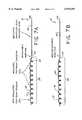
- FIG. 5is an idealized diagram showing the placement of a catheter utilzing on of the embodiments of the invention within a vascular aneurysm.
- FIG. 6.is a diagrammatic view of another embodiment of the invention showing utilization for cancer treatment.
- FIG. 7ais a simplified cross sectional side view of an embodiment for use in a second technique in which the invention may be practiced.
- FIG. 7bis a simplified side view of a catheter tip illustrated in a second embodiment also used in the second technique of the invention.
- FIG. 8is a simplified diagrammatic view which shows a source having a DC generator and an AC or RF generator coupled through a single pole, double throw switch to the delivery wire.
- a clotis generated in an aneurysm, arteriovenous malformation or fistula by means of a catheter having an insulated heating coil coupled to an insulated delivery wire.
- two delivery wiresare coupled to heating coils to provide a closed circuit.
- the heating coilsmay be in the form of a double helix or a single helix in combination with a straight heating coil.
- the heating coilsmay be permanently connected to the delivery wires or may be electrolytically or mechanically detached therefrom.
- a single insulated heating coilmay be attached to a single insulated delivery wire with an uninsulated coil attached to the tip of the insulated heating coil.
- the electrical circuitis then made through the heating coil and non-insulated electrode coil into the vascular system and to a body electrode.
- a cathetermay also be used for heating blood within the vascular system which is directly flowed into a tumoral mass for the purposes of thermal treatment of cancer.
- FIGS. 1-6which use some form of a double wire or closed circuit loop
- FIGS. 7a and 7bwhich uses some form of a single wire or body circuit loop
- the inventionmay be practiced using a plurality of different embodiments or modifications.
- the catheter tips of the methodology of the inventioncan be further be used not only for the promotion of clotting in aneurysms, arteriovenous malformations of fistulas, but also in therapeutic treatment of tumoral cells.
- FIG. 1a catheter, generally denoted by reference numeral 10, is provided with two insulated stainless steel delivery wires 12 and 14 covered by insulating jackets 16. Additional catheter elements as are now known or later developed in the art may be included in the actual structure of the catheter, which is used. Delivery wires 12 and 14 are shown in isolation of the catheter assembly per se inasmuch as the remaining catheter structure is conventional and largely immaterial to the operation of the invention. However, it must be clearly understood that the delivery wires 12 and 14 are not necessarily disposed in the vascular system as a pair of associated wires as the simplified diagrammatic side views of FIGS. 1-4 might suggest. Instead, wires 12 and 14 would be appropriately included within a delivery or guide catheter of conventional design, which is symbolically denoted in FIG. 5 by reference numeral 22. Wires 12 and 14 could be coaxial.
- Delivery wire 12terminates at an end 18 of its insulating jacket 16 and is coupled at or near end 18 to a Teflon insulated platinum helix 20.
- the diameter of platinum helix 20is typically in the range of 0.1 to 0.5 millimeters and may be comprised of a tight helical platinum wire, which when extended from the end of delivery catheter 22 as shown in FIG. 5, forms itself into a helical envelope as depicted by the large helical form in FIGS. 1-4.
- stainless steel delivery wire 14terminates at its end 24 by connection to a Teflon insulated platinum helical coil 26 which, when released, also extends in the embodiment of FIG. 1 as a helix.
- Coils 20 and 26thus form a pair of helical coils similar in gross geometry to the double helical coil of a DNA molecule.
- Helical coils 20 and 26are coupled together at their distal ends 30, or may be fabricated from a single integral strand of coil, which is then bent or turned at end 30.
- connection between delivery wires 12 and 14 and helical coils 20 and 26, respectively, in the embodiment of FIG. 1is by means of a permanent solder joint, although other types of mechanical and electrical connections are contemplated, some of which are described in the embodiments of FIGS. 2-4.
- platinum coils 20 and 26may be entirely or substantially limp, or without defined or prebiased form, so that a loose bird nest's configuration is formed by the released coils 20 and 26 as opposed to the tendency to form DNA-like double helix coil structures as shown in the embodiment of FIG. 1.
- coils 20 and 26may or may not retain some type of geometric association with each other after being disposed out of the end of catheter 22 depending on the embodiment utilized.
- the electrical resistance of platinum or the platinum tungsten alloy from which coils 20 and 26 are fabricatedis typically much higher than that of the stainless steel delivery wires which comprise wires 12 and 14. Therefore, it is possible to apply an electrical current to the double helical tip 28, which is comprised of coils 20 and 26, to selectively cause tip 28 to thermally heat with substantially no heat produced in delivery wires 12 and 14, because of the large disparity in the resistance between the two.
- the electrical current applied to coil tip 28 through delivery wires 12 and 14may be a DC current, alternating current, a radiofrequency power signal or any combination of the same. Regardless of the frequency of the electrical current, the current signal may have any envelope desired or be modulated in any way desired including modulation in the form of sin waves, square waves, triangular waves, pulsed, continuous or the like.
- Coils 20 and 26are Teflon coated or provided with another biologically nontoxic insulating material to prevent electrical shorting between coils 20 and 26 at any point.
- the solder connections in the embodiment of FIG. 1 between delivery wires 12 and 14 and coils 20 and 26, respectively,may similarly be insulated or laced at different longitudinal positions with respect to ends 18 and 24 of insulation 16 in order to avoid or to assist in avoiding short circuits between the solder connections.
- FIG. 2illustrates catheter 10 again in simplified side view and is identical in all respects to the embodiment of FIG. 1 with the exception that coil 26 has been replaced by a Teflon coated straight platinum wire 32.
- wire 32is shown in FIG. 2 as straight, it must be understood that wire 32 typically has a diameter of 0.025 to 0.25 millimeters and can, in fact, be quite flexible and limp.
- the stiffness of wire 32 both by its solid geometric cross section, as well as by choice of the platinum-tungsten alloycan be chosen to have a variety of different stiffnesses as may be desired in order to provide a degree of steerability of tip 28, controlled flexibility or malleability for disposition into the target body cavity.
- a third embodiment of catheter 10is illustrated in the simplified side view of FIG. 3.
- catheter 10 of FIG. 3is identical in all respects to the embodiment of FIG. 1 with the exception that coils 20 and 26 are connected to delivery wires 12 and 14 by means of corresponding temporary or detachable junctions 34.
- Tip 28is preferably electrolytically detachable by applying a DC current between delivery wires 12 and 14 and a ground electrode 54, typically applied to an exterior body site and catheter 10 is disposed within the vascular system of a patient as shown in FIG. 5. The detailed nature of the electrolytic detachment of tip 28 as shown in FIG.
- Tip 28is separated from wires 12 and 14 by electrolytic dissolution of junctions 34.
- Junctions 34which are offset from each other to avoid contact with each other, are uninsulated and thus exposed to the blood stream so that they may be electrolytically corroded away at the defined location of the junction and coils 20 and 26 separated from delivery wires 12 and 14. Delivery wires 12 and 14 are thereafter removed, leaving tip 28 embedded in the thrombus thermally formed within the vascular cavity.
- Catheter 10 of the embodiment of FIG. 4is substantially identical to the embodiment of FIG. 2 with the exception that coils 20 and 32 are coupled to delivery wires 12 and 14, respectively, through temporary junctions 34 of the type described in connection with the embodiment of FIG. 3.
- FIGS. 14are employed in the vascular system of a patient as diagrammatically depicted in FIG. 5.
- the proximal end of delivery wires 12 and 14are coupled to a signal or power source, generally denoted by reference numeral 36.
- source 36is diagrammatically shown as symbolically including the double pole, double throw switch 38 for selectively coupling either a DC generator 40 or an AC or RF generator 42 to delivery wires 12 and 14.
- Switch 38may be of anymore including a solid state switch.
- Source 36is a conventional power source and may provide a current for the electrolytic detachment, electrolytic formation of thrombus, and/or thermal formation of thrombi utilizing conventional circuitry or such circuits later devised. As a consequence, further details concerning source 36 will not be discussed.
- Catheter 10is endovascularly disposed within the patient's vascular system using conventional medical techniques.
- Tip 28is disposed in a vascular aneurysm, arteriovenous malformation or fistula, symbolically denoted by reference numeral 44, and illustrated in the embodiment of FIG. 5 as a wide-necked aneurysm 44 having an aneurysm opening or neck approximately 4 millimeters or greater.
- the apparatus and methodology of the inventionis useful without limitation in aneurysms, malformations and fistulas without limitation, but is shown in connection with a wide-necked aneurysm 44 as being used to particular advantage.
- Catheter 10is disposed through vessel 48 into neck 46 to form a hairball or bird nest of coils comprising tip 28.
- Tip 28is substantially proportionally longer then what is suggested in the simplified depictions of FIGS. 1-4, which, for the sake of simplicity, show tip 28 in a shortened form or at least in a much enlarged scale compared to that of FIG. 5.
- tip 28is 40 mm to 300 long while delivery wires 12 and 14 with microcatheter 22 may be 1000 to 1500 mm long.
- Coil tip 28is thus delivered into aneurysm 44 by use of microcatheter 22 which is then withdrawn from aneurysm 44 into front vessel 48 providing the configuration as illustrated in FIG. 5.
- junctions 34are disposed in or near aneurysm 44 or its neck 46. Junction 34 is easily detected through fluoroscopy techniques due to the greater radio-opacity of platinum as opposed to stainless steel.
- a second microcatheter 50is then disposed into vessel 48 which carries a detachable balloon 52.
- Balloon 52is positioned next to neck 46 of aneurysm 48 and temporarily inflated in front vessel 48 to substantially seal across aneurysm neck 46 as depicted in the configuration of FIG. 5 or at least to substantial reduce or stop the blood flow past neck 46.
- Balloon 52halts the flow of blood allowing the heat that is generated within aneurysm 44, when coil tip 28 is electrically heated, to be trapped within aneurysm 44. In many, if not most, instances, if no blood flow arrest were provided in vessel 48, the heat would be carried away by the blood flow and the formation of the thrombus substantially impeded.
- balloon 52is unnecessary. It is anticipated that in other applications, such as narrow necked aneurysms or appropriately shaped vasculated fistulas or malformations, the use of balloon 52 may not be necessary.
- An alternating electric currenttypically in the range of 20-40 volts at 40-60 milliamps, is then applied to the proximal ends of delivery wires 12 and 14 through switch 38 from source 36.
- Platinum tip 28 disposed within aneurysm 44becomes heated and in turn heats the blood within aneurysm 44 to achieve an intra-aneurysmal thrombosis.
- Various ways of monitoring the intra-aneurysmal temperaturecan be utilized and incorporated into the design of coil tip 28.
- the resistance of the platinum tungsten alloyis a function of its temperature which may be monitored by appropriate conventional resistance detector within source 36. Thermal energy dosages can be determined by temperature and time measurements.
- delivery wires 12 and 14are then coupled by means of switch 38 to DC generator 40.
- direct current of 1 milliamp at 2.5 voltsis then applied from DC generator 40 through delivery wires 12 and 14 in parallel utilizing a body electrode 54 as the opposite DC electrode.
- Junctions 34thus become electrolytically dissolved so that the platinum tungsten tip 28 now embedded in the clotted aneurysm is detached from catheter 10.
- Catheter 10 and delivery wires 12 and 14are then pulled away with balloon 52 deflated and similarly removed.
- FIG. 6illustrates one such application used for therapeutic treatment of tumoral cells.
- coil tip 28 of catheter 10is endovascularly disposed within a vessel 56 which leads, for example, into a vasculated tumoral mass 58. Blood flows in vessel 56 in the direction indicated by arrow 60. AC or RF current is then applied to tip 10 providing a controlled degree of heating of blood 60 such that the heated blood is then delivered to tumoral mass 58.
- the blood delivered to mass 58may only be heated by 42 to 47 degrees centigrade to have therapeutic effect.
- the temperature elevationis sufficient for many types of cancers to destroy the tumoral cells.
- the tumoral cellsmay be tagged or treated to specifically absorb a thermally activated agent that will assist in the destruction of the cell, such as by a thermal cyanin acting in a manner similar to photocyanins.
- synergistic treatment of tumoral mass 58is contemplated by combining thermal treatment as described in FIG. 6 with simultaneous or sequential chemotherapy or radiation.
- FIGS. 7a and billustrate additional embodiments of catheter 10 utilized in the second technique of the invention.
- a single helical platinum-tungsten coil 62 having a Teflon or other insulating coating thereonis temporarily coupled by means of a detachable junction 64 to a single stainless steel delivery wire 66, which is disposed within an insulated jacket 68.
- insulated wire 66may be disposed within a delivery microcatheter or other catheter assembly as is conventionally used.
- the distal end 70 of the insulated platinum-tungsten coil 62is permanently connected, such as by soldering, to an uninsulated platinum-iridium coil 72.
- Coil 72is typically shorter in length than coil 62.
- Coil 72serves as an electrode for contact with the blood or body tissue for completion of the circuit to a body electrode 54.
- Platinum-tungsten coil 62typically has a substantially higher electrical resistance than either platinum iridium coil 72 or stainless steel wire 66, so that substantially all the heating is in coil 62.
- FIG. 7bThe embodiment of FIG. 7b is identical to that described in connection with FIG. 7a with the exception that temporary detachable junction 64 is replaced by permanent or soldered junction 74.
- FIG. 8is a simplified diagrammatic view which again shows a source 36 having a DC generator 40 and an AC or RF generator 42 coupled through a single pole, double throw switch 76 to delivery wire 66.
- AC or RF generator 42has its opposing electrode coupled to body electrode 54.
- Coil tip 28is comprised in the embodiments of FIGS. 7a and 7b of coil tip portions 62 and 72 and is disposed by means of microcatheter 22 into vessel 78 and then coupled by means of switch 76 to generator 42. The current is then applied to delivery wire 66 and current flows to coil tip 28 and thence to uninsulated platinum iridium coil 72, which is the only portion of tip 28 in electrical contact with the blood or body fluids. The only portion of current tip 28 which heats to any substantial extent is the platinum tungsten portion, coil 62, because of its relative high electrical resistance.
- catheter 10is used to occlude an aneurysm, then coil 62 and 72 of tip 28 are then both exposed within the aneurysm and electrolytically detached utilizing the embodiment of FIG. 7a.
- catheter 10is used to heat the blood, such as for tumoral treatment as shown in FIG. 6, then the embodiment of FIG. 7b is preferably used.
Landscapes
- Health & Medical Sciences (AREA)
- Life Sciences & Earth Sciences (AREA)
- Surgery (AREA)
- Engineering & Computer Science (AREA)
- Animal Behavior & Ethology (AREA)
- Biomedical Technology (AREA)
- Heart & Thoracic Surgery (AREA)
- General Health & Medical Sciences (AREA)
- Public Health (AREA)
- Veterinary Medicine (AREA)
- Medical Informatics (AREA)
- Nuclear Medicine, Radiotherapy & Molecular Imaging (AREA)
- Molecular Biology (AREA)
- Vascular Medicine (AREA)
- Reproductive Health (AREA)
- Plasma & Fusion (AREA)
- Otolaryngology (AREA)
- Physics & Mathematics (AREA)
- Cardiology (AREA)
- Neurosurgery (AREA)
- Biophysics (AREA)
- Pulmonology (AREA)
- Anesthesiology (AREA)
- Hematology (AREA)
- Surgical Instruments (AREA)
- Medicines Containing Plant Substances (AREA)
- Radiation-Therapy Devices (AREA)
- Prostheses (AREA)
- Ultra Sonic Daignosis Equipment (AREA)
- Electrotherapy Devices (AREA)
- Thermotherapy And Cooling Therapy Devices (AREA)
Abstract
Description
The present application is a divisional application of of U.S. patent application Ser. No. 08/497,294 filed Jun. 30, 1995 now U.S. Pat. No. 5,851,206, which in turn is a continuation-in-part application of U.S. patent application Ser. No. 08/311,508 filed Sep. 23, 1994, now U.S. Pat. No. 5,540,680, and entitled "Improvements in an Endovascular Electrolytically Detachable Wire and Tip for the Formation of Thrombus in Arteries, Veins, Aneurysms, Vascular Malformations, and Arteriouvenous Fistulas", which was a continuation-in-part application of application Ser. No. 08/840,211, filed Feb. 24, 1992, and issued as U.S. Pat. No. 5,354,295, which in turn was a continuation-in-part application of application Ser. 07/492,717, filed Mar. 13, 1990 and issued as U.S. Pat. No. 5,122,136, all of which are incorporated herein by reference as if set forth in their entirety.
1. Field of the Invention
The invention relates to the field of endovascular devices and methodologies and in particular to a means for endovascular heating of blood for purposes of promoting thrombosis in aneurysms, thrombosis in arteriovenous malformations or fistulas, and thermally heating blood in a tumor for consequent destruction of tumoral cells.
2. Description of the Prior Art
Approximately 25,000 intracranial aneurysms rupture every year in North America. The primary purpose of treatment for ruptured intracranial aneurysm is to prevent rebleeding. At the present time, three general methods of treatment exist, namely an extravascular, endovascular and extra-endovascular approach.
The extravascular approach is comprised of surgery or microsurgery of the aneurysm or treatment site for the purpose of preserving the parent artery. This treatment is common with intracranial berry aneurysms. The methodology comprises the step of clipping the neck of the aneurysm, performing a suture-ligation of the neck, or wrapping the entire aneurysm. Each of these surgical procedures is performed by intrusive invasion into the body and performed from outside the aneurysm or target site. General anesthesia, craniotomy, brain retraction and arachnoid dissection around the neck of the aneurysm and placement of a clip are typically required in these surgical procedures. Surgical treatment of vascular intracranial aneurysm can expect a mortality rate of 4-8% with a morbidity rate of 18-20%. Because of the mortality and morbidity rate expected, the surgical procedure is often delayed while waiting for the best surgical time with the result that an additional percentage of patients will die from the underlying disease or defect prior to surgery. For this reason the prior art has sought alternative means of treatment.
In the endovascular approach, the interior of the aneurysm is entered through the use of a microcatheter. Recently developed microcatheters, such as those shown by Engleson, "Catheter Guidewire" U.S. Pat. No. 4,884,579 and as described in Engleson, "Catheter for Guidewire Tracking", U.S. Pat. No. 4,739,768 (1988), allow navigation into the cerebral arteries and entry into a cranial aneurysm.
In such procedures a balloon is typically attached to the end of the microcatheter and it is possible to introduce the balloon into the aneurysm, inflate it, and detach it, leaving it to occlude the sac and neck with preservation of the parent artery. While endovascular balloon embolization of berry aneurysms is an attractive method in situations where an extravascular surgical approach is difficult, inflation of a balloon into the aneurysm carries some risk of aneurysm rupture due to possible over-distention of portions of the sac and due to the traction produced while detaching the balloon.
While remedial procedures exist for treating a ruptured aneurysm during classical extravascular surgery, no satisfactory methodology exists if the aneurysm breaks during an endovascular balloon embolization.
Furthermore, an ideal embolizing agent should adapt itself to the irregular shape of the internal walls of the aneurysm. On the contrary, in a balloon embolization the aneurysmal wall must conform to the shape of the balloon. This may not lead to a satisfactory result and further increases the risk of rupture.
Still further, balloon embolization is not always possible. If the diameter of the deflated balloon is too great to enter the intracerebral arteries, especially in the cases where there is a vasospasm, complications with ruptured intracranial aneurysms may occur. The procedure then must be deferred until the spasm is resolved and this then incurs a risk of rebleeding.
In the extra-intravascular approach, an aneurysm is surgically exposed or stereotaxically reached with a probe. The wall of the aneurysm is then perforated from the outside and various techniques are used to occlude the interior in order to prevent it from rebleeding. These prior art techniques include electrothrombosis, isobutyl-cyanoacrylate embolization, hog-hair embolization and ferromagnetic thrombosis.
In the use of electrothrombosis for extra-intravascular treatment the tip of a positively charged electrode is inserted surgically into the interior of the aneurysm. An application of the positive charge attracts white blood cells, red blood cells, platelets and fibrinogen which are typically negatively charged at the normal pH of the blood. The thrombic mass is then formed in the aneurysm about the tip. Thereafter, the tip is removed. See Mullan, "Experiences with Surgical Thrombosis of Intracranial Berry Aneurysms and Carotid Cavernous Fistulas", J. Neurosurg., Vol. 41, December 1974; Hosobuchi, "Electrothrombosis Carotid-Cavernous Fistula", J. Neurosurg., Vol. 42, January 1975; Araki et al., "Electrically Induced Thrombosis for the Treatment of Intracranial Aneurysms and Angiomas", Excerpta Medica International Congress Series, Amsterdam 1965, Vol. 110, 651-654; Sawyer et al., "Bio-Electric Phenomena as an Etiological Factor in Intravascular Thrombosis", Am. J. Physiol., Vol. 175, 103-107 (1953); J. Piton et al., "Selective Vascular Thrombosis Induced by a Direct Electrical Current; Animal Experiments", J. Neuroradiology, Vol. 5, pages 139-152 (1978). However, each of these techniques involves some type of intrusive procedure to approach the aneurysm from the exterior of the body.
The prior art has also devised the use of a liquid adhesive, isobutyl-cyanoacrylate (IBCA) which polymerizes rapidly on contact with blood to form a firm mass. The liquid adhesive is injected into the aneurysm by puncturing the sac with a small needle. In order to avoid spillage into the parent artery during IBCA injection, blood flow through the parent artery must be momentarily reduced or interrupted. Alternatively, an inflated balloon may be placed in the artery at the level of the neck of the aneurysm for injection. In addition to the risks caused by temporary blockage of the parent artery, the risks of seepage of such a polymerizing adhesive into the parent artery exists, if it is not completely blocked with consequent occlusion of the artery.
Still further, the prior art has utilized an air gun to inject hog hair through the aneurysm wall to induce internal thrombosis. The success of this procedure involves exposing the aneurysm sufficiently to allow air gun injection and has not been convincingly shown as successful for thrombic formations.
Ferromagnetic thrombosis in the prior art in extra-intravascular treatments comprises the stereotactic placement of a magnetic probe against the sac of the aneurysm followed by injection into the aneurysm by an injecting needle of iron microspheres. Aggregation of the microspheres through the extravascular magnet is followed by interneuysmatic thrombus. This treatment has not been entirely successful because of the risk of fragmentation of the metallic thrombus when the extravascular magnet is removed. Suspension of the iron powder in methyl methylmethacrylate has been used to prevent fragmentation. The treatment has not been favored, because of the need to puncture the aneurysm, the risk of occlusion of the parent artery, the use of unusual and expensive equipment, the need for a craniectomy and general anesthesia, and the necessity to penetrate cerebral tissue to reach the aneurysm.
Endovascular coagulation of blood is also well known in the art and a device using laser optically generated heat is shown by O'Reilly, "Optical Fiber with Attachable Metallic Tip for Intravascular Laser Coagulation of Arteries, Veins, Aneurysms, Vascular Malformation and Arteriovenous Fistulas", U.S. Pat. No. 4,735,201 (1988). See also, O'Reilly et al., "Laser Induced Thermal Occusion of Berry Aneurysms: Initial Experimental Results", Radiology, Vol. 171, No. 2, pages 471-74 (1989). O'Reilly places a tip into an aneurysm by means of an endovascular microcatheter. The tip is adhesively bonded to a optic fiber disposed through the microcatheter. Optical energy is transmitted along the optic fiber from a remote laser at the proximal end of the microcatheter. The optical energy heats the tip to cauterize the tissue surrounding the neck of the aneurysm or other vascular opening to be occluded. The catheter is provided with a balloon located on or adjacent to its distal end to cut off blood flow to the site to be cauterized and occluded. Normally, the blood flow would carry away the heat at the catheter tip, thereby preventing cauterization. The heat in the tip also serves to melt the adhesive used to secure the tip to the distal end of the optical fiber. If all goes well, the tip can be separated from the optical fiber and left in place in the neck of the aneurysm, provided that the cauterization is complete at the same time as the hot melt adhesive melts.
A thrombus is not formed from the heated tip. Instead, blood tissue surrounding the tip is coagulated. Coagulation is a denaturation of protein to form a connective-like tissue similar to that which occurs when the albumen of an egg is heated and coagulates from a clear running liquid to an opaque white solid. The tissue characteristics and composition of the coagulated tissue is therefore substantially distinct from the thrombosis which is formed by the thrombotic aggregation of white and red blood cells, platelets and fibrinogen. The coagulative tissue is substantially softer than a thrombic mass and can therefore more easily be dislodged.
O'Reilly's device depends at least in part upon the successful cauterization timed to occur no later than the detachment of the heat tip from the optic fiber. The heated tip must also be proportionally sized to the neck of the aneurysm in order to effectively coagulate the tissue surrounding it to form a blockage at the neck. It is believed that the tissue in the interior of the aneurysm remains substantially uncoagulated. In addition, the hot melt adhesive attaching the tip to the optic fiber melts and is dispersed into the adjacent blood tissue where it resolidifies to form free particles within the intracranial blood stream with much the same disadvantages which result from fragmentation of a ferromagnetic electrothrombosis.
Therefore, what is needed is an apparatus and methodology which avoids each of the shortcomings and limitations of the prior art discussed above.
The invention is an improvement in a catheter for use within a vascular system. The improvement comprises at least one delivery wire. At least one heating coil is coupled to the delivery wire. The delivery wire and heating coil are both electrically insulated to permit endovascular disposition of the delivery wire and heating coil into the vascular system for the purpose of delivering heat to a fluid within the vascular system at a predetermined location. Substantially all of the heat is generated by electrical current flowing within the heating coil rather than within the delivery wire, because of the greater electrical resistance of the heating coil. As a result, endovascular thermal treatment is provided within the vascular system.
The delivery wire and heating coil are temporarily coupled to each other and can be selectively detached. In the preferred embodiment the delivery wire and heating coil are electrolytically detachable from each other. However, the delivery wire and heating coil may also be mechanically detachable from each other.
The improvement further comprises at least two delivery wires and at least two heating coils, each having a proximal and distal end. The proximal end of each of the heating coils is coupled to corresponding ones of the two delivery wires. The distal end of the two heating coils is coupled together to provide a continuous circuit through a first one of the two delivery wires to a first one of the two heating coils, to a second one of the two heating coils, and to a second one of the two delivery wires.
In the illustrated embodiment the two heating coils are each helical and together form a double helical tip. In another embodiment one of the two delivery wires is helical and the other one of the two delivery wires is nonhelical.
In another embodiment the improvement further comprises a body electrode in electrical circuit with the vascular system. The heating coil has a proximal and distal end. The proximal end is coupled to the delivery wire and further comprises an uninsulated coil coupled to the distal end of the heating coil. The electrical resistance of the uninsulated coil is less than the heating coil so that substantially all of the heat generated by the current is generated within the insulated heating coil. The uninsulated coil serves as an endovascular electrode to provide completion of circuit through the delivery wire, and heating coil to the body electrode.
The improvement further comprises a current source coupled to the delivery wire for controllably delivering the electrical current thereto.
The invention is further defined as a method for forming coagulation of blood at a predetermined location within a vascular system. The method comprises the steps of disposing a microcatheter within the vascular system at the predetermined location and disposing from the microcatheter at the predetermined location at least one insulated heating coil. The insulated heating coil is electrically coupled to an insulated delivery wire included within the microcatheter and extends exteriorly to the vascular system. An electrical current is applied through the delivery wire to the heating coil to heat fluid within the vascular system at the predetermined location to thermally form a thrombus thereat. * As a result, thermal formation of a thrombus within the vascular system is selectively formed.
In the illustrated method at least two insulated heating coils connected together in an electrical circuit are disposed in the vascular system. Application of the current to the delivery wire and heating coil resistively generates substantially only within the heating coil.
In one embodiment the method further comprises applying current through the insulated heating coil to an uninsulated coil tip in electrical contact with the fluid in the vascular system to complete an electrical circuit through the delivery wire, heating coil and coil tip electrode to a body electrode in electrical communication with the vascular system.
The invention is still further characterized as a method for treating cancer comprising the steps of disposing a microcatheter within the vascular system at the predetermined location in a blood flow to a tumoral mass. At least one insulated heating coil is disposed from at by the microcatheter at the predetermined location. The insulated heating coil is electrically coupled to an insulated delivery wire included within the microcatheter and extends exteriorly to the vascular system. An electrical current is applied through the delivery wire to the heating coil to heat the blood flow within the vascular system at the predetermined location to thermally stress the tumoral mass downstream. As a result, thermal treatment of the tumoral mass is effected.
The invention and its various embodiments may be better visualized by turning to the following drawings wherein like elements are referenced by like numerals.
FIG. 1 is a simplified diagrammatic side view of a catheter tip embodying the present invention.
FIG. 2 is a simplified diagrammatic side view of a second embodiment of the invention.
FIG. 3 is a simplified diagrammatic side view of a third embodiment of the invention.
FIG. 4 is a simplified view of a fourth embodiment of the invention.
FIG. 5 is an idealized diagram showing the placement of a catheter utilzing on of the embodiments of the invention within a vascular aneurysm.
FIG. 6. is a diagrammatic view of another embodiment of the invention showing utilization for cancer treatment.
FIG. 7a is a simplified cross sectional side view of an embodiment for use in a second technique in which the invention may be practiced.
FIG. 7b is a simplified side view of a catheter tip illustrated in a second embodiment also used in the second technique of the invention.
FIG. 8 is a simplified diagrammatic view which shows a source having a DC generator and an AC or RF generator coupled through a single pole, double throw switch to the delivery wire.
The invention and its various embodiments may now be understood by turning to the following detailed description.
A clot is generated in an aneurysm, arteriovenous malformation or fistula by means of a catheter having an insulated heating coil coupled to an insulated delivery wire. In one embodiment, two delivery wires are coupled to heating coils to provide a closed circuit. The heating coils may be in the form of a double helix or a single helix in combination with a straight heating coil. The heating coils may be permanently connected to the delivery wires or may be electrolytically or mechanically detached therefrom.
Alternatively, a single insulated heating coil may be attached to a single insulated delivery wire with an uninsulated coil attached to the tip of the insulated heating coil. The electrical circuit is then made through the heating coil and non-insulated electrode coil into the vascular system and to a body electrode.
A catheter may also be used for heating blood within the vascular system which is directly flowed into a tumoral mass for the purposes of thermal treatment of cancer.
There are two main ways in which the goal of thermal thrombosis can be achieved in the invention, the first of which is illustrated in connection with FIGS. 1-6, which use some form of a double wire or closed circuit loop, and the second of which is illustrated in connection with the catheter tips shown in FIGS. 7a and 7b which uses some form of a single wire or body circuit loop.
Within each of these techniques, the invention may be practiced using a plurality of different embodiments or modifications. Further, the catheter tips of the methodology of the invention can be further be used not only for the promotion of clotting in aneurysms, arteriovenous malformations of fistulas, but also in therapeutic treatment of tumoral cells.
Consider first the first technique of endovascular promotion of the formation of clots as illustrated in FIGS. 1-5. As shown in FIG. 1, a catheter, generally denoted byreference numeral 10, is provided with two insulated stainlesssteel delivery wires jackets 16. Additional catheter elements as are now known or later developed in the art may be included in the actual structure of the catheter, which is used.Delivery wires delivery wires wires reference numeral 22.Wires
Similarly, stainlesssteel delivery wire 14 terminates at itsend 24 by connection to a Teflon insulated platinumhelical coil 26 which, when released, also extends in the embodiment of FIG. 1 as a helix.Coils distal ends 30, or may be fabricated from a single integral strand of coil, which is then bent or turned atend 30.
The connection betweendelivery wires helical coils
Further, in addition to generally forming a helical envelope as shown in FIG. 1, platinum coils 20 and 26 may be entirely or substantially limp, or without defined or prebiased form, so that a loose bird nest's configuration is formed by the released coils 20 and 26 as opposed to the tendency to form DNA-like double helix coil structures as shown in the embodiment of FIG. 1. In other words, coils 20 and 26 may or may not retain some type of geometric association with each other after being disposed out of the end ofcatheter 22 depending on the embodiment utilized.
The electrical resistance of platinum or the platinum tungsten alloy from which coils 20 and 26 are fabricated is typically much higher than that of the stainless steel delivery wires which comprisewires helical tip 28, which is comprised ofcoils tip 28 to thermally heat with substantially no heat produced indelivery wires
The electrical current applied tocoil tip 28 throughdelivery wires
The embodiment of FIG. 2 illustratescatheter 10 again in simplified side view and is identical in all respects to the embodiment of FIG. 1 with the exception thatcoil 26 has been replaced by a Teflon coatedstraight platinum wire 32. Althoughwire 32 is shown in FIG. 2 as straight, it must be understood thatwire 32 typically has a diameter of 0.025 to 0.25 millimeters and can, in fact, be quite flexible and limp. On the other hand, the stiffness ofwire 32 both by its solid geometric cross section, as well as by choice of the platinum-tungsten alloy, can be chosen to have a variety of different stiffnesses as may be desired in order to provide a degree of steerability oftip 28, controlled flexibility or malleability for disposition into the target body cavity.
A third embodiment ofcatheter 10 is illustrated in the simplified side view of FIG. 3. Again,catheter 10 of FIG. 3 is identical in all respects to the embodiment of FIG. 1 with the exception that coils 20 and 26 are connected todelivery wires detachable junctions 34.Tip 28 is preferably electrolytically detachable by applying a DC current betweendelivery wires ground electrode 54, typically applied to an exterior body site andcatheter 10 is disposed within the vascular system of a patient as shown in FIG. 5. The detailed nature of the electrolytic detachment oftip 28 as shown in FIG. 3 is described in greater detail in Guglielmi et al., "Endovascular Electroytically Detachable Guidewire Tip for the Electroformation of Thrombus in Arteries, Veins, Aneurysms, Vascular Malformations and Arteriovenous Fistulas," U.S. Pat. No. 5,122,136 (1992), incorporated herein by reference. Alternative means of both electrical and mechanical detachment are contemplated within the invention and are further described in U.S. Pat. No. 5,122,136 (1992) and U.S. Pat. No. 5,354,295 (1994) each of which are similarly incorporated by reference.
Another embodiment is depicted in the side view of FIG. 4.Catheter 10 of the embodiment of FIG. 4 is substantially identical to the embodiment of FIG. 2 with the exception that coils 20 and 32 are coupled todelivery wires temporary junctions 34 of the type described in connection with the embodiment of FIG. 3.
The embodiments of FIGS. 14 are employed in the vascular system of a patient as diagrammatically depicted in FIG. 5. The proximal end ofdelivery wires reference numeral 36. In the illustrated embodiment of FIG. 5,source 36 is diagrammatically shown as symbolically including the double pole,double throw switch 38 for selectively coupling either aDC generator 40 or an AC orRF generator 42 todelivery wires Switch 38 may be of anymore including a solid state switch.Source 36 is a conventional power source and may provide a current for the electrolytic detachment, electrolytic formation of thrombus, and/or thermal formation of thrombi utilizing conventional circuitry or such circuits later devised. As a consequence, furtherdetails concerning source 36 will not be discussed.
Asecond microcatheter 50 is then disposed intovessel 48 which carries adetachable balloon 52.Balloon 52 is positioned next toneck 46 ofaneurysm 48 and temporarily inflated infront vessel 48 to substantially seal acrossaneurysm neck 46 as depicted in the configuration of FIG. 5 or at least to substantial reduce or stop the blood flow pastneck 46.Balloon 52 halts the flow of blood allowing the heat that is generated withinaneurysm 44, whencoil tip 28 is electrically heated, to be trapped withinaneurysm 44. In many, if not most, instances, if no blood flow arrest were provided invessel 48, the heat would be carried away by the blood flow and the formation of the thrombus substantially impeded. However, this is not always the case, and in some applications the use ofballoon 52 is unnecessary. It is anticipated that in other applications, such as narrow necked aneurysms or appropriately shaped vasculated fistulas or malformations, the use ofballoon 52 may not be necessary.
An alternating electric current, typically in the range of 20-40 volts at 40-60 milliamps, is then applied to the proximal ends ofdelivery wires switch 38 fromsource 36.Platinum tip 28 disposed withinaneurysm 44 becomes heated and in turn heats the blood withinaneurysm 44 to achieve an intra-aneurysmal thrombosis. Various ways of monitoring the intra-aneurysmal temperature can be utilized and incorporated into the design ofcoil tip 28. For example, the resistance of the platinum tungsten alloy is a function of its temperature which may be monitored by appropriate conventional resistance detector withinsource 36. Thermal energy dosages can be determined by temperature and time measurements.
Once thrombosis has been achieved,delivery wires switch 38 toDC generator 40. Typically, direct current of 1 milliamp at 2.5 volts is then applied fromDC generator 40 throughdelivery wires body electrode 54 as the opposite DC electrode.Junctions 34 thus become electrolytically dissolved so that theplatinum tungsten tip 28 now embedded in the clotted aneurysm is detached fromcatheter 10.Catheter 10 anddelivery wires balloon 52 deflated and similarly removed.
While the embodiments of FIGS. 3 and 4 are described as being used in a method for thrombus formation in FIG. 5, any of the embodiments of the invention and, in particular the embodiments of FIGS. 1 and 2, may be utilized in applications where endovascular blood heating is needed. FIG. 6 illustrates one such application used for therapeutic treatment of tumoral cells. In the embodiment of FIG. 6,coil tip 28 ofcatheter 10 is endovascularly disposed within avessel 56 which leads, for example, into a vasculatedtumoral mass 58. Blood flows invessel 56 in the direction indicated byarrow 60. AC or RF current is then applied to tip 10 providing a controlled degree of heating ofblood 60 such that the heated blood is then delivered totumoral mass 58. Typically, the blood delivered tomass 58 may only be heated by 42 to 47 degrees centigrade to have therapeutic effect. The temperature elevation is sufficient for many types of cancers to destroy the tumoral cells. It is further expressly contemplated that the tumoral cells may be tagged or treated to specifically absorb a thermally activated agent that will assist in the destruction of the cell, such as by a thermal cyanin acting in a manner similar to photocyanins. Further, synergistic treatment oftumoral mass 58 is contemplated by combining thermal treatment as described in FIG. 6 with simultaneous or sequential chemotherapy or radiation.
FIGS. 7a and b illustrate additional embodiments ofcatheter 10 utilized in the second technique of the invention. In the embodiment of FIG. 7a, a single helical platinum-tungsten coil 62 having a Teflon or other insulating coating thereon is temporarily coupled by means of adetachable junction 64 to a single stainlesssteel delivery wire 66, which is disposed within aninsulated jacket 68. Again,insulated wire 66 may be disposed within a delivery microcatheter or other catheter assembly as is conventionally used. Thedistal end 70 of the insulated platinum-tungsten coil 62 is permanently connected, such as by soldering, to an uninsulated platinum-iridium coil 72.Coil 72 is typically shorter in length thancoil 62.Coil 72 serves as an electrode for contact with the blood or body tissue for completion of the circuit to abody electrode 54. Platinum-tungsten coil 62 typically has a substantially higher electrical resistance than eitherplatinum iridium coil 72 orstainless steel wire 66, so that substantially all the heating is incoil 62.
The embodiment of FIG. 7b is identical to that described in connection with FIG. 7a with the exception that temporarydetachable junction 64 is replaced by permanent or solderedjunction 74.
Ifcatheter 10 is used to occlude an aneurysm, thencoil tip 28 are then both exposed within the aneurysm and electrolytically detached utilizing the embodiment of FIG. 7a. However, ifcatheter 10 is used to heat the blood, such as for tumoral treatment as shown in FIG. 6, then the embodiment of FIG. 7b is preferably used.
Many alterations and modifications may be made by those having ordinary skill in the art without departing from the spirit and scope of the invention. Therefore, it must be understood that the illustrated embodiment has been set forth only for the purposes of example and that it should not be taken as limiting the invention as defined by the following claims.
The words used in this specification to describe the invention and its various embodiments are to be understood not only in the sense of their commonly defined meanings, but to include by special definition in this specification structure, material or acts beyond the scope of the commonly defined meanings. Thus if an element can be understood in the context of this specification as including more than one meaning, then its use in a claim must be understood as being generic to all possible meanings supported by the specification and by the word itself.
The definitions of the words or elements of the following claims are, therefore, defined in this specification to include not only the combination of elements which are literally set forth, but all equivalent structure; material or acts for performing substantially the same function in substantially the same way to obtain substantially the same result.
In addition to the equivalents of the claimed elements, obvious substitutions now or later known to one with ordinary skill in the art are defined to be within the scope of the defined elements.
The claims are thus to be understood to include what is specifically illustrated and described above, what is conceptionally equivalent, what can be obviously substituted and also what essentially incorporates the essential idea of the invention.
Claims (17)
1. An improvement in an endovascular device for use within a vascular system comprising:
at least one elongate, flexible, fully insulated and substantially unsupported delivery wire having a first resistance; and
at least one elongate, flexible, fully insulated, substantially unsupported, and longitudinally resilient heating coil having a second resistance coupled to said delivery wire, said first resistance being less than said second resistance, wherein said delivery wire and heating coil are both electrically insulated to permit endovascular disposition of said delivery wire and heating coil into said vascular system to deliver heat to blood within said vascular system at a predetermined location, substantially all of said heat being generated by electrical current flowing within said heating coil rather than within said delivery wire,
whereby endovascular thermal treatment is provided within said vascular system.
2. The improvement of claim 1 wherein said delivery wire and heating coil are permanently coupled to each other.
3. The improvement of claim 1 further comprising a body electrode in adapted to be in contact with a body having said vascular system and therefore in electrical circuit with said vascular system, and wherein said heating coil has a proximal and distal end, said proximal end being coupled to said delivery wire and further comprising a uninsulated coil coupled to said distal end of said heating coil, said uninsulated coil having an electrical resistance, said electrical resistance of said uninsulated coil being less than said heating coil so that substantially all of said heat generated by said current is generated within said heating coil, said uninsulated coil serving as an endovascular electrode to provide completion of circuit through said delivery wire, and heating coil to said body electrode.
4. The improvement of claim 3 wherein said delivery wire and heating coil are permanently coupled to each other.
5. The improvement of claim 1 further comprising a current source coupled to said delivery wire for controllably delivering said electrical current thereto.
6. An improvement in an endovascular device for use within a vascular system comprising:
at least one delivery wire having a first resistance;
at least one heating coil having a second resistance coupled to said delivery wire, said first resistance being less than said second resistance, wherein said delivery wire and heating coil are both electrically insulated to permit endovascular disposition of said delivery wire and heating coil into said vascular system to deliver heat to a fluid within said vascular system at a predetermined location, substantially all of said heat being generated by electrical current flowing within said heating coil rather than within said delivery wire; and
at least two delivery wires and at least two heating coils each having a proximal and distal end, said proximal end of each of said heating coils being coupled to corresponding ones of said two delivery wires, said distal end of said two heating coils being coupled together to provide a continuous circuit through a first one of said two delivery wires to a first one of said two heating coils, to a second one of said two heating coils, and to a second one of said two delivery wires,
whereby endovascular thermal treatment is provided within said vascular system.
7. The improvement of claim 6 wherein said two heating coils are each helical and together form a double helical tip.
8. The improvement of claim 7 wherein said delivery wire and heating coil are permanently coupled to each other.
9. The improvement of claim 6 wherein one of said two delivery wires is helical and the other one of said two delivery wires is nonhelical.
10. A method for selectively heating tissue at a predetermined location within a vascular system comprising:
disposing a microcatheter within said vascular system at said predetermined location;
disposing from said microcatheter at said predetermined location at least one insulated heating coil, said insulated heating coil being electrically coupled to an insulated delivery wire included within said microcatheter and extending exteriorly to said vascular system;
applying electrical current through said delivery wire to said heating coil to heat blood within said vascular system at said predetermined location to thermally heat tissue in contact with said blood; and
withdrawing said microcatheter and delivery wire from said vascular system,
whereby thermal heating of tissue within said vascular system is selectively formed.
11. The method of claim 10 where disposing a heating coil in said vascular system comprises disposing at least two insulated heating coils connected together in an electrical circuit.
12. The method of claim 10 where applying said current to said delivery wire and heating coil resistively generates heat substantially only within said heating coil.
13. The method of claim 10 where applying current to said delivery wire and heating coil further comprises applying current through said heating coil to an uninsulated coil tip in electrical contact with said blood in said vascular system to complete an electrical circuit through said delivery wire, heating coil and coil tip electrode to a body electrode in electrical communication with said vascular system.
14. A method for treating cancer comprising:
disposing a microcatheter within said vascular system at said predetermined location in a blood flow to a tumoral mass;
disposing from said microcatheter at said predetermined location at least one insulated heating coil, said insulated heating coil being electrically coupled to an insulated delivery wire included within said microcatheter and extending exteriorly to said vascular system; and
applying an electrical current through said delivery wire to said heating coil to heat said blood flow within said vascular system at said predetermined location to thermally stress said tumoral mass downstream,
whereby thermal treatment of said tumoral mass is effected.
15. The method of claim 14 where disposing said microcather comprises disposing at least two insulated heating coils connected together in an electrical circuit in said vascular system.
16. The method of claim 14 where applying said current to said delivery wire and heating coil resistively generates heat substantially only within said heating coil.
17. The method of claim 14 where applying current to said delivery wire and heating coil further comprises applying current through said heating coil to an uninsulated coil tip in electrical contact with said blood in said vascular system to complete an electrical circuit through said delivery wire, heating coil and coil tip electrode to a body electrode in electrical communication with said vascular system.
Priority Applications (1)
| Application Number | Priority Date | Filing Date | Title |
|---|---|---|---|
| US08/528,915US5919187A (en) | 1990-03-13 | 1995-09-15 | Method and apparatus for endovascular thermal thrombosis and thermal cancer treatment |
Applications Claiming Priority (5)
| Application Number | Priority Date | Filing Date | Title |
|---|---|---|---|
| US07/492,717US5122136A (en) | 1990-03-13 | 1990-03-13 | Endovascular electrolytically detachable guidewire tip for the electroformation of thrombus in arteries, veins, aneurysms, vascular malformations and arteriovenous fistulas |
| US07/840,211US5354295A (en) | 1990-03-13 | 1992-02-24 | In an endovascular electrolytically detachable wire and tip for the formation of thrombus in arteries, veins, aneurysms, vascular malformations and arteriovenous fistulas |
| US08/311,508US5540680A (en) | 1990-03-13 | 1994-09-23 | Endovascular electrolytically detachable wire and tip for the formation of thrombus in arteries, veins, aneurysms, vascular malformations and arteriovenous fistulas |
| US08/497,294US5851206A (en) | 1990-03-13 | 1995-06-30 | Method and apparatus for endovascular thermal thrombosis and thermal cancer treatment |
| US08/528,915US5919187A (en) | 1990-03-13 | 1995-09-15 | Method and apparatus for endovascular thermal thrombosis and thermal cancer treatment |
Related Parent Applications (1)
| Application Number | Title | Priority Date | Filing Date |
|---|---|---|---|
| US08/497,294DivisionUS5851206A (en) | 1990-03-13 | 1995-06-30 | Method and apparatus for endovascular thermal thrombosis and thermal cancer treatment |
Publications (1)
| Publication Number | Publication Date |
|---|---|
| US5919187Atrue US5919187A (en) | 1999-07-06 |
Family
ID=23976267
Family Applications (2)
| Application Number | Title | Priority Date | Filing Date |
|---|---|---|---|
| US08/497,294Expired - LifetimeUS5851206A (en) | 1990-03-13 | 1995-06-30 | Method and apparatus for endovascular thermal thrombosis and thermal cancer treatment |
| US08/528,915Expired - LifetimeUS5919187A (en) | 1990-03-13 | 1995-09-15 | Method and apparatus for endovascular thermal thrombosis and thermal cancer treatment |
Family Applications Before (1)
| Application Number | Title | Priority Date | Filing Date |
|---|---|---|---|
| US08/497,294Expired - LifetimeUS5851206A (en) | 1990-03-13 | 1995-06-30 | Method and apparatus for endovascular thermal thrombosis and thermal cancer treatment |
Country Status (12)
| Country | Link |
|---|---|
| US (2) | US5851206A (en) |
| EP (1) | EP0750886B1 (en) |
| JP (1) | JP3131386B2 (en) |
| KR (1) | KR100437847B1 (en) |
| AT (1) | ATE236583T1 (en) |
| AU (1) | AU723902B2 (en) |
| CA (1) | CA2179863C (en) |
| DE (1) | DE69627243T2 (en) |
| DK (1) | DK0750886T3 (en) |
| ES (1) | ES2196123T3 (en) |
| NO (1) | NO321938B1 (en) |
| TW (1) | TW396029B (en) |
Cited By (130)
| Publication number | Priority date | Publication date | Assignee | Title |
|---|---|---|---|---|
| US6077260A (en)* | 1998-02-19 | 2000-06-20 | Target Therapeutics, Inc. | Assembly containing an electrolytically severable joint for endovascular embolic devices |
| US6099546A (en)* | 1993-04-19 | 2000-08-08 | Target Therapeutics, Inc. | Detachable embolic coil assembly using interlocking hooks and slots |
| US6156061A (en)* | 1997-08-29 | 2000-12-05 | Target Therapeutics, Inc. | Fast-detaching electrically insulated implant |
| US6165178A (en)* | 1997-08-29 | 2000-12-26 | Scimed Life Systems, Inc. | Fast detaching electrically isolated implant |
| US6190373B1 (en) | 1992-11-13 | 2001-02-20 | Scimed Life Systems, Inc. | Axially detachable embolic coil assembly |
| US6238415B1 (en)* | 1994-12-22 | 2001-05-29 | Target Therapeutics, Inc | Implant delivery assembly with expandable coupling/decoupling mechanism |
| US6280441B1 (en)* | 1997-12-15 | 2001-08-28 | Sherwood Services Ag | Apparatus and method for RF lesioning |
| US6287318B1 (en) | 1998-02-13 | 2001-09-11 | Target Therapeutics, Inc. | Vaso-occlusive device with attached polymeric materials |
| US6371972B1 (en) | 1998-02-18 | 2002-04-16 | Target Therapeutics, Inc. | Vaso-occlusive member assembly with multiple detaching points |
| US6375654B1 (en)* | 2000-05-19 | 2002-04-23 | Cardiofocus, Inc. | Catheter system with working portion radially expandable upon rotation |
| US6397850B1 (en)* | 2000-02-09 | 2002-06-04 | Scimed Life Systems Inc | Dual-mode apparatus and method for detection of embolic device detachment |
| US6475227B2 (en) | 1997-12-24 | 2002-11-05 | Scimed Life Systems, Inc. | Vaso-occlusion apparatus having a mechanically expandable detachment joint and a method for using the apparatus |
| US6529775B2 (en) | 2001-01-16 | 2003-03-04 | Alsius Corporation | System and method employing indwelling RF catheter for systemic patient warming by application of dielectric heating |
| US6641603B2 (en) | 2001-04-13 | 2003-11-04 | Alsius Corporation | Heat exchange catheter having helically wound reinforcement |
| US20040010290A1 (en)* | 1999-04-09 | 2004-01-15 | Schroeppel Edward A. | Method and device for treating cancer with electrical therapy in conjunction with chemotherapeutic agents and radiation therapy |
| US6709448B2 (en) | 2001-04-13 | 2004-03-23 | Alsius Corporation | Open core heat exchange catheter, system and method |
| US20040153120A1 (en)* | 2003-02-03 | 2004-08-05 | Seifert Paul S. | Systems and methods of de-endothelialization |
| US20040254618A1 (en)* | 2000-03-13 | 2004-12-16 | Schroeppel Edward A. | Implantable device and method for the electrical treatment of cancer |
| US20050004507A1 (en)* | 2000-03-13 | 2005-01-06 | Oncostim. Inc. | Method and device for treating cancer with electrical therapy in conjunction with chemotherapeutic agents and radiation therapy |
| US20050021074A1 (en)* | 2003-07-24 | 2005-01-27 | Elliott Christopher J. | Embolic coil |
| US6855154B2 (en) | 2000-08-11 | 2005-02-15 | University Of Louisville Research Foundation, Inc. | Endovascular aneurysm treatment device and method |
| US6901294B1 (en) | 2001-05-25 | 2005-05-31 | Advanced Bionics Corporation | Methods and systems for direct electrical current stimulation as a therapy for prostatic hypertrophy |
| US6901296B1 (en) | 2001-05-25 | 2005-05-31 | Advanced Bionics Corporation | Methods and systems for direct electrical current stimulation as a therapy for cancer and other neoplastic diseases |
| US20050209652A1 (en)* | 2001-04-26 | 2005-09-22 | Whitehurst Todd K | Methods and systems for electrical and/or drug stimulation as a therapy for erectile dysfunction |
| US20050222623A1 (en)* | 2004-04-06 | 2005-10-06 | Oncostim Inc., A Minnesota Corporation | Partially implantable system for the electrical treatment of cancer |
| US20050240229A1 (en)* | 2001-04-26 | 2005-10-27 | Whitehurst Tood K | Methods and systems for stimulation as a therapy for erectile dysfunction |
| US6984240B1 (en) | 1996-10-25 | 2006-01-10 | Target Therapeutics, Inc. | Detachable multidiameter vasoocclusive coil |
| US20060074409A1 (en)* | 2004-10-05 | 2006-04-06 | Scimed Life Systems, Inc. | Detachable shaft medical retrieval device and related methods of use |
| US20060142801A1 (en)* | 2002-04-08 | 2006-06-29 | Ardian, Inc. | Methods and apparatus for intravascularly-induced neuromodulation |
| US20060265015A1 (en)* | 2002-04-08 | 2006-11-23 | Ardian, Inc. | Methods and apparatus for monopolar renal neuromodulation |
| US20060271098A1 (en)* | 2003-10-28 | 2006-11-30 | Peacock James C Iii | Embolic filter device and related systems and methods |
| US20060276852A1 (en)* | 2002-04-08 | 2006-12-07 | Ardian, Inc. | Methods and apparatus for treating hypertension |
| US20070073334A1 (en)* | 2005-09-29 | 2007-03-29 | Kamal Ramzipoor | Combined electrolytic and mechanical separation background |
| EP1803409A1 (en)* | 2005-12-29 | 2007-07-04 | Boston Scientific Scimed, Inc. | System for treating tissue with radio frequency vascular electrode array |
| US20070225789A1 (en)* | 2006-03-22 | 2007-09-27 | Kavanagh Joseph T | Method of stenting with minimal diameter guided delivery systems |
| US20080051803A1 (en)* | 2000-10-30 | 2008-02-28 | Dendron Gmbh | Device for the implantation of occlusion spirals |
| US20080091223A1 (en)* | 2005-04-01 | 2008-04-17 | Nexgen Medical Systems, Incorporated | Thrombus removal system and process |
| US20080103585A1 (en)* | 2004-09-22 | 2008-05-01 | Dendron Gmbh | Micro-Spiral Implantation Device |
| US20080319532A1 (en)* | 2004-09-22 | 2008-12-25 | Ev3, Inc. | Medical Implant |
| US20090024154A1 (en)* | 2007-07-20 | 2009-01-22 | Michael Williams | Power supply using time varying signal for electrolytically detaching implantable device |
| US20090062726A1 (en)* | 2007-05-18 | 2009-03-05 | Bsoton Scientific Scimed, Inc. | Medical implant detachment systems and methods |
| US20090254111A1 (en)* | 2005-04-28 | 2009-10-08 | Hermann Monstadt | Device for implanting occlusion spirals comprising an interior securing element |
| US7617005B2 (en) | 2002-04-08 | 2009-11-10 | Ardian, Inc. | Methods and apparatus for thermally-induced renal neuromodulation |
| US7620451B2 (en) | 2005-12-29 | 2009-11-17 | Ardian, Inc. | Methods and apparatus for pulsed electric field neuromodulation via an intra-to-extravascular approach |
| US7647115B2 (en) | 2002-04-08 | 2010-01-12 | Ardian, Inc. | Renal nerve stimulation method and apparatus for treatment of patients |
| US7653438B2 (en) | 2002-04-08 | 2010-01-26 | Ardian, Inc. | Methods and apparatus for renal neuromodulation |
| US7651521B2 (en) | 2004-03-02 | 2010-01-26 | Cardiomind, Inc. | Corewire actuated delivery system with fixed distal stent-carrying extension |
| US20100049192A1 (en)* | 2008-08-20 | 2010-02-25 | Ionix Medical, Inc. | Catheter for Treating Tissue with Non-Thermal Ablation |
| US20100077515A1 (en)* | 2004-03-16 | 2010-03-25 | Northwestern University | Microchannel forming method and nanotipped dispensing device having a microchannel |
| US20100076479A1 (en)* | 2004-01-21 | 2010-03-25 | Hermann Monstadt | Device for implanting electrically isolated occlusion helixes |
| US20100094395A1 (en)* | 2008-10-13 | 2010-04-15 | Boston Scientific Scimed, Inc. | Vaso-occlusive coil delivery system |
| US20100106150A1 (en)* | 2005-07-21 | 2010-04-29 | Tyco Healthcare Group, Lp | Systems for treating a hollow anatomical structure |
| US7771463B2 (en) | 2003-03-26 | 2010-08-10 | Ton Dai T | Twist-down implant delivery technologies |
| US7785361B2 (en) | 2003-03-26 | 2010-08-31 | Julian Nikolchev | Implant delivery technologies |
| US20100234872A1 (en)* | 2009-03-13 | 2010-09-16 | Boston Scientific Scimed, Inc. | Electrical contact for occlusive device delivery system |
| US20100256666A1 (en)* | 2009-04-06 | 2010-10-07 | Boston Scientific Scimed, Inc. | Delivery wire for occlusive device delivery system |
| US20100256633A1 (en)* | 2003-03-13 | 2010-10-07 | Boston Scientific Scimed, Inc. | Method for indirectly ablating tissue using implanted electrode devices |
| US20100268251A1 (en)* | 2009-04-16 | 2010-10-21 | Boston Scientific Scimed, Inc. | Delivery wire for occlusive device delivery system and method of manufacture |
| US20100268252A1 (en)* | 2009-04-16 | 2010-10-21 | Boston Scientific Scimed, Inc. | Electrical contact for occlusive device delivery system |
| US7853333B2 (en) | 2002-04-08 | 2010-12-14 | Ardian, Inc. | Methods and apparatus for multi-vessel renal neuromodulation |
| US7865243B1 (en) | 2000-04-07 | 2011-01-04 | Boston Scientific Neuromodulation Corporation | Device and therapy for erectile dysfunction and other sexual dysfunction |
| US7862602B2 (en) | 2005-11-02 | 2011-01-04 | Biosensors International Group, Ltd | Indirect-release electrolytic implant delivery systems |
| US7937143B2 (en) | 2004-11-02 | 2011-05-03 | Ardian, Inc. | Methods and apparatus for inducing controlled renal neuromodulation |
| US20110118776A1 (en)* | 2009-11-18 | 2011-05-19 | Boston Scientific Scimed, Inc. | Delivery wire assembly for occlusive device delivery system |
| USRE42625E1 (en) | 1990-03-13 | 2011-08-16 | The Regents Of The University Of California | Endovascular electrolytically detachable wire and tip for the formation of thrombus in arteries, veins, aneurysms, vascular malformations and arteriovenous fistulas |
| USRE42662E1 (en) | 1990-03-13 | 2011-08-30 | The Regents Of The University Of California | Endovascular electrolytically detachable wire and tip for the formation of thrombus in arteries, veins, aneurysms, vascular malformations and arteriovenous fistulas |
| US8016869B2 (en) | 2003-03-26 | 2011-09-13 | Biosensors International Group, Ltd. | Guidewire-less stent delivery methods |
| USRE42756E1 (en) | 1990-03-13 | 2011-09-27 | The Regents Of The University Of California | Endovascular electrolytically detachable wire and tip for the formation of thrombus in arteries, veins, aneurysms, vascular malformations and arteriovenous fistulas |
| US8145316B2 (en) | 2002-04-08 | 2012-03-27 | Ardian, Inc. | Methods and apparatus for renal neuromodulation |
| US8150519B2 (en) | 2002-04-08 | 2012-04-03 | Ardian, Inc. | Methods and apparatus for bilateral renal neuromodulation |
| US8150520B2 (en) | 2002-04-08 | 2012-04-03 | Ardian, Inc. | Methods for catheter-based renal denervation |
| US8328860B2 (en) | 2007-03-13 | 2012-12-11 | Covidien Lp | Implant including a coil and a stretch-resistant member |
| US8347891B2 (en) | 2002-04-08 | 2013-01-08 | Medtronic Ardian Luxembourg S.A.R.L. | Methods and apparatus for performing a non-continuous circumferential treatment of a body lumen |
| US20130066359A1 (en)* | 2011-09-13 | 2013-03-14 | Stryker Nv Operations Limited | Vaso-occlusive device |
| US8620423B2 (en) | 2002-04-08 | 2013-12-31 | Medtronic Ardian Luxembourg S.A.R.L. | Methods for thermal modulation of nerves contributing to renal function |
| US8626300B2 (en) | 2002-04-08 | 2014-01-07 | Medtronic Ardian Luxembourg S.A.R.L. | Methods and apparatus for thermally-induced renal neuromodulation |
| US8632584B2 (en) | 2002-07-19 | 2014-01-21 | Dendron Gmbh | Medical implant having a curlable matrix structure and method of use |
| US8657870B2 (en) | 2009-06-26 | 2014-02-25 | Biosensors International Group, Ltd. | Implant delivery apparatus and methods with electrolytic release |
| US8679142B2 (en) | 2008-02-22 | 2014-03-25 | Covidien Lp | Methods and apparatus for flow restoration |
| US8774913B2 (en) | 2002-04-08 | 2014-07-08 | Medtronic Ardian Luxembourg S.A.R.L. | Methods and apparatus for intravasculary-induced neuromodulation |
| US8771252B2 (en) | 2002-04-08 | 2014-07-08 | Medtronic Ardian Luxembourg S.A.R.L. | Methods and devices for renal nerve blocking |
| US8774922B2 (en) | 2002-04-08 | 2014-07-08 | Medtronic Ardian Luxembourg S.A.R.L. | Catheter apparatuses having expandable balloons for renal neuromodulation and associated systems and methods |
| US8777978B2 (en) | 2006-04-17 | 2014-07-15 | Covidien Lp | System and method for mechanically positioning intravascular implants |
| US8777979B2 (en) | 2006-04-17 | 2014-07-15 | Covidien Lp | System and method for mechanically positioning intravascular implants |
| US8801747B2 (en) | 2007-03-13 | 2014-08-12 | Covidien Lp | Implant, a mandrel, and a method of forming an implant |
| US8974445B2 (en) | 2009-01-09 | 2015-03-10 | Recor Medical, Inc. | Methods and apparatus for treatment of cardiac valve insufficiency |
| US9039749B2 (en) | 2010-10-01 | 2015-05-26 | Covidien Lp | Methods and apparatuses for flow restoration and implanting members in the human body |
| US20150148795A1 (en)* | 2013-11-26 | 2015-05-28 | Boston Scientific Scimed, Inc. | Radio frequency ablation coil |
| US9089700B2 (en) | 2008-08-11 | 2015-07-28 | Cibiem, Inc. | Systems and methods for treating dyspnea, including via electrical afferent signal blocking |
| US9192715B2 (en) | 2002-04-08 | 2015-11-24 | Medtronic Ardian Luxembourg S.A.R.L. | Methods for renal nerve blocking |
| US9283033B2 (en) | 2012-06-30 | 2016-03-15 | Cibiem, Inc. | Carotid body ablation via directed energy |
| US9308043B2 (en) | 2002-04-08 | 2016-04-12 | Medtronic Ardian Luxembourg S.A.R.L. | Methods for monopolar renal neuromodulation |
| US9308044B2 (en) | 2002-04-08 | 2016-04-12 | Medtronic Ardian Luxembourg S.A.R.L. | Methods for therapeutic renal neuromodulation |
| US9314250B2 (en) | 2009-04-16 | 2016-04-19 | Stryker Corporation | Electrical contact for occlusive device delivery system |
| US9327122B2 (en) | 2002-04-08 | 2016-05-03 | Medtronic Ardian Luxembourg S.A.R.L. | Methods for catheter-based renal neuromodulation |
| US9326774B2 (en) | 2012-08-03 | 2016-05-03 | Covidien Lp | Device for implantation of medical devices |
| US9393070B2 (en) | 2012-04-24 | 2016-07-19 | Cibiem, Inc. | Endovascular catheters and methods for carotid body ablation |
| US9398930B2 (en) | 2012-06-01 | 2016-07-26 | Cibiem, Inc. | Percutaneous methods and devices for carotid body ablation |
| US9402677B2 (en) | 2012-06-01 | 2016-08-02 | Cibiem, Inc. | Methods and devices for cryogenic carotid body ablation |
| US9439726B2 (en) | 2002-04-08 | 2016-09-13 | Medtronic Ardian Luxembourg S.A.R.L. | Methods for therapeutic renal neuromodulation |
| US9579104B2 (en) | 2011-11-30 | 2017-02-28 | Covidien Lp | Positioning and detaching implants |
| US20170086852A1 (en)* | 2013-04-11 | 2017-03-30 | George Martinez | Systems and Devices for Cerebral Aneurysm Repair |
| US9687245B2 (en) | 2012-03-23 | 2017-06-27 | Covidien Lp | Occlusive devices and methods of use |
| US9700372B2 (en) | 2002-07-01 | 2017-07-11 | Recor Medical, Inc. | Intraluminal methods of ablating nerve tissue |
| US9713475B2 (en) | 2014-04-18 | 2017-07-25 | Covidien Lp | Embolic medical devices |
| US9717503B2 (en) | 2015-05-11 | 2017-08-01 | Covidien Lp | Electrolytic detachment for implant delivery systems |
| US9808256B2 (en) | 2014-08-08 | 2017-11-07 | Covidien Lp | Electrolytic detachment elements for implant delivery systems |
| US9814466B2 (en) | 2014-08-08 | 2017-11-14 | Covidien Lp | Electrolytic and mechanical detachment for implant delivery systems |
| US9955946B2 (en) | 2014-03-12 | 2018-05-01 | Cibiem, Inc. | Carotid body ablation with a transvenous ultrasound imaging and ablation catheter |
| US9980766B1 (en) | 2014-03-28 | 2018-05-29 | Medtronic Ardian Luxembourg S.A.R.L. | Methods and systems for renal neuromodulation |
| US10028745B2 (en) | 2011-03-30 | 2018-07-24 | Noha, Llc | Advanced endovascular clip and method of using same |
| US10076399B2 (en) | 2013-09-13 | 2018-09-18 | Covidien Lp | Endovascular device engagement |
| US10080864B2 (en) | 2012-10-19 | 2018-09-25 | Medtronic Ardian Luxembourg S.A.R.L. | Packaging for catheter treatment devices and associated devices, systems, and methods |
| US10179020B2 (en) | 2010-10-25 | 2019-01-15 | Medtronic Ardian Luxembourg S.A.R.L. | Devices, systems and methods for evaluation and feedback of neuromodulation treatment |
| US10194980B1 (en) | 2014-03-28 | 2019-02-05 | Medtronic Ardian Luxembourg S.A.R.L. | Methods for catheter-based renal neuromodulation |
| US10194979B1 (en) | 2014-03-28 | 2019-02-05 | Medtronic Ardian Luxembourg S.A.R.L. | Methods for catheter-based renal neuromodulation |
| USRE47376E1 (en)* | 2005-04-01 | 2019-05-07 | Nexgen Medical Systems, Incorporated | Thrombus removal system and process |
| US10398444B2 (en) | 2011-03-30 | 2019-09-03 | Noha, Llc | Advanced endovascular clip and method of using same |
| US10413310B2 (en) | 2007-10-17 | 2019-09-17 | Covidien Lp | Restoring blood flow and clot removal during acute ischemic stroke |
| US10537385B2 (en) | 2008-12-31 | 2020-01-21 | Medtronic Ardian Luxembourg S.A.R.L. | Intravascular, thermally-induced renal neuromodulation for treatment of polycystic ovary syndrome or infertility |
| US10722255B2 (en) | 2008-12-23 | 2020-07-28 | Covidien Lp | Systems and methods for removing obstructive matter from body lumens and treating vascular defects |
| US10828037B2 (en) | 2016-06-27 | 2020-11-10 | Covidien Lp | Electrolytic detachment with fluid electrical connection |
| US10828039B2 (en) | 2016-06-27 | 2020-11-10 | Covidien Lp | Electrolytic detachment for implantable devices |
| US10874455B2 (en) | 2012-03-08 | 2020-12-29 | Medtronic Ardian Luxembourg S.A.R.L. | Ovarian neuromodulation and associated systems and methods |
| US10893868B2 (en) | 2012-01-20 | 2021-01-19 | Covidien Lp | Aneurysm treatment coils |
| US11051822B2 (en) | 2016-06-28 | 2021-07-06 | Covidien Lp | Implant detachment with thermal activation |
| US11224474B2 (en) | 2018-02-28 | 2022-01-18 | Prostacare Pty Ltd | System for managing high impedance changes in a non-thermal ablation system for BPH |
| US11338140B2 (en) | 2012-03-08 | 2022-05-24 | Medtronic Ardian Luxembourg S.A.R.L. | Monitoring of neuromodulation using biomarkers |
| US11337714B2 (en) | 2007-10-17 | 2022-05-24 | Covidien Lp | Restoring blood flow and clot removal during acute ischemic stroke |
| US11457975B2 (en) | 2017-11-27 | 2022-10-04 | Prostacare Pty Ltd | Apparatus and a method for the treatment of a prostatic disease |
Families Citing this family (72)
| Publication number | Priority date | Publication date | Assignee | Title |
|---|---|---|---|---|
| US5690671A (en)* | 1994-12-13 | 1997-11-25 | Micro Interventional Systems, Inc. | Embolic elements and methods and apparatus for their delivery |
| EP0948935B1 (en)* | 1997-10-30 | 2007-09-05 | Kaneka Medix Corporation | Medical implement for depositing implantable device |
| US6136015A (en)* | 1998-08-25 | 2000-10-24 | Micrus Corporation | Vasoocclusive coil |
| US6022369A (en)* | 1998-02-13 | 2000-02-08 | Precision Vascular Systems, Inc. | Wire device with detachable end |
| US6346091B1 (en)* | 1998-02-13 | 2002-02-12 | Stephen C. Jacobsen | Detachable coil for aneurysm therapy |
| AU756080B2 (en) | 1998-06-04 | 2003-01-02 | New York University | Endovascular thin film devices and methods for treating and preventing stroke |
| US6478773B1 (en)* | 1998-12-21 | 2002-11-12 | Micrus Corporation | Apparatus for deployment of micro-coil using a catheter |
| FR2785172B1 (en)* | 1998-11-02 | 2000-12-29 | Assist Publ Hopitaux De Paris | BIOCOMPATIBLE METAL SPIRE AND DEVICES FOR LAYING ADJUSTABLE LENGTH ELECTROSECABLE VASCULAR OCCLUSION |
| US6835185B2 (en) | 1998-12-21 | 2004-12-28 | Micrus Corporation | Intravascular device deployment mechanism incorporating mechanical detachment |
| WO2000072781A2 (en)* | 1999-06-02 | 2000-12-07 | Sethel Interventional, Inc. | Intracorporeal occlusive device |
| JP2001161838A (en)* | 1999-12-07 | 2001-06-19 | Radiomed Corp | Wire-like radiation source member for cancer treatment and feeding device of the same |
| US6676657B2 (en) | 2000-12-07 | 2004-01-13 | The United States Of America As Represented By The Department Of Health And Human Services | Endoluminal radiofrequency cauterization system |
| US7219799B2 (en)* | 2002-12-31 | 2007-05-22 | Possis Medical, Inc. | Packaging system with oxygen sensor |
| US6953473B2 (en)* | 2001-12-20 | 2005-10-11 | Boston Scientific Scimed, Inc. | Detachable device with electrically responsive element |
| US9439714B2 (en) | 2003-04-29 | 2016-09-13 | Atricure, Inc. | Vacuum coagulation probes |
| US8235990B2 (en) | 2002-06-14 | 2012-08-07 | Ncontact Surgical, Inc. | Vacuum coagulation probes |
| US7063698B2 (en) | 2002-06-14 | 2006-06-20 | Ncontact Surgical, Inc. | Vacuum coagulation probes |
| US6893442B2 (en) | 2002-06-14 | 2005-05-17 | Ablatrics, Inc. | Vacuum coagulation probe for atrial fibrillation treatment |
| US7572257B2 (en)* | 2002-06-14 | 2009-08-11 | Ncontact Surgical, Inc. | Vacuum coagulation and dissection probes |
| BRPI0410324A (en) | 2003-05-15 | 2006-05-23 | Biomerix Corp | implantable device, elastomeric matrix production lyophilization processes having a cross-linked structure, polymerization for cross-linked elastomeric matrix preparation and cross-linked composite elastomeric implant preparation, and method for treating an orthopedic disorder |
| US7569626B2 (en) | 2003-06-05 | 2009-08-04 | Dfine, Inc. | Polymer composites for biomedical applications and methods of making |
| US7763077B2 (en) | 2003-12-24 | 2010-07-27 | Biomerix Corporation | Repair of spinal annular defects and annulo-nucleoplasty regeneration |
| EP1713401A2 (en)* | 2004-01-30 | 2006-10-25 | NMT Medical, Inc. | Devices, systems, and methods for closure of cardiac openings |
| AU2011204895B2 (en)* | 2004-08-25 | 2013-09-19 | Microvention, Inc. | Thermal detachment system for implantable devices |
| US7955344B2 (en)* | 2005-04-01 | 2011-06-07 | Nexgen Medical Systems, Inc. | Thrombus removal system and process |
| US7955345B2 (en)* | 2005-04-01 | 2011-06-07 | Nexgen Medical Systems, Inc. | Thrombus removal system and process |
| US7962208B2 (en) | 2005-04-25 | 2011-06-14 | Cardiac Pacemakers, Inc. | Method and apparatus for pacing during revascularization |
| GB0700553D0 (en)* | 2007-01-11 | 2007-02-21 | Emcision Ltd | Vessel sealing device |
| US7819865B2 (en) | 2006-09-20 | 2010-10-26 | Covidien Ag | Electrosurgical radio frequency energy transmission medium |
| US20080269774A1 (en) | 2006-10-26 | 2008-10-30 | Chestnut Medical Technologies, Inc. | Intracorporeal Grasping Device |
| EP2142070B1 (en)* | 2007-04-27 | 2021-01-06 | St. Jude Medical, Atrial Fibrillation Division, Inc. | Catheter |
| US8202269B2 (en)* | 2007-05-25 | 2012-06-19 | The Regents Of The Universtiy Of Michigan | Electrical cautery device |
| US20160220265A1 (en)* | 2007-10-12 | 2016-08-04 | NexGen Medical Systems Incorporated, | Thrombus removal system and process |
| CA2710781C (en) | 2007-12-21 | 2016-09-27 | Microvention, Inc. | A system and method of detecting implant detachment |
| JP5366974B2 (en) | 2007-12-21 | 2013-12-11 | マイクロベンション インコーポレイテッド | System and method for determining the position of a separation zone of a separable implant |
| US8457738B2 (en) | 2008-06-19 | 2013-06-04 | Cardiac Pacemakers, Inc. | Pacing catheter for access to multiple vessels |
| JP5282142B2 (en)* | 2008-06-19 | 2013-09-04 | カーディアック ペースメイカーズ, インコーポレイテッド | Pacing catheter with expandable distal end |
| US9037235B2 (en) | 2008-06-19 | 2015-05-19 | Cardiac Pacemakers, Inc. | Pacing catheter with expandable distal end |
| US8244352B2 (en) | 2008-06-19 | 2012-08-14 | Cardiac Pacemakers, Inc. | Pacing catheter releasing conductive liquid |
| US8639357B2 (en) | 2008-06-19 | 2014-01-28 | Cardiac Pacemakers, Inc. | Pacing catheter with stent electrode |
| US9409012B2 (en) | 2008-06-19 | 2016-08-09 | Cardiac Pacemakers, Inc. | Pacemaker integrated with vascular intervention catheter |
| EP2346431A4 (en)* | 2008-11-03 | 2012-10-03 | Univ Ben Gurion | METHOD AND DEVICE FOR THROMBUS RESOLUTION / THROMBECTOMY THROUGH AN ELECTRODE CATHETER DEVICE |
| AU2011240927B2 (en) | 2010-04-14 | 2015-07-16 | Microvention, Inc. | Implant delivery device |
| EP4032486A1 (en)* | 2010-11-16 | 2022-07-27 | TVA Medical, Inc. | Devices for forming a fistula |
| US9050089B2 (en) | 2011-05-31 | 2015-06-09 | Covidien Lp | Electrosurgical apparatus with tissue site sensing and feedback control |
| US11311332B2 (en) | 2011-08-23 | 2022-04-26 | Magneto Thrombectomy Solutions Ltd. | Thrombectomy devices |
| US8919035B2 (en) | 2012-01-27 | 2014-12-30 | Medical Energetics Ltd | Agricultural applications of a double helix conductor |
| US9693816B2 (en)* | 2012-01-30 | 2017-07-04 | Covidien Lp | Electrosurgical apparatus with integrated energy sensing at tissue site |
| US8652023B2 (en)* | 2012-02-13 | 2014-02-18 | Lifewave, Inc. | Health applications of a double helix conductor |
| US8749333B2 (en) | 2012-04-26 | 2014-06-10 | Lifewave, Inc. | System configuration using a double helix conductor |
| US10028786B2 (en) | 2012-06-29 | 2018-07-24 | Covidien Lp | Helical connector assembly |
| US9649146B2 (en) | 2012-10-02 | 2017-05-16 | Covidien Lp | Electro-thermal device |
| US9636518B2 (en) | 2013-10-28 | 2017-05-02 | Medical Energetics Ltd. | Nested double helix conductors |
| US9724531B2 (en) | 2013-10-28 | 2017-08-08 | Medical Energetics Ltd. | Double helix conductor with light emitting fluids for producing photobiomodulation effects in living organisms |
| US9861830B1 (en)* | 2013-12-13 | 2018-01-09 | Medical Energetics Ltd. | Double helix conductor with winding around core |
| KR102211335B1 (en) | 2013-12-20 | 2021-02-03 | 마이크로벤션, 인코포레이티드 | Device delivery system |
| JP2015134162A (en)* | 2014-01-10 | 2015-07-27 | クック・メディカル・テクノロジーズ・リミテッド・ライアビリティ・カンパニーCook Medical Technologies Llc | Device that forms emboli by energy |
| JP2017510070A (en) | 2014-03-05 | 2017-04-06 | メディカル エナジェティクス リミテッド | Double helical electrical conductor with 8 connectors and counter rotating field |
| US9463331B2 (en) | 2014-04-07 | 2016-10-11 | Medical Energetics Ltd | Using a double helix conductor to treat neuropathic disorders |
| AU2015201169A1 (en) | 2014-04-10 | 2015-10-29 | Medical Energetics Ltd. | Double helix conductor with counter-rotating fields |
| EP4151164A1 (en) | 2014-04-11 | 2023-03-22 | Microvention, Inc. | Implant delivery system |
| US10102955B2 (en) | 2015-02-20 | 2018-10-16 | Medical Energetics Ltd. | Dual double helix conductors |
| WO2016198265A1 (en) | 2015-06-09 | 2016-12-15 | Medical Energetics Ltd. | Dual double helix conductors used in agriculture |
| JP6868626B2 (en) | 2015-09-01 | 2021-05-12 | メディカル エナジェティックス リミテッドMedical Energetics Ltd. | Rotary dual double helix conductor |
| GB2545484A (en)* | 2015-12-18 | 2017-06-21 | Cook Medical Technologies Llc | Electrochemical protection of conducting circuit in the body of a patient |
| FR3047163A1 (en)* | 2016-02-01 | 2017-08-04 | Miravas | DEVICE FOR THERMAL TREATMENT OF VESSELS, AND ASSOCIATED METHOD |
| US10159523B2 (en) | 2016-02-09 | 2018-12-25 | Covidien Lp | Bipolar plasma catheter |
| US12029475B2 (en) | 2017-03-22 | 2024-07-09 | Magneto Thrombectomy Solutions Ltd. | Thrombectomy using both electrostatic and suction forces |
| US10874402B2 (en)* | 2017-10-10 | 2020-12-29 | Boston Scientific Scimed, Inc. | Detachable RF energized occlusive device |
| EP3713507B1 (en) | 2017-11-23 | 2023-08-02 | Magneto Thrombectomy Solutions Ltd. | Tubular thrombectomy devices |
| US12114863B2 (en) | 2018-12-05 | 2024-10-15 | Microvention, Inc. | Implant delivery system |
| EP3998999A4 (en)* | 2019-07-16 | 2023-08-16 | Microvention, Inc. | MEDICAL DEVICE WITH IMPROVED FORM PROPERTIES |
Citations (31)
| Publication number | Priority date | Publication date | Assignee | Title |
|---|---|---|---|---|
| US2839049A (en)* | 1954-03-25 | 1958-06-17 | Kenneth S Maclean | Abrasive cytologic brush |
| US3789841A (en)* | 1971-09-15 | 1974-02-05 | Becton Dickinson Co | Disposable guide wire |
| US3996938A (en)* | 1975-07-10 | 1976-12-14 | Clark Iii William T | Expanding mesh catheter |
| US4030508A (en)* | 1976-02-04 | 1977-06-21 | Vitatron Medical B.V. | Low output electrode for cardiac pacing |
| US4114603A (en)* | 1976-08-06 | 1978-09-19 | Wilkinson Harold A | Intracranial pressure monitoring catheter |
| US4411648A (en)* | 1981-06-11 | 1983-10-25 | Board Of Regents, The University Of Texas System | Iontophoretic catheter device |
| US4512338A (en)* | 1983-01-25 | 1985-04-23 | Balko Alexander B | Process for restoring patency to body vessels |
| US4522205A (en)* | 1980-09-03 | 1985-06-11 | The University Court Of The University Of Edinburgh | Therapeutic device and method of inducing thrombosis in a blood vessel |
| US4538622A (en)* | 1983-11-10 | 1985-09-03 | Advanced Cardiovascular Systems, Inc. | Guide wire for catheters |
| US4545390A (en)* | 1982-09-22 | 1985-10-08 | C. R. Bard, Inc. | Steerable guide wire for balloon dilatation procedure |
| US4554929A (en)* | 1983-07-13 | 1985-11-26 | Advanced Cardiovascular Systems, Inc. | Catheter guide wire with short spring tip and method of using the same |
| US4567900A (en)* | 1984-06-04 | 1986-02-04 | Moore J Paul | Internal deployable defibrillator electrode |
| US4576174A (en)* | 1982-07-08 | 1986-03-18 | Shionogi & Company, Ltd. | Micro electrode |
| US4585013A (en)* | 1981-04-20 | 1986-04-29 | Cordis Corporation | Lumenless pervenous electrical lead and method of implantation |
| US4613324A (en)* | 1985-06-17 | 1986-09-23 | Ghajar Jamshid B G | Method and apparatus for guiding catheter into ventricular system of human brain |
| US4619274A (en)* | 1985-04-18 | 1986-10-28 | Advanced Cardiovascular Systems, Inc. | Torsional guide wire with attenuated diameter |
| US4660571A (en)* | 1985-07-18 | 1987-04-28 | Cordis Corporation | Percutaneous lead having radially adjustable electrode |
| US4723556A (en)* | 1986-04-14 | 1988-02-09 | Cordis Corporation | Intracranial ventricular catheter assembly |
| US4735201A (en)* | 1986-01-30 | 1988-04-05 | The Beth Israel Hospital Association | Optical fiber with detachable metallic tip for intravascular laser coagulation of arteries, veins, aneurysms, vascular malformations and arteriovenous fistulas |
| US4739768A (en)* | 1986-06-02 | 1988-04-26 | Target Therapeutics | Catheter for guide-wire tracking |
| US4748986A (en)* | 1985-11-26 | 1988-06-07 | Advanced Cardiovascular Systems, Inc. | Floppy guide wire with opaque tip |
| US4820298A (en)* | 1987-11-20 | 1989-04-11 | Leveen Eric G | Internal vascular prosthesis |
| US4884579A (en)* | 1988-04-18 | 1989-12-05 | Target Therapeutics | Catheter guide wire |
| US4994069A (en)* | 1988-11-02 | 1991-02-19 | Target Therapeutics | Vaso-occlusion coil and method |
| US5019075A (en)* | 1984-10-24 | 1991-05-28 | The Beth Israel Hospital | Method and apparatus for angioplasty |
| US5178618A (en)* | 1991-01-16 | 1993-01-12 | Brigham And Womens Hospital | Method and device for recanalization of a body passageway |
| US5217484A (en)* | 1991-06-07 | 1993-06-08 | Marks Michael P | Retractable-wire catheter device and method |
| US5226911A (en)* | 1991-10-02 | 1993-07-13 | Target Therapeutics | Vasoocclusion coil with attached fibrous element(s) |
| US5354295A (en)* | 1990-03-13 | 1994-10-11 | Target Therapeutics, Inc. | In an endovascular electrolytically detachable wire and tip for the formation of thrombus in arteries, veins, aneurysms, vascular malformations and arteriovenous fistulas |
| US5486208A (en)* | 1993-02-10 | 1996-01-23 | Ginsburg; Robert | Method and apparatus for controlling a patient's body temperature by in situ blood temperature modification |
| US5542928A (en)* | 1991-05-17 | 1996-08-06 | Innerdyne, Inc. | Method and device for thermal ablation having improved heat transfer |
Family Cites Families (5)
| Publication number | Priority date | Publication date | Assignee | Title |
|---|---|---|---|---|
| US3840016A (en)* | 1972-03-10 | 1974-10-08 | H Lindemann | Electrocoagulation-bougie for the intrauterine tube sterilization |
| US4825880A (en)* | 1987-06-19 | 1989-05-02 | The Regents Of The University Of California | Implantable helical coil microwave antenna |
| US5122136A (en)* | 1990-03-13 | 1992-06-16 | The Regents Of The University Of California | Endovascular electrolytically detachable guidewire tip for the electroformation of thrombus in arteries, veins, aneurysms, vascular malformations and arteriovenous fistulas |
| US5108407A (en)* | 1990-06-08 | 1992-04-28 | Rush-Presbyterian St. Luke's Medical Center | Method and apparatus for placement of an embolic coil |
| US5246014A (en)* | 1991-11-08 | 1993-09-21 | Medtronic, Inc. | Implantable lead system |
- 1995
- 1995-06-30USUS08/497,294patent/US5851206A/ennot_activeExpired - Lifetime
- 1995-09-15USUS08/528,915patent/US5919187A/ennot_activeExpired - Lifetime
- 1996
- 1996-06-25CACA002179863Apatent/CA2179863C/ennot_activeExpired - Fee Related
- 1996-06-26DKDK96304695Tpatent/DK0750886T3/enactive
- 1996-06-26ATAT96304695Tpatent/ATE236583T1/ennot_activeIP Right Cessation
- 1996-06-26DEDE69627243Tpatent/DE69627243T2/ennot_activeExpired - Lifetime
- 1996-06-26EPEP96304695Apatent/EP0750886B1/ennot_activeExpired - Lifetime
- 1996-06-26ESES96304695Tpatent/ES2196123T3/ennot_activeExpired - Lifetime
- 1996-06-28AUAU56244/96Apatent/AU723902B2/ennot_activeCeased
- 1996-06-28NONO19962745Apatent/NO321938B1/ennot_activeIP Right Cessation
- 1996-06-29KRKR1019960025711Apatent/KR100437847B1/ennot_activeExpired - Fee Related
- 1996-07-01JPJP08171373Apatent/JP3131386B2/ennot_activeExpired - Fee Related
- 1996-07-24TWTW085109034Apatent/TW396029B/ennot_activeIP Right Cessation
Patent Citations (33)
| Publication number | Priority date | Publication date | Assignee | Title |
|---|---|---|---|---|
| US2839049A (en)* | 1954-03-25 | 1958-06-17 | Kenneth S Maclean | Abrasive cytologic brush |
| US3789841A (en)* | 1971-09-15 | 1974-02-05 | Becton Dickinson Co | Disposable guide wire |
| US3996938A (en)* | 1975-07-10 | 1976-12-14 | Clark Iii William T | Expanding mesh catheter |
| US4030508A (en)* | 1976-02-04 | 1977-06-21 | Vitatron Medical B.V. | Low output electrode for cardiac pacing |
| US4114603A (en)* | 1976-08-06 | 1978-09-19 | Wilkinson Harold A | Intracranial pressure monitoring catheter |
| US4522205A (en)* | 1980-09-03 | 1985-06-11 | The University Court Of The University Of Edinburgh | Therapeutic device and method of inducing thrombosis in a blood vessel |
| US4585013A (en)* | 1981-04-20 | 1986-04-29 | Cordis Corporation | Lumenless pervenous electrical lead and method of implantation |
| US4411648A (en)* | 1981-06-11 | 1983-10-25 | Board Of Regents, The University Of Texas System | Iontophoretic catheter device |
| US4576174A (en)* | 1982-07-08 | 1986-03-18 | Shionogi & Company, Ltd. | Micro electrode |
| US4545390A (en)* | 1982-09-22 | 1985-10-08 | C. R. Bard, Inc. | Steerable guide wire for balloon dilatation procedure |
| US4512338A (en)* | 1983-01-25 | 1985-04-23 | Balko Alexander B | Process for restoring patency to body vessels |
| US4554929A (en)* | 1983-07-13 | 1985-11-26 | Advanced Cardiovascular Systems, Inc. | Catheter guide wire with short spring tip and method of using the same |
| US4538622A (en)* | 1983-11-10 | 1985-09-03 | Advanced Cardiovascular Systems, Inc. | Guide wire for catheters |
| US4567900A (en)* | 1984-06-04 | 1986-02-04 | Moore J Paul | Internal deployable defibrillator electrode |
| US5019075A (en)* | 1984-10-24 | 1991-05-28 | The Beth Israel Hospital | Method and apparatus for angioplasty |
| US4619274A (en)* | 1985-04-18 | 1986-10-28 | Advanced Cardiovascular Systems, Inc. | Torsional guide wire with attenuated diameter |
| US4613324A (en)* | 1985-06-17 | 1986-09-23 | Ghajar Jamshid B G | Method and apparatus for guiding catheter into ventricular system of human brain |
| US4660571A (en)* | 1985-07-18 | 1987-04-28 | Cordis Corporation | Percutaneous lead having radially adjustable electrode |
| US4748986A (en)* | 1985-11-26 | 1988-06-07 | Advanced Cardiovascular Systems, Inc. | Floppy guide wire with opaque tip |
| US4735201A (en)* | 1986-01-30 | 1988-04-05 | The Beth Israel Hospital Association | Optical fiber with detachable metallic tip for intravascular laser coagulation of arteries, veins, aneurysms, vascular malformations and arteriovenous fistulas |
| US4723556A (en)* | 1986-04-14 | 1988-02-09 | Cordis Corporation | Intracranial ventricular catheter assembly |
| US4739768B1 (en)* | 1986-06-02 | 1994-11-15 | Target Therapeutics Inc | Catheter for guide-wire tracking |
| US4739768A (en)* | 1986-06-02 | 1988-04-26 | Target Therapeutics | Catheter for guide-wire tracking |
| US4739768B2 (en)* | 1986-06-02 | 1995-10-24 | Target Therapeutics Inc | Catheter for guide-wire tracking |
| US4820298A (en)* | 1987-11-20 | 1989-04-11 | Leveen Eric G | Internal vascular prosthesis |
| US4884579A (en)* | 1988-04-18 | 1989-12-05 | Target Therapeutics | Catheter guide wire |
| US4994069A (en)* | 1988-11-02 | 1991-02-19 | Target Therapeutics | Vaso-occlusion coil and method |
| US5354295A (en)* | 1990-03-13 | 1994-10-11 | Target Therapeutics, Inc. | In an endovascular electrolytically detachable wire and tip for the formation of thrombus in arteries, veins, aneurysms, vascular malformations and arteriovenous fistulas |
| US5178618A (en)* | 1991-01-16 | 1993-01-12 | Brigham And Womens Hospital | Method and device for recanalization of a body passageway |
| US5542928A (en)* | 1991-05-17 | 1996-08-06 | Innerdyne, Inc. | Method and device for thermal ablation having improved heat transfer |
| US5217484A (en)* | 1991-06-07 | 1993-06-08 | Marks Michael P | Retractable-wire catheter device and method |
| US5226911A (en)* | 1991-10-02 | 1993-07-13 | Target Therapeutics | Vasoocclusion coil with attached fibrous element(s) |
| US5486208A (en)* | 1993-02-10 | 1996-01-23 | Ginsburg; Robert | Method and apparatus for controlling a patient's body temperature by in situ blood temperature modification |
Non-Patent Citations (55)
| Title |
|---|
| A Simple Method for Preventing Misplaced Electrocauterization; Nichter et al.; Endoscopy 16 (1984) 229 230.* |
| A Simple Method for Preventing Misplaced Electrocauterization; Nichter et al.; Endoscopy 16 (1984) 229-230. |
| An Experimental Approach to the Problem of Cerebral Aneurysm; Mullen et al.; pp. 838 845.* |
| An Experimental Approach to the Problem of Cerebral Aneurysm; Mullen et al.; pp. 838-845. |
| Aneurysm of the Internal Carotid Artery Within the Skull; Werner et al.; vol. 116, No. 7, 1941.* |
| Bio Electric Phenomena as an Etiologic Factor in Intravascular Thrombosis; Sawyer et al.; vol. 175, 1953; pp. 103 107.* |
| Bio-Electric Phenomena as an Etiologic Factor in Intravascular Thrombosis; Sawyer et al.; vol. 175, 1953; pp. 103-107. |
| Catheter for Endoluminal Bipolar Electrocoagulation; Becker et al.; Radiology 1989; 170:561 562.* |
| Catheter for Endoluminal Bipolar Electrocoagulation; Becker et al.; Radiology 1989; 170:561-562. |
| Clinical Use of Transcatheter Electrocoagulation; Miller et al.; Work in Progress, vol. 129, 1978 pp. 211 214.* |
| Clinical Use of Transcatheter Electrocoagulation; Miller et al.; Work in Progress, vol. 129, 1978 pp. 211-214. |
| Diathermy ERCP; Caletti et al.; Gastrointestinal Endoscopy, vol. 26, No. 1 1980, pp. 13 15.* |
| Diathermy ERCP; Caletti et al.; Gastrointestinal Endoscopy, vol. 26, No. 1 1980, pp. 13-15. |
| Effect of Increasing Current and Decreasing Blood Flow . . . ; Ralston et al.; Inv. Radiology 1982 vol. 17 pp. 171 177.* |
| Effect of Increasing Current and Decreasing Blood Flow . . . ; Ralston et al.; Inv. Radiology 1982 vol. 17 pp. 171-177. |
| Electrical Potential Differences Across the Normal Aorta . . . of Dogs; Sawyer et al.; vol. 175, pp. 113 117, 1953. Am.J.Physiol.* |
| Electrical Potential Differences Across the Normal Aorta . . . of Dogs; Sawyer et al.; vol. 175, pp. 113-117, 1953. Am.J.Physiol. |
| Electrically Induced Thrombosis for the Treatment of Intracranial . . . Araki et al.; Excerpta Medica Intl Congress Series, 1965, vol. 110.* |
| Electrically Induced Thrombosis in Intracranial Aneurysms; Mullen et al.; pp. 539 547.* |
| Electrically Induced Thrombosis in Intracranial Aneurysms; Mullen et al.; pp. 539-547. |
| Electrothermic Coagulation of Aortic Aneurysms; Blakemore et al.; vol. 111, No. 20, pp. 1821 1827.* |
| Electrothermic Coagulation of Aortic Aneurysms; Blakemore et al.; vol. 111, No. 20, pp. 1821-1827. |
| Electrothrombosis of carotid cavernous fistula; Hosobuchi; J. Neurosurg/vol. 42/ Jan. 1975; pp. 76 85.* |
| Electrothrombosis of carotid-cavernous fistula; Hosobuchi; J. Neurosurg/vol. 42/ Jan. 1975; pp. 76-85. |
| Experiences with surgical thrombosis of intracranial . . . ; Muller; J. Neurosurg./vol. 41/Dec. 1974; pp. 657 670.* |
| Experiences with surgical thrombosis of intracranial . . . ; Muller; J. Neurosurg./vol. 41/Dec. 1974; pp. 657-670. |
| Experimental Closure of Arteriovenous Fistula by Transcatheter Electrocoagulation; Phillips et al.; Radiology 115:319 321, 1975.* |
| Experimental Closure of Arteriovenous Fistula by Transcatheter Electrocoagulation; Phillips et al.; Radiology 115:319-321, 1975. |
| Experimental Myocardial Infarction; Salazar; Cir.Research, vol. IX, Nov. 1961 pp. 1351 1356.* |
| Experimental Myocardial Infarction; Salazar; Cir.Research, vol. IX, Nov. 1961 pp. 1351-1356. |
| Experimental production of complete heart block by electrocoagulation . . . ; Beazell et al.; Am Heart J 104:1328, 1982.* |
| Intrasaccular Wiring of Abdominalarteriosclerotic Aortic . . . ; Linton; pp. 485 497.* |
| Intrasaccular Wiring of Abdominalarteriosclerotic Aortic . . . ; Linton; pp. 485-497. |
| Laser induced Thermal Occlusion of Berry Aneurysms:Initial Experimental Results; O Reilly et al.; Radiology 1989; 171:471 474.* |
| Laser-induced Thermal Occlusion of Berry Aneurysms:Initial Experimental Results; O'Reilly et al.; Radiology 1989; 171:471-474. |
| Natural History of Autologous Blood Clot Embolization in Swine; Osterman et al.; Inv.Radiology 1976 vol. 11, pp. 267 276.* |
| Natural History of Autologous Blood Clot Embolization in Swine; Osterman et al.; Inv.Radiology 1976 vol. 11, pp. 267-276. |
| Properties of Electromagnetic Field Focusing Probe; Yamanashi et al.; J.Vascular Diseases,Nov. 1988, pp. 953 959.* |
| Properties of Electromagnetic Field Focusing Probe; Yamanashi et al.; J.Vascular Diseases,Nov. 1988, pp. 953-959. |
| Radiofrequency Current Directed Across the Mitral Anulus . . . ; Jackman et al.; Circulation vol. 78 No. 5 Nov. 1988 pp. 1288 1298.* |
| Radiofrequency Current Directed Across the Mitral Anulus . . . ; Jackman et al.; Circulation vol. 78 No. 5 Nov. 1988 pp. 1288-1298. |
| Relations of Abnormal and Injury Electric Potential Differences . . .; Sawyer et al.; Am.J.Physiol. pp. 108 112, 1953.* |
| Relations of Abnormal and Injury Electric Potential Differences . . .; Sawyer et al.; Am.J.Physiol. pp. 108-112, 1953. |
| Selective vascular thrombosis induced by a direct electrical . . . ; Piton et al.; J. Neurocardiology, 1978, 5, 139 152.* |
| Selective vascular thrombosis induced by a direct electrical . . . ; Piton et al.; J. Neurocardiology, 1978, 5, 139-152. |
| Sterotactic Copper Electric Thrombosis of Intracranial Aneurysms; Mullan et al., Progr.neurol.surg. vol. 3, pp. 193 211.* |
| Sterotactic Copper Electric Thrombosis of Intracranial Aneurysms; Mullan et al., Progr.neurol.surg. vol. 3, pp. 193-211. |
| Transcatheter Electrocoagulation: A Therapeutic Angiographic Technique for Vessel Occlusion; Thompson et al.; Rad.1977 V12, 46 53.* |
| Transcatheter Electrocoagulation: A Therapeutic Angiographic Technique for Vessel Occlusion; Thompson et al.; Rad.1977 V12, 46-53. |
| Treatment of Thoracic Aortic Aneurysms by the "Pack" Method . . . ; Linton et al.; N.E.J.M. vol. 246 No. 22, 1952, pp. 847-855. |
| Treatment of Thoracic Aortic Aneurysms by the Pack Method . . . ; Linton et al.; N.E.J.M. vol. 246 No. 22, 1952, pp. 847 855.* |
| Treatment of Trigeminal Neuralgia by Thermocoagulation . . . ; Fraioli et al.; Neurosurgery, vol. 24, No. 2 pp. 239 245.* |
| Treatment of Trigeminal Neuralgia by Thermocoagulation . . . ; Fraioli et al.; Neurosurgery, vol. 24, No. 2 pp. 239-245. |
| Vascular Thrombosis Induced by Direct Electric Current; Piton et al.; Neuroradiology 16. 385 388 (1978).* |
| Vascular Thrombosis Induced by Direct Electric Current; Piton et al.; Neuroradiology 16. 385-388 (1978). |
Cited By (315)
| Publication number | Priority date | Publication date | Assignee | Title |
|---|---|---|---|---|
| USRE42625E1 (en) | 1990-03-13 | 2011-08-16 | The Regents Of The University Of California | Endovascular electrolytically detachable wire and tip for the formation of thrombus in arteries, veins, aneurysms, vascular malformations and arteriovenous fistulas |
| USRE42662E1 (en) | 1990-03-13 | 2011-08-30 | The Regents Of The University Of California | Endovascular electrolytically detachable wire and tip for the formation of thrombus in arteries, veins, aneurysms, vascular malformations and arteriovenous fistulas |
| USRE42756E1 (en) | 1990-03-13 | 2011-09-27 | The Regents Of The University Of California | Endovascular electrolytically detachable wire and tip for the formation of thrombus in arteries, veins, aneurysms, vascular malformations and arteriovenous fistulas |
| US6190373B1 (en) | 1992-11-13 | 2001-02-20 | Scimed Life Systems, Inc. | Axially detachable embolic coil assembly |
| US6099546A (en)* | 1993-04-19 | 2000-08-08 | Target Therapeutics, Inc. | Detachable embolic coil assembly using interlocking hooks and slots |
| US6849081B2 (en) | 1994-12-22 | 2005-02-01 | Scimed Life Systems, Inc. | Implant delivery assembly with expandable coupling/decoupling mechanism |
| US6238415B1 (en)* | 1994-12-22 | 2001-05-29 | Target Therapeutics, Inc | Implant delivery assembly with expandable coupling/decoupling mechanism |
| US20050154417A1 (en)* | 1994-12-22 | 2005-07-14 | Scimed Life Systems, Inc. | Implant delivery assembly with expandable coupling/decoupling mechanism |
| US6984240B1 (en) | 1996-10-25 | 2006-01-10 | Target Therapeutics, Inc. | Detachable multidiameter vasoocclusive coil |
| USRE43311E1 (en) | 1997-08-29 | 2012-04-10 | Stryker Corporation | Fast-detaching electrically insulated implant |
| US6156061A (en)* | 1997-08-29 | 2000-12-05 | Target Therapeutics, Inc. | Fast-detaching electrically insulated implant |
| US6165178A (en)* | 1997-08-29 | 2000-12-26 | Scimed Life Systems, Inc. | Fast detaching electrically isolated implant |
| US6425914B1 (en) | 1997-08-29 | 2002-07-30 | Target Therapeutics, Inc. | Fast-detaching electrically insulated implant |
| US6468266B1 (en) | 1997-08-29 | 2002-10-22 | Scimed Life Systems, Inc. | Fast detaching electrically isolated implant |
| US20030014073A1 (en)* | 1997-08-29 | 2003-01-16 | Scimed Life Systems, Inc. | Fast detaching electrically isolated implant |
| US6280441B1 (en)* | 1997-12-15 | 2001-08-28 | Sherwood Services Ag | Apparatus and method for RF lesioning |
| US6475227B2 (en) | 1997-12-24 | 2002-11-05 | Scimed Life Systems, Inc. | Vaso-occlusion apparatus having a mechanically expandable detachment joint and a method for using the apparatus |
| US6287318B1 (en) | 1998-02-13 | 2001-09-11 | Target Therapeutics, Inc. | Vaso-occlusive device with attached polymeric materials |
| US6533801B2 (en) | 1998-02-18 | 2003-03-18 | Target Therapeutics, Inc. | Vaso-occlusive member assembly with multiple detaching points |
| US6623493B2 (en) | 1998-02-18 | 2003-09-23 | Target Therapeutics, Inc. | Vaso-occlusive member assembly with multiple detaching points |
| US6371972B1 (en) | 1998-02-18 | 2002-04-16 | Target Therapeutics, Inc. | Vaso-occlusive member assembly with multiple detaching points |
| US6077260A (en)* | 1998-02-19 | 2000-06-20 | Target Therapeutics, Inc. | Assembly containing an electrolytically severable joint for endovascular embolic devices |
| US6589236B2 (en) | 1998-02-19 | 2003-07-08 | E. Thomas Wheelock | Assembly containing an electrolytically severable joint for endovascular embolic devices |
| US6409721B1 (en) | 1998-02-19 | 2002-06-25 | Target Therapeutics, Inc. | Process for forming an occlusion in a body cavity |
| US8600494B2 (en) | 1999-04-09 | 2013-12-03 | Ionix Medical Inc. | Method and device for treating abnormal tissue growth with electrical therapy |
| US20090024075A1 (en)* | 1999-04-09 | 2009-01-22 | Schroeppel Edward A | Method and Device for Treating Abnormal Tissue Growth With Electrical Therapy |
| US7412285B2 (en) | 1999-04-09 | 2008-08-12 | Oncostim, Inc. | Method and device for treating cancer with electrical therapy in conjunction with chemotherapeutic agents and radiation therapy |
| US20040010290A1 (en)* | 1999-04-09 | 2004-01-15 | Schroeppel Edward A. | Method and device for treating cancer with electrical therapy in conjunction with chemotherapeutic agents and radiation therapy |
| US8014854B2 (en) | 1999-04-09 | 2011-09-06 | Ionix Medical Inc. | Method and device for treating abnormal tissue growth with electrical therapy |
| US8597321B2 (en) | 1999-10-30 | 2013-12-03 | Covidien Lp | Device for the implantation of occlusion spirals |
| US6397850B1 (en)* | 2000-02-09 | 2002-06-04 | Scimed Life Systems Inc | Dual-mode apparatus and method for detection of embolic device detachment |
| US20040254618A1 (en)* | 2000-03-13 | 2004-12-16 | Schroeppel Edward A. | Implantable device and method for the electrical treatment of cancer |
| US7742811B2 (en) | 2000-03-13 | 2010-06-22 | Onco Stim | Implantable device and method for the electrical treatment of cancer |
| US20050004507A1 (en)* | 2000-03-13 | 2005-01-06 | Oncostim. Inc. | Method and device for treating cancer with electrical therapy in conjunction with chemotherapeutic agents and radiation therapy |
| US8024048B2 (en) | 2000-03-13 | 2011-09-20 | Ionix Medical Inc. | Method and device for treating cancer with electrical therapy in conjunction with chemotherapeutic agents and radiation therapy |
| US7865243B1 (en) | 2000-04-07 | 2011-01-04 | Boston Scientific Neuromodulation Corporation | Device and therapy for erectile dysfunction and other sexual dysfunction |
| US7890177B1 (en) | 2000-04-07 | 2011-02-15 | Boston Scientific Neuromodulation Corporation | Device and therapy for erectile dysfunction and other sexual dysfunction |
| US6375654B1 (en)* | 2000-05-19 | 2002-04-23 | Cardiofocus, Inc. | Catheter system with working portion radially expandable upon rotation |
| US8292914B2 (en) | 2000-08-11 | 2012-10-23 | Noha Llc | Aneurysm flow barrier |
| US6855154B2 (en) | 2000-08-11 | 2005-02-15 | University Of Louisville Research Foundation, Inc. | Endovascular aneurysm treatment device and method |
| US8048104B2 (en) | 2000-10-30 | 2011-11-01 | Dendron Gmbh | Device for the implantation of occlusion spirals |
| US20080051803A1 (en)* | 2000-10-30 | 2008-02-28 | Dendron Gmbh | Device for the implantation of occlusion spirals |
| US6529775B2 (en) | 2001-01-16 | 2003-03-04 | Alsius Corporation | System and method employing indwelling RF catheter for systemic patient warming by application of dielectric heating |
| US6641603B2 (en) | 2001-04-13 | 2003-11-04 | Alsius Corporation | Heat exchange catheter having helically wound reinforcement |
| US6709448B2 (en) | 2001-04-13 | 2004-03-23 | Alsius Corporation | Open core heat exchange catheter, system and method |
| US20050240229A1 (en)* | 2001-04-26 | 2005-10-27 | Whitehurst Tood K | Methods and systems for stimulation as a therapy for erectile dysfunction |
| US20050209652A1 (en)* | 2001-04-26 | 2005-09-22 | Whitehurst Todd K | Methods and systems for electrical and/or drug stimulation as a therapy for erectile dysfunction |
| US7660631B2 (en) | 2001-04-26 | 2010-02-09 | Boston Scientific Neuromodulation Corporation | Methods and systems for electrical and/or drug stimulation as a therapy for erectile dysfunction |
| US6901296B1 (en) | 2001-05-25 | 2005-05-31 | Advanced Bionics Corporation | Methods and systems for direct electrical current stimulation as a therapy for cancer and other neoplastic diseases |
| US6901294B1 (en) | 2001-05-25 | 2005-05-31 | Advanced Bionics Corporation | Methods and systems for direct electrical current stimulation as a therapy for prostatic hypertrophy |
| US9731132B2 (en) | 2002-04-08 | 2017-08-15 | Medtronic Ardian Luxembourg S.A.R.L. | Methods for renal neuromodulation |
| US8551069B2 (en) | 2002-04-08 | 2013-10-08 | Medtronic Adrian Luxembourg S.a.r.l. | Methods and apparatus for treating contrast nephropathy |
| US10179027B2 (en) | 2002-04-08 | 2019-01-15 | Medtronic Ardian Luxembourg S.A.R.L. | Catheter apparatuses having expandable baskets for renal neuromodulation and associated systems and methods |
| US10179028B2 (en) | 2002-04-08 | 2019-01-15 | Medtronic Ardian Luxembourg S.A.R.L. | Methods for treating patients via renal neuromodulation |
| US10179235B2 (en) | 2002-04-08 | 2019-01-15 | Medtronic Ardian Luxembourg S.A.R.L. | Methods and apparatus for bilateral renal neuromodulation |
| US10130792B2 (en) | 2002-04-08 | 2018-11-20 | Medtronic Ardian Luxembourg S.A.R.L. | Methods for therapeutic renal neuromodulation using neuromodulatory agents or drugs |
| US7617005B2 (en) | 2002-04-08 | 2009-11-10 | Ardian, Inc. | Methods and apparatus for thermally-induced renal neuromodulation |
| US10124195B2 (en) | 2002-04-08 | 2018-11-13 | Medtronic Ardian Luxembourg S.A.R.L. | Methods for thermally-induced renal neuromodulation |
| US7647115B2 (en) | 2002-04-08 | 2010-01-12 | Ardian, Inc. | Renal nerve stimulation method and apparatus for treatment of patients |
| US7653438B2 (en) | 2002-04-08 | 2010-01-26 | Ardian, Inc. | Methods and apparatus for renal neuromodulation |
| US10111707B2 (en) | 2002-04-08 | 2018-10-30 | Medtronic Ardian Luxembourg S.A.R.L. | Renal neuromodulation for treatment of human patients |
| US10272246B2 (en) | 2002-04-08 | 2019-04-30 | Medtronic Adrian Luxembourg S.a.r.l | Methods for extravascular renal neuromodulation |
| US10105180B2 (en) | 2002-04-08 | 2018-10-23 | Medtronic Ardian Luxembourg S.A.R.L. | Methods and apparatus for intravascularly-induced neuromodulation |
| US10039596B2 (en) | 2002-04-08 | 2018-08-07 | Medtronic Ardian Luxembourg S.A.R.L. | Apparatus for renal neuromodulation via an intra-to-extravascular approach |
| US10034708B2 (en) | 2002-04-08 | 2018-07-31 | Medtronic Ardian Luxembourg S.A.R.L. | Methods and apparatus for thermally-induced renal neuromodulation |
| US9968611B2 (en) | 2002-04-08 | 2018-05-15 | Medtronic Ardian Luxembourg S.A.R.L. | Methods and devices for renal nerve blocking |
| US9956410B2 (en) | 2002-04-08 | 2018-05-01 | Medtronic Ardian Luxembourg S.A.R.L. | Methods and apparatus for renal neuromodulation |
| US9907611B2 (en) | 2002-04-08 | 2018-03-06 | Medtronic Ardian Luxembourg S.A.R.L. | Renal neuromodulation for treatment of patients |
| US9895195B2 (en) | 2002-04-08 | 2018-02-20 | Medtronic Ardian Luxembourg S.A.R.L. | Methods for therapeutic renal neuromodulation |
| US9827041B2 (en) | 2002-04-08 | 2017-11-28 | Medtronic Ardian Luxembourg S.A.R.L. | Balloon catheter apparatuses for renal denervation |
| US9827040B2 (en) | 2002-04-08 | 2017-11-28 | Medtronic Adrian Luxembourg S.a.r.l. | Methods and apparatus for intravascularly-induced neuromodulation |
| US7717948B2 (en) | 2002-04-08 | 2010-05-18 | Ardian, Inc. | Methods and apparatus for thermally-induced renal neuromodulation |
| US9814873B2 (en) | 2002-04-08 | 2017-11-14 | Medtronic Ardian Luxembourg S.A.R.L. | Methods and apparatus for bilateral renal neuromodulation |
| US9757193B2 (en) | 2002-04-08 | 2017-09-12 | Medtronic Ardian Luxembourg S.A.R.L. | Balloon catheter apparatus for renal neuromodulation |
| US10293190B2 (en) | 2002-04-08 | 2019-05-21 | Medtronic Ardian Luxembourg S.A.R.L. | Thermally-induced renal neuromodulation and associated systems and methods |
| US8845629B2 (en) | 2002-04-08 | 2014-09-30 | Medtronic Ardian Luxembourg S.A.R.L. | Ultrasound apparatuses for thermally-induced renal neuromodulation |
| US7756583B2 (en) | 2002-04-08 | 2010-07-13 | Ardian, Inc. | Methods and apparatus for intravascularly-induced neuromodulation |
| US8852163B2 (en) | 2002-04-08 | 2014-10-07 | Medtronic Ardian Luxembourg S.A.R.L. | Renal neuromodulation via drugs and neuromodulatory agents and associated systems and methods |
| US9757192B2 (en) | 2002-04-08 | 2017-09-12 | Medtronic Ardian Luxembourg S.A.R.L. | Renal neuromodulation for treatment of patients |
| US8880186B2 (en) | 2002-04-08 | 2014-11-04 | Medtronic Ardian Luxembourg S.A.R.L. | Renal neuromodulation for treatment of patients with chronic heart failure |
| US9743983B2 (en) | 2002-04-08 | 2017-08-29 | Medtronic Ardian Luxembourg S.A.R.L. | Renal neuromodulation for treatment of patients |
| US8818514B2 (en) | 2002-04-08 | 2014-08-26 | Medtronic Ardian Luxembourg S.A.R.L. | Methods for intravascularly-induced neuromodulation |
| US8784463B2 (en) | 2002-04-08 | 2014-07-22 | Medtronic Ardian Luxembourg S.A.R.L. | Methods for thermally-induced renal neuromodulation |
| US8934978B2 (en) | 2002-04-08 | 2015-01-13 | Medtronic Ardian Luxembourg S.A.R.L. | Methods and apparatus for renal neuromodulation |
| US9707035B2 (en) | 2002-04-08 | 2017-07-18 | Medtronic Ardian Luxembourg S.A.R.L. | Methods for catheter-based renal neuromodulation |
| US8948865B2 (en) | 2002-04-08 | 2015-02-03 | Medtronic Ardian Luxembourg S.A.R.L. | Methods for treating heart arrhythmia |
| US9675413B2 (en) | 2002-04-08 | 2017-06-13 | Medtronic Ardian Luxembourg S.A.R.L. | Methods and apparatus for renal neuromodulation |
| US9636174B2 (en) | 2002-04-08 | 2017-05-02 | Medtronic Ardian Luxembourg S.A.R.L. | Methods for therapeutic renal neuromodulation |
| US7853333B2 (en) | 2002-04-08 | 2010-12-14 | Ardian, Inc. | Methods and apparatus for multi-vessel renal neuromodulation |
| US10376516B2 (en) | 2002-04-08 | 2019-08-13 | Medtronic Ardian Luxembourg S.A.R.L. | Methods and devices for renal nerve blocking |
| US9486270B2 (en) | 2002-04-08 | 2016-11-08 | Medtronic Ardian Luxembourg S.A.R.L. | Methods and apparatus for bilateral renal neuromodulation |
| US9474563B2 (en) | 2002-04-08 | 2016-10-25 | Medtronic Ardian Luxembourg S.A.R.L. | Methods for renal neuromodulation |
| US10376312B2 (en) | 2002-04-08 | 2019-08-13 | Medtronic Ardian Luxembourg S.A.R.L. | Methods and apparatus for monopolar renal neuromodulation |
| US9468497B2 (en) | 2002-04-08 | 2016-10-18 | Medtronic Ardian Luxembourg S.A.R.L. | Methods for monopolar renal neuromodulation |
| US9463066B2 (en) | 2002-04-08 | 2016-10-11 | Medtronic Ardian Luxembourg S.A.R.L. | Methods for renal neuromodulation |
| US9456869B2 (en) | 2002-04-08 | 2016-10-04 | Medtronic Ardian Luxembourg S.A.R.L. | Methods for bilateral renal neuromodulation |
| US9445867B1 (en) | 2002-04-08 | 2016-09-20 | Medtronic Ardian Luxembourg S.A.R.L. | Methods for renal neuromodulation via catheters having expandable treatment members |
| US10376311B2 (en) | 2002-04-08 | 2019-08-13 | Medtronic Ardian Luxembourg S.A.R.L. | Methods and apparatus for intravascularly-induced neuromodulation |
| US10420606B2 (en) | 2002-04-08 | 2019-09-24 | Medtronic Ardian Luxembourg S.A.R.L. | Methods and apparatus for performing a non-continuous circumferential treatment of a body lumen |
| US20060276852A1 (en)* | 2002-04-08 | 2006-12-07 | Ardian, Inc. | Methods and apparatus for treating hypertension |
| US9439726B2 (en) | 2002-04-08 | 2016-09-13 | Medtronic Ardian Luxembourg S.A.R.L. | Methods for therapeutic renal neuromodulation |
| US10441356B2 (en) | 2002-04-08 | 2019-10-15 | Medtronic Ardian Luxembourg S.A.R.L. | Methods for renal neuromodulation via neuromodulatory agents |
| US20060265015A1 (en)* | 2002-04-08 | 2006-11-23 | Ardian, Inc. | Methods and apparatus for monopolar renal neuromodulation |
| US9364280B2 (en) | 2002-04-08 | 2016-06-14 | Medtronic Ardian Luxembourg S.A.R.L. | Methods and apparatus for pulsed electric field neuromodulation via an intra-to-extravascular approach |
| US9326817B2 (en) | 2002-04-08 | 2016-05-03 | Medtronic Ardian Luxembourg S.A.R.L. | Methods for treating heart arrhythmia |
| US20060142801A1 (en)* | 2002-04-08 | 2006-06-29 | Ardian, Inc. | Methods and apparatus for intravascularly-induced neuromodulation |
| US8131372B2 (en) | 2002-04-08 | 2012-03-06 | Ardian, Inc. | Renal nerve stimulation method for treatment of patients |
| US8131371B2 (en) | 2002-04-08 | 2012-03-06 | Ardian, Inc. | Methods and apparatus for monopolar renal neuromodulation |
| US8145317B2 (en) | 2002-04-08 | 2012-03-27 | Ardian, Inc. | Methods for renal neuromodulation |
| US8145316B2 (en) | 2002-04-08 | 2012-03-27 | Ardian, Inc. | Methods and apparatus for renal neuromodulation |
| US8150519B2 (en) | 2002-04-08 | 2012-04-03 | Ardian, Inc. | Methods and apparatus for bilateral renal neuromodulation |
| US8150520B2 (en) | 2002-04-08 | 2012-04-03 | Ardian, Inc. | Methods for catheter-based renal denervation |
| US8150518B2 (en) | 2002-04-08 | 2012-04-03 | Ardian, Inc. | Renal nerve stimulation method and apparatus for treatment of patients |
| US10850091B2 (en) | 2002-04-08 | 2020-12-01 | Medtronic Ardian Luxembourg S.A.R.L. | Methods and apparatus for bilateral renal neuromodulation |
| US8175711B2 (en) | 2002-04-08 | 2012-05-08 | Ardian, Inc. | Methods for treating a condition or disease associated with cardio-renal function |
| US9327122B2 (en) | 2002-04-08 | 2016-05-03 | Medtronic Ardian Luxembourg S.A.R.L. | Methods for catheter-based renal neuromodulation |
| US9320561B2 (en) | 2002-04-08 | 2016-04-26 | Medtronic Ardian Luxembourg S.A.R.L. | Methods for bilateral renal neuromodulation |
| US9314630B2 (en) | 2002-04-08 | 2016-04-19 | Medtronic Ardian Luxembourg S.A.R.L. | Renal neuromodulation for treatment of patients |
| US11033328B2 (en) | 2002-04-08 | 2021-06-15 | Medtronic Ardian Luxembourg S.A.R.L. | Methods and apparatus for renal neuromodulation |
| US9308044B2 (en) | 2002-04-08 | 2016-04-12 | Medtronic Ardian Luxembourg S.A.R.L. | Methods for therapeutic renal neuromodulation |
| US9308043B2 (en) | 2002-04-08 | 2016-04-12 | Medtronic Ardian Luxembourg S.A.R.L. | Methods for monopolar renal neuromodulation |
| US8347891B2 (en) | 2002-04-08 | 2013-01-08 | Medtronic Ardian Luxembourg S.A.R.L. | Methods and apparatus for performing a non-continuous circumferential treatment of a body lumen |
| US9289255B2 (en) | 2002-04-08 | 2016-03-22 | Medtronic Ardian Luxembourg S.A.R.L. | Methods and apparatus for renal neuromodulation |
| US9265558B2 (en) | 2002-04-08 | 2016-02-23 | Medtronic Ardian Luxembourg S.A.R.L. | Methods for bilateral renal neuromodulation |
| US9192715B2 (en) | 2002-04-08 | 2015-11-24 | Medtronic Ardian Luxembourg S.A.R.L. | Methods for renal nerve blocking |
| US9186213B2 (en) | 2002-04-08 | 2015-11-17 | Medtronic Ardian Luxembourg S.A.R.L. | Methods for renal neuromodulation |
| US9186198B2 (en) | 2002-04-08 | 2015-11-17 | Medtronic Ardian Luxembourg S.A.R.L. | Ultrasound apparatuses for thermally-induced renal neuromodulation and associated systems and methods |
| US8444640B2 (en) | 2002-04-08 | 2013-05-21 | Medtronic Ardian Luxembourg S.A.R.L. | Methods and apparatus for performing a non-continuous circumferential treatment of a body lumen |
| US8454594B2 (en) | 2002-04-08 | 2013-06-04 | Medtronic Ardian Luxembourg S.A.R.L. | Apparatus for performing a non-continuous circumferential treatment of a body lumen |
| US9138281B2 (en) | 2002-04-08 | 2015-09-22 | Medtronic Ardian Luxembourg S.A.R.L. | Methods for bilateral renal neuromodulation via catheter apparatuses having expandable baskets |
| US9131978B2 (en) | 2002-04-08 | 2015-09-15 | Medtronic Ardian Luxembourg S.A.R.L. | Methods for bilateral renal neuromodulation |
| US8548600B2 (en) | 2002-04-08 | 2013-10-01 | Medtronic Ardian Luxembourg S.A.R.L. | Apparatuses for renal neuromodulation and associated systems and methods |
| US10245429B2 (en) | 2002-04-08 | 2019-04-02 | Medtronic Ardian Luxembourg S.A.R.L. | Methods and apparatus for renal neuromodulation |
| US9125661B2 (en) | 2002-04-08 | 2015-09-08 | Medtronic Ardian Luxembourg S.A.R.L. | Methods and apparatus for renal neuromodulation |
| US8774922B2 (en) | 2002-04-08 | 2014-07-08 | Medtronic Ardian Luxembourg S.A.R.L. | Catheter apparatuses having expandable balloons for renal neuromodulation and associated systems and methods |
| US8771252B2 (en) | 2002-04-08 | 2014-07-08 | Medtronic Ardian Luxembourg S.A.R.L. | Methods and devices for renal nerve blocking |
| US9072527B2 (en) | 2002-04-08 | 2015-07-07 | Medtronic Ardian Luxembourg S.A.R.L. | Apparatuses and methods for renal neuromodulation |
| US8620423B2 (en) | 2002-04-08 | 2013-12-31 | Medtronic Ardian Luxembourg S.A.R.L. | Methods for thermal modulation of nerves contributing to renal function |
| US8626300B2 (en) | 2002-04-08 | 2014-01-07 | Medtronic Ardian Luxembourg S.A.R.L. | Methods and apparatus for thermally-induced renal neuromodulation |
| US8774913B2 (en) | 2002-04-08 | 2014-07-08 | Medtronic Ardian Luxembourg S.A.R.L. | Methods and apparatus for intravasculary-induced neuromodulation |
| US9023037B2 (en) | 2002-04-08 | 2015-05-05 | Medtronic Ardian Luxembourg S.A.R.L. | Balloon catheter apparatus for renal neuromodulation |
| US8986294B2 (en) | 2002-04-08 | 2015-03-24 | Medtronic Ardian Luxembourg S.a.rl. | Apparatuses for thermally-induced renal neuromodulation |
| US8983595B2 (en) | 2002-04-08 | 2015-03-17 | Medtronic Ardian Luxembourg S.A.R.L. | Renal neuromodulation for treatment of patients with chronic heart failure |
| US8684998B2 (en) | 2002-04-08 | 2014-04-01 | Medtronic Ardian Luxembourg S.A.R.L. | Methods for inhibiting renal nerve activity |
| US8958871B2 (en) | 2002-04-08 | 2015-02-17 | Medtronic Ardian Luxembourg S.A.R.L. | Methods and apparatus for pulsed electric field neuromodulation via an intra-to-extravascular approach |
| US8721637B2 (en) | 2002-04-08 | 2014-05-13 | Medtronic Ardian Luxembourg S.A.R.L. | Methods and apparatus for performing renal neuromodulation via catheter apparatuses having inflatable balloons |
| US8728137B2 (en) | 2002-04-08 | 2014-05-20 | Medtronic Ardian Luxembourg S.A.R.L. | Methods for thermally-induced renal neuromodulation |
| US8728138B2 (en) | 2002-04-08 | 2014-05-20 | Medtronic Ardian Luxembourg S.A.R.L. | Methods for thermally-induced renal neuromodulation |
| US8740896B2 (en) | 2002-04-08 | 2014-06-03 | Medtronic Ardian Luxembourg S.A.R.L. | Methods and apparatus for performing renal neuromodulation via catheter apparatuses having inflatable balloons |
| US8768470B2 (en) | 2002-04-08 | 2014-07-01 | Medtronic Ardian Luxembourg S.A.R.L. | Methods for monitoring renal neuromodulation |
| US9700372B2 (en) | 2002-07-01 | 2017-07-11 | Recor Medical, Inc. | Intraluminal methods of ablating nerve tissue |
| US9707034B2 (en) | 2002-07-01 | 2017-07-18 | Recor Medical, Inc. | Intraluminal method and apparatus for ablating nerve tissue |
| US8632584B2 (en) | 2002-07-19 | 2014-01-21 | Dendron Gmbh | Medical implant having a curlable matrix structure and method of use |
| US11426293B2 (en) | 2002-07-19 | 2022-08-30 | Ussc Medical Gmbh | Medical implant |
| US10342683B2 (en) | 2002-07-19 | 2019-07-09 | Ussc Medical Gmbh | Medical implant having a curlable matrix structure and method of use |
| US20040153120A1 (en)* | 2003-02-03 | 2004-08-05 | Seifert Paul S. | Systems and methods of de-endothelialization |
| US20100222803A1 (en)* | 2003-02-03 | 2010-09-02 | Boston Scientific Scimed, Inc. | Systems and methods of de-endothelialization |
| US7744583B2 (en)* | 2003-02-03 | 2010-06-29 | Boston Scientific Scimed | Systems and methods of de-endothelialization |
| US8753336B2 (en)* | 2003-03-13 | 2014-06-17 | Boston Scientific Scimed, Inc. | Method for indirectly ablating tissue using implanted electrode devices |
| US20100256633A1 (en)* | 2003-03-13 | 2010-10-07 | Boston Scientific Scimed, Inc. | Method for indirectly ablating tissue using implanted electrode devices |
| US7771463B2 (en) | 2003-03-26 | 2010-08-10 | Ton Dai T | Twist-down implant delivery technologies |
| US7785361B2 (en) | 2003-03-26 | 2010-08-31 | Julian Nikolchev | Implant delivery technologies |
| US8016869B2 (en) | 2003-03-26 | 2011-09-13 | Biosensors International Group, Ltd. | Guidewire-less stent delivery methods |
| US8043321B2 (en)* | 2003-07-24 | 2011-10-25 | Boston Scientific Scimed, Inc. | Embolic coil |
| US20050021074A1 (en)* | 2003-07-24 | 2005-01-27 | Elliott Christopher J. | Embolic coil |
| US20060271098A1 (en)* | 2003-10-28 | 2006-11-30 | Peacock James C Iii | Embolic filter device and related systems and methods |
| US8480701B2 (en) | 2004-01-21 | 2013-07-09 | Dendron Gmbh | Device for implanting electrically isolated occlusion helixes |
| US9254134B2 (en) | 2004-01-21 | 2016-02-09 | Dendron Gmbh | Device for implanting electrically isolated occlusion helixes |
| US20100076479A1 (en)* | 2004-01-21 | 2010-03-25 | Hermann Monstadt | Device for implanting electrically isolated occlusion helixes |
| US7651521B2 (en) | 2004-03-02 | 2010-01-26 | Cardiomind, Inc. | Corewire actuated delivery system with fixed distal stent-carrying extension |
| US20100077515A1 (en)* | 2004-03-16 | 2010-03-25 | Northwestern University | Microchannel forming method and nanotipped dispensing device having a microchannel |
| US20050222623A1 (en)* | 2004-04-06 | 2005-10-06 | Oncostim Inc., A Minnesota Corporation | Partially implantable system for the electrical treatment of cancer |
| US7720549B2 (en)* | 2004-04-06 | 2010-05-18 | Oncostim, Inc. | Partially implantable system for the electrical treatment of abnormal tissue growth |
| US8372110B2 (en) | 2004-09-22 | 2013-02-12 | Covidien Lp | Medical implant |
| US9050095B2 (en) | 2004-09-22 | 2015-06-09 | Covidien Lp | Medical implant |
| US20080319532A1 (en)* | 2004-09-22 | 2008-12-25 | Ev3, Inc. | Medical Implant |
| US7879064B2 (en) | 2004-09-22 | 2011-02-01 | Micro Therapeutics, Inc. | Medical implant |
| US20080103585A1 (en)* | 2004-09-22 | 2008-05-01 | Dendron Gmbh | Micro-Spiral Implantation Device |
| US9198665B2 (en) | 2004-09-22 | 2015-12-01 | Covidien Lp | Micro-spiral implantation device |
| US8845676B2 (en) | 2004-09-22 | 2014-09-30 | Micro Therapeutics | Micro-spiral implantation device |
| US9950161B2 (en) | 2004-10-05 | 2018-04-24 | Medtronic Ardian Luxembourg S.A.R.L. | Methods and apparatus for multi-vessel renal neuromodulation |
| US8433423B2 (en) | 2004-10-05 | 2013-04-30 | Ardian, Inc. | Methods for multi-vessel renal neuromodulation |
| US9402992B2 (en) | 2004-10-05 | 2016-08-02 | Medtronic Ardian Luxembourg S.A.R.L. | Methods and apparatus for multi-vessel renal neuromodulation |
| US20090264835A1 (en)* | 2004-10-05 | 2009-10-22 | James Francis Schuermann | Detachable shaft medical retrieval device methods of use |
| US9108040B2 (en) | 2004-10-05 | 2015-08-18 | Medtronic Ardian Luxembourg S.A.R.L. | Methods and apparatus for multi-vessel renal neuromodulation |
| US8805545B2 (en) | 2004-10-05 | 2014-08-12 | Medtronic Ardian Luxembourg S.A.R.L. | Methods and apparatus for multi-vessel renal neuromodulation |
| US20060074409A1 (en)* | 2004-10-05 | 2006-04-06 | Scimed Life Systems, Inc. | Detachable shaft medical retrieval device and related methods of use |
| US10537734B2 (en) | 2004-10-05 | 2020-01-21 | Medtronic Ardian Luxembourg S.A.R.L. | Methods and apparatus for multi-vessel renal neuromodulation |
| US7937143B2 (en) | 2004-11-02 | 2011-05-03 | Ardian, Inc. | Methods and apparatus for inducing controlled renal neuromodulation |
| USRE47376E1 (en)* | 2005-04-01 | 2019-05-07 | Nexgen Medical Systems, Incorporated | Thrombus removal system and process |
| US8603122B2 (en)* | 2005-04-01 | 2013-12-10 | Nexgen Medical Systems, Incorporated | Thrombus removal system and process |
| US20080091223A1 (en)* | 2005-04-01 | 2008-04-17 | Nexgen Medical Systems, Incorporated | Thrombus removal system and process |
| US20090254111A1 (en)* | 2005-04-28 | 2009-10-08 | Hermann Monstadt | Device for implanting occlusion spirals comprising an interior securing element |
| US7828793B2 (en) | 2005-07-21 | 2010-11-09 | Tyco Healthcare Group, Lp | Methods for treating a hollow anatomical structure |
| US8636729B2 (en) | 2005-07-21 | 2014-01-28 | Covidien Lp | Therapeutic system with energy application device and programmed power delivery |
| US7837678B2 (en) | 2005-07-21 | 2010-11-23 | Tyco Healthcare Group, Lp | Systems for treating a hollow anatomical structure |
| US10722284B2 (en) | 2005-07-21 | 2020-07-28 | Covidien Lp | Systems for treating a hollow anatomical structure |
| US20100114085A1 (en)* | 2005-07-21 | 2010-05-06 | Tyco Healthcare Group, Lp | Methods for treating a hollow anatomical structure |
| US8721634B2 (en) | 2005-07-21 | 2014-05-13 | Covidien Lp | Apparatus and method for ensuring thermal treatment of a hollow anatomical structure |
| US20100145327A1 (en)* | 2005-07-21 | 2010-06-10 | Tyco Healthcare Group, Lp | Systems for treating a hollow anatomical structure |
| US11672587B2 (en) | 2005-07-21 | 2023-06-13 | Covidien Lp | Systems for treating a hollow anatomical structure |
| US8321019B2 (en) | 2005-07-21 | 2012-11-27 | Covidien Lp | Apparatus and method for ensuring safe operation of a thermal treatment catheter |
| US7837677B2 (en) | 2005-07-21 | 2010-11-23 | Tyco Healthcare Group, Lp | Systems for treating a hollow anatomical structure |
| US8043285B2 (en) | 2005-07-21 | 2011-10-25 | Tyco Healthcare Group Lp | Systems for treating a hollow anatomical structure |
| US7963962B2 (en) | 2005-07-21 | 2011-06-21 | Tyco Healthcare Group Lp | Methods for treating a hollow anatomical structure |
| US7963961B2 (en) | 2005-07-21 | 2011-06-21 | Tyco Healthcare Group Lp | Systems for treating a hollow anatomical structure |
| US20100106150A1 (en)* | 2005-07-21 | 2010-04-29 | Tyco Healthcare Group, Lp | Systems for treating a hollow anatomical structure |
| US8852178B2 (en) | 2005-07-21 | 2014-10-07 | Covidien Lp | Systems for treating a hollow anatomical structure |
| US20070073334A1 (en)* | 2005-09-29 | 2007-03-29 | Kamal Ramzipoor | Combined electrolytic and mechanical separation background |
| US8273116B2 (en) | 2005-11-02 | 2012-09-25 | Biosensors International Group, Ltd. | Indirect-release electrolytic implant delivery systems |
| US8974509B2 (en) | 2005-11-02 | 2015-03-10 | Biosensors International Group, Ltd. | Pass-through restraint electrolytic implant delivery systems |
| US8900285B2 (en) | 2005-11-02 | 2014-12-02 | Biosensors International Group, Ltd. | Covering electrolytic restraint implant delivery systems |
| US8579954B2 (en) | 2005-11-02 | 2013-11-12 | Biosensors International Group, Ltd. | Untwisting restraint implant delivery system |
| US7862602B2 (en) | 2005-11-02 | 2011-01-04 | Biosensors International Group, Ltd | Indirect-release electrolytic implant delivery systems |
| US20070167944A1 (en)* | 2005-12-29 | 2007-07-19 | Boston Scientific Scimed, Inc. | Method of treating tissue with radio frequency vascular electrode array |
| US7620451B2 (en) | 2005-12-29 | 2009-11-17 | Ardian, Inc. | Methods and apparatus for pulsed electric field neuromodulation via an intra-to-extravascular approach |
| US8377056B2 (en) | 2005-12-29 | 2013-02-19 | Boston Scientific Scimed, Inc. | Method of treating tissue with radio frequency vascular electrode array |
| US8523857B2 (en) | 2005-12-29 | 2013-09-03 | Boston Scientific Scimed, Inc. | Method of treating tissue with radio frequency vascular electrode array |
| EP1803409A1 (en)* | 2005-12-29 | 2007-07-04 | Boston Scientific Scimed, Inc. | System for treating tissue with radio frequency vascular electrode array |
| US20070225789A1 (en)* | 2006-03-22 | 2007-09-27 | Kavanagh Joseph T | Method of stenting with minimal diameter guided delivery systems |
| US7699884B2 (en) | 2006-03-22 | 2010-04-20 | Cardiomind, Inc. | Method of stenting with minimal diameter guided delivery systems |
| US8777978B2 (en) | 2006-04-17 | 2014-07-15 | Covidien Lp | System and method for mechanically positioning intravascular implants |
| US8864790B2 (en) | 2006-04-17 | 2014-10-21 | Covidien Lp | System and method for mechanically positioning intravascular implants |
| US8795320B2 (en) | 2006-04-17 | 2014-08-05 | Covidien Lp | System and method for mechanically positioning intravascular implants |
| US8777979B2 (en) | 2006-04-17 | 2014-07-15 | Covidien Lp | System and method for mechanically positioning intravascular implants |
| US8795321B2 (en) | 2006-04-17 | 2014-08-05 | Covidien Lp | System and method for mechanically positioning intravascular implants |
| US9289215B2 (en) | 2007-03-13 | 2016-03-22 | Covidien Lp | Implant including a coil and a stretch-resistant member |
| US8801747B2 (en) | 2007-03-13 | 2014-08-12 | Covidien Lp | Implant, a mandrel, and a method of forming an implant |
| US8328860B2 (en) | 2007-03-13 | 2012-12-11 | Covidien Lp | Implant including a coil and a stretch-resistant member |
| US8974513B2 (en) | 2007-05-18 | 2015-03-10 | Stryker Corporation | Medical implant detachment systems and methods |
| US20090062726A1 (en)* | 2007-05-18 | 2009-03-05 | Bsoton Scientific Scimed, Inc. | Medical implant detachment systems and methods |
| WO2008144587A3 (en)* | 2007-05-18 | 2009-07-02 | Boston Scient Scimed Inc | Medical implant detachment systems |
| US8221483B2 (en) | 2007-05-18 | 2012-07-17 | Stryker Corporation | Medical implant detachment systems and methods |
| US20090024154A1 (en)* | 2007-07-20 | 2009-01-22 | Michael Williams | Power supply using time varying signal for electrolytically detaching implantable device |
| US11337714B2 (en) | 2007-10-17 | 2022-05-24 | Covidien Lp | Restoring blood flow and clot removal during acute ischemic stroke |
| US10413310B2 (en) | 2007-10-17 | 2019-09-17 | Covidien Lp | Restoring blood flow and clot removal during acute ischemic stroke |
| US8940003B2 (en) | 2008-02-22 | 2015-01-27 | Covidien Lp | Methods and apparatus for flow restoration |
| US11529156B2 (en) | 2008-02-22 | 2022-12-20 | Covidien Lp | Methods and apparatus for flow restoration |
| US8679142B2 (en) | 2008-02-22 | 2014-03-25 | Covidien Lp | Methods and apparatus for flow restoration |
| US10456151B2 (en) | 2008-02-22 | 2019-10-29 | Covidien Lp | Methods and apparatus for flow restoration |
| US9161766B2 (en) | 2008-02-22 | 2015-10-20 | Covidien Lp | Methods and apparatus for flow restoration |
| US9795784B2 (en) | 2008-08-11 | 2017-10-24 | Cibiem, Inc. | Systems and methods for treating dyspnea, including via electrical afferent signal blocking |
| US9433784B2 (en) | 2008-08-11 | 2016-09-06 | Cibiem, Inc. | Systems and methods for treating dyspnea, including via electrical afferent signal blocking |
| US9089700B2 (en) | 2008-08-11 | 2015-07-28 | Cibiem, Inc. | Systems and methods for treating dyspnea, including via electrical afferent signal blocking |
| US10575899B2 (en) | 2008-08-20 | 2020-03-03 | Prostacare Pty Ltd | Non-thermal ablation system for treating BPH and other growths |
| US9211155B2 (en) | 2008-08-20 | 2015-12-15 | Prostacare Pty Ltd. | Non-thermal ablation system for treating BPH and other growths |
| US20100049031A1 (en)* | 2008-08-20 | 2010-02-25 | Ionix Medical, Inc. | Non-Thermal Ablation System for Treating BPH and Other Growths |
| US10736689B2 (en) | 2008-08-20 | 2020-08-11 | Prostacare Pty Ltd | Low-corrosion electrode for treating tissue |
| US9597145B2 (en) | 2008-08-20 | 2017-03-21 | Prostacare Pty Ltd | Non-thermal ablation system for treating tissue |
| US10842555B2 (en) | 2008-08-20 | 2020-11-24 | Prostacare Pty Ltd | Catheter for treating tissue with non-thermal ablation |
| US10939957B2 (en) | 2008-08-20 | 2021-03-09 | Prostacare Pty Ltd | Non-thermal ablation system for treating tissue |
| US20100049192A1 (en)* | 2008-08-20 | 2010-02-25 | Ionix Medical, Inc. | Catheter for Treating Tissue with Non-Thermal Ablation |
| US10085800B2 (en) | 2008-08-20 | 2018-10-02 | Prostacare Pty Ltd | Non-thermal ablation system for treating tissue |
| US20100049188A1 (en)* | 2008-08-20 | 2010-02-25 | Ionix Medical, Inc. | Non-Thermal Ablation System for Treating Tissue |
| US9265504B2 (en) | 2008-10-13 | 2016-02-23 | Stryker Corporation | Vaso-occlusive coil delivery system |
| US8202292B2 (en) | 2008-10-13 | 2012-06-19 | Stryker Corporation | Vaso-occlusive coil delivery system |
| US20100094395A1 (en)* | 2008-10-13 | 2010-04-15 | Boston Scientific Scimed, Inc. | Vaso-occlusive coil delivery system |
| US10722255B2 (en) | 2008-12-23 | 2020-07-28 | Covidien Lp | Systems and methods for removing obstructive matter from body lumens and treating vascular defects |
| US10561460B2 (en) | 2008-12-31 | 2020-02-18 | Medtronic Ardian Luxembourg S.A.R.L. | Neuromodulation systems and methods for treatment of sexual dysfunction |
| US10537385B2 (en) | 2008-12-31 | 2020-01-21 | Medtronic Ardian Luxembourg S.A.R.L. | Intravascular, thermally-induced renal neuromodulation for treatment of polycystic ovary syndrome or infertility |
| US8974445B2 (en) | 2009-01-09 | 2015-03-10 | Recor Medical, Inc. | Methods and apparatus for treatment of cardiac valve insufficiency |
| US20100234872A1 (en)* | 2009-03-13 | 2010-09-16 | Boston Scientific Scimed, Inc. | Electrical contact for occlusive device delivery system |
| US9504475B2 (en) | 2009-04-06 | 2016-11-29 | Stryker Corporation | Delivery wire for occlusive device delivery system |
| US20100256666A1 (en)* | 2009-04-06 | 2010-10-07 | Boston Scientific Scimed, Inc. | Delivery wire for occlusive device delivery system |
| US9314250B2 (en) | 2009-04-16 | 2016-04-19 | Stryker Corporation | Electrical contact for occlusive device delivery system |
| US8398671B2 (en) | 2009-04-16 | 2013-03-19 | Stryker Corporation | Electrical contact for occlusive device delivery system |
| US20100268252A1 (en)* | 2009-04-16 | 2010-10-21 | Boston Scientific Scimed, Inc. | Electrical contact for occlusive device delivery system |
| US20100268251A1 (en)* | 2009-04-16 | 2010-10-21 | Boston Scientific Scimed, Inc. | Delivery wire for occlusive device delivery system and method of manufacture |
| US8657870B2 (en) | 2009-06-26 | 2014-02-25 | Biosensors International Group, Ltd. | Implant delivery apparatus and methods with electrolytic release |
| US20110118776A1 (en)* | 2009-11-18 | 2011-05-19 | Boston Scientific Scimed, Inc. | Delivery wire assembly for occlusive device delivery system |
| US9039749B2 (en) | 2010-10-01 | 2015-05-26 | Covidien Lp | Methods and apparatuses for flow restoration and implanting members in the human body |
| US10426644B2 (en) | 2010-10-01 | 2019-10-01 | Covidien Lp | Methods and apparatuses for flow restoration and implanting members in the human body |
| US10179020B2 (en) | 2010-10-25 | 2019-01-15 | Medtronic Ardian Luxembourg S.A.R.L. | Devices, systems and methods for evaluation and feedback of neuromodulation treatment |
| US10959735B2 (en) | 2011-03-30 | 2021-03-30 | Noha, Llc | Advanced endovascular clip and method of using same |
| US10028745B2 (en) | 2011-03-30 | 2018-07-24 | Noha, Llc | Advanced endovascular clip and method of using same |
| US10398444B2 (en) | 2011-03-30 | 2019-09-03 | Noha, Llc | Advanced endovascular clip and method of using same |
| US11284903B2 (en) | 2011-03-30 | 2022-03-29 | Hesham Morsi | Advanced endovascular clip and method of using same |
| US20130066359A1 (en)* | 2011-09-13 | 2013-03-14 | Stryker Nv Operations Limited | Vaso-occlusive device |
| US10335155B2 (en) | 2011-11-30 | 2019-07-02 | Covidien Lp | Positioning and detaching implants |
| US9579104B2 (en) | 2011-11-30 | 2017-02-28 | Covidien Lp | Positioning and detaching implants |
| US10893868B2 (en) | 2012-01-20 | 2021-01-19 | Covidien Lp | Aneurysm treatment coils |
| US11338140B2 (en) | 2012-03-08 | 2022-05-24 | Medtronic Ardian Luxembourg S.A.R.L. | Monitoring of neuromodulation using biomarkers |
| US10874455B2 (en) | 2012-03-08 | 2020-12-29 | Medtronic Ardian Luxembourg S.A.R.L. | Ovarian neuromodulation and associated systems and methods |
| US9687245B2 (en) | 2012-03-23 | 2017-06-27 | Covidien Lp | Occlusive devices and methods of use |
| US10219855B2 (en) | 2012-04-24 | 2019-03-05 | Cibiem, Inc. | Endovascular catheters and methods for carotid body ablation |
| US9757180B2 (en) | 2012-04-24 | 2017-09-12 | Cibiem, Inc. | Endovascular catheters and methods for carotid body ablation |
| US9393070B2 (en) | 2012-04-24 | 2016-07-19 | Cibiem, Inc. | Endovascular catheters and methods for carotid body ablation |
| US9398930B2 (en) | 2012-06-01 | 2016-07-26 | Cibiem, Inc. | Percutaneous methods and devices for carotid body ablation |
| US9808303B2 (en) | 2012-06-01 | 2017-11-07 | Cibiem, Inc. | Methods and devices for cryogenic carotid body ablation |
| US9402677B2 (en) | 2012-06-01 | 2016-08-02 | Cibiem, Inc. | Methods and devices for cryogenic carotid body ablation |
| US9283033B2 (en) | 2012-06-30 | 2016-03-15 | Cibiem, Inc. | Carotid body ablation via directed energy |
| US9326774B2 (en) | 2012-08-03 | 2016-05-03 | Covidien Lp | Device for implantation of medical devices |
| US10080864B2 (en) | 2012-10-19 | 2018-09-25 | Medtronic Ardian Luxembourg S.A.R.L. | Packaging for catheter treatment devices and associated devices, systems, and methods |
| US20170086852A1 (en)* | 2013-04-11 | 2017-03-30 | George Martinez | Systems and Devices for Cerebral Aneurysm Repair |
| US11304712B2 (en) | 2013-09-13 | 2022-04-19 | Covidien Lp | Endovascular device engagement |
| US10076399B2 (en) | 2013-09-13 | 2018-09-18 | Covidien Lp | Endovascular device engagement |
| US20150148795A1 (en)* | 2013-11-26 | 2015-05-28 | Boston Scientific Scimed, Inc. | Radio frequency ablation coil |
| US9955946B2 (en) | 2014-03-12 | 2018-05-01 | Cibiem, Inc. | Carotid body ablation with a transvenous ultrasound imaging and ablation catheter |
| US10194979B1 (en) | 2014-03-28 | 2019-02-05 | Medtronic Ardian Luxembourg S.A.R.L. | Methods for catheter-based renal neuromodulation |
| US10194980B1 (en) | 2014-03-28 | 2019-02-05 | Medtronic Ardian Luxembourg S.A.R.L. | Methods for catheter-based renal neuromodulation |
| US9980766B1 (en) | 2014-03-28 | 2018-05-29 | Medtronic Ardian Luxembourg S.A.R.L. | Methods and systems for renal neuromodulation |
| US9713475B2 (en) | 2014-04-18 | 2017-07-25 | Covidien Lp | Embolic medical devices |
| US11839380B2 (en) | 2014-08-08 | 2023-12-12 | Covidien Lp | Electrolytic and mechanical detachment for implant delivery systems |
| US9808256B2 (en) | 2014-08-08 | 2017-11-07 | Covidien Lp | Electrolytic detachment elements for implant delivery systems |
| US10874401B2 (en) | 2014-08-08 | 2020-12-29 | Covidien Lp | Electrolytic and mechanical detachment for implant delivery systems |
| US9814466B2 (en) | 2014-08-08 | 2017-11-14 | Covidien Lp | Electrolytic and mechanical detachment for implant delivery systems |
| US9717503B2 (en) | 2015-05-11 | 2017-08-01 | Covidien Lp | Electrolytic detachment for implant delivery systems |
| US10828037B2 (en) | 2016-06-27 | 2020-11-10 | Covidien Lp | Electrolytic detachment with fluid electrical connection |
| US10828039B2 (en) | 2016-06-27 | 2020-11-10 | Covidien Lp | Electrolytic detachment for implantable devices |
| US12064119B2 (en) | 2016-06-27 | 2024-08-20 | Covidien Lp | Electrolytic detachment for implantable devices |
| US12220130B2 (en) | 2016-06-27 | 2025-02-11 | Covidien Lp | Electrolytic detachment with fluid electrical connection |
| US11051822B2 (en) | 2016-06-28 | 2021-07-06 | Covidien Lp | Implant detachment with thermal activation |
| US12357316B2 (en) | 2016-06-28 | 2025-07-15 | Covidien Lp | Implant detachment with thermal activation |
| US11457975B2 (en) | 2017-11-27 | 2022-10-04 | Prostacare Pty Ltd | Apparatus and a method for the treatment of a prostatic disease |
| US11224474B2 (en) | 2018-02-28 | 2022-01-18 | Prostacare Pty Ltd | System for managing high impedance changes in a non-thermal ablation system for BPH |
Also Published As
| Publication number | Publication date |
|---|---|
| AU5624496A (en) | 1997-01-09 |
| KR100437847B1 (en) | 2004-10-22 |
| EP0750886B1 (en) | 2003-04-09 |
| CA2179863A1 (en) | 1996-12-31 |
| NO962745L (en) | 1997-01-02 |
| NO321938B1 (en) | 2006-07-24 |
| KR970000269A (en) | 1997-01-21 |
| CA2179863C (en) | 2001-09-11 |
| NO962745D0 (en) | 1996-06-28 |
| ATE236583T1 (en) | 2003-04-15 |
| AU723902B2 (en) | 2000-09-07 |
| JP3131386B2 (en) | 2001-01-31 |
| TW396029B (en) | 2000-07-01 |
| US5851206A (en) | 1998-12-22 |
| JPH0998981A (en) | 1997-04-15 |
| DE69627243D1 (en) | 2003-05-15 |
| EP0750886A1 (en) | 1997-01-02 |
| DE69627243T2 (en) | 2004-01-29 |
| ES2196123T3 (en) | 2003-12-16 |
| DK0750886T3 (en) | 2003-08-04 |
Similar Documents
| Publication | Publication Date | Title |
|---|---|---|
| US5919187A (en) | Method and apparatus for endovascular thermal thrombosis and thermal cancer treatment | |
| CA2055492C (en) | Endovascular electrolytically detachable guidewire tip | |
| US5354295A (en) | In an endovascular electrolytically detachable wire and tip for the formation of thrombus in arteries, veins, aneurysms, vascular malformations and arteriovenous fistulas | |
| US5947962A (en) | Endovascular electrolytically detachable wire and tip for the formation of thrombus in arteries veins aneurysms vascular malformations and arteriovenous fistulas | |
| USRE42625E1 (en) | Endovascular electrolytically detachable wire and tip for the formation of thrombus in arteries, veins, aneurysms, vascular malformations and arteriovenous fistulas | |
| USRE42756E1 (en) | Endovascular electrolytically detachable wire and tip for the formation of thrombus in arteries, veins, aneurysms, vascular malformations and arteriovenous fistulas |
Legal Events
| Date | Code | Title | Description |
|---|---|---|---|
| STCF | Information on status: patent grant | Free format text:PATENTED CASE | |
| FEPP | Fee payment procedure | Free format text:PAT HOLDER NO LONGER CLAIMS SMALL ENTITY STATUS, ENTITY STATUS SET TO UNDISCOUNTED (ORIGINAL EVENT CODE: STOL); ENTITY STATUS OF PATENT OWNER: LARGE ENTITY | |
| REFU | Refund | Free format text:REFUND - SURCHARGE, PETITION TO ACCEPT PYMT AFTER EXP, UNINTENTIONAL (ORIGINAL EVENT CODE: R2551); ENTITY STATUS OF PATENT OWNER: LARGE ENTITY | |
| FPAY | Fee payment | Year of fee payment:4 | |
| FPAY | Fee payment | Year of fee payment:8 | |
| FPAY | Fee payment | Year of fee payment:12 |