US5919185A - Universal implant blank for modifying corneal curvature and methods of modifying corneal curvature therewith - Google Patents
Universal implant blank for modifying corneal curvature and methods of modifying corneal curvature therewithDownload PDFInfo
- Publication number
- US5919185A US5919185AUS08/845,448US84544897AUS5919185AUS 5919185 AUS5919185 AUS 5919185AUS 84544897 AUS84544897 AUS 84544897AUS 5919185 AUS5919185 AUS 5919185A
- Authority
- US
- United States
- Prior art keywords
- blank
- cornea
- laser beam
- ablated
- live cornea
- Prior art date
- Legal status (The legal status is an assumption and is not a legal conclusion. Google has not performed a legal analysis and makes no representation as to the accuracy of the status listed.)
- Expired - Lifetime
Links
Images


Classifications
- A—HUMAN NECESSITIES
- A61—MEDICAL OR VETERINARY SCIENCE; HYGIENE
- A61F—FILTERS IMPLANTABLE INTO BLOOD VESSELS; PROSTHESES; DEVICES PROVIDING PATENCY TO, OR PREVENTING COLLAPSING OF, TUBULAR STRUCTURES OF THE BODY, e.g. STENTS; ORTHOPAEDIC, NURSING OR CONTRACEPTIVE DEVICES; FOMENTATION; TREATMENT OR PROTECTION OF EYES OR EARS; BANDAGES, DRESSINGS OR ABSORBENT PADS; FIRST-AID KITS
- A61F2/00—Filters implantable into blood vessels; Prostheses, i.e. artificial substitutes or replacements for parts of the body; Appliances for connecting them with the body; Devices providing patency to, or preventing collapsing of, tubular structures of the body, e.g. stents
- A61F2/02—Prostheses implantable into the body
- A61F2/14—Eye parts, e.g. lenses or corneal implants; Artificial eyes
- A61F2/147—Implants to be inserted in the stroma for refractive correction, e.g. ring-like implants
- A—HUMAN NECESSITIES
- A61—MEDICAL OR VETERINARY SCIENCE; HYGIENE
- A61F—FILTERS IMPLANTABLE INTO BLOOD VESSELS; PROSTHESES; DEVICES PROVIDING PATENCY TO, OR PREVENTING COLLAPSING OF, TUBULAR STRUCTURES OF THE BODY, e.g. STENTS; ORTHOPAEDIC, NURSING OR CONTRACEPTIVE DEVICES; FOMENTATION; TREATMENT OR PROTECTION OF EYES OR EARS; BANDAGES, DRESSINGS OR ABSORBENT PADS; FIRST-AID KITS
- A61F9/00—Methods or devices for treatment of the eyes; Devices for putting in contact-lenses; Devices to correct squinting; Apparatus to guide the blind; Protective devices for the eyes, carried on the body or in the hand
- A61F9/007—Methods or devices for eye surgery
- A61F9/008—Methods or devices for eye surgery using laser
- A61F9/00802—Methods or devices for eye surgery using laser for photoablation
- A61F9/00812—Inlays; Onlays; Intraocular lenses [IOL]
- A—HUMAN NECESSITIES
- A61—MEDICAL OR VETERINARY SCIENCE; HYGIENE
- A61F—FILTERS IMPLANTABLE INTO BLOOD VESSELS; PROSTHESES; DEVICES PROVIDING PATENCY TO, OR PREVENTING COLLAPSING OF, TUBULAR STRUCTURES OF THE BODY, e.g. STENTS; ORTHOPAEDIC, NURSING OR CONTRACEPTIVE DEVICES; FOMENTATION; TREATMENT OR PROTECTION OF EYES OR EARS; BANDAGES, DRESSINGS OR ABSORBENT PADS; FIRST-AID KITS
- A61F9/00—Methods or devices for treatment of the eyes; Devices for putting in contact-lenses; Devices to correct squinting; Apparatus to guide the blind; Protective devices for the eyes, carried on the body or in the hand
- A61F9/007—Methods or devices for eye surgery
- A61F9/008—Methods or devices for eye surgery using laser
- A61F2009/00861—Methods or devices for eye surgery using laser adapted for treatment at a particular location
- A61F2009/00872—Cornea
- A—HUMAN NECESSITIES
- A61—MEDICAL OR VETERINARY SCIENCE; HYGIENE
- A61F—FILTERS IMPLANTABLE INTO BLOOD VESSELS; PROSTHESES; DEVICES PROVIDING PATENCY TO, OR PREVENTING COLLAPSING OF, TUBULAR STRUCTURES OF THE BODY, e.g. STENTS; ORTHOPAEDIC, NURSING OR CONTRACEPTIVE DEVICES; FOMENTATION; TREATMENT OR PROTECTION OF EYES OR EARS; BANDAGES, DRESSINGS OR ABSORBENT PADS; FIRST-AID KITS
- A61F9/00—Methods or devices for treatment of the eyes; Devices for putting in contact-lenses; Devices to correct squinting; Apparatus to guide the blind; Protective devices for the eyes, carried on the body or in the hand
- A61F9/007—Methods or devices for eye surgery
- A61F9/008—Methods or devices for eye surgery using laser
- A61F9/00802—Methods or devices for eye surgery using laser for photoablation
- A61F9/00804—Refractive treatments
- A—HUMAN NECESSITIES
- A61—MEDICAL OR VETERINARY SCIENCE; HYGIENE
- A61F—FILTERS IMPLANTABLE INTO BLOOD VESSELS; PROSTHESES; DEVICES PROVIDING PATENCY TO, OR PREVENTING COLLAPSING OF, TUBULAR STRUCTURES OF THE BODY, e.g. STENTS; ORTHOPAEDIC, NURSING OR CONTRACEPTIVE DEVICES; FOMENTATION; TREATMENT OR PROTECTION OF EYES OR EARS; BANDAGES, DRESSINGS OR ABSORBENT PADS; FIRST-AID KITS
- A61F9/00—Methods or devices for treatment of the eyes; Devices for putting in contact-lenses; Devices to correct squinting; Apparatus to guide the blind; Protective devices for the eyes, carried on the body or in the hand
- A61F9/007—Methods or devices for eye surgery
- A61F9/008—Methods or devices for eye surgery using laser
- A61F9/00802—Methods or devices for eye surgery using laser for photoablation
- A61F9/00817—Beam shaping with masks
- A61F9/00819—Beam shaping with masks with photoablatable masks
Definitions
- the present inventionrelates to a universal blank which is used to modify the curvature of a live cornea when implanted therein.
- the blankis made of synthetic or organic material and is shaped to the appropriate configuration while supported on an exposed inner surface of the cornea.
- a normal emetropic eyeincludes a cornea, lens and retina.
- the cornea and lens of a normal eyecooperatively focus light entering the eye from a far point, i.e., infinity, onto the retina.
- an eyecan have a disorder known as ametropia, which is the inability of the lens and cornea to focus the far point correctly on the retina.
- ametropiaTypical types of ametropia are myopia, hypermetropia or hyperopia, and astigmatism.
- a myopic eyehas either an axial length that is longer than that of a normal emetropic eye, or a cornea or lens having a refractive power stronger than that of the cornea and lens of an emetropic eye. This stronger refractive power causes the far point to be projected in front of the retina.
- a hypermetropic or hyperopic eyehas an axial length shorter than that of a normal emetropic eye, or a lens or cornea having a refractive power less than that of a lens and cornea of an emetropic eye. This lesser refractive power causes the far point to be focused in back of the retina.
- An eye suffering from astigmatismhas a defect in the lens or shape of the cornea. Therefore, an astigmatic eye is incapable of sharply focusing images on the retina.
- a common method of correcting myopiais to place a "minus" or concave lens in front of the eye in order to decrease the refractive power of the cornea and lens.
- hypermetropic or hyperopic conditionscan be corrected to a certain degree by placing a "plus” or convex lens in front of the eye to increase the refractive power of the cornea and lens.
- Lenses having other shapescan be used to correct astigmatism.
- the concave, convex or other shaped lensesare typically configured in the form of glasses or contact lenses. This technique, which involves the placement of lenses in front of the eye, is known as photorefractive keratectomy.
- photorefractive keratectomycan be used to correct vision in eyes suffering from low myopia up to 6 diopters, or in eyes suffering from hypermetropic, hyperopic or astigmatic conditions which are not very severe, that method is ineffective in correcting vision in eyes suffering from sever forms of ametropia.
- photorefractive keratectomyis ineffective in correcting high myopia of 6 diopters or greater, and is also ineffective in correcting severe astigmatism and severe forms of hypermetropia or hyperopia.
- a microkeratomeis used to cut away a portion of the front of the live cornea from the main section of the live cornea.
- the cut portion of the corneais frozen and placed in a cryolathe where it is cut and reshaped. Altering the shape of the cut portion of the cornea changes the refractive power of this cut portion, which thus affects the location at which light entering the cut portion of the cornea is focused.
- the reshaped cut portion of the corneais then reattached to the main portion of the live cornea.
- the reshaped corneawill change the position at which the light entering the eye through the cut portion is focused, so that hopefully the light is focused on the retina, thus remedying the ametropic condition.
- the myopic keratomileusis techniqueis known to be effective in curing myopic conditions within a range of 6 to 18 diopters.
- the techniqueis impractical because it employs very complicated and time consuming freezing, cutting and thawing processes.
- the techniqueis ineffective in correcting myopic conditions greater than 18 diopters.
- Keratophakiais another known surgical technique for correcting sever ametropic conditions of the eye by altering the shape of the eye's cornea.
- an artificial organic or synthetic lensis implanted inside the cornea to thereby alter the shape of the cornea and thus change its refractive power. Accordingly, as with the myopic keratomileusis technique, it is desirable that the shape of the cornea be altered to a degree allowing light entering the eye to be focused correctly on the retina.
- the keratophakia techniqueis impractical, complicated, and expensive because it requires manufacturing or cutting a special lens prior to its insertion into the cornea.
- a surgeonis required to either maintain an assortment of many differently shaped lenses, or alternatively, must have access to expensive equipment, such as a cyrolathe, which can be used to cut the lens prior to insertion into the cornea.
- excimer laserssuch as those described in U.S. Pat. No. 4,840,175 to Peyman, which emit pulsed ultraviolet radiation, can be used to decompose or photoablate tissue in the live cornea so as to reshape the cornea.
- LASIKlaser in situ keratomycosis
- this techniqueis not especially effective in correcting very high myopia. That is, a typical live cornea is on average about 500 microns thick.
- the laser ablation techniquerequires that at least about 200 microns of the corneal stroma remain after the ablation is completed so that instability and outbulging does not occur.
- this procedurecannot be effectively used to correct high myopia of greater than 15 diopters because in order to reshape the cornea to the degree necessary to alter its refractive power so as to sufficiently correct the focusing of the eye, too much of the cornea would need to be ablated.
- a primary object of the present inventionis to provide a device which can be used to modify corneal curvature without experiencing the drawbacks associated with the known techniques discussed above, to thus correct severe ametropic conditions.
- Another object of the inventionis to configure the device to be positioned on the surf ace of the cornea and reshaped while on the surface of the cornea so that the device need not be prefabricated or modified prior to placement on the cornea.
- a further object of the inventionis to provide a method for modifying the shape of a live cornea by using a device that can be placed on the surface of the live cornea and reshaped thereon.
- Still a further object of the inventionis to provide a method for modifying the shape of a live cornea by removing a layer of the live cornea to expose a surface underneath, placing a device on the exposed surface that can be reshaped while on the exposed surface, reshaping the device, and repositioning the layer over the remaining portion of the reshaped device so that the reshaped device influences the shape of the layer and thus the overall cornea.
- the foregoing objectsare basically obtained by providing a universally sized blank made of organic material, synthetic material, or a combination of organic and synthetic material, that can be placed on an exposed inner surface of a live cornea and ablated with a laser beam to be altered to a particular shape.
- the universally sized blankcan be porous to allow oxygen and nutrients to pass there through.
- the blankcan be made from living cells such as a donor cornea of a human eye (e.g., as taken from an eye bank), or can be taken from a cultured cornea.
- a flap-like portion of the live corneais removed to expose the inner surface of the cornea.
- the blankis positioned on the exposed inner surface of the cornea, and a laser beam is directed onto certain portions of the blank to ablate those portions and thus reshape the blank based on the type of ametropic condition (i.e., myopia, hyperopia or astigmatism) of the eye needing correction.
- the flap-like portion of the corneais then repositioned over the remaining portion of the blank, so that the remaining portion of the blank influences the shape of the reattached flap-like portion of the cornea, thus modifying the curvature of the surface of the cornea.
- the universal blankcan therefore be used to correct severe ametropic conditions, such as high myopia up to 35 diopters.
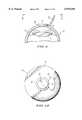
- FIG. 1is a side elevational view in section taken through the center of an eye showing the cornea, pupil and lens;
- FIG. 2is a perspective view of an embodiment of a universal blank according to the present invention.
- FIG. 3is a front elevational view of the embodiment shown in FIG. 2;
- FIG. 4is a top elevational view of the embodiment shown in FIG. 2;
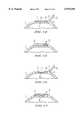
- FIG. 5is a side elevational view in section taken through the center of an eye showing formation of a flap-like structure at the front of the cornea;
- FIG. 6is a front elevational view of the cornea and flap-like structure as taken along lines VI--VI in FIG. 5;
- FIG. 7is a side elevational view in section taken through the center of an eye and showing the flap-like section positioned to expose an inner surface of the cornea;
- FIG. 8is an enlarged side elevational view in section taken through the center of an eye and showing placement of the embodiment of the universal blank shown in FIG. 2 on the exposed surface of the cornea;
- FIG. 9is an enlarged side elevational view in section taken through the center of an eye and illustrating the universal blank shown in FIG. 2 positioned on the exposed surface of the cornea;
- FIG. 10is a front elevational view of the cornea with the universal blank present on the exposed surface thereof as taken along lines X--X in FIG. 9;
- FIG. 11is an enlarged side elevational view in section taken through the center of the eye showing the cornea and the irradiation of a laser beam on the universal blank positioned on the exposed surface of the cornea;
- FIG. 12illustrates ablation of the center of the universal blank by the laser beam
- FIG. 13is a reduced front elevational view of the ablated universal blank taken along lines XIII--XIII in FIG. 12;
- FIG. 14is an enlarged cross-sectional view of the blank and cornea as taken along lines XIV--XIV in FIG. 13;
- FIG. 15is a side elevational view in section taken through the center of the eye showing the cornea and the flap-like portion reattached over the exposed surface of the cornea and the remaining portion of the ablatic universal blank shown in FIG. 14;
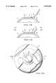
- FIG. 16is a side elevational view in section taken through the center of the eye illustrating ablation of the universal blank as well as a portion of the cornea below the blank by the laser beam;
- FIG. 17is a side elevational view in section taken through the center of the eye illustrating the flap-like portion repositioned over the remaining portion of the blank and ablated portion of the cornea;
- FIG. 18is a side elevational view in section taken through the center of the eye showing the cornea and the irradiation of a laser beam on other peripheral portions of the universal blank which is positioned on the exposed surface of the cornea;
- FIG. 19is a side elevational view in section taken through the center of the eye showing ablation of the portions of the universal blank by irradiation of the laser beam as shown in FIG. 18;
- FIG. 20is a reduced front elevational view taken along lines XX--XX in FIG. 19;
- FIG. 21is an enlarged cross-sectional view taken along lines XXI--XXI in FIG. 20;
- FIG. 22is a side elevational view in section taken through the center of the eye showing the cornea and the flap-like portion reattached over the exposed surface of the cornea and the remaining portion of the universal blank ablated by the laser beam as shown in FIG. 19;
- FIG. 23is a side elevational view in section taken through the center of the eye showing ablation of portions of the universal blank and the exposed surface of the cornea below the blank by irradiation of a laser beam;
- FIG. 24is a side elevational view in section taken through the center of the eye showing the cornea and the flap-like portion reattached over the exposed surface of the cornea and the remaining portion of the universal blank as ablated by the laser beam as shown in FIG. 23;
- FIG. 25is a side elevational view in section taken through the center of the eye showing ablation of multiple portions of the universal blank by irradiation of a laser beam;
- FIG. 26is a front elevational view of the ablated universal blank taken along lines XXVI--XXVI in FIG. 25;
- FIG. 27is a side elevational view in section taken through the center of the eye showing the cornea and the flap-like portion reattached over the exposed surface of the cornea and the remaining portion of the universal blank ablated by the laser beam as shown in FIG. 25;
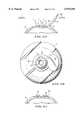
- FIG. 28is a side elevational view in section taken through the center of the eye showing ablation of multiple portions of the universal blank and cornea by irradiation of a laser beam;
- FIG. 29is a side elevational view in section taken through the center of the eye showing the cornea and the flap-like portion reattached over the exposed surface of the cornea and the remaining portion of the universal blank as ablated by the laser beam as shown in FIG. 28;
- FIG. 30is a side elevational view in section taken through the center of the eye showing ablation of the universal blank in a nonsymmetrical manner by irradiation of a laser beam;
- FIG. 31is a reduced front elevational view of the ablated universal blank taken along lines XXXI--XXXI in FIG. 30;
- FIG. 32is a side elevational view in section taken through the center of the eye showing the cornea and the flap-like portion reattached over the exposed surface of the cornea and the remaining portion of the universal blank as ablated by the laser beam as shown in FIG. 30;
- FIG. 33is a side elevational view in section taken through the center of the eye showing the cornea and the flap-like portion reattached over the exposed surface of the cornea and the remaining portion of the universal blank after a portion of the periphery of the universal blank and a portion of the exposed surface have been ablated by a laser beam;
- FIG. 34is a side elevational view in section taken through the center of the eye showing a central portion of the exposed surface of the cornea being ablated by a laser beam;
- FIG. 35is a reduced front elevational view of the ablated exposed surface of the cornea taken along lines XXXV--XXXV in FIG. 34;
- FIG. 36is a side elevational view in section taken through the center of the eye and illustrating the universal blank shown in FIG. 2 position on the ablated exposed surface of the cornea and ablation of a central portion of the universal blank by a laser beam;
- FIG. 37is a side elevational view in section taken through the center of the eye showing the cornea and flap-like portion reattached over the exposed surface of the cornea and the remaining portion of the universal blank as ablated by the laser beam as shown in FIG. 36;
- FIG. 38is a side elevational view in section taken through the center of the eye showing the cornea and the flap-like portion reattached over the exposed surface of the cornea and the remaining portion of the universal blank after a central portion of the universal blank and a central portion of the ablated exposed surface of the cornea have been ablated by a laser beam;
- FIG. 39is a side elevational view in section taken through the center of the eye showing ablation of peripheral portions of the universal blank which is positioned in the ablated exposed surface of the cornea;
- FIG. 40is a side elevational view in section taken through the center of the eye showing the cornea and the flap-like portion reattached over the exposed surface of the cornea and remaining portion of the universal blank as ablated by the laser beam as shown in FIG. 39;
- FIG. 41is a side elevational view in section taken through the center of the eye showing the cornea and flap-like portion reattached over the exposed surface of the cornea and the remaining portion of the universal blank after the periphery of the universal blank and a portion of the ablated exposed surface of the cornea surrounding the remaining portion of the blank have been ablated by a laser beam;
- FIG. 42is a side elevational view in section taken through the center of the eye showing the cornea and the flap-like portion reattached over the exposed surface of the cornea and a remaining portion of the universal blank which has been ablated in a nonsymmetrical manner by a laser beam;
- FIG. 43is a side elevational view in section taken through the center of the eye showing the cornea and the flap-like portion reattached over the exposed surface of the cornea and the remaining portion of the universal blank after a portion of the ablated exposed surface and universal blank have been ablated by a laser beam in a nonsymmetrical manner;
- FIG. 44is a side elevational view in section taken through the center of the eye showing the cornea and the flap-like portion reattached over the exposed surface of the cornea and the remaining portion of the universal blank of which multiple portions have been ablated by a laser beam;
- FIG. 45is a side elevational view in section taken through the center of the eye showing the cornea and the flap-like portion reattached over the exposed surface of the cornea and the remaining portion of the universal blank after multiple portions of the ablated portion of the exposed surface and multiple portions of the universal blank have been ablated by a laser beam;
- FIG. 46is a perspective view of another embodiment of a universal blank according to the present invention.
- FIG. 47is a front view of the embodiment shown in FIG. 46;
- FIG. 48is a bottom view of the embodiment shown in FIG. 46 as taken along lines XLVIII--XLVIII in FIG. 47;
- FIG. 49is a side elevational view in section taken through the center of the eye showing ablation of the exposed surface of the cornea by a laser beam to different depths;
- FIG. 50is a reduced front view of the cornea as taken along lines 50--50 in FIG. 49;
- FIG. 51is a side elevational view in section taken through the center of the eye showing the universal blank illustrated in FIG. 46 positioned on the exposed surface of the cornea after the exposed surface has been ablated as shown in FIG. 49;
- FIG. 52is a side elevational view in section taken through the center of the eye showing the cornea and the flap-like portion reattached over the exposed surface of the cornea and the remaining portion of the universal blank illustrated in FIG. 46 as ablated by the laser beam as shown in FIG. 51;
- FIG. 53is a side elevational view in section taken through the center of the eye showing the cornea and the flap-like portion reattached over the exposed surface of the cornea and the remaining portion of the universal blank shown in FIG. 46 after a central portion of the universal blank and a central portion of the ablated exposed surface of the cornea have been ablated by a laser beam;
- FIG. 54is a side elevational view in section taken through the center of the eye showing the cornea and the flap-like portion reattached over the exposed surface of the cornea and the remaining portion of the universal blank shown in FIG. 46 whose periphery has been ablated by a laser beam;
- FIG. 55is a side elevational view in section taken through the center of the eye showing the cornea and the flap-like portion reattached over the exposed surface of the cornea and the remaining portion of the universal blank after a portion of the periphery of the universal blank and a portion of the ablated exposed surface surrounding the remaining portion of the blank have been ablated by a laser beam;
- FIG. 56is a side elevational view in section taken through the center of the eye showing the cornea and the flap-like portion reattached over the exposed surface of the cornea and the remaining portion of the universal blank shown in FIG. 46 which has been ablated by the laser beam in a nonsymmetrical manner;
- FIG. 57is a side elevational view in section taken through the center of the eye showing the cornea and the flap-like portion reattached over the exposed surface of the cornea and the remaining portion of the universal blank shown in FIG. 46 after a portion of the universal blank and a portion of the ablated exposed surface have been ablated by the laser beam in a nonsymmetrical fashion;
- FIG. 58is a side elevational view in section taken through the center of the eye showing the cornea and the flap-like portion reattached over the exposed surface of the cornea and the remaining portion of the universal blank shown in FIG. 46 of which multiple portions have been by a laser beam;
- FIG. 59is a side elevational view in section taken through the center of the eye showing the cornea and the flap-like portion reattached over the exposed surface of the cornea and the remaining portion of the universal blank shown in FIG. 46 after multiple portions of the universal blank and multiple portions of the ablated exposed surface have been ablated by the laser beam.
- FIG. 1is a side elevational view in section taken through the center of an eye 10 which includes a cornea 12, a pupil 14 and a lens 16. If the cornea 12 and lens 16 do not cooperatively focus light correctly on the retina (not shown) of the eye to thus provide adequate vision, the curvature of the cornea can be modified to correct the refractive power of the cornea and thus correct the manner in which the light is focused with respect to the retina.
- FIGS. 2-4A universal blank 18 according to an embodiment of the present invention is illustrated in FIGS. 2-4.
- the universal blank according to this embodimentis disk-shaped and has a uniform or substantially uniform thickness throughout, as illustrated specifically in FIG. 3.
- the blank 18has a first planar or substantially planar surface 15, a second planar or substantially planar surface 17, and a periphery 19.
- the surfaces 15 and 17are arranged parallel or substantially parallel to each other with the periphery 19 being perpendicular or substantially perpendicular to one or both surfaces 15 and 17.
- the surfaces 15 and 17 and the periphery 19need not be uniform but could have recesses, projections, raised portions, or any variation in shape and texture.
- the universal blank 18has a diameter of about 4 to about 9 mm and a thickness of between about 20 to about 500 microns.
- the diameter and thickness of the disk-shaped universal blank 18can be of any practical size as would be appreciated by one skilled in the art.
- the universal blankneed not be disk-shaped although it is preferred as shown in the embodiment of FIGS. 2-4, but can be frusto-conical, oval, square, rectangle, or any practical shape as would be readily appreciated by one skilled in the art.
- the blank 18is preferably made of synthetic material, organic material, or a combination of both synthetic and organic material, that permits all or substantially all light having a wavelength in the visible spectrum to pass through, but absorbs all or substantially all light having a wavelength in a laser light spectrum.
- the blank 18can be made of collagen, copolymer collagen, polyethylene oxide or hydrogel, or cross-linked organic material such as collagen, hyaluronic acid, mucopolysaccharide or glycoprotein, to name a few.
- the blank 18is porous to allow oxygen and nutrients to pass therethrough.
- the blank 18can be made from a donor cornea of a human eye, or can be taken from a cultured cornea.
- the blank 18is not limited to those materials, and can be made of any suitable material, such as those disclosed in U.S. Pat. No. 4,994,058 to Raven et al., U.S. Pat. No. 4,718,418 to L'Esperance, U.S. Pat. No. 5,336,261 to Barrett et al., U.S. Pat. No. 4,840,175 to Peyman, and a publication by Jose I. Barraquer, M. D. entitled "Keratomileusis and Keratophakia in the Surgical Correction of Aphakia", the disclosures of which are hereby incorporated by reference herein.
- the blank 18is configured to be placed directly on an exposed inner surface of the cornea of the eye.
- a thin layer of the live corneamust be removed.
- a procedureis performed in which, for example, an incision 20 is made in the front portion of the cornea, as shown in FIG. 5.
- This incision 20is made so as to separate thin layer 22 of the cornea from the remaining portion of the cornea 12.
- the incisioncan be made with a scalpel, keratome, excimer laser, or any type of surgical cutting instrument known to one skilled in the art.
- the layer 22can also be separated from the surface of the live cornea by any other method which may not involve making an actual incision in the cornea as may be appreciated by one skilled in the art.
- the layer 22 of the corneacan be completely removed from the remaining portion of the cornea 12. However, as shown in FIGS. 5 and 6, it is preferable that the layer 22 of the cornea remain attached to the main portion of the live cornea 12 by an attaching or hinging portion 24. Accordingly, as shown in FIG. 7, the layer 22 of the cornea is formed as a flap-like layer that is pivotally moveable about the attaching portion 24 to expose an inner surface 26 of the cornea.
- the layer 22typically can be of any practical thickness, for example, 160 microns.
- the universal blank 18is then used to modify the curvature of the cornea in the following manner.
- the flap-like layer 22is positioned so as to expose the inner surface 26 of the cornea.
- the blank 18is then positioned on the exposed surface of the cornea at a position deemed suitable by the person performing the cornea modifying technique.
- the blank 18is positioned centrally or substantially centrally on the exposed surface 26 with the central longitudinal axis of the blank substantially coincident with the central optical axis of the eye.
- the blank 18need not be positioned centrally on the exposed surface 26 as shown, but rather, its central longitudinal axis can be offset from the central optical axis of the eye.
- the shape of the universal blankcan be modified sufficiently to influence the shape of the flap-like layer 22 and to thus change the refractive power of the flap-like layer sufficiently to correct the abnormality of the eye 10.
- every 10 micron change in curvature of the corneawill change the refractive power of the cornea by 1 diopter.
- a laser beam Lis directed to the first upper surface 15 of the blank 18 that is opposite to the second lower surface 17 of the blank 18 that is supported on the exposed surface 26 of the cornea 12.
- the laser beam Lcan be emitted from any type of laser 27 typically used in eye surgery methods, such as an excimer laser 27 or the like as described in U.S. Pat. No. 4,840,175.
- the laser beam Lwill begin to ablate or erode an area 32 of the blank 18 to which the laser beam is directed. Again, the area of the blank 18 to which the laser beam L is directed and which is ablated is selected to remedy a specific type of abnormality from which the eye is suffering.
- the laser beam Lwill be directed toward a central area 32 of the blank 18 so as to ablate that central area 32.
- the blank 18is disk-shaped, and the area 32 that is ablated is circular in top plan view and is at least initially in the form of a substantially hemispheric recess.
- the shape of the ablated areacan be any desired shape necessary to effect correction of the particular abnormality of the eye.
- the blank 18is made of a material that will absorb all or substantially all light having a wavelength within the laser light spectrum. Therefore, when the laser beam L is irradiated onto the blank 18, none or substantially none of the laser beam will pass through the blank 18 to ablate any portion of the cornea 12. However, as also previously stated, the material of the blank 18 will allow all or substantially all light having a wavelength within the visible light spectrum to pass therethrough.
- the laser beam Lcan be directed to the blank 18 until the ablated central area 32 becomes a hole with a frustoconical wall which passes entirely through the blank 18 to expose a portion 34 of the surface 26 of the cornea 12.
- the holecan have a cylindrically or substantially cylindrically shaped wall, or any other shape as would be formed by the laser beam L.
- none or essentially none of the surface 26 of the corneahas been ablated by the laser beam.
- the flap-like layer 22 of the corneais repositioned over the remaining portion of the blank 18 and the surface 26 of the cornea 12 as shown, for example, in FIG. 15.
- the shape of the remaining portion of the blank 18will influence the shape of the flap-like layer 22 when the flap-like layer is repositioned over the remaining portion of the blank 18 and surface 26 of the cornea 12.
- the refractive power of this flap-like layer 22will be changed due to this change in shape.
- the flap-like layer 22can be reattached to the cornea 12 by any known techniques such as suturing or the like.
- the material of the blank 18is transparent or essentially transparent to light having a wavelength within the visible light spectrum, visible light will pass through the remaining portion to the blank 18 and enter the eye 12.
- the flap-like layer 22will refract the light passing therethrough differently than prior to the reshaping. Therefore, in cooperation with the lens 16 (see FIG. 1), this reshaped layer 22 will focus the light in the appropriate manner on the retina, thus correcting the ametropic condition of the eye.
- the laser 27can be used to reduce the overall thickness of the blank 18 prior to shaping the blank.
- the blank 18can initially be about 500 microns thick for ease of handling. Then, once the blank 18 is positioned on the exposed inner surface of the cornea in the manner described above, the inner beam L can be directed to the upper surface 15 of the blank so as to reduce the overall thickness of the blank 18 as desired.
- a 500 micron thick blankcan be reduced, for example, to about 100 microns or any suitable thickness by the laser beam L before the laser beam L is used to sculpt the blank 18 to a particular shape as shown, for example, in FIGS. 11-15.
- the laser beam Lcan be irradiated onto the area 32 of the blank 18 until the area 32 of the blank 18 is completely ablated by the laser beam and becomes a hole that passes entirely through the blank 18. Afterward, the laser beam L is directed onto the exposed portion of the surface 26 of the cornea so as to ablate a portion 36 of that surface.
- the laser beam Lcan be directed toward the outer perimeter of the blank as shown, for example, in FIGS. 18-21.
- the blank 18is made of a material which will absorb all or substantially all of the laser beam. Therefore, as shown in FIG. 19 specifically, the blank 18 will be ablated by the laser beam, but none or substantially none of the surface 26 of the cornea 12 below the ablated area 38 of the blank will be ablated.
- the laser beam Lcan be irradiated onto the ablated area 38 of the blank 18 until that area 38 is ablated down to the surface 26 of the cornea on which the blank 18 is positioned, and the remaining portion of blank 18 thus has a frustoconical shape.
- the blank 18can be shaped in any manner by the laser beam L.
- the flap-like layer 22is then repositioned over the remaining portion of the blank 18 so that the remaining portion of the blank 18 influences the shape of the repositioned flap-like layer 22. Since the material of the blank 18 is transparent or substantially transparent to light having a wavelength in the visible light spectrum, visible light will pass through the remaining portion of the blank 18.
- the flap-like layer 22has a different refractive power, the flap-like layer 22 will refract the light passing therethrough differently than prior to the reshaping. Therefore, in cooperation with the lens 16 (see FIG. 1), this reshaped layer 22 will focus the light in the appropriate manner on the retina, thus correcting the ametropic condition of the eye.
- the laser beam Lcan be directed onto the surface 26 of the cornea 12 in order to ablate a portion 40 of that surface 26 as shown, for example, in FIG. 23.
- the ablated portion 40 of the surface 26will also influence the shape of the repositioned flap-like layer 22. Accordingly, the thickness of the blank 18 need not be increased in order to increase the degree to which the flap-like layer 22 is reshaped. High myopic conditions up to 35 diopter can be corrected by using this technique.
- any portion or portions of the blank 18can be ablated to a degree necessary to correct the ametropic condition of the eye.
- the laser beam Lcan be directed toward a central area 32 of the blank 18 and also toward the 38 of the blank 18 to ablate inner and outer areas 32 and 38.
- FIG. 27when the flap-like layer 22 is repositioned over the surface 26 of the cornea and the remaining portion of the blank 18, the remaining portion of the blank 18 will influence the shape of the flap-like layer 22.
- any portion or amount of the exposed surface of the cornea 26can be ablated as well, as long as a sufficient amount (e.g., 200 microns) of cornea is left remaining so that the remaining cornea does not experience instability or outbulging (eklasia).
- the laser beam Lcan be directed toward the surface 26 of the cornea underneath the ablated portions 32 and 38 of the blank 18 to ablate those portions 36 and 40 of the surface 26 of the cornea 12. Accordingly, as shown in FIG. 29, the remaining portion of the blank 18 and the ablated portions 36 and 40 of the surface 26 of the cornea 12 will influence the shape of the flap-like layer 22 when the flap-like layer 22 is repositioned over the remaining portion of the blank 18 and surface 26 of the cornea.
- the laser beam Lcan be directed onto the blank 18 to ablate the blank in a nonsymmetrical manner.
- This type of shaping of the blank 18is usually done to correct an astigmatic condition of the eye.
- the blankcan be sculpted to assume a substantially hemispherical shape resembling one-half of an egg as cut along the longitudinal axis of the egg.
- the blank 18can assume a substantially hemispherical shape having a varying radius.
- only a portion 42 of the right-side periphery of the blank 18is ablated. Accordingly, as shown in FIG. 32, the remaining portion of the blank 18 will influence the shape of the flap-like layer 22 when the flap-like layer 22 is repositioned over the remaining portion of a blank 18 and surface of the cornea 26.
- any portion or amount of the exposed surface of the cornea 26can be ablated in a nonsymmetrical manner as well, as long as a sufficient amount of cornea (e.g., about 200 microns) is left remaining so that the remaining cornea does not experience instability or outbulging (eklasia).
- the laser beam Lis directed onto the portion of the disk 18 to be ablated, and after that portion has been ablated, the laser beam L is directed onto the surface of the cornea 26 below the ablated portion of the blank in a manner similar to that described, for example, with regard to FIG. 16 until a portion 44 of the surface 26 is ablated.
- the flap-like layer 22is repositioned over the remaining portion of the blank 18 and the surface 26 of the cornea so that the remaining portion of the blank 18 and the ablated portion 44 of the surface 26 of the cornea 12 will influence the shape of the flap-like layer 22.
- FIG. 34shows another embodiment of the method for using a universal blank according to the present invention.
- that surface 26can be ablated by a laser beam before the blank 18 is positioned thereon.
- the laser beam Lis directed onto that exposed surface 26 to ablate the cornea 12 down to a particular depth.
- the surface 26can be ablated to any amount up to a depth of about 300 microns, which would leave a sufficient amount (e.g., about 200 microns) of cornea left remaining so that the cornea does not experience instability or outbulging as discussed above.
- the ablated section 46 of the surface 26can be symmetrical about the center of the front portion of the cornea as shown in FIG. 35.
- the shape of the ablated section 46will coincide with the shape of the blank 18 that is used in modifying the cornea.
- the blank 18is disk-shaped and hence, the ablated section 46 is circular.
- the diameter of the ablated sectionwill coincide or substantially coincide with the diameter of the disk 18.
- the shape of the ablated section 46can be asymmetrical, for example, and can vary to accommodate a disk having any shape as would be appreciative by one skilled in the art.
- the center of the ablated sectionneed not coincide with the optical axis of the eye, but rather could be offset from the optical axis.
- the edge 48 of the ablated section 46will abut against the periphery 19 of the disk as shown in FIG. 36, thereby preventing or substantially preventing the disk 18 from moving laterally on the surface 26 of the cornea.
- the edge 48need not contact the entire periphery 19 to achieve this function.
- the disk 18can be ablated in the manner discussed above with regard to FIGS. 11-14 so that a recess or hole is formed in the center or substantially in the center of the blank 18.
- the ablationis stopped at the exposed ablated section 46 of the surface 26 so that none or substantially none of the ablated section 46 is further ablated.
- the flap-like layer 22is then repositioned over the remaining portion of the blank 18 so that the remaining portion of the blank 18 and the central portion 50 of the exposed ablated section 46 influences the shape of the repositioned flap-like layer 22.
- the laser beam Lcan be directed onto the blank 18 and the exposed ablated section 46 in a manner similar to that described above with regard to FIG. 16. By doing this, a portion 52 of the ablated section 46 of the exposed surface 26 is further ablated.
- the ablated section 46can be ablated by any amount as long as a sufficient amount (e.g., about 200 microns) of cornea 12 is left remaining. In this example, the remaining portion of the blank 18 and the ablated portion 52 of the exposed ablated section 46 influences the shape of the flap-like layer 22 when the flap-like layer is repositioned over the blank 18 and the exposed surface 26 of the cornea.
- the periphery of the blank 18can be ablated in the manner similar to that discussed above with regard to FIG. 21. As shown, none or substantially none of the previously ablated surface 46 of the exposed surface 26 is ablated by the laser beam. Accordingly, as shown in FIG. 40, the remaining portion of the blank 18 and the ablated section 46 of the exposed surface of the cornea influences the shape of the flap-like layer 22 when the flap-like layer is repositioned over the blank and the exposed surface 26. Alternatively, as shown in FIG. 41, a portion 54 of the ablated section 46 of the exposed surface 26 can be further ablated by the laser beam. In this event, when the flap-like layer 22 is repositioned over the exposed surface 26 and the remaining portion 18 of the blank, the ablated portion 54 and remaining portion of the blank 18 influence the shape of the flap-like layer 22.
- a portion of the blank 18 alone or a portion of the blank 18 and a portion 56 of the ablated section 46 of the exposed surface 26 of the cornea 12can be ablated in a nonsymmetrical manner. Accordingly, when the flap-like layer 22 is repositioned over the exposed surface 26 and the remaining portion of the blank, the shape of the remaining portion of the blank 18 and the ablated portion 56 influence the shape of the flap-like layer 22.
- multiple portions of the blank 18 alone or multiple portions of the blank and multiple portions 58 of the ablated section 46 of the exposed surface 26can be ablated by the laser beam. Accordingly, the remaining portion of the blank 18, and the ablated portions 58 of the ablated section 46 of the exposed surface influence the shape of the flap-like layer 22 when the flap-like layer is repositioned over the remaining portion of the blank 18 and the exposed surface 26.
- FIGS. 46-48Another embodiment of the universal blank according to the present invention is shown in FIGS. 46-48.
- the blank 60 shown in FIG. 46has a large portion 62 and a small portion 64.
- the large portion 62can have any practical size and shape as could the blank 18 shown in FIG. 2 as discussed above, and can be made of the same type of materials as the blank 18.
- the large portion 62 of the blank 60is disk-shaped and has a diameter of about 4 to about 9 millimeters and a thickness of between about 20 and about 500 microns.
- the diameter and thickness of the blank 60can be of any practical size that would be appreciated by one skilled in the art.
- the small portion 64 of the blank 60is also disk-shaped, but has a small diameter than the large portion 62.
- the diameter of small portion 64can be any practical size, such as a small disk-shaped projection having a nominal diameter up to a disk-shaped projection having a diameter only a fraction smaller than the diameter of the large shaped portion 62.
- the small portion 64need not be disk-shaped, but can have any practical shape as would be appreciative by one skilled in the art.
- the large portion 62 and small portion 64can have shapes different from each other. Hence, for example, the large portion 62 can be disk-shaped while the small portion 64 can be oval or rectangularly shaped.
- the large portion 62has a first planar or substantially planar surface 63, a second planar or substantially planar surface 65, and a periphery 66.
- the surfaces 63 and 65can be parallel or substantially parallel to each other, and the periphery 66 can be perpendicular to one or both of the surfaces 63 and 65.
- the surfaces 63 and 65 and the periphery 66need not be smooth but can have projected portions, recesses or any type of texture.
- the small portion 64is integral with or attachable to the large portion 62 and a planar or substantially surface 68 and a periphery 69.
- the surface 68can be parallel or substantially parallel to one or both of the surfaces 63 and 65 of the large portion 62, and the periphery 69 could be perpendicular or substantially perpendicular to the surface 68.
- the surface 68 and periphery 69need not be smooth but can have projected portions, recesses or any type of texture.
- FIG. 49An embodiment of a method for using the universal blank 60 according to the present invention is shown in FIG. 49. Specifically, the surface of the cornea 26 that has been exposed by forming and positioning the flap-like layer 22 in the manner discussed above is ablated in the manner shown in FIG. 49. That is, the exposed surface 26 is ablated to different depths so as to assume a shape which can accommodate the blank 60. Hence, an outer section 70 of the exposed surface 26 is ablated to a first depth, while an inner section 71 is ablated to a second depth greater than the first depth.
- the depths of the ablated inner and outer sections 70 and 71can be any amount which would allow a sufficient amount of cornea 12 (e.g., about 200 microns) to remain so that the remaining cornea does not experiencing distortion or outbulging. It is noted that this step-shaped blank 60 provides an advantage over a uniformly shaped blank 18 in this regard, because less volume of cornea can be ablated to form a recess which will accommodate the smaller portion 64 of the blank 60 and thus point the blank 60 from shifting on the surface of the cornea. That is, the volume of cornea removed to form section 71 is less than the volume of cornea removed to form section 46 (FIG. 34).
- the blank 60is positioned on the ablated sections 70 and 71 of the exposed surface 26 so that the surface 68 of the small portion 64 of the blank 60 contacts or substantially contacts the ablated section 71 while the surface 65 of the large portion 62 of the blank 60 contacts or substantially contacts the ablated section 70 as shown.
- an edge 72 of the ablated section 71contacts the periphery 66 of the large portion of the blank 60, while an edge 74 of the ablated section 71 contacts the periphery 69 of the small portion 64 of the blank 60.
- the sizes and shapes of the ablated section 70 and 71can be made to conform or substantially conform with the sizes and shapes of the large and small portions 62 and 64, respectively, of the blank 60, and can thus be any practical size and shape as would be appreciated by one skilled in the art.
- the ablated sections 70 and 71need not be made symmetrical about the central optical axis of the eye, but rather, could be offset from the central optical axis of the eye and from each other.
- the edges 72 and 74 of the ablated sections 70 and 71, respectively,can contact the peripheries 66 and 69, respectively, in their entirety or at various locations.
- the laser beam Lis irradiated onto the blank 60 in a manner similar to that described above with regard to FIGS. 11-14 to ablate a central or substantially central portion of the blank 60 as shown in FIG. 52.
- That ablated portioncan be, for example, a substantially hemispherical recess as discussed above with regard to FIGS. 11-14.
- none or substantially none of the ablated section 71is further ablated by this laser beam. Accordingly, the surface of the ablated section 71 and the remaining portion of the blank 60 influence the shape of the flap-like layer 22 when the flap-like layer 22 is repositioned over the blank 60 and the exposed surface 26.
- a portion 76 of the ablated section 71 below the ablated portion of the blank 60can be further ablated by the laser beam to any depth which would allow a sufficient amount (e.g., about 200 microns) of the cornea 12 to remain. Accordingly, the ablated portion 76 and remaining portion of the blank 60 influence the shape of the flap-like layer 22 when the flap-like layer 22 is repositioned back over the exposed surface 26 and the remaining portion of the disk 60.
- multiple portion of the blank 60can be ablated in a manner similar to that in which the blank 18 is ablated as described, for example, with respect to FIGS. 18-22 above.
- the laser beamcan be directed onto the ablated section 70 of the exposed surface 26 to ablate portion 78 of that ablated section 70.
- the remaining portion of the blank 60 and the ablated section 70influence the shape of the flap-like layer 22 when the flap-like layer 22 is repositioned over the exposed surface 26 and the remaining portion of the blank 60.
- FIG. 54the remaining portion of the blank 60 and the ablated section 70 influence the shape of the flap-like layer 22 when the flap-like layer 22 is repositioned over the exposed surface 26 and the remaining portion of the blank 60.
- the remaining portion of the blank 60 and the further ablated portion 78 of the ablated section 70 of the exposed surface 26influence the shape of the flap-like layer 22 when the flap-like layer 22 is repositioned over the exposed surface 26 in the remaining portion of the blank 60.
- the blank 60 and ablated section 70 of the exposed surface 26can be ablated by the laser beam in a nonsymmetrical manner. Accordingly, as shown in FIG. 56, the remaining portion of the blank 60 and the ablated section 70 influence the shape of the flap-like layer 22 when the flap-like layer is repositioned over the surface 26 in the remaining portion of the blank 60. As shown in FIG. 57, the nonsymmetrical ablated portion 80 and the remaining portion of the blank 60 influence the shape of the flap-like layer 22 when the flap-like layer is repositioned over the exposed surface 26 and the remaining portion of the blank 60.
- the blank 60 and ablated section 70can be ablated at multiple locations in a manner similar to that in which the blank 18 and surface 26 are ablated as described above with regard to FIGS. 25-29. Accordingly, as shown in FIG. 58, the remaining portion of the blank 60 and the ablated sections 70 and 71 of the exposed surface 26 influence the shape of the flap-like layer 22 when the flap-like layer 22 is repositioned over the exposed surface 26 and the blank 60. Alternatively, as shown in FIG.
- the further ablated portion 82 of the ablated section 70, the further ablated portion 84 of the ablated section 71, and the remaining portion of the blank 60influence the shape of the flap-like layer 22 when the flap-like layer 22 is repositioned over the remaining portion blank 60 and the exposed surface 26.
Landscapes
- Health & Medical Sciences (AREA)
- Ophthalmology & Optometry (AREA)
- Animal Behavior & Ethology (AREA)
- General Health & Medical Sciences (AREA)
- Veterinary Medicine (AREA)
- Engineering & Computer Science (AREA)
- Biomedical Technology (AREA)
- Heart & Thoracic Surgery (AREA)
- Vascular Medicine (AREA)
- Life Sciences & Earth Sciences (AREA)
- Public Health (AREA)
- Physics & Mathematics (AREA)
- Optics & Photonics (AREA)
- Nuclear Medicine, Radiotherapy & Molecular Imaging (AREA)
- Surgery (AREA)
- Oral & Maxillofacial Surgery (AREA)
- Cardiology (AREA)
- Transplantation (AREA)
- Laser Surgery Devices (AREA)
- Prostheses (AREA)
Abstract
Description
Claims (25)
Priority Applications (12)
| Application Number | Priority Date | Filing Date | Title |
|---|---|---|---|
| US08/845,448US5919185A (en) | 1997-04-25 | 1997-04-25 | Universal implant blank for modifying corneal curvature and methods of modifying corneal curvature therewith |
| PCT/US1998/004680WO1998048715A1 (en) | 1997-04-25 | 1998-03-11 | A universal implant blank for modifying corneal curvature and methods of modifying corneal curvature therewith |
| AU64567/98AAU739297B2 (en) | 1997-04-25 | 1998-03-11 | A universal implant blank for modifying corneal curvature and methods of modifying corneal curvature therewith |
| CA002286718ACA2286718C (en) | 1997-04-25 | 1998-03-11 | A universal implant blank for modifying corneal curvature and methods of modifying corneal curvature therewith |
| CN98804498ACN1253484A (en) | 1997-04-25 | 1998-03-11 | Universal graft blank for correcting corneal curvature and method for correcting corneal curvature using same |
| JP10546959AJP2000513986A (en) | 1997-04-25 | 1998-03-11 | Universal injection blank for correcting corneal strain and method for correcting corneal strain using the same |
| EP98910287AEP1014872A4 (en) | 1997-04-25 | 1998-03-11 | A universal implant blank for modifying corneal curvature and methods of modifying corneal curvature therewith |
| KR1019997009713AKR100600210B1 (en) | 1997-04-25 | 1998-03-11 | Universal transplant blank for corneal refractive index correction and corneal refractive index correction method |
| BR9809289-8ABR9809289A (en) | 1997-04-25 | 1998-03-11 | Universal implant model for corneal curvature modification and corneal curvature modification processes using it |
| US09/260,591US6063073A (en) | 1997-04-25 | 1999-03-02 | Universal implant blank for modifying corneal curvature and methods of modifying corneal curvature therewith |
| US09/260,571US6280470B1 (en) | 1995-10-20 | 1999-03-02 | Intrastromal corneal modification |
| US09/797,177US20010034516A1 (en) | 1997-04-25 | 2001-03-02 | Universal implant blank for modifying corneal curvature and methods of modifying corneal curvature therewith |
Applications Claiming Priority (1)
| Application Number | Priority Date | Filing Date | Title |
|---|---|---|---|
| US08/845,448US5919185A (en) | 1997-04-25 | 1997-04-25 | Universal implant blank for modifying corneal curvature and methods of modifying corneal curvature therewith |
Related Parent Applications (1)
| Application Number | Title | Priority Date | Filing Date |
|---|---|---|---|
| US08/546,148Continuation-In-PartUS6221067B1 (en) | 1995-10-20 | 1995-10-20 | Corneal modification via implantation |
Related Child Applications (3)
| Application Number | Title | Priority Date | Filing Date |
|---|---|---|---|
| US09/260,591Continuation-In-PartUS6063073A (en) | 1997-04-25 | 1999-03-02 | Universal implant blank for modifying corneal curvature and methods of modifying corneal curvature therewith |
| US09/260,571Continuation-In-PartUS6280470B1 (en) | 1995-10-20 | 1999-03-02 | Intrastromal corneal modification |
| US09/260,570ContinuationUS6197019B1 (en) | 1994-04-25 | 1999-03-02 | Universal implant blank for modifying corneal curvature and methods of modifying corneal curvature therewith |
Publications (1)
| Publication Number | Publication Date |
|---|---|
| US5919185Atrue US5919185A (en) | 1999-07-06 |
Family
ID=25295261
Family Applications (1)
| Application Number | Title | Priority Date | Filing Date |
|---|---|---|---|
| US08/845,448Expired - LifetimeUS5919185A (en) | 1995-10-20 | 1997-04-25 | Universal implant blank for modifying corneal curvature and methods of modifying corneal curvature therewith |
Country Status (9)
| Country | Link |
|---|---|
| US (1) | US5919185A (en) |
| EP (1) | EP1014872A4 (en) |
| JP (1) | JP2000513986A (en) |
| KR (1) | KR100600210B1 (en) |
| CN (1) | CN1253484A (en) |
| AU (1) | AU739297B2 (en) |
| BR (1) | BR9809289A (en) |
| CA (1) | CA2286718C (en) |
| WO (1) | WO1998048715A1 (en) |
Cited By (76)
| Publication number | Priority date | Publication date | Assignee | Title |
|---|---|---|---|---|
| US6019754A (en)* | 1998-10-29 | 2000-02-01 | Kawesch; Glenn | Method and apparatus for improving lasik flap adherence |
| US6063073A (en)* | 1997-04-25 | 2000-05-16 | Peyman; Gholam A. | Universal implant blank for modifying corneal curvature and methods of modifying corneal curvature therewith |
| US6280470B1 (en)* | 1995-10-20 | 2001-08-28 | Gholam A. Peyman | Intrastromal corneal modification |
| US20010027314A1 (en)* | 1995-10-20 | 2001-10-04 | Peyman Gholam A. | Intrastromal corneal modification via laser |
| US6361560B1 (en)* | 1998-12-23 | 2002-03-26 | Anamed, Inc. | Corneal implant and method of manufacture |
| WO2002006883A3 (en)* | 2000-07-18 | 2002-05-23 | Edward Perez | Pre-fabricated corneal tissue lens and method of corneal overlay to correct vision (ii) |
| US6436092B1 (en) | 2000-03-21 | 2002-08-20 | Gholam A. Peyman | Adjustable universal implant blank for modifying corneal curvature and methods of modifying corneal curvature therewith |
| US6458141B1 (en) | 2000-03-10 | 2002-10-01 | Gholam A. Peyman | Method and apparatus for creating a flap in the cornea and incisions or shrinkage under the flap to correct vision disorders |
| US20030018348A1 (en)* | 2001-07-23 | 2003-01-23 | Ioannis Pallikaris | Device for separating the epithelium layer from the surface of the cornea of an eye |
| WO2003022168A1 (en)* | 2001-09-10 | 2003-03-20 | Gholam Peyman | Ablatable intracorneal inlay with predetermined refractive properties |
| US6551307B2 (en) | 2001-03-23 | 2003-04-22 | Gholam A. Peyman | Vision correction using intrastromal pocket and flap |
| US6589280B1 (en) | 2001-05-11 | 2003-07-08 | Jeffrey E. Koziol | Method for producing a multifocal corneal surface using intracorneal microscopic lenses |
| US6702832B2 (en)* | 1999-07-08 | 2004-03-09 | Med Logics, Inc. | Medical device for cutting a cornea that has a vacuum ring with a slitted vacuum opening |
| US6786926B2 (en) | 2001-11-09 | 2004-09-07 | Minu, L.L.C. | Method and apparatus for alignment of intracorneal inlay |
| US20040186567A1 (en)* | 2003-03-18 | 2004-09-23 | Kawesch Gary M. | Method for improving corneal inlays |
| US20040243231A1 (en)* | 2001-05-11 | 2004-12-02 | Koziol Jeffrey E. | Intracorneal lens system having connected lenses |
| US20050014503A1 (en)* | 2000-11-17 | 2005-01-20 | Kabushiki Kaisha Toshiba | Scheme for registration and authentication in wireless communication system using wireless LAN |
| US6855163B2 (en) | 2002-07-19 | 2005-02-15 | Minu, Llc | Gradual correction of corneal refractive error using multiple inlays |
| US20050055041A1 (en)* | 2003-09-05 | 2005-03-10 | Sightrate B.V. | Device for separation of corneal epithelium |
| US20050113911A1 (en)* | 2002-10-17 | 2005-05-26 | Peyman Gholam A. | Adjustable intraocular lens for insertion into the capsular bag |
| US20050143717A1 (en)* | 2001-04-27 | 2005-06-30 | Peyman Gholam A. | Method of treatment of refractive errors using subepithelial or intrastromal corneal inlay with bonding coating |
| US20050149006A1 (en)* | 2001-11-07 | 2005-07-07 | Peyman Gholam A. | Device and method for reshaping the cornea |
| US6918904B1 (en) | 2001-11-07 | 2005-07-19 | Minu, L.L.C. | Method of reshaping the cornea by controlled thermal delivery |
| US20050177149A1 (en)* | 2001-11-07 | 2005-08-11 | Peyman Gholam A. | Method and apparatus for reshaping the cornea by controlled thermal delivery |
| US20050178394A1 (en)* | 2003-08-21 | 2005-08-18 | Intralens Vision, Inc. | Method for keratophakia surgery |
| US20050182488A1 (en)* | 2001-04-27 | 2005-08-18 | Peyman Gholam A. | Implant and method for altering the refractive properties of the eye |
| US20050182489A1 (en)* | 2001-04-27 | 2005-08-18 | Peyman Gholam A. | Intraocular lens adapted for adjustment via laser after implantation |
| US6949093B1 (en) | 2000-03-21 | 2005-09-27 | Minu, L.L.C. | Adjustable universal implant blank for modifying corneal curvature and methods of modifying corneal curvature therewith |
| US20050222679A1 (en)* | 2001-04-27 | 2005-10-06 | Peyman Gholam A | Bifocal implant and method for altering the refractive properties of the eye |
| US20050288696A1 (en)* | 2001-07-23 | 2005-12-29 | Pallikaris Ioannis G | Device for separating the epithelial layer from the surface of the cornea of an eye |
| US6989008B2 (en) | 2001-03-23 | 2006-01-24 | Minu Llc | Adjustable ablatable inlay |
| US20060084949A1 (en)* | 2000-03-21 | 2006-04-20 | Peyman Gholam A | Method and apparatus for accommodating intraocular lens |
| US20060116762A1 (en)* | 2004-11-30 | 2006-06-01 | Xin Hong | Aspheric lenticule for keratophakia |
| US20060216329A1 (en)* | 2000-03-21 | 2006-09-28 | Peyman Gholam A | Drug delivery system and method |
| US20070088415A1 (en)* | 2001-11-07 | 2007-04-19 | Minu Llc | Method of treating the eye using controlled heat delivery |
| US20070100443A1 (en)* | 2005-10-27 | 2007-05-03 | Peyman Gholam A | Intraocular lens adapted for accommodation via electrical signals |
| US20070142828A1 (en)* | 2001-11-07 | 2007-06-21 | Minu, Llc | Method and system for altering the refractive properties of the eye |
| US20080039769A1 (en)* | 2001-11-07 | 2008-02-14 | Minu Llc | Method of medical treatment using controlled heat delivery |
| US7404637B2 (en) | 1999-03-01 | 2008-07-29 | Boston Innovative Optics, Inc. | System and method for increasing the depth of focus of the human eye |
| US20080275433A1 (en)* | 2007-04-26 | 2008-11-06 | Carl Zeiss Meditec Ag | Apparatus and method for generating cut surfaces in the cornea of an eye for correction of ametropia |
| US7497866B2 (en) | 2000-07-18 | 2009-03-03 | Tissue Engineering Refraction Inc. | Methods for producing epithelial flaps on the cornea and for placement of ocular devices and lenses beneath an epithelial flap or membrane, epithelial delaminating devices, and structures of epithelium and ocular devices and lenses |
| US7585075B2 (en) | 2004-05-20 | 2009-09-08 | Forsight Labs, Llc | Corneal onlays and wavefront aberration correction to enhance vision |
| US20090299348A1 (en)* | 2002-05-31 | 2009-12-03 | Ruscio Dominic V | Polymeric Materials for Use as Photoablatable Inlays |
| US7628810B2 (en) | 2003-05-28 | 2009-12-08 | Acufocus, Inc. | Mask configured to maintain nutrient transport without producing visible diffraction patterns |
| US7776086B2 (en) | 2004-04-30 | 2010-08-17 | Revision Optics, Inc. | Aspherical corneal implant |
| US7828844B2 (en) | 2002-09-13 | 2010-11-09 | Forsight Labs, Llc | Inserting lenses into corneal epithelial pockets to improve vision |
| US7883520B2 (en) | 2006-04-10 | 2011-02-08 | Forsight Labs, Llc | Corneal epithelial pocket formation systems, components and methods |
| US7976577B2 (en) | 2005-04-14 | 2011-07-12 | Acufocus, Inc. | Corneal optic formed of degradation resistant polymer |
| US8057541B2 (en) | 2006-02-24 | 2011-11-15 | Revision Optics, Inc. | Method of using small diameter intracorneal inlays to treat visual impairment |
| US8079706B2 (en) | 2003-06-17 | 2011-12-20 | Acufocus, Inc. | Method and apparatus for aligning a mask with the visual axis of an eye |
| USD656526S1 (en) | 2009-11-10 | 2012-03-27 | Acufocus, Inc. | Ocular mask |
| US8162953B2 (en) | 2007-03-28 | 2012-04-24 | Revision Optics, Inc. | Insertion system for corneal implants |
| US8469948B2 (en) | 2010-08-23 | 2013-06-25 | Revision Optics, Inc. | Methods and devices for forming corneal channels |
| US8668735B2 (en) | 2000-09-12 | 2014-03-11 | Revision Optics, Inc. | Corneal implant storage and delivery devices |
| US8900296B2 (en) | 2007-04-20 | 2014-12-02 | Revision Optics, Inc. | Corneal inlay design and methods of correcting vision |
| US9005281B2 (en) | 2009-08-13 | 2015-04-14 | Acufocus, Inc. | Masked intraocular implants and lenses |
| US9005280B2 (en) | 2000-09-12 | 2015-04-14 | Revision Optics, Inc. | System for packaging and handling an implant and method of use |
| US9204962B2 (en) | 2013-03-13 | 2015-12-08 | Acufocus, Inc. | In situ adjustable optical mask |
| US9271828B2 (en) | 2007-03-28 | 2016-03-01 | Revision Optics, Inc. | Corneal implant retaining devices and methods of use |
| US9345569B2 (en) | 2011-10-21 | 2016-05-24 | Revision Optics, Inc. | Corneal implant storage and delivery devices |
| US9427311B2 (en) | 2009-08-13 | 2016-08-30 | Acufocus, Inc. | Corneal inlay with nutrient transport structures |
| US9427922B2 (en) | 2013-03-14 | 2016-08-30 | Acufocus, Inc. | Process for manufacturing an intraocular lens with an embedded mask |
| US9539143B2 (en) | 2008-04-04 | 2017-01-10 | Revision Optics, Inc. | Methods of correcting vision |
| US9545303B2 (en) | 2011-12-02 | 2017-01-17 | Acufocus, Inc. | Ocular mask having selective spectral transmission |
| US9549848B2 (en) | 2007-03-28 | 2017-01-24 | Revision Optics, Inc. | Corneal implant inserters and methods of use |
| US9681800B2 (en) | 2005-10-27 | 2017-06-20 | The Arizona Board Of Regents On Behalf Of The University Of Arizona | Holographic adaptive see-through phoropter |
| US9943403B2 (en) | 2014-11-19 | 2018-04-17 | Acufocus, Inc. | Fracturable mask for treating presbyopia |
| US10004593B2 (en) | 2009-08-13 | 2018-06-26 | Acufocus, Inc. | Intraocular lens with elastic mask |
| US10092393B2 (en) | 2013-03-14 | 2018-10-09 | Allotex, Inc. | Corneal implant systems and methods |
| US10449090B2 (en) | 2015-07-31 | 2019-10-22 | Allotex, Inc. | Corneal implant systems and methods |
| US10555805B2 (en) | 2006-02-24 | 2020-02-11 | Rvo 2.0, Inc. | Anterior corneal shapes and methods of providing the shapes |
| US10583041B2 (en) | 2015-03-12 | 2020-03-10 | RVO 2.0 Inc. | Methods of correcting vision |
| US10687935B2 (en) | 2015-10-05 | 2020-06-23 | Acufocus, Inc. | Methods of molding intraocular lenses |
| US10835371B2 (en) | 2004-04-30 | 2020-11-17 | Rvo 2.0, Inc. | Small diameter corneal inlay methods |
| US11364110B2 (en) | 2018-05-09 | 2022-06-21 | Acufocus, Inc. | Intraocular implant with removable optic |
| US11464625B2 (en) | 2015-11-24 | 2022-10-11 | Acufocus, Inc. | Toric small aperture intraocular lens with extended depth of focus |
Families Citing this family (6)
| Publication number | Priority date | Publication date | Assignee | Title |
|---|---|---|---|---|
| US6626941B2 (en) | 1998-12-23 | 2003-09-30 | Anamed, Inc. | Corneal implant and method of manufacture |
| US6908484B2 (en) | 2003-03-06 | 2005-06-21 | Spinecore, Inc. | Cervical disc replacement |
| JP2008509748A (en)* | 2004-08-13 | 2008-04-03 | オタワ ヘルス リサーチ インスティテュート | Visual enhancement ophthalmic device and related methods and compositions |
| EP2317962B1 (en)* | 2008-06-20 | 2013-11-27 | WaveLight GmbH | Device for cutting a tissue part with focussed laser radiation |
| US9974690B2 (en) | 2009-03-23 | 2018-05-22 | Wavelight Gmbh | Apparatus and method for LASIK |
| RU2505273C2 (en)* | 2009-03-23 | 2014-01-27 | Уэйвлайт Гмбх | Method for laser intrastromal keratomileusis |
Citations (11)
| Publication number | Priority date | Publication date | Assignee | Title |
|---|---|---|---|---|
| US4505855A (en)* | 1982-09-30 | 1985-03-19 | Massachusetts General Hospital | Transparent non-fibrilized collagen material by ultracentrifugation |
| US4676790A (en)* | 1985-09-25 | 1987-06-30 | Kern Seymour P | Method of manufacture and implantation of corneal inlays |
| US4678422A (en)* | 1985-11-12 | 1987-07-07 | York Kenneth K | Systems and methods for precise, accurate formation of products by photoablation |
| US4718418A (en)* | 1983-11-17 | 1988-01-12 | Lri L.P. | Apparatus for ophthalmological surgery |
| US4807623A (en)* | 1986-05-30 | 1989-02-28 | David M. Lieberman | Device for simultaneously forming two incisions along a path on an eye |
| US4840175A (en)* | 1986-12-24 | 1989-06-20 | Peyman Gholam A | Method for modifying corneal curvature |
| US4994058A (en)* | 1986-03-19 | 1991-02-19 | Summit Technology, Inc. | Surface shaping using lasers |
| US5123921A (en)* | 1987-09-14 | 1992-06-23 | Nestle S.A. | Synthetic intracorneal lines and method of manufacture |
| US5196026A (en)* | 1991-09-16 | 1993-03-23 | Chiron Ophthalmics, Inc. | Method of implanting corneal inlay lenses smaller than the optic zone |
| US5391201A (en)* | 1992-10-02 | 1995-02-21 | Chiron Intraoptics, Inc. | Method of using a corneal ring inlay |
| US5647865A (en)* | 1991-11-01 | 1997-07-15 | Swinger; Casimir A. | Corneal surgery using laser, donor corneal tissue and synthetic material |
- 1997
- 1997-04-25USUS08/845,448patent/US5919185A/ennot_activeExpired - Lifetime
- 1998
- 1998-03-11EPEP98910287Apatent/EP1014872A4/ennot_activeWithdrawn
- 1998-03-11AUAU64567/98Apatent/AU739297B2/ennot_activeCeased
- 1998-03-11CACA002286718Apatent/CA2286718C/ennot_activeExpired - Fee Related
- 1998-03-11WOPCT/US1998/004680patent/WO1998048715A1/ennot_activeApplication Discontinuation
- 1998-03-11KRKR1019997009713Apatent/KR100600210B1/ennot_activeExpired - Fee Related
- 1998-03-11BRBR9809289-8Apatent/BR9809289A/ennot_activeIP Right Cessation
- 1998-03-11JPJP10546959Apatent/JP2000513986A/enactivePending
- 1998-03-11CNCN98804498Apatent/CN1253484A/enactivePending
Patent Citations (12)
| Publication number | Priority date | Publication date | Assignee | Title |
|---|---|---|---|---|
| US4505855A (en)* | 1982-09-30 | 1985-03-19 | Massachusetts General Hospital | Transparent non-fibrilized collagen material by ultracentrifugation |
| US4718418A (en)* | 1983-11-17 | 1988-01-12 | Lri L.P. | Apparatus for ophthalmological surgery |
| US4676790A (en)* | 1985-09-25 | 1987-06-30 | Kern Seymour P | Method of manufacture and implantation of corneal inlays |
| US4678422A (en)* | 1985-11-12 | 1987-07-07 | York Kenneth K | Systems and methods for precise, accurate formation of products by photoablation |
| US4994058A (en)* | 1986-03-19 | 1991-02-19 | Summit Technology, Inc. | Surface shaping using lasers |
| US4807623A (en)* | 1986-05-30 | 1989-02-28 | David M. Lieberman | Device for simultaneously forming two incisions along a path on an eye |
| US4840175A (en)* | 1986-12-24 | 1989-06-20 | Peyman Gholam A | Method for modifying corneal curvature |
| US5123921A (en)* | 1987-09-14 | 1992-06-23 | Nestle S.A. | Synthetic intracorneal lines and method of manufacture |
| US5196026A (en)* | 1991-09-16 | 1993-03-23 | Chiron Ophthalmics, Inc. | Method of implanting corneal inlay lenses smaller than the optic zone |
| US5336261A (en)* | 1991-09-16 | 1994-08-09 | Chiron Intraoptics, Inc. | Corneal inlay lenses |
| US5647865A (en)* | 1991-11-01 | 1997-07-15 | Swinger; Casimir A. | Corneal surgery using laser, donor corneal tissue and synthetic material |
| US5391201A (en)* | 1992-10-02 | 1995-02-21 | Chiron Intraoptics, Inc. | Method of using a corneal ring inlay |
Non-Patent Citations (2)
| Title |
|---|
| Jose I. Barraquer, "Keratomileusis and Keratophakia in the Surgical Correction of Aphakia", Chapter 7 of Cataract Surgery and Special Techniques, pp. 270-289. (published prior to 1996). |
| Jose I. Barraquer, Keratomileusis and Keratophakia in the Surgical Correction of Aphakia , Chapter 7 of Cataract Surgery and Special Techniques, pp. 270 289. (published prior to 1996).* |
Cited By (133)
| Publication number | Priority date | Publication date | Assignee | Title |
|---|---|---|---|---|
| US6280470B1 (en)* | 1995-10-20 | 2001-08-28 | Gholam A. Peyman | Intrastromal corneal modification |
| US20010027314A1 (en)* | 1995-10-20 | 2001-10-04 | Peyman Gholam A. | Intrastromal corneal modification via laser |
| US6063073A (en)* | 1997-04-25 | 2000-05-16 | Peyman; Gholam A. | Universal implant blank for modifying corneal curvature and methods of modifying corneal curvature therewith |
| US6019754A (en)* | 1998-10-29 | 2000-02-01 | Kawesch; Glenn | Method and apparatus for improving lasik flap adherence |
| US6361560B1 (en)* | 1998-12-23 | 2002-03-26 | Anamed, Inc. | Corneal implant and method of manufacture |
| US6875232B2 (en) | 1998-12-23 | 2005-04-05 | Anamed, Inc. | Corneal implant and method of manufacture |
| US20020065555A1 (en)* | 1998-12-23 | 2002-05-30 | Alok Nigam | Corneal implant and method of manufacture |
| US8752958B2 (en) | 1999-03-01 | 2014-06-17 | Boston Innovative Optics, Inc. | System and method for increasing the depth of focus of the human eye |
| US7404637B2 (en) | 1999-03-01 | 2008-07-29 | Boston Innovative Optics, Inc. | System and method for increasing the depth of focus of the human eye |
| US7404638B2 (en) | 1999-03-01 | 2008-07-29 | Boston Innovative Optics, Inc. | System and method for increasing the depth of focus of the human eye |
| US8343215B2 (en)* | 1999-03-01 | 2013-01-01 | Acufocus, Inc. | System and method for increasing the depth of focus of the human eye |
| US6702832B2 (en)* | 1999-07-08 | 2004-03-09 | Med Logics, Inc. | Medical device for cutting a cornea that has a vacuum ring with a slitted vacuum opening |
| US6458141B1 (en) | 2000-03-10 | 2002-10-01 | Gholam A. Peyman | Method and apparatus for creating a flap in the cornea and incisions or shrinkage under the flap to correct vision disorders |
| US6436092B1 (en) | 2000-03-21 | 2002-08-20 | Gholam A. Peyman | Adjustable universal implant blank for modifying corneal curvature and methods of modifying corneal curvature therewith |
| US20060216329A1 (en)* | 2000-03-21 | 2006-09-28 | Peyman Gholam A | Drug delivery system and method |
| US6949093B1 (en) | 2000-03-21 | 2005-09-27 | Minu, L.L.C. | Adjustable universal implant blank for modifying corneal curvature and methods of modifying corneal curvature therewith |
| US8162927B2 (en) | 2000-03-21 | 2012-04-24 | Gholam A. Peyman | Method and apparatus for accommodating intraocular lens |
| US7001374B2 (en) | 2000-03-21 | 2006-02-21 | Minu, L.L.C. | Adjustable inlay with multizone polymerization |
| US20060084949A1 (en)* | 2000-03-21 | 2006-04-20 | Peyman Gholam A | Method and apparatus for accommodating intraocular lens |
| AU2001278947B2 (en)* | 2000-07-18 | 2006-03-30 | Edward Perez | Pre-fabricated corneal tissue lens and method of corneal overlay to correct vision (ii) |
| US6544286B1 (en) | 2000-07-18 | 2003-04-08 | Tissue Engineering Refraction, Inc. | Pre-fabricated corneal tissue lens method of corneal overlay to correct vision |
| US20030083743A1 (en)* | 2000-07-18 | 2003-05-01 | Edward Perez | Method of producing an epithelial flap |
| US7497866B2 (en) | 2000-07-18 | 2009-03-03 | Tissue Engineering Refraction Inc. | Methods for producing epithelial flaps on the cornea and for placement of ocular devices and lenses beneath an epithelial flap or membrane, epithelial delaminating devices, and structures of epithelium and ocular devices and lenses |
| US20050070942A1 (en)* | 2000-07-18 | 2005-03-31 | Edward Perez | Device for lifting an epitheleal layer and placing a corrective lens beneath it |
| WO2002006883A3 (en)* | 2000-07-18 | 2002-05-23 | Edward Perez | Pre-fabricated corneal tissue lens and method of corneal overlay to correct vision (ii) |
| US6880558B2 (en) | 2000-07-18 | 2005-04-19 | Tissue Engineering Refractions, Inc. | Method of lifting an epithelial layer and placing a corrective lens beneath it |
| US20050124982A1 (en)* | 2000-07-18 | 2005-06-09 | Edward Perez | Method of producing an epithelial flap (II) |
| US9005280B2 (en) | 2000-09-12 | 2015-04-14 | Revision Optics, Inc. | System for packaging and handling an implant and method of use |
| US9889000B2 (en) | 2000-09-12 | 2018-02-13 | Revision Optics, Inc. | Corneal implant applicators |
| US8668735B2 (en) | 2000-09-12 | 2014-03-11 | Revision Optics, Inc. | Corneal implant storage and delivery devices |
| US7324805B2 (en) | 2000-11-17 | 2008-01-29 | Kabushiki Kaish Toshiba | Scheme for registration and authentication in wireless communication system using wireless LAN |
| US20050014503A1 (en)* | 2000-11-17 | 2005-01-20 | Kabushiki Kaisha Toshiba | Scheme for registration and authentication in wireless communication system using wireless LAN |
| US6551307B2 (en) | 2001-03-23 | 2003-04-22 | Gholam A. Peyman | Vision correction using intrastromal pocket and flap |
| US6989008B2 (en) | 2001-03-23 | 2006-01-24 | Minu Llc | Adjustable ablatable inlay |
| US20050182489A1 (en)* | 2001-04-27 | 2005-08-18 | Peyman Gholam A. | Intraocular lens adapted for adjustment via laser after implantation |
| US20050182488A1 (en)* | 2001-04-27 | 2005-08-18 | Peyman Gholam A. | Implant and method for altering the refractive properties of the eye |
| US20050222679A1 (en)* | 2001-04-27 | 2005-10-06 | Peyman Gholam A | Bifocal implant and method for altering the refractive properties of the eye |
| US20050143717A1 (en)* | 2001-04-27 | 2005-06-30 | Peyman Gholam A. | Method of treatment of refractive errors using subepithelial or intrastromal corneal inlay with bonding coating |
| US7008447B2 (en) | 2001-05-11 | 2006-03-07 | Koziol Jeffrey E | Method for producing a multifocal corneal surface using intracorneal microscopic lenses |
| US20040243231A1 (en)* | 2001-05-11 | 2004-12-02 | Koziol Jeffrey E. | Intracorneal lens system having connected lenses |
| US7645299B2 (en) | 2001-05-11 | 2010-01-12 | Koziol Jeffrey E | Intracorneal lens system having connected lenses |
| US6589280B1 (en) | 2001-05-11 | 2003-07-08 | Jeffrey E. Koziol | Method for producing a multifocal corneal surface using intracorneal microscopic lenses |
| US7708750B2 (en) | 2001-07-23 | 2010-05-04 | Fos Holdings S.A. | Device for separating the epithelium layer from the surface of the cornea of an eye |
| US7004953B2 (en) | 2001-07-23 | 2006-02-28 | Fos Holding S.A. | Device for separating the epithelium layer from the surface of the cornea of an eye |
| US20030018348A1 (en)* | 2001-07-23 | 2003-01-23 | Ioannis Pallikaris | Device for separating the epithelium layer from the surface of the cornea of an eye |
| US20050288696A1 (en)* | 2001-07-23 | 2005-12-29 | Pallikaris Ioannis G | Device for separating the epithelial layer from the surface of the cornea of an eye |
| WO2003022168A1 (en)* | 2001-09-10 | 2003-03-20 | Gholam Peyman | Ablatable intracorneal inlay with predetermined refractive properties |
| US6702807B2 (en) | 2001-09-10 | 2004-03-09 | Minu, L.L.C. | Ablatable intracorneal inlay with predetermined refractive properties |
| US20070088415A1 (en)* | 2001-11-07 | 2007-04-19 | Minu Llc | Method of treating the eye using controlled heat delivery |
| US20070142828A1 (en)* | 2001-11-07 | 2007-06-21 | Minu, Llc | Method and system for altering the refractive properties of the eye |
| US20050177149A1 (en)* | 2001-11-07 | 2005-08-11 | Peyman Gholam A. | Method and apparatus for reshaping the cornea by controlled thermal delivery |
| US20080039769A1 (en)* | 2001-11-07 | 2008-02-14 | Minu Llc | Method of medical treatment using controlled heat delivery |
| US6918904B1 (en) | 2001-11-07 | 2005-07-19 | Minu, L.L.C. | Method of reshaping the cornea by controlled thermal delivery |
| US20050149006A1 (en)* | 2001-11-07 | 2005-07-07 | Peyman Gholam A. | Device and method for reshaping the cornea |
| US6786926B2 (en) | 2001-11-09 | 2004-09-07 | Minu, L.L.C. | Method and apparatus for alignment of intracorneal inlay |
| US20050090895A1 (en)* | 2001-11-09 | 2005-04-28 | Peyman Gholman A. | Method and apparatus for alignment of intracorneal inlay |
| US20090299348A1 (en)* | 2002-05-31 | 2009-12-03 | Ruscio Dominic V | Polymeric Materials for Use as Photoablatable Inlays |
| US6855163B2 (en) | 2002-07-19 | 2005-02-15 | Minu, Llc | Gradual correction of corneal refractive error using multiple inlays |
| US7828844B2 (en) | 2002-09-13 | 2010-11-09 | Forsight Labs, Llc | Inserting lenses into corneal epithelial pockets to improve vision |
| US20050113911A1 (en)* | 2002-10-17 | 2005-05-26 | Peyman Gholam A. | Adjustable intraocular lens for insertion into the capsular bag |
| US20040186567A1 (en)* | 2003-03-18 | 2004-09-23 | Kawesch Gary M. | Method for improving corneal inlays |
| US10869752B2 (en) | 2003-05-28 | 2020-12-22 | Acufocus, Inc. | Mask for increasing depth of focus |
| US8460374B2 (en) | 2003-05-28 | 2013-06-11 | Acufocus, Inc. | Mask configured to maintain nutrient transport without producing visible diffraction patterns |
| US9138142B2 (en) | 2003-05-28 | 2015-09-22 | Acufocus, Inc. | Masked intraocular devices |
| US7628810B2 (en) | 2003-05-28 | 2009-12-08 | Acufocus, Inc. | Mask configured to maintain nutrient transport without producing visible diffraction patterns |
| US8858624B2 (en) | 2003-05-28 | 2014-10-14 | Acufocus, Inc. | Method for increasing the depth of focus of a patient |
| US8079706B2 (en) | 2003-06-17 | 2011-12-20 | Acufocus, Inc. | Method and apparatus for aligning a mask with the visual axis of an eye |
| US8864824B2 (en) | 2003-06-17 | 2014-10-21 | Acufocus, Inc. | Method and apparatus for aligning a mask with the visual axis of an eye |
| US20050178394A1 (en)* | 2003-08-21 | 2005-08-18 | Intralens Vision, Inc. | Method for keratophakia surgery |
| US20050055041A1 (en)* | 2003-09-05 | 2005-03-10 | Sightrate B.V. | Device for separation of corneal epithelium |
| WO2005082265A1 (en)* | 2004-02-24 | 2005-09-09 | Minu Llc | Method of treatment of refractive errors using subepithelial or intrastromal corneal inlay with bonding coating |
| US7776086B2 (en) | 2004-04-30 | 2010-08-17 | Revision Optics, Inc. | Aspherical corneal implant |
| US10835371B2 (en) | 2004-04-30 | 2020-11-17 | Rvo 2.0, Inc. | Small diameter corneal inlay methods |
| US7585075B2 (en) | 2004-05-20 | 2009-09-08 | Forsight Labs, Llc | Corneal onlays and wavefront aberration correction to enhance vision |
| US20060116762A1 (en)* | 2004-11-30 | 2006-06-01 | Xin Hong | Aspheric lenticule for keratophakia |
| US7976577B2 (en) | 2005-04-14 | 2011-07-12 | Acufocus, Inc. | Corneal optic formed of degradation resistant polymer |
| US8287592B2 (en) | 2005-04-14 | 2012-10-16 | Acufocus, Inc. | Ophthalmic devices having a degradation resistant polymer |
| US20070031473A1 (en)* | 2005-08-05 | 2007-02-08 | Peyman Gholam A | Drug delivery system and method |
| US20070142909A1 (en)* | 2005-10-27 | 2007-06-21 | Minu Llc | External lens adapted to change refractive properties |
| US9681800B2 (en) | 2005-10-27 | 2017-06-20 | The Arizona Board Of Regents On Behalf Of The University Of Arizona | Holographic adaptive see-through phoropter |
| US20070100443A1 (en)* | 2005-10-27 | 2007-05-03 | Peyman Gholam A | Intraocular lens adapted for accommodation via electrical signals |
| US7993399B2 (en) | 2005-10-27 | 2011-08-09 | Gholam A. Peyman | External lens adapted to change refractive properties |
| US10555805B2 (en) | 2006-02-24 | 2020-02-11 | Rvo 2.0, Inc. | Anterior corneal shapes and methods of providing the shapes |
| US8057541B2 (en) | 2006-02-24 | 2011-11-15 | Revision Optics, Inc. | Method of using small diameter intracorneal inlays to treat visual impairment |
| US7883520B2 (en) | 2006-04-10 | 2011-02-08 | Forsight Labs, Llc | Corneal epithelial pocket formation systems, components and methods |
| US9271828B2 (en) | 2007-03-28 | 2016-03-01 | Revision Optics, Inc. | Corneal implant retaining devices and methods of use |
| US9549848B2 (en) | 2007-03-28 | 2017-01-24 | Revision Optics, Inc. | Corneal implant inserters and methods of use |
| US9877823B2 (en) | 2007-03-28 | 2018-01-30 | Revision Optics, Inc. | Corneal implant retaining devices and methods of use |
| US8540727B2 (en) | 2007-03-28 | 2013-09-24 | Revision Optics, Inc. | Insertion system for corneal implants |
| US8162953B2 (en) | 2007-03-28 | 2012-04-24 | Revision Optics, Inc. | Insertion system for corneal implants |
| US8900296B2 (en) | 2007-04-20 | 2014-12-02 | Revision Optics, Inc. | Corneal inlay design and methods of correcting vision |
| US9943441B2 (en) | 2007-04-26 | 2018-04-17 | Carl Zeiss Meditec Ag | Apparatus and method for generating cut surfaces in the cornea of an eye for correction of ametropia |
| US8956344B2 (en)* | 2007-04-26 | 2015-02-17 | Carl Zeiss Meditec Ag | Apparatus and method for generating cut surfaces in the cornea of an eye for correction of ametropia |
| US20080275433A1 (en)* | 2007-04-26 | 2008-11-06 | Carl Zeiss Meditec Ag | Apparatus and method for generating cut surfaces in the cornea of an eye for correction of ametropia |
| US9572716B2 (en) | 2007-04-26 | 2017-02-21 | Carl Zeiss Meditec Ag | Apparatus and method for generating cut surfaces in the cornea of an eye for correction of ametropia |
| US9539143B2 (en) | 2008-04-04 | 2017-01-10 | Revision Optics, Inc. | Methods of correcting vision |
| US9005281B2 (en) | 2009-08-13 | 2015-04-14 | Acufocus, Inc. | Masked intraocular implants and lenses |
| US9492272B2 (en) | 2009-08-13 | 2016-11-15 | Acufocus, Inc. | Masked intraocular implants and lenses |
| US11357617B2 (en) | 2009-08-13 | 2022-06-14 | Acufocus, Inc. | Method of implanting and forming masked intraocular implants and lenses |
| US11311371B2 (en) | 2009-08-13 | 2022-04-26 | Acufocus, Inc. | Intraocular lens with elastic mask |
| US10548717B2 (en) | 2009-08-13 | 2020-02-04 | Acufocus, Inc. | Intraocular lens with elastic mask |
| US10449036B2 (en) | 2009-08-13 | 2019-10-22 | Acufocus, Inc. | Masked intraocular implants and lenses |
| US9427311B2 (en) | 2009-08-13 | 2016-08-30 | Acufocus, Inc. | Corneal inlay with nutrient transport structures |
| US10004593B2 (en) | 2009-08-13 | 2018-06-26 | Acufocus, Inc. | Intraocular lens with elastic mask |
| USD681086S1 (en) | 2009-11-10 | 2013-04-30 | Acufocus, Inc. | Ocular mask |
| USD656526S1 (en) | 2009-11-10 | 2012-03-27 | Acufocus, Inc. | Ocular mask |
| US8469948B2 (en) | 2010-08-23 | 2013-06-25 | Revision Optics, Inc. | Methods and devices for forming corneal channels |
| US9345569B2 (en) | 2011-10-21 | 2016-05-24 | Revision Optics, Inc. | Corneal implant storage and delivery devices |
| US9987124B2 (en) | 2011-10-21 | 2018-06-05 | Revision Optics, Inc. | Corneal implant storage and delivery devices |
| US9545303B2 (en) | 2011-12-02 | 2017-01-17 | Acufocus, Inc. | Ocular mask having selective spectral transmission |
| US10765508B2 (en) | 2011-12-02 | 2020-09-08 | AcFocus, Inc. | Ocular mask having selective spectral transmission |
| US9848979B2 (en) | 2011-12-02 | 2017-12-26 | Acufocus, Inc. | Ocular mask having selective spectral transmission |
| US10342656B2 (en) | 2011-12-02 | 2019-07-09 | Acufocus, Inc. | Ocular mask having selective spectral transmission |
| US11771552B2 (en) | 2013-03-13 | 2023-10-03 | Acufocus, Inc. | In situ adjustable optical mask |
| US10350058B2 (en) | 2013-03-13 | 2019-07-16 | Acufocus, Inc. | In situ adjustable optical mask |
| US9603704B2 (en) | 2013-03-13 | 2017-03-28 | Acufocus, Inc. | In situ adjustable optical mask |
| US10939995B2 (en) | 2013-03-13 | 2021-03-09 | Acufocus, Inc. | In situ adjustable optical mask |
| US9204962B2 (en) | 2013-03-13 | 2015-12-08 | Acufocus, Inc. | In situ adjustable optical mask |
| US10183453B2 (en) | 2013-03-14 | 2019-01-22 | Acufocus, Inc. | Process for manufacturing an intraocular lens with an embedded mask |
| US9844919B2 (en) | 2013-03-14 | 2017-12-19 | Acufocus, Inc. | Process for manufacturing an intraocular lens with an embedded mask |
| US10583619B2 (en) | 2013-03-14 | 2020-03-10 | Acufocus, Inc. | Process for manufacturing an intraocular lens with an embedded mask |
| US9427922B2 (en) | 2013-03-14 | 2016-08-30 | Acufocus, Inc. | Process for manufacturing an intraocular lens with an embedded mask |
| US10092393B2 (en) | 2013-03-14 | 2018-10-09 | Allotex, Inc. | Corneal implant systems and methods |
| US9573328B2 (en) | 2013-03-14 | 2017-02-21 | Acufocus, Inc. | Process for manufacturing an intraocular lens with an embedded mask |
| US9943403B2 (en) | 2014-11-19 | 2018-04-17 | Acufocus, Inc. | Fracturable mask for treating presbyopia |
| US10583041B2 (en) | 2015-03-12 | 2020-03-10 | RVO 2.0 Inc. | Methods of correcting vision |
| US10449090B2 (en) | 2015-07-31 | 2019-10-22 | Allotex, Inc. | Corneal implant systems and methods |
| US10952900B2 (en) | 2015-07-31 | 2021-03-23 | Allotex, Inc. | Corneal implant systems and methods |
| US12070422B2 (en) | 2015-07-31 | 2024-08-27 | Allotex, Inc. | Corneal implant systems and methods |
| US11690707B2 (en) | 2015-10-05 | 2023-07-04 | Acufocus, Inc. | Methods of molding intraocular lenses |
| US10687935B2 (en) | 2015-10-05 | 2020-06-23 | Acufocus, Inc. | Methods of molding intraocular lenses |
| US11464625B2 (en) | 2015-11-24 | 2022-10-11 | Acufocus, Inc. | Toric small aperture intraocular lens with extended depth of focus |
| US11364110B2 (en) | 2018-05-09 | 2022-06-21 | Acufocus, Inc. | Intraocular implant with removable optic |
Also Published As
| Publication number | Publication date |
|---|---|
| AU6456798A (en) | 1998-11-24 |
| JP2000513986A (en) | 2000-10-24 |
| CA2286718C (en) | 2008-11-18 |
| AU739297B2 (en) | 2001-10-11 |
| KR20010020154A (en) | 2001-03-15 |
| CN1253484A (en) | 2000-05-17 |
| KR100600210B1 (en) | 2006-07-13 |
| WO1998048715A1 (en) | 1998-11-05 |
| EP1014872A1 (en) | 2000-07-05 |
| EP1014872A4 (en) | 2007-01-10 |
| CA2286718A1 (en) | 1998-11-05 |
| BR9809289A (en) | 2000-07-04 |
Similar Documents
| Publication | Publication Date | Title |
|---|---|---|
| US5919185A (en) | Universal implant blank for modifying corneal curvature and methods of modifying corneal curvature therewith | |
| US6197019B1 (en) | Universal implant blank for modifying corneal curvature and methods of modifying corneal curvature therewith | |
| US6063073A (en) | Universal implant blank for modifying corneal curvature and methods of modifying corneal curvature therewith | |
| EP1267998B1 (en) | An adjustable universal implant blank for modifying corneal curvature | |
| US6949093B1 (en) | Adjustable universal implant blank for modifying corneal curvature and methods of modifying corneal curvature therewith | |
| US20010034516A1 (en) | Universal implant blank for modifying corneal curvature and methods of modifying corneal curvature therewith | |
| US5647865A (en) | Corneal surgery using laser, donor corneal tissue and synthetic material | |
| US7892226B2 (en) | Method of corneal surgery by laser incising a contoured corneal flap | |
| US6110166A (en) | Method for corneal laser surgery | |
| US6702807B2 (en) | Ablatable intracorneal inlay with predetermined refractive properties | |
| US20050222679A1 (en) | Bifocal implant and method for altering the refractive properties of the eye | |
| US20030014042A1 (en) | Method of creating stromal pockets for corneal implants | |
| CA2331223C (en) | A method of corneal surgery by laser incising a contoured corneal flap | |
| JP2006502805A (en) | Adjustable inlay using multi-zone polymerization | |
| EP1941849A2 (en) | Method for corneal laser surgery | |
| MXPA99009769A (en) | A universal implant blank for modifying corneal curvatureand methods of modifying corneal curvature therewith | |
| HK1028531A (en) | A universal implant blank for modifying corneal curvature and methods of modifying cornel curvature therewith |
Legal Events
| Date | Code | Title | Description |
|---|---|---|---|
| STCF | Information on status: patent grant | Free format text:PATENTED CASE | |
| AS | Assignment | Owner name:STROMAX TECHNOLOGY, LLC, NORTH CAROLINA Free format text:ASSIGNMENT OF ASSIGNORS INTEREST;ASSIGNOR:PEYMAN, GHOLAM A.;REEL/FRAME:012177/0443 Effective date:20010720 | |
| FPAY | Fee payment | Year of fee payment:4 | |
| FPAY | Fee payment | Year of fee payment:8 | |
| AS | Assignment | Owner name:ACUFOCUS, INC., CALIFORNIA Free format text:ASSIGNMENT OF ASSIGNORS INTEREST;ASSIGNOR:AOS, INC.;REEL/FRAME:020056/0043 Effective date:20070924 | |
| FEPP | Fee payment procedure | Free format text:PAYER NUMBER DE-ASSIGNED (ORIGINAL EVENT CODE: RMPN); ENTITY STATUS OF PATENT OWNER: SMALL ENTITY Free format text:PAYOR NUMBER ASSIGNED (ORIGINAL EVENT CODE: ASPN); ENTITY STATUS OF PATENT OWNER: SMALL ENTITY | |
| FPAY | Fee payment | Year of fee payment:12 | |
| AS | Assignment | Owner name:COWEN HEALTHCARE ROYALTY PARTNERS II, L.P., CONNEC Free format text:SECURITY AGREEMENT;ASSIGNOR:ACUFOCUS, INC.;REEL/FRAME:027195/0379 Effective date:20111107 | |
| AS | Assignment | Owner name:HEALTHCARE ROYALTY PARTNERS II, L.P., CONNECTICUT Free format text:CHANGE OF NAME;ASSIGNOR:ACUFOCUS, INC.;REEL/FRAME:033644/0719 Effective date:20111107 | |
| AS | Assignment | Owner name:HEALTHCARE ROYALTY PARTNERS II, L.P., CONNECTICUT Free format text:CORRECTIVE ASSIGNMENT TO CORRECT THE CONVEYING PARTY DATA AND DATE OF EXECUTION PREVIOUSLY RECORDED AT REEL: 033644 FRAME: 0719. ASSIGNOR(S) HEREBY CONFIRMS THE CHANGE OF NAME;ASSIGNOR:COWEN HEALTHCARE ROYALTY PARTNERS II, L.P.;REEL/FRAME:035984/0129 Effective date:20120706 |