US5919128A - Sparse aperture endoscope - Google Patents
Sparse aperture endoscopeDownload PDFInfo
- Publication number
- US5919128A US5919128AUS08/877,714US87771497AUS5919128AUS 5919128 AUS5919128 AUS 5919128AUS 87771497 AUS87771497 AUS 87771497AUS 5919128 AUS5919128 AUS 5919128A
- Authority
- US
- United States
- Prior art keywords
- endoscope
- imaging system
- annulus
- access channel
- forming
- Prior art date
- Legal status (The legal status is an assumption and is not a legal conclusion. Google has not performed a legal analysis and makes no representation as to the accuracy of the status listed.)
- Expired - Fee Related
Links
Images

Classifications
- G—PHYSICS
- G02—OPTICS
- G02B—OPTICAL ELEMENTS, SYSTEMS OR APPARATUS
- G02B23/00—Telescopes, e.g. binoculars; Periscopes; Instruments for viewing the inside of hollow bodies; Viewfinders; Optical aiming or sighting devices
- G02B23/24—Instruments or systems for viewing the inside of hollow bodies, e.g. fibrescopes
- G02B23/26—Instruments or systems for viewing the inside of hollow bodies, e.g. fibrescopes using light guides
- A—HUMAN NECESSITIES
- A61—MEDICAL OR VETERINARY SCIENCE; HYGIENE
- A61B—DIAGNOSIS; SURGERY; IDENTIFICATION
- A61B1/00—Instruments for performing medical examinations of the interior of cavities or tubes of the body by visual or photographical inspection, e.g. endoscopes; Illuminating arrangements therefor
- A61B1/00163—Optical arrangements
- A61B1/00165—Optical arrangements with light-conductive means, e.g. fibre optics
- A—HUMAN NECESSITIES
- A61—MEDICAL OR VETERINARY SCIENCE; HYGIENE
- A61B—DIAGNOSIS; SURGERY; IDENTIFICATION
- A61B1/00—Instruments for performing medical examinations of the interior of cavities or tubes of the body by visual or photographical inspection, e.g. endoscopes; Illuminating arrangements therefor
- A61B1/00163—Optical arrangements
- A61B1/00193—Optical arrangements adapted for stereoscopic vision
- G—PHYSICS
- G02—OPTICS
- G02B—OPTICAL ELEMENTS, SYSTEMS OR APPARATUS
- G02B23/00—Telescopes, e.g. binoculars; Periscopes; Instruments for viewing the inside of hollow bodies; Viewfinders; Optical aiming or sighting devices
- G02B23/24—Instruments or systems for viewing the inside of hollow bodies, e.g. fibrescopes
- G02B23/2407—Optical details
- G02B23/2461—Illumination
- G02B23/2469—Illumination using optical fibres
Definitions
- the present inventionrelates to endoscopes, particularly to an endoscope utilizing fiber optic light pipes for illumination, and more particularly to an endoscope which additionally utilizes a multi-pupil imaging system and a central access channel for tools.
- Endoscopesare widely used in medicine and other applications, such as inspecting internal and difficult to see/access components of mechanical systems.
- Existing endoscopesare one of three types: 1) fixed optic telescopes where image is relayed optically (monocular or binocular to produce stereo depth perception; 2) flexible or semi-rigid fiber optic bundles (each fiber is a pixel); and 3) end-mounted camera (CCD) systems where the digital detector is placed in the tip with the imaging optics.
- CCDend-mounted camera
- the endoscope of this inventionsatisfies this prior need by: 1) reducing the volume needed by the imaging part of an endoscope; 2) maintains resolution of a wide diameter optical system, but increases tool access; and 3) allows stereographic or interferometric processing for depth and perspective information/visualization.
- the endoscope of this inventionutilizes a multi-pupil imaging system within which is an access channel for tools.
- a further object of the inventionis to provide an endoscope with decreased volume of the imaging optics.
- a further object of the inventionis to provide an endoscope which allows for smaller incisions or openings through which it can be inserted.
- Another object of the inventionis to provide an endoscope having an access channel for tools, etc.
- Another object of the inventionis to provide an endoscope which can be increased in diameter at its point of use.
- Another object of the inventionis to provide an endoscope with a multi-pupil imaging system.
- Another object of the inventionis to provide an endoscope which reduces the volume needed for imaging, maintains resolution of a wide diameter optical system, increases tool access, and allows for stereographic or interferometric processing for depth and perspective information/visualization.
- Another object of the inventionis to provide an endoscope which in addition to the use of fiber optic light pipes for illumination, utilizes a multi-pupil imaging system, and a centrally located access channel for tools, etc.
- the inventionis directed to an endoscope which utilizes a multi-pupil imaging system and an access channel for tools, etc., as well as fiber optic light pipes for illumination.
- the endoscope of the present inventiondecreases the volume normally consumed by the imaging optics allowing a larger fraction of the volume to be used for non-imaging tools. In surgery and diagnostic medicine, this allows smaller incisions which produce less trauma to the patient or allows access to smaller volumes than is possible with larger instruments. The medical advantages are reduced pain and decreased time for healing.
- the endoscope of this inventionis also amenable to implementation as a flexible scope, thus increasing the utility.
- the endoscopeuses a multi-aperture pupil, it can be treated as an optical array, allowing stereographic and interferometric processing for depth and perspective information.
- the endoscope of this inventionhas particular application as a tool in minimally invasive medicine, with potential application in general surgery as well as catheter-based procedures in the treatment of vascular diseases like stroke and stroke causing conditions.
- the endoscopehas non-medical applications such as inspecting internal and difficult to see/access components of mechanical systems, such as seeing behind engine parts.
- FIG. 1illustrates an end section of a typical prior art endoscope.
- FIG. 2illustrates an end section of an embodiment of an endoscope made in accordance with the present invention.
- FIG. 3is a schematic illustration of an optical system utilizing an embodiment of an endoscope of the present invention.
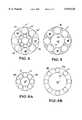
- FIGS. 4 and 5illustrate end sections of other embodiments of the invention.
- FIGS. 6A and 6Billustrate an embodiment capable of increased spatial resolution after entry in a body cavity.
- the present inventionis directed to a sparse aperture endoscope.
- Endoscopesare widely used in medicine and other applications for internal inspection purposes, and are particularly useful in laproscopic and other videoscopic medical procedures.
- the invention: 1) reduces the volume needed by the imaging part of the endoscope; 2) maintains resolution of a wide diameter optical system, but increases tool access; and 3) allows stereographic or interferometric processing for depth and perspective information/visualization.
- CCDEnd-mounted camera
- the endoscope of the present inventionimpacts the types of designs 1 and 2 above, and the size and weight constrains of all three prior designs.
- the present inventionaffects both size and weight because of a hollow core (or multiple channels) which can be produced with no reduction in image quality (spatial resolution).
- FIG. 1illustrates a typical prior art endoscope indicated at 10 and composed of an outer tube or member 11 and an inner tube or member 12 between which is a space or annulus 13 within which are positioned a plurality of fiber optic light pipes 14 for illumination, and with a single pupil imaging lens 15 in the inner member 12.
- the videois collected through the center lens 15 using relay optics down the length of the endoscope (sometimes over 30 cm) and the fiber optics 14 are connected to a light source for illumination only.
- the inner diameter, a, of inner member 12is also the diameter of lens 15 (which determines the spatial resolution of the system).
- the outer diameter, b, of the outer member 11determines the overall size of the endoscope 10.
- FIG. 2illustrates an embodiment of an endoscope made in accordance with the present invention, and components which correspond to the FIG. 1 prior art endoscope will be given corresponding reference numerals.
- the basic difference be the FIG. 2 and FIG. 1 endoscopesis that FIG. 2 utilizes a multi-pupil imaging system and has a central access channel for tools, etc.
- the endoscope of this inventiongenerally indicated at 10', utilizes, like the FIG. 1 endoscope, an outer tube or member 11', and inner tube or member 12', between which is a space or annulus 13' in which are positioned a plurality of fiber optic light pipes 14' for illumination purposes.
- FIG. 1illustrates an embodiment of an endoscope made in accordance with the present invention, and components which correspond to the FIG. 1 prior art endoscope will be given corresponding reference numerals.
- FIG. 2utilizes a multi-pupil imaging system and has a central access channel for tools, etc.
- the endoscope of this inventiongenerally indicated at 10'
- central tube or member 16to be positioned within inner member 12' and between which is defined a space or annulus 17 in which is located a plurality of pupil imaging lens 18 forming a multi-pupil imaging system.
- the interior of central tube or memberdefines a hollow access channel 19, through which tools, etc. may be passed.
- the videois collected through the multi-pupil array 18 using relay optics down the length of the endoscope or via fiber optic bundles.
- the fiber optics 14' in the annulus 13'are connected to a light source for illumination only.
- the diameter, ais the effective lens diameter (which determines the spatial resolution of the system and can be achieved with many different multi-pupil patterns).
- the outer diameter, bdetermines the overall size of the instrument.
- the inner diameter, cdetermines the size of the largest tool or instrument, etc., that can be manipulated through the endoscope via access channel 19.
- the multiple pupils or lens 18must be "combined" to form an image, just as in multi-aperture telescopes used in astronomy.
- FIG. 3schematically illustrates an optical system using the multi-pupil imaging system of FIG. 2.
- the optical transfer function for incoherent illuminationcovers the same spatial frequencies as a single aperture system.
- light from the scene of interest indicated by arrows 20is collected through multiple pupils 21 into an optical relay 22 (optics or fibers) to a combining optics 23 and onto an image plane 24 or for stereographic or interferometric array processing.
- the dimensions a, b, and c,are as described above with respect to FIG. 2.
- the tube or member 11may have an outer-diameter (O.D.) "b" of 1 to 20 mm, wall thickness of 0.1 to 1 mm, and be constructed of metal, plastic, rubber, or glass;
- the tube or member 12'may have an inner diameter (I.D.) "a", of 0.8 to 19.8 mm, wall thickness of 0.05 to 1 mm, and be constructed of metal, plastic, rubber, or glass;
- the tube or member 16may have an inner diameter (I.D.) "c” of 0.6 to 19.6 mm, wall thickness of 0.05 to 1 mm, and be constructed of metal, plastic, rubber, or glass; with the lens 18 having a diameter of 0.5 to 10 mm, and constructed of glass or plastic, with either a concave or convex surface or glass or plastic fiber optics filling the lens space.
- the fiber optic light pipes 14'may have a diameter of 0.01 to 0.5 mm.
- FIGS. 4 and 5illustrate an embodiment of the invention wherein the fiber optics are not located on the outside of the imaging lens as in FIG. 2.
- the fiber optic light pipes 14'are located within a central tube or member 16' and are mounted around a small center tube 25, with the lens 18' located around tube 16.
- the fiber optic light pipes 14'are located in the space or annulus 17' intermediate outer tube 11' and tube 16'; and are interspersed among the lens 18'.
- FIGS. 6A and 6Billustrate an embodiment, without the light pipes being shown, wherein the use of multiple lens allows movement thereof so that the outer diameter can be small upon entry and expanded once inside a body cavity, thereby providing an increased spatial resolution.
- the outside tube or member 26is constructed of an expandable material
- the central tube or member 27is constructed of a shape memory metal or polymer. Upon heating of the member 27 the member expands from the size shown in FIG. 6A to the size shown in FIG. 6B.
- Light pipes, not shown,can be located intermediate tubes or members 26 and 27, as in the FIG. 5 embodiment. As seen, when the member 26 is expanded as shown in FIG. 6B, such provides an increase in spatial resolution. Cooling of tube or member 26 allows the endoscope to contract and return to its smaller diameter as shown in FIG. 6A.
- the present inventionprovides an improved endoscope which enable expanded utility of such an instrument by the incorporation therein of a multi-pupil imaging system and an access channel for other tools, etc.
- the endoscope of this inventionprovides an improved tool for use, for example, in laproscopic and videoscopic medical procedures, as well as enabling an extended use in non-medical applications imposing difficult to see or difficult access conditions.
Landscapes
- Physics & Mathematics (AREA)
- Health & Medical Sciences (AREA)
- Life Sciences & Earth Sciences (AREA)
- Optics & Photonics (AREA)
- Surgery (AREA)
- Heart & Thoracic Surgery (AREA)
- Medical Informatics (AREA)
- Nuclear Medicine, Radiotherapy & Molecular Imaging (AREA)
- Pathology (AREA)
- Radiology & Medical Imaging (AREA)
- Astronomy & Astrophysics (AREA)
- Engineering & Computer Science (AREA)
- Biomedical Technology (AREA)
- Biophysics (AREA)
- Molecular Biology (AREA)
- General Physics & Mathematics (AREA)
- Animal Behavior & Ethology (AREA)
- General Health & Medical Sciences (AREA)
- Public Health (AREA)
- Veterinary Medicine (AREA)
- Endoscopes (AREA)
- Instruments For Viewing The Inside Of Hollow Bodies (AREA)
Abstract
Description
Claims (25)
Priority Applications (1)
| Application Number | Priority Date | Filing Date | Title |
|---|---|---|---|
| US08/877,714US5919128A (en) | 1997-06-18 | 1997-06-18 | Sparse aperture endoscope |
Applications Claiming Priority (1)
| Application Number | Priority Date | Filing Date | Title |
|---|---|---|---|
| US08/877,714US5919128A (en) | 1997-06-18 | 1997-06-18 | Sparse aperture endoscope |
Publications (1)
| Publication Number | Publication Date |
|---|---|
| US5919128Atrue US5919128A (en) | 1999-07-06 |
Family
ID=25370571
Family Applications (1)
| Application Number | Title | Priority Date | Filing Date |
|---|---|---|---|
| US08/877,714Expired - Fee RelatedUS5919128A (en) | 1997-06-18 | 1997-06-18 | Sparse aperture endoscope |
Country Status (1)
| Country | Link |
|---|---|
| US (1) | US5919128A (en) |
Cited By (45)
| Publication number | Priority date | Publication date | Assignee | Title |
|---|---|---|---|---|
| US20030045780A1 (en)* | 2001-09-06 | 2003-03-06 | Asahi Kogaku Kogyo Kasbushiki Kaisha | Probe and fluorescent diagnostic system |
| WO2002037160A3 (en)* | 2000-11-02 | 2003-04-24 | Keymed Medicals & Ind Equip | An apparatus for providing an image of a remote object accessible only through an aperture of finite diameter |
| US20030163030A1 (en)* | 2002-02-25 | 2003-08-28 | Arriaga Moises A. | Hollow endoscopy |
| US20040218291A1 (en)* | 2003-05-01 | 2004-11-04 | Eastman Kodak Company | Multiple aperture imaging system |
| US20040246604A1 (en)* | 2003-06-04 | 2004-12-09 | Eastman Kodak Company | High resolution image formation from a multiple aperture imaging system |
| US20050088752A1 (en)* | 2003-10-23 | 2005-04-28 | Eastman Kodak Company | Compact multiple aperture imaging array |
| EP1600804A1 (en)* | 2004-05-27 | 2005-11-30 | STM Medizintechnik Starnberg GmbH | Visual device for endoscopes |
| US20060161047A1 (en)* | 2003-09-19 | 2006-07-20 | Olympus Corporation | Endoscope |
| WO2006098146A1 (en) | 2005-03-15 | 2006-09-21 | Olympus Medical Systems Corp. | Insertion section for endoscope |
| US7170677B1 (en) | 2002-01-25 | 2007-01-30 | Everest Vit | Stereo-measurement borescope with 3-D viewing |
| US20070049803A1 (en)* | 2004-04-27 | 2007-03-01 | Hiroki Moriyama | Endoscope and endoscope system |
| US20070239056A1 (en)* | 2006-03-28 | 2007-10-11 | Kent Moore | System and method of predicting efficacy of tongue-base therapies |
| WO2007137059A2 (en) | 2006-05-17 | 2007-11-29 | Kent Moore | Stereovideoscope and method of using the same |
| US20080188873A1 (en)* | 2005-01-21 | 2008-08-07 | Giovanni Speziali | Thorascopic Heart Valve Repair Method and Apparatus |
| US20080269556A1 (en)* | 2007-04-02 | 2008-10-30 | Jagasia Ashok A | Endoscope with flexible tip |
| US20080287937A1 (en)* | 2007-05-15 | 2008-11-20 | Warsaw Orthopedic, Inc. | Surgical Instrument for Illuminating and Monitoring a Surgical Site |
| US20090012369A1 (en)* | 2005-09-30 | 2009-01-08 | Purdue Research Foundation | Endoscopic imaging device |
| US20090105751A1 (en)* | 2007-10-18 | 2009-04-23 | John Zentgraf | Minimally invasive repair of a valve leaflet in a beating heart |
| US20100033808A1 (en)* | 2008-08-08 | 2010-02-11 | Betchley Curtlan C | Optical system of light gathering using orthogonal compressions to form large diameter, shallow depth telescopes |
| US20110313249A1 (en)* | 2010-06-17 | 2011-12-22 | Viola Frank J | Endoluminal crawler |
| US20120215065A1 (en)* | 2011-02-17 | 2012-08-23 | Apurba Mukherjee | Endoscope with variable incident light and laser source platform |
| US8317689B1 (en)* | 1999-09-13 | 2012-11-27 | Visionscope Technologies Llc | Miniature endoscope system |
| US20130131445A1 (en)* | 2011-11-23 | 2013-05-23 | Boston Scientific Scimed, Inc. | Tissue and stone removal device and related methods of use |
| US20140009762A1 (en)* | 2012-06-21 | 2014-01-09 | Nikon Corporation | Measurement assembly with fiber optic array |
| US8728162B2 (en) | 2010-04-15 | 2014-05-20 | Osteomed, Llc | Direct lateral spine system instruments, implants and associated methods |
| US8992558B2 (en) | 2008-12-18 | 2015-03-31 | Osteomed, Llc | Lateral access system for the lumbar spine |
| US9044221B2 (en) | 2010-12-29 | 2015-06-02 | Neochord, Inc. | Exchangeable system for minimally invasive beating heart repair of heart valve leaflets |
| CN104887178A (en)* | 2015-05-26 | 2015-09-09 | 苏州四海通仪器有限公司 | Ocular endoscope and optical fiber assembly thereof |
| US20160070059A1 (en)* | 2013-05-01 | 2016-03-10 | Corning Incorporated | Random air line rod |
| US10028641B1 (en)* | 2012-05-18 | 2018-07-24 | John H. Prince | Combined ear, nose and throat inspection and operation instruments |
| CN110123248A (en)* | 2019-06-28 | 2019-08-16 | 邹晓辉 | Fujinon electronic video endoscope is used in a kind of imaging of medical image |
| US10588620B2 (en) | 2018-03-23 | 2020-03-17 | Neochord, Inc. | Device for suture attachment for minimally invasive heart valve repair |
| US10695178B2 (en) | 2011-06-01 | 2020-06-30 | Neochord, Inc. | Minimally invasive repair of heart valve leaflets |
| US10765517B2 (en) | 2015-10-01 | 2020-09-08 | Neochord, Inc. | Ringless web for repair of heart valves |
| US10966709B2 (en) | 2018-09-07 | 2021-04-06 | Neochord, Inc. | Device for suture attachment for minimally invasive heart valve repair |
| US11166709B2 (en) | 2016-08-23 | 2021-11-09 | Stryker European Operations Holdings Llc | Instrumentation and methods for the implantation of spinal implants |
| US11173030B2 (en) | 2018-05-09 | 2021-11-16 | Neochord, Inc. | Suture length adjustment for minimally invasive heart valve repair |
| US11191532B2 (en) | 2018-03-30 | 2021-12-07 | Stryker European Operations Holdings Llc | Lateral access retractor and core insertion |
| US11253360B2 (en) | 2018-05-09 | 2022-02-22 | Neochord, Inc. | Low profile tissue anchor for minimally invasive heart valve repair |
| US11376126B2 (en) | 2019-04-16 | 2022-07-05 | Neochord, Inc. | Transverse helical cardiac anchor for minimally invasive heart valve repair |
| US11564674B2 (en) | 2019-11-27 | 2023-01-31 | K2M, Inc. | Lateral access system and method of use |
| US11589989B2 (en) | 2017-03-31 | 2023-02-28 | Neochord, Inc. | Minimally invasive heart valve repair in a beating heart |
| US20250020905A1 (en)* | 2023-07-11 | 2025-01-16 | Tata Consultancy Services Limited | Optically sparse primary aperture for high spatial resolution imaging |
| US12208007B2 (en) | 2020-01-16 | 2025-01-28 | Neochord, Inc. | Helical cardiac anchors for minimally invasive heart valve repair |
| US12376873B2 (en) | 2019-08-27 | 2025-08-05 | Egan Design LLC | Surgical instrument for blunt dissection, dilation of incisions, and separation of adhesions |
Citations (9)
| Publication number | Priority date | Publication date | Assignee | Title |
|---|---|---|---|---|
| US4217891A (en)* | 1977-06-15 | 1980-08-19 | Carson Robert W | Novel arthroscope |
| EP0305170A2 (en)* | 1987-08-24 | 1989-03-01 | Allergan, Inc | Ophthalmic viewing instrument |
| US4919114A (en)* | 1988-01-14 | 1990-04-24 | Olympus Optical Co., Ltd. | Endoscope provided with flexible signal wires |
| US4924853A (en)* | 1989-05-22 | 1990-05-15 | Medical Dimensions, Inc. | Stereoscopic medical viewing device |
| US5166787A (en)* | 1989-06-28 | 1992-11-24 | Karl Storz Gmbh & Co. | Endoscope having provision for repositioning a video sensor to a location which does not provide the same cross-sectionally viewed relationship with the distal end |
| US5305121A (en)* | 1992-06-08 | 1994-04-19 | Origin Medsystems, Inc. | Stereoscopic endoscope system |
| US5437626A (en)* | 1992-11-30 | 1995-08-01 | Neuro Navigational Corporation | Shunt with internal neuroendoscope |
| US5603687A (en)* | 1992-10-28 | 1997-02-18 | Oktas General Partnership | Asymmetric stereo-optic endoscope |
| US5743847A (en)* | 1995-01-13 | 1998-04-28 | Olympus Optical Co., Ltd. | Stereoscopic endoscope having image transmitting optical-system and pupil dividing unit that are axially movable with respect to each other |
- 1997
- 1997-06-18USUS08/877,714patent/US5919128A/ennot_activeExpired - Fee Related
Patent Citations (9)
| Publication number | Priority date | Publication date | Assignee | Title |
|---|---|---|---|---|
| US4217891A (en)* | 1977-06-15 | 1980-08-19 | Carson Robert W | Novel arthroscope |
| EP0305170A2 (en)* | 1987-08-24 | 1989-03-01 | Allergan, Inc | Ophthalmic viewing instrument |
| US4919114A (en)* | 1988-01-14 | 1990-04-24 | Olympus Optical Co., Ltd. | Endoscope provided with flexible signal wires |
| US4924853A (en)* | 1989-05-22 | 1990-05-15 | Medical Dimensions, Inc. | Stereoscopic medical viewing device |
| US5166787A (en)* | 1989-06-28 | 1992-11-24 | Karl Storz Gmbh & Co. | Endoscope having provision for repositioning a video sensor to a location which does not provide the same cross-sectionally viewed relationship with the distal end |
| US5305121A (en)* | 1992-06-08 | 1994-04-19 | Origin Medsystems, Inc. | Stereoscopic endoscope system |
| US5603687A (en)* | 1992-10-28 | 1997-02-18 | Oktas General Partnership | Asymmetric stereo-optic endoscope |
| US5437626A (en)* | 1992-11-30 | 1995-08-01 | Neuro Navigational Corporation | Shunt with internal neuroendoscope |
| US5743847A (en)* | 1995-01-13 | 1998-04-28 | Olympus Optical Co., Ltd. | Stereoscopic endoscope having image transmitting optical-system and pupil dividing unit that are axially movable with respect to each other |
Cited By (95)
| Publication number | Priority date | Publication date | Assignee | Title |
|---|---|---|---|---|
| US8317689B1 (en)* | 1999-09-13 | 2012-11-27 | Visionscope Technologies Llc | Miniature endoscope system |
| US20130046142A1 (en)* | 1999-09-13 | 2013-02-21 | Paul Remijan | Miniature endoscope system |
| WO2002037160A3 (en)* | 2000-11-02 | 2003-04-24 | Keymed Medicals & Ind Equip | An apparatus for providing an image of a remote object accessible only through an aperture of finite diameter |
| US20030179448A1 (en)* | 2000-11-02 | 2003-09-25 | Andrew Ramsbottom | Apparatus for providing an image of a remote object accessible only through an aperture of finite diameter |
| JP2003070722A (en)* | 2001-09-06 | 2003-03-11 | Pentax Corp | Probe and fluorescence diagnostic system |
| US20030045780A1 (en)* | 2001-09-06 | 2003-03-06 | Asahi Kogaku Kogyo Kasbushiki Kaisha | Probe and fluorescent diagnostic system |
| US7564626B2 (en) | 2002-01-25 | 2009-07-21 | Ge Inspection Technologies Lp | Stereo-measurement borescope with 3-D viewing |
| US7170677B1 (en) | 2002-01-25 | 2007-01-30 | Everest Vit | Stereo-measurement borescope with 3-D viewing |
| WO2003072163A3 (en)* | 2002-02-25 | 2004-02-19 | Moises A Arriaga | Hollow endoscopy |
| US20030163030A1 (en)* | 2002-02-25 | 2003-08-28 | Arriaga Moises A. | Hollow endoscopy |
| US6943946B2 (en) | 2003-05-01 | 2005-09-13 | Itt Manufacturing Enterprises, Inc. | Multiple aperture imaging system |
| US20040218291A1 (en)* | 2003-05-01 | 2004-11-04 | Eastman Kodak Company | Multiple aperture imaging system |
| US20040246604A1 (en)* | 2003-06-04 | 2004-12-09 | Eastman Kodak Company | High resolution image formation from a multiple aperture imaging system |
| US6880943B2 (en) | 2003-06-04 | 2005-04-19 | Itt Manufacturing Enterprises, Inc. | High resolution image formation from a multiple aperture imaging system |
| US20060161047A1 (en)* | 2003-09-19 | 2006-07-20 | Olympus Corporation | Endoscope |
| US20050088752A1 (en)* | 2003-10-23 | 2005-04-28 | Eastman Kodak Company | Compact multiple aperture imaging array |
| US6924935B2 (en) | 2003-10-23 | 2005-08-02 | Itt Manufacturing Enterprises Inc. | Compact multiple aperture imaging array |
| US8137264B2 (en)* | 2004-04-27 | 2012-03-20 | Olympus Corporation | Endoscope system having two endoscopes with different viewing angles |
| US20070049803A1 (en)* | 2004-04-27 | 2007-03-01 | Hiroki Moriyama | Endoscope and endoscope system |
| EP1600804A1 (en)* | 2004-05-27 | 2005-11-30 | STM Medizintechnik Starnberg GmbH | Visual device for endoscopes |
| US9700300B2 (en) | 2005-01-21 | 2017-07-11 | Mayo Foundation For Medical Education And Research | Thorascopic heart valve repair apparatus |
| US8968338B2 (en) | 2005-01-21 | 2015-03-03 | Mayo Foundation For Medical Education And Research | Thorascopic heart valve repair method and apparatus |
| US20080188873A1 (en)* | 2005-01-21 | 2008-08-07 | Giovanni Speziali | Thorascopic Heart Valve Repair Method and Apparatus |
| US8465500B2 (en) | 2005-01-21 | 2013-06-18 | Mayo Foundation For Medical Education And Research | Thorascopic heart valve repair method and apparatus |
| US11534156B2 (en) | 2005-01-21 | 2022-12-27 | Mayo Foundation For Medical Education And Research | Thorascopic heart valve repair method and apparatus |
| US9364213B2 (en) | 2005-01-21 | 2016-06-14 | Mayo Foundation For Medical Education And Research | Thorascopic heart valve repair method |
| US10582924B2 (en) | 2005-01-21 | 2020-03-10 | Mayo Foundation For Medical Education And Research | Thorascopic heart valve repair method |
| US20080167529A1 (en)* | 2005-03-15 | 2008-07-10 | Takashi Otawara | Endoscope Insertion Portion |
| EP1859723A4 (en)* | 2005-03-15 | 2010-02-10 | Olympus Medical Systems Corp | SECTION D INSERTION FOR ENDOSCOPE |
| US7998064B2 (en) | 2005-03-15 | 2011-08-16 | Olympus Medical Systems Corp. | Endoscope insertion portion |
| WO2006098146A1 (en) | 2005-03-15 | 2006-09-21 | Olympus Medical Systems Corp. | Insertion section for endoscope |
| US20090012369A1 (en)* | 2005-09-30 | 2009-01-08 | Purdue Research Foundation | Endoscopic imaging device |
| US8777846B2 (en) | 2005-09-30 | 2014-07-15 | Purdue Research Foundation | Endoscopic imaging device |
| US8251896B2 (en)* | 2005-09-30 | 2012-08-28 | Purdue Research Foundation | Endoscopic imaging device |
| US7697968B2 (en) | 2006-03-28 | 2010-04-13 | Kent Moore | System and method of predicting efficacy of tongue-base therapies |
| US20070239056A1 (en)* | 2006-03-28 | 2007-10-11 | Kent Moore | System and method of predicting efficacy of tongue-base therapies |
| US20090198100A1 (en)* | 2006-05-17 | 2009-08-06 | Kent Moore | Stereovideoscope and method of using the same |
| WO2007137059A3 (en)* | 2006-05-17 | 2008-03-20 | Kent Moore | Stereovideoscope and method of using the same |
| WO2007137059A2 (en) | 2006-05-17 | 2007-11-29 | Kent Moore | Stereovideoscope and method of using the same |
| US8162820B2 (en) | 2006-05-17 | 2012-04-24 | Kent Moore | Stereovideoscope and method of using the same |
| US20080269556A1 (en)* | 2007-04-02 | 2008-10-30 | Jagasia Ashok A | Endoscope with flexible tip |
| US20080287937A1 (en)* | 2007-05-15 | 2008-11-20 | Warsaw Orthopedic, Inc. | Surgical Instrument for Illuminating and Monitoring a Surgical Site |
| US9192374B2 (en) | 2007-10-18 | 2015-11-24 | Neochord, Inc. | Minimally invasive repair of a valve leaflet in a beating heart |
| US20090105751A1 (en)* | 2007-10-18 | 2009-04-23 | John Zentgraf | Minimally invasive repair of a valve leaflet in a beating heart |
| US12426874B2 (en) | 2007-10-18 | 2025-09-30 | Neochord, Inc. | Minimally invasive repair of a valve leaflet in a beating heart |
| US10507018B2 (en) | 2007-10-18 | 2019-12-17 | Neochord, Inc. | Minimally invasive repair of a valve leaflet in a beating heart |
| US8758393B2 (en) | 2007-10-18 | 2014-06-24 | Neochord, Inc. | Minimally invasive repair of a valve leaflet in a beating heart |
| US11419602B2 (en) | 2007-10-18 | 2022-08-23 | Neochord, Inc. | Minimally invasive repair of a valve leaflet in a beating heart |
| US20100033808A1 (en)* | 2008-08-08 | 2010-02-11 | Betchley Curtlan C | Optical system of light gathering using orthogonal compressions to form large diameter, shallow depth telescopes |
| US8085466B2 (en) | 2008-08-08 | 2011-12-27 | The Boeing Company | Optical system of light gathering using orthogonal compressions to form large diameter, shallow depth telescopes |
| US10687797B2 (en) | 2008-12-18 | 2020-06-23 | Howmedica Osteonics Corp. | Lateral access system for the lumbar spine |
| US8992558B2 (en) | 2008-12-18 | 2015-03-31 | Osteomed, Llc | Lateral access system for the lumbar spine |
| US11925342B2 (en) | 2008-12-18 | 2024-03-12 | Howmedica Osteonics Corp. | Lateral access system for the lumbar spine |
| US8728162B2 (en) | 2010-04-15 | 2014-05-20 | Osteomed, Llc | Direct lateral spine system instruments, implants and associated methods |
| US9326663B2 (en)* | 2010-06-17 | 2016-05-03 | Covidien Lp | Endoluminal crawler |
| US20110313249A1 (en)* | 2010-06-17 | 2011-12-22 | Viola Frank J | Endoluminal crawler |
| US9833129B2 (en) | 2010-06-17 | 2017-12-05 | Covidien Lp | Endoluminal crawler |
| US9044221B2 (en) | 2010-12-29 | 2015-06-02 | Neochord, Inc. | Exchangeable system for minimally invasive beating heart repair of heart valve leaflets |
| US10080659B1 (en) | 2010-12-29 | 2018-09-25 | Neochord, Inc. | Devices and methods for minimally invasive repair of heart valves |
| US10130474B2 (en) | 2010-12-29 | 2018-11-20 | Neochord, Inc. | Exchangeable system for minimally invasive beating heart repair of heart valve leaflets |
| US20120215065A1 (en)* | 2011-02-17 | 2012-08-23 | Apurba Mukherjee | Endoscope with variable incident light and laser source platform |
| US8323181B2 (en)* | 2011-02-17 | 2012-12-04 | Apurba Mukherjee | Endoscope with variable incident light and laser source platform |
| US10695178B2 (en) | 2011-06-01 | 2020-06-30 | Neochord, Inc. | Minimally invasive repair of heart valve leaflets |
| US11974920B2 (en) | 2011-06-01 | 2024-05-07 | Neochord, Inc. | Minimally invasive repair of heart valve leaflets |
| US9393033B2 (en)* | 2011-11-23 | 2016-07-19 | Boston Scientific Scimed, Inc. | Tissue and stone removal device and related methods of use |
| US10463432B2 (en) | 2011-11-23 | 2019-11-05 | Boston Scientific Scimed, Inc. | Tissue and stone removal device and related methods of use |
| US10004560B2 (en) | 2011-11-23 | 2018-06-26 | Boston Scientific Scimed, Inc. | Tissue and stone removal device and related methods of use |
| US20130131445A1 (en)* | 2011-11-23 | 2013-05-23 | Boston Scientific Scimed, Inc. | Tissue and stone removal device and related methods of use |
| US10028641B1 (en)* | 2012-05-18 | 2018-07-24 | John H. Prince | Combined ear, nose and throat inspection and operation instruments |
| US20140009762A1 (en)* | 2012-06-21 | 2014-01-09 | Nikon Corporation | Measurement assembly with fiber optic array |
| US20160070059A1 (en)* | 2013-05-01 | 2016-03-10 | Corning Incorporated | Random air line rod |
| CN104887178A (en)* | 2015-05-26 | 2015-09-09 | 苏州四海通仪器有限公司 | Ocular endoscope and optical fiber assembly thereof |
| US10765517B2 (en) | 2015-10-01 | 2020-09-08 | Neochord, Inc. | Ringless web for repair of heart valves |
| US11484409B2 (en) | 2015-10-01 | 2022-11-01 | Neochord, Inc. | Ringless web for repair of heart valves |
| US12133643B2 (en) | 2016-08-23 | 2024-11-05 | Stryker European Operations Holdings Llc | Instrumentation and methods for the implantation of spinal implants |
| US11166709B2 (en) | 2016-08-23 | 2021-11-09 | Stryker European Operations Holdings Llc | Instrumentation and methods for the implantation of spinal implants |
| US12208009B2 (en) | 2017-03-31 | 2025-01-28 | Neochord, Inc. | Minimally invasive heart valve repair in a beating heart |
| US11589989B2 (en) | 2017-03-31 | 2023-02-28 | Neochord, Inc. | Minimally invasive heart valve repair in a beating heart |
| US10588620B2 (en) | 2018-03-23 | 2020-03-17 | Neochord, Inc. | Device for suture attachment for minimally invasive heart valve repair |
| US11612389B2 (en) | 2018-03-23 | 2023-03-28 | Neochord, Inc. | Device for suture attachment for minimally invasive heart valve repair |
| US12310577B2 (en) | 2018-03-23 | 2025-05-27 | Neochord, Inc. | Device for suture attachment for minimally invasive heart valve repair |
| US11911016B2 (en) | 2018-03-30 | 2024-02-27 | Stryker European Operations Holdings Llc | Lateral access retractor and core insertion |
| US11191532B2 (en) | 2018-03-30 | 2021-12-07 | Stryker European Operations Holdings Llc | Lateral access retractor and core insertion |
| US11173030B2 (en) | 2018-05-09 | 2021-11-16 | Neochord, Inc. | Suture length adjustment for minimally invasive heart valve repair |
| US11957584B2 (en) | 2018-05-09 | 2024-04-16 | Neochord, Inc. | Suture length adjustment for minimally invasive heart valve repair |
| US11253360B2 (en) | 2018-05-09 | 2022-02-22 | Neochord, Inc. | Low profile tissue anchor for minimally invasive heart valve repair |
| US10966709B2 (en) | 2018-09-07 | 2021-04-06 | Neochord, Inc. | Device for suture attachment for minimally invasive heart valve repair |
| US12137897B2 (en) | 2018-09-07 | 2024-11-12 | Neochord, Inc. | Device for suture attachment for minimally invasive heart valve repair |
| US11376126B2 (en) | 2019-04-16 | 2022-07-05 | Neochord, Inc. | Transverse helical cardiac anchor for minimally invasive heart valve repair |
| US11918468B2 (en) | 2019-04-16 | 2024-03-05 | Neochord, Inc. | Transverse helical cardiac anchor for minimally invasive heart valve repair |
| CN110123248A (en)* | 2019-06-28 | 2019-08-16 | 邹晓辉 | Fujinon electronic video endoscope is used in a kind of imaging of medical image |
| US12376873B2 (en) | 2019-08-27 | 2025-08-05 | Egan Design LLC | Surgical instrument for blunt dissection, dilation of incisions, and separation of adhesions |
| US11564674B2 (en) | 2019-11-27 | 2023-01-31 | K2M, Inc. | Lateral access system and method of use |
| US12208007B2 (en) | 2020-01-16 | 2025-01-28 | Neochord, Inc. | Helical cardiac anchors for minimally invasive heart valve repair |
| US20250020905A1 (en)* | 2023-07-11 | 2025-01-16 | Tata Consultancy Services Limited | Optically sparse primary aperture for high spatial resolution imaging |
Similar Documents
| Publication | Publication Date | Title |
|---|---|---|
| US5919128A (en) | Sparse aperture endoscope | |
| US20230131558A1 (en) | Pannable Endoscope | |
| US4964710A (en) | Disposable rigid endoscope | |
| US5603687A (en) | Asymmetric stereo-optic endoscope | |
| US5976076A (en) | Stereo laparoscope with synchronized optics | |
| US5630784A (en) | Method of making and using a rigid endoscope having a modified high refractive index tunnel rod | |
| KR100556232B1 (en) | Adjustable binocular laparoscopy | |
| EP0646821B1 (en) | Optical system for endoscope | |
| US20030163030A1 (en) | Hollow endoscopy | |
| JP2001520399A (en) | Sapphire objective lens system | |
| JP2007503277A (en) | System, apparatus and method for observing hard-to-see parts of a cavity | |
| WO1996025874A1 (en) | Stereo laparoscope appratus and method | |
| WO1998011815A1 (en) | High resolution, wide field of view endoscopic viewing system | |
| CN110840386A (en) | Visible and near-infrared fluorescence 3D co-imaging endoscopy system based on single detector | |
| US20140316199A1 (en) | Arthroscopic system | |
| US5412504A (en) | Optical system for an endoscope | |
| US5263110A (en) | Imaging endoscope and endoscopic method employing phase conjugate imaging techniques | |
| JPH10507105A (en) | Endoscope | |
| RU2762784C2 (en) | Relay optics for rigid endoscope and endoscope | |
| EP1519675A1 (en) | Optical device for endoscope | |
| CN104434006A (en) | Double-channel endoscope | |
| KR102006859B1 (en) | Endoscopic imaging catheter | |
| JP3675919B2 (en) | Stereoscope | |
| CN115486794B (en) | Guide wire endoscope | |
| CN213787280U (en) | Miniature ultra-wide-angle endoscope lens matched with OV6930 chip |
Legal Events
| Date | Code | Title | Description |
|---|---|---|---|
| AS | Assignment | Owner name:REGENTS OF THE UNIVERSITY OF CALIFORNIA, THE, CALI Free format text:ASSIGNMENT OF ASSIGNORS INTEREST;ASSIGNOR:FITCH, JOSEPH P.;REEL/FRAME:008641/0217 Effective date:19970529 | |
| AS | Assignment | Owner name:CALIFORNIA, UNIVERSITY OF, REGENTS OF THE, THE, CA Free format text:ASSIGNMENT OF ASSIGNORS INTEREST;ASSIGNOR:FITCH, JOSEPH P.;REEL/FRAME:009787/0040 Effective date:19970524 | |
| REMI | Maintenance fee reminder mailed | ||
| FPAY | Fee payment | Year of fee payment:4 | |
| SULP | Surcharge for late payment | ||
| AS | Assignment | Owner name:ENERGY, U.S. DEPARTMENT OF, DISTRICT OF COLUMBIA Free format text:CONFIRMATORY LICENSE;ASSIGNOR:REGENTS OF THE UNIVERSITY OF CALIFORNIA, THE;REEL/FRAME:014027/0647 Effective date:19980716 | |
| REMI | Maintenance fee reminder mailed | ||
| FPAY | Fee payment | Year of fee payment:8 | |
| SULP | Surcharge for late payment | Year of fee payment:7 | |
| AS | Assignment | Owner name:LAWRENCE LIVERMORE NATIONAL SECURITY LLC, CALIFORN Free format text:ASSIGNMENT OF ASSIGNORS INTEREST;ASSIGNOR:THE REGENTS OF THE UNIVERSITY OF CALIFORNIA;REEL/FRAME:021217/0050 Effective date:20080623 | |
| REMI | Maintenance fee reminder mailed | ||
| LAPS | Lapse for failure to pay maintenance fees | ||
| STCH | Information on status: patent discontinuation | Free format text:PATENT EXPIRED DUE TO NONPAYMENT OF MAINTENANCE FEES UNDER 37 CFR 1.362 | |
| FP | Lapsed due to failure to pay maintenance fee | Effective date:20110706 |