US5918380A - Time-of-use and demand metering in conditions of power outage - Google Patents
Time-of-use and demand metering in conditions of power outageDownload PDFInfo
- Publication number
- US5918380A US5918380AUS08/987,355US98735597AUS5918380AUS 5918380 AUS5918380 AUS 5918380AUS 98735597 AUS98735597 AUS 98735597AUS 5918380 AUS5918380 AUS 5918380A
- Authority
- US
- United States
- Prior art keywords
- time
- consumption
- interval
- power
- power outage
- Prior art date
- Legal status (The legal status is an assumption and is not a legal conclusion. Google has not performed a legal analysis and makes no representation as to the accuracy of the status listed.)
- Expired - Lifetime
Links
- 230000005540biological transmissionEffects0.000claimsabstractdescription10
- 230000006870functionEffects0.000claimsdescription10
- 238000004891communicationMethods0.000claimsdescription4
- 238000013459approachMethods0.000description12
- 238000005096rolling processMethods0.000description8
- 238000000034methodMethods0.000description7
- 238000012544monitoring processMethods0.000description6
- 238000004364calculation methodMethods0.000description5
- 230000004913activationEffects0.000description4
- 239000012190activatorSubstances0.000description4
- 230000007704transitionEffects0.000description4
- 230000008901benefitEffects0.000description3
- 238000013461designMethods0.000description2
- 230000008569processEffects0.000description2
- 230000001360synchronised effectEffects0.000description2
- 239000002131composite materialSubstances0.000description1
- 238000010276constructionMethods0.000description1
- 238000010586diagramMethods0.000description1
- 230000004069differentiationEffects0.000description1
- 230000000694effectsEffects0.000description1
- 230000005611electricityEffects0.000description1
- 238000005516engineering processMethods0.000description1
- 230000002708enhancing effectEffects0.000description1
- 238000009472formulationMethods0.000description1
- 239000000203mixtureSubstances0.000description1
- 238000012552reviewMethods0.000description1
- 239000007787solidSubstances0.000description1
Images


Classifications
- G—PHYSICS
- G01—MEASURING; TESTING
- G01R—MEASURING ELECTRIC VARIABLES; MEASURING MAGNETIC VARIABLES
- G01R21/00—Arrangements for measuring electric power or power factor
- G01R21/133—Arrangements for measuring electric power or power factor by using digital technique
- G—PHYSICS
- G01—MEASURING; TESTING
- G01D—MEASURING NOT SPECIALLY ADAPTED FOR A SPECIFIC VARIABLE; ARRANGEMENTS FOR MEASURING TWO OR MORE VARIABLES NOT COVERED IN A SINGLE OTHER SUBCLASS; TARIFF METERING APPARATUS; MEASURING OR TESTING NOT OTHERWISE PROVIDED FOR
- G01D4/00—Tariff metering apparatus
- G01D4/002—Remote reading of utility meters
- G01D4/006—Remote reading of utility meters to a non-fixed location, i.e. mobile location
- Y—GENERAL TAGGING OF NEW TECHNOLOGICAL DEVELOPMENTS; GENERAL TAGGING OF CROSS-SECTIONAL TECHNOLOGIES SPANNING OVER SEVERAL SECTIONS OF THE IPC; TECHNICAL SUBJECTS COVERED BY FORMER USPC CROSS-REFERENCE ART COLLECTIONS [XRACs] AND DIGESTS
- Y02—TECHNOLOGIES OR APPLICATIONS FOR MITIGATION OR ADAPTATION AGAINST CLIMATE CHANGE
- Y02B—CLIMATE CHANGE MITIGATION TECHNOLOGIES RELATED TO BUILDINGS, e.g. HOUSING, HOUSE APPLIANCES OR RELATED END-USER APPLICATIONS
- Y02B90/00—Enabling technologies or technologies with a potential or indirect contribution to GHG emissions mitigation
- Y02B90/20—Smart grids as enabling technology in buildings sector
- Y—GENERAL TAGGING OF NEW TECHNOLOGICAL DEVELOPMENTS; GENERAL TAGGING OF CROSS-SECTIONAL TECHNOLOGIES SPANNING OVER SEVERAL SECTIONS OF THE IPC; TECHNICAL SUBJECTS COVERED BY FORMER USPC CROSS-REFERENCE ART COLLECTIONS [XRACs] AND DIGESTS
- Y04—INFORMATION OR COMMUNICATION TECHNOLOGIES HAVING AN IMPACT ON OTHER TECHNOLOGY AREAS
- Y04S—SYSTEMS INTEGRATING TECHNOLOGIES RELATED TO POWER NETWORK OPERATION, COMMUNICATION OR INFORMATION TECHNOLOGIES FOR IMPROVING THE ELECTRICAL POWER GENERATION, TRANSMISSION, DISTRIBUTION, MANAGEMENT OR USAGE, i.e. SMART GRIDS
- Y04S20/00—Management or operation of end-user stationary applications or the last stages of power distribution; Controlling, monitoring or operating thereof
- Y04S20/30—Smart metering, e.g. specially adapted for remote reading
Definitions
- the present inventionrelates to the metering of the consumption of electrical energy. More particularly, the present invention relates to providing advanced metering functions when power is temporarily lost at the meter.
- RFradio frequency
- Kilowatt demandis generally defined as the kilowatt load averaged over a specified interval of time.
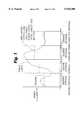
- the meaning of demandcan be understood from FIG. 1, which shows an example power curve over time. In any one of the time intervals shown, the area under the dotted line ⁇ demand ⁇ is exactly equal to the area under the power curve. Since energy is the product of time and power, either of these two areas represents the energy consumed in the demand interval.
- the equivalence of the two areasshows that the demand for the interval is that value of power which, if held constant over the interval, will account for the same consumption of energy as the real power. Demand can then be defined as the average of the real power over the interval.”
- the horizontal axisis time and the vertical axis is units of power in kilowatts (kW).
- Typical electric metersrecord consumption in units of kilowatt-hours (kWh), which is an energy value. For instance, in a first case an electrical meter would register one kWh consumption if one kW were used constantly for one hour. Similarly, in a second case the meter would show one kWh consumption at the end of an hour if two kW were used constantly for the first half hour with no energy used in a second half hour. Finally, in a third case the meter would also show one kWh consumption at the end of an hour if twelve kW were used constantly for the initial five minutes of the one hour interval and no energy was used in the remaining 55 minutes. FIG.
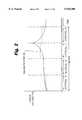
- Demandis the area under the dotted line in each of the demand intervals.
- the area under the dotted lineequals the area under the power curve equals total energy for the interval.
- Demand then for each of the four demand intervalsequals the average power over the individual demand intervals.
- Table 1The aforementioned three cases are depicted in Table 1.
- Table 1The bottom entry in Table 1, labeled "Electric Meter Value Registered at End of Time Period", shows the increase in consumption which would be recorded on the electric meter at the end of each hour for each of the three cases presented. All of the three cases are shown to have the same consumption. From a pure consumption point of view all cases would then have the same electric bill for the one hour demand interval.
- Block demandis a frequently used form of demand billing. Referring to FIG. 2, time is displayed on the horizontal axis and power is displayed on the vertical axis. As displayed on the horizontal axis there are four intervals, A-D, that comprise a single block. Block demand calculates demand over the intervals A-D comprising the block. Consumption is recorded over the interval and divided by a time period, in hours, that the interval comprises. Repeating this for all the intervals in a block would allow billing based on the average demand over the block. Most often, however, the maximum demand is billed for the entire period of the block. FIG. 2 illustrates the demand for each interval as being indicated by the area under the dashed line. In practice, the maximum demand, depicted in interval C, is the demand that would be billed to the customer over the entire period comprising the block.
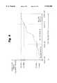
- Rolling demandis another frequently used form of demand billing.
- Rolling demandmay be thought of as a sliding window of block demands.
- the time scale on the horizontal axisis still divided into individual intervals.
- the time scaleis further divided into sub-intervals, as depicted.
- the calculationis performed by adding the consumption for a set number of sub-intervals and then dividing by the time period, in hours, of the composite interval.
- Rolling demandpermits greater accuracy in demand billing.
- Total demand, average demand, maximum demand, and average maximum demand during a full intervalare all types of demand billing that are supported by calculating rolling demands. Once the rolling demand is known, any of the aforementioned types of demand billing may be used.
- Table 2presents the same three cases as previously presented with respect to Table 1. Assuming that the demand sub-interval for billing is five minutes, the demand over the total hour billing period would be calculated for each interval with each interval being comprised of three successive five minute periods. Over the whole billing period, all demand value from these intervals will be compared with the largest one being used for billing purposes. As depicted in FIG. 3, the maximum demand is calculated in the eighth interval from the beginning of the one hour time period.
- each of the twelve minute sub-intervalswould have the same demand value of 12 kW. Accordingly, the maximum demand for this case is 12 kW and the billing would be for 12 kWh.
- Table 2compares the different billing approaches. From a straight consumption perspective, all three cases are billed the same as indicted in Table 1. However, when the demand is billed, it is clear that a maximum demand billing will distinguish the cases drawing heavy loads for relatively short periods. It shows the advantages to the electric utility for demand metering. The utilities typically desire this billing method since the cost of supplying energy to a customer depends on the needed capacity of the utility. This cost translates directly into demand.
- Time-of-use meteringrecords consumption during selected periods of time taken from a larger period of time. Typically the larger period of time is a day or a week. Rather than providing the utility with the capability to only charge the user for the energy used, rates structured on time-of-use information can account for when the energy is used. This allows utilities to charge premiums for energy drawn during peak periods (typically during the daytime) and provide lower rates for energy drawn during low usage periods (typically during nighttime).
- Rate Athe low rate
- Rate Bthe high rate
- Rate Athe low rate
- Rate Bthe high rate
- the bill for this daywill be based on 10 kWh at rate A, 20 kwh at rate B.
- An RF based systemtypically includes a meter transmitter or encoding device located at the site of the meter and a remote receiver or reading device.
- the consumption message transmitted from the encoding devicedoes not contain a time reference.
- a time referenceis, however, typically stamped to the consumption message by the reading device as it is read by the reading device. This assures that the consumption sent was the consumption at the time of transmission and that the read device clock is accurate and reliable. It has been shown that an RF system will occasionally miss reading a transmission of a consumption message. System design allows for only a certain percentage of message read reliability, which is always less than 100%.
- a typical compensation approachis to transmit multiple consumption messages at a time.
- This compensation approachtypically transmits the last N consumptions recorded at the meter in predefined t.sub. ⁇ intervals.
- the reading devicethen decodes this message to have an accurate consumption history over the last N predefined t.sub. ⁇ intervals. Therefore, the reading device only needs to decode one out of every N transmissions in order to receive an accurate consumption message.
- the aforementioned compensation approachis typically designed so that the desired reliability is achieved under normal operating conditions.
- the compensation approachadequately supports the advanced metering functions of time-of-use and demand billing.
- the encoding deviceis powered by the power at the meter that is being metered. Any counter in the encoding device shuts down when power is lost during a power outage.
- the consumption information transmitted by the encoding devicehas no reliable time reference with it.
- the reading devicedetects and decodes the N consumption values, it can only accurately time stamp the most recent value. All the previous N-1 values cannot be reliably time stamped because, if a power outage has occurred, it is not known when the power outage occurred or the duration of the power outage. This greatly degrades the ability of such a system to support both time-of-use and demand billing in the presence of a power outage. Accordingly, there is a need in the industry for an RF based encoding device and associated receiving device that have the ability to support both time-of-use and demand billing, even in the presence of power outages observed at the meter.
- the present inventionhas the capability of maintaining the time reference needed to support both demand and time-of-use billing by an electric utility with an RF based system. Since there are many millions of electrical meters currently in existence, any device that must be added to such a meter must have very low cost. Accordingly, the present invention is capable of supporting the advanced metering demanded by utilities with inexpensive component building blocks. Such building blocks include a microprocessor, an EE Prom, and simple power supplies.
- the present inventionhas the ability to accurately time stamp, without ambiguity, all consumption data in a period in which a single power outage is experienced. Further, the present invention has the ability to accurately time stamp, without ambiguity, some consumption data in a period in which multiple power outages occur.
- the present inventionperforms these functions with no need to synchronize clocks in the encoder device in the read device and without the need to provide backup battery power at the meter to power a clock in the event of a power outage.
- the present inventionhas the ability to maintain power consumption history, as well as current consumption, through periods in which a power outage occurs.
- a metering system for metering the consumption of electrical energy to provide time-of-use and demand metering in the presence of at least one power outage eventincludes an encoder device for transmitting a radio frequency (RF) signal and a receiver device for receiving the radio frequency signal transmitted by the encoder device.
- the encoder devicehas apparatus for sensing electrical power consumption and for sensing a power outage. Additionally, the encoder device has apparatus for periodically generating an encoded RF signal for transmission by the encoder device.
- the signalhas a plurality of discrete components, each of the components being related to electrical power consumption over a selected interval of time.
- the signalfurther has a power outage flag associated with each discrete component, the flag being set for any interval of time during which a power outage is sensed.
- a meter counter for incrementally increasing a count as a function of timeis included.
- the meter counteris powered by the electrical power being metered.
- the receiver devicehas a decoder that is communicatively coupled to the encoder device for decoding the encoded RF signal received from the encoder device.
- a receiver counter for incrementally increasing a count as a function of timeis asynchronous with respect to the meter counter.
- FIG. 1is a graphic representation of power consumption with power represented on the ordinate and time represented on the abscissa;
- FIG. 2is a graphic representation of power consumption with power represented on the ordinate and time represented on the abscissa depicting maximum demand billing over a block of time;
- FIG. 3is a graphic representation of power consumption with power on the ordinate and time on the abscissa depicting a rolling demand type billing calculation
- FIG. 4is a graphic representation of power consumption with power on the ordinate and time on the abscissa depicting a time-of-use billing over a one day billing cycle;
- FIG. 5is a schematic representation of the automatic/remote RF instrument monitoring system of the present invention.
- FIG. 6is a graphic representation of the effect of a power outage on an interval in which power consumption data is recorded
- FIG. 7is a representation of a buffer assigned in the nonvolatile memory of the encoder microprocessor
- FIG. 8depicts a pointer in the encoder microprocessor that indicates the encoded consumption value which occurred at the most recent interval
- FIG. 9depicts the pointer of FIG. 8 incremented by one bin
- FIG. 10is a graphic representation having count value on the ordinate and time on the abscissa depicting the different slopes of the encoder counter and the interrogate/receiver counter;
- FIG. 11depicts the impact of a power outage on the counters depicted in FIG. 10;
- FIG. 12is a graph of count value on the ordinate and time on the abscissa depicting a single power outage occurring in the ninth sub-interval of a consumption interval.
- FIG. 13is a graph of count value on the ordinate and time on the abscissa depicting two power outages in a single interval.
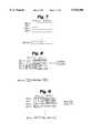
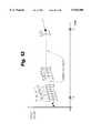
- a communication system that is more particularly an automatic/remote RF instrument monitoring systemis illustrated generally at 10 in FIG. 5.
- automatic/remote instrument monitoring system 10is adapted for use with a plurality of remotely located parameter sensing instruments such as meters 12A-12C.
- Meters 12A-12Csense or monitor a physical parameter, such as a quantity of a given commodity (e.g. electrical power) used by a residential or business customer.
- the meters 12A-12C senseare also capable of sensing a power outage in the case where the meters 12A-12C sense are sensing electric power consumption.
- Each encoder 14A-14Cis a transponder and includes an antenna 16A-16C, respectively, for receiving and transmitting radio frequency (RF) signals as well as a microprocessor, including a random access memory (RAM), an EEProm, and rather simple power supplies. It should be noted that the power supplies do not require battery-supplied backup power in the present invention.
- Encoders 14A-14Caccumulate and digitally store parameter data (including power outage) sensed by meters 12A-12C, respectively.
- Parameter dataas well as other account information such as identification data identifying meters 12A-12C from which the parameter data was sensed, is encoded for transmission in an RF encoder signal by encoders 14A-14C when the encoders 14A-14C activated, or polled.
- Instrument monitoring system 10also includes an interrogate/receiver device 18.
- Interrogate/receiver device 18includes transmitter activator 20, receiver 22, which includes a decoder 23, controller 24, and data processor 26 which are preferably carried by a mobile vehicle 28 such as a van.
- interrogate/receiver device 18is stationary at a selected site with the reception area of the various encoders 14A-14C to which the interrogate/receiver device 18 is linked.
- Transmitter activator 20transmits RF activation signals to encoders 14A-14C via antenna 30, while RF encoder signals from encoders 14A-14C are received by receiver 22 through antenna 32.
- the encoders 14A-14Cmay be programmed to "bubble-up" a message on an internal schedule without external activation. Preferably, such a message is "bubbled-up" every four to five seconds.
- Transmitter activator 20 of interrogate/receiver device 18will generate a polling or activation signal which is transmitted through antenna 30.
- vehicle 28will proceed down a roadway, carrying interrogate/receiver device 18. All encoders 14A-14C within range of transmitter activator 30 will be activated, or "wake-up" upon receipt of the activation signal through their antennas 16A-16C.
- the interrogate/receiver device 18may be disposed at a fixed site within the reception range of the encoders 14A-14C and receive the "bubbled-up" messages from the encoders 14A-14C.
- encoders 14A-14Cproduce and transmit their RF encoder signals which includes the parameter and identification data for N different t.sub. ⁇ intervals.
- the t.sub. ⁇ intervalsare typically selected to be rather short, for example, 1.5, 2.5 or 5.0 minutes.
- the number of different intervals covered in a single transmissionis a function of the design of the automatic/remote instrument monitoring system 10. In a preferred embodiment, N equals 48.
- Encoder signalsare received by receiver 22, and the data contained therein is decoded. This data is then further processed, and stored, by data processor 26 under the control of controller 24.
- Encoders 14A-14Call function in a similar manner, and are preferably identical to facilitate high volume, low cost construction. To this end, encoders 14A-14C can utilize a custom large scale integrated circuit, and only a few other components. All subsequent descriptions are therefore made with referenced to encoder 14A, which is representative of encoders 14A-14C.
- a number of different compensationsare designed into the present invention in order to permit the encoder device 14 to transmit information to the interrogate/receiver device 18 sufficient to satisfy the utilities' billing requirements for an interval in which at least one power outage occurs.
- the first such compensationdeserves mention as it is a key to solving the overall problem.
- This compensationis to provide a power outage flag for each of the N different t.sub. ⁇ intervals. This flag is set if at least one power outage occurs in an interval. If there are not any power outages in an interval, the flag remains cleared. This first compensation applies to all types of billing used by the utilities, including time-of-use and demand billing.
- the demand intervalis not defined by a time period on a clock, but rather by a time period for which power is available. Take the example of a demand interval t.sub. ⁇ set at five minutes.
- interval 1power is available and the interval terminates at a time that is equal to the time of the interval.
- interval 2a power outage occurs during the interval at 2a. Power is restored at 2b.
- the interval 2is then extended (interval 2 equals the time from the interval start at 2 until the successive interval commences at 3) in real time by an amount of time equal to the duration of the power outage.
- the N valuesare written to non-volatile memory in the encoder device 14 each time that they are recalculated. This means that following recalculation, there will be a new N value, while the former N value is moved to the N-1 position, the old N-1 value in the N-2 position, the old N-2 value in the N-3 position, and so on.
- the non-volatile memoryis reliable for only for a finite number of writes (in a known non-volatile memory, reliability exists for only one million writes). With consumption interval, t.sub. ⁇ , at a typical value of 11/4 minutes, the non-volatile memory would only be reliable for about 21/4 years, that is, it would take only 21/4 years to write a million times. An electric meter must have much longer reliability to be acceptable.
- the second limitationinvolves the required write time. It is likely that the overhead needed to rewrite the string of N values at every interval t.sub. ⁇ would unduly tax the microprocessor of the encoder device 14.
- a bufferis assigned in the non-volatile memory of the encoder 14 microprocessor.
- the length of the bufferequals (N-1).
- Each buffer positionis wide enough to store the consumption data.
- the consumption datais stored differentially using nine bits.
- FIG. 7shows the setup of the buffer.
- FIG. 7depicts the bins as 0 through N-2 only for descriptive purposes. In total, this includes N-1 (preferably 47) bins.
- the Nth (48th) binis the most recent full consumption bin, which is 24 bits long and allocated to memory outside of this buffer.
- the algorithm to store the consumption datauses this memory as a circular buffer.
- a six bit pointer in the encoder 14 microprocessorindicates a position in the buffer.
- the pointerindicates the N-1 value, the differentially encoded consumption value which occurred at the most recent interval .
- the adjacent binshold the N-2 value, the differentially encoded consumption at the 2nd most recent interval and the N-47 value, the differentially encoded consumption value which occurred forty-seven intervals prior.
- FIG. 8depicts these relationships.
- N-1 differential consumption valueis calculated and all the existing historical differential consumption values shift their time reference down by one, e.g., N-6 becomes N-7.
- the existing N-47 valuefalls off of the list, being replaced by the previous N-46 value.
- the non-volatile memoryaddresses only words and two bytes are allocated for each differential consumption storage. Since the differentiation is only nine bits long, this leaves seven bits unused. These bits may be used advantageously as desired to provide error correcting, checksums, etc. in order to enhance the reliability of the differential consumption message.
- Time-of-use ratestransition at programmable times of the day. That means that there has to be adequate time resolution to place the differential consumption values into the proper time-of-use bin.
- a previous background discussionstated in general terms how to achieve this resolution under normal operation.
- the interrogate/receiver device 18When power is lost, the interrogate/receiver device 18 does not know when the outage occurred or for how long it occurred, because there is no internal real time clock or battery backup in the encoder device 14. This becomes critical for time-of-use, as it leads to ambiguity in time stamping the N consumption intervals. Through the addition of the power outage flags discussed above, some of the ambiguity can be eliminated by identifying the interval in which the outage occurred.
- Table 4shows an example situation for binning the time-of-use data using this method.
- the algorithm chosen for the examplestates that any consumption data which cannot be time stamped gets assigned to the same time-of-use bin as the bin in which the earliest time stamped consumption value occurred. For this example, that means the non-time stamped values go into the same time-of-use bin as the N-2 sample.
- the potential for erroris shown by comparing the Actual time-of-use Bin and the Billed time-of-use Bin columns.
- a power outageoccurs during the N-3 interval and the time-of-use bin transitions from the B rate to the A rate during the N-4 interval.
- the consumption in the N-4 to N-47 intervalsshould be billed at the A rate but are in fact billed at the B rate due to the ambiguity introduced by the power outage that occurs in the N-3 interval.
- Time-of-use Metering with Asynchronous Counterspreserves time-of-use billing unambiguously in scenarios where only one outage occurs on the string of N consumption values. If multiple outages occur, the consumption values in the string prior to the first outage and after the last outage can be unambiguously time stamped. Intermediate values cannot be time stamped and need a special algorithm to classify their billing periods.
- Time-of-use Metering with Asynchronous Countersis born from the fact that the encoder device 14 has no battery backup and no clock that is actively synchronized to a clock in the interrogate/receiver device 18.
- "Time-of-use Metering with Asynchronous Counters”accomplishes time synchronization with the reading technology in the interrogate/receiver device 18 in a passive manner.
- a counteris used in both the encoder device 14 and in the interrogate/receiver device 18.
- the encoder device 14 counter and the interrogate/receiver device 18 counterare not synchronized. They are asynchronous.
- each individual encoder device 14a-14ctransmits the count value of its counter along with its history of consumption messages.
- the following paragraphsdiscuss how combining this counter with the power outage flags allows for the prediction of the outage duration, where and when the first power outage started, and where and when the last power outage ended.
- the diagram in FIG. 10depicts the encoder device 14 counter and the interrogate/receiver device 18 counter in use under normal power conditions.
- the slopes of the encoder device 14 counter and the interrogate/receiver device 18 counter selectedare arbitrary and could as well be reversed or the slopes of the encoder device 14 counter and the interrogate/receiver device 18 counter could be the same.
- the algorithm for "Time-of-use Metering with Asynchronous Counters"works as follows. At the time denoted in FIG. 10 as 1, 2, 3, and 4, the interrogate/receiver device 18 decoded a valid message from the encoder device 14. With the value of the interrogate/receiver device 18 counter at these samples, the interrogate/receiver device 18 uses the encoder device 14 counter to determine the time slope of the encoder device 14 counter.
- the slope of the encoder device 14 counter, its last received count, and the corresponding interrogate/receiver device 18 counterare stored by the interrogate/receiver device 18. Knowing this information, for each subsequent received sample from the encoder device 14, the counter value of the encoder device 14 counter can be predicted by the interrogate/receiver device 18. To enhance robustness, a rolling average approach may be used.
- FIG. 11depicts the counter performance in such situation.
- the interrogate/receiver device 18receives the Encoder device 14 message at time 3. It uses the stored slope, the encoder device 14 counter, and the interrogate/receiver device 18 counter values from the last read (at time 2) to predict the expected encoder device 14 counter at time 3, CNT P3 . This value is then compared to the actual value of the encoder device 14 counter at time 3, CNT A3 . A difference in the counters indicates that an outage occurred. This is double checked by investigating the power outage flags, indicating the occurrence of at least one power outage.
- M EEncoder Device 14 counter Async Count-Line Slope Referred to Interrogate/receiver device 18 Counter
- T ORCPower Outage Duration, Referred to the Interrogate/receiver device 18 Counter
- T OPower Outage Duration, Referred to Real Time
- T ORCT O . If not, another similar calculation needs to be made to convert T ORC to real time.
- a time outagecan be attached to all interval s 1-8 if the interval duration, t.sub. ⁇ , is known a priori ⁇ 1.25 min, 2.5 min, 5.0 min ⁇ . This is readily done by back tracking from the time at which the message was received.
- the systemIn order to meet the specified performance, assume the system operates over a given period without any power outages. With the same choice of consumption interval s, the time-of-use rate transition can happen anywhere within the interval . The system will use a market acceptable technique to determine where the consumption data within that interval will be billed. The same algorithm applies in the single power outage case.
- FIG. 13shows the counter performance in case of multiple outages.
- the total power outage time periodcan be determined by comparing the predicted counter value at time 3 to the actual counter value. It can be shown that the difference between the predicted and actual encoder device 14 counters can be used to predict the total power outage duration. The prediction is independent of the number of outages.
- interval s 3 and 9have their power outage flags set, indicating that a power outage has occurred at both interval s 3 and 9.
- the interval s in time after (1, 2) and before (10, 11 . . .)can be easily time stamped.
- Interval s 1 and 2can be time stamped by back tracking from the message receipt time. The mathematics needed to determine the start of interval 9 are shown by the following equation: ##EQU3##
- the "2" in the above formulationis the number of interval s containing a power outage and the "5" is the number of full interval s between power outages.
Landscapes
- Physics & Mathematics (AREA)
- General Physics & Mathematics (AREA)
- Engineering & Computer Science (AREA)
- Power Engineering (AREA)
- Management, Administration, Business Operations System, And Electronic Commerce (AREA)
Abstract
Description
TABLE 1______________________________________Scenarios Showing Consumption Recorded by an ElectricMeter for Different Power Levels and Times ofUsage Case 1Case 2Case 3______________________________________Constant Power Level 1kW 2kW 12 kWTime at Constant Power 60minutes 30minutes 5 minutesUsageTime at Zero Power Usage 0minutes 30 minutes 55 minutesTotal Time Period Evaluated 1hour 1hour 1 hourElectric Meter Value Regis- 1kWh 1kWh 1 kWhtered at End of Time Period______________________________________
TABLE 2______________________________________Scenarios Showing Consumption and Demand Recorded by anElectric Meter for Different Power Levels and Times ofUsage Case 1Case 2Case 3______________________________________Constant Power Level 1kW 2kW 12 kWTime at Constant Power 60minutes 30minutes 5 minutesUsageTime at Zero Power Usage 0minutes 30 minutes 55 minutesTotal Time Period Evaluated 1hour 1hour 1hourConsumption Value 1kWh 1kWh 1 kWhRegistered atEnd of Time PeriodDemand Interval Period 5minutes 5minutes 5 minutesMax Consumption During 1kWh 2kWh 12 kWhIntervalMaximum Demand Recorded 12kW 24 kW 144 kWat End of Time Period______________________________________
TABLE 3______________________________________Estimated Memory Lifetime Using Proposed ApproachDifferentialStorage Interval, t.sub.Δ Intervals per Yearst.sub.Δ Year Writes per Year* per Failure**______________________________________ 5 Minutes 105120 2237 447 2.5 Minutes 210240 4473 2241.25 Minutes 420480 8946 112______________________________________ *Assuming N - 1 = 47 **Based on a 1 Million Write Reliable nonvolatile memory
TABLE 4______________________________________Example of TIME-OF-USE Binning Through PowerOutage Using Simple Algorithm Power Able to Actual BilledHistorical Outage? Time Stamp TIME- TIME-Consumption 0 = No the Interval OF-USE OF-USE BillingValue 1 = Yes Data? Bin Bin Error?______________________________________Current 0 Yes B B NON-1 0 Yes B B NON-2 0 Yes B B NON-3 1 No B B NON-4 X No A B YESN-5 X No A B YES• " " " " "• " " " " "• " " " " " N-46 X No A " " N-47 X No A B YES______________________________________
CNT.sub.A2 +ΔRC×M.sub.E =CNT.sub.P3 (1)
CNT.sub.A2 +(ΔRC-T.sub.ORC)×M.sub.E =CNT.sub.A3 (2)
Claims (6)
Priority Applications (1)
| Application Number | Priority Date | Filing Date | Title |
|---|---|---|---|
| US08/987,355US5918380A (en) | 1997-09-17 | 1997-12-09 | Time-of-use and demand metering in conditions of power outage |
Applications Claiming Priority (2)
| Application Number | Priority Date | Filing Date | Title |
|---|---|---|---|
| US5917097P | 1997-09-17 | 1997-09-17 | |
| US08/987,355US5918380A (en) | 1997-09-17 | 1997-12-09 | Time-of-use and demand metering in conditions of power outage |
Publications (1)
| Publication Number | Publication Date |
|---|---|
| US5918380Atrue US5918380A (en) | 1999-07-06 |
Family
ID=26738443
Family Applications (1)
| Application Number | Title | Priority Date | Filing Date |
|---|---|---|---|
| US08/987,355Expired - LifetimeUS5918380A (en) | 1997-09-17 | 1997-12-09 | Time-of-use and demand metering in conditions of power outage |
Country Status (1)
| Country | Link |
|---|---|
| US (1) | US5918380A (en) |
Cited By (31)
| Publication number | Priority date | Publication date | Assignee | Title |
|---|---|---|---|---|
| US20030179714A1 (en)* | 2002-03-21 | 2003-09-25 | Gilgenbach Alan M. | Meter monitoring and tamper protection system and method |
| WO2002001605A3 (en)* | 2000-06-28 | 2003-12-24 | Schlumberger Resource Man Serv | Energy history buffer |
| US6798353B2 (en) | 2002-04-24 | 2004-09-28 | Itron Electricity Metering, Inc. | Method of using flash memory for storing metering data |
| US6856257B1 (en) | 2002-04-12 | 2005-02-15 | Gellnet Innovations, Inc. | Data collection and metering system |
| US20050036387A1 (en)* | 2002-04-24 | 2005-02-17 | Seal Brian K. | Method of using flash memory for storing metering data |
| US20050068194A1 (en)* | 2003-09-05 | 2005-03-31 | Michael Schleich | System and method for automatic meter reading with mobile configuration |
| US20050287793A1 (en)* | 2004-06-29 | 2005-12-29 | Micron Technology, Inc. | Diffusion barrier process for routing polysilicon contacts to a metallization layer |
| US20060182262A1 (en)* | 2005-02-15 | 2006-08-17 | Goldman Stuart O | Auxiliary power conservation for telecommunications site |
| US20060202856A1 (en)* | 2003-09-05 | 2006-09-14 | Osterloh Christopher L | Data communication protocol in an automatic meter reading system |
| EP1218821A4 (en)* | 1998-11-25 | 2007-01-10 | Schlumberger Resource Man Serv | IMPROVED MEMORY INTEGRITY FOR COUNTERS |
| US20070135972A1 (en)* | 2005-10-07 | 2007-06-14 | Jay Jacobson | Method and system for improving the efficiency and reliability of a power grid |
| EP1914519A1 (en) | 2006-10-20 | 2008-04-23 | Vestel Elektronik Sanayi ve Ticaret A.S. | Method and system for remote data collection |
| EP1914518A1 (en)* | 2006-10-20 | 2008-04-23 | Vestel Elektronik Sanayi ve Ticaret A.S. | Method and system for remote data collection |
| US20080272934A1 (en)* | 2005-03-08 | 2008-11-06 | Jackson Kit Wang | Systems and Methods for Modifying Power Usage |
| US20090228640A1 (en)* | 2008-03-07 | 2009-09-10 | Kabushiki Kaisha Toshiba | Information processing apparatus and non-volatile semiconductor memory drive |
| US20100026517A1 (en)* | 2008-01-04 | 2010-02-04 | Itron, Inc. | Utility data collection and reconfigurations in a utility metering system |
| US20100176967A1 (en)* | 2007-01-04 | 2010-07-15 | Scott Cumeralto | Collecting utility data information and conducting reconfigurations, such as demand resets, in a utility metering system |
| AU2007214298B2 (en)* | 2006-08-30 | 2012-10-11 | Secure International Holdings Pte. Ltd | Data and event logging |
| US8437883B2 (en) | 2009-05-07 | 2013-05-07 | Dominion Resources, Inc | Voltage conservation using advanced metering infrastructure and substation centralized voltage control |
| US8842712B2 (en) | 2011-03-24 | 2014-09-23 | Gregory C. Hancock | Methods and apparatuses for reception of frequency-hopping spread spectrum radio transmissions |
| US20150057826A1 (en)* | 2013-08-20 | 2015-02-26 | Ricoh Company, Ltd. | Power control device |
| US20150234409A1 (en)* | 2014-02-18 | 2015-08-20 | Powerit Solutions, Llc | System for analyzing opportunities for power demand control |
| US9325174B2 (en) | 2013-03-15 | 2016-04-26 | Dominion Resources, Inc. | Management of energy demand and energy efficiency savings from voltage optimization on electric power systems using AMI-based data analysis |
| US9354641B2 (en) | 2013-03-15 | 2016-05-31 | Dominion Resources, Inc. | Electric power system control with planning of energy demand and energy efficiency using AMI-based data analysis |
| US9367075B1 (en) | 2013-03-15 | 2016-06-14 | Dominion Resources, Inc. | Maximizing of energy delivery system compatibility with voltage optimization using AMI-based data control and analysis |
| US20160363956A1 (en)* | 2015-06-15 | 2016-12-15 | Honeywell International Inc. | Synchronizing interval data despite loss of time |
| JP2016223985A (en)* | 2015-06-02 | 2016-12-28 | 日本電信電話株式会社 | Power time-series data correction method and system |
| US9563218B2 (en) | 2013-03-15 | 2017-02-07 | Dominion Resources, Inc. | Electric power system control with measurement of energy demand and energy efficiency using t-distributions |
| US9847639B2 (en) | 2013-03-15 | 2017-12-19 | Dominion Energy, Inc. | Electric power system control with measurement of energy demand and energy efficiency |
| US10732656B2 (en) | 2015-08-24 | 2020-08-04 | Dominion Energy, Inc. | Systems and methods for stabilizer control |
| US11275123B2 (en)* | 2018-06-15 | 2022-03-15 | Landis+Gyr Llc | System and method for electric meter outage time detection |
Citations (33)
| Publication number | Priority date | Publication date | Assignee | Title |
|---|---|---|---|---|
| US4523295A (en)* | 1982-09-07 | 1985-06-11 | Zenith Electronics Corporation | Power loss compensation for programmable memory control system |
| US4783623A (en)* | 1986-08-29 | 1988-11-08 | Domestic Automation Company | Device for use with a utility meter for recording time of energy use |
| US4792677A (en)* | 1986-08-29 | 1988-12-20 | Domestic Automation Company, Inc. | System for use with a utility meter for recording time of energy use |
| US4862493A (en)* | 1987-12-28 | 1989-08-29 | General Electric Company | Electronic remote data recorder for electric energy metering |
| US4940976A (en)* | 1988-02-05 | 1990-07-10 | Utilicom Inc. | Automated remote water meter readout system |
| US4977368A (en)* | 1988-04-26 | 1990-12-11 | Abb Power T&D Company | Electric utility meter with electronic register |
| US5014213A (en)* | 1988-04-20 | 1991-05-07 | Domestic Automation Company, Inc. | System for use with polyphase utility meters for recording time of energy use |
| US5025470A (en)* | 1986-06-20 | 1991-06-18 | Badger Meter, Inc. | Automatic meter reading system with malfunction protection |
| US5027056A (en)* | 1990-04-05 | 1991-06-25 | General Electric Company | Multifunction register enclosure for energy meter |
| US5034682A (en)* | 1990-04-05 | 1991-07-23 | General Electric Company | Method and apparatus for mounting disk sensing optics on electric energy register circuit board |
| US5049810A (en)* | 1989-09-22 | 1991-09-17 | Landis & Gyr Metering, Inc. | Watt-hour meter cover with battery hatch reset switch and optical communication port |
| US5057767A (en)* | 1990-04-05 | 1991-10-15 | General Electric Company | Optical communications light shield for energy meter |
| US5066906A (en)* | 1989-09-22 | 1991-11-19 | Landis & Gyr Metering, Inc. | Time of use register for use with a utility meter |
| US5120252A (en)* | 1990-04-05 | 1992-06-09 | General Electric Company | Method of mounting disk sensing optics onto circuit board of watthour meter |
| US5155614A (en)* | 1990-03-02 | 1992-10-13 | Duncan Industries Parking Control Systems Corp. | Low-power demodulating receiver with amplifier stages sharing the same bias current |
| USD332416S (en) | 1990-05-25 | 1993-01-12 | American Meter Company | Meter set enclosure |
| US5181241A (en)* | 1986-06-20 | 1993-01-19 | Badger Meter, Inc. | Lead line supervision system |
| US5252967A (en)* | 1990-05-25 | 1993-10-12 | Schlumberger Industries, Inc. | Reader/programmer for two and three wire utility data communications system |
| US5270639A (en)* | 1989-09-22 | 1993-12-14 | Landis & Gyr Metering, Inc. | Time of use register for use with a utility meter |
| US5311068A (en)* | 1991-05-22 | 1994-05-10 | General Electric Company | Solid-state energy meter with time-of-use rate scheduling and load control circuit |
| US5363375A (en)* | 1993-07-30 | 1994-11-08 | Bell Communications Research, Inc. | Method and apparatus for synchronizing timing among radio ports in wireless communications systems using hierarchical scheme |
| US5377114A (en)* | 1992-08-13 | 1994-12-27 | Gross; Lawrence | Fuel oil meter verification and usage monitoring means for heating systems |
| US5430430A (en)* | 1992-07-03 | 1995-07-04 | Euro Cp S.A.R.L. | Method of managing electric power on the basis of tariff schedules, in a network within a dwelling or the like |
| USD362198S (en) | 1994-05-06 | 1995-09-12 | Meek Jean L | Molded utility meter lens with a bolt hole pattern lip |
| US5469365A (en)* | 1993-01-25 | 1995-11-21 | Customs Ideas | Power monitor unit |
| US5473322A (en)* | 1992-07-24 | 1995-12-05 | Schlumberger Industries, Inc. | Apparatus and method for sensing tampering with a utility meter |
| US5486864A (en)* | 1993-05-13 | 1996-01-23 | Rca Thomson Licensing Corporation | Differential time code method and apparatus as for a compressed video signal |
| US5488565A (en)* | 1993-05-28 | 1996-01-30 | Abb Power T&D Company Inc. | Tamper detection methods and apparatus for load management terminals |
| US5495238A (en)* | 1992-03-20 | 1996-02-27 | Schlumberger Canada Limited | Induction watt-hour meter non-intrusive and concealed pulse initiator |
| US5495239A (en)* | 1994-08-02 | 1996-02-27 | General Electric Company | Method and apparatus for communicating with a plurality of electrical metering devices and a system control center with a mobile node |
| US5553076A (en)* | 1994-05-02 | 1996-09-03 | Tcsi Corporation | Method and apparatus for a wireless local area network |
| US5553094A (en)* | 1990-02-15 | 1996-09-03 | Iris Systems, Inc. | Radio communication network for remote data generating stations |
| US5805458A (en)* | 1993-08-11 | 1998-09-08 | First Pacific Networks | System for utility demand monitoring and control |
- 1997
- 1997-12-09USUS08/987,355patent/US5918380A/ennot_activeExpired - Lifetime
Patent Citations (33)
| Publication number | Priority date | Publication date | Assignee | Title |
|---|---|---|---|---|
| US4523295A (en)* | 1982-09-07 | 1985-06-11 | Zenith Electronics Corporation | Power loss compensation for programmable memory control system |
| US5025470A (en)* | 1986-06-20 | 1991-06-18 | Badger Meter, Inc. | Automatic meter reading system with malfunction protection |
| US5181241A (en)* | 1986-06-20 | 1993-01-19 | Badger Meter, Inc. | Lead line supervision system |
| US4783623A (en)* | 1986-08-29 | 1988-11-08 | Domestic Automation Company | Device for use with a utility meter for recording time of energy use |
| US4792677A (en)* | 1986-08-29 | 1988-12-20 | Domestic Automation Company, Inc. | System for use with a utility meter for recording time of energy use |
| US4862493A (en)* | 1987-12-28 | 1989-08-29 | General Electric Company | Electronic remote data recorder for electric energy metering |
| US4940976A (en)* | 1988-02-05 | 1990-07-10 | Utilicom Inc. | Automated remote water meter readout system |
| US5014213A (en)* | 1988-04-20 | 1991-05-07 | Domestic Automation Company, Inc. | System for use with polyphase utility meters for recording time of energy use |
| US4977368A (en)* | 1988-04-26 | 1990-12-11 | Abb Power T&D Company | Electric utility meter with electronic register |
| US5049810A (en)* | 1989-09-22 | 1991-09-17 | Landis & Gyr Metering, Inc. | Watt-hour meter cover with battery hatch reset switch and optical communication port |
| US5270639A (en)* | 1989-09-22 | 1993-12-14 | Landis & Gyr Metering, Inc. | Time of use register for use with a utility meter |
| US5066906A (en)* | 1989-09-22 | 1991-11-19 | Landis & Gyr Metering, Inc. | Time of use register for use with a utility meter |
| US5553094A (en)* | 1990-02-15 | 1996-09-03 | Iris Systems, Inc. | Radio communication network for remote data generating stations |
| US5155614A (en)* | 1990-03-02 | 1992-10-13 | Duncan Industries Parking Control Systems Corp. | Low-power demodulating receiver with amplifier stages sharing the same bias current |
| US5027056A (en)* | 1990-04-05 | 1991-06-25 | General Electric Company | Multifunction register enclosure for energy meter |
| US5120252A (en)* | 1990-04-05 | 1992-06-09 | General Electric Company | Method of mounting disk sensing optics onto circuit board of watthour meter |
| US5057767A (en)* | 1990-04-05 | 1991-10-15 | General Electric Company | Optical communications light shield for energy meter |
| US5034682A (en)* | 1990-04-05 | 1991-07-23 | General Electric Company | Method and apparatus for mounting disk sensing optics on electric energy register circuit board |
| USD332416S (en) | 1990-05-25 | 1993-01-12 | American Meter Company | Meter set enclosure |
| US5252967A (en)* | 1990-05-25 | 1993-10-12 | Schlumberger Industries, Inc. | Reader/programmer for two and three wire utility data communications system |
| US5311068A (en)* | 1991-05-22 | 1994-05-10 | General Electric Company | Solid-state energy meter with time-of-use rate scheduling and load control circuit |
| US5495238A (en)* | 1992-03-20 | 1996-02-27 | Schlumberger Canada Limited | Induction watt-hour meter non-intrusive and concealed pulse initiator |
| US5430430A (en)* | 1992-07-03 | 1995-07-04 | Euro Cp S.A.R.L. | Method of managing electric power on the basis of tariff schedules, in a network within a dwelling or the like |
| US5473322A (en)* | 1992-07-24 | 1995-12-05 | Schlumberger Industries, Inc. | Apparatus and method for sensing tampering with a utility meter |
| US5377114A (en)* | 1992-08-13 | 1994-12-27 | Gross; Lawrence | Fuel oil meter verification and usage monitoring means for heating systems |
| US5469365A (en)* | 1993-01-25 | 1995-11-21 | Customs Ideas | Power monitor unit |
| US5486864A (en)* | 1993-05-13 | 1996-01-23 | Rca Thomson Licensing Corporation | Differential time code method and apparatus as for a compressed video signal |
| US5488565A (en)* | 1993-05-28 | 1996-01-30 | Abb Power T&D Company Inc. | Tamper detection methods and apparatus for load management terminals |
| US5363375A (en)* | 1993-07-30 | 1994-11-08 | Bell Communications Research, Inc. | Method and apparatus for synchronizing timing among radio ports in wireless communications systems using hierarchical scheme |
| US5805458A (en)* | 1993-08-11 | 1998-09-08 | First Pacific Networks | System for utility demand monitoring and control |
| US5553076A (en)* | 1994-05-02 | 1996-09-03 | Tcsi Corporation | Method and apparatus for a wireless local area network |
| USD362198S (en) | 1994-05-06 | 1995-09-12 | Meek Jean L | Molded utility meter lens with a bolt hole pattern lip |
| US5495239A (en)* | 1994-08-02 | 1996-02-27 | General Electric Company | Method and apparatus for communicating with a plurality of electrical metering devices and a system control center with a mobile node |
Non-Patent Citations (4)
| Title |
|---|
| Edison Electric Institute, Handbook for Electricity Metering, Ninth Edition, pp. 175 178, 190 200, 500 503, 530 535.* |
| Edison Electric Institute, Handbook for Electricity Metering, Ninth Edition, pp. 175-178, 190-200, 500-503, 530-535. |
| General Electric Type M 90AE Demand Register On Type EV/ES Meter Platform Instructions, pp. A 19 A 20.* |
| General Electric Type M-90AE™ Demand Register On Type EV/ES Meter Platform Instructions, pp. A-19-A-20. |
Cited By (60)
| Publication number | Priority date | Publication date | Assignee | Title |
|---|---|---|---|---|
| EP1218821A4 (en)* | 1998-11-25 | 2007-01-10 | Schlumberger Resource Man Serv | IMPROVED MEMORY INTEGRITY FOR COUNTERS |
| WO2002001605A3 (en)* | 2000-06-28 | 2003-12-24 | Schlumberger Resource Man Serv | Energy history buffer |
| EP1402494A4 (en)* | 2000-06-28 | 2007-09-12 | Schlumbergersema Inc | ENERGY HISTORY BUFFER |
| US6801865B2 (en) | 2002-03-21 | 2004-10-05 | Engage Networks, Inc. | Meter monitoring and tamper protection system and method |
| US20030179714A1 (en)* | 2002-03-21 | 2003-09-25 | Gilgenbach Alan M. | Meter monitoring and tamper protection system and method |
| US6856257B1 (en) | 2002-04-12 | 2005-02-15 | Gellnet Innovations, Inc. | Data collection and metering system |
| US6798353B2 (en) | 2002-04-24 | 2004-09-28 | Itron Electricity Metering, Inc. | Method of using flash memory for storing metering data |
| US20050036387A1 (en)* | 2002-04-24 | 2005-02-17 | Seal Brian K. | Method of using flash memory for storing metering data |
| US7116243B2 (en) | 2003-09-05 | 2006-10-03 | Itron, Inc. | System and method for automatic meter reading with mobile configuration |
| US7479895B2 (en)* | 2003-09-05 | 2009-01-20 | Itron, Inc. | Data communication protocol in an automatic meter reading system |
| US20050068194A1 (en)* | 2003-09-05 | 2005-03-31 | Michael Schleich | System and method for automatic meter reading with mobile configuration |
| US7561062B2 (en) | 2003-09-05 | 2009-07-14 | Itron, Inc. | System and method for automatic meter reading with mobile configuration |
| US20060202856A1 (en)* | 2003-09-05 | 2006-09-14 | Osterloh Christopher L | Data communication protocol in an automatic meter reading system |
| US20050287793A1 (en)* | 2004-06-29 | 2005-12-29 | Micron Technology, Inc. | Diffusion barrier process for routing polysilicon contacts to a metallization layer |
| EP2330575A2 (en) | 2004-09-24 | 2011-06-08 | Itron, Inc. | Method of using flash memory for storing metering data |
| US20060182262A1 (en)* | 2005-02-15 | 2006-08-17 | Goldman Stuart O | Auxiliary power conservation for telecommunications site |
| US9830629B2 (en) | 2005-03-08 | 2017-11-28 | E-Radio Usa Inc. | Systems and methods for conveying utility information |
| US20080272934A1 (en)* | 2005-03-08 | 2008-11-06 | Jackson Kit Wang | Systems and Methods for Modifying Power Usage |
| US9443417B2 (en) | 2005-03-08 | 2016-09-13 | E-Radio Usa Inc. | Systems and methods for conveying utility operator data |
| US8183995B2 (en) | 2005-03-08 | 2012-05-22 | Jackson Kit Wang | Systems and methods for modifying power usage |
| US7460931B2 (en) | 2005-10-07 | 2008-12-02 | Jay Jacobson | Method and system for improving the efficiency and reliability of a power grid |
| US20070135972A1 (en)* | 2005-10-07 | 2007-06-14 | Jay Jacobson | Method and system for improving the efficiency and reliability of a power grid |
| AU2007214298B2 (en)* | 2006-08-30 | 2012-10-11 | Secure International Holdings Pte. Ltd | Data and event logging |
| EP1914519A1 (en) | 2006-10-20 | 2008-04-23 | Vestel Elektronik Sanayi ve Ticaret A.S. | Method and system for remote data collection |
| EP1914518A1 (en)* | 2006-10-20 | 2008-04-23 | Vestel Elektronik Sanayi ve Ticaret A.S. | Method and system for remote data collection |
| US20100176967A1 (en)* | 2007-01-04 | 2010-07-15 | Scott Cumeralto | Collecting utility data information and conducting reconfigurations, such as demand resets, in a utility metering system |
| US20100026517A1 (en)* | 2008-01-04 | 2010-02-04 | Itron, Inc. | Utility data collection and reconfigurations in a utility metering system |
| US20090228640A1 (en)* | 2008-03-07 | 2009-09-10 | Kabushiki Kaisha Toshiba | Information processing apparatus and non-volatile semiconductor memory drive |
| US8437883B2 (en) | 2009-05-07 | 2013-05-07 | Dominion Resources, Inc | Voltage conservation using advanced metering infrastructure and substation centralized voltage control |
| US8577510B2 (en) | 2009-05-07 | 2013-11-05 | Dominion Resources, Inc. | Voltage conservation using advanced metering infrastructure and substation centralized voltage control |
| US8842712B2 (en) | 2011-03-24 | 2014-09-23 | Gregory C. Hancock | Methods and apparatuses for reception of frequency-hopping spread spectrum radio transmissions |
| US10274985B2 (en) | 2013-03-15 | 2019-04-30 | Dominion Energy, Inc. | Maximizing of energy delivery system compatibility with voltage optimization |
| US10784688B2 (en) | 2013-03-15 | 2020-09-22 | Dominion Energy, Inc. | Management of energy demand and energy efficiency savings from voltage optimization on electric power systems using AMI-based data analysis |
| US9367075B1 (en) | 2013-03-15 | 2016-06-14 | Dominion Resources, Inc. | Maximizing of energy delivery system compatibility with voltage optimization using AMI-based data control and analysis |
| US9325174B2 (en) | 2013-03-15 | 2016-04-26 | Dominion Resources, Inc. | Management of energy demand and energy efficiency savings from voltage optimization on electric power systems using AMI-based data analysis |
| US11550352B2 (en) | 2013-03-15 | 2023-01-10 | Dominion Energy, Inc. | Maximizing of energy delivery system compatibility with voltage optimization |
| US11132012B2 (en) | 2013-03-15 | 2021-09-28 | Dominion Energy, Inc. | Maximizing of energy delivery system compatibility with voltage optimization |
| US9553453B2 (en) | 2013-03-15 | 2017-01-24 | Dominion Resources, Inc. | Management of energy demand and energy efficiency savings from voltage optimization on electric power systems using AMI-based data analysis |
| US9563218B2 (en) | 2013-03-15 | 2017-02-07 | Dominion Resources, Inc. | Electric power system control with measurement of energy demand and energy efficiency using t-distributions |
| US9582020B2 (en) | 2013-03-15 | 2017-02-28 | Dominion Resources, Inc. | Maximizing of energy delivery system compatibility with voltage optimization using AMI-based data control and analysis |
| US9678520B2 (en) | 2013-03-15 | 2017-06-13 | Dominion Resources, Inc. | Electric power system control with planning of energy demand and energy efficiency using AMI-based data analysis |
| US9354641B2 (en) | 2013-03-15 | 2016-05-31 | Dominion Resources, Inc. | Electric power system control with planning of energy demand and energy efficiency using AMI-based data analysis |
| US10775815B2 (en) | 2013-03-15 | 2020-09-15 | Dominion Energy, Inc. | Electric power system control with planning of energy demand and energy efficiency using AMI-based data analysis |
| US9847639B2 (en) | 2013-03-15 | 2017-12-19 | Dominion Energy, Inc. | Electric power system control with measurement of energy demand and energy efficiency |
| US9887541B2 (en) | 2013-03-15 | 2018-02-06 | Dominion Energy, Inc. | Electric power system control with measurement of energy demand and energy efficiency using T-distributions |
| US10768655B2 (en) | 2013-03-15 | 2020-09-08 | Dominion Energy, Inc. | Maximizing of energy delivery system compatibility with voltage optimization |
| US10666048B2 (en) | 2013-03-15 | 2020-05-26 | Dominion Energy, Inc. | Electric power system control with measurement of energy demand and energy efficiency using t-distributions |
| US10386872B2 (en) | 2013-03-15 | 2019-08-20 | Dominion Energy, Inc. | Electric power system control with planning of energy demand and energy efficiency using AMI-based data analysis |
| US10476273B2 (en) | 2013-03-15 | 2019-11-12 | Dominion Energy, Inc. | Management of energy demand and energy efficiency savings from voltage optimization on electric power systems using AMI-based data analysis |
| US20150057826A1 (en)* | 2013-08-20 | 2015-02-26 | Ricoh Company, Ltd. | Power control device |
| US9720430B2 (en)* | 2013-08-20 | 2017-08-01 | Ricoh Company, Ltd. | Power control device |
| US20150234409A1 (en)* | 2014-02-18 | 2015-08-20 | Powerit Solutions, Llc | System for analyzing opportunities for power demand control |
| JP2016223985A (en)* | 2015-06-02 | 2016-12-28 | 日本電信電話株式会社 | Power time-series data correction method and system |
| US10263504B2 (en)* | 2015-06-15 | 2019-04-16 | Honeywell International Inc. | Synchronizing interval data despite loss of time |
| US20160363956A1 (en)* | 2015-06-15 | 2016-12-15 | Honeywell International Inc. | Synchronizing interval data despite loss of time |
| US10732656B2 (en) | 2015-08-24 | 2020-08-04 | Dominion Energy, Inc. | Systems and methods for stabilizer control |
| US11353907B2 (en) | 2015-08-24 | 2022-06-07 | Dominion Energy, Inc. | Systems and methods for stabilizer control |
| US11755049B2 (en) | 2015-08-24 | 2023-09-12 | Dominion Energy, Inc. | Systems and methods for stabilizer control |
| US12235668B2 (en) | 2015-08-24 | 2025-02-25 | Dominion Energy, Inc. | Systems and method for stabilizer control |
| US11275123B2 (en)* | 2018-06-15 | 2022-03-15 | Landis+Gyr Llc | System and method for electric meter outage time detection |
Similar Documents
| Publication | Publication Date | Title |
|---|---|---|
| US6006212A (en) | Time-of-use and demand metering in conditions of power outage with a mobile node | |
| US5918380A (en) | Time-of-use and demand metering in conditions of power outage | |
| US6512463B1 (en) | Bi-directional protocol | |
| US8244642B2 (en) | System and method for storing metering data while increasing memory endurance | |
| EP1792288B1 (en) | Method of using flash memory for storing metering data | |
| US5924051A (en) | Demand meter having load profile recording capabilities | |
| CA1164098A (en) | Billing recorder with non-volatile solid state memory | |
| AU2003225096B2 (en) | Method of using flash memory for storing metering data | |
| US8370092B2 (en) | Method of timing demand and time-of-use functionality with external clock source | |
| CA2202584C (en) | Method and apparatus for performing the register functions for a plurality of metering devices at a common node | |
| US10495676B2 (en) | Utility meter having compressed data logging | |
| KR20040009560A (en) | System for remotely reading an meter using data structure grouped | |
| AU2005329051A1 (en) | Systems and methods for utility meter data collection | |
| US20080068213A1 (en) | Managing serial numbering of encoder-receiver-transmitter devices in automatic meter reading systems | |
| CA2905142C (en) | Utility device interface | |
| EP0419106A1 (en) | Commodity metering systems | |
| JPH031696B2 (en) | ||
| US7424377B2 (en) | Power reduction method in an electronic counter | |
| EP0901610A1 (en) | Metering systems | |
| JP2000074960A (en) | Method and device for measuring electric energy by time zone | |
| EP0178067A1 (en) | Watthour meter with demand responsive load control capability | |
| KR20220040271A (en) | Remote based classification metering method and electronic meter performs it | |
| KR102454326B1 (en) | CLASSIFICATION METERING METHOD FOR DIGITAL METER and GATEWAY FOR METER THAT PERFORM THE SAME | |
| KR100637627B1 (en) | Remote management system that integrates transformer load management and meter reading | |
| EP1914519B1 (en) | Method and system for remote data collection |
Legal Events
| Date | Code | Title | Description |
|---|---|---|---|
| AS | Assignment | Owner name:ITRON, INC., WASHINGTON Free format text:ASSIGNMENT OF ASSIGNORS INTEREST;ASSIGNORS:SCHLEICH, MICHAEL G.;MYERS, GREGORY K.;REEL/FRAME:008906/0770 Effective date:19971205 | |
| STCF | Information on status: patent grant | Free format text:PATENTED CASE | |
| CC | Certificate of correction | ||
| REMI | Maintenance fee reminder mailed | ||
| FPAY | Fee payment | Year of fee payment:4 | |
| SULP | Surcharge for late payment | ||
| AS | Assignment | Owner name:WELLS FARGO BANK, NATIONAL ASSOCIATION, AS ADMINIS Free format text:SECURITY INTEREST;ASSIGNOR:ITRON, INC.;REEL/FRAME:013496/0918 Effective date:20030303 | |
| AS | Assignment | Owner name:ITRON, INC., WASHINGTON Free format text:RELEASE OF SECURITY INTEREST;ASSIGNOR:WELLS FARGO BANK, NATIONAL ASSOCIATION, AS ADMINISTRATIVE AGENT;REEL/FRAME:014822/0081 Effective date:20040701 | |
| AS | Assignment | Owner name:WELLS FARGO BANK, NATIONAL ASSOCIATION, AS ADMINIS Free format text:SECURITY AGREEMENT;ASSIGNOR:ITRON, INC.;REEL/FRAME:014830/0587 Effective date:20040701 | |
| FPAY | Fee payment | Year of fee payment:8 | |
| AS | Assignment | Owner name:WELLS FARGO BANK, NATIONAL ASSOCIATION,WASHINGTON Free format text:SECURITY AGREEMENT;ASSIGNOR:ITRON, INC.;REEL/FRAME:019204/0544 Effective date:20070418 Owner name:WELLS FARGO BANK, NATIONAL ASSOCIATION, WASHINGTON Free format text:SECURITY AGREEMENT;ASSIGNOR:ITRON, INC.;REEL/FRAME:019204/0544 Effective date:20070418 | |
| AS | Assignment | Owner name:ITRON, INC., WASHINGTON Free format text:TERMINATION AND RELEASE OF SECURITY INTEREST IN INTELLECTUAL PROPERTY;ASSIGNOR:WELLS FARGO BANK, NATIONAL ASSOCIATION;REEL/FRAME:019466/0451 Effective date:20070418 | |
| FPAY | Fee payment | Year of fee payment:12 | |
| AS | Assignment | Owner name:ITRON, INC., WASHINGTON Free format text:RELEASE BY SECURED PARTY;ASSIGNOR:WELLS FARGO BANK, NATIONAL ASSOCIATION;REEL/FRAME:026749/0263 Effective date:20110805 | |
| AS | Assignment | Owner name:WELLS FARGO BANK, NATIONAL ASSOCIATION, WASHINGTON Free format text:SECURITY AGREEMENT;ASSIGNOR:ITRON, INC.;REEL/FRAME:026761/0069 Effective date:20110805 | |
| AS | Assignment | Owner name:WELLS FARGO BANK, NATIONAL ASSOCIATION, NORTH CAROLINA Free format text:SECURITY INTEREST;ASSIGNORS:ITRON, INC.;ITRON NETWORKED SOLUTIONS, INC.;REEL/FRAME:045017/0893 Effective date:20180105 Owner name:WELLS FARGO BANK, NATIONAL ASSOCIATION, NORTH CARO Free format text:SECURITY INTEREST;ASSIGNORS:ITRON, INC.;ITRON NETWORKED SOLUTIONS, INC.;REEL/FRAME:045017/0893 Effective date:20180105 |