US5917730A - Computer implemented object oriented visualization system and method - Google Patents
Computer implemented object oriented visualization system and methodDownload PDFInfo
- Publication number
- US5917730A US5917730AUS08/698,584US69858496AUS5917730AUS 5917730 AUS5917730 AUS 5917730AUS 69858496 AUS69858496 AUS 69858496AUS 5917730 AUS5917730 AUS 5917730A
- Authority
- US
- United States
- Prior art keywords
- dynamic
- computer implemented
- variables
- physical system
- data source
- Prior art date
- Legal status (The legal status is an assumption and is not a legal conclusion. Google has not performed a legal analysis and makes no representation as to the accuracy of the status listed.)
- Expired - Fee Related
Links
Images


Classifications
- G—PHYSICS
- G06—COMPUTING OR CALCULATING; COUNTING
- G06F—ELECTRIC DIGITAL DATA PROCESSING
- G06F30/00—Computer-aided design [CAD]
- G06F30/20—Design optimisation, verification or simulation
- G—PHYSICS
- G05—CONTROLLING; REGULATING
- G05B—CONTROL OR REGULATING SYSTEMS IN GENERAL; FUNCTIONAL ELEMENTS OF SUCH SYSTEMS; MONITORING OR TESTING ARRANGEMENTS FOR SUCH SYSTEMS OR ELEMENTS
- G05B17/00—Systems involving the use of models or simulators of said systems
- G05B17/02—Systems involving the use of models or simulators of said systems electric
Definitions
- the present inventionrelates generally to visualization systems used to execute and analyze dynamic models of physical systems implemented by a computer system, and more particularly, to object oriented computer implemented visualization methodology that analyzes dynamic models of physical systems.
- the inventionalso provides the capability of monitoring a physical system responsive to the dynamic model, and of re-designing the physical system via analysis of the executed models.
- control engineeringseeks to find better ways to control, for example, physical industrial systems.
- the well known concept of feedback controlprovides the capability for accurate control of industrial systems by feeding back the control error from the desired or reference control point.
- the feedback of the erroris commonly called negative feedback.
- Control engineeringhas developed over the years many different types of controllers that predict future system behavior and provide inputs/controls to prevent unwanted behavior and to encourage desired behavior.
- One notoriously well known exampleis the PID (proportional-integral-derivative) controller.
- the PID controlleressentially predicts future system behavior based on immediate past behavior of the system.
- the proportional control variableis used to correct for any offset errors from the system characteristics.
- the integral control variableis used to correct errors that accumulate overtime.
- the derivative variableis used to correct for rapid changes in system behavior. The resulting PID controller is extremely robust and able to provide good control of the system.
- controllersinclude, for example, adaptive controllers that are used to control systems that change over time. By anticipating changes in a system over time, the adaptive controller is able to predict the changed system performance, thereby resulting in finer or more accurate system control.
- Another field of interest that has developed as a result of the systems engineering and industrial engineering fieldsis the field of signal transmission.
- sensors in a factorymonitor factory performance.
- the sensortransmits data back to a central computer for processing, analysis, and the like.
- the challenge in the signal transmission fieldis to transmit the least amount of data while still maintaining essentially the same quality of information needed to effectively monitor the factory performance.
- many different techniqueshave arisen that attempt to transmit less data. These techniques, generally called data compression techniques, attempt to compress the amount of data that must be transmitted to the processor.
- Data compression techniquesall center on new computer processes that permit the processor to interpolate or estimate the data that has been compressed and not transmitted. For example, one technique involves only the transmitting of data if, for example, a sensor detects a change in previous conditions beyond a predetermined threshold. In this scenario, the sensor will not transmit information that is redundant and that merely reconfirms existing recorded conditions of the system being sensed or monitored. Thus, data compression techniques center upon or emphasize the need to convey only significant information to monitor, control or analyze system performance in an effective manner.
- a graphic modelas a combination of static and dynamic objects, animation of real-time variables, input controls (GISMOs-discussed below), and control actions.
- Static objectscan consist of elements as simple as squares, or as sophisticated as AUTOCAD drawings or bitmaps.
- Input controls within a graphic modelcan be anything from numeric or text boxes, to buttons, sliders and menus. It is therefore desirable to design customized display/monitor techniques that are particularly efficient for computer implementation.
- the present inventionis based, in part, on the identification of the problem associated with the designing, building and implementation of system models.
- the problemrelates to the relatively slow ability to execute system models, resulting in a high reliance on computer processing power requiring much time to execute and display for analysis by a user.
- the computer implemented object oriented systemis an object-oriented visualization environment ideally suited for use with supervisory control and process control systems.
- the computer implemented object oriented systemenables the user to quickly create powerful, dynamic graphics capable of displaying real-time and historical information in a comprehensive picture.
- other user-defined informationcan be accessed from any source within the enterprise thanks to the use of a standard client/server architecture.
- Powerful graphics editorrich in features including 64 user-definable colors, 8 blinking colors, object grouping, animation, standard geometric shapes, and scaleable fonts.
- Import capabilityallows the incorporation of external drawings, geographical information (GIS), and AUTOCAD diagrams into graphic models.
- Object-oriented architecturespeeds up the creation and simplifies the maintenance of all graphic models.
- System-wide graphic registryensures automatic updating and distribution of graphic models to any operator workstation.
- Multiple windowing functionality with easy-to-use display controlssuch as cascade, tile, close, close-all, pan, zoom and Frame Sets.
- Smart graphical objectsprovide easy data sourcing definition, along with simplified re-use.
- the computer implemented object oriented systemprovides beneficial access to enterprise-wide information through an easy to use, extensible visualization environment. This is accomplished through the integration of an advanced, object-oriented graphics system with an industry standard client/server architecture.
- a graphic modelcan consist of static and dynamic objects, animation of real-time variables, input controls (GISMOs-discussed below), and control actions.
- Static objectscan consist of elements as simple as squares, or as sophisticated as AUTOCAD drawings or bitmaps.
- Input controls within a graphic modelcan be anything from numeric or text boxes, to buttons, sliders and menus.
- SGOSmart Graphical Objects
- the computer implemented object oriented systemincludes a system-wide graphics management system known as the Graphic Model Registry. This registry manages the propagation of all models across all display platforms, guaranteeing that the most current graphic model is available for display whenever requested. It also provides validation of a graphic model during the registration phase, helping to locate data sourcing errors prior to distribution.
- VRTcomputer implemented object oriented system run-time
- the VRTis a complete display environment with a convenient navigator window for environment control. Through this starting point, the user can launch any graphic from the directory of available graphic models, or re-create entire screen environments using frame sets.
- the VRTsupports multiple windows, with each window an independent client providing pop-ups, controls, window operations (e.g. Pan and Zoom), and printing.
- securityis also provided within the VRT, so that an unauthorized user may not activate sensitive controls.
- a computer architecturefor executing a simulation model which describes characteristics of a physical system.
- the computer architectureincludes an editor processor that prompts a user to define a graphical object (GO) representing static properties of the physical system, and that prompts the user to define dynamic variables of the physical system.
- the computer architecturealso includes a compiler for binding the dynamic variables of the physical system to a physical data source.
- the physical data sourceprovides dynamic properties of the physical system over time as values for the dynamic variables.
- the computer architecturealso includes a run time processor that executes the simulation model and displays the graphical object with the dynamic properties of the physical system.
- a computer implemented method for linking dynamic variables including tag and attribute variables from a dataserver to a graphical objectis provided.
- the tag variablerepresents a pointer and the attribute variable represents a field associated with the pointer.
- the tag and attribute variablesare utilized by the computer implemented method for retrieving dynamic properties from the data source as the values for the dynamic variables.
- the simulation modeldescribes characteristics of a physical system. The method includes the step of defining a graphical object (GO) representing static properties of the physical system and the dynamic variables of the physical system.
- GOgraphical object
- the methodalso includes the step of binding the dynamic variables of the physical system to the data server having access to a data source, associating the dynamic variables including the tag and attribute variables and an update rate to the data source, and retrieving the dynamic properties from the data source responsive to the update rate and attribute and tag variables.
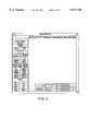
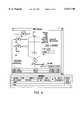
- FIG. 1is a diagram illustrating a computer system architecture for the computer implemented object oriented visualization system
- FIG. 2is a diagram illustrating an editor processor for the computer implemented object oriented visualization system
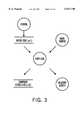
- FIG. 3is a diagram illustrating a compiler processor system for the computer implemented object oriented visualization system
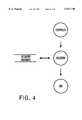
- FIG. 4is a diagram illustrating a registry processor system for the computer implemented object oriented visualization system
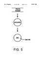
- FIG. 5is a diagram illustrating a data server processor system for the computer implemented object oriented visualization system
- FIG. 6is a diagram illustrating a run time model processor system for the computer implemented object oriented visualization system
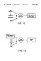
- FIG. 7Ais a diagram illustrating a general model creation system for the computer implemented object oriented visualization system
- FIG. 7Bis a diagram illustrating a detailed model creation system for the computer implemented object oriented visualization system
- FIG. 8is a diagram illustrating a top level model processor system for the computer implemented object oriented visualization system
- FIG. 9is a diagram illustrating a revised top level model processor system for the computer implemented object oriented visualization system
- FIG. 10is a diagram illustrating an absolute value dynamic script object for the computer implemented object oriented visualization system
- FIG. 11is a diagram illustrating a dynamic data sourced value dynamic script object for the computer implemented object oriented visualization system
- FIG. 12is a diagram illustrating a templating function for the computer implemented object oriented visualization system
- FIG. 13is a diagram illustrating a binding function for the computer implemented object oriented visualization system
- FIG. 14is a diagram illustrating define, template, and bind functions in the editor system for the computer implemented object oriented visualization system
- FIG. 15is a diagram illustrating a define function to assign script variables in the editor system for the computer implemented object oriented visualization system
- FIG. 16is a diagram illustrating a template function to create a smart graphical object in the editor system for the computer implemented object oriented visualization system
- FIG. 17is a diagram illustrating a bind function to assign a process tag to a smart graphical object in the editor system for the computer implemented object oriented visualization system;
- FIG. 18is a diagram illustrating a dynamic property function to assign a dynamic property to a smart graphical object in the editor system for the computer implemented object oriented visualization system;
- FIG. 19is a diagram illustrating a bind function to inter-relate properties to a smart graphical object in the editor system for the computer implemented object oriented visualization system
- FIG. 20is a diagram illustrating a template function to assign a dynamic property to a smart graphical object in the editor system for the computer implemented object oriented visualization system;
- FIG. 21is a diagram illustrating a rename variable function for a smart graphical object in the editor system for the computer implemented object oriented visualization system
- FIG. 22is a diagram illustrating a navigator function in the Run-Time environment for the computer implemented object oriented visualization system
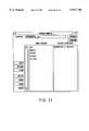
- FIG. 23is a diagram illustrating a model directory function in the Run-Time Environment for the computer implemented object oriented visualization system
- FIG. 24is a diagram illustrating a message history function in the Run-Time environment for the computer implemented object oriented visualization system
- FIG. 25is a diagram illustrating a completed model using SGOs in the Run-Time environment of the computer implemented object oriented visualization system
- FIG. 26is a diagram illustrating the navigator functions of the Run-Time environment of the computer implemented object oriented visualization system.
- FIG. 27is a diagram illustrating a demo reactor SGO in a model within the Run-Time environment of the computer implemented object oriented visualization system.
- the computer implemented object oriented systemis an object-oriented visualization environment ideally suited for use with supervisory control, process control simulation and training systems.
- the computer implemented object oriented systemenables the user to quickly create powerful, dynamic graphics capable of displaying real-time and historical information in a comprehensive picture.
- other user-defined informationcan be accessed from any source within the enterprise thanks to the use of a standard client/server architecture.
- Powerful graphics editorrich in features including 64 user-definable colors, 8 blinking colors, object grouping, animation, standard geometric shapes, and scaleable fonts.
- Import capabilityallows the incorporation of external drawings, geographical information (GIS), and AUTOCAD diagrams into graphic models.
- Object-oriented architecturespeeds up the creation and simplifies the maintenance of all graphic models.
- System-wide graphic registryensures automatic updating and distribution of graphic models to any operator workstation.
- Smart graphical objectsprovide easy data sourcing definition, along with simplified re-use.
- the computer implemented object oriented systemprovides beneficial access to enterprise-wide information through an easy to use, extensible visualization environment. This is accomplished through the integration of an advanced, object-oriented graphics system with an industry standard client/server architecture.
- a graphic modelcan consist of static and dynamic objects, animation of real-time variables, input controls (GISMOs-discussed below), and control actions.
- Static objectscan consist of elements as simple as squares, or as sophisticated as AUTOCAD drawings or bitmaps.
- Input controls within a graphic modelcan be anything from numeric or text boxes, to buttons, sliders and menus.
- SGOSmart Graphical Objects
- the computer implemented object oriented systemincludes a system-wide graphics management system known as the Graphic Model Registry. This registry manages the propagation of all models across all display platforms, guaranteeing that the most current graphic model is available for display whenever requested. It also provides validation of a graphic model during the registration phase, helping to locate data sourcing errors prior to distribution.
- VRTcomputer implemented object oriented system run-time
- the VRTis a complete display environment with a convenient navigator window for environment control. Through this starting point, the user can launch any graphic from the directory of available graphic models, or re-create entire screen environments using frame sets.
- the VRTsupports multiple windows, with each window an independent client providing pop-ups, controls, window operations (e.g. Pan and Zoom), and printing.
- securityis also provided within the VRT, so that an unauthorized user may not activate sensitive controls.
- the computer implemented object oriented systemis a complete data visualization environment, providing not just one or two pieces of the picture, but providing ease-of-use from beginning to end--from data access through the presentation of the data at the user's personal computer or workstation.
- the computer implemented object oriented system graphics systempermits the user to create and run displays showing real time process data. This section introduces the major design concepts behind the computer implemented object oriented system graphics system.
- the computer implemented object oriented system graphicsare based on, for example, the standard SL-GMS graphic library, a multi-platform toolkit for creation of dynamic graphic displays.
- SL-GMSis manufactured and distributed by SL Corporation.
- client server technologyfrom the standard Open Systems Foundation, the computer implemented object oriented system graphics display processes data from a variety of sources.
- the major component of the computer implemented object oriented systemare as follows:
- SL-GMSAny standard Graphic Modeling System, for example, the modeling system SL-GMS from SL Corporation. This software provides the underlying mechanism for editing and displaying dynamic graphics in the computer implemented object oriented system Graphics system.
- VEDComputer Implemented Object Oriented System Editor
- VMCComputer Implemented Object Oriented System Model Compiler
- VRTComputer Implemented Object Oriented System Run Time
- DCEDistributed Computing Environment
- UCXDEC TCP/IP Services
- TCP/IPTransport Control Protocol/Internet Protocol
- DECDigital Platforms
- UCXruns concurrently with DECnet. Use of UCX is optional and not a necessary ingredient of the computer implemented object oriented system.
- DataserversA standard DCE-based server (or other standard data server) that supplies process data to the computer implemented object oriented system.
- a standard dataserver toolkitis available for creating custom dataservers that access data from other sources.
- the Registrymaintains a directory of graphic models for display by the VRT. It also performs copying and synchronization of models for all nodes running VRT.
- the Registryuses DCE technology for client server operation across the network.
- the service managermaintains a directory of DCE based servers associated with the computer implemented object oriented system such as the dataservers and the Registry.
- Client applicationssuch as the VRT and the compiler use the Service Manager to locate network based servers.
- the computer implemented object oriented system graphicsuse client server technology to distribute applications across a communications network.
- Serverssuch as the Registry and dataserver provide data of various types to client applications such as the VRT.
- Clients and serversmay run on the same node or on separate nodes.
- the client server architectureis base upon the Remote Procedure Calls portion of the Distributed Computing Environment.
- Remote Procedure Callsor RPCs, allow processes to execute on other nodes in the network by handling the communication and data translation functions between the client and server.
- Each computer implemented object oriented system Graphics Systemutilizes three servers and one or more clients.
- the serversinclude:
- Dataserver--Providesprocess data for each model displayed to the operator.
- Service Manager--Provides a directory of services to client applications. Typically this includes the Registry and dataservers described above.
- FIG. 1shows the computer implemented object oriented system architecture.
- the computer implemented object oriented systemrun time client software and the display software work together to provide operator displays.
- the computer implemented object oriented system Graphics Editoris used to create dynamic graphical displays.
- the main editing windowis shown in FIG. 2 and editor functions are discussed in detail in a later section.
- the computer implemented object oriented system editoris a modified version of the SL-GMS Draw2x editor supplied by SL Corp.
- the computer implemented object oriented system model compilerillustrated in FIG. 3, validates the data source references found in a model.
- the output of the compileris an optimized model file that can be quickly loaded by the VRT Runtime software for optimum display callup times.
- Model files created by the computer implemented object oriented system editorare read by the computer implemented object oriented system model compiler.
- the compilervalidates references to the dataserver and creates a new model file optimized for display by the operator.
- the compilerenters the model in the Registry which makes it available for operator display.
- the computer implemented object oriented system model registryillustrated in FIG. 4, maintains a system wide database of compiled models.
- the registryalso provides automatic updating of all registry nodes in the system so that models are automatically copied across the network and updated when old versions of the model change.
- the compilerAfter successfully compiling a model, the compiler registers the model information in the Registry database.
- the registrymakes this information available to the VRT for operator display.
- Each node in the system used to display computer implemented object oriented system graphicshas its own Registry server.
- the computer implemented object oriented system dataserverillustrated in FIG. 5, provides process data needed for displaying dynamic graphic displays.
- Several types of dataserversare available depending on individual applications.
- Every computer implemented object oriented systemrequires at least one dataserver to transfer data between the process and dynamic graphic displays.
- the computer implemented object oriented system runtime display modulealso known as VRT and illustrated in FIG. 6, is the software that displays dynamic models to the operator.
- Step S1The graphics designer creates a graphical model using the computer implemented object oriented system Editor.
- Step S2The designer assigns dynamic behavior to objects contained in the model and links the objects to the process database.
- Step S3.The designer registers the model with the computer implemented object oriented system graphics system. This process validates process database references and updates directory information on each node in the system.
- Step S4The operator selects a model for display.
- Step S5.The system links the model to the process database and displays the dynamic model to the operator.
- FIG. 7Bis a detailed flow chart illustrating the processes of the computer implemented object oriented system.
- the computer implemented object oriented systemprompts the user to draw a graphical object (GO) in Step S10.
- the GOis provided by the user without specifying the accompanying dynamics associated therewith.
- the systemprompts the user to provide the dynamic behaviors or properties (for example, a scripting language driven by variables and values) associated with the GO in Step S11.
- the systemthen templates the GO in Step S12.
- the templating processessentially assigns token, attributes and update properties that drive the dynamic properties associated with the GO.
- the systemthen saves the templated model as a Smart Graphical Object (SGO) in Step S13.
- the systemthen loads or assigns a pointer to the SGO in Step S14.
- the assignment of a pointer to the SGOpermits the SGO to be copied multiple times by addressing the SGO via the pointer.
- the systemmay then optionally copy the SGO using the pointer in Step S15.
- the SGOis then bound to the appropriate data source by defining an appropriate tag and associating it with the token in Step S16. By filling in or assigning the data source to the token variable, a generic method of associating the data source to the token results.
- the SGO modelis then registered and stored in memory and compiled in Step S17. When the SGO is compiled successfully, the SGO model is validated, optimized with respect to structure and format, and stripped of any unnecessary processing steps. Only the dynamic properties of the SGO model are generally compiled to obtain the dynamic properties to prepare the SGO for execution, since the static properties of the SGO, i.e., the GO properties, remain generally unchanged during model execution.
- the modelis then executed or run in Step S18.
- a computer implemented object oriented system modelis a collection of objects which graphically represent real time process data.
- the computer implemented object oriented system modelsconsist of:
- GISMOS--Graphical Interactive Screen Management Objectsthat respond to user input events such as a mouse click or a key press.
- Models created with the computer implemented object oriented system Editorare stored as M1 files.
- the M1 fileis a binary file that is hardware and operating system specific.
- the librariesprovide the starting point for creating custom process graphics. To use a library object, the designer selects the object from a palette and drags it with the mouse to the main editing window.
- the objectis associated with one or more tags from the process database so that its pre-defined behavior can be activated at run time.
- Library objectscan be used as is, or modified to suit individual needs. Using the scripting language and tools found in the computer implemented object oriented system Editor, the graphics designer can create many variations of the original objects.
- the VRT processlinks the dynamic objects found in the model to the process database using one or more dataservers.
- data requests to the dataserverare specified using a tag and attribute where tag represents a point in the process database and attribute represents a field associated with the point type. For example, if tag represents the EPN F1C01 and attribute represents the input value AI -- INVL, the resulting data source specification is F1C01.AI -- INVL. Variations on this syntax exist depending on the server implementation.
- a submodelis a model used in another model. Submodels are classified as either local or external depending on how the submodel is referenced by the parent model. Any model can be a submodel. Submodels are also known as model instances. Model instances retain the dynamic properties of the original model but may be duplicated, scaled and placed anywhere in a new model. To differentiate a model instance from the original, the variables defined by the object's dynamic properties must be renamed to provide unique dynamic behavior.
- FIG. 8shows two top level models that contain local and external instances of a faceplate submodel. Both models have the identical appearance.
- modelsIn the computer implemented object oriented system graphics system, models must be compiled and registered before they can be displayed to the operator. This compilation process converts external submodels to local submodels and allows the top level model and all its submodels to be stored as a single file. As a result, changes to external submodels do not appear in the top level model unless they are recompiled.
- GISMOSor Graphical Interactive Screen Management Objects, produce an action based on an input event such as a mouse click or keyboard event.
- GISMOShave all the attributes of a typical GMS object with the additional ability to produce actions based on user input.
- a number of GISMOShave been provided in the computer implemented object oriented system library and many others are available in the standard GMS library.
- P3 buttonshave a 3 dimensional look and may be labeled with a text label to indicate their function.
- AB boxes, or Action Boxesare rectangular objects that may be placed in a model and hidden from the operator until needed. These boxes remain transparent until the diamond button in the VRT frame display is pressed indicating the position of all AB boxes. Action Boxes may be placed over other objects without changing their appearance.
- M0 Buttonsare rectangular buttons that may be placed around other objects. When the user clicks on the button, the object appears to move in and out like a standard push-button.
- TXT GISMOSare objects that accept text input. The user must click on the object to select it before entering text. Text entry must be followed by the return key.
- the input behavior associated with a GISMOis specified using a DynProp applied at t he top level of the GISMO model. When the user clicks on the GISMO, one or more callback functions are executed to obtain the desired behavior. These callbacks execute code located, for example, in the GMS library.
- Objects which exhibit dynamic behavior in response to a change in the processdo so according to a dynamic script or DynProp. Users have the option of creating their own objects and DynProps or using existing library objects to create process graphics. Library objects can also be modified to suit individual applications.
- the GMS scripting languagespecifies the dynamic properties, or DynProps, of each object in a model.
- DynPropsprovide control over many object attributes such as edge color, fill color, XY position, rotation, etc. Variables referenced by DynProps are knows as GMS variables.
- DynPropsare created using the computer implemented object oriented system editor functions Edit Dyn or Enter Dyn which are available in the Dyn Menu.
- a Dynpropconsists of an action and an action expression. For instance, the following DynProps sets the fill color of an object:
- Color value 1refers to the color number in editor color palette.
- the VRT softwaredetermines the value of the GMS variable "tank -- color" and updates the fill color of the target object.
- Values for GMS variablesmay be assigned one of two methods:
- the "Rename Vars" function in the computer implemented object oriented system editorcan be used to permanently assign a value to a GMS variable. Once defined in this manner, the object behavior will not change at run time.
- the Rename Vars functionis only available for variables used by a submodel.
- the Define or Template/Bind functionsassociate a GMS variable with a process variable so that objects change appearance in response to changes in the process.
- the following examplesillustrate these concepts.
- the designeruses the computer implemented object oriented system editor, the designer creates a model containing one submodel.
- the submodelas illustrated in FIG. 10, contains one object with the following DynProp:
- the GMS variable "a”is linked to the process database tag "epn101" and attribute "status”.
- the object's dynamic scriptupdates the fill color of the object based on the value of the process variable.
- the Dataserversupplies process values to the model when displayed to the operator by the VRT process.
- the first methoduses the Define function to directly link a script variable to a point in the process database. This method is suitable for linking simple objects to the database. Each script variable is assigned a process tag and attribute along with a server name and update rate.
- the second method of linking dynamic properties to the process databaseuses the Template and Bind functions to create a Smart Graphical Object, or SGO.
- SGOsare useful for creating complex objects that reference multiple fields of one or more tags in the process database. They are described in detail in the following section.
- a Smart Graphical Objectis a dynamic object whose variables have been linked to the process database independently of the process database tag. This provides a method of grouping variables that share one or more tags. Once an SGO has been created, only the tag(s) and servers need be specified for the system to automatically link GMS variables to the process.
- Process datais referenced from a computer implemented object oriented system graphic using a tag and attribute where tag represents a point in the process database and attribute represents a field for the given point. For example, if tag represents the EPN FIC01 and attribute represents the input value field AI -- INVL, the two specifications are appended to produce the final specification FIC01.AI -- INVL.
- the perioddelineates the tag and attribute fields to the server and is inserted automatically during model compilation. (The period used to separate tag and attribute to the server is server dependent.)
- Tag and attribute fieldsmay be further subdivided depending on the type of information requested.
- the Smart Graphical Objectprovides a method of linking the tag and attribute specification from the dataserver to a graphical object in a process known as Templating and Binding.
- Step 1Object creation. The designer creates a graphical object and writes a DynProp to define dynamic behavior. This step was discussed previously.
- Step 2Templating.
- the designerassociates the GMS variables used in the DynProp with tag attributes from the process database and assigns an update rate. Since the actual tag is unknown at the time an SGO is created, a token or placeholder is specified instead. Token will be assigned to process tags during the bind step. After completion of the Template function, the object is referred to as an SGO. SGOs can be placed in the library for general purpose use by other models.
- Step 3Binding.
- the tokens specified during the Template stepare associated with tags from the process database and a server. This allows the system to associate each GMS variable with both a tag and attribute in the process database.
- the SGOis referred to as a Bound SGO.
- the ability to assign attributes independently of the tagpromotes the creation and reuse of complex objects and is a key feature of the computer implemented object oriented system graphics system.
- the computer implemented object oriented system editorcreates model files and registers them for display to the operator.
- the computer implemented object oriented system editoris a modified version of the Draw2x editor from SL Corporation. This modified editor provides the same functionality found in Draw2x along with the following additional features:
- GMS script variablesare assigned to a valid tag and attribute in the process database.
- script variablesare associated using a two step process which assigns the tag and attribute information independently.
- the second methodproduces an object known as a Smart Graphical Object, or SGO.
- the Define functionallows the developer to assign GMS script variables to a tag and attribute in the process database.
- To invoke the Define functionselect one or more objects containing a DynProp and click on the Define button in the Object Create Control Panel. This action invokes the Define dialog sequentially for each object on the select list. If the dialog does not appear, make sure one or more objects are selected and that they contain scripts with unassigned GMS variables.
- the Define dialogcontains the information needed to assign a GMS variable to a tag in the process database.
- GMS variablesare shown in the list on the right side of the dialog. By clicking on a variable in the list, the assignments for that variable are shown on the left side of the dialog box.
- a simple rectangle objectwas created and assigned the following dynamic script.
- This scriptassigns the fill color of the rectangle to the GMS variable tank -- color.
- the GMS variable tank -- colorappears in the list of GMS variables. After clicking on the variable tank -- color, the following assignments are displayed in the dialog box:
- Tag--Server dependent fieldwhich determines the data to be fetched for the selected GMS variable. Refer to the standard server documentation to determine the correct syntax for the tag field.
- Attributes--Server dependent fieldwhich assigns an attribute for the given tag. Refer to the server documentation to determine the correct syntax for the attribute field.
- Done--Signalsthat editing is complete for the current object or SGO. Click on the Done button to either view the next object on the select list or to close the Defined SGO Object window if there are no remaining items on the select list.
- the Done buttoncan be activated by pressing the right mouse button or using the keyboard accelerator key " ⁇ CTRL>D".
- GMS Variables--Alist of all the unassigned GMS variables used in the DynProp to characterize the object or SGO. Click on the variable name to be defined. The selected variable's background color will become white. The up and down cursor keys scrolls the display to the next variable in the list.
- the Template functioncreates a Smart Graphical object, or SGO.
- SGOSmart Graphical object
- the Template SGO dialogcontains the information needed to assign a GMS variable to an attribute in the process database. It is the first step in a two step process that assigns a data source to a GMS variable. Unlike the Define function, the process database tag is not specified at this time. Instead, a token is assigned in place of the tag. During the Bind step, the token will be assigned to the actual process tag.
- GMS variablesare shown in the list on the right side of the dialog. By clicking on a variable in the list, the assignments for that variable are shown on the left side of the dialog box.
- an objectwas created and assigned a dynamic script. Part of that script is shown below: ##EQU1## This script assigns the fill color of the object to one of two values based on the value of the GMS variable dev -- stat.
- the GMS variable dev -- statappears in the list of GMS variables. After clicking on the variable dev -- stat, the variable is highlighted and the following assignments are displayed in the dialog box.
- Token--AAn arbitrary string used as a place holder for the process tag.
- the same tokenmay be assigned to multiple GMS variables or multiple tokens may be assigned for attributes that represent different process tags. Do not use the same name for the token as the actual process tag, attribute name or GMS variable name.
- Attributes--Server dependent fieldwhich assigns an attribute for a process tag. (The tag will be assigned during the Bind step.) Refer to the server documentation to determine the correct syntax for the attribute field.
- An update count of 0displays the variable information when the model is first displayed but does not refresh it.
- An update count of 0is normally used for static strings or other attributes that do not change. To minimize server loading, do not fetch data more often than necessary.
- Done--Signalsthat editing is complete for the current object. Click on the Done button to either view the next object on the select list or to choose the Define SGO Object window if there are no remaining items on the select list.
- the Done buttoncan be activated by pressing the right mouse button or by typing " ⁇ CTRL>d".
- GMS Variables--Alist of all the GMS variables used in the DynProp to characterize the object. Click on the variable name to be templated. The selected variable's background color will become white. The up and down cursor keys scrolls the display to the next GMS variable in the list.
- the Bind functionassigns a process tag to a Smart Graphical Object, or SGO.
- the GMS variables used by an objectwere assigned to attributes in the process database and one or more tokens were assigned to serve as place holders for process tags.
- the Bind functionassigns the SGO tokens created during this step to tags in the process database.
- Bindingis typically performed when creating a top level model. Every SGO needs to be bound to the process database before the model can be registered. When using SGO's from a palette or the object library, binding is the only step necessary to enable dynamic object behavior.
- To invoke the Bind SGO dialogselect one or more SGO objects and click on the Bind button in the Object Create Control Panel. If the dialog does not appear, either no objects are selected or the selected object is not an SGO object.
- Tokens assigned to the process attributes during the Template stepappear in the list on the right side of the dialog and the tag assigned to the selected token is shown in the fields on the left side of the dialog window.
- Type in the new value and press the ⁇ return>keyto complete the text entry process.
- press the Accept buttonto save the changes.
- To close the dialogpress the Done button.
- the fields contained in this dialogare described below and illustrated in FIG. 17.
- Tag--This fieldshows the process tag assigned to the highlighted token displayed in the Token List.
- Server Name--Enterthe server name providing information for the designated tag.
- Done--Signalsthat editing is complete for the current object. Click on the Done button to either view the next object on the select list or to close the BIND SGO window if there are no remaining items on the select list.
- the Done buttoncan be simulated by pressing the right mouse button or by typing " ⁇ CTRL>d".
- Token List--Alist of tokens for this object created during the Template step. Click on a token to see the current tag and server assignments. Use the up/down arrow keys to change the selected token.
- the computer implemented object oriented system model compilerprocesses files created by the computer implemented object oriented system editor to prepare them for display to the operator.
- the computer implemented object oriented system model compiler, or VMCmay be accessed from the system command prompt or from the computer implemented object oriented system Editor using the Register Model Function.
- model>is the name of the M1 file as saved by the computer implemented object oriented system Editor. If the compiler is not run from the VED -- MODEL directory, not all submodels may be found during the compilation.
- the parameter following this argumentis to be a unique string to be displayed in the computer implemented object oriented system run time directory window.
- the model namecan be enclosed in double quotes to include spaces.
- the compilerwill accept an M2 file and save it as a standard G file in SL-GMS.
- SL-GMSdoes not guarantee that all data from the M2 file will be saved in the G file.
- VMCwill print warning messages if this occurs.
- This parameterwill be displayed in the computer implemented object oriented system Run Time directory window when the model name is selected.
- the descriptioncan be enclosed in double quotes to include spaces.
- the compilerwill not register a model if there are any errors resulting from unbound Tokens, or invalid points. Using the -w switch will force the compiler to ignore those errors, and register the model. This switch does not ignore fatal errors that might occur during the validation process (for example, unable to connect to the Registry).
- the Group descriptionallows arrangement of models based on a more general subject.
- the intentis to allow the user to put in a group description and the VRT directory will allow filtering based on group name.
- the compiler outputcan be redirected with this switch. Some information (such as summary info, Registry results, or errors) will continue to be printed to the screen and to the output file.
- Using the -o switch without a filenamewill generate an output file based on the model name. For example, if the command line is:
- the output filewill be test1.out.
- the output filewill be filex.out.
- the SL-GMS graphics environmentallows additional directories to be searched to retrieve models, submodels, and GISMOS.
- the computer implemented object oriented system model compilerautomatically searches the standard GMS directories for models, and in addition, searches the directory VED -- MODEL.
- the -i switchallows additional directories to be searched before the computer implemented object oriented system specific directories. All directory paths must reside on the same physical device.
- the compilerhas various levels of output based on debug levels. As this number increases so does the amount of informational and diagnostic messages describing the internal operations of the compiler. Substitute the desired debug level for the # sign. For example, to specify debug level 2, use the command -l2. (There is generally no space between the letter "l" and the 2.)
- a predetermined filee.g., VED -- MODEL:VMC -- ARGFILE.DAT
- This switchallows the user to generate a single G file that contains all the information for the model that was to be registered. This is useful primarily to transfer the model to another system, or to have a text file for archival or reporting purposes.
- the fileis written to a predetermined directory (e.g., VMR -- G).
- the compilerIf the Verbose switch is turned on, the compiler outputs additional reporting information during the compilation process. Any output generated can be redirected to an output file with the -o switch.
- a precompiled modelis a model built against a database that differs from the current system. This function is often used for popup models.
- objectssuch as faceplates can be validated and registered without knowing specific tags in the process database.
- the following commandcompiles a model named reactor. It assigns a model name of Reactor -- A with a description of "Reactor A Cooling Vat”. The model will be registered upon completion even if warnings are generated. Once registered, the model will be available for operator display:
- VEDComputer Implemented Object Oriented System Graphics Editor
- This tutorialis designed to give a quick walk through of all the steps necessary to create working models within a standard server environment, such as the S/3 environment available via GSE Systems, Inc., in Columbia, Md.
- the low level pieces which comprise a modelare known as the FUNDAMENTAL OBJECTS. These objects basically describe what you want this object to do functionally, without any details being associated to a particular database object (EPN or point type).
- a script languageis used to detail the dynamics of the object.
- An example of a fundamental objectcould be a text box with some associated action. The following shows how to create such an object.
- Templatingis the step where the user is associating the variables defined at the fundamental level with a generic tag or label.
- all fields referencedmay be related to a particular type of field equipment; e.g., a pump using an Analog Output point.
- the token in this instancecould be "Pump -- Epn".
- the use of "Pump -- Epn" as the tokenwould relate all related attributes (database fields) to this particular pump. If more than one pump existed in the fundamental object then more than one token would be used to uniquely identify which attribute was related to which tag. So, in this instance, the tokens might be Pump -- Epn1 and Pump -- Epn2.
- Attributeis used to access the database field desired. A list of these fields can be found in Appendix A.
- VRTComputer Implemented Object Oriented System Navigator
- the first button to useis the DIR button. Select this option by clicking within the button containing the word "DIR”. Once selected another window will pop up. This is called the "Model Directory Window,” illustrated in FIG. 23, and contains a list of all successfully compiled models which are visible to the user. Models which have been compiled with the ⁇ -h ⁇ (hidden) option will not be displayed within the Directory Window.
- the usercan use the " ⁇ CTRL>D" accelerator key to invoke the Model Directory Window. An entry will exist for each model successfully completed.
- the modelhas references to database fields that have not been bound to points within the database.
- One or more components of the computer implemented object oriented systemare not currently active. Verify that the on-line server is running.
- a faulty network connectionis preventing communication with the on-line server.
- Model DirectoryOnce models exist within the Model Directory, select one by clicking on the line with that model. The selection is then highlighted. There are a number of options within the Model Directory window. The following is a summary of these options and a brief description of their functionality.
- Model Directory windowThere are a few other display only fields located within the Model Directory window. They include the following.
- Model name--Under the scrolling window which contains the list of available modelsis the name of the model which is currently selected.
- Description--Located in the Description boxis any description which was included when the currently selected model was compiled.
- the scroll barenables the user to view messages which exist beyond the current window view.
- the CLEAR HISTORY buttonwill erase the current contents of the Message Window.
- the DONE buttonwill close the Message History window and return control back to the Navigator.
- the model CIRCLESis provided as a sample of the kind of graphics which can be created with the computer implemented object oriented system graphics. This portion of the tutorial covers the model called CIRCLES, a model which demonstrates some of the interesting things which can be accomplished with the computer implemented object oriented system.
- VED -- GISMOAll finished graphics are, for example, in the directory VSN$DISK: VED.MODEL!. This is the recommended directory for top level models which will be registered and displayed from the Navigator.
- the logical VED -- MODELis defined to be this directory.
- the SGO, GISMO and non-dynamic object librariesare in the directory VED -- SGO, and copied to VED -- GISMO. Any modifications which the user wishes to make should be done in the VED -- GISMO directory.
- the palette models(but not the items on the palettes) are in the directory VED -- PALETTES. Any new palette models which are created should be put in this directory.
- the directory VED -- SUBMODSshould be used for custom or project-specific SGOs and non-dynamic objects.
- the CIRCLES demo graphicis divided into 4 areas, as illustrated in FIG. 25:
- controllocated in the bottom left hand corner of the model.
- the device areaconsists of three instances of the CIRCLE -- SGO submodel.
- CIRCLE -- SGOshows the following digital device information for ENTDCB100, ENTDCB101 and ENTDCB102 devices:
- Status colorsdisplay default device colors.
- CIRCLE -- SGOLocated under each CIRCLE -- SGO is a push button labeled with the device's EPN. When the push button is clicked upon, it will set the context to the device EPN written on the button.
- the context areapresents the tag currently stored in context.
- the context windowis an instance of VIS -- CONTEXT.
- Clear CTXthe push button labeled Clear CTX.
- Clear CTX buttonthe push button labeled Clear CTX.
- the Clear CTX buttonis clicked upon, the information displayed in CONTEXT is removed.
- the analog loop section of the modeldisplays an instance of a simplified faceplate. This faceplate displays the following information for the analog loop ENTACB100:
- VSN -- AB -- POPUP gismoLocated in the faceplate VALUE area is another VSN -- AB -- POPUP gismo. When it is clicked upon, it will pop up the FP -- CONTROL command box for ENTACB100.
- the FP -- CONTROLprovides an operator command box that supports mouse driven operator control for analog loops. To close the pop-up with the cursor inside the pop-up window, the user clicks on the right mouse button. There are two options to control the points displayed. The first option is to use the point's pop-up faceplate or command box. The second is to use the control area.
- the control areaoffers three types of control:
- the first step to issuing a commandis to set the context.
- the text entry fielddoes not clear itself once the carriage return is hit.
- the old setpoint valuemust be deleted before a new setpoint is entered.
- gismosused and the associated push button labels or location of the gismo.
- the Navigatorprovides overall management of the VRT process.
- the Navigatoris a control panel for the VRT process. It is shown in FIG. 26 and provides the following functions:
- Server Name--Name of the dataserver for the currently active contextA context specifies a tag and attribute from a given dataserver.
- Cascade & Tile--These functionsperform screen management for currently active frames.
- the Cascade buttoncauses all the computer implemented object oriented system models currently displayed to be displayed one below the other cascading down the screen. The position and size of each frame depends on configuration parameters.
- the Tile buttoncauses all the computer implemented object oriented system models currently displayed to be sized and positioned in a window pane fashion.
- Directory--Invokes the Directory windowThe directory provides a list of all registered models. If the keyboard control key is held down during this operation, the directory listing also displays models compiled with the -h (Hidden) switch.
- Save Sets--A frame setconsists of one or more frames arranged on the display and saved as a group. Frame sets are accessed using the Save Sets dialog window which is activated using the Save Sets button.
- the "Restore Set” buttonrecalls the most recently activated frame set. When a frame set is displayed, the individual frames are positioned exactly where they were originally located when the set was stored. Any frames previously opened are closed automatically.
- a frameis the working view of a dynamic Model.
- a single Navigatorsupports up to 32 Frames.
- Each framecontains a control panel that appears in the bottom portion of the frame window.
- the frame's control panelprovides the following functionality which is illustrated in FIG. 27.
- Reset--Resetzoom and pan functions and display original model. If the control key is held down while clicking on the Reset button, all popup displays associated with this frame will be closed.
- Pan--Display portions of a zoomed model that are not currently visibleWhen the pan function is active, the current view of the model can be changed by dragging the model using the mouse and primary mouse button.
- buttonsDisplay Navigation Keys--Up, down, left and right. These buttons display a new computer implemented object oriented system model in the current frame. The name of the model is displayed on the button. Associated displays are defined at model creation using the computer implemented object oriented system editor.
- Previous/Page--The Previous buttonrecalls the 8 most recent models displayed in the current frame.
- the Page buttondisplays a new model in place of the existing model.
- the page buttonis model specific and defined using the computer implemented object oriented system editor.
- Select Number--The select numberidentifies action box GISMOS which may be placed in a model.
- the numberindicates a Quick Select or Function key accelerator which may be used to activate the GISMO in place of a mouse click.
- the following tableillustrates attributes and values of one of the existing standard servers that may be associated with GOs used to create an SGO:
- each step of the present inventiontypically generates a physical electrical signal which represents a physical result of a specific step described in the flow charts.
- the flow chartsrepresent physical electrical signals which are generated and used in subsequent steps of the process. Therefore, the flowcharts represent the transforming of physical electrical signals representing physical characteristics and quantities into other physical electrical signals also representing transformed physical characteristics.
- a standard microprocessor system capable of performing the functions described for each of the above individual componentsare may also be used. Additional details relating to multiple instruction multiple data multiprocessor types of computer architectures are disclosed in greater detail in, for example, U.S. Pat. No. 5,163,131; Boxer, A., Where Buses Cannot Go, IEEE Spectrum, February 1995, pp. 41-45; and Barroso, L. A. et al., RPM: A Rapid Prototyping Engine for Multi-Processor Systems, IEEE Computer, February 1995, pp. 26-34, all of which are incorporated herein by reference.
- each of the above circuitsmay also represent computer software subroutines in a large computer program providing a computer implemented performance analysis process in accordance with the present invention.
- the computer implemented process instructing the computer to perform the model simulation and execution process described abovemay be stored on a floppy diskette tangible medium. of course, other tangible mediums may also be used such as a read only memory, a random access memory, hard disk drive or other programmable and erasable memories.
Landscapes
- Engineering & Computer Science (AREA)
- Physics & Mathematics (AREA)
- General Physics & Mathematics (AREA)
- Theoretical Computer Science (AREA)
- Computer Hardware Design (AREA)
- Evolutionary Computation (AREA)
- Geometry (AREA)
- General Engineering & Computer Science (AREA)
- Automation & Control Theory (AREA)
- Stored Programmes (AREA)
Abstract
Description
______________________________________Tag: DEV101Attribute: DEV.sub.-- STATServer: <server name>Update Rate: 1 SecondContinuous Update: Disabled______________________________________
______________________________________Token: EPN.sub.-- TAGAttribute: STATUSUpdate Rate: 1 secondContinuous Update: Disabled______________________________________
______________________________________ cur.sub.-- value = 0 fcolor ZeroColor stext cur.sub.-- value "%6.2f" < 0 fcolor NegColor stext cur.sub.-- value "%6.2f" > 0 fcolor PosColor stext cur.sub.-- value "%6.2f"______________________________________
______________________________________TOKEN: EPNATTRIBUTE: VALUEUPDATE RATE: 1 SEC______________________________________
______________________________________GISMO Button Label/Location______________________________________VSN.sub.-- P3.sub.-- SETCTX ENTDCB100VSN.sub.-- P3.sub.-- SETCTX ENTDCB101VSN.sub.-- P3.sub.-- SETCTX ENTDCB102VSN.sub.-- AB.sub.-- POPUP CIRCLE.sub.-- CONTROL pop-upVSN.sub.-- P3.sub.-- CLRCTX Clear CTXVSN.sub.-- AB.sub.-- SETCTX ENTACB100VSN.sub.-- PE.sub.-- SETVAL AutoVSN.sub.-- P3.sub.-- SETVAL ManualVSN.sub.-- P3.sub.-- SETVAL OnVSN.sub.-- P3.sub.-- SETVAL OffVSN.sub.-- PE.sub.-- CNCLDEP CancelVSN.sub.-- P3.sub.-- SNDCTX AcceptVSN AB.sub.-- POPUP FP.sub.-- CONTROL pop-up______________________________________
TABLE__________________________________________________________________________Attribute Description Legal Values__________________________________________________________________________ABSPRESS absolute pressure value Integer value returned by the RTUABSPRESSFLG absolute pressure type flag Integer value returned by the RTUABSPRESSUSE absolute pressure in use Integer value returned by the RTUADI alarm destination index Integer value in the range 0 through 255ALARMACK alarm acknowledged Integer value returned by the RTUALARMCOND alarm condition Integer value returned by the RTUALARMDBND alarm deadband Floating point value greater than 0.00000ALARMGROUP alarm group Integer value in the range 0 through 255ALARMPRIOR alarm priority Integer value returned by the RTUALGSEL conversion disable Integer value in the range 0 through 1ARGON argon value Integer value returned by the RTUARGONFLG argon value type flag Integer value returned by the RTUARGONUSE argon value in use Integer value returned by the RTUAUTOMAN auto/manual state Integer value in the range 0 through 1AVAILABLE point availability Integer value returned by the RTUBRAKET braket evaluation code Integer value returned by the RTUCDIOXDE carbon dioxide value Integer value returned by the RTUCDIOXIDEFLG carbon dioxide val type flag Integer value returned by the RTUCDIOXIDEUSE carbon dioxide val in use Integer value returned by the RTUCMONOXIDE carbon monoxide value Integer value returned by the RTUCMONOXIDEFLG carbon monoxide type flag Integer value returned by the RTUCMONOSIDEUSE carbon monoxide in use Integer value returned by the RTUCONINDEX console enable index Integer value in the range 0 through 255DECANE n-decane value Integer value returned by the RTUDECANEFLG n-decane type flag Integer value returned by the RTUDECANEUSE n-decane in use Integer value returned hy the RTUDENSDBD relative density deadband Floating point value in the range 0.000000 through 100.000000DENST relative density ref temp Integer value returned by the RTUDENSTFLG relative density ref type flag Integer value returned by the RTUDENSTUSE relative density ref in use Integer value returned by the RTUDENSV current value density Floating point value with no range restrictionsDESC descriptor string String valueDESC1 descriptor substring (not supported String value in S/3 Dataserver)DESC2 descriptor substring (not supported String value in S/3 Dataserver)DESC3 descriptor substring (not supported String value in S/3 Dataserver)DESC4 descriptor substring (not supported String value in S/3 Dataserver)DISPHI high display range Floating point value greater than DISPLODISPLO low display range Floating point value less than DISPHIEGUHI EGU range high limit Floating point value less than EGULOEGULO EGU range low limit Floating point value less than EGUHIEGUTAG EGU tag String valueERRCODE error code String value returned by the RTUETHANE ethane value Integer value returned by the RTUETHANEFLG ethane type flag Integer value returned by the RTUETHANEUSE ethane in use Integer value returned by the RTUEXCPVAL exception value Floating point value greater than 0.000000GASDBD gas comp. fraction deadband Floating point value in the range 0.000000 through 100.000000GLALARMENAB global alarm enable status Integer value in therange 0 through 1HEATDBD heating value deadband Floating point value in the range 0.000000 through 100.000000HEATSCAL heating value scaling mult. Floating point value in the range 0.000000 through 100.000000HEATVAL gross heating value Floating point value with no range restrictionsHEATVALT heating value ref. temperature Floating point value with no range restrictionsHELIUM helium value Integer value returned by the RTUHELIUMFLG helium type flag Integer value returned by the RTUHELIUMUSE helium in use Integer value returned by the RTUHEPTANE heptane value Integer value returned by the RTUHEPTANEFLG heptane type flag Integer value returned by the RTUHEPTANEUSE helium in use Integer value returned by the RTUHEXANE heptane value Integer value returned by the RTUHEXANEFLG hexane type flag Integer value returned by the RTUHEXANEUSE hexane in use Integer value returned by the RTUHIALARMLIM high alarm limit Floating point value less than HIHIALARMLIM and greater than LOALARMLIMHIALARMPRI priority of high alarm Integer value in the range 0 through 3HSULFIDE hydrogen sulfide value Integer value returned by the RTUHSULFIDEFLG hydrogen sulfide type flag Integer value returned by the RTUHSULFIDEUSE hydrogen sulfide in use Integer value returned by the RTUHTRIGCRI critical alarm trigger Integer value in the range 0 through 31HTRIGNF informational alarm trigger Integer value in the range 0 through 31HTRIGURG urgent alarm trigger Integer value in the range 0 through 31HYDROGEN hydrogen value Integer value returned by the RTUHYDROGENFLG hydrogen type flag Integer value returned by the RTUHYDROGENUSE hydrogen in use Integer value returned by the RTUIBUTANE i-butane value Integer value returned by the RTUIBUTANEFLG i-butane type flag Integer value returned by the RTUIBUTANEUSE i-butane in use Integer value returned by the RTUIPENTANE i-pentane value Integer value returned by the RTUIPENTANEFLG i-pentane type flag Integer value returned by the RTUIPENTANEUSE i-pentane in use Integer value returned by the RTULOALARMLIM low alarm limit Floating point value less than HIALARMLIM and greater than LOLOALARMLIMLOALARMPRI priority of low alarm Integer value in the range 0 through 3LOLOALARMLIM low-low alarm limit Floating point value less than LOLARMLIMLOLOALARMPRI priority of low-low limit Integer value in the range 0 through 3METHANE methane value Integer value returned by the RTUMETHANEFLG methane type flag Integer value returned by the RTUMETHANEUSE methane in use Integer value returned by the RTUMETHOD calculation method Integer value in the range 0 through 3METHOD actual calculation method Integer value returned by the RTUNAME EPN name (not supported by S/3 String value returned by the RTU Dataserver)NBUTANE n-butane value Integer value returned by the RTUNBUTANEFLG n-butane type flag Integer value returned by the RTUNBUTANEUSE n-butane in use Integer value returned by the RTUNITROGEN nitrogen value Integer value returned by the RTUNITROGENFLG nitrogen type flag Integer value returned by the RTUNITROGENUSE nitrogen in use Integer value returned by the RTUNONANE n-nonane value Integer value returned by the RTUNONANEFLG n-nonane type flag Integer value returned by the RTUNONANEUSE n-nonane in use Integer value returned by the RTUNPENTANE n-pentane value Integer value rcturned by the RTUNPENTANEFLG n-pentane type flag Integer value returned by the RTUNPENTANEUSE n-pentane in use Integer value returned by the RTUOCTANE n-octane value Integer value returned by the RTUOCTANEFLG n-octane type flag Integer value returned by the RTUOCTANEUSE n-octane in use Integer value returned by the RTUOXYGEN oxygen value Integer value returned by the RTUOXYGENFLG oxygen type flag Integer value returned by the RTUOXYGENUSE oxygen in use Integer value returned by the RTUPNUM point number Integer value returned by the RTUPRENAB periodic report enable flag Integer value returned by the RTUPRESDBD pressure deadband Floating point value in the range of 0.000000 through 100.000000PRESSCAL pressure scaline multiplier Floating point value in the range of 0.000000 through 100.000000PRESSURE pressure value Integer value returned by the RTUPRESSUREFLG pressure type flag Integer value returned by the RTUPRESSUREUSE pressure in use Integer value returned by the RTUPROPANE propane type flag Integer value returned by the RTUPROPANEUSE propane in use Integer value returned by the RTUPTYPE point type Integer value returned by the RTUQTAG quaiity tag string String valueQUELALARMPRI questionable alarm priority Integer value in the range 0 through 3RELP ref. heating val pressure Integer value returned by the RTURELPFLG ref. heat val pressure type flag Integer value returned by the RTURELPUSE ref. heat val pressure in use Integer value returned by the RTUREMLOC remote/local status Integer value in the range 0 through 1REPORT backup update report rate Integer value; legal range of 0.255 for host CALC points, 0-2550 for all othersROCALARMLIM rate of change alarm limit Floating point value greater than 0.000000ROCALARMPRI rate of change alarm priority Integer value in the range of 0 through 3RPHASE report phase Integer value in the range 0 through 255RTU RTU where point is defined Integer value returned by the RTURXENAB report-by-exception enable Integer value in the range 0 through 1SAUTOMAN auto/manual state Integer value returned by the RTUSCANENAB scan enable Integer value in the range 0 through 1SCANINT scan interval Integer value in the range 0 through 255SG specific gravity value Floating point value with no range restrictionsSPHASE scan phase Integer value in the range 0 through 255STATUS current status word Integer value returned by the RTUTEMP temperature value Integer value returned by the RTUTEMPDBD temperature deadband Floating point value in the range 0.000000 through 100.000000TEMPFLG temperature type flag Integer value returned by the RTUTEMPTYP temperature scale Integer value in the range 0 through 3TEMPUSE temperature in use Integer value returned by the RTUVALUE current value Floating point value with no range restrictionsWATER h20 value Integer value returned by the RTUWATERFLG h20 type flag Integer value returned by the RTUWATERUSE h20 in use Integer value returned by the RTUZ compressibility value Floating point value with no range restrictionsZB base compressibility value Floating point value with no range restrictions__________________________________________________________________________
Claims (22)
Priority Applications (1)
| Application Number | Priority Date | Filing Date | Title |
|---|---|---|---|
| US08/698,584US5917730A (en) | 1995-08-17 | 1996-08-16 | Computer implemented object oriented visualization system and method |
Applications Claiming Priority (2)
| Application Number | Priority Date | Filing Date | Title |
|---|---|---|---|
| US241195P | 1995-08-17 | 1995-08-17 | |
| US08/698,584US5917730A (en) | 1995-08-17 | 1996-08-16 | Computer implemented object oriented visualization system and method |
Publications (1)
| Publication Number | Publication Date |
|---|---|
| US5917730Atrue US5917730A (en) | 1999-06-29 |
Family
ID=26670343
Family Applications (1)
| Application Number | Title | Priority Date | Filing Date |
|---|---|---|---|
| US08/698,584Expired - Fee RelatedUS5917730A (en) | 1995-08-17 | 1996-08-16 | Computer implemented object oriented visualization system and method |
Country Status (1)
| Country | Link |
|---|---|
| US (1) | US5917730A (en) |
Cited By (126)
| Publication number | Priority date | Publication date | Assignee | Title |
|---|---|---|---|---|
| US6081812A (en)* | 1998-02-06 | 2000-06-27 | Ncr Corporation | Identifying at-risk components in systems with redundant components |
| EP1087276A1 (en)* | 1999-09-21 | 2001-03-28 | Va Tech Elin GmbH | Method for simulation and/or surveillance and/or control of an industrial installation |
| US6212674B1 (en)* | 1996-04-22 | 2001-04-03 | Alcatel | Graphic control process for controlling operations in a network management system |
| US6230200B1 (en)* | 1997-09-08 | 2001-05-08 | Emc Corporation | Dynamic modeling for resource allocation in a file server |
| US6247077B1 (en) | 1998-02-06 | 2001-06-12 | Ncr Corporation | Highly-scalable parallel processing computer system architecture |
| GB2358487A (en)* | 2000-01-20 | 2001-07-25 | Fisher Rosemount Systems Inc | Designing, configuring and managing a process control network |
| US6269475B1 (en)* | 1997-06-02 | 2001-07-31 | Webgain, Inc. | Interface for object oriented programming language |
| WO2001079946A1 (en)* | 2000-04-14 | 2001-10-25 | Siemens Aktiengesellschaft | Method and tool for modeling and/or simulating a technical installation |
| US6336084B1 (en)* | 1999-05-11 | 2002-01-01 | Ford Global Technologies, Inc. | Three-way catalyst model for an engine air-to-fuel ratio control system |
| US6339838B1 (en)* | 1998-01-02 | 2002-01-15 | At&T Corp. | Control of commercial processes |
| US6349290B1 (en)* | 1998-06-30 | 2002-02-19 | Citibank, N.A. | Automated system and method for customized and personalized presentation of products and services of a financial institution |
| EP1093038A3 (en)* | 1999-10-15 | 2002-05-02 | Siemens Aktiengesellschaft | System and method for processing data relevant for the process control of a technical installation |
| US20020099789A1 (en)* | 2000-12-06 | 2002-07-25 | Rudolph Eric H. | Methods and systems for processing multi-media editing projects |
| US20020099758A1 (en)* | 2000-12-06 | 2002-07-25 | Miller Daniel J. | System and related methods for reducing memory requirements of a media processing system |
| US20020099869A1 (en)* | 2000-12-06 | 2002-07-25 | Miller Daniel J. | Methods and systems for implementing dynamic properties on objects that support only static properties |
| US20020099732A1 (en)* | 2000-12-06 | 2002-07-25 | Miller Daniel J. | Interface and related methods for dynamically generating a filter graph in a development system |
| US20020099840A1 (en)* | 2000-12-06 | 2002-07-25 | Miller Daniel J. | System and related interfaces supporting the processing of media content |
| US20020097980A1 (en)* | 2000-12-06 | 2002-07-25 | Rudolph Eric H. | Methods and systems for managing multiple inputs and methods and systems for processing media content |
| US20020099860A1 (en)* | 2000-12-06 | 2002-07-25 | Miller Daniel J. | System and related methods for reducing source filter invocation in a development project |
| WO2001001206A3 (en)* | 1999-06-30 | 2002-08-08 | Strategic Simulation Systems I | System dynamics model builder and simulator |
| US20020154165A1 (en)* | 2000-12-18 | 2002-10-24 | Ricoh Co., Ltd. | Windows resource file parameterization system and method |
| US20030074483A1 (en)* | 1998-09-25 | 2003-04-17 | Apple Computer, Inc. | Method and apparatus for coordination of client/server processes |
| WO2003046671A1 (en)* | 2001-11-27 | 2003-06-05 | 3M Innovative Properties Company | Reusable software components for invoking computational models |
| US6587746B1 (en)* | 1996-12-04 | 2003-07-01 | D'souza Melanius | Process and apparatus for facilitating automatic production of drawing using a CAD system |
| US20030193525A1 (en)* | 2002-04-11 | 2003-10-16 | Nygaard Richard A. | Expedited selection of items from a list within a drop down menu of an eye diagram analyzer |
| US20040078180A1 (en)* | 2002-10-16 | 2004-04-22 | Allen Richard Craig | Method for automatically decomposing dynamic system models into submodels |
| US6753050B1 (en) | 2000-04-03 | 2004-06-22 | Jody A. Dalvey | Image transfer sheet |
| US20040122534A1 (en)* | 2002-08-30 | 2004-06-24 | Paulin Matthew A. | Method for facilitating computer-based modeling |
| US20040135803A1 (en)* | 2000-12-06 | 2004-07-15 | Miller Daniel J. | Interface and related methods for reducing source accesses in a development system |
| US6768499B2 (en) | 2000-12-06 | 2004-07-27 | Microsoft Corporation | Methods and systems for processing media content |
| US6789054B1 (en)* | 1999-04-25 | 2004-09-07 | Mahmoud A. Makhlouf | Geometric display tools and methods for the visual specification, design automation, and control of adaptive real systems |
| US20040205179A1 (en)* | 2003-03-06 | 2004-10-14 | Hunt Galen C. | Integrating design, deployment, and management phases for systems |
| US20040210623A1 (en)* | 2003-03-06 | 2004-10-21 | Aamer Hydrie | Virtual network topology generation |
| US6810522B2 (en)* | 1998-10-07 | 2004-10-26 | Invensys Systems, Inc. | Method and system for associating parameters of containers and contained objects |
| US20040216045A1 (en)* | 2001-07-26 | 2004-10-28 | Maurice Martin | System and process for gathering recording and validating requirments for computer applications |
| US20050033825A1 (en)* | 2000-12-06 | 2005-02-10 | Microsoft Corporation | Method of sharing a parcer |
| US20050048230A1 (en)* | 1999-09-09 | 2005-03-03 | Jodi A. Dalvey | Method of image transfer on a colored base |
| US20050060161A1 (en)* | 2000-12-06 | 2005-03-17 | Microsoft Corporation | Methods and systems for mixing digital audio signals |
| US20050071394A1 (en)* | 2003-09-25 | 2005-03-31 | Martyn Michael K. | System and method for displaying document metadata |
| US20050091573A1 (en)* | 2001-04-09 | 2005-04-28 | Microsoft Corporation | Animation on object user interface |
| US20050108364A1 (en)* | 2003-11-14 | 2005-05-19 | Callaghan David M. | Systems and methods that utilize scalable vector graphics to provide web-based visualization of a device |
| US20050193377A1 (en)* | 2004-01-29 | 2005-09-01 | Kenji Seto | Method and apparatus for translation of process models to facilitate usage by plural simulation applications |
| US20050257204A1 (en)* | 2004-05-17 | 2005-11-17 | Invensys Systems, Inc. | System and method for developing animated visualization interfaces |
| US20060031539A1 (en)* | 1997-03-31 | 2006-02-09 | Apple Computer, Inc. | Method and apparatus for updating and synchronizing information between a client and server |
| US20060034263A1 (en)* | 2003-03-06 | 2006-02-16 | Microsoft Corporation | Model and system state synchronization |
| US20060167667A1 (en)* | 2005-01-27 | 2006-07-27 | Rockwell Automation Technologies, Inc. | Agent simulation development environment |
| US20060176309A1 (en)* | 2004-11-15 | 2006-08-10 | Shirish Gadre | Video processor having scalar and vector components |
| US7103677B2 (en) | 2000-12-06 | 2006-09-05 | Microsoft Corporation | Methods and systems for efficiently processing compressed and uncompressed media content |
| US7114162B2 (en) | 2000-12-06 | 2006-09-26 | Microsoft Corporation | System and methods for generating and managing filter strings in a filter graph |
| US20060227130A1 (en)* | 2005-03-22 | 2006-10-12 | Vijayvardhan Elchuri | Graphical method and system for making drawings directly in three-dimensions on a computer monitor or other display device |
| US20060232927A1 (en)* | 2005-04-15 | 2006-10-19 | Microsoft Corporation | Model-based system monitoring |
| US20060235962A1 (en)* | 2005-04-15 | 2006-10-19 | Microsoft Corporation | Model-based system monitoring |
| US20060235650A1 (en)* | 2005-04-15 | 2006-10-19 | Microsoft Corporation | Model-based system monitoring |
| US20060235664A1 (en)* | 2005-04-15 | 2006-10-19 | Microsoft Corporation | Model-based capacity planning |
| US20060242172A1 (en)* | 2005-04-22 | 2006-10-26 | Igor Tsyganskiy | Systems and methods for transforming logic entities of a business application into an object-oriented model |
| US20060242174A1 (en)* | 2005-04-22 | 2006-10-26 | Igor Tsyganskiy | Systems and methods for using object-oriented tools to debug business applications |
| US20060242188A1 (en)* | 2005-04-22 | 2006-10-26 | Igor Tsyganskiy | Methods of exposing a missing collection of application elements as deprecated |
| US20060241961A1 (en)* | 2005-04-22 | 2006-10-26 | Igor Tsyganskiy | Methods of optimizing legacy application layer control structure using refactoring |
| US20060242170A1 (en)* | 2005-04-22 | 2006-10-26 | Igor Tsyganskiy | Systems and methods for off-line modeling a business application |
| US20060242194A1 (en)* | 2005-04-22 | 2006-10-26 | Igor Tsyganskiy | Systems and methods for modeling and manipulating a table-driven business application in an object-oriented environment |
| US20060242173A1 (en)* | 2005-04-22 | 2006-10-26 | Igor Tsyganskiy | Methods of using an integrated development environment to configure business applications |
| US20060242171A1 (en)* | 2005-04-22 | 2006-10-26 | Igor Tsyganskiy | Methods of using code-based case tools to verify application layer configurations |
| US20060242175A1 (en)* | 2005-04-22 | 2006-10-26 | Igor Tsyganskiy | Systems and methods for identifying problems of a business application in a customer support system |
| US20060242177A1 (en)* | 2005-04-22 | 2006-10-26 | Igor Tsyganskiy | Methods of exposing business application runtime exceptions at design time |
| US20060271845A1 (en)* | 2005-05-31 | 2006-11-30 | Butlin Stefan G | Automatic updating of variables in a data language |
| US20060282458A1 (en)* | 2005-04-22 | 2006-12-14 | Igor Tsyganskiy | Methods and systems for merging business process configurations |
| US20060293940A1 (en)* | 2005-04-22 | 2006-12-28 | Igor Tsyganskiy | Methods and systems for applying intelligent filters and identifying life cycle events for data elements during business application debugging |
| US20060293935A1 (en)* | 2005-04-22 | 2006-12-28 | Igor Tsyganskiy | Methods and systems for incrementally exposing business application errors using an integrated display |
| US20060294158A1 (en)* | 2005-04-22 | 2006-12-28 | Igor Tsyganskiy | Methods and systems for data-focused debugging and tracing capabilities |
| US20070005320A1 (en)* | 2005-06-29 | 2007-01-04 | Microsoft Corporation | Model-based configuration management |
| EP1212704A4 (en)* | 1999-07-19 | 2007-04-25 | Ibm | Spreadsheet cell-data source binding |
| US20070179645A1 (en)* | 2000-01-20 | 2007-08-02 | Fisher-Rosemount Systems, Inc | Enhanced tool for managing a process control network |
| US7287226B2 (en) | 2000-12-06 | 2007-10-23 | Microsoft Corporation | Methods and systems for effecting video transitions represented by bitmaps |
| US7295884B1 (en) | 2005-06-20 | 2007-11-13 | The United States Of America As Represented By The Administrator Of The National Aeronautics And Space Administration | System and method of designing a load bearing layer of an inflatable vessel |
| US20070277151A1 (en)* | 2006-05-17 | 2007-11-29 | The Mathworks, Inc. | Action languages for unified modeling language model |
| US20070283283A1 (en)* | 2006-06-05 | 2007-12-06 | Jun-Fu Lin | Method of Editing Default Graphic Object for Man-Machine Interface and Editor using the same |
| US20080270977A1 (en)* | 2007-04-27 | 2008-10-30 | Boomi, Inc. | System and method for automated on-demand creation of a customized software application |
| US20090102832A1 (en)* | 2007-10-17 | 2009-04-23 | Jay Behr | Selective refresh of computer-aided design drawings |
| US7542980B2 (en) | 2005-04-22 | 2009-06-02 | Sap Ag | Methods of comparing and merging business process configurations |
| US20090172633A1 (en)* | 2005-04-22 | 2009-07-02 | Sap Ag | Methods of transforming application layer structure as objects |
| US7567504B2 (en) | 2003-06-30 | 2009-07-28 | Microsoft Corporation | Network load balancing with traffic routing |
| US7574343B2 (en) | 2000-10-24 | 2009-08-11 | Microsoft Corporation | System and method for logical modeling of distributed computer systems |
| US20090219292A1 (en)* | 2008-03-03 | 2009-09-03 | Pixar | Systems and methods for specifying arbitrary animation controls for model objects |
| US7590736B2 (en) | 2003-06-30 | 2009-09-15 | Microsoft Corporation | Flexible network load balancing |
| US7606898B1 (en) | 2000-10-24 | 2009-10-20 | Microsoft Corporation | System and method for distributed management of shared computers |
| US7606929B2 (en) | 2003-06-30 | 2009-10-20 | Microsoft Corporation | Network load balancing with connection manipulation |
| US7613822B2 (en) | 2003-06-30 | 2009-11-03 | Microsoft Corporation | Network load balancing with session information |
| US7630877B2 (en) | 2003-03-06 | 2009-12-08 | Microsoft Corporation | Architecture for distributed computing system and automated design, deployment, and management of distributed applications |
| US7636917B2 (en) | 2003-06-30 | 2009-12-22 | Microsoft Corporation | Network load balancing with host status information |
| US20100031228A1 (en)* | 2008-07-30 | 2010-02-04 | Luk Lamellen Und Kupplungsbau Beteiligungs Kg | Process for testing models |
| US7669235B2 (en) | 2004-04-30 | 2010-02-23 | Microsoft Corporation | Secure domain join for computing devices |
| US7689676B2 (en) | 2003-03-06 | 2010-03-30 | Microsoft Corporation | Model-based policy application |
| US7778422B2 (en) | 2004-02-27 | 2010-08-17 | Microsoft Corporation | Security associations for devices |
| US20100262900A1 (en)* | 2009-04-13 | 2010-10-14 | Honeywell International Inc. | Utilizing spreadsheet user interfaces with flowsheets of a cpi simulation system |
| US20110067806A1 (en)* | 1998-09-10 | 2011-03-24 | Jodi A. Schwendimann | Image transfer sheet |
| US7941309B2 (en) | 2005-11-02 | 2011-05-10 | Microsoft Corporation | Modeling IT operations/policies |
| US20110111146A1 (en)* | 2004-02-10 | 2011-05-12 | Williams Scott A | Image transfer material and polymer composition |
| US8083589B1 (en) | 2005-04-15 | 2011-12-27 | Reference, LLC | Capture and utilization of real-world data for use in gaming systems such as video games |
| US20120062933A1 (en)* | 2010-09-10 | 2012-03-15 | Jun Zeng | Controlled job release in print manufacturing |
| US8280696B1 (en)* | 2008-02-20 | 2012-10-02 | Ultra Deep, LLC | Method for computer aided design of conduit |
| US8549513B2 (en) | 2005-06-29 | 2013-10-01 | Microsoft Corporation | Model-based virtual system provisioning |
| US8589207B1 (en) | 2012-05-15 | 2013-11-19 | Dell Products, Lp | System and method for determining and visually predicting at-risk integrated processes based on age and activity |
| US8621001B2 (en) | 2000-03-30 | 2013-12-31 | Ebay Inc. | System and method for dynamically changing the content of an information display |
| US20140075357A1 (en)* | 2012-09-12 | 2014-03-13 | International Business Machines Corporation | Enabling real-time opertional environment conformity to an enterprise model |
| US8676886B2 (en) | 2000-03-30 | 2014-03-18 | Ebay, Inc. | System and method for dynamically changing the content of an information display |
| US20140173472A1 (en)* | 2008-08-19 | 2014-06-19 | Rockwell Automation Technologies, Inc. | Visualization profiles and templates for auto-configuration of industrial automation systems |
| US8782103B2 (en) | 2012-04-13 | 2014-07-15 | Dell Products, Lp | Monitoring system for optimizing integrated business processes to work flow |
| US8805716B2 (en) | 2012-03-19 | 2014-08-12 | Dell Products, Lp | Dashboard system and method for identifying and monitoring process errors and throughput of integration software |
| US8943076B2 (en) | 2012-02-06 | 2015-01-27 | Dell Products, Lp | System to automate mapping of variables between business process applications and method therefor |
| US8954870B2 (en) | 2010-10-08 | 2015-02-10 | Irise | System and method for extending a visualization platform |
| US9015106B2 (en) | 2012-04-30 | 2015-04-21 | Dell Products, Lp | Cloud based master data management system and method therefor |
| US9069898B2 (en) | 2012-05-31 | 2015-06-30 | Dell Products, Lp | System for providing regression testing of an integrated process development system and method therefor |
| US9092244B2 (en) | 2012-06-07 | 2015-07-28 | Dell Products, Lp | System for developing custom data transformations for system integration application programs |
| US9158782B2 (en) | 2012-04-30 | 2015-10-13 | Dell Products, Lp | Cloud based master data management system with configuration advisor and method therefore |
| US9183074B2 (en) | 2013-06-21 | 2015-11-10 | Dell Products, Lp | Integration process management console with error resolution interface |
| US9606995B2 (en) | 2012-04-30 | 2017-03-28 | Dell Products, Lp | Cloud based master data management system with remote data store and method therefor |
| US9639353B1 (en) | 2016-09-19 | 2017-05-02 | Semmle Limited | Computing quality metrics of source code developers |
| US9710282B2 (en) | 2011-12-21 | 2017-07-18 | Dell Products, Lp | System to automate development of system integration application programs and method therefor |
| USD810104S1 (en) | 2015-11-16 | 2018-02-13 | Kohler, Co. | Display screen with graphical user interface |
| USD811423S1 (en) | 2015-11-16 | 2018-02-27 | Kohler, Co. | Display screen with graphical user interface |
| US10095678B2 (en) | 2009-04-13 | 2018-10-09 | Honeywell International Inc. | Database user interfaces with flowsheets of a simulation system |
| US10281507B2 (en) | 2014-11-21 | 2019-05-07 | Kohler Co. | Generator sizing |
| US10417597B2 (en) | 2012-09-12 | 2019-09-17 | International Business Machines Corporation | Enabling synchronicity between architectural models and operating environments |
| US10498858B2 (en) | 2016-12-14 | 2019-12-03 | Dell Products, Lp | System and method for automated on-demand creation of and execution of a customized data integration software application |
| US10810009B2 (en) | 2017-07-14 | 2020-10-20 | Microsoft Technology Licensing, Llc | Visualizations of software project and contributor activity |
| US12151496B2 (en) | 2020-01-21 | 2024-11-26 | Ready, Set, Co., LLC | Multiple layered print structure and apparatus for fabric or cloth |
Citations (10)
| Publication number | Priority date | Publication date | Assignee | Title |
|---|---|---|---|---|
| US3919720A (en)* | 1973-02-23 | 1975-11-11 | Westinghouse Electric Corp | Nuclear power plant training simulator modeling organization and method |
| US4977529A (en)* | 1973-02-23 | 1990-12-11 | Westinghouse Electric Corp. | Training simulator for a nuclear power plant |
| US5163131A (en)* | 1989-09-08 | 1992-11-10 | Auspex Systems, Inc. | Parallel i/o network file server architecture |
| US5305221A (en)* | 1990-05-04 | 1994-04-19 | Atherton Robert W | Real world modeling and control process for integrated manufacturing equipment |
| US5315530A (en)* | 1990-09-10 | 1994-05-24 | Rockwell International Corporation | Real-time control of complex fluid systems using generic fluid transfer model |
| US5418710A (en)* | 1991-10-31 | 1995-05-23 | Kabushiki Kaisha Toshiba | Simulator using a neural network |
| US5490096A (en)* | 1992-06-24 | 1996-02-06 | Kabushiki Kaisha Toshiba | Visual simulation apparatus |
| US5655067A (en)* | 1993-08-03 | 1997-08-05 | Hitachi, Ltd. | Animation generating method in a design supporting system |
| US5666297A (en)* | 1994-05-13 | 1997-09-09 | Aspen Technology, Inc. | Plant simulation and optimization software apparatus and method using dual execution models |
| US5680590A (en)* | 1990-09-21 | 1997-10-21 | Parti; Michael | Simulation system and method of using same |
- 1996
- 1996-08-16USUS08/698,584patent/US5917730A/ennot_activeExpired - Fee Related
Patent Citations (10)
| Publication number | Priority date | Publication date | Assignee | Title |
|---|---|---|---|---|
| US3919720A (en)* | 1973-02-23 | 1975-11-11 | Westinghouse Electric Corp | Nuclear power plant training simulator modeling organization and method |
| US4977529A (en)* | 1973-02-23 | 1990-12-11 | Westinghouse Electric Corp. | Training simulator for a nuclear power plant |
| US5163131A (en)* | 1989-09-08 | 1992-11-10 | Auspex Systems, Inc. | Parallel i/o network file server architecture |
| US5305221A (en)* | 1990-05-04 | 1994-04-19 | Atherton Robert W | Real world modeling and control process for integrated manufacturing equipment |
| US5315530A (en)* | 1990-09-10 | 1994-05-24 | Rockwell International Corporation | Real-time control of complex fluid systems using generic fluid transfer model |
| US5680590A (en)* | 1990-09-21 | 1997-10-21 | Parti; Michael | Simulation system and method of using same |
| US5418710A (en)* | 1991-10-31 | 1995-05-23 | Kabushiki Kaisha Toshiba | Simulator using a neural network |
| US5490096A (en)* | 1992-06-24 | 1996-02-06 | Kabushiki Kaisha Toshiba | Visual simulation apparatus |
| US5655067A (en)* | 1993-08-03 | 1997-08-05 | Hitachi, Ltd. | Animation generating method in a design supporting system |
| US5666297A (en)* | 1994-05-13 | 1997-09-09 | Aspen Technology, Inc. | Plant simulation and optimization software apparatus and method using dual execution models |
Non-Patent Citations (4)
| Title |
|---|
| A. Boxer, "Where Buses Cannot Go", IEEE Spectrum, Feb. 1995, pp. 41-45. |
| A. Boxer, Where Buses Cannot Go , IEEE Spectrum, Feb. 1995, pp. 41 45.* |
| L.A. Barroso et al., "RPM: A Rapid Prototyping Engine for Multiprocessor Systems", IEEE Computer, Feb. 1995, pp. 26-34. |
| L.A. Barroso et al., RPM: A Rapid Prototyping Engine for Multiprocessor Systems , IEEE Computer, Feb. 1995, pp. 26 34.* |
Cited By (291)
| Publication number | Priority date | Publication date | Assignee | Title |
|---|---|---|---|---|
| US6212674B1 (en)* | 1996-04-22 | 2001-04-03 | Alcatel | Graphic control process for controlling operations in a network management system |
| US6587746B1 (en)* | 1996-12-04 | 2003-07-01 | D'souza Melanius | Process and apparatus for facilitating automatic production of drawing using a CAD system |
| US7529841B2 (en)* | 1997-03-31 | 2009-05-05 | Apple Inc. | Method and apparatus for updating and synchronizing information between a client and server |
| US20060031539A1 (en)* | 1997-03-31 | 2006-02-09 | Apple Computer, Inc. | Method and apparatus for updating and synchronizing information between a client and server |
| US6269475B1 (en)* | 1997-06-02 | 2001-07-31 | Webgain, Inc. | Interface for object oriented programming language |
| US6230200B1 (en)* | 1997-09-08 | 2001-05-08 | Emc Corporation | Dynamic modeling for resource allocation in a file server |
| US6339838B1 (en)* | 1998-01-02 | 2002-01-15 | At&T Corp. | Control of commercial processes |
| US6081812A (en)* | 1998-02-06 | 2000-06-27 | Ncr Corporation | Identifying at-risk components in systems with redundant components |
| US6247077B1 (en) | 1998-02-06 | 2001-06-12 | Ncr Corporation | Highly-scalable parallel processing computer system architecture |
| US6349290B1 (en)* | 1998-06-30 | 2002-02-19 | Citibank, N.A. | Automated system and method for customized and personalized presentation of products and services of a financial institution |
| US8826902B2 (en) | 1998-09-10 | 2014-09-09 | Jodi A. Schwendimann | Image transfer sheet |
| US8197918B2 (en) | 1998-09-10 | 2012-06-12 | Jodi A. Schwendimann | Image transfer sheet |
| US8541071B2 (en) | 1998-09-10 | 2013-09-24 | Jodi A. Schwendimann | Image transfer sheet |
| USRE42541E1 (en) | 1998-09-10 | 2011-07-12 | Jodi A. Schwendimann | Image transfer sheet |
| US20110067806A1 (en)* | 1998-09-10 | 2011-03-24 | Jodi A. Schwendimann | Image transfer sheet |
| US20030074483A1 (en)* | 1998-09-25 | 2003-04-17 | Apple Computer, Inc. | Method and apparatus for coordination of client/server processes |
| US7233972B2 (en)* | 1998-09-25 | 2007-06-19 | Apple Inc. | Method and apparatus for coordination of client/server processes |
| US20070250565A1 (en)* | 1998-09-25 | 2007-10-25 | Minow Martin A | Method and apparatus for coordination of client/server processes |
| US20100115531A1 (en)* | 1998-10-07 | 2010-05-06 | Jay Cook | Method and system for associating parameters of containers and contained objects |
| US6810522B2 (en)* | 1998-10-07 | 2004-10-26 | Invensys Systems, Inc. | Method and system for associating parameters of containers and contained objects |
| US8020173B2 (en) | 1998-10-07 | 2011-09-13 | Invensys Systems, Inc. | Method and system for associating parameters of containers and contained objects |
| US6789054B1 (en)* | 1999-04-25 | 2004-09-07 | Mahmoud A. Makhlouf | Geometric display tools and methods for the visual specification, design automation, and control of adaptive real systems |
| US6336084B1 (en)* | 1999-05-11 | 2002-01-01 | Ford Global Technologies, Inc. | Three-way catalyst model for an engine air-to-fuel ratio control system |
| WO2001001206A3 (en)* | 1999-06-30 | 2002-08-08 | Strategic Simulation Systems I | System dynamics model builder and simulator |
| EP1212704A4 (en)* | 1999-07-19 | 2007-04-25 | Ibm | Spreadsheet cell-data source binding |
| US20080305288A1 (en)* | 1999-09-09 | 2008-12-11 | Dalvey Jodi A | Method of image transfer on a colored base |
| US8703256B2 (en) | 1999-09-09 | 2014-04-22 | Jodi A. Schwendimann | Image transfer on a colored base |
| US9776389B2 (en) | 1999-09-09 | 2017-10-03 | Jodi A. Schwendimann | Image transfer on a colored base |
| US8361574B2 (en) | 1999-09-09 | 2013-01-29 | Jodi A. Schwendimann | Image transfer on a colored base |
| US20080149263A1 (en)* | 1999-09-09 | 2008-06-26 | Schwendimann, Jodi A. | Method of image transfer on a colored base |
| US7754042B2 (en) | 1999-09-09 | 2010-07-13 | Jodi A. Schwendimann | Method of image transfer on a colored base |
| US20050048230A1 (en)* | 1999-09-09 | 2005-03-03 | Jodi A. Dalvey | Method of image transfer on a colored base |
| US20080305253A1 (en)* | 1999-09-09 | 2008-12-11 | Dalvey Jodi A | Method of image transfer on a colored base |
| US7749581B2 (en) | 1999-09-09 | 2010-07-06 | Jodi A. Schwendimann | Image transfer on a colored base |
| US7766475B2 (en) | 1999-09-09 | 2010-08-03 | Jodi A. Schwendimann | Image transfer on a colored base |
| US9321298B2 (en) | 1999-09-09 | 2016-04-26 | Jodi A. Schwendimann | Image transfer on a colored base |
| US7771554B2 (en) | 1999-09-09 | 2010-08-10 | Jodi A. Schwendimann | Image transfer on a colored base |
| USRE41623E1 (en) | 1999-09-09 | 2010-09-07 | Jodi A. Schwendimann | Method of image transfer on a colored base |
| US20080302473A1 (en)* | 1999-09-09 | 2008-12-11 | Dalvey Jodi A | Method of image transfer on a colored base |
| US20100323132A1 (en)* | 1999-09-09 | 2010-12-23 | Schwendimann, Jodi A. | Image transfer on a colored base |
| US7824748B2 (en) | 1999-09-09 | 2010-11-02 | Jodi A. Schwendimann | Image transfer on a colored base |
| EP1087276A1 (en)* | 1999-09-21 | 2001-03-28 | Va Tech Elin GmbH | Method for simulation and/or surveillance and/or control of an industrial installation |
| WO2001022182A1 (en)* | 1999-09-21 | 2001-03-29 | Va Tech Elin Gmbh | Method for simulating and/or monitoring and/or controlling an industrial installation |
| EP1093038A3 (en)* | 1999-10-15 | 2002-05-02 | Siemens Aktiengesellschaft | System and method for processing data relevant for the process control of a technical installation |
| US6772017B1 (en) | 2000-01-20 | 2004-08-03 | Fisher-Rosemount Systems, Inc. | Tool for configuring and managing a process control network including the use of spatial information |
| US7474929B2 (en) | 2000-01-20 | 2009-01-06 | Fisher-Rosemount Systems, Inc. | Enhanced tool for managing a process control network |
| US7010362B2 (en)* | 2000-01-20 | 2006-03-07 | Fisher-Rosemount Systems, Inc. | Tool for configuring and managing a process control network including the use of spatial information |
| GB2358487B (en)* | 2000-01-20 | 2004-07-28 | Fisher Rosemount Systems Inc | Method and apparatus for designing and managing the representation of a process control network. |
| GB2358487A (en)* | 2000-01-20 | 2001-07-25 | Fisher Rosemount Systems Inc | Designing, configuring and managing a process control network |
| US20070179645A1 (en)* | 2000-01-20 | 2007-08-02 | Fisher-Rosemount Systems, Inc | Enhanced tool for managing a process control network |
| US20050010307A1 (en)* | 2000-01-20 | 2005-01-13 | Fisher-Rosemount Systems,Inc. | Tool for configuring and managing a process control network including the use of spatial information |
| US20080312757A9 (en)* | 2000-01-20 | 2008-12-18 | Fisher-Rosemount Systems, Inc | Enhanced tool for managing a process control network |
| US9576315B2 (en) | 2000-03-30 | 2017-02-21 | Paypal, Inc. | System and method for dynamically changing the content of an internet web page |
| US8621001B2 (en) | 2000-03-30 | 2013-12-31 | Ebay Inc. | System and method for dynamically changing the content of an information display |
| US8621002B2 (en) | 2000-03-30 | 2013-12-31 | Ebay Inc. | System and method for dynamically changing the content of an information display |
| US8676886B2 (en) | 2000-03-30 | 2014-03-18 | Ebay, Inc. | System and method for dynamically changing the content of an information display |
| US9218620B2 (en) | 2000-03-30 | 2015-12-22 | Ebay Inc. | System and method for dynamically changing the content of an internet web page |
| US9269106B2 (en)* | 2000-03-30 | 2016-02-23 | Ebay Inc. | System and method for dynamically changing the content of an internet web page |
| US6753050B1 (en) | 2000-04-03 | 2004-06-22 | Jody A. Dalvey | Image transfer sheet |
| US20040166294A1 (en)* | 2000-04-03 | 2004-08-26 | American Coating Technology, Inc. | Image transfer sheet |
| WO2001079946A1 (en)* | 2000-04-14 | 2001-10-25 | Siemens Aktiengesellschaft | Method and tool for modeling and/or simulating a technical installation |
| US7574343B2 (en) | 2000-10-24 | 2009-08-11 | Microsoft Corporation | System and method for logical modeling of distributed computer systems |
| US7606898B1 (en) | 2000-10-24 | 2009-10-20 | Microsoft Corporation | System and method for distributed management of shared computers |
| US7711121B2 (en) | 2000-10-24 | 2010-05-04 | Microsoft Corporation | System and method for distributed management of shared computers |
| US7739380B2 (en) | 2000-10-24 | 2010-06-15 | Microsoft Corporation | System and method for distributed management of shared computers |
| US8010649B2 (en) | 2000-12-06 | 2011-08-30 | Microsoft Corporation | Methods and systems for processing multi-media editing projects |
| US7680898B2 (en) | 2000-12-06 | 2010-03-16 | Microsoft Corporation | Systems for processing multi-media editing projects |
| US20020099789A1 (en)* | 2000-12-06 | 2002-07-25 | Rudolph Eric H. | Methods and systems for processing multi-media editing projects |
| US20050273789A1 (en)* | 2000-12-06 | 2005-12-08 | Microsoft Corporation | System and related methods for reducing source filter invocation in a development project |
| US20050283760A1 (en)* | 2000-12-06 | 2005-12-22 | Microsoft Corporation | Interface and related methods for dynamically generating a filter graph in a development system |
| US6983466B2 (en) | 2000-12-06 | 2006-01-03 | Microsoft Corporation | Multimedia project processing systems and multimedia project processing matrix systems |
| US20020099758A1 (en)* | 2000-12-06 | 2002-07-25 | Miller Daniel J. | System and related methods for reducing memory requirements of a media processing system |
| US20020099869A1 (en)* | 2000-12-06 | 2002-07-25 | Miller Daniel J. | Methods and systems for implementing dynamic properties on objects that support only static properties |
| US6954581B2 (en) | 2000-12-06 | 2005-10-11 | Microsoft Corporation | Methods and systems for managing multiple inputs and methods and systems for processing media content |
| US20020099732A1 (en)* | 2000-12-06 | 2002-07-25 | Miller Daniel J. | Interface and related methods for dynamically generating a filter graph in a development system |
| US20020099840A1 (en)* | 2000-12-06 | 2002-07-25 | Miller Daniel J. | System and related interfaces supporting the processing of media content |
| US20020097980A1 (en)* | 2000-12-06 | 2002-07-25 | Rudolph Eric H. | Methods and systems for managing multiple inputs and methods and systems for processing media content |
| US6947990B2 (en) | 2000-12-06 | 2005-09-20 | Microsoft Corporation | System and related interfaces supporting the processing of media content |
| US20020099860A1 (en)* | 2000-12-06 | 2002-07-25 | Miller Daniel J. | System and related methods for reducing source filter invocation in a development project |
| US20060129748A1 (en)* | 2000-12-06 | 2006-06-15 | Microsoft Corporation | System and Related Methods for Reducing Memory Requirements of a Media Processing System |
| US7073180B2 (en) | 2000-12-06 | 2006-07-04 | Microsoft Corporation | Systems for negotiating buffer size and attribute characteristics in media processing systems that create user-defined development projects |
| US7073179B2 (en) | 2000-12-06 | 2006-07-04 | Microsoft Corporation | Methods and systems for implementing dynamic properties on objects that support only static properties |
| US7080380B2 (en) | 2000-12-06 | 2006-07-18 | Microsoft Corporation | Systems for negotiating buffer size and attribute characteristics in media processing systems that create user-defined development projects |
| US8612859B2 (en) | 2000-12-06 | 2013-12-17 | Microsoft Corporation | Methods and systems for effecting video transitions represented by bitmaps |
| US20040135803A1 (en)* | 2000-12-06 | 2004-07-15 | Miller Daniel J. | Interface and related methods for reducing source accesses in a development system |
| US7103677B2 (en) | 2000-12-06 | 2006-09-05 | Microsoft Corporation | Methods and systems for efficiently processing compressed and uncompressed media content |
| US7114162B2 (en) | 2000-12-06 | 2006-09-26 | Microsoft Corporation | System and methods for generating and managing filter strings in a filter graph |
| US7114161B2 (en) | 2000-12-06 | 2006-09-26 | Microsoft Corporation | System and related methods for reducing memory requirements of a media processing system |
| US8150954B2 (en) | 2000-12-06 | 2012-04-03 | Microsoft Corporation | Methods and systems for processing multi-media editing projects |
| US6768499B2 (en) | 2000-12-06 | 2004-07-27 | Microsoft Corporation | Methods and systems for processing media content |
| US20040189688A1 (en)* | 2000-12-06 | 2004-09-30 | Miller Daniel J. | Methods and systems for processing media content |
| US7940275B2 (en) | 2000-12-06 | 2011-05-10 | Microsoft Corporation | Interface and related methods for dynamically generating a filter graph in a development system |
| US7853921B2 (en) | 2000-12-06 | 2010-12-14 | Microsoft Corporation | Interface and related methods for dynamically generating a filter graph in a development system |
| US20040225683A1 (en)* | 2000-12-06 | 2004-11-11 | Microsoft Corporation | System and related methods for reducing source filter invocation in a development project |
| US20040250256A1 (en)* | 2000-12-06 | 2004-12-09 | Microsoft Corporation | System and related interfaces supporting the processing of media content |
| US6834390B2 (en) | 2000-12-06 | 2004-12-21 | Microsoft Corporation | System and related interfaces supporting the processing of media content |
| US7757240B2 (en) | 2000-12-06 | 2010-07-13 | Microsoft Corporation | System and related interfaces supporting the processing of media content |
| US20050034133A1 (en)* | 2000-12-06 | 2005-02-10 | Microsoft Corporation | Methods and systems for implementing dynamic properties on objects that support only static properties |
| US20050033825A1 (en)* | 2000-12-06 | 2005-02-10 | Microsoft Corporation | Method of sharing a parcer |
| US20050053357A1 (en)* | 2000-12-06 | 2005-03-10 | Microsoft Corporation | Methods and systems for managing multiple inputs and methods and systems for processing media content |
| US20050060161A1 (en)* | 2000-12-06 | 2005-03-17 | Microsoft Corporation | Methods and systems for mixing digital audio signals |
| US20050060715A1 (en)* | 2000-12-06 | 2005-03-17 | Microsoft Corporation | System and related interfaces supporting the processing of media content |
| US7712106B2 (en) | 2000-12-06 | 2010-05-04 | Microsoft Corporation | System and methods for generating and managing filter strings in a filter graph |
| US6959438B2 (en) | 2000-12-06 | 2005-10-25 | Microsoft Corporation | Interface and related methods for dynamically generating a filter graph in a development system |
| US7139466B2 (en) | 2000-12-06 | 2006-11-21 | Microsoft Corporation | Methods and systems for managing multiple inputs and methods and systems for processing media content |
| US7673013B2 (en) | 2000-12-06 | 2010-03-02 | Microsoft Corporation | Methods and systems for processing multi-media editing projects |
| US7640534B2 (en) | 2000-12-06 | 2009-12-29 | Microsoft Corporation | Interface and related methods for reducing source accesses in a development system |
| US7631319B2 (en) | 2000-12-06 | 2009-12-08 | Microsoft Corporation | System and related methods for reducing source filter invocation in a development project |
| US7584479B2 (en) | 2000-12-06 | 2009-09-01 | Microsoft Corporation | Interface and related methods for dynamically generating a filter graph in a development system |
| US7581185B2 (en) | 2000-12-06 | 2009-08-25 | Microsoft Corporation | Interface and related methods for reducing source accesses in a development system |
| US20050069288A1 (en)* | 2000-12-06 | 2005-03-31 | Microsoft Corporation | Methods and systems for managing multiple inputs and methods and systems for processing media content |
| US7571385B2 (en) | 2000-12-06 | 2009-08-04 | Microsoft Corporation | Methods and systems for processing media content |
| US7543308B2 (en) | 2000-12-06 | 2009-06-02 | Microsoft Corporation | System and related methods for reducing source filter invocation in a development project |
| US7197752B2 (en) | 2000-12-06 | 2007-03-27 | Microsoft Corporation | System and related methods for reducing source filter invocation in a development project |
| US7529848B2 (en) | 2000-12-06 | 2009-05-05 | Microsoft Corporation | Methods and systems for efficiently processing compressed and uncompressed media content |
| US7206495B2 (en) | 2000-12-06 | 2007-04-17 | Microsoft Corporation | Methods and systems for managing multiple inputs and methods and systems for processing media content |
| US20050204331A1 (en)* | 2000-12-06 | 2005-09-15 | Microsoft Corporation | Data structures and related methods for facilitating media content processing in user-defined development projects. |
| US7228056B2 (en) | 2000-12-06 | 2007-06-05 | Microsoft Corporation | Methods and systems for managing multiple inputs and methods and systems for processing media content |
| US6882891B2 (en) | 2000-12-06 | 2005-04-19 | Microsoft Corporation | Methods and systems for mixing digital audio signals |
| US7237038B2 (en) | 2000-12-06 | 2007-06-26 | Microsoft Corporation | System and related interfaces supporting the processing of media content |
| US7237244B2 (en) | 2000-12-06 | 2007-06-26 | Microsoft Corporation | System and related methods for reducing memory requirements of a media processing system |
| US7526776B2 (en) | 2000-12-06 | 2009-04-28 | Microsoft Corporation | Systems and methods for generating and managing filter strings in a filter graph utilizing a matrix switch |
| US6912717B2 (en)* | 2000-12-06 | 2005-06-28 | Microsoft Corporation | Methods and systems for implementing dynamic properties on objects that support only static properties |
| US7257232B2 (en) | 2000-12-06 | 2007-08-14 | Microsoft Corporation | Methods and systems for mixing digital audio signals |
| US7260310B2 (en) | 2000-12-06 | 2007-08-21 | Microsoft Corporation | Methods and systems for managing multiple inputs and methods and systems for processing media content |
| US7287226B2 (en) | 2000-12-06 | 2007-10-23 | Microsoft Corporation | Methods and systems for effecting video transitions represented by bitmaps |
| US20050117874A1 (en)* | 2000-12-06 | 2005-06-02 | Microsoft Corporation | Methods and systems for managing multiple inputs and methods and systems for processing media content |
| US20090063429A1 (en)* | 2000-12-06 | 2009-03-05 | Microsoft Corporation | Methods and Systems for Processing Multi-Media Editing Projects |
| US7296276B2 (en) | 2000-12-06 | 2007-11-13 | Microsoft Corporation | Methods and systems for implementing dynamic properties on objects that support only static properties |
| US7302689B2 (en) | 2000-12-06 | 2007-11-27 | Microsoft Corporation | System and related interfaces supporting the processing of media content |
| US20090055363A1 (en)* | 2000-12-06 | 2009-02-26 | Microsoft Corporation | Methods and Systems for Processing Multi-media Editing Projects |
| US20050091339A1 (en)* | 2000-12-06 | 2005-04-28 | Microsoft Corporation | Systems for processing multi-media editing projects |
| US7472395B2 (en) | 2000-12-06 | 2008-12-30 | Microsoft Corporation | Systems for generating and managing filter strings in a filter graph |
| US20050100316A1 (en)* | 2000-12-06 | 2005-05-12 | Microsoft Corporation | Methods and systems for managing multiple inputs and methods and systems for processing media content |
| US7350216B2 (en) | 2000-12-06 | 2008-03-25 | Microsoft Corporation | Systems and methods for generating and managing filter strings in a filter graph utilizing a matrix switch |
| US7353520B2 (en) | 2000-12-06 | 2008-04-01 | Microsoft Corporation | Method of sharing a parcer |
| US20080147719A1 (en)* | 2000-12-06 | 2008-06-19 | Microsoft Corporation | Systems and Methods for Generating and Managing Filter Strings in a Filter Graph Utilizing a Matrix Switch |
| US7391959B2 (en) | 2000-12-06 | 2008-06-24 | Microsoft Corporation | Methods and systems for managing multiple inputs and methods and systems for processing media content |
| US20050120304A1 (en)* | 2000-12-06 | 2005-06-02 | Microsoft Corporation | Interface and related methods for reducing source accesses in a development system |
| US7412704B2 (en) | 2000-12-06 | 2008-08-12 | Microsoft Corporation | Generating and managing filter strings in a filter graph |
| US7412685B2 (en) | 2000-12-06 | 2008-08-12 | Microsoft Corportation | Data structures and related methods for facilitating media content processing in user-defined development projects |
| US7428703B2 (en) | 2000-12-06 | 2008-09-23 | Microsoft Corporation | Methods and systems for processing media content |
| US7441251B2 (en) | 2000-12-06 | 2008-10-21 | Microsoft Corporation | System and related interfaces supporting the processing of media content |
| US20050114754A1 (en)* | 2000-12-06 | 2005-05-26 | Microsoft Corporation | Methods and systems for processing media content |
| US7447754B2 (en) | 2000-12-06 | 2008-11-04 | Microsoft Corporation | Methods and systems for processing multi-media editing projects |
| US7457677B2 (en) | 2000-12-06 | 2008-11-25 | Microsoft Corporation | Methods and systems for mixing digital audio signals |
| US7043692B2 (en)* | 2000-12-18 | 2006-05-09 | Ricoh Co., Ltd. | Windows resource file parameterization system and method |
| US20020154165A1 (en)* | 2000-12-18 | 2002-10-24 | Ricoh Co., Ltd. | Windows resource file parameterization system and method |
| US20060017734A1 (en)* | 2001-04-09 | 2006-01-26 | Microsoft Corporation | Animation on object user interface |
| US20050091573A1 (en)* | 2001-04-09 | 2005-04-28 | Microsoft Corporation | Animation on object user interface |
| US7165212B2 (en)* | 2001-04-09 | 2007-01-16 | Microsoft Corp. | Animation on object user interface |
| US7197710B2 (en)* | 2001-04-09 | 2007-03-27 | Microsoft Corp. | Animation on object user interface |
| US20040221256A1 (en)* | 2001-07-26 | 2004-11-04 | Maurice Martin | Systems and methods for collaborative programming of simulations of computer programs |
| US20070168931A1 (en)* | 2001-07-26 | 2007-07-19 | Irise | Systems and methods for defining a simulated interactive web page |
| US20040216045A1 (en)* | 2001-07-26 | 2004-10-28 | Maurice Martin | System and process for gathering recording and validating requirments for computer applications |
| US9361069B2 (en) | 2001-07-26 | 2016-06-07 | Irise | Systems and methods for defining a simulated interactive web page |
| US7861158B2 (en) | 2001-07-26 | 2010-12-28 | Irise | System and process for gathering, recording and validating requirements for computer applications |
| WO2003046671A1 (en)* | 2001-11-27 | 2003-06-05 | 3M Innovative Properties Company | Reusable software components for invoking computational models |
| US7117480B2 (en) | 2001-11-27 | 2006-10-03 | 3M Innovative Properties Company | Reusable software components for invoking computational models |
| US20030193525A1 (en)* | 2002-04-11 | 2003-10-16 | Nygaard Richard A. | Expedited selection of items from a list within a drop down menu of an eye diagram analyzer |
| US20040122534A1 (en)* | 2002-08-30 | 2004-06-24 | Paulin Matthew A. | Method for facilitating computer-based modeling |
| US20040078180A1 (en)* | 2002-10-16 | 2004-04-22 | Allen Richard Craig | Method for automatically decomposing dynamic system models into submodels |
| US7194726B2 (en)* | 2002-10-16 | 2007-03-20 | Agilent Technologies, Inc. | Method for automatically decomposing dynamic system models into submodels |
| US7684964B2 (en)* | 2003-03-06 | 2010-03-23 | Microsoft Corporation | Model and system state synchronization |
| US20060025985A1 (en)* | 2003-03-06 | 2006-02-02 | Microsoft Corporation | Model-Based system management |
| US20060031248A1 (en)* | 2003-03-06 | 2006-02-09 | Microsoft Corporation | Model-based system provisioning |
| US7792931B2 (en) | 2003-03-06 | 2010-09-07 | Microsoft Corporation | Model-based system provisioning |
| US20060034263A1 (en)* | 2003-03-06 | 2006-02-16 | Microsoft Corporation | Model and system state synchronization |
| US7886041B2 (en) | 2003-03-06 | 2011-02-08 | Microsoft Corporation | Design time validation of systems |
| US7890543B2 (en) | 2003-03-06 | 2011-02-15 | Microsoft Corporation | Architecture for distributed computing system and automated design, deployment, and management of distributed applications |
| US7890951B2 (en) | 2003-03-06 | 2011-02-15 | Microsoft Corporation | Model-based provisioning of test environments |
| US8122106B2 (en) | 2003-03-06 | 2012-02-21 | Microsoft Corporation | Integrating design, deployment, and management phases for systems |
| US20040210623A1 (en)* | 2003-03-06 | 2004-10-21 | Aamer Hydrie | Virtual network topology generation |
| US7630877B2 (en) | 2003-03-06 | 2009-12-08 | Microsoft Corporation | Architecture for distributed computing system and automated design, deployment, and management of distributed applications |
| US7689676B2 (en) | 2003-03-06 | 2010-03-30 | Microsoft Corporation | Model-based policy application |
| US20040205179A1 (en)* | 2003-03-06 | 2004-10-14 | Hunt Galen C. | Integrating design, deployment, and management phases for systems |
| US7613822B2 (en) | 2003-06-30 | 2009-11-03 | Microsoft Corporation | Network load balancing with session information |
| US7590736B2 (en) | 2003-06-30 | 2009-09-15 | Microsoft Corporation | Flexible network load balancing |
| US7567504B2 (en) | 2003-06-30 | 2009-07-28 | Microsoft Corporation | Network load balancing with traffic routing |
| US7606929B2 (en) | 2003-06-30 | 2009-10-20 | Microsoft Corporation | Network load balancing with connection manipulation |
| US7636917B2 (en) | 2003-06-30 | 2009-12-22 | Microsoft Corporation | Network load balancing with host status information |
| US7346838B2 (en)* | 2003-09-25 | 2008-03-18 | Hewlett-Packard Development Company, L.P. | System and method for displaying document metadata |
| US20050071394A1 (en)* | 2003-09-25 | 2005-03-31 | Martyn Michael K. | System and method for displaying document metadata |
| US8291309B2 (en)* | 2003-11-14 | 2012-10-16 | Rockwell Automation Technologies, Inc. | Systems and methods that utilize scalable vector graphics to provide web-based visualization of a device |
| US20050108364A1 (en)* | 2003-11-14 | 2005-05-19 | Callaghan David M. | Systems and methods that utilize scalable vector graphics to provide web-based visualization of a device |
| US9467347B2 (en) | 2003-11-14 | 2016-10-11 | Rockwell Automation Technologies, Inc. | Systems and methods that utilize scalable vector graphics to provide web-based visualization of a device |
| US8819540B2 (en) | 2003-11-14 | 2014-08-26 | Rockwell Automation Technologies, Inc. | Systems and methods that utilize scalable vector graphics to provide web-based visualization of a device |
| EP1560087A3 (en)* | 2004-01-29 | 2006-02-22 | Invensys Systems, Inc. | Method and apparatus for translation of process models to facilitate usage by plural simulation applications |
| US20050193377A1 (en)* | 2004-01-29 | 2005-09-01 | Kenji Seto | Method and apparatus for translation of process models to facilitate usage by plural simulation applications |
| US8334030B2 (en) | 2004-02-10 | 2012-12-18 | Mj Solutions Gmbh | Image transfer material and polymer composition |
| US9718295B2 (en) | 2004-02-10 | 2017-08-01 | Mj Solutions Gmbh | Image transfer material and polymer composition |
| US10245868B2 (en) | 2004-02-10 | 2019-04-02 | Mj Solutions Gmbh | Image transfer material and polymer composition |
| US8613988B2 (en) | 2004-02-10 | 2013-12-24 | Mj Solutions Gmbh | Image transfer material and polymer composition |
| US9227461B2 (en) | 2004-02-10 | 2016-01-05 | Mj Solutions Gmbh | Image transfer material and polymer composition |
| US20110111146A1 (en)* | 2004-02-10 | 2011-05-12 | Williams Scott A | Image transfer material and polymer composition |
| US7778422B2 (en) | 2004-02-27 | 2010-08-17 | Microsoft Corporation | Security associations for devices |
| US7669235B2 (en) | 2004-04-30 | 2010-02-23 | Microsoft Corporation | Secure domain join for computing devices |
| US20050257204A1 (en)* | 2004-05-17 | 2005-11-17 | Invensys Systems, Inc. | System and method for developing animated visualization interfaces |
| US8516383B2 (en)* | 2004-05-17 | 2013-08-20 | Invensys Systems, Inc. | System and method for developing animated visualization interfaces |
| US20060176309A1 (en)* | 2004-11-15 | 2006-08-10 | Shirish Gadre | Video processor having scalar and vector components |
| US7991602B2 (en) | 2005-01-27 | 2011-08-02 | Rockwell Automation Technologies, Inc. | Agent simulation development environment |
| US20060167667A1 (en)* | 2005-01-27 | 2006-07-27 | Rockwell Automation Technologies, Inc. | Agent simulation development environment |
| US20060227130A1 (en)* | 2005-03-22 | 2006-10-12 | Vijayvardhan Elchuri | Graphical method and system for making drawings directly in three-dimensions on a computer monitor or other display device |
| US7880737B2 (en) | 2005-03-22 | 2011-02-01 | Vijayvardhan Elchuri | Graphical method and system for making drawings directly in three-dimensions on a computer monitor or other display device |
| US8489728B2 (en) | 2005-04-15 | 2013-07-16 | Microsoft Corporation | Model-based system monitoring |
| US8235815B1 (en) | 2005-04-15 | 2012-08-07 | Reference Llc | Capture and utilization of real-world data for use in gaming systems such as video games |
| US7802144B2 (en) | 2005-04-15 | 2010-09-21 | Microsoft Corporation | Model-based system monitoring |
| US20060235664A1 (en)* | 2005-04-15 | 2006-10-19 | Microsoft Corporation | Model-based capacity planning |
| US7797147B2 (en) | 2005-04-15 | 2010-09-14 | Microsoft Corporation | Model-based system monitoring |
| US20060235962A1 (en)* | 2005-04-15 | 2006-10-19 | Microsoft Corporation | Model-based system monitoring |
| US8083589B1 (en) | 2005-04-15 | 2011-12-27 | Reference, LLC | Capture and utilization of real-world data for use in gaming systems such as video games |
| US20060235650A1 (en)* | 2005-04-15 | 2006-10-19 | Microsoft Corporation | Model-based system monitoring |
| US9643081B1 (en) | 2005-04-15 | 2017-05-09 | Christopher Lee Kavars | Capture and utilization and real-world data for use in gaming systems such as video games |
| US20060232927A1 (en)* | 2005-04-15 | 2006-10-19 | Microsoft Corporation | Model-based system monitoring |
| US10512835B1 (en) | 2005-04-15 | 2019-12-24 | Christopher Lee Kavars | Capture and utilization of real-world data for use in gaming systems such as video games |
| US7702638B2 (en) | 2005-04-22 | 2010-04-20 | Sap Ag | Systems and methods for off-line modeling a business application |
| US20060241961A1 (en)* | 2005-04-22 | 2006-10-26 | Igor Tsyganskiy | Methods of optimizing legacy application layer control structure using refactoring |
| US20060282458A1 (en)* | 2005-04-22 | 2006-12-14 | Igor Tsyganskiy | Methods and systems for merging business process configurations |
| US7941463B2 (en) | 2005-04-22 | 2011-05-10 | Sap Ag | Methods of transforming application layer structure as objects |
| US20060242171A1 (en)* | 2005-04-22 | 2006-10-26 | Igor Tsyganskiy | Methods of using code-based case tools to verify application layer configurations |
| US7958486B2 (en) | 2005-04-22 | 2011-06-07 | Sap Ag | Methods and systems for data-focused debugging and tracing capabilities |
| US7542980B2 (en) | 2005-04-22 | 2009-06-02 | Sap Ag | Methods of comparing and merging business process configurations |
| US20060242172A1 (en)* | 2005-04-22 | 2006-10-26 | Igor Tsyganskiy | Systems and methods for transforming logic entities of a business application into an object-oriented model |
| US20060242174A1 (en)* | 2005-04-22 | 2006-10-26 | Igor Tsyganskiy | Systems and methods for using object-oriented tools to debug business applications |
| US20060293940A1 (en)* | 2005-04-22 | 2006-12-28 | Igor Tsyganskiy | Methods and systems for applying intelligent filters and identifying life cycle events for data elements during business application debugging |
| US20060242188A1 (en)* | 2005-04-22 | 2006-10-26 | Igor Tsyganskiy | Methods of exposing a missing collection of application elements as deprecated |
| US20060242177A1 (en)* | 2005-04-22 | 2006-10-26 | Igor Tsyganskiy | Methods of exposing business application runtime exceptions at design time |
| US20060242170A1 (en)* | 2005-04-22 | 2006-10-26 | Igor Tsyganskiy | Systems and methods for off-line modeling a business application |
| US20090172633A1 (en)* | 2005-04-22 | 2009-07-02 | Sap Ag | Methods of transforming application layer structure as objects |
| US20060293935A1 (en)* | 2005-04-22 | 2006-12-28 | Igor Tsyganskiy | Methods and systems for incrementally exposing business application errors using an integrated display |
| US20060242194A1 (en)* | 2005-04-22 | 2006-10-26 | Igor Tsyganskiy | Systems and methods for modeling and manipulating a table-driven business application in an object-oriented environment |
| US20060242175A1 (en)* | 2005-04-22 | 2006-10-26 | Igor Tsyganskiy | Systems and methods for identifying problems of a business application in a customer support system |
| US8539003B2 (en) | 2005-04-22 | 2013-09-17 | Sap Ag | Systems and methods for identifying problems of a business application in a customer support system |
| US20060242173A1 (en)* | 2005-04-22 | 2006-10-26 | Igor Tsyganskiy | Methods of using an integrated development environment to configure business applications |
| US20060294158A1 (en)* | 2005-04-22 | 2006-12-28 | Igor Tsyganskiy | Methods and systems for data-focused debugging and tracing capabilities |
| US7720879B2 (en)* | 2005-04-22 | 2010-05-18 | Sap Ag | Methods of using an integrated development environment to configure business applications |
| US7908595B2 (en)* | 2005-05-31 | 2011-03-15 | Qualcomm Incorporated | Automatic updating of variables in a data language |
| US20060271845A1 (en)* | 2005-05-31 | 2006-11-30 | Butlin Stefan G | Automatic updating of variables in a data language |
| US7295884B1 (en) | 2005-06-20 | 2007-11-13 | The United States Of America As Represented By The Administrator Of The National Aeronautics And Space Administration | System and method of designing a load bearing layer of an inflatable vessel |
| US10540159B2 (en) | 2005-06-29 | 2020-01-21 | Microsoft Technology Licensing, Llc | Model-based virtual system provisioning |
| US9317270B2 (en) | 2005-06-29 | 2016-04-19 | Microsoft Technology Licensing, Llc | Model-based virtual system provisioning |
| US20070005320A1 (en)* | 2005-06-29 | 2007-01-04 | Microsoft Corporation | Model-based configuration management |
| US8549513B2 (en) | 2005-06-29 | 2013-10-01 | Microsoft Corporation | Model-based virtual system provisioning |
| US9811368B2 (en) | 2005-06-29 | 2017-11-07 | Microsoft Technology Licensing, Llc | Model-based virtual system provisioning |
| US7941309B2 (en) | 2005-11-02 | 2011-05-10 | Microsoft Corporation | Modeling IT operations/policies |
| US20070277151A1 (en)* | 2006-05-17 | 2007-11-29 | The Mathworks, Inc. | Action languages for unified modeling language model |
| US9311057B2 (en)* | 2006-05-17 | 2016-04-12 | The Mathworks, Inc. | Action languages for unified modeling language model |
| US20070288885A1 (en)* | 2006-05-17 | 2007-12-13 | The Mathworks, Inc. | Action languages for unified modeling language model |
| US20070283283A1 (en)* | 2006-06-05 | 2007-12-06 | Jun-Fu Lin | Method of Editing Default Graphic Object for Man-Machine Interface and Editor using the same |
| US8533661B2 (en) | 2007-04-27 | 2013-09-10 | Dell Products, Lp | System and method for automated on-demand creation of a customized software application |
| US20080270977A1 (en)* | 2007-04-27 | 2008-10-30 | Boomi, Inc. | System and method for automated on-demand creation of a customized software application |
| US9176711B2 (en) | 2007-04-27 | 2015-11-03 | Dell Products, Lp | System and method for automated on-demand creation of a customized software application |
| WO2008134627A3 (en)* | 2007-04-27 | 2008-12-24 | Boomi Inc | System and method for automated on-demand creation of a customized software application |
| US20090102832A1 (en)* | 2007-10-17 | 2009-04-23 | Jay Behr | Selective refresh of computer-aided design drawings |
| US8280696B1 (en)* | 2008-02-20 | 2012-10-02 | Ultra Deep, LLC | Method for computer aided design of conduit |
| US20090219292A1 (en)* | 2008-03-03 | 2009-09-03 | Pixar | Systems and methods for specifying arbitrary animation controls for model objects |
| US8482568B2 (en)* | 2008-03-03 | 2013-07-09 | Pixar | Systems and methods for specifying arbitrary animation controls for model objects |
| US20100031228A1 (en)* | 2008-07-30 | 2010-02-04 | Luk Lamellen Und Kupplungsbau Beteiligungs Kg | Process for testing models |
| US20140173472A1 (en)* | 2008-08-19 | 2014-06-19 | Rockwell Automation Technologies, Inc. | Visualization profiles and templates for auto-configuration of industrial automation systems |
| US9557899B2 (en)* | 2008-08-19 | 2017-01-31 | Rockwell Automation Technologies, Inc. | Visualization profiles and templates for auto-configuration of industrial automation systems |
| US9053260B2 (en)* | 2009-04-13 | 2015-06-09 | Honeywell International Inc. | Utilizing spreadsheet user interfaces with flowsheets of a CPI simulation system |
| US10095678B2 (en) | 2009-04-13 | 2018-10-09 | Honeywell International Inc. | Database user interfaces with flowsheets of a simulation system |
| US20100262900A1 (en)* | 2009-04-13 | 2010-10-14 | Honeywell International Inc. | Utilizing spreadsheet user interfaces with flowsheets of a cpi simulation system |
| US20120062933A1 (en)* | 2010-09-10 | 2012-03-15 | Jun Zeng | Controlled job release in print manufacturing |
| US9946518B2 (en) | 2010-10-08 | 2018-04-17 | Irise | System and method for extending a visualization platform |
| US9465527B2 (en) | 2010-10-08 | 2016-10-11 | Irise | System and method for extending a visualization platform |
| US8954870B2 (en) | 2010-10-08 | 2015-02-10 | Irise | System and method for extending a visualization platform |
| US9710282B2 (en) | 2011-12-21 | 2017-07-18 | Dell Products, Lp | System to automate development of system integration application programs and method therefor |
| US8943076B2 (en) | 2012-02-06 | 2015-01-27 | Dell Products, Lp | System to automate mapping of variables between business process applications and method therefor |
| US8805716B2 (en) | 2012-03-19 | 2014-08-12 | Dell Products, Lp | Dashboard system and method for identifying and monitoring process errors and throughput of integration software |
| US8782103B2 (en) | 2012-04-13 | 2014-07-15 | Dell Products, Lp | Monitoring system for optimizing integrated business processes to work flow |
| US9606995B2 (en) | 2012-04-30 | 2017-03-28 | Dell Products, Lp | Cloud based master data management system with remote data store and method therefor |
| US9158782B2 (en) | 2012-04-30 | 2015-10-13 | Dell Products, Lp | Cloud based master data management system with configuration advisor and method therefore |
| US9015106B2 (en) | 2012-04-30 | 2015-04-21 | Dell Products, Lp | Cloud based master data management system and method therefor |
| US8589207B1 (en) | 2012-05-15 | 2013-11-19 | Dell Products, Lp | System and method for determining and visually predicting at-risk integrated processes based on age and activity |
| US9069898B2 (en) | 2012-05-31 | 2015-06-30 | Dell Products, Lp | System for providing regression testing of an integrated process development system and method therefor |
| US9092244B2 (en) | 2012-06-07 | 2015-07-28 | Dell Products, Lp | System for developing custom data transformations for system integration application programs |
| US10797958B2 (en) | 2012-09-12 | 2020-10-06 | International Business Machines Corporation | Enabling real-time operational environment conformity within an enterprise architecture model dashboard |
| US9383900B2 (en)* | 2012-09-12 | 2016-07-05 | International Business Machines Corporation | Enabling real-time operational environment conformity to an enterprise model |
| US20140075357A1 (en)* | 2012-09-12 | 2014-03-13 | International Business Machines Corporation | Enabling real-time opertional environment conformity to an enterprise model |
| US10417597B2 (en) | 2012-09-12 | 2019-09-17 | International Business Machines Corporation | Enabling synchronicity between architectural models and operating environments |
| US9864673B2 (en) | 2013-06-21 | 2018-01-09 | Dell Products, Lp | Integration process management console with error resolution interface |
| US9183074B2 (en) | 2013-06-21 | 2015-11-10 | Dell Products, Lp | Integration process management console with error resolution interface |
| US10281507B2 (en) | 2014-11-21 | 2019-05-07 | Kohler Co. | Generator sizing |
| USD811423S1 (en) | 2015-11-16 | 2018-02-27 | Kohler, Co. | Display screen with graphical user interface |
| USD810104S1 (en) | 2015-11-16 | 2018-02-13 | Kohler, Co. | Display screen with graphical user interface |
| US9766884B1 (en) | 2016-09-19 | 2017-09-19 | Semmle Limited | Computing quality metrics of source code developers |
| US9639353B1 (en) | 2016-09-19 | 2017-05-02 | Semmle Limited | Computing quality metrics of source code developers |
| US10498858B2 (en) | 2016-12-14 | 2019-12-03 | Dell Products, Lp | System and method for automated on-demand creation of and execution of a customized data integration software application |
| US10810009B2 (en) | 2017-07-14 | 2020-10-20 | Microsoft Technology Licensing, Llc | Visualizations of software project and contributor activity |
| US12151496B2 (en) | 2020-01-21 | 2024-11-26 | Ready, Set, Co., LLC | Multiple layered print structure and apparatus for fabric or cloth |
Similar Documents
| Publication | Publication Date | Title |
|---|---|---|
| US5917730A (en) | Computer implemented object oriented visualization system and method | |
| Sibert et al. | An object-oriented user interface management system | |
| US5428729A (en) | System and method for computer aided software engineering | |
| US5485600A (en) | Computer modelling system and method for specifying the behavior of graphical operator interfaces | |
| US6651240B1 (en) | Object-oriented software development support apparatus and development support method | |
| US5041967A (en) | Methods and apparatus for dynamic menu generation in a menu driven computer system | |
| CA2335127C (en) | System and method for the visual customization of business object interfaces | |
| DE69635337T2 (en) | ADVANCED AND INTERCHANGEABLE SYSTEM OF NETWORK COMPONENTS | |
| US9921810B2 (en) | Dynamic creation of object classes | |
| US5483654A (en) | Apparatus to select computer program for execution | |
| US5781905A (en) | Program generating method combining data item part with database manipulation part | |
| US6230315B1 (en) | Data processing method and apparatus | |
| US20130080879A1 (en) | Methods and apparatus providing document elements formatting | |
| US8752010B1 (en) | Dynamic interface synthesizer | |
| Frankel et al. | An on-line assistance system for the simulation model development environment | |
| Bourguignon et al. | CRISEBOOK, a hypermedia version of an expert system for the selection of optimization criteria in high-performance liquid chromatography | |
| US7316002B1 (en) | Deriving an object class by inheritance, instantiation or cloning | |
| US6266808B1 (en) | Computer program product for enabling the construction of dialogs for commands and templates | |
| Szczur et al. | TAE Plus: Transportable Applications Environment Plus: a user interface development environment | |
| Bishop | General purpose visual simulation system | |
| CA2454115A1 (en) | Control display unit page builder software tool | |
| Castroianni et al. | Development of a Workflow Design Tool for the Scarabaeus Project | |
| Whittington et al. | Using ToolTalk to Implement a Distributed Discrete Simulation Environment | |
| Chang et al. | Using Design Patterns to Develop a Hyper-Controllable Medical Image Application | |
| Merazzi | The ASTRID system: an example of an integrated numerical analysis system |
Legal Events
| Date | Code | Title | Description |
|---|---|---|---|
| AS | Assignment | Owner name:GSE PROCESS SOLUTIONS, INC., MARYLAND Free format text:ASSIGNMENT OF ASSIGNORS INTEREST;ASSIGNORS:RITTIE, KEVIN J.;CHMILEWSKI, MICHAEL;WALSH, JEFFREY R.;AND OTHERS;REEL/FRAME:009872/0173;SIGNING DATES FROM 19990316 TO 19990318 | |
| AS | Assignment | Owner name:DIME COMMERCIAL CORP., NEW YORK Free format text:SECURITY AGREEMENT;ASSIGNORS:GSE SYSTEMS, INC.;GSE POWER SYSTEMS, INC.;GSE PROCESS SOLUTIONS, INC.;REEL/FRAME:010197/0047 Effective date:19990604 | |
| AS | Assignment | Owner name:NATIONAL BANK OF CANADA, MARYLAND Free format text:SECURITY INTEREST;ASSIGNOR:GSE PROCESS SOLUTIONS, INC.;REEL/FRAME:010731/0502 Effective date:20000323 | |
| AS | Assignment | Owner name:PNC BANK, NATIONAL ASSOCIATION, PENNSYLVANIA Free format text:ASSIGNMENT OF ASSIGNORS INTEREST;ASSIGNOR:NATIONAL BANK OF CANADA;REEL/FRAME:012813/0027 Effective date:20020115 | |
| FEPP | Fee payment procedure | Free format text:PAYER NUMBER DE-ASSIGNED (ORIGINAL EVENT CODE: RMPN); ENTITY STATUS OF PATENT OWNER: LARGE ENTITY Free format text:PAYOR NUMBER ASSIGNED (ORIGINAL EVENT CODE: ASPN); ENTITY STATUS OF PATENT OWNER: LARGE ENTITY | |
| FPAY | Fee payment | Year of fee payment:4 | |
| AS | Assignment | Owner name:GSE PROCESS SOLUTIONS, INC., MARYLAND Free format text:RELEASE;ASSIGNOR:DIME COMMERCIAL CORP.;REEL/FRAME:014201/0454 Effective date:20000321 Owner name:GSE SYSTEMS, INC., MARYLAND Free format text:RELEASE;ASSIGNOR:DIME COMMERCIAL CORP.;REEL/FRAME:014201/0454 Effective date:20000321 Owner name:POWER SYSTEMS, INC., MARYLAND Free format text:RELEASE;ASSIGNOR:DIME COMMERCIAL CORP.;REEL/FRAME:014201/0454 Effective date:20000321 | |
| AS | Assignment | Owner name:NOVATECH PROCESS SOLUTIONS, LLC, MARYLAND Free format text:ASSIGNMENT OF ASSIGNORS INTEREST;ASSIGNOR:GSE PROCESS SOLUTIONS, IBC.;REEL/FRAME:014699/0480 Effective date:20031106 | |
| AS | Assignment | Owner name:WACHOVIA BANK N.A., MARYLAND Free format text:SECURITY AGREEMENT;ASSIGNOR:GSE SYSTEMS, INC.;REEL/FRAME:015302/0278 Effective date:20040331 | |
| AS | Assignment | Owner name:GSE PROCESS SOLUTIONS, INC., MARYLAND Free format text:RELEASE BY SECURED PARTY;ASSIGNOR:PNC BANK, N.A.;REEL/FRAME:015328/0452 Effective date:20040322 | |
| REMI | Maintenance fee reminder mailed | ||
| LAPS | Lapse for failure to pay maintenance fees | ||
| LAPS | Lapse for failure to pay maintenance fees | Free format text:PATENT EXPIRED FOR FAILURE TO PAY MAINTENANCE FEES (ORIGINAL EVENT CODE: EXP.); ENTITY STATUS OF PATENT OWNER: LARGE ENTITY | |
| STCH | Information on status: patent discontinuation | Free format text:PATENT EXPIRED DUE TO NONPAYMENT OF MAINTENANCE FEES UNDER 37 CFR 1.362 | |
| FP | Lapsed due to failure to pay maintenance fee | Effective date:20070629 |