US5917670A - Method for recovering data from disk with magneto-resistive head in presence of thermal asperities - Google Patents
Method for recovering data from disk with magneto-resistive head in presence of thermal asperitiesDownload PDFInfo
- Publication number
- US5917670A US5917670AUS08/734,782US73478296AUS5917670AUS 5917670 AUS5917670 AUS 5917670AUS 73478296 AUS73478296 AUS 73478296AUS 5917670 AUS5917670 AUS 5917670A
- Authority
- US
- United States
- Prior art keywords
- data
- recovery
- thermal asperity
- set forth
- location
- Prior art date
- Legal status (The legal status is an assumption and is not a legal conclusion. Google has not performed a legal analysis and makes no representation as to the accuracy of the status listed.)
- Expired - Fee Related
Links
Images


Classifications
- G—PHYSICS
- G11—INFORMATION STORAGE
- G11B—INFORMATION STORAGE BASED ON RELATIVE MOVEMENT BETWEEN RECORD CARRIER AND TRANSDUCER
- G11B19/00—Driving, starting, stopping record carriers not specifically of filamentary or web form, or of supports therefor; Control thereof; Control of operating function ; Driving both disc and head
- G11B19/02—Control of operating function, e.g. switching from recording to reproducing
- G11B19/04—Arrangements for preventing, inhibiting, or warning against double recording on the same blank or against other recording or reproducing malfunctions
- G—PHYSICS
- G11—INFORMATION STORAGE
- G11B—INFORMATION STORAGE BASED ON RELATIVE MOVEMENT BETWEEN RECORD CARRIER AND TRANSDUCER
- G11B20/00—Signal processing not specific to the method of recording or reproducing; Circuits therefor
- G11B20/10—Digital recording or reproducing
- G11B20/18—Error detection or correction; Testing, e.g. of drop-outs
- G11B20/1816—Testing
- G—PHYSICS
- G11—INFORMATION STORAGE
- G11B—INFORMATION STORAGE BASED ON RELATIVE MOVEMENT BETWEEN RECORD CARRIER AND TRANSDUCER
- G11B20/00—Signal processing not specific to the method of recording or reproducing; Circuits therefor
- G11B20/10—Digital recording or reproducing
- G11B20/18—Error detection or correction; Testing, e.g. of drop-outs
- G11B20/1866—Error detection or correction; Testing, e.g. of drop-outs by interleaving
- G—PHYSICS
- G11—INFORMATION STORAGE
- G11B—INFORMATION STORAGE BASED ON RELATIVE MOVEMENT BETWEEN RECORD CARRIER AND TRANSDUCER
- G11B20/00—Signal processing not specific to the method of recording or reproducing; Circuits therefor
- G11B20/24—Signal processing not specific to the method of recording or reproducing; Circuits therefor for reducing noise
- G—PHYSICS
- G11—INFORMATION STORAGE
- G11B—INFORMATION STORAGE BASED ON RELATIVE MOVEMENT BETWEEN RECORD CARRIER AND TRANSDUCER
- G11B5/00—Recording by magnetisation or demagnetisation of a record carrier; Reproducing by magnetic means; Record carriers therefor
- G11B5/012—Recording on, or reproducing or erasing from, magnetic disks
- G—PHYSICS
- G11—INFORMATION STORAGE
- G11B—INFORMATION STORAGE BASED ON RELATIVE MOVEMENT BETWEEN RECORD CARRIER AND TRANSDUCER
- G11B5/00—Recording by magnetisation or demagnetisation of a record carrier; Reproducing by magnetic means; Record carriers therefor
- G11B5/02—Recording, reproducing, or erasing methods; Read, write or erase circuits therefor
- G11B5/09—Digital recording
- G—PHYSICS
- G11—INFORMATION STORAGE
- G11B—INFORMATION STORAGE BASED ON RELATIVE MOVEMENT BETWEEN RECORD CARRIER AND TRANSDUCER
- G11B20/00—Signal processing not specific to the method of recording or reproducing; Circuits therefor
- G11B20/10—Digital recording or reproducing
- G11B20/10009—Improvement or modification of read or write signals
- G—PHYSICS
- G11—INFORMATION STORAGE
- G11B—INFORMATION STORAGE BASED ON RELATIVE MOVEMENT BETWEEN RECORD CARRIER AND TRANSDUCER
- G11B20/00—Signal processing not specific to the method of recording or reproducing; Circuits therefor
- G11B20/10—Digital recording or reproducing
- G11B20/12—Formatting, e.g. arrangement of data block or words on the record carriers
- G11B20/1217—Formatting, e.g. arrangement of data block or words on the record carriers on discs
- G11B20/1258—Formatting, e.g. arrangement of data block or words on the record carriers on discs where blocks are arranged within multiple radial zones, e.g. Zone Bit Recording or Constant Density Recording discs, MCAV discs, MCLV discs
- G—PHYSICS
- G11—INFORMATION STORAGE
- G11B—INFORMATION STORAGE BASED ON RELATIVE MOVEMENT BETWEEN RECORD CARRIER AND TRANSDUCER
- G11B5/00—Recording by magnetisation or demagnetisation of a record carrier; Reproducing by magnetic means; Record carriers therefor
- G11B2005/0002—Special dispositions or recording techniques
- G11B2005/0005—Arrangements, methods or circuits
- G11B2005/001—Controlling recording characteristics of record carriers or transducing characteristics of transducers by means not being part of their structure
- G11B2005/0013—Controlling recording characteristics of record carriers or transducing characteristics of transducers by means not being part of their structure of transducers, e.g. linearisation, equalisation
- G11B2005/0016—Controlling recording characteristics of record carriers or transducing characteristics of transducers by means not being part of their structure of transducers, e.g. linearisation, equalisation of magnetoresistive transducers
- G—PHYSICS
- G11—INFORMATION STORAGE
- G11B—INFORMATION STORAGE BASED ON RELATIVE MOVEMENT BETWEEN RECORD CARRIER AND TRANSDUCER
- G11B20/00—Signal processing not specific to the method of recording or reproducing; Circuits therefor
- G11B20/10—Digital recording or reproducing
- G11B20/14—Digital recording or reproducing using self-clocking codes
- G11B20/1403—Digital recording or reproducing using self-clocking codes characterised by the use of two levels
- G11B2020/1476—Synchronisation patterns; Coping with defects thereof
- G—PHYSICS
- G11—INFORMATION STORAGE
- G11B—INFORMATION STORAGE BASED ON RELATIVE MOVEMENT BETWEEN RECORD CARRIER AND TRANSDUCER
- G11B20/00—Signal processing not specific to the method of recording or reproducing; Circuits therefor
- G11B20/10—Digital recording or reproducing
- G11B20/18—Error detection or correction; Testing, e.g. of drop-outs
- G11B20/1816—Testing
- G11B2020/183—Testing wherein at least one additional attempt is made to read or write the data when a first attempt is unsuccessful
Definitions
- the present inventionrelates to error handling within hard disk drives. More particularly, the present invention relates to a method and structure for recovering data from a storage disk with a magneto-resistive head in the presence of thermal asperities.
- a thermal asperityis an unwanted event sometimes occurring within hard disk drives employing a magneto-resistive (MR) read head element of a flying head or slider assembly.
- MRmagneto-resistive
- One way to increase data storage densities in magnetic hard disk drives having disks of a given sizeis to "fly" the head structure closer and closer to the disk surface than heretofore. Flying heights of one micro-inch are now being approached in hard disk drives. Unfortunately, disk surfaces are not perfectly smooth when viewed in a micro-inch domain. Also, occasional particulate contaminants may come between the slider and the disk surface.
- the out-of-range TA signal shiftcauses the electronics of the read channel to saturate. Once the read channel saturates, a relatively long time is needed to bring the channel back to nominal baseline operating conditions, and the saturation may remain over several subsequent data bit cells. Under a saturation condition, the read channel electronics of the disk drive cannot detect any recorded data transitions accurately.
- a general object of the present inventionis to provide a method within a hard disk drive for recovering from thermal asperities caused in a magnetoresistive read element of a data transducer head in a manner overcoming limitations and drawbacks of the prior art.
- Another general object of the present inventionis to provide a series of thermal asperity recovery modes within a hard disk drive employing a magnetoresistive transducer and to have a drive controller "intelligently" select and apply a particular one of the recovery modes to recover from effects of the thermal asperity, based upon location of the thermal asperity in relation to known track format.
- a method for recovering data from a rotating data storage disk in the presence of thermal asperities induced in a magnetoresistive transducercomprises the steps of
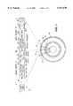
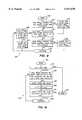
- FIG. 1is a diagram of a storage disk showing a greatly enlarged and linearized depiction of a servo sector and data sector within a circular track format of the FIG. 3 hard disk drive.
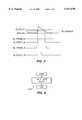
- FIG. 2is a graph of a TA and certain threshold levels and a TA detect signal generated during the TA recovery modes of the present invention, graphed along a common time base axis.
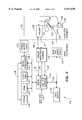
- FIG. 3is an electrical block diagram of a hard disk drive incorporating TA recovery modes in accordance with the present invention.
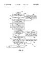
- FIG. 4is a flowchart of a TA recovery method carried out by the FIG. 3 disk drive during data reads in accordance with the present invention.
- FIG. 5is a flowchart of a simple retry subroutine which may be invoked within the FIG. 4 process flow.
- FIG. 6is a flowchart of a soft retry subroutine which may be invoked within the FIG. 4 process flow.
- FIG. 7is a flowchart of an error correction subroutine which may be invoked within the FIG. 4 process flow.
- FIG. 8is a flowchart of a minimize TA window with fast feedback subroutine which may be invoked within the FIG. 4 process flow.
- FIG. 9is a flowchart of a subroutine enabling TA recovery modes based on a minimized TA window which may be invoked within the FIG. 4 process flow.
- FIG. 10is a flowchart of a subroutine enabling a soft retry followed by an optional retry with a chunk flip mode which may be invoked within the FIG. 4 process flow.
- FIG. 11is a flowchart of a subroutine which performs retries while forcing data sync, which may be invoked within the FIG. 4 process flow.
- the present inventionoperates upon a premise that data recovery from TAs is not performed in real time, because any modifications made to the data channel to enhance data recovery from a TA may cause performance degradation during otherwise normal channel operations. Moreover, if a TA is severe, that detected situation alone causes a determination that some types of channel modifications are required for effective data recovery, and those modifications and subsequent detection efforts cannot be carried out during real time operation of the disk drive.
- a TA detect signal(TA -- Detect -- A) is generated within the analog read channel 110 by monitoring a Baseline amplitude level at e.g. the preamplifier 108 and signaling onset of a TA over a path 74 to the analog read channel chip 110.
- the analog read channel chip 110then asserts the TA -- Detect -- A signal on a path 72 to a drive digital controller ASIC 112 when baseline signal amplitude exceeds a predetermined threshold TA -- Assert.
- the TA -- Detect -- A signalis asserted over path 72 until the analog signal falls below a predetermined TA -- Deassert threshold level, lower than the TA -- Assert threshold.
- the TA -- Detect -- A signalresults in calling and execution of one or more of the FIGS. 4-11 TA recovery subroutines by a drive microprocessor 114.
- the digital data controller 112essentially captures and marks the time of the TA detect signal and the corresponding physical (byte) location of the TA within the format of the data storage track 12 being followed during read back operations of the disk drive 100. From TA physical location information in light of a known track format and instantaneous rotational position of the TA, one or more of a plurality of available data recovery processes may be selected and progressively applied under firmware control by the microprocessor 114 in order to attempt a data recovery.
- the digital controller ASIC 112generates a data recovery TA -- Strobe -- B signal which is passed back to the analog read channel 110 over a path 76 in order to signal the analog channel 110 when to activate and apply a particular data recovery process during a subsequent revolution of disk 10 past the TA site.
- the digital controllermay direct the analog read channel to modify one or more of the following channel performance parameters:
- AGC preset modea predetermined value, which may be invoked if the TA occurs in the middle of a data preamble field from which AGC control values are derived
- the drive firmwaremay invoke one of the following TA recovery modes at the drive microcontroller level:
- a rotating data storage disk 10has at least one formatted data storage surface defining a multiplicity of concentric data tracks 12.
- Each track 12is divided up into an alternating pattern of servo sectors or "spokes" 14, and data regions 16.
- the tracks 12are banded together into a plurality of radial data zones, such that a data transfer rate is optimized for a minimum-radius track within each zone.
- a head transducer/slider structure 18"flies" on an air bearing adjacent to the data recording surface.
- the structure 18may include a relatively wide inductive write element 20 and a relatively narrow MR read element 22.
- the head/slider structure 18is typically positioned by a rotary voice coil actuator 102 referenced to a base 104, and an offset or skew is present between the read element 22 and the write element 20, depending upon radial position of the head 18 relative to the disk 10.
- each servo spoke 14may include a DC erase gap 30, a servo AGC field 32, a servo PLL field 34, a servo address sync field 38 (also known as a "servo address mark"), a spoke address field 40, a write burst pattern field 42, and a read burst pattern field 44 (which is offset from the write burst pattern field by the skew angle present at the particular radius of the illustrated track 12).
- a write-splice region 46marks beginning of the data sector 16.
- the data sector 16may include an AGC field 50 and a data PLL field 52 forming a preamble 54, a data sync pattern field 56 (also known as a "data address mark pattern"), a user data field 58 for storing a known number of user data bytes, and an ECC (and cross-check) field 60 at the end of the data field 58.
- the user data field 52will hold a standard block size of data, such as 512 or 1024 bytes.
- the servo spokes 14will split up at least some of the data fields 52, and each data field will include multiple embedded servo spokes.
- FIG. 3sets forth a high level block diagram of a hard disk drive 100 incorporating the principles of the present invention.
- FIG. 3shows that the disk drive 100 is divided into an electromechanical head/disk assembly and a drive electronics section which is preferably contained on a small printed circuit board mounted to one major wall of the head/disk assembly.
- the head/disk assemblyincludes and registers relative positions of the disk 10 and the head structure 18 via a base 104.
- the headis positioned by the rotary voice coil actuator assembly 102 which is mounted to the base 104.
- a spindle motor 106is also mounted to the base 104, and the motor 106 rotates the disk 10 at a predetermined constant angular velocity. While only one disk 10 is shown in FIG. 4, those skilled in the art will appreciate that multiple disks may be stacked on a spindle assembly including the spindle motor 106. In that case, the actuator assembly 102 would include a stack of heads and head arms, each head being associated with a separate data storage surface of an adjacently facing disk. The heads 18 are attached to head arms by load beams and flexures which provide a spring preload function to bias the heads 18 towards the facing disk surfaces.
- Rotation of the disk(s) 10 by motor 106creates an air bearing between the head and the adjacent surface, and the head flies on this air bearing in close proximity to the data surface. It is in this regime that thermal asperities occur, because the head 18 is relatively very close to the disk surface (e.g. ⁇ 1-2 microinches separation).
- the preamplifier and head selector circuit 108is also provided within the head/disk assembly in order to be as close to the transducers 18 as practical in order to minimize noise pickup.
- the drive electronicsincludes the analog write/read channel chip 110, a digital controller and interface chip 112, at least one embedded standard microprocessor 114 (also including "glue" logic for the disk drive application), a head position servo controller chip 116, a data buffer array 118, a spindle motor controller 120, a flash ROM 122, a static RAM 124, and an EEPROM 126.
- the drive electronicsincludes a number of bus structures including a wideband digital bus 128 between the digital controller 112, microprocessor 114, flash ROM 122, and SRAM 124.
- An interface bus 130implementing a conventional bus structure such as a SCSI bus, leads from the digital drive controller 112 to a host computing environment (not shown).
- a serial bus 132interconnects the digital drive controller 112 and the analog write/read channel chip 110. This bus 132 carries the TA detect signal from the analog channel chip 110 to the digital drive controller chip 112, and the TA strobe signal in the opposite direction.
- busesinclude a bus 134 between the digital drive controller and the data buffer 118 and head position servo controller 116, a bus 136 between the microprocessor 114 and the spindle motor controller 120, and a serial bus 138 between the microprocessor 114 and the EEPROM 126.
- a separate servo microcontroller or digital signal processor (DSP)may also be included for control of the head position servo loop, and in that event, the DSP may be connected between the digital controller ASIC 112 and the head position servo controller 116 control via a suitable bus structure, not shown.
- This firmwareis stored in a suitable memory location, such as the flash ROM 122 and called and executed by the microprocessor 114 when a TA is detected by the read channel chip 110.
- the global recovery algorithm for TAsis customized to the location of each detected TA and the type of operation being performed by the disk drive. TA recovery is invoked for each disk block in error on a given track. TAs are detected by the analog read channel chip 110, and a window, TA -- detect, in time is captured. As shown in the FIG. 2 graph, this TA -- detect window describes the physical boundaries of the TA within the track format. The TA -- detect window is provided to the firmware so that one of a plurality of recovery modes may be invoked.
- the read recovery algorithm for TA recoveriesmakes use of many recovery modes, some of which are adapted exclusively for TA recovery.
- FIG. 4illustrates a read recovery algorithm in accordance with principles of the present invention.
- the retry algorithmmay include a series of soft retries during multiple rotations of the storage disk 10 over the TA site until the data is recovered, or until all of the alternative retries and recovery methods have been attempted. Each soft retry utilizes a unique recovery method. Some soft retries will be conditional, based on the determined location of the TA. The series of soft retries will iterate up to a maximum number of passes over the TA site by the head 18, the maximum number being set in a mode page location in firmware memory. Within each pass, soft retries will be performed at a number of different servo offsets, starting with an offset of zero. Offsetting of the head 18 will be combined with other recovery methods on each soft retry.
- bias current of the MR read element 22is switched to a next value. All soft retries in the subsequent pass over the TA site by the element 22 will use the next MR bias current value. If the number of passes exceeds the number of available bias current values, then the bias current value wraps around to the original bias current value. At the end of all passes during TA recovery mode, the bias current for MR element 22 is restored to its original or nominal value. Any soft retry which recovers the data causes the algorithm to stop performing soft retries immediately, and the routine is exited by the microprocessor 114.
- the algorithmis continued by the microprocessor 114 until the number of retries is exhausted or the recovery time expires.
- the TA recovery algorithmbegins at an entry state 200.
- a step 202immediately follows entry which enables a Force Sync retries subroutine and sets the number of iterations through the FIG. 4 loop to zero.
- a step 204determines whether the number of iterations through the FIG. 5 loop are less than the predetermined maximum Read Retry count value. If so, the algorithm has completed without recovering the data, and a "done" state 206 is reached, thereby ending the TA recovery effort for the present TA. If not, a step 208 is reached at which the offset index is set to zero.
- a logical step 210is reached at which the offset index is tested against a maximum number of offsets. If the offset index is greater than or equal to the maximum number, a step 212 is reached at which a switch is made to the next MR bias current step. A step 214 then increments the number of iterations, and returns to step 204 for a repeat pass through the FIG. 4 flow diagram. If the offset index is less than the number of offsets, as tested at the logical step 210, a step 216 is reached. The step 216 enables a next Read Offset. A step 218 then invokes a Simple Retry subroutine (FIG. 5) to capture the initial TA window, WIN simple.
- FOG. 5Simple Retry subroutine
- FIG. 5shows that the Simple Retry subroutine essentially comprises a call to the Soft Retry subroutine (FIG. 6).
- logical step 220calls a Fast DC Feedback subroutine (FIG. 8) and selects the minimized TA window, WiNmin. If these steps recover the data, the process has successfully completed, and the done state 206 is reached. If not, further recovery modes based on the minimized TA window are invoked at a step 222.
- a logical step 224determines whether a data sync time-out has occurred, and further determines if the minimized TA window WINmin intersects the data sync field 56. If so, a Force Sync Retries subroutine (FIG. 11) is called and executed at a step 226. If the data is then recovered, the done state 206 is reached. If not, a step 228 is reached which disallows any further Force Sync retries during continuation of the recovery process, and a step 230 is reached which increments to the next offset index and returns process flow to the step 210.
- FOG. 8Fast DC Feedback subroutine
- a step 232is reached which performs a soft retry followed by an optional soft retry after calling the Chunk Flip subroutine.
- Step 234extends the minimized window WinMin to the end of the data block having the TA, disables the zero-threshold mode and PLL coast mode, and enables the Fast DC feedback mode. Then, a step 236 is reached. At step 236 an soft retry is attempted, followed by an optional soft retry with chunk flip mode. If the data is recovered, the done state 206 is reached. If not, recovery process flow continues to step 230.
- a number of the recovery modes described in the FIG. 4 recovery processinclude calling a Soft Retry subroutine.
- the Soft Retry subroutineis shown in FIG. 6.
- the read operationis retried for the block, with hardware auto-retries and hardware ECC disabled. If the retry encountered an ECC error, then firmware ECC correction may be invoked, FIG. 7.
- the software retryis careful to check a number of conditions before applying firmware ECC correction.
- the ECC errormust be the "primary" error. Most other error conditions such as Data Sync Time-out take precedence over an ECC error.
- Second, a Disable Correction status from the applicable SCSI interface mode pagemust not be set.
- a software EDC checkis performed to validate the correction.
- the flowchart illustrating the Soft Retry subroutinebegins at an entry state 240.
- a process step 242causes a hardware retry to be attempted with the hardware ECC function and the auto-retries function disabled.
- a logical node 244detects whether the hardware retry is successful. If so, a data-recovered state 246 is reached and the TA recovery algorithm is exited. If not, a logical step 248 determines if a TA has been detected. If yes, the TA window, TA -- Detect, shown in FIG. 2, is captured at a step 250.
- TA -- Detectattempts data recovery using the TA window as a location hint for the ECC process as shown in FIG. 7. If the ECC process is not successful, as tested at a logical step 264, the unrecovered state 254 is reached. However, if the ECC process is successful, a step 266 is reached at which a manual EDC step is carried out. A logical step 268 then checks whether the manual EDC step failed. If so, the unrecovered state 254 is reached; otherwise, the recovered state 246 is reached. States 246 and 254 mark subroutine exit states for returns to the main algorithm of FIG. 5.
- Another step 218calls a Simple Retry subroutine, shown in FIG. 5.
- the Simple Retry subroutine 218attempts to recover the data using a soft retry, possibly in combination with enhanced ECC, Read-Offsetting, and/or MR bias current switching (depending upon the number of prior iterations through the FIG. 4 recovery algorithm). If the data is not recovered by Simple Retry, the TA window TA -- Detect is captured in WINsimple, and the recovery algorithm of FIG. 4 continues.
- FAST DC feedback modeis used to try to minimize duration of the TA window.
- Fast DC modereduces the time duration of the TA detection window shown in FIG. 2 as waveform TA -- Detect -- B. If Fast DC Feedback is effective in minimizing the window, it will be enabled for use in conjunction with other recovery modes, if required.
- Skip Spoke modeis configured accordingly for the selected TA window, i.e. if the TA window intersects a servo spoke 14, then skip spoke mode will be enabled for that spoke in subsequent soft retries.
- the Window Minimization subroutinebegins at an entry state 280.
- a step 282sets the WINmin value to be equal to the WINsimple value.
- a step 284determines if the WINsimple window intersects a servo spoke 14. If so, a step 286 enables a Skip Spoke subroutine using the WINsimple window to determine which spoke will be skipped. If not, or upon completion of step 286, a step 288 is reached which enables the FAST DC Feedback mode using the WINsimple window as the data recovery window.
- a step 290calls the Soft Retry subroutine and a new window WINfastDC is captured.
- a step 292is then reached which disables the FAST DC Feedback mode and which checks the results of the soft retry. If the data is recovered, the done state 206 is reached. If the data is not recovered, a step 294 is reached.
- the logical step 294tests whether the size of the minimized window WINmin minus the size of the new window WINfastDC is greater than a minimum threshold value. If so, the minimized window WINmin is made equal to the new window WINfastDC at a step 296, and a step 298 enables the Fast DC Feedback mode for any subsequent retries. If not, or after completion of step 298, a step 300 is reached which determines whether the WINmin window intersects a servo spoke 14. If so, a step 302 is reached which enables the Skip Spoke mode by using the WINmin window location to determine the identification of the particular servo spoke 14. If not, the Skip Spoke mode is disabled at a step 306.
- a step 304is reached which sets up the WINmin window as the recovery window for subsequent TA recovery retries, and a continue state 308 is reached at which the Window Minimization subroutine is left and program flow returns to the main TA recovery algorithm of FIG. 4.
- AGC Preset modeis used if the window WINmin is within the AGC Preset portion 50 of the data sector preamble.
- the AGC Preset modeis configured using a predetermined value based upon a particular data zone of-the track containing the TA.
- PLL coast modeis used if the window WINmin intersects a data sync field 56 or a user data block 58, providing the window WINmin does not also intersect a servo spoke 14 or the data preamble fields 50, 52 or 54.
- a Zero Threshold recovery modeis used if the window WINmin intersects a data sync field 56 or the data block field 58 and the beginning of the data preamble (fields 50, 52 or 54), providing the window WINmin does not also intersect a data sync field 56 or a data block field 58.
- FIG. 9is a flowchart of a subroutine for enabling TA recovery modes based upon use of the minimized TA window WINmin.
- This subroutinebegins at an entry state 320.
- a logical step 322determines whether the minimized window WINmin intersects the AGC field 50 within the data preamble of a data sector 16. If so, a step 324 enables the AGC Preset mode by using the WINmin location and a preset derived from the particular data zone including the track 12 having the TA. If not, or upon completion of step 324, a step 326 is reached which determines whether the minimized window intersects the data sync field 56 or the data block 58.
- a logical step 328is reached which determines whether the minimized window WINmin intersects the servo spoke 14 or the data preamble (fields 50-54). If not, a step 330 is reached which enables the PLL Coast mode using the WINmin window as a gate, and a continue state 332 is reached. The state 332 is reached directly from step 328 if the decision reached is true.
- step 334determines whether the minimized window WINmin intersects the data preamble before the AGC portion. If so, a step 336 is reached which enables the Zero Threshold recovery mode using WINmin as a gate. Then, the continue state 332 is reached. The continue state is reached directly from step 334 if its logical result is negative.
- the subroutine supporting step 232, Soft Retry with Optional Retry with Chunk Flipis illustrated in FIG. 10. An additional retry is performed with Chunk Flip mode if the minimized window WINmin intersects the Chunk Align portion 54 of data preamble and a data sync time-out error has occurred.
- This subroutine 232includes an entry state 340 leading to a first step 342 which performs a soft retry by calling the FIG. 6 Soft Retry subroutine. If the soft retry is successful, the done state 206 is reached. If not, a step 344 is reached which tests whether the minimized window WINmin intersect the Chunk Align field 54 and whether a data sync timeout has occurred.
- a continue state 346is reached which marks an exit from this subroutine. If so, a step 348 is reached which enables the Chunk Flip mode. Then, another soft retry is attempted at a step 350. A step 352 is then reached which disables the Chunk Flip mode, and which checks the result of the soft retry. If successful, the done state 206 is reached. If not successful, the TA recovery algorithm is continued at state 346.
- Force Sync mode 226is applied. Force Sync mode 226 is shown as a subroutine in FIG. 11. Force Sync mode retries are only permitted to execute once per disk block, due to time constraints. The Force Sync mode 226 subroutine executes up to e.g. 30 consecutive soft retries for each member of e.g. seven potential Force Sync offset values. If the TA window WINmin intersects the Chunk Align field 54 of the data preamble, the a second soft retry using Chunk Flip mode is carried out.
- the Force Sync mode subroutine 226begins at an entry state 360.
- a step 362presets a Force Sync index value to zero, marking the first pass through this subroutine 226.
- a logical step 364determines whether the Force Sync index value is less than a maximum number, e.g. 7, of Force Sync index values. If not, meaning that Force Sync retries have been attempted at the e.g. 7 possible sync locations in the format, a step 366 turns off the Force Sync mode, and a continue state 368 is reached at which this subroutine is exited. If the present Force Sync index value is below the maximum value, as tested by step 364, a step 370 is reached.
- Step 370enables the Force Sync mode using the WINmin location and the FSYNC value at the current index number.
- a counting step 372is then reached.
- the Force Sync iteration valueis initially set to zero in step 372, and is incremented during each pass through step 380.
- a logical node 374tests whether the Force Sync iteration number is less than a maximum number of Force Sync iterations. If not, a step 376 increments to a next Force Sync index number, and a return is made to step 364. If so, a step 377 calls the Do Soft Retry Followed by Optional Soft Retry with Chunk Flip mode subroutine 232 which executes. Following execution of subroutine 232, the result is tested at step 377. If the data is recovered, the TA recovery algorithm done state 206 is reached. If the data remains unrecovered at step 377, a step 380 increments to the next Force Sync iteration value, and a return is made to the step 374.
- ECC correction process flowstarts at an entry point 402 and progresses to a process block 404 which sets an interleave variable to an initial interleave value of zero, i.e. the first ECC interleave to be processed.
- a logical node 406determines if the interleave variable is less than X, which represents a set number of interleaves based upon the ECC data design, such as two, three or four. If the set number has been reached, an ECC end node 408 is reached. If not, a logical node determines whether the TA error burst length is greater than a maximum burst error length correction capability of the ECC system employed by the drive 100.
- an ECC end node 408is reached, and program flow returns to the FIG. 4 TA correction algorithm. If not, a process step 414 is reached which modifies the recovered ECC error syndrome to account for erasure.
- a logical node 416determines if all syndromes for the current ECC interleave are equal to zero, meaning that an error has not been detected in the current interleave by the ECC system. If so, ECC processing is continued at step 430 which increments to a next ECC interleave. If not, a logical node 418 is reached which determines whether the number of redundancy symbols for the current interleave are less than two after the thermal asperity is accounted for.
- Step 420determines the error location via the error locator polynomial, via conventional ECC techniques not particularly pertinent to the present invention.
- a step 422is reached.
- Step 422determines the remaining ECC error burst detection power for the corrupted data block after the TA and any other error are accounted for.
- a logical node 424determines if the remaining detection power is less than one. If so, the ECC process is terminated at end node 408. If not, a process step 426 is reached. Step 426 determines the error locations and error values, again by employing any suitable conventional ECC methodology (and may include cross-check processes to ensure against miscorrection of data).
- a step 428then causes the corrupted data block to be corrected in the cache buffer memory 118.
- a step 430increments the interleave count by one unit, and returns process flow to step 406 for the next ECC interleave. This process continues until all ECC interleaves of the data block have been processed.
- Block 258follows a subset of the steps graphed in FIG. 7 and omits steps 410, 414, and 418; and, includes steps 402, 404, 406, 408, 416, 420, 422, 424, 426, 428 and 430.
- the Simple Retrycaptures a "raw" TA -- Detect -- A window, directly from the analog channel 110 by reference to the TA -- Assert threshold on the rising edge of the TA, and by reference to the TA -- Deassert threshold on the falling edge of the TA.
- TA -- Strobe -- Bis generated by the digital controller ASIC 112 based on WINsimple (duration of TA -- Detect -- A), and a Fast DC Feedback retry captures the next TA detection window, TA -- Detect -- B which has a rising edge which is likely to be aligned to the rising edge of TA -- Detect -- A, and a trailing edge occurring significantly earlier than TA -- Detect -- A, and a period of WINfastDC.
- the WiNsimple periodis compared to the WINfastDC period, and the smaller window, TA -- Detect -- A, or TA -- Detect -- B, becomes WINmin.
- the method of the present inventionprovides a comprehensive approach for recovering data initially corrupted by a thermal asperity.
- a more powerful ECC recovery algorithmmay be invoked (since conventional ECC processes have to determine error burst location as well as values).
- the TA location informationenables the recovery process to select a read channel modification which maximizes the probability of data recovery for different TA locations.
- the present approachprovides a data recovery method for a TA otherwise corrupting a data sync field needed for PLL synchronization before being able to read back and recover the data block.
Landscapes
- Engineering & Computer Science (AREA)
- Signal Processing (AREA)
- Digital Magnetic Recording (AREA)
- Signal Processing For Digital Recording And Reproducing (AREA)
- Recording Or Reproducing By Magnetic Means (AREA)
Abstract
Description
Claims (23)
Priority Applications (6)
| Application Number | Priority Date | Filing Date | Title |
|---|---|---|---|
| US08/734,782US5917670A (en) | 1996-10-15 | 1996-10-15 | Method for recovering data from disk with magneto-resistive head in presence of thermal asperities |
| EP97910142AEP0868716A4 (en) | 1996-10-15 | 1997-10-09 | Method for recovering data from disk with magneto-resistive head in presence of thermal asperities |
| JP10518621AJP2000502485A (en) | 1996-10-15 | 1997-10-09 | Method for recovering data from disk using magnetoresistive head in case of thermal irregularities |
| AU47595/97AAU4759597A (en) | 1996-10-15 | 1997-10-09 | Method for recovering data from disk with magneto-resistive head in presence of thermal asperities |
| KR1019980704463AKR19990072132A (en) | 1996-10-15 | 1997-10-09 | Method for recovering data from disks with magnetoresistive heads in the presence of thermal esp |
| PCT/US1997/018810WO1998016918A1 (en) | 1996-10-15 | 1997-10-09 | Method for recovering data from disk with magneto-resistive head in presence of thermal asperities |
Applications Claiming Priority (1)
| Application Number | Priority Date | Filing Date | Title |
|---|---|---|---|
| US08/734,782US5917670A (en) | 1996-10-15 | 1996-10-15 | Method for recovering data from disk with magneto-resistive head in presence of thermal asperities |
Publications (1)
| Publication Number | Publication Date |
|---|---|
| US5917670Atrue US5917670A (en) | 1999-06-29 |
Family
ID=24953054
Family Applications (1)
| Application Number | Title | Priority Date | Filing Date |
|---|---|---|---|
| US08/734,782Expired - Fee RelatedUS5917670A (en) | 1996-10-15 | 1996-10-15 | Method for recovering data from disk with magneto-resistive head in presence of thermal asperities |
Country Status (6)
| Country | Link |
|---|---|
| US (1) | US5917670A (en) |
| EP (1) | EP0868716A4 (en) |
| JP (1) | JP2000502485A (en) |
| KR (1) | KR19990072132A (en) |
| AU (1) | AU4759597A (en) |
| WO (1) | WO1998016918A1 (en) |
Cited By (45)
| Publication number | Priority date | Publication date | Assignee | Title |
|---|---|---|---|---|
| US6084734A (en)* | 1997-12-08 | 2000-07-04 | Maxtor Corporation | Data recovery using targeted ECC correction |
| US6119261A (en)* | 1998-03-17 | 2000-09-12 | Quantum Corporation | Method for recovering data from disk with a dynamic erasure offset ECC data recovery protocol |
| US6122131A (en)* | 1997-09-12 | 2000-09-19 | Quantum Corporation | Adaptively-controlled disk drive assembly |
| US6130793A (en)* | 1996-09-30 | 2000-10-10 | Fujitsu Limited | Thermal asperity detection method, thermal asperity compensation method, magnetic disk unit and retry method therefor |
| US6185716B1 (en)* | 1998-01-30 | 2001-02-06 | Maxtor Corporation | Dual detector read channel with semi-soft detection |
| US6191902B1 (en)* | 1997-03-04 | 2001-02-20 | Fujitsu Limited | Magnetic disk apparatus and magnetic disk medium |
| US6262859B1 (en)* | 1998-08-11 | 2001-07-17 | Samsung Electronics Company | Method and apparatus for providing servo information on a disk in a hard drive assembly |
| US6307719B1 (en) | 1999-11-17 | 2001-10-23 | Maxtor Corporation | Suspension assembly with adjustable gramload |
| US20020048112A1 (en)* | 2000-09-14 | 2002-04-25 | Chu Sang Hoon | Servo defect management scheme in hard disk drives |
| US6414806B1 (en) | 2000-10-02 | 2002-07-02 | International Business Machines Corporation | Method for thermal asperity detection and compensation in disk drive channels |
| US6429994B1 (en) | 1998-08-14 | 2002-08-06 | Samsung Electronics Co., Ltd | Method and apparatus for providing servo gain linearization for a magneto-resistive head |
| US6441988B2 (en) | 1998-10-07 | 2002-08-27 | Samsung Electronics Co., Ltd. | Method and apparatus for reducing acoustic noise in a hard disk drive |
| US6501613B1 (en) | 1999-12-15 | 2002-12-31 | Samsung Electronics Co., Ltd. | Generalized Fourier seek method and apparatus for a hard disk drive servomechanism |
| US6549364B1 (en) | 1999-12-15 | 2003-04-15 | Samsung Electronics Co., Ltd. | Optimization method and apparatus for a generalized fourier seek trajectory for a hard disk drive servomechanism |
| US6587296B1 (en) | 2000-07-21 | 2003-07-01 | Texas Instruments Incorporated | Capacitor bias recovery methodology |
| US20030214747A1 (en)* | 2002-05-14 | 2003-11-20 | Debasis Baral | Servo writing method for hard disk drives |
| US6657803B1 (en) | 1999-11-22 | 2003-12-02 | Seagate Technology Llc | Method and apparatus for data error recovery using defect threshold detector and viterbi gain |
| US6687079B1 (en) | 1999-10-08 | 2004-02-03 | Samsung Electronics Co., Ltd | Apparatus and method for providing servo gain linearization for a magneto-resistive head |
| US6700731B2 (en) | 2001-05-31 | 2004-03-02 | Samsung Electronics Co., Inc. | In-situ linearization of magnetic read/write head transducer position error signal |
| US6704354B1 (en) | 1998-10-16 | 2004-03-09 | Samsung Electronics Co., Ltd. | Method and apparatus of providing adaptive equalization using sign permutation filtering |
| US6744590B2 (en) | 2000-09-14 | 2004-06-01 | Samsung Electronics Co., Inc. | Seek trajectory adaptation in sinusoidal seek servo hard disk drives |
| US6751034B1 (en) | 2000-07-19 | 2004-06-15 | Texas Instruments Incorporated | Preamplifier read recovery parade |
| US6754015B2 (en) | 2002-03-29 | 2004-06-22 | Seagate Technology Llc | MR heads thermal asperity cancellation |
| US6762902B2 (en) | 2000-12-15 | 2004-07-13 | Samsung Electronics Co., Ltd. | Time-varying, non-synchronous disturbance identification and cancellation in a rotating disk storage device |
| US6791778B2 (en) | 2000-09-14 | 2004-09-14 | Samsung Electronics Co., Inc. | Method and apparatus to detect and manage servo sectors with defect on servo pattern area in hard disk drives |
| US6801384B2 (en) | 2000-09-14 | 2004-10-05 | Samsung Electronics Co., Ltd. | Voltage-constrained sinusoidal seek servo in hard disk drives |
| US20040250196A1 (en)* | 2003-06-04 | 2004-12-09 | Hassner Martin Aureliano | Method for correcting a burst of errors plus random errors |
| US20050050425A1 (en)* | 2003-06-02 | 2005-03-03 | Matsushita Electric Industrial Co. Ltd. | Error correction method and apparatus for interleaved data |
| US7158330B2 (en) | 2001-11-08 | 2007-01-02 | Samsung Electronics Co., Ltd. | Method and apparatus for servo track writing by track following on a dedicated servo disk on a fluid spindle bearing |
| US7212364B1 (en)* | 2004-01-31 | 2007-05-01 | Western Digital Technologies, Inc. | Servo writing a disk drive by synchronizing a servo write clock in response to a sync mark reliability metric |
| US7330327B1 (en) | 2004-06-23 | 2008-02-12 | Western Digital Technologies, Inc. | Servo writing a disk drive by writing discontinuous spiral tracks to prevent overheating |
| US7333280B1 (en) | 2004-08-03 | 2008-02-19 | Western Digital Technologies, Inc. | Servo writing a disk drive by synchronizing a servo write clock to a reference pattern on the disk and compensating for repeatable phase error |
| US7333290B1 (en) | 2006-08-03 | 2008-02-19 | Western Digital Technologies, Inc. | Magnetic disk in a disk drive and method having improved null servo burst phasing |
| US7391583B1 (en) | 2006-07-27 | 2008-06-24 | Western Digital Technologies, Inc. | Fault tolerant sync mark detection while servo writing a disk drive from spiral tracks |
| US20080165444A1 (en)* | 2007-01-05 | 2008-07-10 | Broadcom Corporation, A California Corporation | Baseline popping noise detection circuit |
| US7440210B1 (en) | 2004-06-23 | 2008-10-21 | Western Digital Technologies, Inc. | Servo writing a disk drive by writing multi-bit sync marks in spiral tracks for improved servo writing |
| US20090147390A1 (en)* | 2007-12-10 | 2009-06-11 | Samsung Electronics Co., Ltd. | Detecting head/disk contact using timing jitter |
| US7859782B1 (en) | 2008-05-18 | 2010-12-28 | Western Digital Technologies, Inc. | Selecting highest reliability sync mark in a sync mark window of a spiral servo track crossing |
| US8611031B1 (en) | 2012-08-16 | 2013-12-17 | Western Digital Technologies, Inc. | Methods and devices for adaptive margining |
| US8687313B2 (en) | 2011-06-23 | 2014-04-01 | Western Digital Technologies, Inc. | Disk drive mapping out data tracks to avoid thermal asperities |
| US8694841B1 (en)* | 2012-06-20 | 2014-04-08 | Western Digital Technologies, Inc. | Methods and devices for preventing potential media errors from growing thermal asperities |
| US8773801B2 (en) | 2010-10-21 | 2014-07-08 | HGST Netherlands B.V. | Magnetic-recording head with first thermal fly-height control element and embedded contact sensor element configurable as second thermal fly-height control element |
| US20150154065A1 (en)* | 2013-12-04 | 2015-06-04 | Seagate Technology Llc | Adaptive read error recovery for memory devices |
| US20160043829A1 (en)* | 2014-08-11 | 2016-02-11 | Qualcomm Incorporated | Devices and methods for data recovery of control channels in wireless communications |
| US9378083B2 (en) | 2013-12-04 | 2016-06-28 | Seagate Technology Llc | Adaptive read error recovery for memory devices |
Families Citing this family (3)
| Publication number | Priority date | Publication date | Assignee | Title |
|---|---|---|---|---|
| JP3998307B2 (en)* | 1997-12-25 | 2007-10-24 | 富士通株式会社 | Magnetic disk device and error correction method for magnetic disk device |
| JP3532112B2 (en)* | 1999-02-15 | 2004-05-31 | 松下電器産業株式会社 | Fixed magnetic recording device |
| US6724553B2 (en)* | 2001-03-26 | 2004-04-20 | Samsung Electronics Co., Ltd. | Method and apparatus for generating the optimum read timing for read and write offset of a magneto resistive head |
Citations (10)
| Publication number | Priority date | Publication date | Assignee | Title |
|---|---|---|---|---|
| US3975772A (en)* | 1975-06-02 | 1976-08-17 | International Business Machines Corporation | Double shielded magnetorestive sensing element |
| US5122915A (en)* | 1990-09-26 | 1992-06-16 | Minnesota Mining And Manufacturing Company | Low-noise preamplifier for magneto-resistive heads |
| US5233482A (en)* | 1991-07-31 | 1993-08-03 | International Business Machines Corporation | Thermal asperity compensation for PRML data detection |
| US5241546A (en)* | 1991-02-01 | 1993-08-31 | Quantum Corporation | On-the-fly error correction with embedded digital controller |
| US5255136A (en)* | 1990-08-17 | 1993-10-19 | Quantum Corporation | High capacity submicro-winchester fixed disk drive |
| US5497111A (en)* | 1994-12-22 | 1996-03-05 | International Business Machines Corporation | Peak detection circuit for suppressing magnetoresistive thermal asperity transients in a data channel |
| US5537034A (en)* | 1995-05-19 | 1996-07-16 | Quantum Corporation | Method for mapping thermal asperities of a magnetic recording surface in data storage device |
| US5680265A (en)* | 1995-09-05 | 1997-10-21 | Mitsubishi Denki Kabushiki Kaisha | Circuit for detecting contact of MR head with disk surface |
| US5701314A (en)* | 1995-12-21 | 1997-12-23 | Cirrus Logic, Inc. | On-the-fly error correction using thermal asperity erasure pointers from a sampled amplitude read channel in a magnetic disk drive |
| US5754355A (en)* | 1995-09-21 | 1998-05-19 | International Business Machines Corporation | Disk drive apparatus and read error recovery method in a disk drive apparatus |
Family Cites Families (2)
| Publication number | Priority date | Publication date | Assignee | Title |
|---|---|---|---|---|
| US5379162A (en)* | 1993-08-19 | 1995-01-03 | International Business Machines Corporation | Customized data recovery procedures selected responsive to readback errors and transducer head and disk parameters |
| US5696643A (en)* | 1995-04-20 | 1997-12-09 | International Business Machines Corporation | Disk drive apparatus and read error recovery method in a disk drive apparatus |
- 1996
- 1996-10-15USUS08/734,782patent/US5917670A/ennot_activeExpired - Fee Related
- 1997
- 1997-10-09WOPCT/US1997/018810patent/WO1998016918A1/ennot_activeApplication Discontinuation
- 1997-10-09KRKR1019980704463Apatent/KR19990072132A/ennot_activeWithdrawn
- 1997-10-09EPEP97910142Apatent/EP0868716A4/ennot_activeWithdrawn
- 1997-10-09AUAU47595/97Apatent/AU4759597A/ennot_activeAbandoned
- 1997-10-09JPJP10518621Apatent/JP2000502485A/ennot_activeCeased
Patent Citations (10)
| Publication number | Priority date | Publication date | Assignee | Title |
|---|---|---|---|---|
| US3975772A (en)* | 1975-06-02 | 1976-08-17 | International Business Machines Corporation | Double shielded magnetorestive sensing element |
| US5255136A (en)* | 1990-08-17 | 1993-10-19 | Quantum Corporation | High capacity submicro-winchester fixed disk drive |
| US5122915A (en)* | 1990-09-26 | 1992-06-16 | Minnesota Mining And Manufacturing Company | Low-noise preamplifier for magneto-resistive heads |
| US5241546A (en)* | 1991-02-01 | 1993-08-31 | Quantum Corporation | On-the-fly error correction with embedded digital controller |
| US5233482A (en)* | 1991-07-31 | 1993-08-03 | International Business Machines Corporation | Thermal asperity compensation for PRML data detection |
| US5497111A (en)* | 1994-12-22 | 1996-03-05 | International Business Machines Corporation | Peak detection circuit for suppressing magnetoresistive thermal asperity transients in a data channel |
| US5537034A (en)* | 1995-05-19 | 1996-07-16 | Quantum Corporation | Method for mapping thermal asperities of a magnetic recording surface in data storage device |
| US5680265A (en)* | 1995-09-05 | 1997-10-21 | Mitsubishi Denki Kabushiki Kaisha | Circuit for detecting contact of MR head with disk surface |
| US5754355A (en)* | 1995-09-21 | 1998-05-19 | International Business Machines Corporation | Disk drive apparatus and read error recovery method in a disk drive apparatus |
| US5701314A (en)* | 1995-12-21 | 1997-12-23 | Cirrus Logic, Inc. | On-the-fly error correction using thermal asperity erasure pointers from a sampled amplitude read channel in a magnetic disk drive |
Non-Patent Citations (5)
| Title |
|---|
| "Disk Drive Interface Guide", Mass Storage Handbook, Chapter 9, pp. 9-3 through 9-158, National Semiconductor Corporation, copyright 1989. |
| Data Sheet, SSI 32R1510BR MR Head Read/Write Device, Silicon Systems, Dec. 1993, copyright 1994.* |
| Data Sheet, VM6130 Magneto Resistive Head, High Performance, Read/Write Preamplifier, VTC Inc., Aug. 1996.* |
| Data Sheet, VM6130 Magneto-Resistive Head, High Performance, Read/Write Preamplifier, VTC Inc., Aug. 1996. |
| Disk Drive Interface Guide , Mass Storage Handbook, Chapter 9, pp. 9 3 through 9 158, National Semiconductor Corporation, copyright 1989.* |
Cited By (51)
| Publication number | Priority date | Publication date | Assignee | Title |
|---|---|---|---|---|
| US6130793A (en)* | 1996-09-30 | 2000-10-10 | Fujitsu Limited | Thermal asperity detection method, thermal asperity compensation method, magnetic disk unit and retry method therefor |
| US6191902B1 (en)* | 1997-03-04 | 2001-02-20 | Fujitsu Limited | Magnetic disk apparatus and magnetic disk medium |
| US6122131A (en)* | 1997-09-12 | 2000-09-19 | Quantum Corporation | Adaptively-controlled disk drive assembly |
| US6147827A (en)* | 1997-12-08 | 2000-11-14 | Maxtor Corporation | Method of correcting read errors in a data storage system using targeted ECC |
| US6084734A (en)* | 1997-12-08 | 2000-07-04 | Maxtor Corporation | Data recovery using targeted ECC correction |
| US6185716B1 (en)* | 1998-01-30 | 2001-02-06 | Maxtor Corporation | Dual detector read channel with semi-soft detection |
| US6119261A (en)* | 1998-03-17 | 2000-09-12 | Quantum Corporation | Method for recovering data from disk with a dynamic erasure offset ECC data recovery protocol |
| US6262859B1 (en)* | 1998-08-11 | 2001-07-17 | Samsung Electronics Company | Method and apparatus for providing servo information on a disk in a hard drive assembly |
| US6429994B1 (en) | 1998-08-14 | 2002-08-06 | Samsung Electronics Co., Ltd | Method and apparatus for providing servo gain linearization for a magneto-resistive head |
| US6441988B2 (en) | 1998-10-07 | 2002-08-27 | Samsung Electronics Co., Ltd. | Method and apparatus for reducing acoustic noise in a hard disk drive |
| US6704354B1 (en) | 1998-10-16 | 2004-03-09 | Samsung Electronics Co., Ltd. | Method and apparatus of providing adaptive equalization using sign permutation filtering |
| US6687079B1 (en) | 1999-10-08 | 2004-02-03 | Samsung Electronics Co., Ltd | Apparatus and method for providing servo gain linearization for a magneto-resistive head |
| US6307719B1 (en) | 1999-11-17 | 2001-10-23 | Maxtor Corporation | Suspension assembly with adjustable gramload |
| US6657803B1 (en) | 1999-11-22 | 2003-12-02 | Seagate Technology Llc | Method and apparatus for data error recovery using defect threshold detector and viterbi gain |
| US6501613B1 (en) | 1999-12-15 | 2002-12-31 | Samsung Electronics Co., Ltd. | Generalized Fourier seek method and apparatus for a hard disk drive servomechanism |
| US6549364B1 (en) | 1999-12-15 | 2003-04-15 | Samsung Electronics Co., Ltd. | Optimization method and apparatus for a generalized fourier seek trajectory for a hard disk drive servomechanism |
| US6751034B1 (en) | 2000-07-19 | 2004-06-15 | Texas Instruments Incorporated | Preamplifier read recovery parade |
| US6587296B1 (en) | 2000-07-21 | 2003-07-01 | Texas Instruments Incorporated | Capacitor bias recovery methodology |
| US6906883B2 (en) | 2000-09-14 | 2005-06-14 | Samsung Electronics Ltd., Co. | Servo defect management scheme in hard disk drives |
| US6801384B2 (en) | 2000-09-14 | 2004-10-05 | Samsung Electronics Co., Ltd. | Voltage-constrained sinusoidal seek servo in hard disk drives |
| US6744590B2 (en) | 2000-09-14 | 2004-06-01 | Samsung Electronics Co., Inc. | Seek trajectory adaptation in sinusoidal seek servo hard disk drives |
| US20020048112A1 (en)* | 2000-09-14 | 2002-04-25 | Chu Sang Hoon | Servo defect management scheme in hard disk drives |
| US6791778B2 (en) | 2000-09-14 | 2004-09-14 | Samsung Electronics Co., Inc. | Method and apparatus to detect and manage servo sectors with defect on servo pattern area in hard disk drives |
| US6414806B1 (en) | 2000-10-02 | 2002-07-02 | International Business Machines Corporation | Method for thermal asperity detection and compensation in disk drive channels |
| US6762902B2 (en) | 2000-12-15 | 2004-07-13 | Samsung Electronics Co., Ltd. | Time-varying, non-synchronous disturbance identification and cancellation in a rotating disk storage device |
| US6700731B2 (en) | 2001-05-31 | 2004-03-02 | Samsung Electronics Co., Inc. | In-situ linearization of magnetic read/write head transducer position error signal |
| US7158330B2 (en) | 2001-11-08 | 2007-01-02 | Samsung Electronics Co., Ltd. | Method and apparatus for servo track writing by track following on a dedicated servo disk on a fluid spindle bearing |
| US6754015B2 (en) | 2002-03-29 | 2004-06-22 | Seagate Technology Llc | MR heads thermal asperity cancellation |
| US20030214747A1 (en)* | 2002-05-14 | 2003-11-20 | Debasis Baral | Servo writing method for hard disk drives |
| US20050050425A1 (en)* | 2003-06-02 | 2005-03-03 | Matsushita Electric Industrial Co. Ltd. | Error correction method and apparatus for interleaved data |
| US7272777B2 (en)* | 2003-06-04 | 2007-09-18 | International Business Machines Corporation | Method for correcting a burst of errors plus random errors |
| US20040250196A1 (en)* | 2003-06-04 | 2004-12-09 | Hassner Martin Aureliano | Method for correcting a burst of errors plus random errors |
| US7212364B1 (en)* | 2004-01-31 | 2007-05-01 | Western Digital Technologies, Inc. | Servo writing a disk drive by synchronizing a servo write clock in response to a sync mark reliability metric |
| US7330327B1 (en) | 2004-06-23 | 2008-02-12 | Western Digital Technologies, Inc. | Servo writing a disk drive by writing discontinuous spiral tracks to prevent overheating |
| US7440210B1 (en) | 2004-06-23 | 2008-10-21 | Western Digital Technologies, Inc. | Servo writing a disk drive by writing multi-bit sync marks in spiral tracks for improved servo writing |
| US7333280B1 (en) | 2004-08-03 | 2008-02-19 | Western Digital Technologies, Inc. | Servo writing a disk drive by synchronizing a servo write clock to a reference pattern on the disk and compensating for repeatable phase error |
| US7391583B1 (en) | 2006-07-27 | 2008-06-24 | Western Digital Technologies, Inc. | Fault tolerant sync mark detection while servo writing a disk drive from spiral tracks |
| US7333290B1 (en) | 2006-08-03 | 2008-02-19 | Western Digital Technologies, Inc. | Magnetic disk in a disk drive and method having improved null servo burst phasing |
| US20080165444A1 (en)* | 2007-01-05 | 2008-07-10 | Broadcom Corporation, A California Corporation | Baseline popping noise detection circuit |
| US20090147390A1 (en)* | 2007-12-10 | 2009-06-11 | Samsung Electronics Co., Ltd. | Detecting head/disk contact using timing jitter |
| US7768728B2 (en)* | 2007-12-10 | 2010-08-03 | Samsung Electronics Co., Ltd. | Detecting head/disk contact using timing jitter |
| US7859782B1 (en) | 2008-05-18 | 2010-12-28 | Western Digital Technologies, Inc. | Selecting highest reliability sync mark in a sync mark window of a spiral servo track crossing |
| US8773801B2 (en) | 2010-10-21 | 2014-07-08 | HGST Netherlands B.V. | Magnetic-recording head with first thermal fly-height control element and embedded contact sensor element configurable as second thermal fly-height control element |
| US8687313B2 (en) | 2011-06-23 | 2014-04-01 | Western Digital Technologies, Inc. | Disk drive mapping out data tracks to avoid thermal asperities |
| US8694841B1 (en)* | 2012-06-20 | 2014-04-08 | Western Digital Technologies, Inc. | Methods and devices for preventing potential media errors from growing thermal asperities |
| US8611031B1 (en) | 2012-08-16 | 2013-12-17 | Western Digital Technologies, Inc. | Methods and devices for adaptive margining |
| US20150154065A1 (en)* | 2013-12-04 | 2015-06-04 | Seagate Technology Llc | Adaptive read error recovery for memory devices |
| US9378083B2 (en) | 2013-12-04 | 2016-06-28 | Seagate Technology Llc | Adaptive read error recovery for memory devices |
| US9397703B2 (en)* | 2013-12-04 | 2016-07-19 | Seagate Technology Llc | Adaptive read error recovery for memory devices |
| US20160043829A1 (en)* | 2014-08-11 | 2016-02-11 | Qualcomm Incorporated | Devices and methods for data recovery of control channels in wireless communications |
| US9379739B2 (en)* | 2014-08-11 | 2016-06-28 | Qualcomm Incorporated | Devices and methods for data recovery of control channels in wireless communications |
Also Published As
| Publication number | Publication date |
|---|---|
| AU4759597A (en) | 1998-05-11 |
| WO1998016918A1 (en) | 1998-04-23 |
| EP0868716A1 (en) | 1998-10-07 |
| JP2000502485A (en) | 2000-02-29 |
| EP0868716A4 (en) | 1999-12-29 |
| KR19990072132A (en) | 1999-09-27 |
Similar Documents
| Publication | Publication Date | Title |
|---|---|---|
| US5917670A (en) | Method for recovering data from disk with magneto-resistive head in presence of thermal asperities | |
| KR100561798B1 (en) | Method and apparatus for recovering data error using fault threshold detector and Viterbi gain | |
| US8014094B1 (en) | Disk drive expediting defect scan when quality metric exceeds a more stringent threshold | |
| US6490691B1 (en) | Error recovery in a disk drive | |
| US8116025B1 (en) | Disk drive executing retry operation after adjusting jog value in response to gain control | |
| US5721816A (en) | Adaptive recovery of read and write errors in a disc drive | |
| US6981205B2 (en) | Data storage apparatus, read data processor, and read data processing method | |
| US7075742B2 (en) | Servo demodulator systems including multiple servo demodulators | |
| US20050013031A1 (en) | Systems for searching for SAM patterns at multiple nominal frequencies | |
| US6119261A (en) | Method for recovering data from disk with a dynamic erasure offset ECC data recovery protocol | |
| US6392831B1 (en) | Identification of defective servo information elements in a disc drive system | |
| US20050013027A1 (en) | Methods for searching for SAM patterns using multiple sets of servo demodulation detection parameters | |
| JPH04219677A (en) | Method of recovering data | |
| US7072128B2 (en) | Methods for searching for SAM patterns at multiple nominal frequencies | |
| KR100442864B1 (en) | Method and apparatus for performing a recovery routine by instability head detection in a data storage system | |
| US7006312B2 (en) | Methods for preventing channel control values from being corrupted to thereby improve servo-demodulation robustness | |
| US7941729B2 (en) | Data storage device and error processing method in its read processing | |
| US7016133B2 (en) | Systems for detecting multiple occurrences of a SAM pattern to thereby improve servo-demodulation robustness | |
| US6822818B2 (en) | Magnetic hard disk drive | |
| US7006311B2 (en) | Systems for preventing channel control values from being corrupted to thereby improve servo-demodulation robustness | |
| US6943981B2 (en) | Methods for improving servo-demodulation robustness | |
| US6995935B2 (en) | Methods for detecting multiple occurrences of a SAM pattern to thereby improve servo-demodulation robustness | |
| US9042045B1 (en) | Disk drive adjusting a defect threshold when scanning for defective sectors | |
| KR20020019105A (en) | Audio-visual disk drive optimized for response to an undetected synchronization field | |
| WO2000051124A1 (en) | Seek recovery using different servo pulse data qualification modes |
Legal Events
| Date | Code | Title | Description |
|---|---|---|---|
| AS | Assignment | Owner name:QUANTUM CORPORATION, CALIFORNIA Free format text:ASSIGNMENT OF ASSIGNORS INTEREST;ASSIGNORS:SCARAMUZZO, JOHN;SAWIN, JAMES;BUCH, BRUCE;AND OTHERS;REEL/FRAME:008371/0628 Effective date:19970211 | |
| AS | Assignment | Owner name:QUANTUM CORPORATION, CALIFORNIA Free format text:ASSIGNMENT OF ASSIGNORS INTEREST;ASSIGNORS:SCARAMUZZO, JOHN A.;SAWIN, JIM;BUCH, BRUCE;AND OTHERS;REEL/FRAME:008643/0662;SIGNING DATES FROM 19970715 TO 19970805 | |
| AS | Assignment | Owner name:MAXTOR CORPORATION, CALIFORNIA Free format text:ASSIGNMENT OF ASSIGNORS INTEREST;ASSIGNOR:QUANTUM CORPORATION;REEL/FRAME:012653/0726 Effective date:20010724 | |
| FPAY | Fee payment | Year of fee payment:4 | |
| AS | Assignment | Owner name:SANDVIK INTELLECTUAL PROPERTY HB, SWEDEN Free format text:ASSIGNMENT OF ASSIGNORS INTEREST;ASSIGNOR:SANDVIK AB;REEL/FRAME:016290/0628 Effective date:20050516 Owner name:SANDVIK INTELLECTUAL PROPERTY HB,SWEDEN Free format text:ASSIGNMENT OF ASSIGNORS INTEREST;ASSIGNOR:SANDVIK AB;REEL/FRAME:016290/0628 Effective date:20050516 | |
| FPAY | Fee payment | Year of fee payment:8 | |
| AS | Assignment | Owner name:WELLS FARGO BANK, NATIONAL ASSOCIATION, AS COLLATERAL AGENT AND SECOND PRIORITY REPRESENTATIVE, CALIFORNIA Free format text:SECURITY AGREEMENT;ASSIGNORS:MAXTOR CORPORATION;SEAGATE TECHNOLOGY LLC;SEAGATE TECHNOLOGY INTERNATIONAL;REEL/FRAME:022757/0017 Effective date:20090507 Owner name:JPMORGAN CHASE BANK, N.A., AS ADMINISTRATIVE AGENT AND FIRST PRIORITY REPRESENTATIVE, NEW YORK Free format text:SECURITY AGREEMENT;ASSIGNORS:MAXTOR CORPORATION;SEAGATE TECHNOLOGY LLC;SEAGATE TECHNOLOGY INTERNATIONAL;REEL/FRAME:022757/0017 Effective date:20090507 Owner name:JPMORGAN CHASE BANK, N.A., AS ADMINISTRATIVE AGENT Free format text:SECURITY AGREEMENT;ASSIGNORS:MAXTOR CORPORATION;SEAGATE TECHNOLOGY LLC;SEAGATE TECHNOLOGY INTERNATIONAL;REEL/FRAME:022757/0017 Effective date:20090507 Owner name:WELLS FARGO BANK, NATIONAL ASSOCIATION, AS COLLATE Free format text:SECURITY AGREEMENT;ASSIGNORS:MAXTOR CORPORATION;SEAGATE TECHNOLOGY LLC;SEAGATE TECHNOLOGY INTERNATIONAL;REEL/FRAME:022757/0017 Effective date:20090507 | |
| AS | Assignment | Owner name:SEAGATE TECHNOLOGY LLC, CALIFORNIA Free format text:RELEASE;ASSIGNOR:JPMORGAN CHASE BANK, N.A., AS ADMINISTRATIVE AGENT;REEL/FRAME:025662/0001 Effective date:20110114 Owner name:SEAGATE TECHNOLOGY HDD HOLDINGS, CALIFORNIA Free format text:RELEASE;ASSIGNOR:JPMORGAN CHASE BANK, N.A., AS ADMINISTRATIVE AGENT;REEL/FRAME:025662/0001 Effective date:20110114 Owner name:MAXTOR CORPORATION, CALIFORNIA Free format text:RELEASE;ASSIGNOR:JPMORGAN CHASE BANK, N.A., AS ADMINISTRATIVE AGENT;REEL/FRAME:025662/0001 Effective date:20110114 Owner name:SEAGATE TECHNOLOGY INTERNATIONAL, CALIFORNIA Free format text:RELEASE;ASSIGNOR:JPMORGAN CHASE BANK, N.A., AS ADMINISTRATIVE AGENT;REEL/FRAME:025662/0001 Effective date:20110114 | |
| REMI | Maintenance fee reminder mailed | ||
| AS | Assignment | Owner name:THE BANK OF NOVA SCOTIA, AS ADMINISTRATIVE AGENT, CANADA Free format text:SECURITY AGREEMENT;ASSIGNOR:SEAGATE TECHNOLOGY LLC;REEL/FRAME:026010/0350 Effective date:20110118 Owner name:THE BANK OF NOVA SCOTIA, AS ADMINISTRATIVE AGENT, Free format text:SECURITY AGREEMENT;ASSIGNOR:SEAGATE TECHNOLOGY LLC;REEL/FRAME:026010/0350 Effective date:20110118 | |
| LAPS | Lapse for failure to pay maintenance fees | ||
| STCH | Information on status: patent discontinuation | Free format text:PATENT EXPIRED DUE TO NONPAYMENT OF MAINTENANCE FEES UNDER 37 CFR 1.362 | |
| FP | Lapsed due to failure to pay maintenance fee | Effective date:20110629 | |
| AS | Assignment | Owner name:EVAULT INC. (F/K/A I365 INC.), CALIFORNIA Free format text:TERMINATION AND RELEASE OF SECURITY INTEREST IN PATENT RIGHTS;ASSIGNOR:WELLS FARGO BANK, NATIONAL ASSOCIATION, AS COLLATERAL AGENT AND SECOND PRIORITY REPRESENTATIVE;REEL/FRAME:030833/0001 Effective date:20130312 Owner name:SEAGATE TECHNOLOGY LLC, CALIFORNIA Free format text:TERMINATION AND RELEASE OF SECURITY INTEREST IN PATENT RIGHTS;ASSIGNOR:WELLS FARGO BANK, NATIONAL ASSOCIATION, AS COLLATERAL AGENT AND SECOND PRIORITY REPRESENTATIVE;REEL/FRAME:030833/0001 Effective date:20130312 Owner name:SEAGATE TECHNOLOGY INTERNATIONAL, CAYMAN ISLANDS Free format text:TERMINATION AND RELEASE OF SECURITY INTEREST IN PATENT RIGHTS;ASSIGNOR:WELLS FARGO BANK, NATIONAL ASSOCIATION, AS COLLATERAL AGENT AND SECOND PRIORITY REPRESENTATIVE;REEL/FRAME:030833/0001 Effective date:20130312 Owner name:SEAGATE TECHNOLOGY US HOLDINGS, INC., CALIFORNIA Free format text:TERMINATION AND RELEASE OF SECURITY INTEREST IN PATENT RIGHTS;ASSIGNOR:WELLS FARGO BANK, NATIONAL ASSOCIATION, AS COLLATERAL AGENT AND SECOND PRIORITY REPRESENTATIVE;REEL/FRAME:030833/0001 Effective date:20130312 | |
| AS | Assignment | Owner name:SEAGATE TECHNOLOGY PUBLIC LIMITED COMPANY, CALIFORNIA Free format text:RELEASE BY SECURED PARTY;ASSIGNOR:THE BANK OF NOVA SCOTIA;REEL/FRAME:072193/0001 Effective date:20250303 Owner name:SEAGATE TECHNOLOGY, CALIFORNIA Free format text:RELEASE BY SECURED PARTY;ASSIGNOR:THE BANK OF NOVA SCOTIA;REEL/FRAME:072193/0001 Effective date:20250303 Owner name:SEAGATE TECHNOLOGY HDD HOLDINGS, CALIFORNIA Free format text:RELEASE BY SECURED PARTY;ASSIGNOR:THE BANK OF NOVA SCOTIA;REEL/FRAME:072193/0001 Effective date:20250303 Owner name:I365 INC., CALIFORNIA Free format text:RELEASE BY SECURED PARTY;ASSIGNOR:THE BANK OF NOVA SCOTIA;REEL/FRAME:072193/0001 Effective date:20250303 Owner name:SEAGATE TECHNOLOGY LLC, CALIFORNIA Free format text:RELEASE BY SECURED PARTY;ASSIGNOR:THE BANK OF NOVA SCOTIA;REEL/FRAME:072193/0001 Effective date:20250303 Owner name:SEAGATE TECHNOLOGY INTERNATIONAL, CAYMAN ISLANDS Free format text:RELEASE BY SECURED PARTY;ASSIGNOR:THE BANK OF NOVA SCOTIA;REEL/FRAME:072193/0001 Effective date:20250303 Owner name:SEAGATE HDD CAYMAN, CAYMAN ISLANDS Free format text:RELEASE BY SECURED PARTY;ASSIGNOR:THE BANK OF NOVA SCOTIA;REEL/FRAME:072193/0001 Effective date:20250303 Owner name:SEAGATE TECHNOLOGY (US) HOLDINGS, INC., CALIFORNIA Free format text:RELEASE BY SECURED PARTY;ASSIGNOR:THE BANK OF NOVA SCOTIA;REEL/FRAME:072193/0001 Effective date:20250303 |