US5917648A - Packaged optical amplifier assembly - Google Patents
Packaged optical amplifier assemblyDownload PDFInfo
- Publication number
- US5917648A US5917648AUS08/750,671US75067197AUS5917648AUS 5917648 AUS5917648 AUS 5917648AUS 75067197 AUS75067197 AUS 75067197AUS 5917648 AUS5917648 AUS 5917648A
- Authority
- US
- United States
- Prior art keywords
- optical
- fibre
- assembly
- pump
- coupled
- Prior art date
- Legal status (The legal status is an assumption and is not a legal conclusion. Google has not performed a legal analysis and makes no representation as to the accuracy of the status listed.)
- Expired - Lifetime
Links
Images


Classifications
- H—ELECTRICITY
- H01—ELECTRIC ELEMENTS
- H01S—DEVICES USING THE PROCESS OF LIGHT AMPLIFICATION BY STIMULATED EMISSION OF RADIATION [LASER] TO AMPLIFY OR GENERATE LIGHT; DEVICES USING STIMULATED EMISSION OF ELECTROMAGNETIC RADIATION IN WAVE RANGES OTHER THAN OPTICAL
- H01S3/00—Lasers, i.e. devices using stimulated emission of electromagnetic radiation in the infrared, visible or ultraviolet wave range
- H01S3/05—Construction or shape of optical resonators; Accommodation of active medium therein; Shape of active medium
- H01S3/06—Construction or shape of active medium
- H01S3/063—Waveguide lasers, i.e. whereby the dimensions of the waveguide are of the order of the light wavelength
- H01S3/067—Fibre lasers
- H01S3/06704—Housings; Packages
- G—PHYSICS
- G02—OPTICS
- G02F—OPTICAL DEVICES OR ARRANGEMENTS FOR THE CONTROL OF LIGHT BY MODIFICATION OF THE OPTICAL PROPERTIES OF THE MEDIA OF THE ELEMENTS INVOLVED THEREIN; NON-LINEAR OPTICS; FREQUENCY-CHANGING OF LIGHT; OPTICAL LOGIC ELEMENTS; OPTICAL ANALOGUE/DIGITAL CONVERTERS
- G02F1/00—Devices or arrangements for the control of the intensity, colour, phase, polarisation or direction of light arriving from an independent light source, e.g. switching, gating or modulating; Non-linear optics
- G02F1/01—Devices or arrangements for the control of the intensity, colour, phase, polarisation or direction of light arriving from an independent light source, e.g. switching, gating or modulating; Non-linear optics for the control of the intensity, phase, polarisation or colour
- G02F1/09—Devices or arrangements for the control of the intensity, colour, phase, polarisation or direction of light arriving from an independent light source, e.g. switching, gating or modulating; Non-linear optics for the control of the intensity, phase, polarisation or colour based on magneto-optical elements, e.g. exhibiting Faraday effect
- G02F1/093—Devices or arrangements for the control of the intensity, colour, phase, polarisation or direction of light arriving from an independent light source, e.g. switching, gating or modulating; Non-linear optics for the control of the intensity, phase, polarisation or colour based on magneto-optical elements, e.g. exhibiting Faraday effect used as non-reciprocal devices, e.g. optical isolators, circulators
- H—ELECTRICITY
- H01—ELECTRIC ELEMENTS
- H01S—DEVICES USING THE PROCESS OF LIGHT AMPLIFICATION BY STIMULATED EMISSION OF RADIATION [LASER] TO AMPLIFY OR GENERATE LIGHT; DEVICES USING STIMULATED EMISSION OF ELECTROMAGNETIC RADIATION IN WAVE RANGES OTHER THAN OPTICAL
- H01S3/00—Lasers, i.e. devices using stimulated emission of electromagnetic radiation in the infrared, visible or ultraviolet wave range
- H01S3/05—Construction or shape of optical resonators; Accommodation of active medium therein; Shape of active medium
- H01S3/06—Construction or shape of active medium
- H01S3/063—Waveguide lasers, i.e. whereby the dimensions of the waveguide are of the order of the light wavelength
- H01S3/067—Fibre lasers
- H01S3/06754—Fibre amplifiers
- G—PHYSICS
- G02—OPTICS
- G02B—OPTICAL ELEMENTS, SYSTEMS OR APPARATUS
- G02B6/00—Light guides; Structural details of arrangements comprising light guides and other optical elements, e.g. couplings
- G02B6/24—Coupling light guides
- G02B6/26—Optical coupling means
- G02B6/27—Optical coupling means with polarisation selective and adjusting means
- G02B6/2746—Optical coupling means with polarisation selective and adjusting means comprising non-reciprocal devices, e.g. isolators, FRM, circulators, quasi-isolators
- G—PHYSICS
- G02—OPTICS
- G02B—OPTICAL ELEMENTS, SYSTEMS OR APPARATUS
- G02B6/00—Light guides; Structural details of arrangements comprising light guides and other optical elements, e.g. couplings
- G02B6/24—Coupling light guides
- G02B6/42—Coupling light guides with opto-electronic elements
- G02B6/4201—Packages, e.g. shape, construction, internal or external details
- G02B6/4246—Bidirectionally operating package structures
- H—ELECTRICITY
- H01—ELECTRIC ELEMENTS
- H01S—DEVICES USING THE PROCESS OF LIGHT AMPLIFICATION BY STIMULATED EMISSION OF RADIATION [LASER] TO AMPLIFY OR GENERATE LIGHT; DEVICES USING STIMULATED EMISSION OF ELECTROMAGNETIC RADIATION IN WAVE RANGES OTHER THAN OPTICAL
- H01S3/00—Lasers, i.e. devices using stimulated emission of electromagnetic radiation in the infrared, visible or ultraviolet wave range
- H01S3/09—Processes or apparatus for excitation, e.g. pumping
- H01S3/091—Processes or apparatus for excitation, e.g. pumping using optical pumping
- H01S3/094—Processes or apparatus for excitation, e.g. pumping using optical pumping by coherent light
- H01S3/0941—Processes or apparatus for excitation, e.g. pumping using optical pumping by coherent light of a laser diode
Definitions
- This inventionrelates to packaged optical amplifier assemblies to which an optical signal can be applied at an input and an amplified optical signal is provided at an output.
- the inventionrelates particularly to optical amplifier assemblies in which amplification is provided by means of an optical amplifying fibre pumped by an optical pump.
- the core region of the optical fibrecontains a dopant, for example erbium ions, which once optically excited can provide optical gain to an optical signal of suitable wavelength propagating along the fibre.
- the dopantis excited by passing an optical pump signal of a suitable wavelength along the fibre.
- an erbium doped fibrecan provide amplification to optical signals of wavelengths in the range 1520 nm to 1580 nm when pumped by an optical pump signal of wavelength of about 1480 nm or 980 nm.
- Suitable fibres and optical pumps for providing amplification at various wavelengthsare readily available commercially.
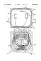
- FIGS. 1 and 2A currently available packaged optical amplifier assembly is shown schematically at FIGS. 1 and 2. It includes a number of commercially available optical components whose pigtails are spliced together to form the required optical circuit for the amplifier.
- FIG. 1shows, schematically, an assembled packaged optical amplifier 102.
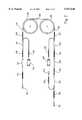
- FIG. 2shows the components of the package of FIG. 1 laid out as a key to show more clearly how the components are interconnected.
- the optical amplifier assembly 102is packaged in a housing comprising two interlocking metal compartments 104 and 106, the former holding passive optical components, the latter holding a printed circuit board (PCB) 108 on which are mounted optical components with electrical connections.
- PCBprinted circuit board
- the associated electronic components on the PCBare not shown. Fibre splices will be indicated by reference to the splice protectors which surround them.
- Optical signals to be amplified by the optical amplifier assembly 102are coupled to an input pigtail 110 by connecting to it a source optical fibre (not shown).
- the input pigtail 110is coupled to the input pigtail of an input isolator 112 by splice 114, the output pigtail of which is coupled to a first pigtail of an input dichroic wavelength division multiplexer (WDM) 116 by splice 118.
- WDMwavelength division multiplexer
- the output pigtail of a first laser diode optical pump 120is coupled to a second pigtail of the dichroic WDM 116 by a splice 122.
- the WDM 116outputs a combined input optical signal and optical pump signal at a third pigtail which is spliced to a first end 124 of a 30 m long erbium-doped, silica based fibre 126 by a splice 128.
- the amplifying fibre 126is wound on a pair of bobbins 130 and 132.
- a second end 134 of the amplifying fibre 126is coupled to a first pigtail of an output dichroic WDM 136 by a splice 138.
- the output pigtail of a second laser diode optical pump 138is coupled to a second pigtail of the output WDM 136 by a splice 139.
- the output WDM 136outputs the optical pump signal to the second end 134 of the amplifying fibre 126 whilst outputting an amplified optical signal received from the second end 134 of the amplifying fibre 126 to an output optical isolator 140, the pigtails of the output WDM 136 and output isolator 140 being coupled by a splice 142.
- the output pigtail of the output isolator 140is coupled to the input pigtail of an optical fibre coupler 144 by a splice 146.
- One output pigtail of the coupler 144is coupled to the input pigtail of a monitor diode 148 by a splice 150, a second output pigtail of the coupler 144 being coupled to an output pigtail 152 of the packaged amplifier 102 by a splice 154.
- the optical pump 120co-pumps the amplifying fibre 126 whilst the optical pump 138 counter-pumps the amplifying fibre 126.
- the requirement to couple the input isolator to the input WDMproduces a circle of fibre about 66 mm in diameter which together with the length of the optical devices and the splice protectors places a constraint on the package dimensions in the plane of the circle of the fibres.
- the need to couple the devices via their prepackaged pigtail input and output fibresmeans the optical signals undergo many transitions between guided and non-guided (free) propagation at collimating lenses within the packaged optical components.
- Each optical isolatorhas two, and each WDM at least two and sometimes three, collimators, arranged at each of their inputs and outputs. There is also a need to splice the various pigtails together which is a labour intensive operation.
- the present inventionseeks to provide a more compact packaged optical amplifier assembly. Accordingly there is provided a packaged optical amplifier assembly for amplifying an optical signal the assembly having an input, an output, an optical amplifying fibre having ends coupled to the input and output, respectively, and an optical pump coupled to one of the ends of the fibre, the optical signal being collimated and arranged to propagate unguided between said one of the ends and whichever of the input and the output is coupled to said one of the ends, and optical pump light from the optical pump being collimated and arranged to propagate unguided between the optical pump and the end of the fibre to which it is coupled and in which the optical pump light and optical signal are combined by a dichroic mirror.
- the provision of such optical coupling of the input, output, and pump sources to the appropriate first and second ends of the fibreeliminates the requirement for fibre guiding between the components thus reducing the number of collimating lenses compared to an equivalent prior art assembly and consequently the number of guided to unguided transitions.
- the only curved fibre componentis the amplifying optical fibre which can be bent to a circle of diameter in the order of 30 mm, compared to about 60 mm for a common transmission fibre, thus allowing the dimensions of the package to be greatly reduced.
- a single optical pumpit can be coupled to the first or to the second end of the optical amplifying fibre. It is not unusual however, to input pump power at both ends of the amplifying fibre.
- Each optical pumpis preferably located to minimise the angle of reflection of the pump signal by the dichroic mirror and the angle the mirror presents to the optical signal propagating through the mirror to minimise polarisation effects on reflection and transmission, for example by locating them adjacent to the end of the fibre to which it is optically coupled.
- the optical pump lightmay be reflected from an auxiliary mirror before being combined with the optical signal by the dichroic mirror.
- the use of such an auxiliary mirrormakes it easier to align the pump light with the optical signal.
- each pump laseris contained within an hermetically sealed sub-package within the optical amplifier assembly package.
- the dichroic mirror coupling the optical pump to the amplifying fibremay form an optical window in this hermetically sealed sub-package.
- each pump laseris contained within a separate hermetically sealed sub-package within the optical amplifier assembly package with the lenses which collimate the optical pump light forming optical windows in the sub-packages.
- optical isolatorsAt the input and output of the optical amplifier assembly as described above with reference to FIGS. 1 and 2. It has been found to be beneficial to mount such isolators with the optical pumps on a common thermoelectric cooling means to reduce the temperature dependency of the isolators' performance.
- a novel optical isolatorwhich may be used in other applications but which is particularly suitable for use with the optical amplifier assembly of the present invention comprises a housing having a through-hole, and a 45° Faraday rotator comprising a disc of magneto-optically active material located within the through-hole by a pair of annular permanent magnets, one on either side of the disc.
- Such an isolatoris particularly compact and easy to assemble and by operating on non-guided optical signals can be simply interposed in the apparatus of the present invention between the input and the first end of the fibre, and the second end of the fibre and the output, without the need for additional collimating lenses. It is to be noted that such an isolator could be employed in optical apparatus other than the optical amplifier apparatus of the present invention. Its use is optional, but preferred, with the amplifier assembly of the present invention.
- FIG. 1is a schematic diagram of a prior art packaged optical fibre amplifier assembly
- FIG. 2is a schematic diagram showing the interconnections of the optical components of the assembly of FIG. 1;
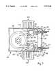
- FIG. 3is a schematic sectional plan view of a packaged optical fibre amplifier assembly in accordance with the present invention.
- FIG. 4is a schematic sectional plan view of a packaged optical fibre amplifier assembly in accordance with an alternative embodiment of the present invention.
- FIG. 5is schematic sectional view of an optical isolator suitable for use with the optical fibre amplifier assembly of either FIG. 3 or FIG. 4;
- FIG. 6is a schematic end view of the optical isolator of FIG. 5 viewed in the direction V--V in FIG. 5.
- a packaged optical amplifier assembly 302is housed in a metal housing 304.
- the lid of the housingis not shown.
- An optical signal to be amplifiedis coupled to an input 306 via a pigtail optical fibre 308 which is hermetically sealed with glass solder (not shown) within a metal feedthrough 310 which has a tubular portion 312 passing through a circular aperture 314 in the housing 304.
- the feedthrough 310has an annular flange 316 of radius greater than the aperture 314 an outer raised rim 317 which is projection welded to the housing 304 once the feedthrough 310 has been aligned within the aperture 314.
- a tubular collar 318initially a sliding fit on the outside of the tubular portion 312 of the feedthrough 310, supports within it a collimating lens 320 at the end of the collar 318 distant from the feedthrough 310.
- the collar 318is adjusted longitudinally on the feedthrough 310 until positioned to accurately collimate light exiting the fibre 308 whereupon it is fixed in position on the feedthrough 310.
- Collimated light from the collimating lens 320propagates through an optical isolator 322 (which will be described in detail later) to an optical multiplexer 324.
- the optical multiplexer 324comprises a sub-carrier 326 with a dichroic mirror 328 (a multilayer, high pass filter) which transmits light of a frequency to be amplified by an erbium-doped amplifying optical fibre 330 a first end 332 of which extends into, and is attached to, the sub-carrier 326.
- Erbium-doped fibreis obtainable from Lycom A/S, NKT Alle 75, DK-2605, Br.o slashed.ndby, Denmark and Fibrecore Ltd., York House, School Lane, Chandlers Ford, Hampshire S05 3DG, England, for example.
- a lens 334couples light propagating from the collimating lens 320 into the amplifying fibre 330.
- a 1480 nm diode laser 336which may be mounted in an hermetically sealed sub-package. Suitable lasers are manufactured by Hewlett-Packard Ltd., Whitehouse Road, Ipswich, Suffolk IP1 5PB, England and Lasertron, 37 North Avenue, Burlington, Mass. 01803, USA, for example.
- the laser 325is the optical pump for the amplifying fibre 330 in this exemplary embodiment of the present invention.
- the optical pump power from the laser 336is collimated by a lens 338 (which may be sealed in the same sub-package as the laser 336) and reflected by the dichroic mirror to the lens 334 associated with the first end 332 of the amplifying fibre 330 and so is coupled into the fibre 330.
- a pump monitor diode 339is used to monitor the optical output of the laser diode 336 in known manner.
- An optical signalpropagates along the fibre 330 to a second end 340 which mounted on a sub-carrier 342 which is the mirror image (along the axis of the fibre end 340) to sub-carrier 326 and whose components have been accorded the same reference numerals as the corresponding components of sub-carrier 326.
- the optical pump power from the laser 336 of the sub-carrier 342is coupled to the second end 340 of the fibre 330 via the dichroic mirror 328.
- the optical signalexits the second end 340 of the fibre 330, is collimated by lens 334 and is transmitted through the dichroic mirror 328 via an optical isolator 344 to an output 346 of the amplifying assembly 302.
- the optical isolator 344 and output 346are the same as the optical isolator 322 and input 306.
- the lens 320 of the output 346couples the optical signal from the second end 340 of the fibre 330 to an output fibre 348 sealed within a feedthrough 350 which is exactly the same as feedthrough 306 and aligned and fixed to the housing 304 in the same manner.
- the amplifying fibre 330is a 20 m long silica based erbium doped optical fibre, wound on a 15 mm radius bobbin 352.
- the sub-carriers 326 and 342 and optical isolators 322 and 344are all mounted on a common thermoelectric cooler 354 to provide relatively temperature insensitive operation to the performance of the amplifying assembly 302.
- the various electrical inputs and outputs to and from the laser diodes 336, monitor diodes 339 and thermoelectric cooler 354are provided at sets of electrical leads 356 and 358.
- the leads 356 and 358are sealed to the housing 304 by glass solder seals in known manner.
- the housing 302is of a metal whose thermal expansion matches that of the glass solder, for example Kovar (trademark).
- FIG. 4shows an assembly 502 which corresponds substantially to the assembly 302 of FIG. 3. Components which are common to both the assemblies of FIGS. 3 and 4 will not be describe again. However the assembly 502 has sub-carriers 526 and 542 which differ from the corresponding sub-assemblies in FIG. 3, and these sub-carriers will be described below.
- Each sub-assemblyhas a dichroic mirror 528 mounted in the light path between a collimating lens 320 and a lens 534 at each end of the fibre.
- a laser 536is mounted in the sub-assembly and has its output directed to a mirror 560.
- the mirrors 528 and 560are angled to reflect the light from the laser 536 so that it is aligned with the light passing between the collimating lens 320 and the lens 534. Both these mirrors are adjustable to enable this alignment to be achieved.
- the alignment requiredis that of parallelness and colinearity. This requires adjustment of four degrees of freedom; movement in two orthogonal planes to produce parallelness and movement about two orthogonal axes to produce colinearity. This adjustment can be achieved with the arrangement of FIG. 3, but it may require adjustment of the position of the laser 336 itself. In order to ensure good thermal conduction between the laser and the cooler 354, the laser should be permanently fixed to the cooler. The use of the auxiliary mirror 560 of FIG. 4 allows the laser to be permanently fixed in position and the alignment to be achieved by moving the mirrors 528 and 560.
- the isolators 322 and 344are identical and will now be described with reference to FIGS. 5 and 6.
- An isolator housing 458has a circular through-hole 460 including an annular ridge 462 protruding into the through-hole 460 at its mid point.
- a 400 nm thick plate, here in the form of a disc, of rare-earth iron garnet 466 of the same thickness as the ridge 462 and whose outer radius is the same as the inner radius of the ridge 462is held in position by a pair of annular ferromagnets 468, one each side of the disc 460, whose outer radii equal the radius of the through-hole 460 and whose inner radii are smaller than the radius of the disc 460.
- the ferromagnets 468have outer surfaces flush with outer portions 470 of the housing 458 so they can be retained by the planar surfaces of birefringent, tapered plates 472 of rutile or calcite, for example.
- the plates 472are laterally located on the surfaces to housing 458 by shoulders 474 against which one end of each plate 472 abuts.
- the plates 472are glued to the housing 458 to form the completed optical isolator 332 or 342 of FIG. 3.
- the disc 466 and ferromagnets 468are dimensioned and designed to form a 45° Faraday rotator in known manner.
- the tapered birefringent platesconstitute polarisers which provide polarisation independent optical isolation in the manner described in detail in U.S. Pat. No. 4,548,478.
- Other polarising meansmay be employed for example polarising sheets such as 200 nm Polacor (trademark) sheet.
- the various optical surfaces of the optical componentsare provided with antireflection coatings in known manner.
Landscapes
- Physics & Mathematics (AREA)
- Engineering & Computer Science (AREA)
- Electromagnetism (AREA)
- Optics & Photonics (AREA)
- Nonlinear Science (AREA)
- Plasma & Fusion (AREA)
- Power Engineering (AREA)
- General Physics & Mathematics (AREA)
- Microelectronics & Electronic Packaging (AREA)
- Optical Couplings Of Light Guides (AREA)
- Lasers (AREA)
Abstract
Description
Claims (12)
Applications Claiming Priority (3)
| Application Number | Priority Date | Filing Date | Title |
|---|---|---|---|
| GB9412528 | 1994-06-22 | ||
| GB9412528AGB9412528D0 (en) | 1994-06-22 | 1994-06-22 | Packaged optical amplifier assembly |
| PCT/GB1995/001407WO1995035590A1 (en) | 1994-06-22 | 1995-06-16 | Packaged optical amplifier assembly |
Publications (1)
| Publication Number | Publication Date |
|---|---|
| US5917648Atrue US5917648A (en) | 1999-06-29 |
Family
ID=10757142
Family Applications (1)
| Application Number | Title | Priority Date | Filing Date |
|---|---|---|---|
| US08/750,671Expired - LifetimeUS5917648A (en) | 1994-06-22 | 1995-06-16 | Packaged optical amplifier assembly |
Country Status (5)
| Country | Link |
|---|---|
| US (1) | US5917648A (en) |
| EP (1) | EP0766878B1 (en) |
| DE (1) | DE69530202T2 (en) |
| GB (1) | GB9412528D0 (en) |
| WO (1) | WO1995035590A1 (en) |
Cited By (58)
| Publication number | Priority date | Publication date | Assignee | Title |
|---|---|---|---|---|
| US6132104A (en)* | 1998-12-02 | 2000-10-17 | Corning Incorporated | Detachable plug-in pump card assembly |
| US6201637B1 (en)* | 1998-08-04 | 2001-03-13 | Samsung Electronics Co., Ltd. | Long-wavelength optical fiber amplifier |
| US6266180B1 (en)* | 1998-07-09 | 2001-07-24 | Fujitsu Limited | Optical fiber amplifier using optical fiber having a portion which suppresses nonlinear optical phenomena |
| WO2001061402A1 (en)* | 2000-02-16 | 2001-08-23 | Adc Telecommunications, Inc. | Fiber optic isolator for use with multiple-wavelength optical signals |
| US6320694B1 (en)* | 1997-10-17 | 2001-11-20 | Fujitsu Limited | Optical amplifier for use in optical communications equipment |
| US6334020B1 (en)* | 1999-09-30 | 2001-12-25 | The Boeing Company | Compact package structure for fiber optic devices |
| US6335823B2 (en) | 1997-10-17 | 2002-01-01 | Fujitsu Limited | Optical amplifier for use in optical communications equipment |
| WO2001076022A3 (en)* | 2000-04-03 | 2002-03-07 | Corona Optical Systems Inc | Optical amplifier |
| US6507430B2 (en) | 2001-02-23 | 2003-01-14 | Photon X, Inc. | Long wavelength optical amplifier |
| US6556340B1 (en)* | 2001-04-06 | 2003-04-29 | Onetta, Inc. | Optical amplifiers and upgrade modules |
| US6567578B1 (en) | 2000-02-16 | 2003-05-20 | Adc Telecommunications | Fiber optic device operating at two or more wavelengths |
| US20030123141A1 (en)* | 2001-11-19 | 2003-07-03 | Aydin Yeniay | L band optical amplifier |
| FR2837290A1 (en)* | 2002-03-15 | 2003-09-19 | Alcatel Optronics France | Ultra-compact optical amplifier used in telecommunications comprises housing containing an optical pump, a light amplification and guiding unit, passive optical coupling elements, and light guides |
| US20030185486A1 (en)* | 2002-03-27 | 2003-10-02 | Bennett Kevin W. | Optical amplification module |
| WO2002101431A3 (en)* | 2001-06-08 | 2003-12-18 | Photon X Inc | Compact optical amplifier module |
| US6717720B2 (en)* | 2001-06-06 | 2004-04-06 | Keopsys, Inc. | Hermetic pump module for double cladding fiber amplifiers and method for making same |
| US6731426B2 (en) | 2001-02-23 | 2004-05-04 | Photon-X, Inc. | Long wavelength optical amplifier |
| US6781748B2 (en) | 2001-09-28 | 2004-08-24 | Photon-X, Llc | Long wavelength optical amplifier |
| US6788870B1 (en) | 2001-11-08 | 2004-09-07 | Tyco Telecommunications (Us) Inc. | Isothermal fiber optic tray |
| US6806998B2 (en)* | 2002-03-20 | 2004-10-19 | Adc Telecommunications, Inc. | Raman amplifier with high power distribution bypass |
| EP1388746A3 (en)* | 2002-06-13 | 2004-12-15 | Agilent Technologies, Inc. | Optical packaging assembly and method of making the same |
| US20050213921A1 (en)* | 2004-03-08 | 2005-09-29 | Mertesdorf Daniel R | Fiber access terminal |
| US20060093303A1 (en)* | 2004-11-03 | 2006-05-04 | Randy Reagan | Fiber drop terminal |
| US20060153516A1 (en)* | 2005-01-13 | 2006-07-13 | Napiorkowski John J | Network interface device having integral slack storage compartment |
| US20070031093A1 (en)* | 2005-07-01 | 2007-02-08 | Toshio Takagi | Optical module with lens holder projection-welded to butterfly package |
| US20070237484A1 (en)* | 2006-04-05 | 2007-10-11 | Randy Reagan | Universal bracket for mounting a drop terminal |
| US20080037945A1 (en)* | 2006-08-09 | 2008-02-14 | Jeff Gniadek | Cable payout systems and methods |
| US7333708B2 (en) | 2004-01-27 | 2008-02-19 | Corning Cable Systems Llc | Multi-port optical connection terminal |
| USRE40358E1 (en) | 1998-07-27 | 2008-06-03 | Adc Telecommunications, Inc. | Outside plant fiber distribution apparatus and method |
| US20080232743A1 (en)* | 2007-03-23 | 2008-09-25 | Erik Gronvall | Drop terminal with anchor block for retaining a stub cable |
| US20090046985A1 (en)* | 2007-08-16 | 2009-02-19 | Erik Gronvall | Fiber Optic Enclosure Internal Cable Management |
| US20090067037A1 (en)* | 2007-09-10 | 2009-03-12 | Yokogawa Electric Corporation | Optical amplification apparatus and optical communication apparatus |
| US20090123115A1 (en)* | 2007-10-09 | 2009-05-14 | Erik Gronvall | Drop Terminal Releasable Engagement Mechanism |
| US7558458B2 (en) | 2007-03-08 | 2009-07-07 | Adc Telecommunications, Inc. | Universal bracket for mounting a drop terminal |
| US20090226138A1 (en)* | 2005-11-28 | 2009-09-10 | Amphotonix Limited | Fibre-Optic Module |
| US7680388B2 (en) | 2004-11-03 | 2010-03-16 | Adc Telecommunications, Inc. | Methods for configuring and testing fiber drop terminals |
| US20100103489A1 (en)* | 2008-10-27 | 2010-04-29 | Ondax, Inc. | Optical pulse shaping method and apparatus |
| US7740409B2 (en) | 2007-09-19 | 2010-06-22 | Corning Cable Systems Llc | Multi-port optical connection terminal |
| US7844158B2 (en) | 2007-10-09 | 2010-11-30 | Adc Telecommunications, Inc. | Mini drop terminal |
| US7986407B2 (en) | 2008-08-04 | 2011-07-26 | Ondax, Inc. | Method and apparatus using volume holographic wavelength blockers |
| US20110216316A1 (en)* | 2008-05-15 | 2011-09-08 | Ondax, Inc. | Measurement of volume holographic gratings |
| US20130034328A1 (en)* | 2010-02-10 | 2013-02-07 | Oclaro Technology Limited | Reduced length optoelectronic devices |
| US8755663B2 (en) | 2010-10-28 | 2014-06-17 | Corning Cable Systems Llc | Impact resistant fiber optic enclosures and related methods |
| US8873926B2 (en) | 2012-04-26 | 2014-10-28 | Corning Cable Systems Llc | Fiber optic enclosures employing clamping assemblies for strain relief of cables, and related assemblies and methods |
| US9069151B2 (en) | 2011-10-26 | 2015-06-30 | Corning Cable Systems Llc | Composite cable breakout assembly |
| US9130340B1 (en)* | 2010-03-01 | 2015-09-08 | Polar Laser Laboratories, Llc | System and method for output port management in short-length fiber amplifiers |
| US20150270676A1 (en)* | 2014-03-19 | 2015-09-24 | Xtera Communications, Inc. | Multi-span optical communications link having remote optically pumped amplifier |
| US9587983B1 (en) | 2015-09-21 | 2017-03-07 | Ondax, Inc. | Thermally compensated optical probe |
| US9599565B1 (en) | 2013-10-02 | 2017-03-21 | Ondax, Inc. | Identification and analysis of materials and molecular structures |
| CN107681424A (en)* | 2016-08-01 | 2018-02-09 | 南京理工大学 | A kind of compact high power single mode fiber laser for monitoring power output |
| CN109256661A (en)* | 2017-07-13 | 2019-01-22 | Ii-Vi有限公司 | A kind of compact optical fiber amplifier |
| US10749309B2 (en)* | 2015-03-19 | 2020-08-18 | Ii-Vi Incorporated | Compact optical fiber amplifier |
| JP2022000909A (en)* | 2016-03-18 | 2022-01-04 | 浜松ホトニクス株式会社 | Laser oscillator and laser processing device |
| US11226458B2 (en)* | 2017-08-29 | 2022-01-18 | Nec Corporation | Pluggable optical module and optical communication system |
| US11314025B2 (en)* | 2020-01-20 | 2022-04-26 | Sumitomo Electric Industries, Ltd. | Optical transceiver |
| US11454771B2 (en)* | 2020-01-30 | 2022-09-27 | Sumitomo Electric Industries, Ltd. | Optical transceiver |
| CN118169937A (en)* | 2024-01-23 | 2024-06-11 | 珠海映讯芯光科技有限公司 | Semiconductor optical amplifier |
| JP2024109787A (en)* | 2020-07-24 | 2024-08-14 | ウーシー タックリンク オプトエレクトロニクス テクノロジー カンパニー リミテッド | SFP+ package compatible optical fiber amplifier |
Families Citing this family (5)
| Publication number | Priority date | Publication date | Assignee | Title |
|---|---|---|---|---|
| DE19517952A1 (en)* | 1995-05-16 | 1996-11-21 | Ams Optotech Vertrieb Gmbh | Optical amplifier with praseodymium-doped optical fiber |
| US5703990A (en)* | 1996-03-14 | 1997-12-30 | Lucent Technologies Inc. | Apparatus for housing a linearized optical fiber amplifier |
| IT1283721B1 (en)* | 1996-04-05 | 1998-04-30 | Pirelli Cavi S P A Ora Pirelli | APPARATUS AND METHOD FOR HOUSING OPTICAL COMPONENTS |
| IT1283720B1 (en)* | 1996-04-05 | 1998-04-30 | Pirelli Cavi S P A Ora Pirelli | EQUIPMENT AND METHOD FOR THE HOUSING OF ELECTRO-OPTICAL COMPONENTS WITH HIGH HEAT EMISSION |
| JP2004186609A (en)* | 2002-12-06 | 2004-07-02 | Central Glass Co Ltd | Optical-fiber amplifier module |
Citations (13)
| Publication number | Priority date | Publication date | Assignee | Title |
|---|---|---|---|---|
| GB2138585A (en)* | 1980-10-17 | 1984-10-24 | Raytheon Co | Faraday rotator |
| US4804256A (en)* | 1988-01-11 | 1989-02-14 | Wilson Donald K | Faraday rotators using a movable optical element |
| JPH01194200A (en)* | 1988-01-29 | 1989-08-04 | Sony Corp | Memory device |
| EP0372448A1 (en)* | 1988-12-09 | 1990-06-13 | Alcatel Cit | Optical module with an integrated isolator for coupling a semiconductor laser to a light guide |
| EP0409258A2 (en)* | 1989-07-20 | 1991-01-23 | Sumitomo Electric Industries, Ltd. | A fiber optical amplifier |
| EP0444694A2 (en)* | 1990-03-02 | 1991-09-04 | Fujitsu Limited | Optical coupler |
| US5105307A (en)* | 1988-11-04 | 1992-04-14 | Fuji Electrochemical Co., Ltd. | Optical isolator |
| EP0508149A2 (en)* | 1991-04-08 | 1992-10-14 | General Instrument Corporation Of Delaware | Low noise high power optical fiber amplifier |
| FR2678075A1 (en)* | 1991-06-21 | 1992-12-24 | Hitachi Ltd | Optical isolator, optical circuit and amplifier using optical fibre doped with a rare earth |
| EP0520199A1 (en)* | 1991-05-28 | 1992-12-30 | Mitsubishi Gas Chemical Company, Inc. | Optical isolator |
| EP0563524A1 (en)* | 1992-03-19 | 1993-10-06 | Alcatel SEL Aktiengesellschaft | Optical transmission system with optical fibre amplifiers and control of the emitter wavelength |
| EP0586713A1 (en)* | 1992-03-26 | 1994-03-16 | Nippon Petrochemicals Co., Ltd. | Polymeric optical fiber amplifier |
| JPH1194200A (en) | 1997-07-29 | 1999-04-09 | Elf Antar Fr | Pipeline provided with some longitudinal ducts |
Family Cites Families (1)
| Publication number | Priority date | Publication date | Assignee | Title |
|---|---|---|---|---|
| JP2753539B2 (en)* | 1989-07-28 | 1998-05-20 | 日本電信電話株式会社 | Optical fiber amplifier |
- 1994
- 1994-06-22GBGB9412528Apatent/GB9412528D0/enactivePending
- 1995
- 1995-06-16USUS08/750,671patent/US5917648A/ennot_activeExpired - Lifetime
- 1995-06-16WOPCT/GB1995/001407patent/WO1995035590A1/enactiveIP Right Grant
- 1995-06-16EPEP95920174Apatent/EP0766878B1/ennot_activeExpired - Lifetime
- 1995-06-16DEDE69530202Tpatent/DE69530202T2/ennot_activeExpired - Lifetime
Patent Citations (14)
| Publication number | Priority date | Publication date | Assignee | Title |
|---|---|---|---|---|
| GB2138585A (en)* | 1980-10-17 | 1984-10-24 | Raytheon Co | Faraday rotator |
| US4804256A (en)* | 1988-01-11 | 1989-02-14 | Wilson Donald K | Faraday rotators using a movable optical element |
| JPH01194200A (en)* | 1988-01-29 | 1989-08-04 | Sony Corp | Memory device |
| US5105307A (en)* | 1988-11-04 | 1992-04-14 | Fuji Electrochemical Co., Ltd. | Optical isolator |
| EP0372448A1 (en)* | 1988-12-09 | 1990-06-13 | Alcatel Cit | Optical module with an integrated isolator for coupling a semiconductor laser to a light guide |
| US5121451A (en)* | 1988-12-09 | 1992-06-09 | Alcatel Cit | Optical head with an integrated isolator for coupling a semiconductor laser to a light guide |
| EP0409258A2 (en)* | 1989-07-20 | 1991-01-23 | Sumitomo Electric Industries, Ltd. | A fiber optical amplifier |
| EP0444694A2 (en)* | 1990-03-02 | 1991-09-04 | Fujitsu Limited | Optical coupler |
| EP0508149A2 (en)* | 1991-04-08 | 1992-10-14 | General Instrument Corporation Of Delaware | Low noise high power optical fiber amplifier |
| EP0520199A1 (en)* | 1991-05-28 | 1992-12-30 | Mitsubishi Gas Chemical Company, Inc. | Optical isolator |
| FR2678075A1 (en)* | 1991-06-21 | 1992-12-24 | Hitachi Ltd | Optical isolator, optical circuit and amplifier using optical fibre doped with a rare earth |
| EP0563524A1 (en)* | 1992-03-19 | 1993-10-06 | Alcatel SEL Aktiengesellschaft | Optical transmission system with optical fibre amplifiers and control of the emitter wavelength |
| EP0586713A1 (en)* | 1992-03-26 | 1994-03-16 | Nippon Petrochemicals Co., Ltd. | Polymeric optical fiber amplifier |
| JPH1194200A (en) | 1997-07-29 | 1999-04-09 | Elf Antar Fr | Pipeline provided with some longitudinal ducts |
Non-Patent Citations (6)
| Title |
|---|
| Article entitled In Line (Pigtailed) Polarization Independent Optical Isolator by W.L. Emkey et al., Optical Fiber Communication Conference, 1989 Technical Digest Series, vol. 5, Conference Edition, Feb. 6 9, 1989, p.14g.* |
| Article entitled In-Line (Pigtailed) Polarization-Independent Optical Isolator by W.L. Emkey et al., Optical Fiber Communication Conference, 1989 Technical Digest Series, vol. 5, Conference Edition, Feb. 6-9, 1989, p.14g. |
| Delavaux et al, IEEE Photonics Technology Letters, 6, 1994 Mar, 3, pp. 376 379.* |
| Delavaux et al, IEEE Photonics Technology Letters, 6, 1994-Mar, #3, pp. 376-379. |
| Nakagawa et al, Jour. of Lightwave Tech., vol. 9, #2, Feb. 1991, pp. 198-208. |
| Nakagawa et al, Jour. of Lightwave Tech., vol. 9, 2, Feb. 1991, pp. 198 208.* |
Cited By (111)
| Publication number | Priority date | Publication date | Assignee | Title |
|---|---|---|---|---|
| US6320694B1 (en)* | 1997-10-17 | 2001-11-20 | Fujitsu Limited | Optical amplifier for use in optical communications equipment |
| US6335823B2 (en) | 1997-10-17 | 2002-01-01 | Fujitsu Limited | Optical amplifier for use in optical communications equipment |
| US6373623B1 (en) | 1997-10-17 | 2002-04-16 | Fujitsu Limited | Optical amplifier for use in optical communications equipment |
| US6266180B1 (en)* | 1998-07-09 | 2001-07-24 | Fujitsu Limited | Optical fiber amplifier using optical fiber having a portion which suppresses nonlinear optical phenomena |
| USRE40358E1 (en) | 1998-07-27 | 2008-06-03 | Adc Telecommunications, Inc. | Outside plant fiber distribution apparatus and method |
| USRE41777E1 (en) | 1998-07-27 | 2010-09-28 | Adc Telecommunications, Inc. | Outside plant fiber distribution apparatus and method |
| USRE42258E1 (en) | 1998-07-27 | 2011-03-29 | Adc Telecommunications, Inc. | Outside plant fiber distribution apparatus and method |
| US6201637B1 (en)* | 1998-08-04 | 2001-03-13 | Samsung Electronics Co., Ltd. | Long-wavelength optical fiber amplifier |
| US6132104A (en)* | 1998-12-02 | 2000-10-17 | Corning Incorporated | Detachable plug-in pump card assembly |
| US6334020B1 (en)* | 1999-09-30 | 2001-12-25 | The Boeing Company | Compact package structure for fiber optic devices |
| US6532321B1 (en) | 2000-02-16 | 2003-03-11 | Adc Telecommunications, Inc. | Fiber optic isolator for use with multiple-wavelength optical signals |
| US6567578B1 (en) | 2000-02-16 | 2003-05-20 | Adc Telecommunications | Fiber optic device operating at two or more wavelengths |
| WO2001061402A1 (en)* | 2000-02-16 | 2001-08-23 | Adc Telecommunications, Inc. | Fiber optic isolator for use with multiple-wavelength optical signals |
| US6760160B2 (en) | 2000-02-16 | 2004-07-06 | Adc Telecommunications, Inc. | Fiber optic isolator for use with multiple-wavelength optical signals |
| WO2001076022A3 (en)* | 2000-04-03 | 2002-03-07 | Corona Optical Systems Inc | Optical amplifier |
| US6507430B2 (en) | 2001-02-23 | 2003-01-14 | Photon X, Inc. | Long wavelength optical amplifier |
| US6731426B2 (en) | 2001-02-23 | 2004-05-04 | Photon-X, Inc. | Long wavelength optical amplifier |
| US6556340B1 (en)* | 2001-04-06 | 2003-04-29 | Onetta, Inc. | Optical amplifiers and upgrade modules |
| US6717720B2 (en)* | 2001-06-06 | 2004-04-06 | Keopsys, Inc. | Hermetic pump module for double cladding fiber amplifiers and method for making same |
| WO2002101431A3 (en)* | 2001-06-08 | 2003-12-18 | Photon X Inc | Compact optical amplifier module |
| US6781748B2 (en) | 2001-09-28 | 2004-08-24 | Photon-X, Llc | Long wavelength optical amplifier |
| US6788870B1 (en) | 2001-11-08 | 2004-09-07 | Tyco Telecommunications (Us) Inc. | Isothermal fiber optic tray |
| US20030123141A1 (en)* | 2001-11-19 | 2003-07-03 | Aydin Yeniay | L band optical amplifier |
| FR2837290A1 (en)* | 2002-03-15 | 2003-09-19 | Alcatel Optronics France | Ultra-compact optical amplifier used in telecommunications comprises housing containing an optical pump, a light amplification and guiding unit, passive optical coupling elements, and light guides |
| US6806998B2 (en)* | 2002-03-20 | 2004-10-19 | Adc Telecommunications, Inc. | Raman amplifier with high power distribution bypass |
| US6917731B2 (en)* | 2002-03-27 | 2005-07-12 | Corning Incorporated | Optical amplification module |
| US20030185486A1 (en)* | 2002-03-27 | 2003-10-02 | Bennett Kevin W. | Optical amplification module |
| EP1388746A3 (en)* | 2002-06-13 | 2004-12-15 | Agilent Technologies, Inc. | Optical packaging assembly and method of making the same |
| US7653282B2 (en) | 2004-01-27 | 2010-01-26 | Corning Cable Systems Llc | Multi-port optical connection terminal |
| US7333708B2 (en) | 2004-01-27 | 2008-02-19 | Corning Cable Systems Llc | Multi-port optical connection terminal |
| US20070140642A1 (en)* | 2004-03-08 | 2007-06-21 | Adc Telecommunications, Inc. | Fiber access terminal |
| US8363999B2 (en) | 2004-03-08 | 2013-01-29 | Adc Telecommunications, Inc. | Fiber access terminal |
| US20050213921A1 (en)* | 2004-03-08 | 2005-09-29 | Mertesdorf Daniel R | Fiber access terminal |
| US7539387B2 (en) | 2004-03-08 | 2009-05-26 | Adc Telecommunications, Inc. | Fiber access terminal |
| US7539388B2 (en) | 2004-03-08 | 2009-05-26 | Adc Telecommunications, Inc. | Fiber access terminal |
| US20090297112A1 (en)* | 2004-03-08 | 2009-12-03 | Adc Telecommunications, Inc. | Fiber access terminal |
| US20080131068A1 (en)* | 2004-03-08 | 2008-06-05 | Adc Telecommunications, Inc. | Fiber Access Terminal |
| US7397997B2 (en) | 2004-03-08 | 2008-07-08 | Adc Telecommunications, Inc. | Fiber access terminal |
| US7400815B2 (en) | 2004-03-08 | 2008-07-15 | Adc Telecommunications, Inc. | Fiber access terminal |
| US20080226252A1 (en)* | 2004-03-08 | 2008-09-18 | Adc Telecommunications, Inc. | Fiber Access Terminal |
| US7941027B2 (en) | 2004-03-08 | 2011-05-10 | Adc Telecommunications, Inc. | Fiber access terminal |
| US20080260345A1 (en)* | 2004-03-08 | 2008-10-23 | Adc Telecommunications, Inc. | Fiber access terminal |
| US20080260344A1 (en)* | 2004-03-08 | 2008-10-23 | Adc Telecommunications, Inc. | Fiber access terminal |
| US7292763B2 (en) | 2004-03-08 | 2007-11-06 | Adc Telecommunications, Inc. | Fiber access terminal |
| US7480437B2 (en) | 2004-03-08 | 2009-01-20 | Adc Telecommunications, Inc. | Fiber access terminal |
| USRE43762E1 (en) | 2004-03-08 | 2012-10-23 | Adc Telecommunications, Inc. | Fiber access terminal |
| US7489849B2 (en) | 2004-11-03 | 2009-02-10 | Adc Telecommunications, Inc. | Fiber drop terminal |
| US9851522B2 (en) | 2004-11-03 | 2017-12-26 | Commscope Technologies Llc | Fiber drop terminal |
| US12204157B2 (en) | 2004-11-03 | 2025-01-21 | Commscope Technologies Llc | Fiber drop terminal |
| US7805044B2 (en) | 2004-11-03 | 2010-09-28 | Adc Telecommunications, Inc. | Fiber drop terminal |
| US11567278B2 (en) | 2004-11-03 | 2023-01-31 | Commscope Technologies Llc | Fiber drop terminal |
| US10042136B2 (en) | 2004-11-03 | 2018-08-07 | Commscope Technologies Llc | Fiber drop terminal |
| US20090148120A1 (en)* | 2004-11-03 | 2009-06-11 | Adc Telecommunications, Inc. | Fiber drop terminal |
| US20060093303A1 (en)* | 2004-11-03 | 2006-05-04 | Randy Reagan | Fiber drop terminal |
| US7680388B2 (en) | 2004-11-03 | 2010-03-16 | Adc Telecommunications, Inc. | Methods for configuring and testing fiber drop terminals |
| US10890729B2 (en) | 2004-11-03 | 2021-01-12 | Commscope Technologies Llc | Fiber drop terminal and bracket |
| US7627222B2 (en) | 2004-11-03 | 2009-12-01 | Adc Telecommunications, Inc. | Fiber drop terminal |
| US20060153516A1 (en)* | 2005-01-13 | 2006-07-13 | Napiorkowski John J | Network interface device having integral slack storage compartment |
| US20070031093A1 (en)* | 2005-07-01 | 2007-02-08 | Toshio Takagi | Optical module with lens holder projection-welded to butterfly package |
| US7325985B2 (en)* | 2005-07-01 | 2008-02-05 | Sumitomo Electric Industries, Ltd. | Optical module with lens holder projection-welded to butterfly package |
| US20090226138A1 (en)* | 2005-11-28 | 2009-09-10 | Amphotonix Limited | Fibre-Optic Module |
| US20110123166A1 (en)* | 2006-04-05 | 2011-05-26 | Adc Telecommunications, Inc. | Universal bracket for mounting a drop terminal |
| US8218935B2 (en) | 2006-04-05 | 2012-07-10 | Adc Telecommunications, Inc. | Universal bracket for mounting a drop terminal |
| US7477824B2 (en) | 2006-04-05 | 2009-01-13 | Adc Telecommunications, Inc. | Universal bracket for mounting a drop terminal |
| US7844160B2 (en) | 2006-04-05 | 2010-11-30 | Adc Telecommunications, Inc. | Universal bracket for mounting a drop terminal |
| US20070237484A1 (en)* | 2006-04-05 | 2007-10-11 | Randy Reagan | Universal bracket for mounting a drop terminal |
| US20080037945A1 (en)* | 2006-08-09 | 2008-02-14 | Jeff Gniadek | Cable payout systems and methods |
| US7599598B2 (en) | 2006-08-09 | 2009-10-06 | Adc Telecommunications, Inc. | Cable payout systems and methods |
| US8121456B2 (en) | 2006-08-09 | 2012-02-21 | Adc Telecommunications, Inc. | Cable payout systems and methods |
| US7558458B2 (en) | 2007-03-08 | 2009-07-07 | Adc Telecommunications, Inc. | Universal bracket for mounting a drop terminal |
| US7512304B2 (en) | 2007-03-23 | 2009-03-31 | Adc Telecommunications, Inc. | Drop terminal with anchor block for retaining a stub cable |
| US20080232743A1 (en)* | 2007-03-23 | 2008-09-25 | Erik Gronvall | Drop terminal with anchor block for retaining a stub cable |
| US20090046985A1 (en)* | 2007-08-16 | 2009-02-19 | Erik Gronvall | Fiber Optic Enclosure Internal Cable Management |
| US20090067037A1 (en)* | 2007-09-10 | 2009-03-12 | Yokogawa Electric Corporation | Optical amplification apparatus and optical communication apparatus |
| US7740409B2 (en) | 2007-09-19 | 2010-06-22 | Corning Cable Systems Llc | Multi-port optical connection terminal |
| US20110067452A1 (en)* | 2007-10-09 | 2011-03-24 | Adc Telecommunications, Inc. | Mini drop terminal |
| US7903923B2 (en) | 2007-10-09 | 2011-03-08 | Adc Telecommunications, Inc. | Drop terminal releasable engagement mechanism |
| US7844158B2 (en) | 2007-10-09 | 2010-11-30 | Adc Telecommunications, Inc. | Mini drop terminal |
| US20090123115A1 (en)* | 2007-10-09 | 2009-05-14 | Erik Gronvall | Drop Terminal Releasable Engagement Mechanism |
| US8213761B2 (en) | 2007-10-09 | 2012-07-03 | Adc Telecommunications | Mini drop terminal |
| US8049885B1 (en) | 2008-05-15 | 2011-11-01 | Ondax, Inc. | Method and apparatus for large spectral coverage measurement of volume holographic gratings |
| US8139212B2 (en) | 2008-05-15 | 2012-03-20 | Ondax, Inc. | Measurement of volume holographic gratings |
| US20110216316A1 (en)* | 2008-05-15 | 2011-09-08 | Ondax, Inc. | Measurement of volume holographic gratings |
| US8184285B2 (en) | 2008-08-04 | 2012-05-22 | Ondax, Inc. | Method and apparatus using volume holographic wavelength blockers |
| US7986407B2 (en) | 2008-08-04 | 2011-07-26 | Ondax, Inc. | Method and apparatus using volume holographic wavelength blockers |
| US8369017B2 (en) | 2008-10-27 | 2013-02-05 | Ondax, Inc. | Optical pulse shaping method and apparatus |
| US20110216384A1 (en)* | 2008-10-27 | 2011-09-08 | Ondax, Inc. | Correcting spatial beam deformation |
| US9097896B2 (en) | 2008-10-27 | 2015-08-04 | Ondax, Inc. | Correcting spatial beam deformation |
| US20100103489A1 (en)* | 2008-10-27 | 2010-04-29 | Ondax, Inc. | Optical pulse shaping method and apparatus |
| US20130034328A1 (en)* | 2010-02-10 | 2013-02-07 | Oclaro Technology Limited | Reduced length optoelectronic devices |
| US9488784B2 (en)* | 2010-02-10 | 2016-11-08 | Oclaro Technology Limited | Reduced length optoelectronic devices |
| US9130340B1 (en)* | 2010-03-01 | 2015-09-08 | Polar Laser Laboratories, Llc | System and method for output port management in short-length fiber amplifiers |
| US8755663B2 (en) | 2010-10-28 | 2014-06-17 | Corning Cable Systems Llc | Impact resistant fiber optic enclosures and related methods |
| US9069151B2 (en) | 2011-10-26 | 2015-06-30 | Corning Cable Systems Llc | Composite cable breakout assembly |
| US8873926B2 (en) | 2012-04-26 | 2014-10-28 | Corning Cable Systems Llc | Fiber optic enclosures employing clamping assemblies for strain relief of cables, and related assemblies and methods |
| US9599565B1 (en) | 2013-10-02 | 2017-03-21 | Ondax, Inc. | Identification and analysis of materials and molecular structures |
| US10502688B2 (en) | 2013-10-02 | 2019-12-10 | Ondax, Inc. | Identification and analysis of materials and molecular structures |
| US9735532B2 (en)* | 2014-03-19 | 2017-08-15 | Neptune Subsea Ip Limited | Multi-span optical communications link having remote optically pumped amplifier |
| CN106464381A (en)* | 2014-03-19 | 2017-02-22 | 埃克斯特拉通信公司 | Multi-span optical communications link having remote optically pumped amplifier |
| US20150270676A1 (en)* | 2014-03-19 | 2015-09-24 | Xtera Communications, Inc. | Multi-span optical communications link having remote optically pumped amplifier |
| CN106464381B (en)* | 2014-03-19 | 2019-08-13 | 海王星海底Ip有限公司 | Multi sectional optical communication link with remote optical pumping formula amplifier |
| US10749309B2 (en)* | 2015-03-19 | 2020-08-18 | Ii-Vi Incorporated | Compact optical fiber amplifier |
| US9587983B1 (en) | 2015-09-21 | 2017-03-07 | Ondax, Inc. | Thermally compensated optical probe |
| JP2022000909A (en)* | 2016-03-18 | 2022-01-04 | 浜松ホトニクス株式会社 | Laser oscillator and laser processing device |
| CN107681424A (en)* | 2016-08-01 | 2018-02-09 | 南京理工大学 | A kind of compact high power single mode fiber laser for monitoring power output |
| CN109256661A (en)* | 2017-07-13 | 2019-01-22 | Ii-Vi有限公司 | A kind of compact optical fiber amplifier |
| US11226458B2 (en)* | 2017-08-29 | 2022-01-18 | Nec Corporation | Pluggable optical module and optical communication system |
| US11314025B2 (en)* | 2020-01-20 | 2022-04-26 | Sumitomo Electric Industries, Ltd. | Optical transceiver |
| US11454771B2 (en)* | 2020-01-30 | 2022-09-27 | Sumitomo Electric Industries, Ltd. | Optical transceiver |
| JP2024109787A (en)* | 2020-07-24 | 2024-08-14 | ウーシー タックリンク オプトエレクトロニクス テクノロジー カンパニー リミテッド | SFP+ package compatible optical fiber amplifier |
| CN118169937A (en)* | 2024-01-23 | 2024-06-11 | 珠海映讯芯光科技有限公司 | Semiconductor optical amplifier |
Also Published As
| Publication number | Publication date |
|---|---|
| EP0766878A1 (en) | 1997-04-09 |
| DE69530202D1 (en) | 2003-05-08 |
| DE69530202T2 (en) | 2003-12-11 |
| GB9412528D0 (en) | 1994-08-10 |
| WO1995035590A1 (en) | 1995-12-28 |
| EP0766878B1 (en) | 2003-04-02 |
Similar Documents
| Publication | Publication Date | Title |
|---|---|---|
| US5917648A (en) | Packaged optical amplifier assembly | |
| US7031574B2 (en) | Plug-in module for providing bi-directional data transmission | |
| US5692082A (en) | Laser diode module and depolarizer | |
| US7039278B1 (en) | Single-fiber bi-directional transceiver | |
| US6842467B1 (en) | Fiber optic laser transmitter with reduced near end reflections | |
| JP2000091677A (en) | Optical amplifier and optical amplification fiber module | |
| US7050694B2 (en) | Continuously variable attenuation of an optical signal using an optical isolator | |
| US7251394B2 (en) | Optical isolator with tilted optical isolator element | |
| US7043101B1 (en) | Integrated optical pump module | |
| JPS6170516A (en) | Semiconductor laser module with optical isolator | |
| JPH06181352A (en) | Light amplifier optical module | |
| JP2005134803A (en) | Ferrule with optical isolator and optical transmission/reception module equipped with the same | |
| CA2133556A1 (en) | Improvements to optical phase shifting | |
| JP4956004B2 (en) | Optical isolator | |
| JP4794056B2 (en) | Optical device | |
| JPH07301763A (en) | Optical coupler and optical fiber amplifier | |
| US6624938B1 (en) | Optical circulator | |
| CN115981069B (en) | All-fiber entanglement source based on PPKTP crystal and its device coupling packaging method | |
| JP2004198549A (en) | Optical isolator, optical module, and optical amplifier | |
| JPH0667118A (en) | Optical coupler | |
| JPH0764021A (en) | Optical coupler and optical fiber amplifier | |
| JPS62150210A (en) | Semiconductor laser/optical fiber coupling module with optical isolator | |
| JP3590226B2 (en) | Optical module | |
| WO2004104664A1 (en) | Polarization device | |
| JPH05316052A (en) | Polarization diversity optical receiver |
Legal Events
| Date | Code | Title | Description |
|---|---|---|---|
| AS | Assignment | Owner name:HEWLETT-PACKARD COMPANY, CALIFORNIA Free format text:ASSIGNMENT OF ASSIGNORS INTEREST;ASSIGNOR:HEWLETT-PACKARD LIMITED;REEL/FRAME:009543/0216 Effective date:19981015 | |
| STCF | Information on status: patent grant | Free format text:PATENTED CASE | |
| AS | Assignment | Owner name:HEWLETT-PACKARD COMPANY, COLORADO Free format text:MERGER;ASSIGNOR:HEWLETT-PACKARD COMPANY;REEL/FRAME:010759/0049 Effective date:19980520 | |
| AS | Assignment | Owner name:AGILENT TECHNOLOGIES INC, CALIFORNIA Free format text:ASSIGNMENT OF ASSIGNORS INTEREST;ASSIGNOR:HEWLETT-PACKARD COMPANY;REEL/FRAME:010977/0540 Effective date:19991101 | |
| FPAY | Fee payment | Year of fee payment:4 | |
| AS | Assignment | Owner name:AVAGO TECHNOLOGIES GENERAL IP PTE. LTD., SINGAPORE Free format text:ASSIGNMENT OF ASSIGNORS INTEREST;ASSIGNOR:AGILENT TECHNOLOGIES, INC.;REEL/FRAME:017207/0020 Effective date:20051201 | |
| AS | Assignment | Owner name:AVAGO TECHNOLOGIES FIBER IP (SINGAPORE) PTE. LTD., Free format text:ASSIGNMENT OF ASSIGNORS INTEREST;ASSIGNOR:AVAGO TECHNOLOGIES GENERAL IP (SINGAPORE) PTE. LTD.;REEL/FRAME:017675/0294 Effective date:20051201 | |
| FPAY | Fee payment | Year of fee payment:8 | |
| FPAY | Fee payment | Year of fee payment:12 | |
| AS | Assignment | Owner name:AVAGO TECHNOLOGIES GENERAL IP (SINGAPORE) PTE. LTD Free format text:MERGER;ASSIGNOR:AVAGO TECHNOLOGIES FIBER IP (SINGAPORE) PTE. LTD.;REEL/FRAME:030369/0672 Effective date:20121030 | |
| AS | Assignment | Owner name:AVAGO TECHNOLOGIES GENERAL IP (SINGAPORE) PTE. LTD Free format text:CORRECTIVE ASSIGNMENT TO CORRECT THE NAME OF THE ASSIGNEE PREVIOUSLY RECORDED ON REEL 017207 FRAME 0020. ASSIGNOR(S) HEREBY CONFIRMS THE ASSIGNMENT;ASSIGNOR:AGILENT TECHNOLOGIES, INC.;REEL/FRAME:038633/0001 Effective date:20051201 |