US5916525A - Closure vessel assembly - Google Patents
Closure vessel assemblyDownload PDFInfo
- Publication number
- US5916525A US5916525AUS07/984,762US98476292AUS5916525AUS 5916525 AUS5916525 AUS 5916525AUS 98476292 AUS98476292 AUS 98476292AUS 5916525 AUS5916525 AUS 5916525A
- Authority
- US
- United States
- Prior art keywords
- vessel
- closure
- sealing
- lip
- wall
- Prior art date
- Legal status (The legal status is an assumption and is not a legal conclusion. Google has not performed a legal analysis and makes no representation as to the accuracy of the status listed.)
- Expired - Fee Related
Links
- 238000007789sealingMethods0.000claimsabstractdescription160
- 239000000463materialSubstances0.000claimsabstractdescription19
- 239000004033plasticSubstances0.000claimsabstractdescription11
- 229920003023plasticPolymers0.000claimsabstractdescription11
- 239000012530fluidSubstances0.000claimsdescription12
- 229920000098polyolefinPolymers0.000claimsdescription4
- 230000001154acute effectEffects0.000claimsdescription2
- 230000001419dependent effectEffects0.000claims1
- 229920002313fluoropolymerPolymers0.000claims1
- 239000004811fluoropolymerSubstances0.000claims1
- 230000009471actionEffects0.000description5
- 238000004519manufacturing processMethods0.000description5
- 239000000523sampleSubstances0.000description5
- 238000011109contaminationMethods0.000description4
- -1polypropylenePolymers0.000description3
- IJGRMHOSHXDMSA-UHFFFAOYSA-NAtomic nitrogenChemical compoundN#NIJGRMHOSHXDMSA-UHFFFAOYSA-N0.000description2
- 230000008901benefitEffects0.000description2
- 239000002826coolantSubstances0.000description2
- 230000006735deficitEffects0.000description2
- 230000006870functionEffects0.000description2
- 239000007788liquidSubstances0.000description2
- 238000000034methodMethods0.000description2
- 230000009467reductionEffects0.000description2
- XLYOFNOQVPJJNP-UHFFFAOYSA-NwaterSubstancesOXLYOFNOQVPJJNP-UHFFFAOYSA-N0.000description2
- 239000004698PolyethyleneSubstances0.000description1
- 239000004743PolypropyleneSubstances0.000description1
- 239000000654additiveSubstances0.000description1
- 238000004925denaturationMethods0.000description1
- 230000036425denaturationEffects0.000description1
- 238000006073displacement reactionMethods0.000description1
- 230000000694effectsEffects0.000description1
- 230000002708enhancing effectEffects0.000description1
- 230000007613environmental effectEffects0.000description1
- 230000002349favourable effectEffects0.000description1
- 239000008233hard waterSubstances0.000description1
- 238000003780insertionMethods0.000description1
- 230000037431insertionEffects0.000description1
- 229910052757nitrogenInorganic materials0.000description1
- 229920000573polyethylenePolymers0.000description1
- 229920001155polypropylenePolymers0.000description1
- 229920001343polytetrafluoroethylenePolymers0.000description1
- 230000004044responseEffects0.000description1
- 239000000126substanceSubstances0.000description1
Images


Classifications
- B—PERFORMING OPERATIONS; TRANSPORTING
- B65—CONVEYING; PACKING; STORING; HANDLING THIN OR FILAMENTARY MATERIAL
- B65D—CONTAINERS FOR STORAGE OR TRANSPORT OF ARTICLES OR MATERIALS, e.g. BAGS, BARRELS, BOTTLES, BOXES, CANS, CARTONS, CRATES, DRUMS, JARS, TANKS, HOPPERS, FORWARDING CONTAINERS; ACCESSORIES, CLOSURES, OR FITTINGS THEREFOR; PACKAGING ELEMENTS; PACKAGES
- B65D41/00—Caps, e.g. crown caps or crown seals, i.e. members having parts arranged for engagement with the external periphery of a neck or wall defining a pouring opening or discharge aperture; Protective cap-like covers for closure members, e.g. decorative covers of metal foil or paper
- B65D41/02—Caps or cap-like covers without lines of weakness, tearing strips, tags, or like opening or removal devices
- B65D41/04—Threaded or like caps or cap-like covers secured by rotation
- B65D41/0407—Threaded or like caps or cap-like covers secured by rotation with integral sealing means
- B65D41/0414—Threaded or like caps or cap-like covers secured by rotation with integral sealing means formed by a plug, collar, flange, rib or the like contacting the internal surface of a container neck
Definitions
- the present inventionrelates to a closure vessel assembly as well as to a closure and a vessel for such an assembly.
- the present inventionrelates to vessels for use in laboratory work at extreme temperatures, which vessels have fluid volumes in the order of up to a few milliliters.
- Conventional vesselsgenerally are vessels of the screw-threaded closure vessel type and are provided with separate sealing elements such as an O-ring.
- Such a vessel structuremay result in contamination of the contents of the vessel when the material of the O-rings has been damaged by aggressive fluids contents.
- the additional sealing elementcauses specific production costs.
- the closureis provided with a sealing lip having a shape of an extended parabola in a longitudinal cross-section.
- the sealing lipis provided with a lip sealing surface which is resiliently and sealingly urged against an internal rim of the mouth of the vessel when the closure is in screw-threaded engagement with the vessel.
- a housing face wall and a housing side wallabruptly merge into each other, i.e. the radius of curvature of the internal rim approximates zero in a longitudinal cross-section.
- the lip sealing surfaceis subjected to an annular line contact resulting in substantial surface pressures. Such surface pressures cause the lip seal to be deflected inwardly for a substantial amount when the closure is in screw-threaded engagement with the vessel.
- Such sealing structureis not very critical at room temperature. If, however, the vessel is used in a wide range of temperatures of e.g. -136° C. to +100° C., the closure vessel assembly will experience critical conditions during the required closure time. In particular at high temperatures there will be a substantial deformation of the material of the sealing means resulting in a reduction of the sealing forces along with a corresponding leakage of the fluid contents of the vessel. This situation is aggravated by the increase of vapor pressure of the probes at the higher temperatures which may attain 100° C. when the vessel is immersed in a hard water bath. Low temperatures such as -196° C. which are encountered when using liquid nitrogen as a cooling medium result in a plastic deformation of the plastic vessel in particular in the prestressed sealing area. As a result the cooling medium may leak into the vessel and may evaporate causing rupturing of the closure. This may result in environmental contamination.
- the present inventionprovides a closure vessel assembly, in particular for use in laboratory work within a wide range of temperatures, the assembly comprising a vessel and a closure of plastics material, said vessel having a wall and an upper mouth and said closure having a top wall, said vessel and said closure being provided with locking means effective therebetween and sealing means for providing a fluid tight seal therebetween, said sealing means including an annular sealing lip depending from the closure top wall and extending into said vessel mouth, said sealing lip having a sealing surface in sealing engagement with a sealing surface on said vessel wall, said lip sealing surface and said vessel sealing surface in a longitudinal cross-section having radii of curvature such as to provide for minimum surface pressure yet sufficient sealing between said sealing surfaces despite any deformation of the materials of said sealing surfaces during the required closing time of the vessel.
- the present inventionprovides a closure vessel assembly, in particular for use in laboratory work within a wide range of temperatures, the assembly comprising a vessel and a closure of plastic materials, said vessel having a wall and an upper mouth and said closure having a top wall, said vessel and said closure being provided with locking means effective therebetween and sealing means for providing a fluid tight seal therebetween, said sealing means including an annular sealing lip depending from the closure top wall and extending into said vessel mouth, said sealing lip having a sealing surface in sealing engagement with a sealing surface on said vessel wall, said sealing lip comprising an extension enhancing engagement between said lip sealing surface and said vessel sealing surface due to superatmospheric pressure within the vessel so as to improve the sealing action therebetween.
- a small surface pressure at the sealing surfaces as provided by the present inventionmay be sufficient to provide a fluid tight seal within the desired temperature range and, on the other hand results in such a small plastic deformation of the materials during the desired closure time that the sealing function is not detrimentally affected but provides for a sufficient minimum sealing tightness.
- This approachis materially different from that of the prior art sealing techniques which had been based on the assumption that a high surface pressure is necessary for providing a fluid tight seal.
- a small surface pressureis obtained by appropriate selection of the radii of curvature of the lip sealing surface and vessel sealing surface as seen in a longitudinal cross-section of the closure and vessel assembly.
- the minimum surface pressureis obtained by having both infinite radii of curvature, i.e. the lip sealing surface and the vessel sealing surface are having line contact with each other as seen in a longitudinal cross-section.
- a sealing structuremight cause problems, in particular manufacturing tolerances in the manufacture of the sealing surfaces and/or damage to the sealing surfaces may result in loss of sealing quality.
- only one of the radii of curvature of the lip and vessel sealing surfacesis selected to be infinite.
- the other of the radii of curvature of the lip and vessel sealing surfaceis of a smaller value which is still sufficiently greater than zero.
- Such a combination of radii of curvature of the lip and vessel sealing surfaceallows to obtain small surface pressures and to compensate for inaccuracies in the dimensions of the sealing surfaces and/or damage to the sealing surfaces, in particular to the sealing surface having the smaller radius of curvature.
- the smaller radius of curvatureis provided at the vessel sealing surface which is more likely to be damaged.
- a radius of 1 mm for the sealing surface of a vessel having a volume of, e.g., 1.3 mlmay be considered as being “substantially greater than zero", and a smaller radius of curvature of about 1 mm has shown to provide for excellent results.
- the stiffness of the sealing lipis chosen so that the sealing lip when under surface pressure is subjected only to a small resilient deformation which nevertheless is sufficient to obtain a desired sealing force and to compensate for manufacturing or other errors. This will further reduce the speed of deformation of the sealing lip in the respective load situations.
- the desired stiffness of the sealing lipis preferably obtained by the shape and dimensions thereof and the type of material used.
- the sealing lipmay be designed so that it will be of a compact shape, for example by having its height not exceed the width of its base.
- a truncated shape of the sealing lip cross-sectionmay have a favorable influence on its deformation behavior.
- an acute angle of inclination of the lip sealing surface from the closure top surface towards the longitudinal axis of the vesselwill provide for an improved error compensation and an increase of the adjustment range for the surface pressures due to a radial deformation of the sealing lip.
- the length of the sealing lipis selected so that its lip sealing surface is urged against the vessel sealing surface due to an overpressure within the vessel as caused by the vapor pressure of the fluid probe within the vessel.
- the resulting plastic deformation of the materials under the actual temperature conditionsis being used to enhance or at least maintain the sealing which originally was effected by a resilient biasing of the sealing lip.
- the sealingis obtained substantially independently of any locking forces between the closure and the vessel; this is particularly true if the sealing lip is urged against the vessel sealing surface in a radial direction.
- the sealing lip surface and the vessel sealing surfaceare provided adjacent the free end of the sealing lip.
- the vessel sealing surfaceis provided at a portion of the vessel wall of reduced cross-section.
- an arrangement wherein the sealing lip surface extends substantially parallel to the longitudinal axis of the vesselis preferred.
- the closure top surfaceis preferably of a stiffness so as to prevent or reduce any deflections thereof due to pressure forces in order to prevent any disengagement of the lip sealing surface from the vessel sealing surface.
- the closure top surfacepreferably is of a substantial wall thickness.
- said vessel wallis surrounded by an annular member closely adjacent to said vessel sealing surface without any space therebetween.
- said locking meanscomprise locking elements at an internal side of a closure side wall and on an external side of said vessel wall. Accordingly, the locking elements are not in contact with the contents of the vessel.
- the locking elementscomprise helical threads. This allows for a precise adjustment of the surface pressures. If the locking elements comprise snap-on elements for a presnapping action, the snapping function is simplified and yet fine adjustment of the surface pressures is still possible.
- said threadscomprise multiple threads on each of said vessel wall and said closure sidewall and one of said multiple threads on each of said vessel wall and said closure side wall comprises an initial portion of reduced height extending along a fraction of a turn of the respective thread so as to serve as snap-on elements adapted to be brought into snapping engagement with each other.
- the initial portion of the threads close to the vessel mouthare used for the pre-snapping action and the other portions of the threads are used for the locking action.
- said sealing lipextends beyond said closure side wall in a longitudinal direction of said vessel which will facilitate to introduce the sealing lip into the vessel mouth.
- the vesselmay be made from a polyolefin such as polypropylene or polyethylene. Also combinations of various polyolefins for the closure and the vessel may be used. Furthermore fluorpolymers such as polytetrafluorethylene may be used in particular in connection with the handling of very aggressive substances. With a view of an increased stiffness of the sealing lip and closure top wall it might be preferable to provide that the closure has a modulus of elasticity in excess of that of the vessel. This may be obtained by the selection of appropriate plastics or their composition e.g. by using specific additives.
- the present inventionprovides for the required sealing under the desired conditions without the use of separate sealing elements such as O-rings and without the respective manufacturing and mounting expenditure. Furthermore, the present invention overcomes the contamination problems of the prior art.
- the vessel according to the present inventionis used in particular as a safety vessel (centrifuging) as a vessel for storing and/or transporting fluid probes, as a cryo-vessel and as a vessel for denaturation of albumen in a water bath of 100° C.
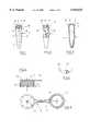
- FIG. 1is a side elevation of a vessel having a vessel sealing surface on an internal rim of the vessel mouth;
- FIG. 2a side elevation of the vessel shown in FIG. 1 which, however, has been rotated about 90°;
- FIG. 3is a longitudinal cross-section of the vessel shown in FIG. 1 and 2;
- FIG. 4is a partial longitudinal cross-section of a closure for the above vessel in an enlarged scale
- FIG. 5is a top view of the closure shown in FIG. 4;
- FIG. 6is a view of the detail as indicated by the dash dotted circle VI in FIG. 3 in an enlarged scale;
- FIG. 7a diagramatic partial cross-section to show the cooperation between the vessel and closure of FIG. 1 to 6 when under pressure
- FIG. 8a view corresponding to FIG. 7 showing a modified closure having a closure top wall of increased stiffness
- FIG. 9a view corresponding to FIG. 8 of a somewhat modified version of the closure and vessel
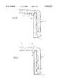
- FIG. 10is a longitudinal cross-section of a closure having a sealing lip of increased length in accordance with a second aspect of the present invention.
- FIG. 11is a longitudinal cross-section of a closure vessel assembly including a closure according to FIG. 10;
- FIG. 12is a view similar to FIG. 11 showing a deformation on the closure vessel assembly
- FIG. 13a view similar to FIG. 12 showing a deformation of the closure vessel assembly after an extended period of time.
- FIG. 1 to 3show a vessel 1 of a closure vessel assembly in accordance with the present invention.
- the vessel 1which is of a volume of 1.3 ml includes a tapered bottom portion 2 and a cylindrical main portion 3.
- the vessel 1includes, in the area of portions 2 and 3, a vessel wall 4 having level indicating marks 5.
- the vessel at its upper endincludes a threaded portion 6 comprising a pair of threads 7.
- the initial portions 8,8" of the pair of threads of the threaded portion 6are offset with respect to each other about 90°.
- initial portions 9,9" of the threadsare of a reduced height over a quarter of the threaded portion 6. It is only the following thread sections 10,10" that have a distinct saw tooth profile over a half circumference of the threaded portion 6.
- Closure 11includes a top wall portion 12 merging at its outer periphery into a cylindrical closure wall 13. Closure wall 13 is provided with a pair of internal threads 14 having a continuous saw tooth profile from the beginning to the end of the threads.
- the closure 11is arranged to have the initial areas of its two threads to be snapped on the initial sections 9,9" of the threads 7 of the vessel 1; thereafter the closure 11 may be rotated to be brought into full threaded engagement with the saw tooth profile thread portions 10,10" to fully interlock the closure with the vessel.
- the closureBefore the closure 11 is interlocked with the vessel 1, the closure may be connected to the vessel 1 by means of a flexible flap 15 integrally connected to one side of the closure; to this end a flap eyelet 16 having an extension area 17 is engaged into an external groove 18 of vessel 1. Below the groove 18 the vessel 1 is provided with an integral annular member 19 which serves an abutment both for the flap eyelet 16 and the threaded portion of the closure.
- the interlocking engagement between the closure 11 and the vessel 1also provides a sealing action between these components.
- the respective sealing meanscomprises, as shown in FIG. 4, an annular sealing lip 20 depending from the closure top wall 12, concentric to the longitudinal axis of the closure and being of truncated shape in a longitudinal cross-section.
- the outer flanks of the truncated sealing lip 20comprise lip sealing surfaces 21 which are inclined to the longitudinal axis of the closure 11 about an angle of 25°.
- the radius of curvature of the lip sealing surface 21, when viewed in a longitudinal cross-section,is infinite, so that the lip sealing surface 21 is practically a straight line.
- the sealing lip 20cooperates with a vessel sealing surface 23 provided on an internal rim of a vessel mouth 24 as shown in FIG. 3 and 6.
- the vessel sealing surface 23has a radius of curvature of 1 mm as seen in a longitudinal cross-section.
- closure vessel assemblyis shown by dash dotted lines in a condition when the closure 11 has been removed and before there is any superatmospheric pressure within the vessel due to a temperature rise, and the closure vessel assembly is shown in straight lines in a condition when an overpressure has been built up within the vessel after a closure time of about 20 minutes.
- the closure top wall 12has been deformed outwardly due to flow of material in response to pressure forces, resulting in a slight displacement of the lip sealing surface 21 and the vessel sealing surface 23. Nevertheless, the sealing effectiveness is still acceptable because the selected radii of curvature of the sealing surfaces 21 and 23 result in low surface pressures and in an only slight deformation of the used materials which is assisted by slightly prestressing the sealing lip 20. Furthermore, an annular member 25 which is integral with the closure side wall 13 and which supports the vessel wall 4 close to the vessel mouth 24 from the outside, additionally counteracts any deformation in the area of the sealing means.
- the closure 11has been modified to have a top wall 12 of increased thickness reducing any deflections due to an internal pressure within the closure vessel assembly, thus reducing any impairment of the sealing effectiveness between the lip sealing surface 21 and the vessel sealing surface 23.
- impairment of the sealing effectivenessis still relatively substantial because a material having a modulus of elasticity of 250 N/mm 2 has been used for the closure 11 and a material having a modulus of elasticity of 500 N/mm 2 has been used for the vessel 1.
- the moduli of elasticity of the materials of the vessel and closurehave been reversed, i.e. the modulus for the closure 11 is 500 n/mm 2 and the modulus for the vessel 1 is 250 N/mm 2 .
- the modulus for the closure 11is 500 n/mm 2
- the modulus for the vessel 1is 250 N/mm 2 .
- FIG. 10shows another embodiment of a closure vessel assembly including a closure 26 having internal threads 27 and a connection flap 28 adapted to cooperate with a threaded portion 6 and a groove 18 of the embodiment shown in FIG. 1 to 3.
- a sealing lip 30 depending from the closure top wall 29is provided which extends beyond the closure side wall in parallel to the longitudinal axis of the closure.
- the sealing lip 30is provided with an external cylindrical lip sealing surface 31 having a small radius 32 at the free end of the sealing lip so as to facilitate insertion of the sealing lip into a vessel mouth.
- FIG. 11shows an associated vessel 33 having at its upper end a threaded portion 34 with threads 35 similar to those shown in FIG. 1 to 3. Threads 35 of vessel 33 are interlocked with threads 27 of the closure 26, the closure flap 28 having its eyelet 34 secured in a groove 35' of the vessel 33.
- a wall 36 of the vessel 33is provided, at a location spaced from a vessel mouth 37, with a chamfer 38 so that the wall 36 has a reduced cross-section in this area.
- the chamfer 38is followed by a sealing surface 39 comprised of a cylindrical inner surface of the vessel wall 36.
- the vessel wall 36is slightly recessed.
- the sealing lip 30 of the closure 26is shown, by dash dotted lines, in its original condition when it has not been deformed. However, it is to be noted that the sealing lip 30 when it is inserted into the vessel mouth 37 is resilently deflected inwards as soon as its radius 32 and the lip sealing surface engage the chamfer 38 and thereafter the vessel sealing surface 39.
- FIG. 12 and 13show the closure vessel assembly in a condition where the sealing lip 30 has been deflected inwardly; the initial deflection or deformation has been indicated by dotted lines and the deflection or deformation after a certain closure time has been indicated by full lines.
- the sealing lips 30At the time of the initial deformation the sealing lips 30 have only their lip sealing surface 31 engage the vessel wall 36 in the area of the vessel sealing surface 39. Even though there is no internal pressurization of the vessel at this time, the resilient biasing of the sealing lip 30 provides for a surface pressure between the sealing surfaces 31 and 39 which is sufficient to ensure a fluid tight seal.
- a gap 40 between the sealing lip 30 and the vessel wall 36extends from the sealing surface 31,39 to the vessel mouth 37 so as to provide a space into which the sealing lip may be deformed.
- FIG. 12shows, additionally to the initial deformations, the deformation after about one minute
- FIG. 13shows additionally to the initial deformation, the final deformation after about one hour. It should be appreciated that the deformation speed is rapidly reduced to small values, and approximately constant sealing conditions will be reached.
- the deformation behaviour as indicated in FIG. 7 to 9 and FIG. 12, 13has been calculated by using the FEM (Finite Elements Method), with the calculations having been based on the characteristics of a polyolefin.
- the closure vessel assembly in accordance with the present inventionallows to obtain a loss rate of less than 0.3% (i.e. less than 3.9 mg loss of liquid) with a probe volume of 1.3 ml in a water bath at 100° C. and for a closure time of at least 30 minutes.
Landscapes
- Engineering & Computer Science (AREA)
- Mechanical Engineering (AREA)
- Closures For Containers (AREA)
- Sampling And Sample Adjustment (AREA)
- Devices For Use In Laboratory Experiments (AREA)
Abstract
Description
Claims (7)
Applications Claiming Priority (2)
| Application Number | Priority Date | Filing Date | Title |
|---|---|---|---|
| DE4139810 | 1991-12-03 | ||
| DE4139810ADE4139810C2 (en) | 1991-12-03 | 1991-12-03 | Lid jar |
Publications (1)
| Publication Number | Publication Date |
|---|---|
| US5916525Atrue US5916525A (en) | 1999-06-29 |
Family
ID=6446151
Family Applications (1)
| Application Number | Title | Priority Date | Filing Date |
|---|---|---|---|
| US07/984,762Expired - Fee RelatedUS5916525A (en) | 1991-12-03 | 1992-12-03 | Closure vessel assembly |
Country Status (6)
| Country | Link |
|---|---|
| US (1) | US5916525A (en) |
| EP (1) | EP0545297B1 (en) |
| JP (1) | JP2802357B2 (en) |
| AT (1) | ATE155102T1 (en) |
| DE (2) | DE4139810C2 (en) |
| ES (1) | ES2104801T3 (en) |
Cited By (12)
| Publication number | Priority date | Publication date | Assignee | Title |
|---|---|---|---|---|
| US20030178792A1 (en)* | 2002-03-25 | 2003-09-25 | Pridmore Ken T. | Sealing head |
| US20030203800A1 (en)* | 2002-04-26 | 2003-10-30 | Hitachi Koki Co., Ltd. | Culture tube and angle rotor receiving the tube in centrifuge |
| US6702134B2 (en) | 2001-09-28 | 2004-03-09 | Gen-Probe Incorporated | Closure system |
| US20110052459A1 (en)* | 2008-04-24 | 2011-03-03 | Toyo Seikan Kaisha Ltd | Compound container and pouring-out method |
| US8506804B1 (en) | 2004-05-10 | 2013-08-13 | Scientific Plastic Products, Inc. | Flash chromatography cartridge |
| US9279761B1 (en) | 2015-02-06 | 2016-03-08 | John L. Sternick | Cuvette system |
| US9297499B2 (en) | 2012-12-06 | 2016-03-29 | Cook Medical Technologies Llc | Cryogenic storage container, storage device, and methods of using the same |
| US9494510B2 (en) | 2015-02-06 | 2016-11-15 | John L. Sternick | Cuvette system |
| US9518898B2 (en) | 2012-12-06 | 2016-12-13 | Cook Medical Technologies Llc | Cryogenic storage container with sealing closure and methods of using the same |
| US20220009678A1 (en)* | 2020-07-08 | 2022-01-13 | Japeloco Pty Ltd. | Closures and vessels with closures |
| US20230271756A1 (en)* | 2020-07-08 | 2023-08-31 | Veraseal Pty Limited | Closures and vessels with closures |
| USD1008489S1 (en)* | 2021-03-17 | 2023-12-19 | Eppendorf Se | Lid for test tubes |
Families Citing this family (4)
| Publication number | Priority date | Publication date | Assignee | Title |
|---|---|---|---|---|
| DE19521924C2 (en)* | 1994-06-24 | 1999-08-05 | Lange Gmbh Dr Bruno | Screw cap for a vessel and device for automatically closing the vessel |
| DE9418060U1 (en)* | 1994-11-11 | 1996-03-14 | SC - Sanguis Counting Kontrollblutherstellungs- und Vertriebs GmbH, 51588 Nümbrecht | Sample tube and end cap, especially for capillary blood collection |
| DE20313316U1 (en) | 2003-08-28 | 2003-10-23 | KABE-Labortechnik GmbH, 51588 Nümbrecht | Stopper for a tube, containing a liquid sample for medical analysis, has an inserted cylindrical section with a membrane to prevent contamination when a portion is extracted by a needle |
| DE102021114819A1 (en) | 2021-06-09 | 2022-12-15 | Eppendorf Ag | screw-top jar |
Citations (18)
| Publication number | Priority date | Publication date | Assignee | Title |
|---|---|---|---|---|
| US3371808A (en)* | 1966-08-01 | 1968-03-05 | Evert D. Velt | Unitary safety cap |
| US3607098A (en)* | 1967-10-23 | 1971-09-21 | Carl Sloth Strande | Containers for laboratory use |
| US4202455A (en)* | 1977-11-16 | 1980-05-13 | Three Sisters Ranch Enterprises | Molded plastic container for use with a cap having inner and outer skirts |
| US4241188A (en)* | 1979-10-09 | 1980-12-23 | Becton, Dickinson And Company | Culture bottle having stopper lock |
| US4526756A (en)* | 1982-05-10 | 1985-07-02 | Evergreen Industries, Inc. | Device for interconnecting specimen collecting tubes |
| GB2166422A (en)* | 1984-11-05 | 1986-05-08 | Sunbeam Plastics Corp | Screw-threaded closure-container assembly |
| US4654127A (en)* | 1984-04-11 | 1987-03-31 | Sentech Medical Corporation | Self-calibrating single-use sensing device for clinical chemistry and method of use |
| US4713219A (en)* | 1984-01-24 | 1987-12-15 | Eppendorf Geratebau Netheler & Hinz Gmbh | Plastic reaction vessel |
| US4755356A (en)* | 1986-01-23 | 1988-07-05 | Robbins Scientific Corporation | Locking microcentrifuge tube |
| EP0279126A2 (en)* | 1987-02-10 | 1988-08-24 | Helena Laboratories Corporation | Specimen collection apparatus |
| US4896780A (en)* | 1988-05-09 | 1990-01-30 | Multi-Technology Inc. | Fail safe releasible locks for capped disposable centrifuge containers |
| EP0376435A1 (en)* | 1988-11-03 | 1990-07-04 | Nalge Company | Bottle closure |
| US4953741A (en)* | 1988-05-09 | 1990-09-04 | Multi-Technology Inc. | Medical fail safe releasible locks and/or seals for capped disposable centrifuge containers, cryogenic vials and the like |
| US4956103A (en)* | 1988-05-09 | 1990-09-11 | Multi-Technology Inc. | Fail safe releasible locks for capped disposable centrifuge containers |
| EP0439842A1 (en)* | 1990-01-29 | 1991-08-07 | Herbert Strassheimer | Plastic closure |
| US5128104A (en)* | 1987-04-27 | 1992-07-07 | Murphy Harold R | Cuvette for automated testing machine |
| US5145646A (en)* | 1991-06-03 | 1992-09-08 | Abbott Laboratories | Reagent bottle and cap |
| US5167929A (en)* | 1988-07-07 | 1992-12-01 | Walter Sarstedt Geraete Und Verbrauchsmaterial Fuer Medizin Und Wissenshaft | Reaction vessel for receiving minimal quantities of fluid samples |
Family Cites Families (16)
| Publication number | Priority date | Publication date | Assignee | Title |
|---|---|---|---|---|
| DE8112952U1 (en)* | 1981-09-10 | Heinrich Axmann KG Kunststoff Plastik-Werk, 5000 Köln | "Container with screw cap" | |
| BE534639A (en)* | ||||
| FR1153553A (en)* | 1956-05-28 | 1958-03-12 | I N G E Ind Naz Guarnizioni Er | Screw cap with hermetic seal without seal for all bottles |
| AT244787B (en)* | 1961-01-07 | 1966-01-25 | James W Wandell | Closing screw cap made of plastic |
| CH394845A (en)* | 1961-08-29 | 1965-06-30 | Proplasto Ag | Plastic bottle |
| DE1851126U (en)* | 1962-01-16 | 1962-05-03 | Schmalbach Ag J A | LOCKING DEVICE MADE OF ELASTIC MATERIAL. |
| FR1487412A (en)* | 1966-05-20 | 1967-07-07 | Thermosetting molded screw cap for squeeze bottles | |
| FR2109021B3 (en)* | 1970-10-30 | 1973-08-10 | Lille Inst Pasteur | |
| DE2204979A1 (en)* | 1972-02-03 | 1973-08-09 | Werner Nolte | SCREW CAP CLOSURE |
| CH580013A5 (en)* | 1974-11-05 | 1976-09-30 | Obrist Ag Albert | |
| AU1546676A (en)* | 1975-07-01 | 1978-01-05 | Gramp G & Sons Pty Ltd | Bottle closure means |
| CH649057A5 (en)* | 1982-06-10 | 1985-04-30 | Stericric Sa | BOTTLE FOR LIQUIDS CAPABLE OF SUPPORTING TERMINAL STERILIZATION, PROVIDED WITH A TAMPER-FREE CLOSING DEVICE. |
| US4712699A (en)* | 1986-10-02 | 1987-12-15 | Captive Plastics, Inc. | Package employing unique seal |
| US4753358A (en)* | 1987-03-02 | 1988-06-28 | Promega Corporation | Vial cap coupling device |
| FR2633903B1 (en)* | 1988-07-08 | 1990-10-12 | Bouchons Plastiques | SHUTTERING SYSTEM COMBINING A SCREW CAPSULE AND THE THREADED NUT OF A CONTAINER |
| DE9006079U1 (en)* | 1990-05-30 | 1990-09-13 | Bethkenhagen, Jürgen, 5223 Nümbrecht | Lid |
- 1991
- 1991-12-03DEDE4139810Apatent/DE4139810C2/ennot_activeExpired - Fee Related
- 1992
- 1992-11-27ATAT92120267Tpatent/ATE155102T1/ennot_activeIP Right Cessation
- 1992-11-27ESES92120267Tpatent/ES2104801T3/ennot_activeExpired - Lifetime
- 1992-11-27EPEP92120267Apatent/EP0545297B1/ennot_activeExpired - Lifetime
- 1992-11-27DEDE59208682Tpatent/DE59208682D1/ennot_activeExpired - Fee Related
- 1992-12-03JPJP4350628Apatent/JP2802357B2/ennot_activeExpired - Fee Related
- 1992-12-03USUS07/984,762patent/US5916525A/ennot_activeExpired - Fee Related
Patent Citations (18)
| Publication number | Priority date | Publication date | Assignee | Title |
|---|---|---|---|---|
| US3371808A (en)* | 1966-08-01 | 1968-03-05 | Evert D. Velt | Unitary safety cap |
| US3607098A (en)* | 1967-10-23 | 1971-09-21 | Carl Sloth Strande | Containers for laboratory use |
| US4202455A (en)* | 1977-11-16 | 1980-05-13 | Three Sisters Ranch Enterprises | Molded plastic container for use with a cap having inner and outer skirts |
| US4241188A (en)* | 1979-10-09 | 1980-12-23 | Becton, Dickinson And Company | Culture bottle having stopper lock |
| US4526756A (en)* | 1982-05-10 | 1985-07-02 | Evergreen Industries, Inc. | Device for interconnecting specimen collecting tubes |
| US4713219A (en)* | 1984-01-24 | 1987-12-15 | Eppendorf Geratebau Netheler & Hinz Gmbh | Plastic reaction vessel |
| US4654127A (en)* | 1984-04-11 | 1987-03-31 | Sentech Medical Corporation | Self-calibrating single-use sensing device for clinical chemistry and method of use |
| GB2166422A (en)* | 1984-11-05 | 1986-05-08 | Sunbeam Plastics Corp | Screw-threaded closure-container assembly |
| US4755356A (en)* | 1986-01-23 | 1988-07-05 | Robbins Scientific Corporation | Locking microcentrifuge tube |
| EP0279126A2 (en)* | 1987-02-10 | 1988-08-24 | Helena Laboratories Corporation | Specimen collection apparatus |
| US5128104A (en)* | 1987-04-27 | 1992-07-07 | Murphy Harold R | Cuvette for automated testing machine |
| US4896780A (en)* | 1988-05-09 | 1990-01-30 | Multi-Technology Inc. | Fail safe releasible locks for capped disposable centrifuge containers |
| US4953741A (en)* | 1988-05-09 | 1990-09-04 | Multi-Technology Inc. | Medical fail safe releasible locks and/or seals for capped disposable centrifuge containers, cryogenic vials and the like |
| US4956103A (en)* | 1988-05-09 | 1990-09-11 | Multi-Technology Inc. | Fail safe releasible locks for capped disposable centrifuge containers |
| US5167929A (en)* | 1988-07-07 | 1992-12-01 | Walter Sarstedt Geraete Und Verbrauchsmaterial Fuer Medizin Und Wissenshaft | Reaction vessel for receiving minimal quantities of fluid samples |
| EP0376435A1 (en)* | 1988-11-03 | 1990-07-04 | Nalge Company | Bottle closure |
| EP0439842A1 (en)* | 1990-01-29 | 1991-08-07 | Herbert Strassheimer | Plastic closure |
| US5145646A (en)* | 1991-06-03 | 1992-09-08 | Abbott Laboratories | Reagent bottle and cap |
Cited By (16)
| Publication number | Priority date | Publication date | Assignee | Title |
|---|---|---|---|---|
| US6702134B2 (en) | 2001-09-28 | 2004-03-09 | Gen-Probe Incorporated | Closure system |
| US20030178792A1 (en)* | 2002-03-25 | 2003-09-25 | Pridmore Ken T. | Sealing head |
| US20030203800A1 (en)* | 2002-04-26 | 2003-10-30 | Hitachi Koki Co., Ltd. | Culture tube and angle rotor receiving the tube in centrifuge |
| US7214177B2 (en)* | 2002-04-26 | 2007-05-08 | Hitachi Koki Co., Ltd. | Culture tube and angle rotor receiving the tube in centrifuge |
| US8506804B1 (en) | 2004-05-10 | 2013-08-13 | Scientific Plastic Products, Inc. | Flash chromatography cartridge |
| US20110052459A1 (en)* | 2008-04-24 | 2011-03-03 | Toyo Seikan Kaisha Ltd | Compound container and pouring-out method |
| US8771615B2 (en)* | 2008-04-24 | 2014-07-08 | Toyo Seikan Kaisha, Ltd. | Compound container and pouring-out method |
| US9297499B2 (en) | 2012-12-06 | 2016-03-29 | Cook Medical Technologies Llc | Cryogenic storage container, storage device, and methods of using the same |
| US9518898B2 (en) | 2012-12-06 | 2016-12-13 | Cook Medical Technologies Llc | Cryogenic storage container with sealing closure and methods of using the same |
| US9279761B1 (en) | 2015-02-06 | 2016-03-08 | John L. Sternick | Cuvette system |
| US9494510B2 (en) | 2015-02-06 | 2016-11-15 | John L. Sternick | Cuvette system |
| US20220009678A1 (en)* | 2020-07-08 | 2022-01-13 | Japeloco Pty Ltd. | Closures and vessels with closures |
| US11591141B2 (en)* | 2020-07-08 | 2023-02-28 | Veraseal Pty Limited | Closures and vessels with closures |
| CN116056982A (en)* | 2020-07-08 | 2023-05-02 | 维拉西尔私人有限公司 | Closures and containers with closures |
| US20230271756A1 (en)* | 2020-07-08 | 2023-08-31 | Veraseal Pty Limited | Closures and vessels with closures |
| USD1008489S1 (en)* | 2021-03-17 | 2023-12-19 | Eppendorf Se | Lid for test tubes |
Also Published As
| Publication number | Publication date |
|---|---|
| DE4139810C2 (en) | 1995-03-09 |
| EP0545297A1 (en) | 1993-06-09 |
| ES2104801T3 (en) | 1997-10-16 |
| JPH0679184A (en) | 1994-03-22 |
| DE59208682D1 (en) | 1997-08-14 |
| EP0545297B1 (en) | 1997-07-09 |
| ATE155102T1 (en) | 1997-07-15 |
| JP2802357B2 (en) | 1998-09-24 |
| DE4139810A1 (en) | 1993-06-09 |
Similar Documents
| Publication | Publication Date | Title |
|---|---|---|
| US5916525A (en) | Closure vessel assembly | |
| US4858776A (en) | Bottle closure assembly | |
| US10612660B2 (en) | Gasket | |
| US5472216A (en) | Seal ring for valve stem | |
| US5829153A (en) | Lockable cap assembly | |
| US5238136A (en) | Cap with valve | |
| KR950007631B1 (en) | Pressure vessel with improved sidewall structure | |
| US2919147A (en) | Adjustable, lockable male threaded fitting and seal therefor | |
| US4285498A (en) | Control valves | |
| US4768664A (en) | Insulating jug having an elastic seal | |
| JPS584230B2 (en) | Connection device for pressure lines | |
| EP3330502A1 (en) | Drain nut attachment structure for synthetic resin cover | |
| US4511152A (en) | Self-reinforced face seal | |
| US4623122A (en) | Valve with improved seal | |
| US4416391A (en) | Seals-caps for fuel tanks | |
| US4226428A (en) | Flexible seal and groove assembly | |
| US7198275B2 (en) | Sealing and replenishment gasket | |
| US5913330A (en) | Pressure/vacuum relief valve assembly | |
| EP0140683A1 (en) | Dispensing spigot | |
| US11639754B2 (en) | Positive/negative pressure gasket | |
| US7059187B2 (en) | Seamless pressure vessel | |
| US6817391B2 (en) | Sealed O-ring connector | |
| US3275183A (en) | Secondary seal | |
| US3989160A (en) | Container cover seal | |
| US3308981A (en) | Venting closure for containers |
Legal Events
| Date | Code | Title | Description |
|---|---|---|---|
| AS | Assignment | Owner name:EPPENDORF-NETHERLER-HINZ GMBH, GERMANY Free format text:ASSIGNMENT OF ASSIGNORS INTEREST.;ASSIGNORS:HUSAR, DIETER;BALDSZUN, KARL;BEER, OLIVER;REEL/FRAME:006345/0781;SIGNING DATES FROM 19921110 TO 19921124 | |
| AS | Assignment | Owner name:EPPENDORF AG, GERMANY Free format text:CHANGE OF NAME;ASSIGNOR:EPPENDORF-NETHELER-HINZ GMBH;REEL/FRAME:011410/0791 Effective date:20000713 | |
| AS | Assignment | Owner name:EPPENDORF AG, GERMANY Free format text:CHANGE OF NAME;ASSIGNOR:EPPENDORF-NETHELER-HINZ GMBH;REEL/FRAME:011425/0305 Effective date:20000713 | |
| FEPP | Fee payment procedure | Free format text:PAYOR NUMBER ASSIGNED (ORIGINAL EVENT CODE: ASPN); ENTITY STATUS OF PATENT OWNER: LARGE ENTITY | |
| FPAY | Fee payment | Year of fee payment:4 | |
| REMI | Maintenance fee reminder mailed | ||
| LAPS | Lapse for failure to pay maintenance fees | ||
| STCH | Information on status: patent discontinuation | Free format text:PATENT EXPIRED DUE TO NONPAYMENT OF MAINTENANCE FEES UNDER 37 CFR 1.362 | |
| FP | Lapsed due to failure to pay maintenance fee | Effective date:20070629 | |
| FEPP | Fee payment procedure | Free format text:PAYER NUMBER DE-ASSIGNED (ORIGINAL EVENT CODE: RMPN); ENTITY STATUS OF PATENT OWNER: LARGE ENTITY Free format text:PAYOR NUMBER ASSIGNED (ORIGINAL EVENT CODE: ASPN); ENTITY STATUS OF PATENT OWNER: LARGE ENTITY |