US5916493A - Humidifier system - Google Patents
Humidifier systemDownload PDFInfo
- Publication number
- US5916493A US5916493AUS08/909,537US90953797AUS5916493AUS 5916493 AUS5916493 AUS 5916493AUS 90953797 AUS90953797 AUS 90953797AUS 5916493 AUS5916493 AUS 5916493A
- Authority
- US
- United States
- Prior art keywords
- liquid
- humidifier
- heat transfer
- transfer element
- humidifying chamber
- Prior art date
- Legal status (The legal status is an assumption and is not a legal conclusion. Google has not performed a legal analysis and makes no representation as to the accuracy of the status listed.)
- Expired - Lifetime
Links
Images


Classifications
- A—HUMAN NECESSITIES
- A61—MEDICAL OR VETERINARY SCIENCE; HYGIENE
- A61M—DEVICES FOR INTRODUCING MEDIA INTO, OR ONTO, THE BODY; DEVICES FOR TRANSDUCING BODY MEDIA OR FOR TAKING MEDIA FROM THE BODY; DEVICES FOR PRODUCING OR ENDING SLEEP OR STUPOR
- A61M16/00—Devices for influencing the respiratory system of patients by gas treatment, e.g. ventilators; Tracheal tubes
- A61M16/10—Preparation of respiratory gases or vapours
- A61M16/1075—Preparation of respiratory gases or vapours by influencing the temperature
- A61M16/109—Preparation of respiratory gases or vapours by influencing the temperature the humidifying liquid or the beneficial agent
- A—HUMAN NECESSITIES
- A61—MEDICAL OR VETERINARY SCIENCE; HYGIENE
- A61M—DEVICES FOR INTRODUCING MEDIA INTO, OR ONTO, THE BODY; DEVICES FOR TRANSDUCING BODY MEDIA OR FOR TAKING MEDIA FROM THE BODY; DEVICES FOR PRODUCING OR ENDING SLEEP OR STUPOR
- A61M16/00—Devices for influencing the respiratory system of patients by gas treatment, e.g. ventilators; Tracheal tubes
- A61M16/10—Preparation of respiratory gases or vapours
- A61M16/14—Preparation of respiratory gases or vapours by mixing different fluids, one of them being in a liquid phase
- A61M16/147—Preparation of respiratory gases or vapours by mixing different fluids, one of them being in a liquid phase the respiratory gas not passing through the liquid container
- A—HUMAN NECESSITIES
- A61—MEDICAL OR VETERINARY SCIENCE; HYGIENE
- A61M—DEVICES FOR INTRODUCING MEDIA INTO, OR ONTO, THE BODY; DEVICES FOR TRANSDUCING BODY MEDIA OR FOR TAKING MEDIA FROM THE BODY; DEVICES FOR PRODUCING OR ENDING SLEEP OR STUPOR
- A61M16/00—Devices for influencing the respiratory system of patients by gas treatment, e.g. ventilators; Tracheal tubes
- A61M16/10—Preparation of respiratory gases or vapours
- A61M16/14—Preparation of respiratory gases or vapours by mixing different fluids, one of them being in a liquid phase
- A61M16/16—Devices to humidify the respiration air
- A61M16/162—Water-reservoir filling system, e.g. automatic
- B—PERFORMING OPERATIONS; TRANSPORTING
- B01—PHYSICAL OR CHEMICAL PROCESSES OR APPARATUS IN GENERAL
- B01F—MIXING, e.g. DISSOLVING, EMULSIFYING OR DISPERSING
- B01F23/00—Mixing according to the phases to be mixed, e.g. dispersing or emulsifying
- B01F23/10—Mixing gases with gases
- B01F23/12—Mixing gases with gases with vaporisation of a liquid
- F—MECHANICAL ENGINEERING; LIGHTING; HEATING; WEAPONS; BLASTING
- F24—HEATING; RANGES; VENTILATING
- F24F—AIR-CONDITIONING; AIR-HUMIDIFICATION; VENTILATION; USE OF AIR CURRENTS FOR SCREENING
- F24F6/00—Air-humidification, e.g. cooling by humidification
- F24F6/02—Air-humidification, e.g. cooling by humidification by evaporation of water in the air
- F24F6/08—Air-humidification, e.g. cooling by humidification by evaporation of water in the air using heated wet elements
- F24F6/10—Air-humidification, e.g. cooling by humidification by evaporation of water in the air using heated wet elements heated electrically
- Y—GENERAL TAGGING OF NEW TECHNOLOGICAL DEVELOPMENTS; GENERAL TAGGING OF CROSS-SECTIONAL TECHNOLOGIES SPANNING OVER SEVERAL SECTIONS OF THE IPC; TECHNICAL SUBJECTS COVERED BY FORMER USPC CROSS-REFERENCE ART COLLECTIONS [XRACs] AND DIGESTS
- Y10—TECHNICAL SUBJECTS COVERED BY FORMER USPC
- Y10S—TECHNICAL SUBJECTS COVERED BY FORMER USPC CROSS-REFERENCE ART COLLECTIONS [XRACs] AND DIGESTS
- Y10S261/00—Gas and liquid contact apparatus
- Y10S261/34—Automatic humidity regulation
Definitions
- This inventionrelates to inhalation therapy devices and, more particularly, to a humidifier system for producing a humidified and heated breathing gas.
- a typical humidifier system for inhalation therapycomprises a bottle or the like reservoir containing a sterile liquid such as water, and a humidifier assembly.
- the humidifier assemblyis usually connected to a supply of pressurized oxygen.
- a heater associated with the humidifier assemblyvaporizes the liquid in the bottle and the vaporized liquid is admixed with the oxygen in the humidifying assembly to produce a humidified and heated oxygen stream which is delivered to a patient through an outlet in the humidifier assembly.
- a drawback associated with the humidifier heateris that if the oxygen flow to the humidifier is reduced or inadvertently interrupted, the heater has a tendency to provide too much heat to the liquid in the reservoir thus causing the overheating of the liquid and the breathing gas and creating a hazardous condition.
- My U.S. Pat. No. 4,911,157discloses a system for nebulizing and heating a breathing gas in which the heat input to the supply gas is automatically adjusted in response to a change in the volumetric rate of the supply gas so as to avoid any overheating of the breathing gas.
- My nebulizer systemincludes a nebulizer module, a heater module provided with an annular heat transfer element secured to the nebulizer module, and a liquid receptacle removably attached to the heater module.
- the nebulizer moduleis connectable to an oxygen supply source, and through an outlet, to an inhalation apparatus.
- the nebulizer moduleincludes a nebulizing chamber where pressurized oxygen gas, ambient air, and water are combined to form a conically shaped aerosol spray which, in turn, impinges upon the annular heat transfer element operably associated with the heater module. Those particles of the aerosol spray which impinge upon the heat transfer element are volatilized to provide the desired amount of latent heat to the oxygen mixture passing to the patient.
- the total flow from the nebulizing chambermay be modulated by the amount of air introduced into the nebulizing chamber.
- total flow with no air entrainmentaverages approximately 7 liters per minute. This flow increases geometrically as the oxygen concentration is diluted by air so that at full air entrainment, the total flow approximates 80 liters per minute.
- the heat output requirement of the heat transfer elementcan vary considerably.
- My nebulizer systemprovides a self-regulating heat input feature which mitigates the problem of changing heat requirements.
- the heat output of the heating elementis self-regulated as a function of the conical flow pattern exhausted from the throat. Because a smaller flow cone is exhausted from the throat as the entrainment of the nebulizer is reduced, fewer aerosol droplets are impinged upon and vaporized by the heat transfer element. Conversely, as a larger size flow cone is exhausted from the throat as a result of higher entrainment and, thus, increased total flow, more particles strike the heat transfer element. Therefore, the aerosol spray can be maintained at a substantially constant temperature at widely varying air intake rates to the nebulizer system. As such, a greater heat input to the gas stream is automatically provided to match the higher flow rate.
- the present inventionprovides a humidifier system for humidifying and efficiently heating a breathing gas to be inhaled by a patient undergoing inhalation therapy in which the heat and humidity input to the supply gas are automatically adjusted in response to a change in the volumetric intake rate of the supply gas so as to avoid any overheating or overhumidifying of the breathing gas.
- the humidifier system of the present inventioncomprises a humidifier assembly including a humidifier module connectable to a gas supply, a breathing apparatus and a liquid reservoir.
- the humidifier moduleis isolated from the liquid reservoir and defines a humidifying chamber which includes a gas supply inlet port, a breathing gas outlet port and a heat transfer element.
- the liquid level in the liquid reservoiris always below the humidifier module, thereby obviating flooding of the humidifier module and thus the danger of patient inhaling liquid water.
- a liquid transport conduitextends between the liquid reservoir and the humidifier module for transporting the liquid from the liquid reservoir to the humidifier module.
- the liquid transport conduitcontacts the heat transfer element for evaporating the liquid transported thereby and generating a heated and humidified breathing gas.
- the liquid transport conduitcomprises a tube with an elongate liquid absorbing wick therein having one end extending into the liquid reservoir and an opposite end in contact with the heat transfer element.
- the wickcomprises an elongate rolled sheet of absorbent material such as cotton having one end in the liquid reservoir and an opposite end including a plurality of diametrically opposed leaves extending planarly and radially outwardly therefrom into contact with the heat transfer element.
- the wickcomprises a plurality of elongate liquid absorbing strips of cotton or the like which has been twisted together longitudinally.
- One end of the wickextends into the liquid reservoir and the opposite end includes a plurality of leaves defined by the ends of the plurality of strips comprising the liquid transport conduit. The leaves extend liquid radially outwardly from the wick into contact with the heat transfer element.
- the tubeincludes an outwardly flared upper end which defines a vent passage between the humidifying chamber and the liquid reservoir.
- the vent passageoperates as a check valve which prevents pressurization or depressurization of the liquid reservoir.
- a stream of oxygen or the like supply of a breathing gasis introduced through the inlet port into the humidifying chamber.
- liquid from the reservoiris continually drawn and transported up the wick into the leaves thereof where the liquid is heated and vaporized.
- the heated liquid vaporis combined with the supply gas in the humidifying chamber to create a heated and humidified breathing gas which is passed to a breathing apparatus through the outlet port.
- a drawback associated with current humidifiersis that if the flow of supply gas to the humidifier is reduced or interrupted, the heater provides too much heat and the breathing gas is overheated and overhumidified.
- the amount of liquid heated at any given timeis relatively small compared to the volumetric amount of supply gas introduced into the humidifying chamber. If the volumetric amount of supply gas introduced into the humidifying chamber is reduced, there is a reduction in the local negative pressure in the humidifying chamber which, through the vent passage between the humidifying chamber and the liquid reservoir, causes a drop in the local negative pressure in the reservoir which, in turn, causes a reduction in the amount of liquid transported up by the wick and thus a reduction in the amount of liquid vaporized into the humidifying chamber.
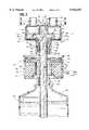
- FIG. 1is cross-sectional elevational view, partially broken away, illustrating a humidifier system embodying the principles of the present invention
- FIG. 2is an exploded cross-sectional elevational view, partially broken away, of the humidifier system of FIG. 1;
- FIG. 3is a horizontal plan view taken along the plane 3--3 in FIG. 2;
- FIG. 4is a horizontal cross-sectional view taken along the plane 4--4 in FIG. 1;
- FIG. 5is a horizontal cross-sectional view taken along the plane 5--5 in FIG. 1;
- FIG. 6is a horizontal cross-sectional view taken along the plane 6--6 in FIG. 1 illustrating an alternate embodiment of the tube and the wick of the present invention
- FIG. 7is a cross-sectional elevational view, partially broken away, illustrating the separation of the tube from the neck of the humidifier module during the priming of the humidifier system.
- FIG. 8is an elevational cross-sectional view, partially broken away, illustrating the interior of an alternate embodiment of the humidifier module of the present invention.
- a humidifier system embodying the present inventionis described hereinbelow in its usual vertical assembled position as shown in the accompanying drawings and terms such as upper, lower, horizontal, etc., will be used herein with reference to this usual position.
- the humidifier systemmay be manufactured, stored, transported and sold in orientations other than that described and shown herein.
- a humidifier device or system 10comprising a humidifier assembly 11 including a generally shell shaped humidifier module 12 having releasably secured thereto a generally cylindrically shaped heater module 14 and a liquid supply bottle 16.
- the humidifier assembly 11also includes an elongate tubular liquid supply or transport conduit 18 extending centrally through the humidifier system 10 and, more particularly, from the supply bottle 16, through the center of the heater module 14 and into the humidifier module 12.
- the humidifier module 12is comprised of a bodyshell 20 which defines an interior humidifying chamber 22.
- the bodyshell 20includes a flat generally circularly shaped top wall 24 having a tubular inlet port 26 in communication with the humidifying chamber 22 to which is connected a pressurized gas (oxygen) source (not shown) and a tubular outlet port 30 also in communication with the humidifying chamber 22 to which is connected a breathing apparatus (not shown).
- the inlet and outlet ports 26 and 30respectively are positioned along the central transverse axis of the humidifier module 12 and are diametrically opposed to each other.
- the humidifier module 12further includes a plate assembly 34 located within the interior of the humidifying chamber 22.
- Plate assembly 34includes a hollow tube 36 depending from the interior surface of the top wall 24 of the humidifier module 12 and extending inwardly into the humidifying chamber 22 along the longitudinal axis 37 of the humidifying system 10.
- An annular and planar unitary plate 38extends radially outwardly from the lower peripheral edge of the tube 36 and includes a central circular aperture 39 defined by the lower open end of the tube 36.
- a skirt or wall 40depends downwardly from, and extends circumferentially about, the lower peripheral annular edge of the plate 38.
- a heat transfer element 42is located at the lower end of the humidifier module 12 substantially normal to the longitudinal axis 37 of the humidifier system 10.
- the heat transfer element 42includes an annular, planar metal or ceramic disc 44 which is sealed about its peripheral outer edge to a depending cylindrical skirt portion 46 defined by the bodyshell 20 of the humidifier module 12.
- the disc 44defines a central circular aperture 48 which is substantially axially aligned with the longitudinal axis 37 of the humidifying system 10 and the central aperture 39 of the annular plate 38.
- the plate 38is spaced from and generally parallel to the heat transfer element 42.
- An annular, substantially planar absorbent disc 49is seated on and abuts the top surface of the heat transfer element 42.
- External threading 50is provided on the skirt portion 46 to allow threaded securement of the humidifier module 12 to the heater module 14.
- humidifier module 12further includes a tubular neck 52 in communication with the humidifying chamber 22 which is sealed to, and depends downwardly from, the central aperture 48 in the disc 44.
- the neck 52is aligned axially with, and extends along the length of, the longitudinal axis 37 of the humidifying system 10 and further is positioned concentrically with the central aperture 48 of the disc 44.
- a series of diametrically opposed slots 54may be provided at the upper end of the neck 52.
- a ring 55overlies the upper peripheral end of the neck 52 and the slots 54 therein.
- a funnel like chute 56depends from the upper end of the neck 52.
- the chute 56includes a conical wall 57 converging inwardly from the inner wall of the neck 52, a unitary cylindrical wall 58 extending downwardly from the conical wall 57 and a shoulder 59 defined therebetween.
- the neck 52defines an internally threaded portion 60. More particularly, the length of the neck 52 is sufficient to pass through a central opening 62 in the heater module 14 and threadably engage an upper end of the neck 64 of the supply bottle 16 when the modules comprising the humidifier system 10 are assembled together as shown in FIG. 1.
- the reusable heater module 14includes a cylindrical housing 66.
- An upper end of the housing 66defines an internally threaded portion 68 which coacts with the externally threaded portion 50 of the humidifier module 12 in a manner releasably securing the two modules together.
- the heater module 14further includes a heated platen 70, which overlies an electrically controlled heat source 72 and which defines a heated surface 74.
- the heated surface 74 of the platen 70is arranged in a heat transfer relationship with the annular disc 44 in the humidifier module 12 when the heater module 14 is releasably secured to the humidifier module 12 as shown in FIG. 1.
- the liquid supply bottle 16defines a reservoir 76 adapted to contain a sterile liquid, such as water, which may be medicated.
- a sterile liquidsuch as water
- the neck 64 of supply bottle 16includes an externally threaded portion 78 adapted for securement to the internally threaded portion 60 of the neck 52 of the humidifier module 12.
- the liquid supply or transport conduit 18 of humidifier assembly 11includes an elongate plastic tube 80 having a tubular hollow body 81 extending through the neck 52 of humidifier module 12, the central opening 62 in the heater module 14, the neck 64 of the supply bottle 16, and into the reservoir 76 of bottle 16.
- the tube 80includes a lower end 82 (FIG. 1) extending into and immersed in the liquid in the reservoir 76 and an upper flared tubular end 84 (FIG. 2).
- the flared end 84is defined by a peripheral tubular end wall 85 having a diameter slightly greater than the diameter of the body 81 so as to define a radial shoulder 86 between the end wall 85 and the body 81.
- the shoulder 86 of the flared end 84is seated over and abuts the shoulder 59 of the chute 56 so as to support the tube 80 in the neck 52 of the humidifier module 12.
- the end wall 85 of the tube 80is spaced from the conical wall 57 of the chute 56 and the body 81 of the tube 80 is spaced from the cylindrical wall 58 of the chute 56 so as to define a pressure equilibration passageway such as passageway 88 (FIG. 4) between the tube 80 and the chute 56.
- the flared end wall 85 of the tube 80is scalloped so as to define a plurality of relatively small optional spaces or apertures 89, between the shoulders 59 and 86 of the chute 54 and the flared end 84 of the tube 80 respectively, which communicate with the passageway 88 to define pressure equilibration passage 91 between the humidifying chamber 22 and the liquid reservoir 76.
- the size of apertures 89is no larger than what is needed to equalize the pressure in chamber 22 and liquid reservoir 76. Spaces or apertures 89 can be omitted if pressure equilibration can be achieved through wick 90 or by means of surface irregularities of flared end wall 85.
- the flared end wall 285 of the tube 280includes a plurality of circumferentially extending ridges 293 which also define a plurality of small passageways 289 between the chute 56 and the flared end 284 of the tube 280, respectively.
- the liquid supply or transport conduit 18further includes an elongate liquid absorbing member or wick 90 which extends through the interior of the tube 90.
- the wick 90comprises a plurality of elongate longitudinal strips 92 of absorbing material such as cotton or the like which have been twisted together longitudinally as shown in FIG. 2.
- the wick 290comprises an elongate sheet 292 of absorbing material such as cotton or the like which has been rolled up.
- the wick 90includes a lower planar and annular end 93 (FIG. 1) which is generally flush with the lower end 82 of the tube 80 and is thus immersed in the liquid in the reservoir 76.
- the wick 90also includes an upper end 94 having a plurality of diametrically opposed leaves 96.
- the leaves 96are defined by the upper peripheral ends of the strips 92.
- the leavesare formed by cutting the upper peripheral end of the sheet 292 into three pie shaped sections and then pulling the cut sections back away from the rolled sheet 292.
- the leaves 96extend from the end 94 of the wick 90 planarly and radially outwardly into the humidifying chamber 22 from the longitudinal axis 37 of the humidifier module 12.
- the leaves 96are positioned between and in contact with the skirt 40 of the plate 38 on one side and the absorbent disc 49 overlying the heat transfer element 42 on the lower side.
- Each of the leaves 96includes a tip portion 98 which extends beyond the skirt 40 of the plate 38 to the outer periphery of the humidifying module 12.
- the plate 38 and, more particularly, the skirt 40 thereofholds the leaves 96 in contact with the heat transfer element 42 so as to maximize the transfer of heat from the heat transfer element 42 to the leaves 96 as described below.
- the plate 38 shown in FIG. 2can be substituted with any other suitable type of assembly for holding the leaves 296 against the heat transfer element 242 such as spring assemblies 235 in the humidifying chamber 222.
- Each of the spring assemblies 235includes an upper end 237 abutting the bottom of the top wall 224 of the humidifying chamber 222 and a lower looped end 239 which is abutted against the tip 298 of the respective leafs 296 so as to hold the respective leafs 296 against the heat transfer element 242.
- the wick 90can optionally include a central aperture 100 extending therethrough along the longitudinal axis thereof which defines an additional vent passage between the humidifying chamber 22 and the reservoir 76.
- the wick 90In operation, and referring to FIG. 2, the wick 90 must initially be primed. This may be accomplished by inverting the humidifier system 10 or by squeezing the supply bottle 16 to cause the liquid in the reservoir 76 to be thoroughly absorbed into the wick 90 and cause the unseating of the tube 80 from the chute 54 which, in turn, causes the liquid to travel into the upper end of the neck 52 of the humidifying chamber 22 and into the bottom end of the humidifying chamber 22 where the liquid is absorbed by the leaves 96 of the wick 90. Alternatively, the wick 90 can be primed by pouring about 30 ml of the liquid into the humidifying chamber 22 through either the inlet or outlet ports 26 and 30 respectively.
- a stream of oxygen or the like oxygen-bearing supply gasis introduced through the inlet port 26 into the humidifying chamber 22.
- capillary actionallows liquid from the reservoir 76 to be continually transported up the wick 90 and into the leaves 96 thereof where the liquid is vaporized as a result of the transfer of heat from the heat transfer element 42 to the liquid in the leaves 96.
- the heated vaporis combined with the supply gas in the humidifying chamber 22 to create a heated and humidified breathing gas which is passed to the breathing apparatus through the outlet port 30. Any coalesced water formed on the disc 44 is fed into the drain channels defined by the slots 54 in the neck 52, through the vent opening 91 and then back into the reservoir 76.
- the present inventioneliminates the risk of overheating and overhumidifying because the amount of liquid which is vaporized is dependent upon the volumetric amount of supply gas introduced into the humidifying chamber 22. For example, if the volumetric rate of supply gas introduced into the humidifying chamber 22 is reduced, the local negative pressure in the reservoir 76 is reduced causing a reduction in the amount of liquid carried up through the wick 90, which causes a reduction in the amount of liquid absorbed in the leaves 96 of the wick 90 and thus a reduction in the amount of liquid which is vaporized into the humidifying chamber 22. Thus, a reduced heat and humidity output is automatically obtained to match the reduced flow rate thereby providing the self-regulating feature of the present invention.
- the breathing gasis advantageously maintained at a substantially constant temperature and humidity level regardless of any supply gas intake adjustments.
- the breathing gasis maintained at a temperature lower than body temperature.
- the maximum output temperatures at the patient end of a six foot hose at a room ambient temperature of 24° C.should be as follows:
Landscapes
- Health & Medical Sciences (AREA)
- Engineering & Computer Science (AREA)
- Heart & Thoracic Surgery (AREA)
- Animal Behavior & Ethology (AREA)
- Pulmonology (AREA)
- Veterinary Medicine (AREA)
- Anesthesiology (AREA)
- Biomedical Technology (AREA)
- Public Health (AREA)
- Hematology (AREA)
- Life Sciences & Earth Sciences (AREA)
- Emergency Medicine (AREA)
- General Health & Medical Sciences (AREA)
- Chemical & Material Sciences (AREA)
- Chemical Kinetics & Catalysis (AREA)
- Combustion & Propulsion (AREA)
- Mechanical Engineering (AREA)
- General Engineering & Computer Science (AREA)
- Air Humidification (AREA)
Abstract
Description
______________________________________Minute Supply GasVolume, liters Breathingper minute Gas(Avg. Flow) Temperature______________________________________ 5 37° C.10 34° C.15 32° C.______________________________________
Claims (18)
Priority Applications (1)
| Application Number | Priority Date | Filing Date | Title |
|---|---|---|---|
| US08/909,537US5916493A (en) | 1997-08-12 | 1997-08-12 | Humidifier system |
Applications Claiming Priority (1)
| Application Number | Priority Date | Filing Date | Title |
|---|---|---|---|
| US08/909,537US5916493A (en) | 1997-08-12 | 1997-08-12 | Humidifier system |
Publications (1)
| Publication Number | Publication Date |
|---|---|
| US5916493Atrue US5916493A (en) | 1999-06-29 |
Family
ID=25427404
Family Applications (1)
| Application Number | Title | Priority Date | Filing Date |
|---|---|---|---|
| US08/909,537Expired - LifetimeUS5916493A (en) | 1997-08-12 | 1997-08-12 | Humidifier system |
Country Status (1)
| Country | Link |
|---|---|
| US (1) | US5916493A (en) |
Cited By (57)
| Publication number | Priority date | Publication date | Assignee | Title |
|---|---|---|---|---|
| US6293474B1 (en) | 1999-03-08 | 2001-09-25 | S. C. Johnson & Son, Inc. | Delivery system for dispensing volatiles |
| US6446880B1 (en) | 2000-08-02 | 2002-09-10 | S.C. Johnson & Son, Inc. | Replaceable reservoir for an atomizing apparatus |
| US6550476B1 (en)* | 1998-05-21 | 2003-04-22 | Steven L. Ryder | Heat-moisture exchanger and nebulization device |
| US20040020487A1 (en)* | 2002-07-31 | 2004-02-05 | Jochim Koch | Breathing gas humidifier system for a patient |
| US20040055597A1 (en)* | 2001-02-16 | 2004-03-25 | Alexander Virr | Air pressure signal monitoring in apparatus for treating sleep disordered breathing |
| US6718973B2 (en)* | 2000-08-05 | 2004-04-13 | Dräger Medical AG & Co. KGaA | Evaporation chamber for a respiratory gas humidifier |
| US20040221843A1 (en)* | 2001-10-18 | 2004-11-11 | Martin Baecke | Evaporator, especially a respiratory humidifier, storage tank and casing therefor |
| US6827340B2 (en) | 2000-08-14 | 2004-12-07 | Taga Medical Technologies, Inc. | CPAP humidifier |
| US20050248045A1 (en)* | 2002-05-29 | 2005-11-10 | Jean-Michel Anthony | Device for heating and moistening breathing air |
| US20050263149A1 (en)* | 2002-09-19 | 2005-12-01 | Noymer Peter D | Aerosol drug delivery system employing formulation pre-heating |
| US20060043619A1 (en)* | 2002-11-12 | 2006-03-02 | Givaudan Sa | Powered dispensing devices for the delivery of evaporable materials |
| US20060220267A1 (en)* | 2005-03-29 | 2006-10-05 | Casio Computer Co., Ltd. | Vaporizing device and liquid absorbing member |
| US20080054497A1 (en)* | 2006-08-31 | 2008-03-06 | Medex Cardio-Pulmonary, Inc.. | Vented cap humidification system |
| US20080072900A1 (en)* | 2003-06-20 | 2008-03-27 | Resmed Limited | Breathable Gas Apparatus With Humidifier |
| US20090159079A1 (en)* | 2001-08-20 | 2009-06-25 | Map Medizin-Technologie Gmbh | Apparatus for supplying respiratory gas and a method for controlling the apparatus |
| US20090223514A1 (en)* | 2008-03-06 | 2009-09-10 | Resmed Limited | Humidification of respiratory gases |
| US20110023874A1 (en)* | 2009-07-31 | 2011-02-03 | Resmed Limited | Wire heated tube with temperature control system, tube type detection, and active over temperature protection for humidifier for respiratory apparatus |
| US20110073109A1 (en)* | 1999-08-05 | 2011-03-31 | Map Medizin-Technologie Gmbh | Apparatus for humidifying a respiratory gas |
| US20110180068A1 (en)* | 2003-06-20 | 2011-07-28 | Resmed Limited | Breathable gas apparatus with humidifier |
| WO2012025846A1 (en) | 2010-08-27 | 2012-03-01 | Koninklijke Philips Electronics N.V. | Portable humidification system and adaptor therefore |
| US20120073573A1 (en)* | 2000-03-21 | 2012-03-29 | Fisher & Paykel Healthcare Limited | Apparatus for delivering humidified gases |
| WO2012123854A1 (en)* | 2011-03-14 | 2012-09-20 | Koninklijke Philips Electronics N.V. | Humidifier with liquid ingress protection |
| US20120241987A1 (en)* | 2009-11-11 | 2012-09-27 | Seung Hyun Lee | Personal Portable Humidifier-Type Air Cleaner, and Case and Water Tank Thereof |
| USRE44453E1 (en) | 2001-02-16 | 2013-08-27 | Resmed Limited | Humidifier with structure to prevent backflow of liquid through the humidifier inlet |
| US20130239965A1 (en)* | 2010-01-15 | 2013-09-19 | Koninklijke Philips Electronics N.V. | Humidification system with signal transmission optimization |
| US20130303977A1 (en)* | 2003-06-12 | 2013-11-14 | Michael Spearman | Medical gas humidification system |
| US20140084497A1 (en)* | 2012-09-25 | 2014-03-27 | Chin-Cheng Huang | Thermal humidifier |
| US8789525B2 (en) | 2007-06-07 | 2014-07-29 | Resmed Limited | Tub for humidifier |
| CN105485816A (en)* | 2015-12-28 | 2016-04-13 | 安徽省华丰农产品专业合作社 | Variable-volume type USB air humidifier |
| CN105498062A (en)* | 2014-10-09 | 2016-04-20 | 台达电子工业股份有限公司 | Humidifying device for breathing mask |
| US9327093B2 (en) | 2007-07-31 | 2016-05-03 | Resmed Limited | Heating element, humidifier for respiratory apparatus including heating element, and respiratory apparatus |
| CN105698325A (en)* | 2015-12-28 | 2016-06-22 | 安徽省华丰农产品专业合作社 | Adjustable usb air humidifier |
| CN106039519A (en)* | 2016-07-08 | 2016-10-26 | 上海市杨浦区中心医院 | Oral humidifier for mouth breathing patients |
| US20160313016A1 (en)* | 2015-04-27 | 2016-10-27 | Crane USA Inc. | Portable air treatment system |
| US20170007798A1 (en)* | 2014-03-14 | 2017-01-12 | Fisher & Paykel Healthcare Limited | Humidification system |
| US9572949B2 (en) | 2013-02-01 | 2017-02-21 | Resmed Limited | Wire heated tube with temperature control system for humidifier for respiratory apparatus |
| US9578819B2 (en)* | 2013-01-24 | 2017-02-28 | Mark R Prescott | Pressurized growing air system for vertical and horizontal planting systems |
| US9610416B2 (en) | 2009-06-04 | 2017-04-04 | Resmed Limited | Flow generator chassis assembly with suspension seal |
| EP3302668A4 (en)* | 2015-06-02 | 2018-04-11 | Roger Foote | Medical humidifier |
| WO2018131918A1 (en)* | 2017-01-13 | 2018-07-19 | 박재상 | Heated humidifier |
| US10307559B2 (en) | 2011-01-24 | 2019-06-04 | Resmed Limited | Humidifier |
| KR101997593B1 (en)* | 2018-01-26 | 2019-07-08 | 박재상 | Heater for warming gas and method for manufacturing thereof |
| US10493233B1 (en)* | 2018-06-05 | 2019-12-03 | Duke University | Bi-directional access to tumors |
| US10518061B2 (en) | 2014-03-13 | 2019-12-31 | ResMed Pty Ltd | Humidifier for a respiratory therapy device |
| US10806889B2 (en) | 2008-06-05 | 2020-10-20 | ResMed Pty Ltd | Treatment of respiratory conditions |
| US10864343B2 (en) | 2013-12-17 | 2020-12-15 | ResMed Pty Ltd | Respiratory pressure treatment system |
| US10864346B2 (en) | 2015-03-05 | 2020-12-15 | ResMed Pty Ltd | Humidifier for a respiratory therapy device |
| CN112351806A (en)* | 2018-06-29 | 2021-02-09 | 皇家飞利浦有限公司 | Humidifier for a system for providing a flow of breathable gas |
| US11007340B2 (en) | 2004-08-20 | 2021-05-18 | Fisher & Paykel Healthcare Limited | Apparatus for measuring properties of gases supplied to a patient |
| US11013875B2 (en) | 2005-08-15 | 2021-05-25 | ResMed Pty Ltd | Low cost CPAP flow generator and humidifier assembly |
| US20210353899A1 (en)* | 2018-10-10 | 2021-11-18 | Daniel Schwarz | Water reservoir for a device for gas humidification in laparoscopy |
| US11602174B2 (en) | 2017-08-25 | 2023-03-14 | Nicoventures Trading Limited | Vapor provision systems |
| US11723405B2 (en) | 2016-09-28 | 2023-08-15 | Nicoventures Trading Limited | Liquid storage tank for a vapor provision system |
| US20240024613A1 (en)* | 2022-07-22 | 2024-01-25 | Covidien Lp | Low-profile humidifier with removable flow channel |
| US12194244B2 (en) | 2018-12-18 | 2025-01-14 | ResMed Pty Ltd | Humidifier reservoir |
| US12203195B2 (en) | 2017-08-25 | 2025-01-21 | Nicoventures Trading Limited | Vapor provision systems |
| US12420038B2 (en) | 2012-05-23 | 2025-09-23 | Fisher & Paykel Healthcare Limited | Flow path fault detection method for a respiratory assistance apparatus |
Citations (20)
| Publication number | Priority date | Publication date | Assignee | Title |
|---|---|---|---|---|
| US3592451A (en)* | 1969-03-12 | 1971-07-13 | Richard Lee Mcduffee | Absorbent pad structures for humidifiers |
| US3724180A (en)* | 1971-01-22 | 1973-04-03 | Environmental Ind Inc | Steam humidifier with centrifugal separator |
| US3804280A (en)* | 1971-07-27 | 1974-04-16 | Respiratory Care | Multi-use inhalation therapy apparatus |
| US3820540A (en)* | 1971-12-07 | 1974-06-28 | H Hirtz | Electrical appliance |
| US3846518A (en)* | 1972-06-19 | 1974-11-05 | American Hospital Supply Corp | Port system for medical humidifier container |
| US3903216A (en)* | 1969-09-10 | 1975-09-02 | Respiratory Care | Inhalation therapy apparatus |
| US4110419A (en)* | 1975-04-18 | 1978-08-29 | Respiratory Care, Inc. | High-volume disposable and semi-disposable cartridge humidifier with self-contained cartridge sterilizing means, and related method |
| US4225542A (en)* | 1978-12-12 | 1980-09-30 | Minnesota Mining And Manufacturing Company | Evaporative humidifier |
| US4419302A (en)* | 1979-09-29 | 1983-12-06 | Matsushita Electric Industrial Company, Limited | Steam generator |
| US4454877A (en)* | 1981-05-26 | 1984-06-19 | Andrew Boettner | Portable nebulizer or mist producing device |
| US4629590A (en)* | 1984-10-15 | 1986-12-16 | Cimco | Nebulizer |
| US4652408A (en)* | 1985-04-04 | 1987-03-24 | The Boc Group Plc | Inhalation apparatus |
| US4657713A (en)* | 1983-05-19 | 1987-04-14 | Intertech Resources Inc. | Heated respiratory therapy humidifier |
| US4674494A (en)* | 1985-05-10 | 1987-06-23 | The Kendall Company | Humidifying device |
| US4879997A (en)* | 1988-04-07 | 1989-11-14 | Bickford Allan M | Anesthetic vaporizer |
| US4911157A (en)* | 1988-01-07 | 1990-03-27 | Pegasus Research Corporation | Self-regulating, heated nebulizer system |
| US5067169A (en)* | 1990-08-01 | 1991-11-19 | Duracraft Corporation | Portable humidifier |
| US5195515A (en)* | 1991-03-06 | 1993-03-23 | Walter Levine | Heated cartridge humidifier and humidification chamber for use therewith |
| US5367604A (en)* | 1992-04-24 | 1994-11-22 | Fisher & Paykel Limited | Humidifier apparatus and/or gases distribution chambers and/or temperature probe |
| US5383447A (en)* | 1990-11-02 | 1995-01-24 | Lang; Volker | Device for warming and moistening gases having both an active and passive heat exchanger. |
- 1997
- 1997-08-12USUS08/909,537patent/US5916493A/ennot_activeExpired - Lifetime
Patent Citations (20)
| Publication number | Priority date | Publication date | Assignee | Title |
|---|---|---|---|---|
| US3592451A (en)* | 1969-03-12 | 1971-07-13 | Richard Lee Mcduffee | Absorbent pad structures for humidifiers |
| US3903216A (en)* | 1969-09-10 | 1975-09-02 | Respiratory Care | Inhalation therapy apparatus |
| US3724180A (en)* | 1971-01-22 | 1973-04-03 | Environmental Ind Inc | Steam humidifier with centrifugal separator |
| US3804280A (en)* | 1971-07-27 | 1974-04-16 | Respiratory Care | Multi-use inhalation therapy apparatus |
| US3820540A (en)* | 1971-12-07 | 1974-06-28 | H Hirtz | Electrical appliance |
| US3846518A (en)* | 1972-06-19 | 1974-11-05 | American Hospital Supply Corp | Port system for medical humidifier container |
| US4110419A (en)* | 1975-04-18 | 1978-08-29 | Respiratory Care, Inc. | High-volume disposable and semi-disposable cartridge humidifier with self-contained cartridge sterilizing means, and related method |
| US4225542A (en)* | 1978-12-12 | 1980-09-30 | Minnesota Mining And Manufacturing Company | Evaporative humidifier |
| US4419302A (en)* | 1979-09-29 | 1983-12-06 | Matsushita Electric Industrial Company, Limited | Steam generator |
| US4454877A (en)* | 1981-05-26 | 1984-06-19 | Andrew Boettner | Portable nebulizer or mist producing device |
| US4657713A (en)* | 1983-05-19 | 1987-04-14 | Intertech Resources Inc. | Heated respiratory therapy humidifier |
| US4629590A (en)* | 1984-10-15 | 1986-12-16 | Cimco | Nebulizer |
| US4652408A (en)* | 1985-04-04 | 1987-03-24 | The Boc Group Plc | Inhalation apparatus |
| US4674494A (en)* | 1985-05-10 | 1987-06-23 | The Kendall Company | Humidifying device |
| US4911157A (en)* | 1988-01-07 | 1990-03-27 | Pegasus Research Corporation | Self-regulating, heated nebulizer system |
| US4879997A (en)* | 1988-04-07 | 1989-11-14 | Bickford Allan M | Anesthetic vaporizer |
| US5067169A (en)* | 1990-08-01 | 1991-11-19 | Duracraft Corporation | Portable humidifier |
| US5383447A (en)* | 1990-11-02 | 1995-01-24 | Lang; Volker | Device for warming and moistening gases having both an active and passive heat exchanger. |
| US5195515A (en)* | 1991-03-06 | 1993-03-23 | Walter Levine | Heated cartridge humidifier and humidification chamber for use therewith |
| US5367604A (en)* | 1992-04-24 | 1994-11-22 | Fisher & Paykel Limited | Humidifier apparatus and/or gases distribution chambers and/or temperature probe |
Cited By (149)
| Publication number | Priority date | Publication date | Assignee | Title |
|---|---|---|---|---|
| US6550476B1 (en)* | 1998-05-21 | 2003-04-22 | Steven L. Ryder | Heat-moisture exchanger and nebulization device |
| US6293474B1 (en) | 1999-03-08 | 2001-09-25 | S. C. Johnson & Son, Inc. | Delivery system for dispensing volatiles |
| US9884163B2 (en) | 1999-08-05 | 2018-02-06 | RedMed R&D Germany GmbH | Apparatus for humidifying a respiratory gas |
| US9555211B2 (en) | 1999-08-05 | 2017-01-31 | Resmed R&D Germany Gmbh | Apparatus for humidifying a respiratory gas |
| US9545494B2 (en) | 1999-08-05 | 2017-01-17 | Resmed R&D Germany Gmbh | Apparatus for humidifying a respiratory gas |
| US10052450B2 (en) | 1999-08-05 | 2018-08-21 | Resmed R&D Germany Gmbh | Apparatus for humidifying a respiratory gas |
| US8469025B2 (en) | 1999-08-05 | 2013-06-25 | Resmed R&D Germany Gmbh | Apparatus for humidifying a respiratory gas |
| US20110073109A1 (en)* | 1999-08-05 | 2011-03-31 | Map Medizin-Technologie Gmbh | Apparatus for humidifying a respiratory gas |
| US9545493B2 (en) | 1999-08-05 | 2017-01-17 | Resmed R&D Germany Gmbh | Apparatus for humidifying a respiratory gas |
| US9302067B2 (en) | 1999-08-05 | 2016-04-05 | Resmed R&D Germany Gmbh | Apparatus for humidifying a respiratory gas |
| US9272116B2 (en) | 1999-08-05 | 2016-03-01 | Resmed R&D Germany Gmbh | Apparatus for humidifying a respiratory gas |
| US20120073573A1 (en)* | 2000-03-21 | 2012-03-29 | Fisher & Paykel Healthcare Limited | Apparatus for delivering humidified gases |
| US8550072B2 (en)* | 2000-03-21 | 2013-10-08 | Fisher & Paykel Healthcare Limited | Apparatus for delivering humidified gases |
| US6446880B1 (en) | 2000-08-02 | 2002-09-10 | S.C. Johnson & Son, Inc. | Replaceable reservoir for an atomizing apparatus |
| US6718973B2 (en)* | 2000-08-05 | 2004-04-13 | Dräger Medical AG & Co. KGaA | Evaporation chamber for a respiratory gas humidifier |
| US6827340B2 (en) | 2000-08-14 | 2004-12-07 | Taga Medical Technologies, Inc. | CPAP humidifier |
| USRE46079E1 (en) | 2001-02-16 | 2016-07-26 | Resmed Limited | Humidifier with structure to prevent backflow of liquid through the humidifier inlet |
| USRE48118E1 (en) | 2001-02-16 | 2020-07-28 | ResMed Pty Ltd | Humidifier with structure to prevent backflow of liquid through the humidifier inlet |
| USRE48095E1 (en) | 2001-02-16 | 2020-07-14 | ResMed Pty Ltd | Humidifier with structure to prevent backflow of liquid through the humidifier inlet |
| CN1304068C (en)* | 2001-02-16 | 2007-03-14 | 雷斯梅德有限公司 | Air pressure signal monitoring in apparatus for treating sleep disordered breathing |
| US7137388B2 (en) | 2001-02-16 | 2006-11-21 | Resmed Limited | Air pressure signal monitoring in apparatus for treating sleep disordered breathing |
| USRE48149E1 (en) | 2001-02-16 | 2020-08-11 | ResMed Pty Ltd | Humidifier with structure to prevent backflow of liquid through the humidifier inlet |
| EP1359963A4 (en)* | 2001-02-16 | 2005-05-04 | Resmed Ltd | Air pressure signal monitoring in apparatus for treating sleep disordered breathing |
| USRE46571E1 (en) | 2001-02-16 | 2017-10-17 | Resmed Limited | Humidifier with structure to prevent backflow of liquid through the humidifier inlet |
| US20040055597A1 (en)* | 2001-02-16 | 2004-03-25 | Alexander Virr | Air pressure signal monitoring in apparatus for treating sleep disordered breathing |
| USRE44453E1 (en) | 2001-02-16 | 2013-08-27 | Resmed Limited | Humidifier with structure to prevent backflow of liquid through the humidifier inlet |
| US20090159079A1 (en)* | 2001-08-20 | 2009-06-25 | Map Medizin-Technologie Gmbh | Apparatus for supplying respiratory gas and a method for controlling the apparatus |
| US8671936B2 (en) | 2001-08-20 | 2014-03-18 | Resmed R&D Germany Gmbh | Apparatus for supplying respiratory gas and a method for controlling the apparatus |
| US10112027B2 (en) | 2001-08-20 | 2018-10-30 | Resmed R&D Germany Gmbh | Apparatus for supplying respiratory gas and a method for controlling the apparatus |
| US20110220105A1 (en)* | 2001-08-20 | 2011-09-15 | Map Medizin-Technologie Gmbh | Apparatus for supplying respiratory gas and a method for controlling the apparatus |
| US7997270B2 (en) | 2001-08-20 | 2011-08-16 | Map Medizin-Technologie Gmbh | Apparatus for supplying respiratory gas and a method for controlling the apparatus |
| US20040221843A1 (en)* | 2001-10-18 | 2004-11-11 | Martin Baecke | Evaporator, especially a respiratory humidifier, storage tank and casing therefor |
| US7322566B2 (en)* | 2002-05-29 | 2008-01-29 | Bvba Medisize Belgie | Device for heating and moistening breathing air |
| US20050248045A1 (en)* | 2002-05-29 | 2005-11-10 | Jean-Michel Anthony | Device for heating and moistening breathing air |
| US6997183B2 (en)* | 2002-07-31 | 2006-02-14 | Dräger Medical AG & Co. KGaA | Breathing gas humidifier system for a patient |
| US20040020487A1 (en)* | 2002-07-31 | 2004-02-05 | Jochim Koch | Breathing gas humidifier system for a patient |
| US20050263149A1 (en)* | 2002-09-19 | 2005-12-01 | Noymer Peter D | Aerosol drug delivery system employing formulation pre-heating |
| US20060043619A1 (en)* | 2002-11-12 | 2006-03-02 | Givaudan Sa | Powered dispensing devices for the delivery of evaporable materials |
| US8945040B2 (en)* | 2003-06-12 | 2015-02-03 | Lexion Medical Llc | Medical gas humidification system |
| US20130303977A1 (en)* | 2003-06-12 | 2013-11-14 | Michael Spearman | Medical gas humidification system |
| USRE46543E1 (en) | 2003-06-20 | 2017-09-12 | Resmed Limited | Breathable gas apparatus with humidifier |
| US9539409B2 (en) | 2003-06-20 | 2017-01-10 | Resmed Limited | Breathable gas apparatus with humidifier |
| US11235115B2 (en) | 2003-06-20 | 2022-02-01 | ResMed Pty Ltd | Breathable gas apparatus with humidifier |
| US11260187B2 (en) | 2003-06-20 | 2022-03-01 | ResMed Pty Ltd | Breathable gas supply apparatus |
| US10881820B2 (en) | 2003-06-20 | 2021-01-05 | ResMed Pty Ltd | Breathable gas apparatus with humidifier |
| US11413412B2 (en) | 2003-06-20 | 2022-08-16 | ResMed Pty Ltd | Breathable gas supply apparatus |
| US10850053B2 (en) | 2003-06-20 | 2020-12-01 | ResMed Pty Ltd | Breathable gas supply apparatus |
| US20080072900A1 (en)* | 2003-06-20 | 2008-03-27 | Resmed Limited | Breathable Gas Apparatus With Humidifier |
| US9038632B2 (en) | 2003-06-20 | 2015-05-26 | Resmed Limited | Breathable gas apparatus with humidifier |
| US9038631B2 (en) | 2003-06-20 | 2015-05-26 | Resmed Limited | Breathable gas apparatus with humidifier |
| US10293125B2 (en) | 2003-06-20 | 2019-05-21 | Resmed Limited | Flow generator with patient reminder |
| US9072860B2 (en) | 2003-06-20 | 2015-07-07 | Resmed Limited | Breathable gas apparatus with humidifier |
| US9227035B2 (en) | 2003-06-20 | 2016-01-05 | Resmed Limited | Breathable gas apparatus with humidifier |
| US10201676B2 (en) | 2003-06-20 | 2019-02-12 | Resmed Limited | Breathable gas supply apparatus |
| US20100192094A1 (en)* | 2003-06-20 | 2010-07-29 | Resmed Limited | Flow generator with patient reminder |
| US8042535B2 (en) | 2003-06-20 | 2011-10-25 | Resmed Limited | Breathable gas apparatus with humidifier |
| US9610420B2 (en) | 2003-06-20 | 2017-04-04 | Resmed Limited | Breathable gas apparatus with humidifier |
| US20110180068A1 (en)* | 2003-06-20 | 2011-07-28 | Resmed Limited | Breathable gas apparatus with humidifier |
| US8006691B2 (en) | 2003-06-20 | 2011-08-30 | Resmed Limited | Humidifier with removable water tank |
| US9358359B2 (en) | 2003-06-20 | 2016-06-07 | Resmed Limited | Breathable gas apparatus with humidifier |
| US8020551B2 (en) | 2003-06-20 | 2011-09-20 | Resmed Limited | Breathable gas apparatus with humidifier |
| US8028693B2 (en) | 2003-06-20 | 2011-10-04 | Resmed Limited | Breathable gas apparatus with humidifier |
| US11458273B2 (en) | 2004-08-20 | 2022-10-04 | Fisher & Paykel Healthcare Limited | Apparatus for measuring properties of gases supplied to a patient |
| US11007340B2 (en) | 2004-08-20 | 2021-05-18 | Fisher & Paykel Healthcare Limited | Apparatus for measuring properties of gases supplied to a patient |
| US11679224B2 (en) | 2004-08-20 | 2023-06-20 | Fisher & Paykel Healthcare Limited | Apparatus for measuring properties of gases supplied to a patient |
| US11911564B2 (en) | 2004-08-20 | 2024-02-27 | Fisher & Paykel Healthcare Limited | Apparatus for measuring properties of gases supplied to a patient |
| US20060220267A1 (en)* | 2005-03-29 | 2006-10-05 | Casio Computer Co., Ltd. | Vaporizing device and liquid absorbing member |
| US7712729B2 (en)* | 2005-03-29 | 2010-05-11 | Casio Computer Co., Ltd. | Vaporizing device and liquid absorbing member |
| US11013875B2 (en) | 2005-08-15 | 2021-05-25 | ResMed Pty Ltd | Low cost CPAP flow generator and humidifier assembly |
| US12409283B2 (en) | 2005-08-15 | 2025-09-09 | Resmed Pty, Ltd. | Low cost CPAP flow generator and humidifier assembly |
| US11298482B2 (en) | 2005-08-15 | 2022-04-12 | ResMed Pty Ltd | Low cost CPAP flow generator and humidifier assembly |
| US20080054497A1 (en)* | 2006-08-31 | 2008-03-06 | Medex Cardio-Pulmonary, Inc.. | Vented cap humidification system |
| WO2008027669A3 (en)* | 2006-08-31 | 2008-06-19 | Medex Cardio Pulmonary Inc | Vented cap humidification system |
| US12011545B2 (en) | 2007-06-07 | 2024-06-18 | ResMed Pty Ltd | Tub for humidifier |
| US10478585B2 (en) | 2007-06-07 | 2019-11-19 | ResMed Pty Ltd | Tub for humidifier |
| US8789525B2 (en) | 2007-06-07 | 2014-07-29 | Resmed Limited | Tub for humidifier |
| US9327093B2 (en) | 2007-07-31 | 2016-05-03 | Resmed Limited | Heating element, humidifier for respiratory apparatus including heating element, and respiratory apparatus |
| US20090223514A1 (en)* | 2008-03-06 | 2009-09-10 | Resmed Limited | Humidification of respiratory gases |
| US9802022B2 (en) | 2008-03-06 | 2017-10-31 | Resmed Limited | Humidification of respiratory gases |
| US11229766B2 (en) | 2008-06-05 | 2022-01-25 | ResMed Pty Ltd | Treatment of respiratory conditions |
| US11878123B2 (en) | 2008-06-05 | 2024-01-23 | ResMed Pty Ltd | Treatment of respiratory conditions |
| US11433213B2 (en) | 2008-06-05 | 2022-09-06 | ResMed Pty Ltd | Treatment of respiratory conditions |
| US11247019B2 (en) | 2008-06-05 | 2022-02-15 | ResMed Pty Ltd | Treatment of respiratory conditions |
| US10806889B2 (en) | 2008-06-05 | 2020-10-20 | ResMed Pty Ltd | Treatment of respiratory conditions |
| US11129948B2 (en) | 2009-06-04 | 2021-09-28 | ResMed Pty Ltd | Flow generator chassis assembly with suspension seal |
| US12161800B2 (en) | 2009-06-04 | 2024-12-10 | ResMed Pty Ltd | Flow generator chassis assembly with suspension seal |
| US9610416B2 (en) | 2009-06-04 | 2017-04-04 | Resmed Limited | Flow generator chassis assembly with suspension seal |
| US12201768B2 (en) | 2009-07-31 | 2025-01-21 | ResMed Pty Ltd | Wire heated tube with temperature control system, tube type detection, and active over temperature protection for humidifier for respiratory apparatus |
| US8733349B2 (en) | 2009-07-31 | 2014-05-27 | Resmed Limited | Wire heated tube with temperature control system, tube type detection, and active over temperature protection for humidifier for respiratory apparatus |
| US10086158B2 (en) | 2009-07-31 | 2018-10-02 | Resmed Limited | Wire heated tube with temperature control system, tube type detection, and active over temperature protection for humidifier for respiratory apparatus |
| US11607512B2 (en) | 2009-07-31 | 2023-03-21 | ResMed Pty Ltd | Wire heated tube with temperature control system, tube type detection, and active over temperature protection for humidifier for respiratory apparatus |
| US11707587B2 (en) | 2009-07-31 | 2023-07-25 | ResMed Pty Ltd | Wire heated tube with temperature control system, tube type detection, and active over temperature protection for humidifier for respiratory apparatus |
| US11033698B2 (en) | 2009-07-31 | 2021-06-15 | ResMed Pty Ltd | Wire heated tube with temperature control system, tube type detection, and active over temperature protection for humidifier for respiratory apparatus |
| US20110023874A1 (en)* | 2009-07-31 | 2011-02-03 | Resmed Limited | Wire heated tube with temperature control system, tube type detection, and active over temperature protection for humidifier for respiratory apparatus |
| US9423142B2 (en)* | 2009-11-11 | 2016-08-23 | Seung Hyun Lee | Personal portable humidifier-type air cleaner, and case and water tank thereof |
| US20120241987A1 (en)* | 2009-11-11 | 2012-09-27 | Seung Hyun Lee | Personal Portable Humidifier-Type Air Cleaner, and Case and Water Tank Thereof |
| US20130239965A1 (en)* | 2010-01-15 | 2013-09-19 | Koninklijke Philips Electronics N.V. | Humidification system with signal transmission optimization |
| WO2012025846A1 (en) | 2010-08-27 | 2012-03-01 | Koninklijke Philips Electronics N.V. | Portable humidification system and adaptor therefore |
| US10307559B2 (en) | 2011-01-24 | 2019-06-04 | Resmed Limited | Humidifier |
| US11744979B2 (en) | 2011-01-24 | 2023-09-05 | ResMed Pty Ltd | Humidifier |
| CN103429293A (en)* | 2011-03-14 | 2013-12-04 | 皇家飞利浦有限公司 | Humidifier with liquid ingress protection |
| WO2012123854A1 (en)* | 2011-03-14 | 2012-09-20 | Koninklijke Philips Electronics N.V. | Humidifier with liquid ingress protection |
| CN103429293B (en)* | 2011-03-14 | 2016-02-24 | 皇家飞利浦有限公司 | There is the humidifier of feed liquor protection |
| US9545492B2 (en) | 2011-03-14 | 2017-01-17 | Koninklijke Philips N.V. | Humidifier with liquid ingress protection |
| US12420038B2 (en) | 2012-05-23 | 2025-09-23 | Fisher & Paykel Healthcare Limited | Flow path fault detection method for a respiratory assistance apparatus |
| US9057531B2 (en)* | 2012-09-25 | 2015-06-16 | Chin-Cheng Huang | Thermal humidifier |
| US20140084497A1 (en)* | 2012-09-25 | 2014-03-27 | Chin-Cheng Huang | Thermal humidifier |
| US9578819B2 (en)* | 2013-01-24 | 2017-02-28 | Mark R Prescott | Pressurized growing air system for vertical and horizontal planting systems |
| USRE50461E1 (en)* | 2013-01-24 | 2025-06-24 | Air8Green, Llc | Pressurized growing air system for vertical and horizontal planting systems |
| US11260186B2 (en) | 2013-02-01 | 2022-03-01 | ResMed Pty Ltd | Wire heated tube with temperature control system for humidifier for respiratory apparatus |
| US11779719B2 (en) | 2013-02-01 | 2023-10-10 | ResMed Pty Ltd | Wire heated tube with temperature control system for humidifier for respiratory apparatus |
| US9572949B2 (en) | 2013-02-01 | 2017-02-21 | Resmed Limited | Wire heated tube with temperature control system for humidifier for respiratory apparatus |
| US10363382B2 (en) | 2013-02-01 | 2019-07-30 | ResMed Pty Ltd | Wire heated tube with temperature control system for humidifier for respiratory apparatus |
| US11389615B2 (en) | 2013-12-17 | 2022-07-19 | ResMed Pty Ltd | Respiratory pressure treatment system |
| US11400251B2 (en) | 2013-12-17 | 2022-08-02 | ResMed Pty Ltd | Respiratory pressure treatment system |
| US11219735B1 (en) | 2013-12-17 | 2022-01-11 | ResMed Pty Ltd | Respiratory pressure treatment system |
| US11759595B2 (en) | 2013-12-17 | 2023-09-19 | ResMed Pty Ltd | Respiratory pressure treatment system |
| US11058845B2 (en) | 2013-12-17 | 2021-07-13 | ResMed Pty Ltd | Respiratory pressure treatment system |
| US12226584B2 (en) | 2013-12-17 | 2025-02-18 | ResMed Pty Ltd | Respiratory pressure treatment system |
| US10864343B2 (en) | 2013-12-17 | 2020-12-15 | ResMed Pty Ltd | Respiratory pressure treatment system |
| US11219736B1 (en) | 2013-12-17 | 2022-01-11 | ResMed Pty Ltd | Respiratory pressure treatment system |
| US10518061B2 (en) | 2014-03-13 | 2019-12-31 | ResMed Pty Ltd | Humidifier for a respiratory therapy device |
| US11813405B2 (en) | 2014-03-13 | 2023-11-14 | ResMed Pty Ltd | Humidifier for a respiratory therapy device |
| US10874819B2 (en)* | 2014-03-14 | 2020-12-29 | Fisher & Paykel Healthcare Limited | Humidification system |
| US20170007798A1 (en)* | 2014-03-14 | 2017-01-12 | Fisher & Paykel Healthcare Limited | Humidification system |
| CN105498062A (en)* | 2014-10-09 | 2016-04-20 | 台达电子工业股份有限公司 | Humidifying device for breathing mask |
| US10864346B2 (en) | 2015-03-05 | 2020-12-15 | ResMed Pty Ltd | Humidifier for a respiratory therapy device |
| US20160313016A1 (en)* | 2015-04-27 | 2016-10-27 | Crane USA Inc. | Portable air treatment system |
| US9845962B2 (en)* | 2015-04-27 | 2017-12-19 | Crane USA Inc. | Portable air treatment system |
| CN107921233B (en)* | 2015-06-02 | 2021-01-29 | 罗杰·富特 | Medical humidifier |
| CN107921233A (en)* | 2015-06-02 | 2018-04-17 | 罗杰·富特 | Medical humidifier |
| EP3302668A4 (en)* | 2015-06-02 | 2018-04-11 | Roger Foote | Medical humidifier |
| CN105485816B (en)* | 2015-12-28 | 2018-09-25 | 安徽省华丰农产品专业合作社 | Variable capacity type usb air humidifier |
| CN105698325A (en)* | 2015-12-28 | 2016-06-22 | 安徽省华丰农产品专业合作社 | Adjustable usb air humidifier |
| CN105485816A (en)* | 2015-12-28 | 2016-04-13 | 安徽省华丰农产品专业合作社 | Variable-volume type USB air humidifier |
| CN106039519A (en)* | 2016-07-08 | 2016-10-26 | 上海市杨浦区中心医院 | Oral humidifier for mouth breathing patients |
| US11723405B2 (en) | 2016-09-28 | 2023-08-15 | Nicoventures Trading Limited | Liquid storage tank for a vapor provision system |
| WO2018131918A1 (en)* | 2017-01-13 | 2018-07-19 | 박재상 | Heated humidifier |
| US12203195B2 (en) | 2017-08-25 | 2025-01-21 | Nicoventures Trading Limited | Vapor provision systems |
| US11602174B2 (en) | 2017-08-25 | 2023-03-14 | Nicoventures Trading Limited | Vapor provision systems |
| KR101997593B1 (en)* | 2018-01-26 | 2019-07-08 | 박재상 | Heater for warming gas and method for manufacturing thereof |
| WO2019147109A3 (en)* | 2018-01-26 | 2019-09-12 | 박재상 | Heater for heating gas and method of manufacturing same |
| US10493233B1 (en)* | 2018-06-05 | 2019-12-03 | Duke University | Bi-directional access to tumors |
| US11648366B2 (en)* | 2018-06-29 | 2023-05-16 | Koninklijke Philips N.V. | Humidifier for a system for providing a flow of breathable gas |
| CN112351806A (en)* | 2018-06-29 | 2021-02-09 | 皇家飞利浦有限公司 | Humidifier for a system for providing a flow of breathable gas |
| US20210113802A1 (en)* | 2018-06-29 | 2021-04-22 | Koninklijke Philips N.V. | Humidifier for a system for providing a flow of breathable gas |
| US20210353899A1 (en)* | 2018-10-10 | 2021-11-18 | Daniel Schwarz | Water reservoir for a device for gas humidification in laparoscopy |
| US12194244B2 (en) | 2018-12-18 | 2025-01-14 | ResMed Pty Ltd | Humidifier reservoir |
| US20240024613A1 (en)* | 2022-07-22 | 2024-01-25 | Covidien Lp | Low-profile humidifier with removable flow channel |
Similar Documents
| Publication | Publication Date | Title |
|---|---|---|
| US5916493A (en) | Humidifier system | |
| US4911157A (en) | Self-regulating, heated nebulizer system | |
| US4195044A (en) | Humidifier-nebulizer | |
| US4532088A (en) | Heated respiratory therapy humidifier | |
| US4657713A (en) | Heated respiratory therapy humidifier | |
| US12226585B2 (en) | Humidifier for breathing gas heating and humidification system | |
| US5259370A (en) | Nebulizer heater | |
| US3864326A (en) | Spraying devices, in particular nebulizing devices | |
| US4366105A (en) | High volume humidifier-nebulizer | |
| US5461695A (en) | Nebulizing assembly with heating equipment | |
| US4177945A (en) | Humidifier unit | |
| US5195515A (en) | Heated cartridge humidifier and humidification chamber for use therewith | |
| US4910384A (en) | Position independent humidifier apparatus | |
| US5063921A (en) | Nebulizer heater | |
| US3915386A (en) | Nebulizer | |
| US4061698A (en) | Humidifier-nebulizer apparatus | |
| JP2812513B2 (en) | Nebulizer device | |
| USRE30285E (en) | Spraying devices, in particular nebulizing devices | |
| US20200016344A1 (en) | Portable device for inhalation of at least one active composition | |
| CN103209728B (en) | Compact, low flow resistance aerosol generator and method of operation thereof | |
| US4500480A (en) | Pediatric cartridge humidifier | |
| US3990442A (en) | Respiratory treatment device | |
| US3954920A (en) | Gas humidification system | |
| US4172105A (en) | Pediatric cartridge humidifier | |
| US4036919A (en) | Nebulizer-humidifier system |
Legal Events
| Date | Code | Title | Description |
|---|---|---|---|
| AS | Assignment | Owner name:PEGASUS RESEARCH CORPORATION, CALIFORNIA Free format text:ASSIGNMENT OF ASSIGNORS INTEREST;ASSIGNOR:MILLER, KENNETH G.;REEL/FRAME:009232/0299 Effective date:19980116 | |
| STCF | Information on status: patent grant | Free format text:PATENTED CASE | |
| FPAY | Fee payment | Year of fee payment:4 | |
| AS | Assignment | Owner name:DHD HEALTHCARE CORPORATION, NEW YORK Free format text:ASSIGNMENT OF ASSIGNORS INTEREST;ASSIGNOR:PEGASUS RESEARCH CORPORATION;REEL/FRAME:014556/0511 Effective date:20030826 | |
| FEPP | Fee payment procedure | Free format text:PAT HOLDER NO LONGER CLAIMS SMALL ENTITY STATUS, ENTITY STATUS SET TO UNDISCOUNTED (ORIGINAL EVENT CODE: STOL); ENTITY STATUS OF PATENT OWNER: LARGE ENTITY | |
| AS | Assignment | Owner name:SMITHS MEDICAL ASD, INC., NEW HAMPSHIRE Free format text:MERGER;ASSIGNOR:DHD HEALTHCARE CORPORATION;REEL/FRAME:017045/0164 Effective date:20041217 | |
| FPAY | Fee payment | Year of fee payment:8 | |
| FPAY | Fee payment | Year of fee payment:12 |