US5916269A - Wear reduced acetabular component - Google Patents
Wear reduced acetabular componentDownload PDFInfo
- Publication number
- US5916269A US5916269AUS08/656,780US65678096AUS5916269AUS 5916269 AUS5916269 AUS 5916269AUS 65678096 AUS65678096 AUS 65678096AUS 5916269 AUS5916269 AUS 5916269A
- Authority
- US
- United States
- Prior art keywords
- bearing
- interrupted
- face
- component
- articular
- Prior art date
- Legal status (The legal status is an assumption and is not a legal conclusion. Google has not performed a legal analysis and makes no representation as to the accuracy of the status listed.)
- Expired - Lifetime
Links
Images


Classifications
- A—HUMAN NECESSITIES
- A61—MEDICAL OR VETERINARY SCIENCE; HYGIENE
- A61F—FILTERS IMPLANTABLE INTO BLOOD VESSELS; PROSTHESES; DEVICES PROVIDING PATENCY TO, OR PREVENTING COLLAPSING OF, TUBULAR STRUCTURES OF THE BODY, e.g. STENTS; ORTHOPAEDIC, NURSING OR CONTRACEPTIVE DEVICES; FOMENTATION; TREATMENT OR PROTECTION OF EYES OR EARS; BANDAGES, DRESSINGS OR ABSORBENT PADS; FIRST-AID KITS
- A61F2/00—Filters implantable into blood vessels; Prostheses, i.e. artificial substitutes or replacements for parts of the body; Appliances for connecting them with the body; Devices providing patency to, or preventing collapsing of, tubular structures of the body, e.g. stents
- A61F2/02—Prostheses implantable into the body
- A61F2/30—Joints
- A61F2/30767—Special external or bone-contacting surface, e.g. coating for improving bone ingrowth
- A61F2/30771—Special external or bone-contacting surface, e.g. coating for improving bone ingrowth applied in original prostheses, e.g. holes or grooves
- A—HUMAN NECESSITIES
- A61—MEDICAL OR VETERINARY SCIENCE; HYGIENE
- A61F—FILTERS IMPLANTABLE INTO BLOOD VESSELS; PROSTHESES; DEVICES PROVIDING PATENCY TO, OR PREVENTING COLLAPSING OF, TUBULAR STRUCTURES OF THE BODY, e.g. STENTS; ORTHOPAEDIC, NURSING OR CONTRACEPTIVE DEVICES; FOMENTATION; TREATMENT OR PROTECTION OF EYES OR EARS; BANDAGES, DRESSINGS OR ABSORBENT PADS; FIRST-AID KITS
- A61F2/00—Filters implantable into blood vessels; Prostheses, i.e. artificial substitutes or replacements for parts of the body; Appliances for connecting them with the body; Devices providing patency to, or preventing collapsing of, tubular structures of the body, e.g. stents
- A61F2/02—Prostheses implantable into the body
- A61F2/30—Joints
- A61F2/32—Joints for the hip
- A61F2/34—Acetabular cups
- A—HUMAN NECESSITIES
- A61—MEDICAL OR VETERINARY SCIENCE; HYGIENE
- A61F—FILTERS IMPLANTABLE INTO BLOOD VESSELS; PROSTHESES; DEVICES PROVIDING PATENCY TO, OR PREVENTING COLLAPSING OF, TUBULAR STRUCTURES OF THE BODY, e.g. STENTS; ORTHOPAEDIC, NURSING OR CONTRACEPTIVE DEVICES; FOMENTATION; TREATMENT OR PROTECTION OF EYES OR EARS; BANDAGES, DRESSINGS OR ABSORBENT PADS; FIRST-AID KITS
- A61F2/00—Filters implantable into blood vessels; Prostheses, i.e. artificial substitutes or replacements for parts of the body; Appliances for connecting them with the body; Devices providing patency to, or preventing collapsing of, tubular structures of the body, e.g. stents
- A61F2/02—Prostheses implantable into the body
- A61F2/30—Joints
- A61F2/32—Joints for the hip
- A61F2/36—Femoral heads ; Femoral endoprostheses
- A61F2/3609—Femoral heads or necks; Connections of endoprosthetic heads or necks to endoprosthetic femoral shafts
- A—HUMAN NECESSITIES
- A61—MEDICAL OR VETERINARY SCIENCE; HYGIENE
- A61F—FILTERS IMPLANTABLE INTO BLOOD VESSELS; PROSTHESES; DEVICES PROVIDING PATENCY TO, OR PREVENTING COLLAPSING OF, TUBULAR STRUCTURES OF THE BODY, e.g. STENTS; ORTHOPAEDIC, NURSING OR CONTRACEPTIVE DEVICES; FOMENTATION; TREATMENT OR PROTECTION OF EYES OR EARS; BANDAGES, DRESSINGS OR ABSORBENT PADS; FIRST-AID KITS
- A61F2/00—Filters implantable into blood vessels; Prostheses, i.e. artificial substitutes or replacements for parts of the body; Appliances for connecting them with the body; Devices providing patency to, or preventing collapsing of, tubular structures of the body, e.g. stents
- A61F2/02—Prostheses implantable into the body
- A61F2/30—Joints
- A61F2/38—Joints for elbows or knees
- A61F2/3859—Femoral components
- A—HUMAN NECESSITIES
- A61—MEDICAL OR VETERINARY SCIENCE; HYGIENE
- A61F—FILTERS IMPLANTABLE INTO BLOOD VESSELS; PROSTHESES; DEVICES PROVIDING PATENCY TO, OR PREVENTING COLLAPSING OF, TUBULAR STRUCTURES OF THE BODY, e.g. STENTS; ORTHOPAEDIC, NURSING OR CONTRACEPTIVE DEVICES; FOMENTATION; TREATMENT OR PROTECTION OF EYES OR EARS; BANDAGES, DRESSINGS OR ABSORBENT PADS; FIRST-AID KITS
- A61F2/00—Filters implantable into blood vessels; Prostheses, i.e. artificial substitutes or replacements for parts of the body; Appliances for connecting them with the body; Devices providing patency to, or preventing collapsing of, tubular structures of the body, e.g. stents
- A61F2/02—Prostheses implantable into the body
- A61F2/30—Joints
- A61F2/38—Joints for elbows or knees
- A61F2/3877—Patellae or trochleae
- A—HUMAN NECESSITIES
- A61—MEDICAL OR VETERINARY SCIENCE; HYGIENE
- A61F—FILTERS IMPLANTABLE INTO BLOOD VESSELS; PROSTHESES; DEVICES PROVIDING PATENCY TO, OR PREVENTING COLLAPSING OF, TUBULAR STRUCTURES OF THE BODY, e.g. STENTS; ORTHOPAEDIC, NURSING OR CONTRACEPTIVE DEVICES; FOMENTATION; TREATMENT OR PROTECTION OF EYES OR EARS; BANDAGES, DRESSINGS OR ABSORBENT PADS; FIRST-AID KITS
- A61F2/00—Filters implantable into blood vessels; Prostheses, i.e. artificial substitutes or replacements for parts of the body; Appliances for connecting them with the body; Devices providing patency to, or preventing collapsing of, tubular structures of the body, e.g. stents
- A61F2/02—Prostheses implantable into the body
- A61F2/30—Joints
- A61F2/38—Joints for elbows or knees
- A61F2/389—Tibial components
- A—HUMAN NECESSITIES
- A61—MEDICAL OR VETERINARY SCIENCE; HYGIENE
- A61F—FILTERS IMPLANTABLE INTO BLOOD VESSELS; PROSTHESES; DEVICES PROVIDING PATENCY TO, OR PREVENTING COLLAPSING OF, TUBULAR STRUCTURES OF THE BODY, e.g. STENTS; ORTHOPAEDIC, NURSING OR CONTRACEPTIVE DEVICES; FOMENTATION; TREATMENT OR PROTECTION OF EYES OR EARS; BANDAGES, DRESSINGS OR ABSORBENT PADS; FIRST-AID KITS
- A61F2/00—Filters implantable into blood vessels; Prostheses, i.e. artificial substitutes or replacements for parts of the body; Appliances for connecting them with the body; Devices providing patency to, or preventing collapsing of, tubular structures of the body, e.g. stents
- A61F2/02—Prostheses implantable into the body
- A61F2/30—Joints
- A61F2/32—Joints for the hip
- A61F2/36—Femoral heads ; Femoral endoprostheses
- A61F2/3662—Femoral shafts
- A—HUMAN NECESSITIES
- A61—MEDICAL OR VETERINARY SCIENCE; HYGIENE
- A61F—FILTERS IMPLANTABLE INTO BLOOD VESSELS; PROSTHESES; DEVICES PROVIDING PATENCY TO, OR PREVENTING COLLAPSING OF, TUBULAR STRUCTURES OF THE BODY, e.g. STENTS; ORTHOPAEDIC, NURSING OR CONTRACEPTIVE DEVICES; FOMENTATION; TREATMENT OR PROTECTION OF EYES OR EARS; BANDAGES, DRESSINGS OR ABSORBENT PADS; FIRST-AID KITS
- A61F2/00—Filters implantable into blood vessels; Prostheses, i.e. artificial substitutes or replacements for parts of the body; Appliances for connecting them with the body; Devices providing patency to, or preventing collapsing of, tubular structures of the body, e.g. stents
- A61F2/02—Prostheses implantable into the body
- A61F2/30—Joints
- A61F2/38—Joints for elbows or knees
- A—HUMAN NECESSITIES
- A61—MEDICAL OR VETERINARY SCIENCE; HYGIENE
- A61F—FILTERS IMPLANTABLE INTO BLOOD VESSELS; PROSTHESES; DEVICES PROVIDING PATENCY TO, OR PREVENTING COLLAPSING OF, TUBULAR STRUCTURES OF THE BODY, e.g. STENTS; ORTHOPAEDIC, NURSING OR CONTRACEPTIVE DEVICES; FOMENTATION; TREATMENT OR PROTECTION OF EYES OR EARS; BANDAGES, DRESSINGS OR ABSORBENT PADS; FIRST-AID KITS
- A61F2/00—Filters implantable into blood vessels; Prostheses, i.e. artificial substitutes or replacements for parts of the body; Appliances for connecting them with the body; Devices providing patency to, or preventing collapsing of, tubular structures of the body, e.g. stents
- A61F2/02—Prostheses implantable into the body
- A61F2/30—Joints
- A61F2/40—Joints for shoulders
- A61F2/4081—Glenoid components, e.g. cups
- A—HUMAN NECESSITIES
- A61—MEDICAL OR VETERINARY SCIENCE; HYGIENE
- A61F—FILTERS IMPLANTABLE INTO BLOOD VESSELS; PROSTHESES; DEVICES PROVIDING PATENCY TO, OR PREVENTING COLLAPSING OF, TUBULAR STRUCTURES OF THE BODY, e.g. STENTS; ORTHOPAEDIC, NURSING OR CONTRACEPTIVE DEVICES; FOMENTATION; TREATMENT OR PROTECTION OF EYES OR EARS; BANDAGES, DRESSINGS OR ABSORBENT PADS; FIRST-AID KITS
- A61F2/00—Filters implantable into blood vessels; Prostheses, i.e. artificial substitutes or replacements for parts of the body; Appliances for connecting them with the body; Devices providing patency to, or preventing collapsing of, tubular structures of the body, e.g. stents
- A61F2/02—Prostheses implantable into the body
- A61F2/30—Joints
- A61F2/42—Joints for wrists or ankles; for hands, e.g. fingers; for feet, e.g. toes
- A61F2/4202—Joints for wrists or ankles; for hands, e.g. fingers; for feet, e.g. toes for ankles
- A—HUMAN NECESSITIES
- A61—MEDICAL OR VETERINARY SCIENCE; HYGIENE
- A61F—FILTERS IMPLANTABLE INTO BLOOD VESSELS; PROSTHESES; DEVICES PROVIDING PATENCY TO, OR PREVENTING COLLAPSING OF, TUBULAR STRUCTURES OF THE BODY, e.g. STENTS; ORTHOPAEDIC, NURSING OR CONTRACEPTIVE DEVICES; FOMENTATION; TREATMENT OR PROTECTION OF EYES OR EARS; BANDAGES, DRESSINGS OR ABSORBENT PADS; FIRST-AID KITS
- A61F2/00—Filters implantable into blood vessels; Prostheses, i.e. artificial substitutes or replacements for parts of the body; Appliances for connecting them with the body; Devices providing patency to, or preventing collapsing of, tubular structures of the body, e.g. stents
- A61F2/02—Prostheses implantable into the body
- A61F2/30—Joints
- A61F2/42—Joints for wrists or ankles; for hands, e.g. fingers; for feet, e.g. toes
- A61F2/4261—Joints for wrists or ankles; for hands, e.g. fingers; for feet, e.g. toes for wrists
- A—HUMAN NECESSITIES
- A61—MEDICAL OR VETERINARY SCIENCE; HYGIENE
- A61F—FILTERS IMPLANTABLE INTO BLOOD VESSELS; PROSTHESES; DEVICES PROVIDING PATENCY TO, OR PREVENTING COLLAPSING OF, TUBULAR STRUCTURES OF THE BODY, e.g. STENTS; ORTHOPAEDIC, NURSING OR CONTRACEPTIVE DEVICES; FOMENTATION; TREATMENT OR PROTECTION OF EYES OR EARS; BANDAGES, DRESSINGS OR ABSORBENT PADS; FIRST-AID KITS
- A61F2/00—Filters implantable into blood vessels; Prostheses, i.e. artificial substitutes or replacements for parts of the body; Appliances for connecting them with the body; Devices providing patency to, or preventing collapsing of, tubular structures of the body, e.g. stents
- A61F2/02—Prostheses implantable into the body
- A61F2/30—Joints
- A61F2002/30001—Additional features of subject-matter classified in A61F2/28, A61F2/30 and subgroups thereof
- A61F2002/30108—Shapes
- A61F2002/3011—Cross-sections or two-dimensional shapes
- A61F2002/30112—Rounded shapes, e.g. with rounded corners
- A61F2002/3013—Rounded shapes, e.g. with rounded corners figure-"8"- or hourglass-shaped
- A—HUMAN NECESSITIES
- A61—MEDICAL OR VETERINARY SCIENCE; HYGIENE
- A61F—FILTERS IMPLANTABLE INTO BLOOD VESSELS; PROSTHESES; DEVICES PROVIDING PATENCY TO, OR PREVENTING COLLAPSING OF, TUBULAR STRUCTURES OF THE BODY, e.g. STENTS; ORTHOPAEDIC, NURSING OR CONTRACEPTIVE DEVICES; FOMENTATION; TREATMENT OR PROTECTION OF EYES OR EARS; BANDAGES, DRESSINGS OR ABSORBENT PADS; FIRST-AID KITS
- A61F2/00—Filters implantable into blood vessels; Prostheses, i.e. artificial substitutes or replacements for parts of the body; Appliances for connecting them with the body; Devices providing patency to, or preventing collapsing of, tubular structures of the body, e.g. stents
- A61F2/02—Prostheses implantable into the body
- A61F2/30—Joints
- A61F2002/30001—Additional features of subject-matter classified in A61F2/28, A61F2/30 and subgroups thereof
- A61F2002/30108—Shapes
- A61F2002/3011—Cross-sections or two-dimensional shapes
- A61F2002/30112—Rounded shapes, e.g. with rounded corners
- A61F2002/30136—Rounded shapes, e.g. with rounded corners undulated or wavy, e.g. serpentine-shaped or zigzag-shaped
- A—HUMAN NECESSITIES
- A61—MEDICAL OR VETERINARY SCIENCE; HYGIENE
- A61F—FILTERS IMPLANTABLE INTO BLOOD VESSELS; PROSTHESES; DEVICES PROVIDING PATENCY TO, OR PREVENTING COLLAPSING OF, TUBULAR STRUCTURES OF THE BODY, e.g. STENTS; ORTHOPAEDIC, NURSING OR CONTRACEPTIVE DEVICES; FOMENTATION; TREATMENT OR PROTECTION OF EYES OR EARS; BANDAGES, DRESSINGS OR ABSORBENT PADS; FIRST-AID KITS
- A61F2/00—Filters implantable into blood vessels; Prostheses, i.e. artificial substitutes or replacements for parts of the body; Appliances for connecting them with the body; Devices providing patency to, or preventing collapsing of, tubular structures of the body, e.g. stents
- A61F2/02—Prostheses implantable into the body
- A61F2/30—Joints
- A61F2002/30001—Additional features of subject-matter classified in A61F2/28, A61F2/30 and subgroups thereof
- A61F2002/30108—Shapes
- A61F2002/3011—Cross-sections or two-dimensional shapes
- A61F2002/30138—Convex polygonal shapes
- A61F2002/30153—Convex polygonal shapes rectangular
- A—HUMAN NECESSITIES
- A61—MEDICAL OR VETERINARY SCIENCE; HYGIENE
- A61F—FILTERS IMPLANTABLE INTO BLOOD VESSELS; PROSTHESES; DEVICES PROVIDING PATENCY TO, OR PREVENTING COLLAPSING OF, TUBULAR STRUCTURES OF THE BODY, e.g. STENTS; ORTHOPAEDIC, NURSING OR CONTRACEPTIVE DEVICES; FOMENTATION; TREATMENT OR PROTECTION OF EYES OR EARS; BANDAGES, DRESSINGS OR ABSORBENT PADS; FIRST-AID KITS
- A61F2/00—Filters implantable into blood vessels; Prostheses, i.e. artificial substitutes or replacements for parts of the body; Appliances for connecting them with the body; Devices providing patency to, or preventing collapsing of, tubular structures of the body, e.g. stents
- A61F2/02—Prostheses implantable into the body
- A61F2/30—Joints
- A61F2002/30001—Additional features of subject-matter classified in A61F2/28, A61F2/30 and subgroups thereof
- A61F2002/30108—Shapes
- A61F2002/30199—Three-dimensional shapes
- A61F2002/30224—Three-dimensional shapes cylindrical
- A61F2002/30233—Stepped cylinders, i.e. having discrete diameter changes
- A—HUMAN NECESSITIES
- A61—MEDICAL OR VETERINARY SCIENCE; HYGIENE
- A61F—FILTERS IMPLANTABLE INTO BLOOD VESSELS; PROSTHESES; DEVICES PROVIDING PATENCY TO, OR PREVENTING COLLAPSING OF, TUBULAR STRUCTURES OF THE BODY, e.g. STENTS; ORTHOPAEDIC, NURSING OR CONTRACEPTIVE DEVICES; FOMENTATION; TREATMENT OR PROTECTION OF EYES OR EARS; BANDAGES, DRESSINGS OR ABSORBENT PADS; FIRST-AID KITS
- A61F2/00—Filters implantable into blood vessels; Prostheses, i.e. artificial substitutes or replacements for parts of the body; Appliances for connecting them with the body; Devices providing patency to, or preventing collapsing of, tubular structures of the body, e.g. stents
- A61F2/02—Prostheses implantable into the body
- A61F2/30—Joints
- A61F2002/30001—Additional features of subject-matter classified in A61F2/28, A61F2/30 and subgroups thereof
- A61F2002/30108—Shapes
- A61F2002/30199—Three-dimensional shapes
- A61F2002/30299—Three-dimensional shapes umbrella-shaped or mushroom-shaped
- A—HUMAN NECESSITIES
- A61—MEDICAL OR VETERINARY SCIENCE; HYGIENE
- A61F—FILTERS IMPLANTABLE INTO BLOOD VESSELS; PROSTHESES; DEVICES PROVIDING PATENCY TO, OR PREVENTING COLLAPSING OF, TUBULAR STRUCTURES OF THE BODY, e.g. STENTS; ORTHOPAEDIC, NURSING OR CONTRACEPTIVE DEVICES; FOMENTATION; TREATMENT OR PROTECTION OF EYES OR EARS; BANDAGES, DRESSINGS OR ABSORBENT PADS; FIRST-AID KITS
- A61F2/00—Filters implantable into blood vessels; Prostheses, i.e. artificial substitutes or replacements for parts of the body; Appliances for connecting them with the body; Devices providing patency to, or preventing collapsing of, tubular structures of the body, e.g. stents
- A61F2/02—Prostheses implantable into the body
- A61F2/30—Joints
- A61F2002/30001—Additional features of subject-matter classified in A61F2/28, A61F2/30 and subgroups thereof
- A61F2002/30621—Features concerning the anatomical functioning or articulation of the prosthetic joint
- A61F2002/30649—Ball-and-socket joints
- A61F2002/3065—Details of the ball-shaped head
- A61F2002/30652—Special cut-outs, e.g. flat or grooved cut-outs
- A—HUMAN NECESSITIES
- A61—MEDICAL OR VETERINARY SCIENCE; HYGIENE
- A61F—FILTERS IMPLANTABLE INTO BLOOD VESSELS; PROSTHESES; DEVICES PROVIDING PATENCY TO, OR PREVENTING COLLAPSING OF, TUBULAR STRUCTURES OF THE BODY, e.g. STENTS; ORTHOPAEDIC, NURSING OR CONTRACEPTIVE DEVICES; FOMENTATION; TREATMENT OR PROTECTION OF EYES OR EARS; BANDAGES, DRESSINGS OR ABSORBENT PADS; FIRST-AID KITS
- A61F2/00—Filters implantable into blood vessels; Prostheses, i.e. artificial substitutes or replacements for parts of the body; Appliances for connecting them with the body; Devices providing patency to, or preventing collapsing of, tubular structures of the body, e.g. stents
- A61F2/02—Prostheses implantable into the body
- A61F2/30—Joints
- A61F2002/30001—Additional features of subject-matter classified in A61F2/28, A61F2/30 and subgroups thereof
- A61F2002/30667—Features concerning an interaction with the environment or a particular use of the prosthesis
- A61F2002/30673—Lubricating means, e.g. synovial pocket
- A—HUMAN NECESSITIES
- A61—MEDICAL OR VETERINARY SCIENCE; HYGIENE
- A61F—FILTERS IMPLANTABLE INTO BLOOD VESSELS; PROSTHESES; DEVICES PROVIDING PATENCY TO, OR PREVENTING COLLAPSING OF, TUBULAR STRUCTURES OF THE BODY, e.g. STENTS; ORTHOPAEDIC, NURSING OR CONTRACEPTIVE DEVICES; FOMENTATION; TREATMENT OR PROTECTION OF EYES OR EARS; BANDAGES, DRESSINGS OR ABSORBENT PADS; FIRST-AID KITS
- A61F2/00—Filters implantable into blood vessels; Prostheses, i.e. artificial substitutes or replacements for parts of the body; Appliances for connecting them with the body; Devices providing patency to, or preventing collapsing of, tubular structures of the body, e.g. stents
- A61F2/02—Prostheses implantable into the body
- A61F2/30—Joints
- A61F2002/30001—Additional features of subject-matter classified in A61F2/28, A61F2/30 and subgroups thereof
- A61F2002/30667—Features concerning an interaction with the environment or a particular use of the prosthesis
- A61F2002/30682—Means for preventing migration of particles released by the joint, e.g. wear debris or cement particles
- A61F2002/30685—Means for reducing or preventing the generation of wear particulates
- A—HUMAN NECESSITIES
- A61—MEDICAL OR VETERINARY SCIENCE; HYGIENE
- A61F—FILTERS IMPLANTABLE INTO BLOOD VESSELS; PROSTHESES; DEVICES PROVIDING PATENCY TO, OR PREVENTING COLLAPSING OF, TUBULAR STRUCTURES OF THE BODY, e.g. STENTS; ORTHOPAEDIC, NURSING OR CONTRACEPTIVE DEVICES; FOMENTATION; TREATMENT OR PROTECTION OF EYES OR EARS; BANDAGES, DRESSINGS OR ABSORBENT PADS; FIRST-AID KITS
- A61F2/00—Filters implantable into blood vessels; Prostheses, i.e. artificial substitutes or replacements for parts of the body; Appliances for connecting them with the body; Devices providing patency to, or preventing collapsing of, tubular structures of the body, e.g. stents
- A61F2/02—Prostheses implantable into the body
- A61F2/30—Joints
- A61F2/30767—Special external or bone-contacting surface, e.g. coating for improving bone ingrowth
- A61F2/30771—Special external or bone-contacting surface, e.g. coating for improving bone ingrowth applied in original prostheses, e.g. holes or grooves
- A61F2002/30772—Apertures or holes, e.g. of circular cross section
- A—HUMAN NECESSITIES
- A61—MEDICAL OR VETERINARY SCIENCE; HYGIENE
- A61F—FILTERS IMPLANTABLE INTO BLOOD VESSELS; PROSTHESES; DEVICES PROVIDING PATENCY TO, OR PREVENTING COLLAPSING OF, TUBULAR STRUCTURES OF THE BODY, e.g. STENTS; ORTHOPAEDIC, NURSING OR CONTRACEPTIVE DEVICES; FOMENTATION; TREATMENT OR PROTECTION OF EYES OR EARS; BANDAGES, DRESSINGS OR ABSORBENT PADS; FIRST-AID KITS
- A61F2/00—Filters implantable into blood vessels; Prostheses, i.e. artificial substitutes or replacements for parts of the body; Appliances for connecting them with the body; Devices providing patency to, or preventing collapsing of, tubular structures of the body, e.g. stents
- A61F2/02—Prostheses implantable into the body
- A61F2/30—Joints
- A61F2/30767—Special external or bone-contacting surface, e.g. coating for improving bone ingrowth
- A61F2/30771—Special external or bone-contacting surface, e.g. coating for improving bone ingrowth applied in original prostheses, e.g. holes or grooves
- A61F2002/30795—Blind bores, e.g. of circular cross-section
- A61F2002/30807—Plurality of blind bores
- A61F2002/3081—Plurality of blind bores inclined obliquely with respect to each other
- A—HUMAN NECESSITIES
- A61—MEDICAL OR VETERINARY SCIENCE; HYGIENE
- A61F—FILTERS IMPLANTABLE INTO BLOOD VESSELS; PROSTHESES; DEVICES PROVIDING PATENCY TO, OR PREVENTING COLLAPSING OF, TUBULAR STRUCTURES OF THE BODY, e.g. STENTS; ORTHOPAEDIC, NURSING OR CONTRACEPTIVE DEVICES; FOMENTATION; TREATMENT OR PROTECTION OF EYES OR EARS; BANDAGES, DRESSINGS OR ABSORBENT PADS; FIRST-AID KITS
- A61F2/00—Filters implantable into blood vessels; Prostheses, i.e. artificial substitutes or replacements for parts of the body; Appliances for connecting them with the body; Devices providing patency to, or preventing collapsing of, tubular structures of the body, e.g. stents
- A61F2/02—Prostheses implantable into the body
- A61F2/30—Joints
- A61F2/30767—Special external or bone-contacting surface, e.g. coating for improving bone ingrowth
- A61F2/30771—Special external or bone-contacting surface, e.g. coating for improving bone ingrowth applied in original prostheses, e.g. holes or grooves
- A61F2002/30795—Blind bores, e.g. of circular cross-section
- A61F2002/30813—Stepped or enlarged blind bores, e.g. having discrete diameter changes
- A—HUMAN NECESSITIES
- A61—MEDICAL OR VETERINARY SCIENCE; HYGIENE
- A61F—FILTERS IMPLANTABLE INTO BLOOD VESSELS; PROSTHESES; DEVICES PROVIDING PATENCY TO, OR PREVENTING COLLAPSING OF, TUBULAR STRUCTURES OF THE BODY, e.g. STENTS; ORTHOPAEDIC, NURSING OR CONTRACEPTIVE DEVICES; FOMENTATION; TREATMENT OR PROTECTION OF EYES OR EARS; BANDAGES, DRESSINGS OR ABSORBENT PADS; FIRST-AID KITS
- A61F2/00—Filters implantable into blood vessels; Prostheses, i.e. artificial substitutes or replacements for parts of the body; Appliances for connecting them with the body; Devices providing patency to, or preventing collapsing of, tubular structures of the body, e.g. stents
- A61F2/02—Prostheses implantable into the body
- A61F2/30—Joints
- A61F2/30767—Special external or bone-contacting surface, e.g. coating for improving bone ingrowth
- A61F2/30771—Special external or bone-contacting surface, e.g. coating for improving bone ingrowth applied in original prostheses, e.g. holes or grooves
- A61F2002/3082—Grooves
- A61F2002/30822—Circumferential grooves
- A—HUMAN NECESSITIES
- A61—MEDICAL OR VETERINARY SCIENCE; HYGIENE
- A61F—FILTERS IMPLANTABLE INTO BLOOD VESSELS; PROSTHESES; DEVICES PROVIDING PATENCY TO, OR PREVENTING COLLAPSING OF, TUBULAR STRUCTURES OF THE BODY, e.g. STENTS; ORTHOPAEDIC, NURSING OR CONTRACEPTIVE DEVICES; FOMENTATION; TREATMENT OR PROTECTION OF EYES OR EARS; BANDAGES, DRESSINGS OR ABSORBENT PADS; FIRST-AID KITS
- A61F2/00—Filters implantable into blood vessels; Prostheses, i.e. artificial substitutes or replacements for parts of the body; Appliances for connecting them with the body; Devices providing patency to, or preventing collapsing of, tubular structures of the body, e.g. stents
- A61F2/02—Prostheses implantable into the body
- A61F2/30—Joints
- A61F2/30767—Special external or bone-contacting surface, e.g. coating for improving bone ingrowth
- A61F2/30771—Special external or bone-contacting surface, e.g. coating for improving bone ingrowth applied in original prostheses, e.g. holes or grooves
- A61F2002/3082—Grooves
- A61F2002/30827—Plurality of grooves
- A61F2002/30828—Plurality of grooves parallel
- A—HUMAN NECESSITIES
- A61—MEDICAL OR VETERINARY SCIENCE; HYGIENE
- A61F—FILTERS IMPLANTABLE INTO BLOOD VESSELS; PROSTHESES; DEVICES PROVIDING PATENCY TO, OR PREVENTING COLLAPSING OF, TUBULAR STRUCTURES OF THE BODY, e.g. STENTS; ORTHOPAEDIC, NURSING OR CONTRACEPTIVE DEVICES; FOMENTATION; TREATMENT OR PROTECTION OF EYES OR EARS; BANDAGES, DRESSINGS OR ABSORBENT PADS; FIRST-AID KITS
- A61F2/00—Filters implantable into blood vessels; Prostheses, i.e. artificial substitutes or replacements for parts of the body; Appliances for connecting them with the body; Devices providing patency to, or preventing collapsing of, tubular structures of the body, e.g. stents
- A61F2/02—Prostheses implantable into the body
- A61F2/30—Joints
- A61F2/30767—Special external or bone-contacting surface, e.g. coating for improving bone ingrowth
- A61F2/30771—Special external or bone-contacting surface, e.g. coating for improving bone ingrowth applied in original prostheses, e.g. holes or grooves
- A61F2002/3082—Grooves
- A61F2002/30827—Plurality of grooves
- A61F2002/3083—Plurality of grooves inclined obliquely with respect to each other
- A—HUMAN NECESSITIES
- A61—MEDICAL OR VETERINARY SCIENCE; HYGIENE
- A61F—FILTERS IMPLANTABLE INTO BLOOD VESSELS; PROSTHESES; DEVICES PROVIDING PATENCY TO, OR PREVENTING COLLAPSING OF, TUBULAR STRUCTURES OF THE BODY, e.g. STENTS; ORTHOPAEDIC, NURSING OR CONTRACEPTIVE DEVICES; FOMENTATION; TREATMENT OR PROTECTION OF EYES OR EARS; BANDAGES, DRESSINGS OR ABSORBENT PADS; FIRST-AID KITS
- A61F2/00—Filters implantable into blood vessels; Prostheses, i.e. artificial substitutes or replacements for parts of the body; Appliances for connecting them with the body; Devices providing patency to, or preventing collapsing of, tubular structures of the body, e.g. stents
- A61F2/02—Prostheses implantable into the body
- A61F2/30—Joints
- A61F2/30767—Special external or bone-contacting surface, e.g. coating for improving bone ingrowth
- A61F2/30771—Special external or bone-contacting surface, e.g. coating for improving bone ingrowth applied in original prostheses, e.g. holes or grooves
- A61F2002/3082—Grooves
- A61F2002/30827—Plurality of grooves
- A61F2002/30831—Plurality of grooves perpendicular with respect to each other
- A—HUMAN NECESSITIES
- A61—MEDICAL OR VETERINARY SCIENCE; HYGIENE
- A61F—FILTERS IMPLANTABLE INTO BLOOD VESSELS; PROSTHESES; DEVICES PROVIDING PATENCY TO, OR PREVENTING COLLAPSING OF, TUBULAR STRUCTURES OF THE BODY, e.g. STENTS; ORTHOPAEDIC, NURSING OR CONTRACEPTIVE DEVICES; FOMENTATION; TREATMENT OR PROTECTION OF EYES OR EARS; BANDAGES, DRESSINGS OR ABSORBENT PADS; FIRST-AID KITS
- A61F2/00—Filters implantable into blood vessels; Prostheses, i.e. artificial substitutes or replacements for parts of the body; Appliances for connecting them with the body; Devices providing patency to, or preventing collapsing of, tubular structures of the body, e.g. stents
- A61F2/02—Prostheses implantable into the body
- A61F2/30—Joints
- A61F2/30767—Special external or bone-contacting surface, e.g. coating for improving bone ingrowth
- A61F2/30771—Special external or bone-contacting surface, e.g. coating for improving bone ingrowth applied in original prostheses, e.g. holes or grooves
- A61F2002/30878—Special external or bone-contacting surface, e.g. coating for improving bone ingrowth applied in original prostheses, e.g. holes or grooves with non-sharp protrusions, for instance contacting the bone for anchoring, e.g. keels, pegs, pins, posts, shanks, stems, struts
- A61F2002/30891—Plurality of protrusions
- A61F2002/30894—Plurality of protrusions inclined obliquely with respect to each other
- A—HUMAN NECESSITIES
- A61—MEDICAL OR VETERINARY SCIENCE; HYGIENE
- A61F—FILTERS IMPLANTABLE INTO BLOOD VESSELS; PROSTHESES; DEVICES PROVIDING PATENCY TO, OR PREVENTING COLLAPSING OF, TUBULAR STRUCTURES OF THE BODY, e.g. STENTS; ORTHOPAEDIC, NURSING OR CONTRACEPTIVE DEVICES; FOMENTATION; TREATMENT OR PROTECTION OF EYES OR EARS; BANDAGES, DRESSINGS OR ABSORBENT PADS; FIRST-AID KITS
- A61F2/00—Filters implantable into blood vessels; Prostheses, i.e. artificial substitutes or replacements for parts of the body; Appliances for connecting them with the body; Devices providing patency to, or preventing collapsing of, tubular structures of the body, e.g. stents
- A61F2/02—Prostheses implantable into the body
- A61F2/30—Joints
- A61F2/30767—Special external or bone-contacting surface, e.g. coating for improving bone ingrowth
- A61F2002/30934—Special articulating surfaces
- A61F2002/30937—Special articulating surfaces with cut-outs
- A—HUMAN NECESSITIES
- A61—MEDICAL OR VETERINARY SCIENCE; HYGIENE
- A61F—FILTERS IMPLANTABLE INTO BLOOD VESSELS; PROSTHESES; DEVICES PROVIDING PATENCY TO, OR PREVENTING COLLAPSING OF, TUBULAR STRUCTURES OF THE BODY, e.g. STENTS; ORTHOPAEDIC, NURSING OR CONTRACEPTIVE DEVICES; FOMENTATION; TREATMENT OR PROTECTION OF EYES OR EARS; BANDAGES, DRESSINGS OR ABSORBENT PADS; FIRST-AID KITS
- A61F2/00—Filters implantable into blood vessels; Prostheses, i.e. artificial substitutes or replacements for parts of the body; Appliances for connecting them with the body; Devices providing patency to, or preventing collapsing of, tubular structures of the body, e.g. stents
- A61F2/02—Prostheses implantable into the body
- A61F2/30—Joints
- A61F2/32—Joints for the hip
- A61F2/36—Femoral heads ; Femoral endoprostheses
- A61F2/3609—Femoral heads or necks; Connections of endoprosthetic heads or necks to endoprosthetic femoral shafts
- A61F2002/3625—Necks
- A61F2002/3631—Necks with an integral complete or partial peripheral collar or bearing shoulder at its base
- A—HUMAN NECESSITIES
- A61—MEDICAL OR VETERINARY SCIENCE; HYGIENE
- A61F—FILTERS IMPLANTABLE INTO BLOOD VESSELS; PROSTHESES; DEVICES PROVIDING PATENCY TO, OR PREVENTING COLLAPSING OF, TUBULAR STRUCTURES OF THE BODY, e.g. STENTS; ORTHOPAEDIC, NURSING OR CONTRACEPTIVE DEVICES; FOMENTATION; TREATMENT OR PROTECTION OF EYES OR EARS; BANDAGES, DRESSINGS OR ABSORBENT PADS; FIRST-AID KITS
- A61F2/00—Filters implantable into blood vessels; Prostheses, i.e. artificial substitutes or replacements for parts of the body; Appliances for connecting them with the body; Devices providing patency to, or preventing collapsing of, tubular structures of the body, e.g. stents
- A61F2/02—Prostheses implantable into the body
- A61F2/30—Joints
- A61F2/32—Joints for the hip
- A61F2/36—Femoral heads ; Femoral endoprostheses
- A61F2/3609—Femoral heads or necks; Connections of endoprosthetic heads or necks to endoprosthetic femoral shafts
- A61F2002/365—Connections of heads to necks
- A—HUMAN NECESSITIES
- A61—MEDICAL OR VETERINARY SCIENCE; HYGIENE
- A61F—FILTERS IMPLANTABLE INTO BLOOD VESSELS; PROSTHESES; DEVICES PROVIDING PATENCY TO, OR PREVENTING COLLAPSING OF, TUBULAR STRUCTURES OF THE BODY, e.g. STENTS; ORTHOPAEDIC, NURSING OR CONTRACEPTIVE DEVICES; FOMENTATION; TREATMENT OR PROTECTION OF EYES OR EARS; BANDAGES, DRESSINGS OR ABSORBENT PADS; FIRST-AID KITS
- A61F2/00—Filters implantable into blood vessels; Prostheses, i.e. artificial substitutes or replacements for parts of the body; Appliances for connecting them with the body; Devices providing patency to, or preventing collapsing of, tubular structures of the body, e.g. stents
- A61F2/02—Prostheses implantable into the body
- A61F2/30—Joints
- A61F2/32—Joints for the hip
- A61F2/36—Femoral heads ; Femoral endoprostheses
- A61F2/3662—Femoral shafts
- A61F2002/3678—Geometrical features
- A61F2002/3686—Geometrical features bent
- A—HUMAN NECESSITIES
- A61—MEDICAL OR VETERINARY SCIENCE; HYGIENE
- A61F—FILTERS IMPLANTABLE INTO BLOOD VESSELS; PROSTHESES; DEVICES PROVIDING PATENCY TO, OR PREVENTING COLLAPSING OF, TUBULAR STRUCTURES OF THE BODY, e.g. STENTS; ORTHOPAEDIC, NURSING OR CONTRACEPTIVE DEVICES; FOMENTATION; TREATMENT OR PROTECTION OF EYES OR EARS; BANDAGES, DRESSINGS OR ABSORBENT PADS; FIRST-AID KITS
- A61F2/00—Filters implantable into blood vessels; Prostheses, i.e. artificial substitutes or replacements for parts of the body; Appliances for connecting them with the body; Devices providing patency to, or preventing collapsing of, tubular structures of the body, e.g. stents
- A61F2/02—Prostheses implantable into the body
- A61F2/30—Joints
- A61F2/38—Joints for elbows or knees
- A61F2/3804—Joints for elbows or knees for elbows
- A61F2002/3822—Humeral components
- A—HUMAN NECESSITIES
- A61—MEDICAL OR VETERINARY SCIENCE; HYGIENE
- A61F—FILTERS IMPLANTABLE INTO BLOOD VESSELS; PROSTHESES; DEVICES PROVIDING PATENCY TO, OR PREVENTING COLLAPSING OF, TUBULAR STRUCTURES OF THE BODY, e.g. STENTS; ORTHOPAEDIC, NURSING OR CONTRACEPTIVE DEVICES; FOMENTATION; TREATMENT OR PROTECTION OF EYES OR EARS; BANDAGES, DRESSINGS OR ABSORBENT PADS; FIRST-AID KITS
- A61F2/00—Filters implantable into blood vessels; Prostheses, i.e. artificial substitutes or replacements for parts of the body; Appliances for connecting them with the body; Devices providing patency to, or preventing collapsing of, tubular structures of the body, e.g. stents
- A61F2/02—Prostheses implantable into the body
- A61F2/30—Joints
- A61F2/38—Joints for elbows or knees
- A61F2/3804—Joints for elbows or knees for elbows
- A61F2002/3827—Radial components
- A—HUMAN NECESSITIES
- A61—MEDICAL OR VETERINARY SCIENCE; HYGIENE
- A61F—FILTERS IMPLANTABLE INTO BLOOD VESSELS; PROSTHESES; DEVICES PROVIDING PATENCY TO, OR PREVENTING COLLAPSING OF, TUBULAR STRUCTURES OF THE BODY, e.g. STENTS; ORTHOPAEDIC, NURSING OR CONTRACEPTIVE DEVICES; FOMENTATION; TREATMENT OR PROTECTION OF EYES OR EARS; BANDAGES, DRESSINGS OR ABSORBENT PADS; FIRST-AID KITS
- A61F2/00—Filters implantable into blood vessels; Prostheses, i.e. artificial substitutes or replacements for parts of the body; Appliances for connecting them with the body; Devices providing patency to, or preventing collapsing of, tubular structures of the body, e.g. stents
- A61F2/02—Prostheses implantable into the body
- A61F2/30—Joints
- A61F2/38—Joints for elbows or knees
- A61F2/3804—Joints for elbows or knees for elbows
- A61F2002/3831—Ulnar components
- A—HUMAN NECESSITIES
- A61—MEDICAL OR VETERINARY SCIENCE; HYGIENE
- A61F—FILTERS IMPLANTABLE INTO BLOOD VESSELS; PROSTHESES; DEVICES PROVIDING PATENCY TO, OR PREVENTING COLLAPSING OF, TUBULAR STRUCTURES OF THE BODY, e.g. STENTS; ORTHOPAEDIC, NURSING OR CONTRACEPTIVE DEVICES; FOMENTATION; TREATMENT OR PROTECTION OF EYES OR EARS; BANDAGES, DRESSINGS OR ABSORBENT PADS; FIRST-AID KITS
- A61F2/00—Filters implantable into blood vessels; Prostheses, i.e. artificial substitutes or replacements for parts of the body; Appliances for connecting them with the body; Devices providing patency to, or preventing collapsing of, tubular structures of the body, e.g. stents
- A61F2/02—Prostheses implantable into the body
- A61F2/30—Joints
- A61F2/40—Joints for shoulders
- A61F2/4014—Humeral heads or necks; Connections of endoprosthetic heads or necks to endoprosthetic humeral shafts
- A61F2002/4018—Heads or epiphyseal parts of humerus
- A—HUMAN NECESSITIES
- A61—MEDICAL OR VETERINARY SCIENCE; HYGIENE
- A61F—FILTERS IMPLANTABLE INTO BLOOD VESSELS; PROSTHESES; DEVICES PROVIDING PATENCY TO, OR PREVENTING COLLAPSING OF, TUBULAR STRUCTURES OF THE BODY, e.g. STENTS; ORTHOPAEDIC, NURSING OR CONTRACEPTIVE DEVICES; FOMENTATION; TREATMENT OR PROTECTION OF EYES OR EARS; BANDAGES, DRESSINGS OR ABSORBENT PADS; FIRST-AID KITS
- A61F2230/00—Geometry of prostheses classified in groups A61F2/00 - A61F2/26 or A61F2/82 or A61F9/00 or A61F11/00 or subgroups thereof
- A61F2230/0002—Two-dimensional shapes, e.g. cross-sections
- A61F2230/0004—Rounded shapes, e.g. with rounded corners
- A61F2230/001—Figure-8-shaped, e.g. hourglass-shaped
- A—HUMAN NECESSITIES
- A61—MEDICAL OR VETERINARY SCIENCE; HYGIENE
- A61F—FILTERS IMPLANTABLE INTO BLOOD VESSELS; PROSTHESES; DEVICES PROVIDING PATENCY TO, OR PREVENTING COLLAPSING OF, TUBULAR STRUCTURES OF THE BODY, e.g. STENTS; ORTHOPAEDIC, NURSING OR CONTRACEPTIVE DEVICES; FOMENTATION; TREATMENT OR PROTECTION OF EYES OR EARS; BANDAGES, DRESSINGS OR ABSORBENT PADS; FIRST-AID KITS
- A61F2230/00—Geometry of prostheses classified in groups A61F2/00 - A61F2/26 or A61F2/82 or A61F9/00 or A61F11/00 or subgroups thereof
- A61F2230/0002—Two-dimensional shapes, e.g. cross-sections
- A61F2230/0017—Angular shapes
- A61F2230/0019—Angular shapes rectangular
- A—HUMAN NECESSITIES
- A61—MEDICAL OR VETERINARY SCIENCE; HYGIENE
- A61F—FILTERS IMPLANTABLE INTO BLOOD VESSELS; PROSTHESES; DEVICES PROVIDING PATENCY TO, OR PREVENTING COLLAPSING OF, TUBULAR STRUCTURES OF THE BODY, e.g. STENTS; ORTHOPAEDIC, NURSING OR CONTRACEPTIVE DEVICES; FOMENTATION; TREATMENT OR PROTECTION OF EYES OR EARS; BANDAGES, DRESSINGS OR ABSORBENT PADS; FIRST-AID KITS
- A61F2230/00—Geometry of prostheses classified in groups A61F2/00 - A61F2/26 or A61F2/82 or A61F9/00 or A61F11/00 or subgroups thereof
- A61F2230/0063—Three-dimensional shapes
- A61F2230/0069—Three-dimensional shapes cylindrical
- A—HUMAN NECESSITIES
- A61—MEDICAL OR VETERINARY SCIENCE; HYGIENE
- A61F—FILTERS IMPLANTABLE INTO BLOOD VESSELS; PROSTHESES; DEVICES PROVIDING PATENCY TO, OR PREVENTING COLLAPSING OF, TUBULAR STRUCTURES OF THE BODY, e.g. STENTS; ORTHOPAEDIC, NURSING OR CONTRACEPTIVE DEVICES; FOMENTATION; TREATMENT OR PROTECTION OF EYES OR EARS; BANDAGES, DRESSINGS OR ABSORBENT PADS; FIRST-AID KITS
- A61F2230/00—Geometry of prostheses classified in groups A61F2/00 - A61F2/26 or A61F2/82 or A61F9/00 or A61F11/00 or subgroups thereof
- A61F2230/0063—Three-dimensional shapes
- A61F2230/0093—Umbrella-shaped, e.g. mushroom-shaped
- A—HUMAN NECESSITIES
- A61—MEDICAL OR VETERINARY SCIENCE; HYGIENE
- A61F—FILTERS IMPLANTABLE INTO BLOOD VESSELS; PROSTHESES; DEVICES PROVIDING PATENCY TO, OR PREVENTING COLLAPSING OF, TUBULAR STRUCTURES OF THE BODY, e.g. STENTS; ORTHOPAEDIC, NURSING OR CONTRACEPTIVE DEVICES; FOMENTATION; TREATMENT OR PROTECTION OF EYES OR EARS; BANDAGES, DRESSINGS OR ABSORBENT PADS; FIRST-AID KITS
- A61F2310/00—Prostheses classified in A61F2/28 or A61F2/30 - A61F2/44 being constructed from or coated with a particular material
- A61F2310/00005—The prosthesis being constructed from a particular material
- A61F2310/00011—Metals or alloys
- A—HUMAN NECESSITIES
- A61—MEDICAL OR VETERINARY SCIENCE; HYGIENE
- A61F—FILTERS IMPLANTABLE INTO BLOOD VESSELS; PROSTHESES; DEVICES PROVIDING PATENCY TO, OR PREVENTING COLLAPSING OF, TUBULAR STRUCTURES OF THE BODY, e.g. STENTS; ORTHOPAEDIC, NURSING OR CONTRACEPTIVE DEVICES; FOMENTATION; TREATMENT OR PROTECTION OF EYES OR EARS; BANDAGES, DRESSINGS OR ABSORBENT PADS; FIRST-AID KITS
- A61F2310/00—Prostheses classified in A61F2/28 or A61F2/30 - A61F2/44 being constructed from or coated with a particular material
- A61F2310/00005—The prosthesis being constructed from a particular material
- A61F2310/00179—Ceramics or ceramic-like structures
Definitions
- the present inventionrelates to an improved component for a prosthesis assembly used in replacing a natural joint. More particularly, the present invention relates to a prosthetic component designed to include an interrupted articular face for minimizing surface area of articulation between itself and either a natural or prosthetic member.
- prosthetic joint assembliesfor acetabulums, knees, ankles, shoulders, elbows, and wrists.
- Components of prosthetic jointssuch as that shown in U.S. Pat. No. 4,068,342 to Townley et al., provide a face having a continuous surface area of articulation for its corresponding member. While conventional prosthetic components beneficially provide a low-friction articular face for the surface of accompanying member, interaction between the articulating component and the member can produce joint debris. Such debris is expelled into the patient and may cause adverse reactions in the surrounding bodily tissue.
- One object of the present inventionis to provide an improved prosthetic component for use in a prosthesis which includes a surface that minimizes the production of joint debris produced from articulating movement of a corresponding member on said surface.
- Another object of the present inventionis to provide a bearing component for use in a prosthesis which includes an interior that forms an internal cavity suitable for receiving a ball therein, the cavity having an interrupted articular face for engaging the ball.
- Still another object of the present inventionis to provide a bearing component for use in a prosthesis which includes an interior that maximizes available ball distribution within said bearing component and minimizes the production of joint debris upon articulating movement of the ball.
- Yet another object of the present inventionis to provide an improved prosthetic component for use in a prothesis assembly which includes an interior that forms an internal cavity suitable for receiving a ball therein.
- the cavitybeing formed to enhance joint stability and reduce wear between the interior and the ball.
- Another object of the present inventionis to provide an improved prosthetic component for use in a prosthesis assembly which includes an interrupted articular face for engaging a corresponding articulating member.
- a bearing component for a prosthesis of the ball-joint typeis provided.
- the bearing componentprovides a spherically concave bearing surface for receiving a ball, the surface being defined by a plurality of bearing platforms integral with said component.
- the bearing surfaceminimizes available surface area of articulation for the ball and the production of joint debris.
- a bearing componentfor use with a ball.
- the bearing componenthas a generally hemispherical interior providing an internal cavity with an interrupted articular face.
- the interrupted articular faceengages the ball and is interrupted by at least one recess extending into its bearing surface.
- the words "generally hemispherical”are intended to cover the spherical ranges conventionally used in acetabular and glenoid cup bearings including less than hemispherical and, in some cases, slightly more than hemispherical.
- a bearing componentfor use with a ball.
- the bearing componentcomprises an interior having an internal cavity for receiving the ball therein.
- the cavityis defined by a one-piece articular face having a generally hemispherical bearing surface defined by at least one bearing platform extending into the internal cavity for engagement with the ball.
- a ball componentfor use with either a natural or prosthetic socket.
- the ball componentcomprises an interrupted articular socket-engaging face which effectively reduces surface area of articulation between the ball and the socket.
- the interrupted articular socket-engaging facerests against the socket and is interrupted by at least one recess extending into its surface.
- the words "ball component”are intended to cover prosthetic components for either the femoral or humeral head. Such ball components may be attached to an appropriate femoral or humoral stem.
- a prosthetic patellar implantfor use with a natural or prosthetic knee.
- the patellar implantincludes a patellum facing surface and a contoured interrupted surface opposite the patellum facing surface.
- the contoured interrupted surfaceengages either a natural or prosthetic distal end of a femur and is interrupted by a plurality of bearing platforms integral with said surface.
- a prosthetic componentis formed for replacing the extreme distal portion of the femur or the humorous and for attachment to either a prosthetic or natural femoral/humoral stem.
- the prosthetic componentincludes two interrupted condyles or articular surfaces that are configured to replace the smooth, uninterrupted condyles of the extreme distal portion.
- the condylesprovide a convex interrupted bearing surface for engagement with medial and lateral condyles of a tibia or the condyle(s) of the radius and/or ulna.
- the interrupted articular surface of the prosthetic componentis defined by a plurality of bearing platforms integral with the component.
- a prosthetic componentis formed for replacing an extreme proximal portion of the tibia, radius, or ulna and in particular the medial and lateral condyles of the tibia or the condyle(s) of the radius and/or ulna.
- the prosthetic componentis formed to include at least one slightly concave interrupted bearing surface.
- the interrupted bearing surfacesare formed to receive either a natural or prosthetic extreme distal portion of the femur or humorous, the surfaces being defined by a plurality of bearing platforms integral with the component.
- the bearing surfaceminimizes available surface area of articulation for the component and the production of joint debris.
- the bearing components of the present inventionare formed to reduce surface area of articulation between corresponding articulating bearing components. Because the articular face is interrupted by recesses and/or protrusions, the interrupted articulation surface will be maintained despite minimal wear that may occur at the point of contact between the bearing components. This reduction in surface area is intended to lead to a decrease in the production of joint debris which contributes to both wear debris incited osteolysis and eventually to failure of the prostheses assembly.
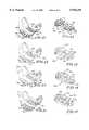
- FIG. 1is a perspective view of one embodiment of a bearing component in accordance with the present invention and showing an exterior and an opposite internal cavity defined by an interrupted articular face suitable for engaging a ball;
- FIG. 2is a cross-sectional view of the bearing component of FIG. 1 showing an interior of the bearing component including a mouth which defines the internal cavity and the interrupted articular face of the internal cavity having a generally hemispherical bearing surface and a plurality of intersecting grooves extending into the surface;
- FIG. 3is a cross-sectional view similar to FIG. 2 of another embodiment of a bearing component according to the present invention showing the interrupted articular face having a generally hemispherical bearing surface and a plurality of grooves extending into the surface substantially parallel to the mouth;
- FIG. 4is a cross-sectional view similar to FIG. 2 of another embodiment of a bearing component according to the present invention showing the interrupted articular face having a generally hemispherical bearing surface and a plurality of grooves extending into the surface substantially perpendicular to the mouth;
- FIG. 5is a cross-sectional view similar to FIG. 2 of another embodiment of a bearing component according to the present invention showing the interrupted articular face having a generally hemispherical bearing surface defined by a plurality of bearing platforms integral with the face and protruding into the internal cavity;
- FIG. 6is a cross-sectional view similar to FIG. 2 of another embodiment of a bearing component according to the present invention showing the interrupted articular face having a generally hemispherical bearing surface and a plurality of concave dimples extending into the bearing surface;
- FIG. 7is a cross-sectional view similar to FIG. 2 of another embodiment of a bearing component according to the present invention showing the interrupted articular face having a generally hemispherical bearing surface and a plurality of sockets extending into the bearing surface;
- FIG. 8is a cross-sectional view similar to FIG. 2 of another embodiment of a bearing component according to the present invention showing the interrupted articular face having a generally hemispherical bearing surface and a plurality of grooves extending into the surface and randomly weaving thereabout;
- FIG. 9is a perspective view of another embodiment of a bearing component in accordance with the present invention showing a ball attached to a stem and the ball including an interrupted articular face having a bearing surface and a plurality of intersecting groove extending into the surface;
- FIG. 10is a perspective view of a bearing component in accordance with the present invention showing a ball including an interrupted articular face having a plurality of concave dimples extending into the surface;
- FIG. 11shows an elevational view of another embodiment a bearing component in accordance with the present invention showing a patellar implant having an articular face interrupted by a plurality of bearing platforms with grooves extending therebetween;
- FIG. 12is a perspective view of another embodiment of the present invention showing a prosthetic bearing component for an extreme distal end of the femur, and the bearing component having interrupted condyles;
- FIG. 13is a perspective new similar to FIG. 12 of another embodiment of the present invention showing the interrupted condyles having a plurality of bearing platforms integral with the face and protruding therefrom;
- FIG. 14is a perspective view similar to FIG. 12 of another embodiment of the present invention showing the interrupted condyles having a plurality of concave dimples extending therein;
- FIG. 15is a perspective view similar to FIG. 12 of another embodiment of the present invention showing the interrupted condyles having a plurality of sockets extending therein;
- FIG. 16is a perspective view of yet another embodiment of the present invention showing a prosthetic bearing component for an extreme proximal end of the tibia and the bearing component showing two slightly concave interrupted bearing surfaces corresponding to the medial and labial condyles of the tibia;
- FIG. 17is a perspective view similar to FIG. 16 of another embodiment of the present invention showing the interrupted bearing surfaces having a plurality of bearing platforms integral with the surfaces and protruding therefrom;
- FIG. 18is a perspective view similar to FIG. 16 of another embodiment of the present invention showing the interrupted bearing surfaces having a plurality of concave dimples extending therein;
- FIG. 19is a perspective view similar to FIG. 16 of another embodiment of the present invention showing the interrupted bearing surfaces having a plurality of sockets extending therein.
- the present inventionis based upon the discovery that a bearing component having an articular face, interrupted by either recesses or protrusions, minimizes production of joint debris created by the interaction between the face and an accompanying joint face articulation member. This decrease is believed to be the result of the reduction in available surface area of articulation between the members, in comparison with traditional bearing components having smooth uninterrupted articulation faces.
- one bearing component in accordance with the present inventionallow physicians to utilize a large ball diameter for enhancement of joint stability while increasing lubrication and minimizing the production of undesirable joint debris when replacing a patient's ball-type joint with a prosthetic assembly.
- beneficially other bearing components in accordance with the present inventionallows a physician to increase lubrication and minimize the production of undesirable joint debris when replacing a patient's hip, shoulder, knee, elbow, ankle, wrist, or other joints with a prosthetic assembly.
- an illustrative bearing component 10having an exterior suitable for engagement with the acetabulum or use with a support cup (not shown).
- Acetabular cupsare mounted in the acetabulum using a variety of techniques, all well known in the orthopaedic field.
- the illustrative bearing component 10has an outer surface 16 which is generally hemispherical in shape to be received in a typical acetabular cup, it is contemplated that it may take on a variety of forms in order to cooperate with either the acetabulum or with the acetabular support cup.
- For an example of technique for mounting the bearing 10 in a support cupsee U.S. Pat. No.
- the bearing component 10may be mounted within the support cup, or even in the acetabulum however, using a variety of known attachment methods. See for example U.S. Pat. No. 4,904,265 to MacCollum, et al. and U.S. Pat. No. 5,002,577 to Bolesky et al.
- the bearing component 10illustratively comprises an interior 20 which forms an internal cavity 22 suitable for receiving a femoral head (not shown) therein and a one-piece interrupted articular face 24 for engagement and articulation with the femoral head.
- the term "one-piece”is used herein to mean that the articular face is itself shaped, molded, or formed to include said interruptions.
- the interrupted articular face 24 of the bearing component 10minimizes available surface area of articulation with the femoral head.
- the interior 20 of bearing component 10includes a mouth 26 extending about the internal cavity 22 and the circumference of the face 24. See FIG. 1. This mouth 26 of bearing component 10 defines a plane through which the femoral head enters the interior 20 of the bearing component 10 for engagement and articulation with the interrupted articular face 24.
- FIGS. 1-8The embodiments of one bearing component in accordance with the present invention that are illustrated in FIGS. 1-8 are formed for use with an acetabular prosthetic joint. However, as will be subsequently discussed, it is contemplated that specific patterns of interruptions within the articular face 24 may also be incorporated into a glenoid, patellar, femoral, humoral, tibial, ulnar, radial, wrist, and/or ankle component for a prosthetic joint assembly.
- the bearing component in accordance with the present inventioncan be made from any material that is biocompatible and which will undergo articulating movement with a corresponding natural or prosthetic member.
- the bearing componentcould be formed from a variety of metals, plastics, ceramics, or composite materials.
- plasticsa high density polyethylene may be used, although numerous types of plastics may be suitable for purposes of the invention so long as the material provides both strength and a low-friction articulation surface for the corresponding joint face.
- the bearing component in accordance with the present inventionis constructed in accordance with well known methods of manufacture. For example, it is understood that a metal shell can be cast, forged, or machined to include the interrupted articular face while ceramic, plastic, and composite materials suggest other well-known methods of manufacture.
- the interrupted articular face 24 of the interior 20includes a smooth spherically concave, generally hemispherical bearing surface 30 and a plurality of recess 32 formed within the surface 30. See FIGS. 1-4 and 6-8. It is understood that recesses may be formed and positioned in a variety of manners so long as the surface area of articulation is reduced from that of an uninterrupted smooth articular face (not shown) for an equivalently sized bearing component.
- the recesses 32may be formed as grooves 34, 36.
- the bearing surface 30is defined by a plurality of bearing platforms 31 integral with the face 24 and grooves 34 extending about bearing surface 30 and between the platforms 31 substantially parallel as shown by arrow 35, to the mouth 26.
- the interrupted articular face 24includes grooves 36 extending between the platforms 31 substantially perpendicular, as shown by arrow 37, relative to the mouth 26.
- grooves 34, 36illustratively cross one another at intersections 38.
- Grooves 34, 36are positioned in spaced-apart relation to one another about the bearing surface 30 of the interrupted articular face 24.
- grooves 34, 36may vary in number and positioning about the surface 30 of the interrupted articular face 24.
- the bearing component 110includes an interior 120 forming an internal cavity 122 and a mouth 126 extending about the cavity 122. Further, the interior 120 includes a one-piece interrupted articular face 124.
- the interrupted articular face 124has a bearing surface 130 defined by a plurality of bearing platforms 131 integral with the face 124 and a plurality of recesses 132 that extend into the surface 130.
- the recesses 132are formed as grooves 134 extending about the bearing surface 130 between the platforms 131 substantially parallel, as shown by arrow 135, to the mouth 126.
- the grooves 134are positioned in spaced-apart relation to one another about the bearing surface 130 of the face 124.
- a bearing component 150includes an interior 152 which forms an internal cavity 154 and a one-piece interrupted articular face 156. Additionally, the interior 152 includes a mouth 158 extending about the cavity 154.
- the interrupted articular face 156 of the interior 152includes a generally hemispherical bearing surface 160 defined by a plurality of bearing platforms 162 integral with the face 156 and recesses 164 formed as grooves 166 extending about the surface 160 between platforms 162 and substantially perpendicular, as shown by arrow 167 to the mouth 158.
- the grooves 166are illustratively positioned in spaced-apart relation to one another about the bearing surface 160 of the face 156.
- a bearing component 210in another embodiment of the present invention, shown in FIG. 5, includes an interior 212 that forms an internal cavity 214 and a one-piece interrupted articular face 216.
- the articular face 216is formed to include a generally hemispherical bearing surface 218 defined by a plurality of bearing platforms 220 integral with the face 216 and protruding into the cavity 214.
- the femoral head(not shown) will engage and articulate upon platforms 220 of the interrupted articular face 216 upon insertion into the cavity 214 of the bearing component 210.
- the platforms 220are positioned in spaced-apart relation to one another about the interrupted articular face 216. It is understood that while the platforms 220, as shown in FIG. 5, are generally convex in shape, they may take on a number of forms so long as a low friction articular face 216 is provided for the femoral head.
- a bearing component 250includes an interior 252 having an internal cavity 254 and a one-piece interrupted articular face 256.
- the interrupted articular face 256includes a smooth generally hemispherical bearing surface 260 defined by a plurality of bearing platforms 258 integral with the face 256.
- generally concave dimples 262extend into the face 256 between the platforms 258 to interrupt the surface 260.
- the dimples 262define a plurality of recesses 264 formed into the surface 260 of the interrupted articular face 256.
- the dimples 262are illustratively positioned in spaced-apart relation to one another about the bearing surface 260 of the interrupted articular face 256.
- the bearing component 310includes an interior 312 having an internal cavity 314 and a one-piece interrupted articular face 316.
- the articular face 316includes a smooth generally hemispherical bearing surface 318 and a plurality of sockets 320 defining recesses 322 extending into the surface 318.
- Each socket 320includes a conical-shaped mouth 324, a conical-shaped base 326, and a cylindrical side wall 328 extending between the mouth 324 and the base 326.
- the sockets 322are positioned in spaced-apart relation to one another about the bearing surface 318 of the articular face 316. However, it is contemplated that the number and positioning of the sockets 322 may be varied.
- the bearing component 350illustratively comprises an interior 352 which forms an internal cavity 354 suitable for receiving a femoral head (not shown) therein and a one-piece interrupted articular face 356 for engagement and articulation with the femoral head.
- the interrupted articular face 356 of the bearing component 350minimizes available surface area of articulation with the femoral head.
- the interior 352 of bearing component 350includes a mouth 358 extending about the circumference internal cavity 354. See FIG. 8.
- This mouth 358 of bearing component 350defines a plane through which the femoral head enters the interior 352 of the bearing component 350 for engagement and articulation with the interrupted articular face 356.
- the interrupted articular face 356 of the interior 352includes a smooth generally hemispherical bearing surface 360 defined by a plurality of bearing platforms 362 and a plurality of recesses 364 formed therein between the platforms 362.
- the bearing surface 360is integral with the face 356 and grooves 366 weave about bearing surface 360 and between the platforms 362.
- FIG. 9Another bearing component in accordance with the present invention is illustrated in FIG. 9.
- a ball head bearing component 410is provided for attachment to a neck 412.
- the neck 412is connected to a platform 414 which is then connected to an arcuate stem or shaft 416.
- the ball head component 410is insertable into the acetabular socket of the pelvis (not shown) once the prosthesis has been securely anchored in the femur.
- the ball head component 410is designed to work equally well with a natural acetabular socket or with any variety of artificial acetabular cups.
- the dimensions of the ball head 410can be easily varied to adapt to the particular bone structure of the patient or to the dimensions of the corresponding implanted prosthetic component.
- a ball head component 410is illustratively used as a hip joint prosthesis, it is contemplated that the ball head component, in accordance with the present invention could also be formed as a humeral head (not shown) for a shoulder joint prosthesis.
- a ball headsee U.S. Pat. No. 4,068,216 Townley et al., relevant portions of which are incorporated herein by reference.
- the ball head component 410comprises a one-piece interrupted articular socket-engaging face 418 which reduces surface area of articulation between the ball 410 and the corresponding socket (not shown).
- the interrupted articular socket-engaging face 418 of the ball head component 410includes a smooth spherically convex, generally hemispherical bearing surface 420 and a plurality of recess 422 formed within the surface 420.
- the recesses 422are formed as grooves 424, 426.
- the bearing surface 420is defined by a plurality of bearing platforms 428 integral with the face 418 and the grooves 424, 426 extend between the platforms 428.
- grooves 424extend in the direction shown by arrow 425 and grooves 426 extend as shown by arrow 427 between the platforms 428. It is understood that the grooves 424, 426 may extend about the bearing surface 420 in a variety of manners, so long as the surface area of articulation between the ball 410 and the corresponding socket is reduced.
- a ball head component 450includes a one-piece interrupted articular socket-engaging face 452 which reduces surface area of articulation between the ball 450 and the corresponding socket (not shown).
- the interrupted articular socket-engaging face 452 of the ball head component 450includes a smooth generally spherical bearing surface 454 and a plurality of recess 456 formed within the surface 454.
- the recesses 456are formed as generally concave dimples 458 and extend into the surface 454.
- the recesses 456are formed similarly to the dimples 262 shown in FIG. 6.
- a patellar joint bearing component 510comprises a bone facing surface 512 and a one-piece interrupted articular surface 514 opposite the bone facing surface 512. Additionally, a protuberance 516 extends from the bone facing surface 512.
- a patellar joint implantsee U.S. Pat. No. 4,964,867 to Boger, relevant portions of which are incorporated herein by reference.
- the interrupted articular surface 514 of the patellar joint implant 510minimizes available surface area of articulation with the femoral component of the knee (not shown).
- the interrupted articular face 514includes a smooth generally convex bearing surface 518 defined by a plurality of bearing platforms 520 integral with the face 514 and a plurality of recess 522 formed within the surface 518.
- the recesses 522are formed as grooves 524, 526 that extend between the platforms 520. It is understood that the surface 514 may be interrupted in a variety of manners, see for example FIGS. 2-8, so long as the surface area of articulation between the patellar implant 510 and the corresponding femoral component (not shown) is reduced.
- FIG. 12An additional embodiment of the bearing component in accordance with the present invention is illustrated in FIG. 12.
- a prosthetic femoral bearing component 550is provided which is adapted to replace the extreme distal portion of a femur (not shown).
- the femoral portion 550is formed to cooperate with either a natural femur or a femoral prosthetic device such as that illustrated in U.S. Pat. No. 4,822,366, relevant portions of which are incorporated herein by reference.
- the bearing component 550comprises on its surface two interrupted condyles or interrupted articular surfaces 552 that are configured to replace the condyles of the distal portion of the femur (not shown).
- the interrupted condyles 552minimize available surface area of articulation with either a natural tibia or a prosthetic tibial bearing component. While the illustrative bearing component is shown as being suitable for use with the tibia, it is contemplated that it may take on a form in order to cooperate with the radius and/or ulna or a radial and/or ulnar prosthesis. It is also understood that the bearing components illustrated in FIGS. 12-15 may also be used in conjunction with the extreme distal portion of the humerus.
- the interrupted condyles 552 of the bearing component 550include a smooth concave bearing surface 554 and a plurality of recesses 556 formed within the surface 554. Referring to FIG.
- the recesses 556are formed as grooves 558, 560.
- the bearing surface 554is defined by a plurality of bearing platforms 562 integral with the face 552 and the grooves 558, 560 extend between the platforms 562. It is understood, that the grooves 558, 560 may extend about the bearing surface 554 in a variety of manners, so long as the surface area of articulation between the bearing component 550 and the corresponding tibial bearing component (not shown) is reduced.
- an additional embodiment of the present inventionincludes a prosthetic femoral bearing component 610.
- the bearing component 610comprises on its surface two interrupted articular surfaces 612.
- the interrupted articular surfaces 612include a smooth surface 614 and a plurality of bearing platforms 616 integral with the surface 614.
- the platforms 616are positioned in spaced-apart relation to one another about the interrupted articular surface 612. It is understood that while the platforms 616, as shown in FIG. 13, are generally convex in shape, similar to the platforms 220 illustrated in FIG. 5, they may take on a number of forms so long as a low friction articular face is provided for the corresponding component.
- a femoral bearing component 650is provided which comprises two interrupted articular surfaces 652.
- Each articular surface 652includes a smooth bearing surface 656 that is defined by an interrupted bearing platform 654 for the accompanying articulating member.
- generally concave dimples 658extend into the surface 652 to interrupt the platform 654.
- the dimples 658define a plurality of recesses 660 formed into the surface 656 of the interrupted articular surface 652.
- the dimples 658are illustratively positioned in spaced-apart relation to one another about the bearing surface 652.
- a bearing component 710is provided which comprises two interrupted articular surfaces 712.
- Each articular surface 712is formed to include a plurality of sockets 716 defining recesses 718 that extend into the surface 714.
- Each socket 716is illustratively formed as the sockets 312 of FIG. 7.
- FIG. 16An additional embodiment of the present invention is illustrated in FIG. 16.
- a tibial bearing component 750is provided to replace the extreme proximal portion of the tibia (not shown).
- the tibial bearing component insert 750comprises two interrupted slightly concave bearing surfaces 752, 754 that are designed to replace the medial and lateral condyles of the tibia (not shown).
- the interrupted bearing surfaces 752, 754are adapted to support and mate with the articular surfaces on the femoral component (not shown).
- An interrupted articular face 756includes a smooth concave bearing surface 758 defined by a plurality of bearing platforms 760 integral with the face 756 and a plurality of recess 762 formed within the surface 758 between the platforms 760.
- the recesses 762are formed as grooves 764, 766.
- the grooves 764, 766illustratively extend between the platforms 760. It is understood, that the grooves 764, 766 may extend about the bearing surface 758 in a variety of manners, so long as the surface area of articulation between the femoral component 750 and the corresponding tibial bearing component (not shown) is reduced.
- FIG. 17An alternative embodiment of a tibial bearing component insert 810 of the present invention is illustrated in FIG. 17.
- the tibial bearing component insert 810includes two one-piece interrupted slightly concave articular surfaces 812, 814.
- the interrupted articular surfaces 812, 814include a concave bearing surface 816 and a plurality of bearing platforms 818 integral with the surface 816.
- the bearing platforms 218, 616are formed similarly to those shown in FIGS. 5 and 13 respectively.
- FIG. 18Yet another embodiment of a tibial bearing component insert 850 of the present invention is illustrated in FIG. 18.
- the tibial bearing component 850includes two one-piece interrupted slightly concave articular surfaces 852, 854.
- Each articular surface 852, 854is formed to include generally concave dimples 856 extending into the surface 852, 854 so that corresponding members engage and undergo articulating movement on the surfaces 852, 854.
- the dimples 856are formed similarly to the dimples 262, 456, and 658 shown in FIGS. 6, 10, and 14 respectively.
- FIG. 19A further embodiment of a tibial bearing component 910 of the present invention is shown in FIG. 19.
- the tibial bearing component 910includes a one-piece interrupted articular surfaces 912, 914.
- Each articular surface 912, 914is formed to include a plurality of sockets 916 defining recesses 918 that extend into the surface 912, 914.
- Each socket 916is formed as sockets 320, 716 shown in FIGS. 7 and 15 respectively.
- Bearing components in accordance with the present invention formed as acetabular sockets as shown in FIGS. 18enable the physician to use large ball diameters for joint stability while minimizing surface area of articulation.
- a bearing componentis manufactured for use as an acetabular socket to produce an internal diameter (hereinafter "I.D.") of 32 mm with the surface area of a 28 mm I.D. or 22 mm I.D. by interrupting the articular face with recesses.
- I.D.internal diameter
- Such a bearing componentwould have the joint stability of the 32 mm articulation and possibly the wear characteristics of the smaller I.D. It is believed that this decrease in surface area of articulation for the femoral head contributes the reduced production of joint debris.
- itdecreases the production of joint debris in conventional prosthetic assemblies by replacing the conventional bearing component with an improved bearing component in accordance with the present invention having an interrupted articular face.
- bearing components in accordance with the present inventionallow physicians to provide patients with prosthetic components with have reduced wear and greater stability within the body.
Landscapes
- Health & Medical Sciences (AREA)
- Orthopedic Medicine & Surgery (AREA)
- Heart & Thoracic Surgery (AREA)
- Vascular Medicine (AREA)
- Oral & Maxillofacial Surgery (AREA)
- Transplantation (AREA)
- Engineering & Computer Science (AREA)
- Biomedical Technology (AREA)
- Veterinary Medicine (AREA)
- Cardiology (AREA)
- Life Sciences & Earth Sciences (AREA)
- Animal Behavior & Ethology (AREA)
- General Health & Medical Sciences (AREA)
- Public Health (AREA)
- Physical Education & Sports Medicine (AREA)
- Prostheses (AREA)
Abstract
Description
The present invention relates to an improved component for a prosthesis assembly used in replacing a natural joint. More particularly, the present invention relates to a prosthetic component designed to include an interrupted articular face for minimizing surface area of articulation between itself and either a natural or prosthetic member.
It is known to provide a prosthetic joint assemblies for acetabulums, knees, ankles, shoulders, elbows, and wrists. Components of prosthetic joints such as that shown in U.S. Pat. No. 4,068,342 to Townley et al., provide a face having a continuous surface area of articulation for its corresponding member. While conventional prosthetic components beneficially provide a low-friction articular face for the surface of accompanying member, interaction between the articulating component and the member can produce joint debris. Such debris is expelled into the patient and may cause adverse reactions in the surrounding bodily tissue.
Attempts have been made to prevent joint debris produced by prosthesis joint assemblies from entering surrounding bodily tissue. See for example, U.S. Pat. No. 4,731,088 to Collier, where a flexible enclosure is applied to a prosthetic joint to isolate the joint debris from the surrounding tissue. What is needed is an improved bearing component for a prosthesis assembly which includes a face that is formed to minimize surface area of articulation for the engaging accompanying member and thus minimize the production of joint debris.
One object of the present invention is to provide an improved prosthetic component for use in a prosthesis which includes a surface that minimizes the production of joint debris produced from articulating movement of a corresponding member on said surface.
Another object of the present invention is to provide a bearing component for use in a prosthesis which includes an interior that forms an internal cavity suitable for receiving a ball therein, the cavity having an interrupted articular face for engaging the ball.
Still another object of the present invention is to provide a bearing component for use in a prosthesis which includes an interior that maximizes available ball distribution within said bearing component and minimizes the production of joint debris upon articulating movement of the ball.
Yet another object of the present invention is to provide an improved prosthetic component for use in a prothesis assembly which includes an interior that forms an internal cavity suitable for receiving a ball therein. The cavity being formed to enhance joint stability and reduce wear between the interior and the ball.
Another object of the present invention is to provide an improved prosthetic component for use in a prosthesis assembly which includes an interrupted articular face for engaging a corresponding articulating member.
According to one embodiment of the present invention a bearing component for a prosthesis of the ball-joint type, is provided. The bearing component provides a spherically concave bearing surface for receiving a ball, the surface being defined by a plurality of bearing platforms integral with said component. Thus, the bearing surface minimizes available surface area of articulation for the ball and the production of joint debris.
According to another aspect of the present invention a bearing component is provided for use with a ball. The bearing component has a generally hemispherical interior providing an internal cavity with an interrupted articular face. The interrupted articular face engages the ball and is interrupted by at least one recess extending into its bearing surface. In this specification and in the claims, the words "generally hemispherical" are intended to cover the spherical ranges conventionally used in acetabular and glenoid cup bearings including less than hemispherical and, in some cases, slightly more than hemispherical.
According to yet another aspect of the present invention a bearing component is provided for use with a ball. The bearing component comprises an interior having an internal cavity for receiving the ball therein. The cavity is defined by a one-piece articular face having a generally hemispherical bearing surface defined by at least one bearing platform extending into the internal cavity for engagement with the ball.
According to another embodiment of the present invention a ball component is provided for use with either a natural or prosthetic socket. The ball component comprises an interrupted articular socket-engaging face which effectively reduces surface area of articulation between the ball and the socket. The interrupted articular socket-engaging face rests against the socket and is interrupted by at least one recess extending into its surface. In this specification and in the claims, the words "ball component" are intended to cover prosthetic components for either the femoral or humeral head. Such ball components may be attached to an appropriate femoral or humoral stem.
According to another embodiment of the present invention a prosthetic patellar implant is provided for use with a natural or prosthetic knee. The patellar implant includes a patellum facing surface and a contoured interrupted surface opposite the patellum facing surface. The contoured interrupted surface engages either a natural or prosthetic distal end of a femur and is interrupted by a plurality of bearing platforms integral with said surface.
According to yet another embodiment of the present invention a prosthetic component is formed for replacing the extreme distal portion of the femur or the humorous and for attachment to either a prosthetic or natural femoral/humoral stem. The prosthetic component includes two interrupted condyles or articular surfaces that are configured to replace the smooth, uninterrupted condyles of the extreme distal portion. The condyles provide a convex interrupted bearing surface for engagement with medial and lateral condyles of a tibia or the condyle(s) of the radius and/or ulna. The interrupted articular surface of the prosthetic component is defined by a plurality of bearing platforms integral with the component.
According to yet another embodiment of the present invention, a prosthetic component is formed for replacing an extreme proximal portion of the tibia, radius, or ulna and in particular the medial and lateral condyles of the tibia or the condyle(s) of the radius and/or ulna. The prosthetic component is formed to include at least one slightly concave interrupted bearing surface. The interrupted bearing surfaces are formed to receive either a natural or prosthetic extreme distal portion of the femur or humorous, the surfaces being defined by a plurality of bearing platforms integral with the component. Thus, the bearing surface minimizes available surface area of articulation for the component and the production of joint debris.
The bearing components of the present invention are formed to reduce surface area of articulation between corresponding articulating bearing components. Because the articular face is interrupted by recesses and/or protrusions, the interrupted articulation surface will be maintained despite minimal wear that may occur at the point of contact between the bearing components. This reduction in surface area is intended to lead to a decrease in the production of joint debris which contributes to both wear debris incited osteolysis and eventually to failure of the prostheses assembly.
Other objects and features of the present invention will become apparent as this description progresses.
The detailed description particularly refers to the accompanying figures in which:
FIG. 1 is a perspective view of one embodiment of a bearing component in accordance with the present invention and showing an exterior and an opposite internal cavity defined by an interrupted articular face suitable for engaging a ball;
FIG. 2 is a cross-sectional view of the bearing component of FIG. 1 showing an interior of the bearing component including a mouth which defines the internal cavity and the interrupted articular face of the internal cavity having a generally hemispherical bearing surface and a plurality of intersecting grooves extending into the surface;
FIG. 3 is a cross-sectional view similar to FIG. 2 of another embodiment of a bearing component according to the present invention showing the interrupted articular face having a generally hemispherical bearing surface and a plurality of grooves extending into the surface substantially parallel to the mouth;
FIG. 4 is a cross-sectional view similar to FIG. 2 of another embodiment of a bearing component according to the present invention showing the interrupted articular face having a generally hemispherical bearing surface and a plurality of grooves extending into the surface substantially perpendicular to the mouth;
FIG. 5 is a cross-sectional view similar to FIG. 2 of another embodiment of a bearing component according to the present invention showing the interrupted articular face having a generally hemispherical bearing surface defined by a plurality of bearing platforms integral with the face and protruding into the internal cavity;
FIG. 6 is a cross-sectional view similar to FIG. 2 of another embodiment of a bearing component according to the present invention showing the interrupted articular face having a generally hemispherical bearing surface and a plurality of concave dimples extending into the bearing surface;
FIG. 7 is a cross-sectional view similar to FIG. 2 of another embodiment of a bearing component according to the present invention showing the interrupted articular face having a generally hemispherical bearing surface and a plurality of sockets extending into the bearing surface;
FIG. 8 is a cross-sectional view similar to FIG. 2 of another embodiment of a bearing component according to the present invention showing the interrupted articular face having a generally hemispherical bearing surface and a plurality of grooves extending into the surface and randomly weaving thereabout;
FIG. 9 is a perspective view of another embodiment of a bearing component in accordance with the present invention showing a ball attached to a stem and the ball including an interrupted articular face having a bearing surface and a plurality of intersecting groove extending into the surface;
FIG. 10 is a perspective view of a bearing component in accordance with the present invention showing a ball including an interrupted articular face having a plurality of concave dimples extending into the surface;
FIG. 11 shows an elevational view of another embodiment a bearing component in accordance with the present invention showing a patellar implant having an articular face interrupted by a plurality of bearing platforms with grooves extending therebetween;
FIG. 12 is a perspective view of another embodiment of the present invention showing a prosthetic bearing component for an extreme distal end of the femur, and the bearing component having interrupted condyles;
FIG. 13 is a perspective new similar to FIG. 12 of another embodiment of the present invention showing the interrupted condyles having a plurality of bearing platforms integral with the face and protruding therefrom;
FIG. 14 is a perspective view similar to FIG. 12 of another embodiment of the present invention showing the interrupted condyles having a plurality of concave dimples extending therein;
FIG. 15 is a perspective view similar to FIG. 12 of another embodiment of the present invention showing the interrupted condyles having a plurality of sockets extending therein;
FIG. 16 is a perspective view of yet another embodiment of the present invention showing a prosthetic bearing component for an extreme proximal end of the tibia and the bearing component showing two slightly concave interrupted bearing surfaces corresponding to the medial and labial condyles of the tibia;
FIG. 17 is a perspective view similar to FIG. 16 of another embodiment of the present invention showing the interrupted bearing surfaces having a plurality of bearing platforms integral with the surfaces and protruding therefrom;
FIG. 18 is a perspective view similar to FIG. 16 of another embodiment of the present invention showing the interrupted bearing surfaces having a plurality of concave dimples extending therein; and
FIG. 19 is a perspective view similar to FIG. 16 of another embodiment of the present invention showing the interrupted bearing surfaces having a plurality of sockets extending therein.
The present invention is based upon the discovery that a bearing component having an articular face, interrupted by either recesses or protrusions, minimizes production of joint debris created by the interaction between the face and an accompanying joint face articulation member. This decrease is believed to be the result of the reduction in available surface area of articulation between the members, in comparison with traditional bearing components having smooth uninterrupted articulation faces. Beneficially, one bearing component in accordance with the present invention allow physicians to utilize a large ball diameter for enhancement of joint stability while increasing lubrication and minimizing the production of undesirable joint debris when replacing a patient's ball-type joint with a prosthetic assembly. Further, beneficially other bearing components in accordance with the present invention allows a physician to increase lubrication and minimize the production of undesirable joint debris when replacing a patient's hip, shoulder, knee, elbow, ankle, wrist, or other joints with a prosthetic assembly.
Referring to FIG. 1, anillustrative bearing component 10 is shown having an exterior suitable for engagement with the acetabulum or use with a support cup (not shown). Acetabular cups are mounted in the acetabulum using a variety of techniques, all well known in the orthopaedic field. While theillustrative bearing component 10 has anouter surface 16 which is generally hemispherical in shape to be received in a typical acetabular cup, it is contemplated that it may take on a variety of forms in order to cooperate with either the acetabulum or with the acetabular support cup. For an example of technique for mounting the bearing 10 in a support cup, see U.S. Pat. No. 5,049,158 to Engelhardt et al., relevant portions of which are incorporated herein by reference. The bearingcomponent 10 may be mounted within the support cup, or even in the acetabulum however, using a variety of known attachment methods. See for example U.S. Pat. No. 4,904,265 to MacCollum, et al. and U.S. Pat. No. 5,002,577 to Bolesky et al.
Referring again to FIG. 1, the bearingcomponent 10 illustratively comprises an interior 20 which forms aninternal cavity 22 suitable for receiving a femoral head (not shown) therein and a one-piece interruptedarticular face 24 for engagement and articulation with the femoral head. The term "one-piece" is used herein to mean that the articular face is itself shaped, molded, or formed to include said interruptions. The interruptedarticular face 24 of the bearingcomponent 10 minimizes available surface area of articulation with the femoral head. Illustratively, theinterior 20 of bearingcomponent 10 includes amouth 26 extending about theinternal cavity 22 and the circumference of theface 24. See FIG. 1. Thismouth 26 of bearingcomponent 10 defines a plane through which the femoral head enters the interior 20 of the bearingcomponent 10 for engagement and articulation with the interruptedarticular face 24.
The embodiments of one bearing component in accordance with the present invention that are illustrated in FIGS. 1-8 are formed for use with an acetabular prosthetic joint. However, as will be subsequently discussed, it is contemplated that specific patterns of interruptions within thearticular face 24 may also be incorporated into a glenoid, patellar, femoral, humoral, tibial, ulnar, radial, wrist, and/or ankle component for a prosthetic joint assembly.
It is understood that the bearing component in accordance with the present invention can be made from any material that is biocompatible and which will undergo articulating movement with a corresponding natural or prosthetic member. For example, the bearing component could be formed from a variety of metals, plastics, ceramics, or composite materials. In the event that plastics are chosen, a high density polyethylene may be used, although numerous types of plastics may be suitable for purposes of the invention so long as the material provides both strength and a low-friction articulation surface for the corresponding joint face. Further, the bearing component in accordance with the present invention is constructed in accordance with well known methods of manufacture. For example, it is understood that a metal shell can be cast, forged, or machined to include the interrupted articular face while ceramic, plastic, and composite materials suggest other well-known methods of manufacture.
In one embodiment of the bearing component, the interruptedarticular face 24 of the interior 20 includes a smooth spherically concave, generallyhemispherical bearing surface 30 and a plurality ofrecess 32 formed within thesurface 30. See FIGS. 1-4 and 6-8. It is understood that recesses may be formed and positioned in a variety of manners so long as the surface area of articulation is reduced from that of an uninterrupted smooth articular face (not shown) for an equivalently sized bearing component.
As best shown in FIG. 2, therecesses 32 may be formed asgrooves surface 30 is defined by a plurality of bearingplatforms 31 integral with theface 24 andgrooves 34 extending about bearingsurface 30 and between theplatforms 31 substantially parallel as shown byarrow 35, to themouth 26. Additionally, the interruptedarticular face 24 includesgrooves 36 extending between theplatforms 31 substantially perpendicular, as shown byarrow 37, relative to themouth 26. Thus,grooves intersections 38.Grooves surface 30 of the interruptedarticular face 24. However, it is contemplated thatgrooves surface 30 of the interruptedarticular face 24.
Another embodiment of the bearing component is illustrated in FIG. 3. Thebearing component 110 includes an interior 120 forming aninternal cavity 122 and amouth 126 extending about thecavity 122. Further, theinterior 120 includes a one-piece interruptedarticular face 124. The interruptedarticular face 124 has abearing surface 130 defined by a plurality of bearingplatforms 131 integral with theface 124 and a plurality ofrecesses 132 that extend into thesurface 130. Therecesses 132 are formed asgrooves 134 extending about the bearingsurface 130 between theplatforms 131 substantially parallel, as shown byarrow 135, to themouth 126. Illustratively, thegrooves 134 are positioned in spaced-apart relation to one another about the bearingsurface 130 of theface 124.
Yet another embodiment of the present invention is illustrated in FIG. 4. Abearing component 150 includes an interior 152 which forms aninternal cavity 154 and a one-piece interruptedarticular face 156. Additionally, theinterior 152 includes amouth 158 extending about thecavity 154. The interruptedarticular face 156 of the interior 152 includes a generallyhemispherical bearing surface 160 defined by a plurality of bearingplatforms 162 integral with theface 156 and recesses 164 formed asgrooves 166 extending about thesurface 160 betweenplatforms 162 and substantially perpendicular, as shown byarrow 167 to themouth 158. Moreover, thegrooves 166 are illustratively positioned in spaced-apart relation to one another about the bearingsurface 160 of theface 156.
In another embodiment of the present invention, shown in FIG. 5, abearing component 210 includes an interior 212 that forms aninternal cavity 214 and a one-piece interruptedarticular face 216. Illustratively, thearticular face 216 is formed to include a generallyhemispherical bearing surface 218 defined by a plurality of bearingplatforms 220 integral with theface 216 and protruding into thecavity 214. Thus, the femoral head (not shown) will engage and articulate uponplatforms 220 of the interruptedarticular face 216 upon insertion into thecavity 214 of thebearing component 210. Illustratively, theplatforms 220 are positioned in spaced-apart relation to one another about the interruptedarticular face 216. It is understood that while theplatforms 220, as shown in FIG. 5, are generally convex in shape, they may take on a number of forms so long as a low frictionarticular face 216 is provided for the femoral head.
Further, another embodiment of the present invention is illustrated in FIG. 6. A bearing component 250 includes an interior 252 having aninternal cavity 254 and a one-piece interruptedarticular face 256. The interruptedarticular face 256 includes a smooth generallyhemispherical bearing surface 260 defined by a plurality of bearingplatforms 258 integral with theface 256. Moreover, generallyconcave dimples 262 extend into theface 256 between theplatforms 258 to interrupt thesurface 260. Thedimples 262 define a plurality ofrecesses 264 formed into thesurface 260 of the interruptedarticular face 256. Moreover thedimples 262 are illustratively positioned in spaced-apart relation to one another about the bearingsurface 260 of the interruptedarticular face 256.
Another embodiment of the present invention is illustrated in FIG. 7. Thebearing component 310 includes an interior 312 having aninternal cavity 314 and a one-piece interruptedarticular face 316. Thearticular face 316 includes a smooth generallyhemispherical bearing surface 318 and a plurality ofsockets 320 definingrecesses 322 extending into thesurface 318. Eachsocket 320 includes a conical-shapedmouth 324, a conical-shapedbase 326, and acylindrical side wall 328 extending between themouth 324 and thebase 326. Illustratively, thesockets 322 are positioned in spaced-apart relation to one another about the bearingsurface 318 of thearticular face 316. However, it is contemplated that the number and positioning of thesockets 322 may be varied.
Another bearing component in accordance with the present invention is illustrated in FIG. 8. Thebearing component 350 illustratively comprises an interior 352 which forms aninternal cavity 354 suitable for receiving a femoral head (not shown) therein and a one-piece interruptedarticular face 356 for engagement and articulation with the femoral head. The interruptedarticular face 356 of thebearing component 350 minimizes available surface area of articulation with the femoral head.
Illustratively, theinterior 352 of bearingcomponent 350 includes amouth 358 extending about the circumferenceinternal cavity 354. See FIG. 8. Thismouth 358 of bearingcomponent 350 defines a plane through which the femoral head enters theinterior 352 of thebearing component 350 for engagement and articulation with the interruptedarticular face 356. The interruptedarticular face 356 of the interior 352 includes a smooth generallyhemispherical bearing surface 360 defined by a plurality of bearingplatforms 362 and a plurality of recesses 364 formed therein between theplatforms 362. Referring to FIG. 8, the bearingsurface 360 is integral with theface 356 andgrooves 366 weave about bearingsurface 360 and between theplatforms 362.
Another bearing component in accordance with the present invention is illustrated in FIG. 9. A ballhead bearing component 410 is provided for attachment to aneck 412. Theneck 412 is connected to aplatform 414 which is then connected to an arcuate stem orshaft 416. Theball head component 410 is insertable into the acetabular socket of the pelvis (not shown) once the prosthesis has been securely anchored in the femur. Theball head component 410 is designed to work equally well with a natural acetabular socket or with any variety of artificial acetabular cups. As with all other embodiments of the present invention, the dimensions of theball head 410 can be easily varied to adapt to the particular bone structure of the patient or to the dimensions of the corresponding implanted prosthetic component. While aball head component 410 is illustratively used as a hip joint prosthesis, it is contemplated that the ball head component, in accordance with the present invention could also be formed as a humeral head (not shown) for a shoulder joint prosthesis. For further description of a ball head see U.S. Pat. No. 4,068,216 Townley et al., relevant portions of which are incorporated herein by reference.
Theball head component 410 comprises a one-piece interrupted articular socket-engagingface 418 which reduces surface area of articulation between theball 410 and the corresponding socket (not shown). The interrupted articular socket-engagingface 418 of theball head component 410 includes a smooth spherically convex, generallyhemispherical bearing surface 420 and a plurality ofrecess 422 formed within thesurface 420. Illustratively, therecesses 422 are formed asgrooves surface 420 is defined by a plurality of bearingplatforms 428 integral with theface 418 and thegrooves platforms 428. Preferablygrooves 424 extend in the direction shown byarrow 425 andgrooves 426 extend as shown byarrow 427 between theplatforms 428. It is understood that thegrooves surface 420 in a variety of manners, so long as the surface area of articulation between theball 410 and the corresponding socket is reduced.
Another embodiment of the bearing component in accordance with the present invention is illustrated in FIG. 10. Aball head component 450 includes a one-piece interrupted articular socket-engagingface 452 which reduces surface area of articulation between theball 450 and the corresponding socket (not shown). The interrupted articular socket-engagingface 452 of theball head component 450 includes a smooth generallyspherical bearing surface 454 and a plurality ofrecess 456 formed within thesurface 454. Illustratively, therecesses 456 are formed as generallyconcave dimples 458 and extend into thesurface 454. Illustratively, therecesses 456 are formed similarly to thedimples 262 shown in FIG. 6.
Another embodiment of the bearing component in accordance with the present invention is illustrated in FIG. 11. A patellarjoint bearing component 510 comprises abone facing surface 512 and a one-piece interruptedarticular surface 514 opposite thebone facing surface 512. Additionally, aprotuberance 516 extends from thebone facing surface 512. For further description of a patellar joint implant see U.S. Pat. No. 4,964,867 to Boger, relevant portions of which are incorporated herein by reference. The interruptedarticular surface 514 of the patellarjoint implant 510 minimizes available surface area of articulation with the femoral component of the knee (not shown). The interruptedarticular face 514 includes a smooth generallyconvex bearing surface 518 defined by a plurality of bearingplatforms 520 integral with theface 514 and a plurality ofrecess 522 formed within thesurface 518. Illustratively therecesses 522 are formed asgrooves platforms 520. It is understood that thesurface 514 may be interrupted in a variety of manners, see for example FIGS. 2-8, so long as the surface area of articulation between thepatellar implant 510 and the corresponding femoral component (not shown) is reduced.
An additional embodiment of the bearing component in accordance with the present invention is illustrated in FIG. 12. A prostheticfemoral bearing component 550 is provided which is adapted to replace the extreme distal portion of a femur (not shown). Thefemoral portion 550 is formed to cooperate with either a natural femur or a femoral prosthetic device such as that illustrated in U.S. Pat. No. 4,822,366, relevant portions of which are incorporated herein by reference. Thebearing component 550 comprises on its surface two interrupted condyles or interruptedarticular surfaces 552 that are configured to replace the condyles of the distal portion of the femur (not shown). The interruptedcondyles 552 minimize available surface area of articulation with either a natural tibia or a prosthetic tibial bearing component. While the illustrative bearing component is shown as being suitable for use with the tibia, it is contemplated that it may take on a form in order to cooperate with the radius and/or ulna or a radial and/or ulnar prosthesis. It is also understood that the bearing components illustrated in FIGS. 12-15 may also be used in conjunction with the extreme distal portion of the humerus. The interruptedcondyles 552 of thebearing component 550 include a smoothconcave bearing surface 554 and a plurality ofrecesses 556 formed within thesurface 554. Referring to FIG. 12, therecesses 556 are formed asgrooves surface 554 is defined by a plurality of bearingplatforms 562 integral with theface 552 and thegrooves platforms 562. It is understood, that thegrooves surface 554 in a variety of manners, so long as the surface area of articulation between the bearingcomponent 550 and the corresponding tibial bearing component (not shown) is reduced.
Referring now to FIG. 13, an additional embodiment of the present invention includes a prostheticfemoral bearing component 610. Thebearing component 610 comprises on its surface two interruptedarticular surfaces 612. The interruptedarticular surfaces 612 include asmooth surface 614 and a plurality of bearingplatforms 616 integral with thesurface 614. Illustratively, theplatforms 616 are positioned in spaced-apart relation to one another about the interruptedarticular surface 612. It is understood that while theplatforms 616, as shown in FIG. 13, are generally convex in shape, similar to theplatforms 220 illustrated in FIG. 5, they may take on a number of forms so long as a low friction articular face is provided for the corresponding component.
An additional embodiment of the present invention is illustrated in FIG. 14. Afemoral bearing component 650 is provided which comprises two interruptedarticular surfaces 652. Eacharticular surface 652 includes asmooth bearing surface 656 that is defined by an interruptedbearing platform 654 for the accompanying articulating member. Moreover, generallyconcave dimples 658 extend into thesurface 652 to interrupt theplatform 654. Thedimples 658 define a plurality ofrecesses 660 formed into thesurface 656 of the interruptedarticular surface 652. Moreover thedimples 658 are illustratively positioned in spaced-apart relation to one another about the bearingsurface 652.
Further, as illustrated in FIG. 15, an additional embodiment of the present invention is provided. Abearing component 710 is provided which comprises two interruptedarticular surfaces 712. Eacharticular surface 712 is formed to include a plurality ofsockets 716 definingrecesses 718 that extend into the surface 714. Eachsocket 716 is illustratively formed as thesockets 312 of FIG. 7.
An additional embodiment of the present invention is illustrated in FIG. 16. Atibial bearing component 750 is provided to replace the extreme proximal portion of the tibia (not shown). The tibialbearing component insert 750 comprises two interrupted slightly concave bearing surfaces 752, 754 that are designed to replace the medial and lateral condyles of the tibia (not shown). The interrupted bearing surfaces 752, 754 are adapted to support and mate with the articular surfaces on the femoral component (not shown). For a further description of the articulating movement of a prosthetic tibialbearing component insert 750 suitable for use with the present invention, see U.S. Pat. No. 4,822,366, to Bolesky relevant portions of which are incorporated herein by reference. It is further contemplated that components such as those illustrated in FIGS. 16-19 could be adapted for use with the extreme proximal portion of the radius and/or ulna.
An interruptedarticular face 756 includes a smoothconcave bearing surface 758 defined by a plurality of bearingplatforms 760 integral with theface 756 and a plurality ofrecess 762 formed within thesurface 758 between theplatforms 760. Illustratively, therecesses 762 are formed asgrooves grooves platforms 760. It is understood, that thegrooves surface 758 in a variety of manners, so long as the surface area of articulation between thefemoral component 750 and the corresponding tibial bearing component (not shown) is reduced.
An alternative embodiment of a tibialbearing component insert 810 of the present invention is illustrated in FIG. 17. The tibialbearing component insert 810 includes two one-piece interrupted slightly concavearticular surfaces articular surfaces concave bearing surface 816 and a plurality of bearingplatforms 818 integral with thesurface 816. Illustratively, the bearingplatforms
Yet another embodiment of a tibialbearing component insert 850 of the present invention is illustrated in FIG. 18. Thetibial bearing component 850 includes two one-piece interrupted slightly concavearticular surfaces articular surface concave dimples 856 extending into thesurface surfaces dimples 856 are formed similarly to thedimples
A further embodiment of atibial bearing component 910 of the present invention is shown in FIG. 19. thetibial bearing component 910 includes a one-piece interruptedarticular surfaces articular surface sockets 916 definingrecesses 918 that extend into thesurface socket 916 is formed assockets
Bearing components in accordance with the present invention formed as acetabular sockets as shown in FIGS. 18 enable the physician to use large ball diameters for joint stability while minimizing surface area of articulation. For example, a bearing component is manufactured for use as an acetabular socket to produce an internal diameter (hereinafter "I.D.") of 32 mm with the surface area of a 28 mm I.D. or 22 mm I.D. by interrupting the articular face with recesses. Such a bearing component would have the joint stability of the 32 mm articulation and possibly the wear characteristics of the smaller I.D. It is believed that this decrease in surface area of articulation for the femoral head contributes the reduced production of joint debris. Thus, it decreases the production of joint debris in conventional prosthetic assemblies by replacing the conventional bearing component with an improved bearing component in accordance with the present invention having an interrupted articular face.
Further, bearing components in accordance with the present invention allow physicians to provide patients with prosthetic components with have reduced wear and greater stability within the body.
Although the invention has been described in detail with reference to certain preferred embodiments, variations and modifications exist within the scope and spirit of the invention as described and defined in the following claims.
Claims (26)
1. A bearing component for a prosthesis, said bearing component comprising an interrupted articular face constructed of a plastics material suitable for mating with a corresponding joint face, the interrupted articular face includes a mouth extending about a circumference of the face, at least one recess intersecting the mouth and a bearing surface being defined by at least one bearing platform integral with the articular face and suitable to engage the corresponding joint face and to permit movement therewith.
2. The bearing component of claim 1, wherein the recess is formed as a groove extending about the bearing surface and through the bearing platform.
3. The bearing component of claim 1, wherein the interrupted articular face includes a plurality of recesses formed as grooves.
4. The bearing component of claim 3, wherein the grooves are positioned in spaced-apart relation to one another about the bearing surface.
5. The bearing component of claim 3, wherein the bearing surface is further defined by generally annular grooves that are positioned in an intersecting relationship relative to grooves about the bearing surface.
6. The bearing component of claim 1, wherein the recess is formed as a generally concave dimple in the bearing surface.
7. The bearing component of claim 6, wherein the interrupted articular face is formed to include a plurality of recesses formed as dimples, and the dimples are positioned in spaced-apart relation to one another about the bearing surface.
8. The bearing component of claim 1, wherein the recess is formed as a socket in the bearing surface and the socket includes a conical-shaped mouth, a conical-shaped base, and a cylindrical side wall extending between the mouth and the base.
9. The bearing component of claim 1, wherein said bearing surface being defined by a plurality of bearing platforms positioned in spaced-apart relation to one another about said interrupted articular face.
10. A bearing component for a prosthesis of the ball-joint type, said bearing component comprising an interior providing an internal cavity suitable for receiving a ball, said cavity being defined by a spherically concave interrupted articular face integral with the bearing component and suitable for engaging the ball, said bearing component further a mouth extending comprising about the internal cavity and the circumference of said interrupted articular face, said interrupted articular face being constructed of a plastics material and including at least one recess intersecting the mouth.
11. The bearing component of claim 10, wherein the interrupted articular face is formed to include a smooth generally hemispherical bearing surface wherein said at least one recess extending into the bearing surface.
12. The bearing component of claim 11, wherein the interior includes an annular lip extending about the circumference of the mouth and at least one groove extending about said bearing surface generally parallel to the lip.
13. The bearing component of claim 12, wherein the interrupted articular face is formed to include a plurality of grooves positioned in spaced-apart relation to one another about the bearing surface of the interrupted articular face.
14. The bearing component of claim 11, wherein said least one recess is formed as a groove extending generally perpendicular to an annular lip extending about the circumference of the mouth.
15. The bearing component of claim 14, wherein the interior includes at least one groove extending about the surface generally parallel to the lip and intersects at least one groove extending about said bearing surface generally perpendicular to the lip.
16. The bearing component of claim 14, wherein a plurality of grooves are formed to extend generally perpendicular to the lip in spaced-apart relation to one another about the bearing surface of the interrupted articular face.
17. The bearing component of claim 11, wherein the interior includes an annular lip extending about the circumference of the mouth and said at least one recess is formed as a groove positioned generally perpendicular to said lip.
18. The bearing component of claim 17, wherein a plurality of grooves are positioned in spaced-apart relation to one another about the bearing surface of the interrupted articular face.
19. The bearing component of claim 11, wherein the interrupted articular face includes generally concave dimples in the smooth bearing surface of the articular face and the dimples are formed to define the recesses within the bearing surface.
20. The bearing component of claim 19, wherein the dimples are positioned in spaced-apart relation to one another about the bearing surface of the articular face.
21. The bearing component of claim 11, wherein the interrupted articular face includes at least one socket extending into the bearing surface, each socket includes a conical-shaped mouth, a conical-shaped base, and a cylindrical side wall extending between the mouth and the base and the sockets are formed to define the recesses within the bearing surface.
22. A bearing component for a prosthesis of the ball-joint type, said bearing component comprising an interior providing an internal cavity suitable for receiving a ball, said cavity being defined by a spherically concave interrupted articular bearing face integral with the bearing component and suitable for engaging the ball, and a mouth extending about the internal cavity and the circumference of the face, said interrupted articular bearing face being constructed of a plastics material, and including a smooth generally hemispherical surface intersecting the mouth and including bearing platforms protruding into the internal cavity.
23. The bearing component of claim 22, wherein the bearing platforms are positioned in spaced-apart relation to one another about the smooth surface of the interrupted articular bearing face.
24. A prosthetic component assembly adapted for use in an acetabular cup fixed to the acetabulum, the assembly comprising
a femoral element including a ball, and
an acetabular bearing including an outer surface configured to be received in the acetabular cup and an interrupted articular face constructed of a plastics material adapted to mate with the ball of the femoral element, the interrupted articular face including a mouth extending about a circumference of said articular face and a bearing surface being defined by at least one bearing platform integral with the articular face and adapted to engage the corresponding ball to maximize available ball distribution and permit articulating movement of the ball within the bearing and at least one recess intersecting the mouth.
25. The prosthetic component of claim 24, wherein the recess is formed as a groove extending about the bearing surface and through the bearing platform.
26. The prosthetic component of claim 24, wherein the articular face includes a plurality of bearing platforms positioned to lie in spaced-apart relation to one another about the bearing surface.
Priority Applications (1)
| Application Number | Priority Date | Filing Date | Title |
|---|---|---|---|
| US08/656,780US5916269A (en) | 1996-06-03 | 1996-06-03 | Wear reduced acetabular component |
Applications Claiming Priority (1)
| Application Number | Priority Date | Filing Date | Title |
|---|---|---|---|
| US08/656,780US5916269A (en) | 1996-06-03 | 1996-06-03 | Wear reduced acetabular component |
Publications (1)
| Publication Number | Publication Date |
|---|---|
| US5916269Atrue US5916269A (en) | 1999-06-29 |
Family
ID=24634532
Family Applications (1)
| Application Number | Title | Priority Date | Filing Date |
|---|---|---|---|
| US08/656,780Expired - LifetimeUS5916269A (en) | 1996-06-03 | 1996-06-03 | Wear reduced acetabular component |
Country Status (1)
| Country | Link |
|---|---|
| US (1) | US5916269A (en) |
Cited By (85)
| Publication number | Priority date | Publication date | Assignee | Title |
|---|---|---|---|---|
| US20030019106A1 (en)* | 2001-04-22 | 2003-01-30 | Diamicron, Inc. | Methods for making bearings, races and components thereof having diamond and other superhard surfaces |
| EP1321113A2 (en) | 2001-12-19 | 2003-06-25 | Depuy Orthopaedics, Inc. | Prosthetic joints having reduced area bearing surfaces and application thereof to a range of sizes of prosthetic joints |
| US6651672B2 (en) | 1993-02-22 | 2003-11-25 | Heartport, Inc. | Devices for less-invasive intracardiac interventions |
| US20040030402A1 (en)* | 2002-08-08 | 2004-02-12 | Uri Arnin | Elastomeric covers for orthopedic implants |
| US20040111159A1 (en)* | 2000-01-30 | 2004-06-10 | Diamicron, Inc. | Modular bearing surfaces in prosthetic joints |
| US6770078B2 (en) | 2000-01-14 | 2004-08-03 | Peter M. Bonutti | Movable knee implant and methods therefor |
| US20040199260A1 (en)* | 2000-01-30 | 2004-10-07 | Pope Bill J. | Prosthetic joint component having at least one sintered polycrystalline diamond compact articulation surface and substrate surface topographical features in said polycrystalline diamond compact |
| WO2004084772A1 (en)* | 2003-03-25 | 2004-10-07 | Ceramtec Ag | Polylock insert for an artificial hip joint |
| EP1475057A1 (en)* | 2003-04-14 | 2004-11-10 | ESKA Implants GmbH & Co. | Joint ball head |
| USD503801S1 (en)* | 2004-04-05 | 2005-04-05 | Roger P. Jackson | Interbody spacer for spinal implantation |
| FR2860427A1 (en)* | 2003-10-03 | 2005-04-08 | Philippe Valenti | HUMERAL INSERT FOR AN INVERSE SHOULDER PROSTHESIS. |
| US20050087915A1 (en)* | 1999-12-08 | 2005-04-28 | Diamicron, Inc. | Carbides as a substrate material in prosthetic joints |
| US20050110187A1 (en)* | 1999-12-08 | 2005-05-26 | Diamicron, Inc. | Use of Ti and Nb cemented in TiC in prosthetic joints |
| US20050133277A1 (en)* | 2003-08-28 | 2005-06-23 | Diamicron, Inc. | Superhard mill cutters and related methods |
| US20050203630A1 (en)* | 2000-01-30 | 2005-09-15 | Pope Bill J. | Prosthetic knee joint having at least one diamond articulation surface |
| US20060149386A1 (en)* | 2001-11-07 | 2006-07-06 | Clarke Michael T | Joint prostheses |
| US7104996B2 (en) | 2000-01-14 | 2006-09-12 | Marctec. Llc | Method of performing surgery |
| US20060263233A1 (en)* | 1999-12-08 | 2006-11-23 | Diamicron, Inc. | Use of a metal and Sn as a solvent material for the bulk crystallization and sintering of diamond to produce biocompatbile biomedical devices |
| US20070140784A1 (en)* | 2003-12-25 | 2007-06-21 | Kabushiki Kaisha Somic Ishikawa | Ball joint and bearing seat thereof |
| US7255712B1 (en) | 1997-04-15 | 2007-08-14 | Active Implants Corporation | Bone growth promoting implant |
| WO2007069250A3 (en)* | 2005-12-14 | 2007-11-01 | Presrv Ltd | Faceted long bone head prosthesis |
| US20070270975A1 (en)* | 2006-05-12 | 2007-11-22 | Finsbury (Development) Limited | Prosthesis |
| WO2008015288A1 (en)* | 2006-08-04 | 2008-02-07 | Ceramtec Ag | Structured surface of a ball head or a socket insert of an artificial hip joint for avoiding running dry |
| US20080154369A1 (en)* | 2006-11-07 | 2008-06-26 | Barr George A | Medical implants |
| EP1972308A1 (en)* | 2007-03-21 | 2008-09-24 | ESKA Implants GmbH & Co. KG | Ball socket or cap implant for an artificial hip joint. |
| US7445639B2 (en) | 2001-02-23 | 2008-11-04 | Biomet Manufacturing Corp. | Knee joint prosthesis |
| US20090046967A1 (en)* | 2001-04-22 | 2009-02-19 | Pope Bill J | Bearings, races and components thereof having diamond and other superhard surfaces |
| US7497874B1 (en) | 2001-02-23 | 2009-03-03 | Biomet Manufacturing Corp. | Knee joint prosthesis |
| US7510557B1 (en) | 2000-01-14 | 2009-03-31 | Bonutti Research Inc. | Cutting guide |
| US20090125108A1 (en)* | 2007-11-08 | 2009-05-14 | Linares Medical Devices, Llc | Artificial knee implant including liquid ballast supporting / rotating surfaces and incorporating flexible multi-material and natural lubricant retaining matrix applied to a joint surface |
| US7572295B2 (en) | 2001-12-04 | 2009-08-11 | Active Implants Corporation | Cushion bearing implants for load bearing applications |
| US20090248166A1 (en)* | 2008-03-26 | 2009-10-01 | Linares Miguel A | Joint construction, such as for use by athletes |
| US20090263643A1 (en)* | 2005-04-07 | 2009-10-22 | Gardinier Clayton F | Use of sn and pore size control to improve biocompatibility in polycrystalline diamond compacts |
| US20100025898A1 (en)* | 2000-01-30 | 2010-02-04 | Pope Bill J | USE OF Ti AND Nb CEMENTED TiC IN PROSTHETIC JOINTS |
| US20100042215A1 (en)* | 2008-08-13 | 2010-02-18 | Stalcup Gregory C | Orthopaedic implant |
| US20100042214A1 (en)* | 2008-08-13 | 2010-02-18 | Nebosky Paul S | Drug delivery implants |
| US20100042213A1 (en)* | 2008-08-13 | 2010-02-18 | Nebosky Paul S | Drug delivery implants |
| US20100042226A1 (en)* | 2008-08-13 | 2010-02-18 | Nebosky Paul S | Orthopaedic implant with spatially varying porosity |
| US20100042167A1 (en)* | 2008-08-13 | 2010-02-18 | Nebosky Paul S | Orthopaedic screws |
| US7708741B1 (en) | 2001-08-28 | 2010-05-04 | Marctec, Llc | Method of preparing bones for knee replacement surgery |
| US20100161064A1 (en)* | 2006-11-07 | 2010-06-24 | Kellar Franz W | Prosthetic joint |
| US7758653B2 (en) | 2002-05-23 | 2010-07-20 | Active Implants Corporation | Implants |
| US20100198353A1 (en)* | 2000-01-30 | 2010-08-05 | Pope Bill J | USE OF Ti and Nb CEMENTED IN TiC IN PROSTHETIC JOINTS |
| US20100222872A1 (en)* | 2006-05-02 | 2010-09-02 | Advanced Cardiovascular Systems, Inc. | Methods, Compositions and Devices for Treating Lesioned Sites Using Bioabsorbable Carriers |
| US20100222892A1 (en)* | 2007-11-08 | 2010-09-02 | Linares Medical Devices, Llc | Joint assembly incorporating undercut surface design to entrap accumulating wear debris from plastic joint assembly |
| US20100262250A1 (en)* | 2006-11-07 | 2010-10-14 | Kellar Franz W | Prosthetic ball-and-socket joint |
| US20110035012A1 (en)* | 2008-02-25 | 2011-02-10 | Linares Medical Devices, Llc | Artificial wear resistant plug for mounting to existing joint bone |
| US20110087333A1 (en)* | 2006-11-07 | 2011-04-14 | Kellar Franz W | Prosthetic knee joint |
| JP2011087712A (en)* | 2009-10-21 | 2011-05-06 | Univ Of Tokyo | Liner for artificial hip joint and artificial hip joint using the same |
| US7959635B1 (en) | 2000-01-14 | 2011-06-14 | Marctec, Llc. | Limited incision total joint replacement methods |
| US20110146348A1 (en)* | 2009-06-26 | 2011-06-23 | Harding David P | Thick sintered polycrystalline diamond and sintered jewelry |
| US20110166671A1 (en)* | 2006-11-07 | 2011-07-07 | Kellar Franz W | Prosthetic joint |
| US20110166667A1 (en)* | 2006-11-07 | 2011-07-07 | Kellar Franz W | Prosthetic ball-and-socket joint |
| US8016889B2 (en) | 2000-01-30 | 2011-09-13 | Diamicron, Inc | Articulating diamond-surfaced spinal implants |
| DE102010047967A1 (en)* | 2010-10-08 | 2012-04-12 | Universitätsklinikum Schleswig-Holstein Campus Lübeck | Joint prosthesis comprises part which is provided with surface that interacts frictionally with complementary surface of another part, where portion of one of surfaces is provided with recesses |
| US8157869B2 (en) | 2007-01-10 | 2012-04-17 | Biomet Manufacturing Corp. | Knee joint prosthesis system and method for implantation |
| US8163028B2 (en) | 2007-01-10 | 2012-04-24 | Biomet Manufacturing Corp. | Knee joint prosthesis system and method for implantation |
| US8187280B2 (en) | 2007-10-10 | 2012-05-29 | Biomet Manufacturing Corp. | Knee joint prosthesis system and method for implantation |
| US20120209391A1 (en)* | 2011-02-15 | 2012-08-16 | Omni Life Science, Inc. | Modular prosthesis |
| US8308812B2 (en) | 2006-11-07 | 2012-11-13 | Biomedflex, Llc | Prosthetic joint assembly and joint member therefor |
| US8328873B2 (en) | 2007-01-10 | 2012-12-11 | Biomet Manufacturing Corp. | Knee joint prosthesis system and method for implantation |
| US8512413B2 (en) | 2006-11-07 | 2013-08-20 | Biomedflex, Llc | Prosthetic knee joint |
| US8562616B2 (en) | 2007-10-10 | 2013-10-22 | Biomet Manufacturing, Llc | Knee joint prosthesis system and method for implantation |
| US8795378B2 (en) | 2012-09-27 | 2014-08-05 | Elwha Llc | Artificial joint components including synovial fluid deflecting structures and particle retaining structures |
| US8845740B2 (en) | 2012-09-27 | 2014-09-30 | Elwha Llc | Artificial joint components including mechanized synovial fluid deflecting structures and particle retaining structures |
| US8845741B2 (en) | 2012-09-27 | 2014-09-30 | Seavete LLC | Artificial joint components including integral magnetic fields configured to deflect wear debris particles |
| US8926705B2 (en) | 2010-05-10 | 2015-01-06 | Linares Medical Devices, Llc | Implantable joint assembly featuring debris entrapment chamber subassemblies along with opposing magnetic fields generated between articulating implant components in order to minimize frictional force and associated wear |
| US9005307B2 (en) | 2006-11-07 | 2015-04-14 | Biomedflex, Llc | Prosthetic ball-and-socket joint |
| US9212656B2 (en) | 2011-02-21 | 2015-12-15 | Honeywell International Inc. | Piston-to-shoe interface lubrication method |
| US9387080B2 (en) | 2012-09-27 | 2016-07-12 | Elwha Llc | Artificial joint components including synovial fluid deflecting structures |
| US9539097B2 (en) | 2007-11-08 | 2017-01-10 | Linares Medical Devices, Llc | Hip and knee joint assemblies incorporating debris collection architecture between the ball and seat interface |
| US9700431B2 (en) | 2008-08-13 | 2017-07-11 | Smed-Ta/Td, Llc | Orthopaedic implant with porous structural member |
| US9872772B2 (en) | 2012-07-02 | 2018-01-23 | University Of Utah Research Foundation | Prosthetic joint |
| CN109567986A (en)* | 2019-02-01 | 2019-04-05 | 北京爱康宜诚医疗器材有限公司 | Glenoid prosthese and articular prosthesis with it |
| CN109662810A (en)* | 2019-03-01 | 2019-04-23 | 安徽工程大学 | A kind of artificial knee joint |
| US10842645B2 (en) | 2008-08-13 | 2020-11-24 | Smed-Ta/Td, Llc | Orthopaedic implant with porous structural member |
| DE102020210033A1 (en) | 2020-08-07 | 2022-02-10 | Aesculap Ag | ball joint prosthesis |
| US20220047392A1 (en)* | 2020-08-13 | 2022-02-17 | Osteal Therapeutics, Inc. | System And Method For Treatment And Prevention Of Periprosthetic Joint Infections |
| US11331195B2 (en)* | 2019-02-01 | 2022-05-17 | Beijing AK Medical Co., Ltd. | Articular gasket prosthesis and articular prosthesis with articular gasket prosthesis |
| US11707364B2 (en)* | 2012-06-12 | 2023-07-25 | Otto Bock Healthcare Lp | Prosthetic, orthotic or exoskeleton device |
| US20230358261A1 (en)* | 2022-05-06 | 2023-11-09 | Airbus Operations Gmbh | Connection system and method for connecting components with tolerance compensation |
| US11872138B2 (en) | 2005-09-23 | 2024-01-16 | Ldr Medical | Intervertebral disc prosthesis |
| US11957598B2 (en) | 2004-02-04 | 2024-04-16 | Ldr Medical | Intervertebral disc prosthesis |
| US11992414B2 (en)* | 2018-10-29 | 2024-05-28 | Arthrosurface Incorporated | Articular surface implants with dimples |
| US12257154B2 (en) | 2015-06-17 | 2025-03-25 | Osteal Therapeutics, Inc. | Total joint replacement infection control devices and methods |
Citations (18)
| Publication number | Priority date | Publication date | Assignee | Title |
|---|---|---|---|---|
| DE2229812A1 (en)* | 1971-04-23 | 1974-01-17 | Benoist Girard & Cie | JOINT PROSTHESIS AND METHOD OF MANUFACTURING IT |
| US4031570A (en)* | 1975-06-18 | 1977-06-28 | Sulzer Brothers Limited | Prosthetic acetabulum |
| US4068324A (en)* | 1977-01-19 | 1978-01-17 | Bio-Dynamics Inc. | Platform supported hip prosthesis |
| US4156296A (en)* | 1977-04-08 | 1979-05-29 | Bio-Dynamics, Inc. | Great (large) toe prosthesis and method of implanting |
| US4676798A (en)* | 1984-09-12 | 1987-06-30 | Joint Medical Products Corporation | Socket bearing assembly for a constrained ball and socket joint |
| US4731088A (en)* | 1986-06-02 | 1988-03-15 | Boehringer Mannheim Corp | Enclosure member for prosthetic joint |
| US4755185A (en)* | 1987-01-27 | 1988-07-05 | Boehringer Mannheim Corporation | Prosthetic joint |
| US4822369A (en)* | 1986-06-10 | 1989-04-18 | Gerard Oueveau | Bone joint prosthesis |
| US4822366A (en)* | 1986-10-16 | 1989-04-18 | Boehringer Mannheim Corporation | Modular knee prosthesis |
| FR2626766A1 (en)* | 1988-02-09 | 1989-08-11 | Orthopedistes Associes | Total hip prosthesis |
| US4904265A (en)* | 1988-09-09 | 1990-02-27 | Boehringer Mannheim Corporation | Cementless acetabular implant |
| US4964867A (en)* | 1989-02-03 | 1990-10-23 | Boehringer Mannheim Corp. | Patellar prosthesis |
| US5002577A (en)* | 1989-08-10 | 1991-03-26 | Boehringer Mannheim Corporation | Variable position acetabular cup |
| US5009665A (en)* | 1989-02-08 | 1991-04-23 | Boehringer Mannheim Corp. | Acetabular cup |
| US5032132A (en)* | 1990-01-22 | 1991-07-16 | Boehringer Mannheim Corporation | Glenoid component |
| US5147405A (en)* | 1990-02-07 | 1992-09-15 | Boehringer Mannheim Corporation | Knee prosthesis |
| US5194066A (en)* | 1988-01-11 | 1993-03-16 | Boehringer Mannheim Corporation | Modular joint prosthesis |
| US5549700A (en)* | 1993-09-07 | 1996-08-27 | Ortho Development Corporation | Segmented prosthetic articulation |
- 1996
- 1996-06-03USUS08/656,780patent/US5916269A/ennot_activeExpired - Lifetime
Patent Citations (18)
| Publication number | Priority date | Publication date | Assignee | Title |
|---|---|---|---|---|
| DE2229812A1 (en)* | 1971-04-23 | 1974-01-17 | Benoist Girard & Cie | JOINT PROSTHESIS AND METHOD OF MANUFACTURING IT |
| US4031570A (en)* | 1975-06-18 | 1977-06-28 | Sulzer Brothers Limited | Prosthetic acetabulum |
| US4068324A (en)* | 1977-01-19 | 1978-01-17 | Bio-Dynamics Inc. | Platform supported hip prosthesis |
| US4156296A (en)* | 1977-04-08 | 1979-05-29 | Bio-Dynamics, Inc. | Great (large) toe prosthesis and method of implanting |
| US4676798A (en)* | 1984-09-12 | 1987-06-30 | Joint Medical Products Corporation | Socket bearing assembly for a constrained ball and socket joint |
| US4731088A (en)* | 1986-06-02 | 1988-03-15 | Boehringer Mannheim Corp | Enclosure member for prosthetic joint |
| US4822369A (en)* | 1986-06-10 | 1989-04-18 | Gerard Oueveau | Bone joint prosthesis |
| US4822366A (en)* | 1986-10-16 | 1989-04-18 | Boehringer Mannheim Corporation | Modular knee prosthesis |
| US4755185A (en)* | 1987-01-27 | 1988-07-05 | Boehringer Mannheim Corporation | Prosthetic joint |
| US5194066A (en)* | 1988-01-11 | 1993-03-16 | Boehringer Mannheim Corporation | Modular joint prosthesis |
| FR2626766A1 (en)* | 1988-02-09 | 1989-08-11 | Orthopedistes Associes | Total hip prosthesis |
| US4904265A (en)* | 1988-09-09 | 1990-02-27 | Boehringer Mannheim Corporation | Cementless acetabular implant |
| US4964867A (en)* | 1989-02-03 | 1990-10-23 | Boehringer Mannheim Corp. | Patellar prosthesis |
| US5009665A (en)* | 1989-02-08 | 1991-04-23 | Boehringer Mannheim Corp. | Acetabular cup |
| US5002577A (en)* | 1989-08-10 | 1991-03-26 | Boehringer Mannheim Corporation | Variable position acetabular cup |
| US5032132A (en)* | 1990-01-22 | 1991-07-16 | Boehringer Mannheim Corporation | Glenoid component |
| US5147405A (en)* | 1990-02-07 | 1992-09-15 | Boehringer Mannheim Corporation | Knee prosthesis |
| US5549700A (en)* | 1993-09-07 | 1996-08-27 | Ortho Development Corporation | Segmented prosthetic articulation |
Non-Patent Citations (2)
| Title |
|---|
| Harlan C. Amstutz, M.D. and Peter Grigoris, M.D., Ph.D., Metal on Metal Bearings in Hip Arthroplasty , Clinical Orthopaedics and Related Research, No. 329S, Aug. 1996.* |
| Harlan C. Amstutz, M.D. and Peter Grigoris, M.D., Ph.D., Metal on Metal Bearings in Hip Arthroplasty, Clinical Orthopaedics and Related Research, No. 329S, Aug. 1996. |
Cited By (174)
| Publication number | Priority date | Publication date | Assignee | Title |
|---|---|---|---|---|
| US6651672B2 (en) | 1993-02-22 | 2003-11-25 | Heartport, Inc. | Devices for less-invasive intracardiac interventions |
| US7255712B1 (en) | 1997-04-15 | 2007-08-14 | Active Implants Corporation | Bone growth promoting implant |
| US20050087915A1 (en)* | 1999-12-08 | 2005-04-28 | Diamicron, Inc. | Carbides as a substrate material in prosthetic joints |
| US7569176B2 (en) | 1999-12-08 | 2009-08-04 | Diamicron, Inc. | Method for making a sintered superhard prosthetic joint component |
| US7556763B2 (en) | 1999-12-08 | 2009-07-07 | Diamicron, Inc. | Method of making components for prosthetic joints |
| US7678325B2 (en) | 1999-12-08 | 2010-03-16 | Diamicron, Inc. | Use of a metal and Sn as a solvent material for the bulk crystallization and sintering of diamond to produce biocompatbile biomedical devices |
| US20060263233A1 (en)* | 1999-12-08 | 2006-11-23 | Diamicron, Inc. | Use of a metal and Sn as a solvent material for the bulk crystallization and sintering of diamond to produce biocompatbile biomedical devices |
| US20050110187A1 (en)* | 1999-12-08 | 2005-05-26 | Diamicron, Inc. | Use of Ti and Nb cemented in TiC in prosthetic joints |
| US7749229B1 (en) | 2000-01-14 | 2010-07-06 | Marctec, Llc | Total knee arthroplasty through shortened incision |
| US7837736B2 (en) | 2000-01-14 | 2010-11-23 | Marctec, Llc | Minimally invasive surgical systems and methods |
| US8133229B1 (en) | 2000-01-14 | 2012-03-13 | Marctec, Llc. | Knee arthroplasty method |
| US8425522B2 (en) | 2000-01-14 | 2013-04-23 | Bonutti Skeletal Innovations Llc | Joint replacement method |
| US7806896B1 (en) | 2000-01-14 | 2010-10-05 | Marctec, Llc | Knee arthroplasty method |
| US7806897B1 (en) | 2000-01-14 | 2010-10-05 | Marctec, Llc | Knee arthroplasty and preservation of the quadriceps mechanism |
| US7892236B1 (en) | 2000-01-14 | 2011-02-22 | Marctec, Llc | System and method for total joint replacement |
| US7959635B1 (en) | 2000-01-14 | 2011-06-14 | Marctec, Llc. | Limited incision total joint replacement methods |
| US6770078B2 (en) | 2000-01-14 | 2004-08-03 | Peter M. Bonutti | Movable knee implant and methods therefor |
| US8632552B2 (en) | 2000-01-14 | 2014-01-21 | Bonutti Skeletal Innovations Llc | Method of preparing a femur and tibia in knee arthroplasty |
| US9101443B2 (en) | 2000-01-14 | 2015-08-11 | Bonutti Skeletal Innovations Llc | Methods for robotic arthroplasty |
| US9192459B2 (en) | 2000-01-14 | 2015-11-24 | Bonutti Skeletal Innovations Llc | Method of performing total knee arthroplasty |
| US7615054B1 (en) | 2000-01-14 | 2009-11-10 | Martec, LLC | Bicompartmental knee implant and method |
| US7104996B2 (en) | 2000-01-14 | 2006-09-12 | Marctec. Llc | Method of performing surgery |
| US7510557B1 (en) | 2000-01-14 | 2009-03-31 | Bonutti Research Inc. | Cutting guide |
| US7708740B1 (en) | 2000-01-14 | 2010-05-04 | Marctec, Llc | Method for total knee arthroplasty and resecting bone in situ |
| US7931690B1 (en) | 2000-01-14 | 2011-04-26 | Marctec, Llc | Method of resurfacing an articular surface of a bone |
| US7828852B2 (en) | 2000-01-14 | 2010-11-09 | Marctec, Llc. | Inlaid articular implant |
| US7635390B1 (en) | 2000-01-14 | 2009-12-22 | Marctec, Llc | Joint replacement component having a modular articulating surface |
| US9795394B2 (en) | 2000-01-14 | 2017-10-24 | Bonutti Skeletal Innovations Llc | Method for placing implant using robotic system |
| US8784495B2 (en) | 2000-01-14 | 2014-07-22 | Bonutti Skeletal Innovations Llc | Segmental knee arthroplasty |
| US20100025898A1 (en)* | 2000-01-30 | 2010-02-04 | Pope Bill J | USE OF Ti AND Nb CEMENTED TiC IN PROSTHETIC JOINTS |
| US8016889B2 (en) | 2000-01-30 | 2011-09-13 | Diamicron, Inc | Articulating diamond-surfaced spinal implants |
| US20040111159A1 (en)* | 2000-01-30 | 2004-06-10 | Diamicron, Inc. | Modular bearing surfaces in prosthetic joints |
| US20050203630A1 (en)* | 2000-01-30 | 2005-09-15 | Pope Bill J. | Prosthetic knee joint having at least one diamond articulation surface |
| US20100198353A1 (en)* | 2000-01-30 | 2010-08-05 | Pope Bill J | USE OF Ti and Nb CEMENTED IN TiC IN PROSTHETIC JOINTS |
| US20040199260A1 (en)* | 2000-01-30 | 2004-10-07 | Pope Bill J. | Prosthetic joint component having at least one sintered polycrystalline diamond compact articulation surface and substrate surface topographical features in said polycrystalline diamond compact |
| US8603181B2 (en) | 2000-01-30 | 2013-12-10 | Dimicron, Inc | Use of Ti and Nb cemented in TiC in prosthetic joints |
| US7445639B2 (en) | 2001-02-23 | 2008-11-04 | Biomet Manufacturing Corp. | Knee joint prosthesis |
| US7497874B1 (en) | 2001-02-23 | 2009-03-03 | Biomet Manufacturing Corp. | Knee joint prosthesis |
| US7665898B2 (en) | 2001-04-22 | 2010-02-23 | Diamicron, Inc. | Bearings, races and components thereof having diamond and other superhard surfaces |
| US20090046967A1 (en)* | 2001-04-22 | 2009-02-19 | Pope Bill J | Bearings, races and components thereof having diamond and other superhard surfaces |
| US20030019106A1 (en)* | 2001-04-22 | 2003-01-30 | Diamicron, Inc. | Methods for making bearings, races and components thereof having diamond and other superhard surfaces |
| US7708741B1 (en) | 2001-08-28 | 2010-05-04 | Marctec, Llc | Method of preparing bones for knee replacement surgery |
| US8641726B2 (en) | 2001-08-28 | 2014-02-04 | Bonutti Skeletal Innovations Llc | Method for robotic arthroplasty using navigation |
| US9060797B2 (en) | 2001-08-28 | 2015-06-23 | Bonutti Skeletal Innovations Llc | Method of preparing a femur and tibia in knee arthroplasty |
| US8623030B2 (en) | 2001-08-28 | 2014-01-07 | Bonutti Skeletal Innovations Llc | Robotic arthroplasty system including navigation |
| US9763683B2 (en) | 2001-08-28 | 2017-09-19 | Bonutti Skeletal Innovations Llc | Method for performing surgical procedures using optical cutting guides |
| US10470780B2 (en) | 2001-08-28 | 2019-11-12 | Bonutti Skeletal Innovations Llc | Systems and methods for ligament balancing in robotic surgery |
| US10321918B2 (en) | 2001-08-28 | 2019-06-18 | Bonutti Skeletal Innovations Llc | Methods for robotic surgery using a cannula |
| US10231739B1 (en) | 2001-08-28 | 2019-03-19 | Bonutti Skeletal Innovations Llc | System and method for robotic surgery |
| US8858557B2 (en) | 2001-08-28 | 2014-10-14 | Bonutti Skeletal Innovations Llc | Method of preparing a femur and tibia in knee arthroplasty |
| US8840629B2 (en) | 2001-08-28 | 2014-09-23 | Bonutti Skeletal Innovations Llc | Robotic arthroplasty system including navigation |
| US8834490B2 (en) | 2001-08-28 | 2014-09-16 | Bonutti Skeletal Innovations Llc | Method for robotic arthroplasty using navigation |
| US20060149386A1 (en)* | 2001-11-07 | 2006-07-06 | Clarke Michael T | Joint prostheses |
| EP2145604A1 (en) | 2001-12-04 | 2010-01-20 | Active Implants Corporation | Cushion bearing implants for load bearing applications |
| US8814946B2 (en) | 2001-12-04 | 2014-08-26 | Active Implants Corporation | Cushion bearing implants for load bearing applications |
| US7572295B2 (en) | 2001-12-04 | 2009-08-11 | Active Implants Corporation | Cushion bearing implants for load bearing applications |
| EP2108337A3 (en)* | 2001-12-19 | 2010-08-04 | Depuy Orthopaedics, Inc. | Prosthetic joints having reduced area bearing surfaces and application thereof to a range of sizes of prosthetic joints |
| US6660040B2 (en) | 2001-12-19 | 2003-12-09 | Depuy Orthopaedics, Inc. | Prosthetic joints having reduced area bearing surfaces and application thereof to a range of sizes of prosthetic joints |
| EP1321113A2 (en) | 2001-12-19 | 2003-06-25 | Depuy Orthopaedics, Inc. | Prosthetic joints having reduced area bearing surfaces and application thereof to a range of sizes of prosthetic joints |
| US6866685B2 (en) | 2001-12-19 | 2005-03-15 | Depuy Orthopaedics, Inc. | Prosthetic joints having reduced area bearing surfaces and application thereof to a range of sizes of prosthetic joints |
| EP1321113A3 (en)* | 2001-12-19 | 2005-08-17 | Depuy Orthopaedics, Inc. | Prosthetic joints having reduced area bearing surfaces and application thereof to a range of sizes of prosthetic joints |
| US20040034433A1 (en)* | 2001-12-19 | 2004-02-19 | Chan Frank W. | Prosthetic joints having reduced area bearing surfaces and application thereof to a range of sizes of prosthetic joints |
| AU2008237616B2 (en)* | 2001-12-19 | 2011-06-02 | Depuy Orthopaedics, Inc. | Prosthetic joints having reduced area bearing surfaces and application thereof to a range of sizes of prosthetic joints |
| AU2002317538B2 (en)* | 2001-12-19 | 2008-10-09 | Depuy Orthopaedics, Inc. | Prosthetic joints having reduced area bearing surfaces and application thereof to a range of sizes of prosthetic joints |
| US7758653B2 (en) | 2002-05-23 | 2010-07-20 | Active Implants Corporation | Implants |
| US20040030402A1 (en)* | 2002-08-08 | 2004-02-12 | Uri Arnin | Elastomeric covers for orthopedic implants |
| WO2004084772A1 (en)* | 2003-03-25 | 2004-10-07 | Ceramtec Ag | Polylock insert for an artificial hip joint |
| US20070038305A1 (en)* | 2003-03-25 | 2007-02-15 | Stefan Leyen | Polylock insert for an artificial hip joint |
| EP1475057A1 (en)* | 2003-04-14 | 2004-11-10 | ESKA Implants GmbH & Co. | Joint ball head |
| US20050133277A1 (en)* | 2003-08-28 | 2005-06-23 | Diamicron, Inc. | Superhard mill cutters and related methods |
| FR2860427A1 (en)* | 2003-10-03 | 2005-04-08 | Philippe Valenti | HUMERAL INSERT FOR AN INVERSE SHOULDER PROSTHESIS. |
| WO2005032430A1 (en)* | 2003-10-03 | 2005-04-14 | Implants Industrie | Humeral insert for an inverted shoulder prosthesis |
| US7588384B2 (en)* | 2003-12-25 | 2009-09-15 | Kabushiki Kaisha Somic Ishikawa | Ball joint and bearing seat thereof |
| US20070140784A1 (en)* | 2003-12-25 | 2007-06-21 | Kabushiki Kaisha Somic Ishikawa | Ball joint and bearing seat thereof |
| US11957598B2 (en) | 2004-02-04 | 2024-04-16 | Ldr Medical | Intervertebral disc prosthesis |
| USD503801S1 (en)* | 2004-04-05 | 2005-04-05 | Roger P. Jackson | Interbody spacer for spinal implantation |
| US20090263643A1 (en)* | 2005-04-07 | 2009-10-22 | Gardinier Clayton F | Use of sn and pore size control to improve biocompatibility in polycrystalline diamond compacts |
| US8449991B2 (en) | 2005-04-07 | 2013-05-28 | Dimicron, Inc. | Use of SN and pore size control to improve biocompatibility in polycrystalline diamond compacts |
| US9463092B2 (en) | 2005-04-07 | 2016-10-11 | Dimicron, Inc. | Use of Sn and pore size control to improve biocompatibility in polycrystalline diamond compacts |
| US11872138B2 (en) | 2005-09-23 | 2024-01-16 | Ldr Medical | Intervertebral disc prosthesis |
| WO2007069250A3 (en)* | 2005-12-14 | 2007-11-01 | Presrv Ltd | Faceted long bone head prosthesis |
| US20100222872A1 (en)* | 2006-05-02 | 2010-09-02 | Advanced Cardiovascular Systems, Inc. | Methods, Compositions and Devices for Treating Lesioned Sites Using Bioabsorbable Carriers |
| US20110027188A1 (en)* | 2006-05-02 | 2011-02-03 | Advanced Cardiovascular Systems, Inc. | Methods, Compositions and Devices for Treating Lesioned Sites Using Bioabsorbable Carriers |
| EP1854430A3 (en)* | 2006-05-12 | 2009-04-15 | Finsbury (Development) Limited | Prosthesis having a rough articulation surface |
| US20070270975A1 (en)* | 2006-05-12 | 2007-11-22 | Finsbury (Development) Limited | Prosthesis |
| DE102007031664B4 (en) | 2006-08-04 | 2018-07-26 | Ceramtec Gmbh | Structured surface of a ball head or a socket insert of an artificial hip joint to prevent dry running |
| WO2008015288A1 (en)* | 2006-08-04 | 2008-02-07 | Ceramtec Ag | Structured surface of a ball head or a socket insert of an artificial hip joint for avoiding running dry |
| US20100280623A9 (en)* | 2006-11-07 | 2010-11-04 | Kellar Franz W | Prosthetic joint |
| US7914580B2 (en) | 2006-11-07 | 2011-03-29 | Biomedflex Llc | Prosthetic ball-and-socket joint |
| US8029574B2 (en) | 2006-11-07 | 2011-10-04 | Biomedflex Llc | Prosthetic knee joint |
| US20110166667A1 (en)* | 2006-11-07 | 2011-07-07 | Kellar Franz W | Prosthetic ball-and-socket joint |
| US20080154369A1 (en)* | 2006-11-07 | 2008-06-26 | Barr George A | Medical implants |
| US20110166671A1 (en)* | 2006-11-07 | 2011-07-07 | Kellar Franz W | Prosthetic joint |
| US7905919B2 (en) | 2006-11-07 | 2011-03-15 | Biomedflex Llc | Prosthetic joint |
| US9566157B2 (en) | 2006-11-07 | 2017-02-14 | Biomedflex, Llc | Three-member prosthetic joint |
| US8308812B2 (en) | 2006-11-07 | 2012-11-13 | Biomedflex, Llc | Prosthetic joint assembly and joint member therefor |
| US8070823B2 (en) | 2006-11-07 | 2011-12-06 | Biomedflex Llc | Prosthetic ball-and-socket joint |
| US20100262250A1 (en)* | 2006-11-07 | 2010-10-14 | Kellar Franz W | Prosthetic ball-and-socket joint |
| US20110087333A1 (en)* | 2006-11-07 | 2011-04-14 | Kellar Franz W | Prosthetic knee joint |
| US9107754B2 (en) | 2006-11-07 | 2015-08-18 | Biomedflex, Llc | Prosthetic joint assembly and prosthetic joint member |
| US9005306B2 (en)* | 2006-11-07 | 2015-04-14 | Biomedflex, Llc | Medical Implants With Compliant Wear-Resistant Surfaces |
| US8512413B2 (en) | 2006-11-07 | 2013-08-20 | Biomedflex, Llc | Prosthetic knee joint |
| US9005307B2 (en) | 2006-11-07 | 2015-04-14 | Biomedflex, Llc | Prosthetic ball-and-socket joint |
| US20100161064A1 (en)* | 2006-11-07 | 2010-06-24 | Kellar Franz W | Prosthetic joint |
| US8480751B2 (en) | 2007-01-10 | 2013-07-09 | Biomet Manufacturing, Llc | Knee joint prosthesis system and method for implantation |
| US8936648B2 (en) | 2007-01-10 | 2015-01-20 | Biomet Manufacturing, Llc | Knee joint prosthesis system and method for implantation |
| US8157869B2 (en) | 2007-01-10 | 2012-04-17 | Biomet Manufacturing Corp. | Knee joint prosthesis system and method for implantation |
| US8163028B2 (en) | 2007-01-10 | 2012-04-24 | Biomet Manufacturing Corp. | Knee joint prosthesis system and method for implantation |
| US8328873B2 (en) | 2007-01-10 | 2012-12-11 | Biomet Manufacturing Corp. | Knee joint prosthesis system and method for implantation |
| US7771485B2 (en) | 2007-03-21 | 2010-08-10 | Eska Implants Gmbh & Co., Kg | Ball joint or cap implant for an artificial hip joint |
| US20090112330A1 (en)* | 2007-03-21 | 2009-04-30 | Eska Implants Gmbh & Co. Kg | Ball joint or cap implant for an artificial hip joint |
| EP1972308A1 (en)* | 2007-03-21 | 2008-09-24 | ESKA Implants GmbH & Co. KG | Ball socket or cap implant for an artificial hip joint. |
| US8187280B2 (en) | 2007-10-10 | 2012-05-29 | Biomet Manufacturing Corp. | Knee joint prosthesis system and method for implantation |
| US8562616B2 (en) | 2007-10-10 | 2013-10-22 | Biomet Manufacturing, Llc | Knee joint prosthesis system and method for implantation |
| US10736747B2 (en) | 2007-10-10 | 2020-08-11 | Biomet Manufacturing, Llc | Knee joint prosthesis system and method for implantation |
| US9763793B2 (en) | 2007-10-10 | 2017-09-19 | Biomet Manufacturing, Llc | Knee joint prosthesis system and method for implantation |
| US20090125108A1 (en)* | 2007-11-08 | 2009-05-14 | Linares Medical Devices, Llc | Artificial knee implant including liquid ballast supporting / rotating surfaces and incorporating flexible multi-material and natural lubricant retaining matrix applied to a joint surface |
| US9539097B2 (en) | 2007-11-08 | 2017-01-10 | Linares Medical Devices, Llc | Hip and knee joint assemblies incorporating debris collection architecture between the ball and seat interface |
| US8828088B2 (en) | 2007-11-08 | 2014-09-09 | Linares Medical Devices, Llc | Joint assembly incorporating undercut surface design to entrap accumulating wear debris from plastic joint assembly |
| US8979938B2 (en)* | 2007-11-08 | 2015-03-17 | Linares Medical Devices, Llc | Artificial knee implant including liquid ballast supporting / rotating surfaces and incorporating flexible multi-material and natural lubricant retaining matrix applied to a joint surface |
| US20100222892A1 (en)* | 2007-11-08 | 2010-09-02 | Linares Medical Devices, Llc | Joint assembly incorporating undercut surface design to entrap accumulating wear debris from plastic joint assembly |
| US9050193B2 (en) | 2008-02-25 | 2015-06-09 | Linares Medical Devices, Llc | Artificial wear resistant plug for mounting to existing joint bone |
| US8702801B2 (en) | 2008-02-25 | 2014-04-22 | Linares Medical Devices, Llc | Artificial wear resistant plug for mounting to existing joint bone |
| US20110035012A1 (en)* | 2008-02-25 | 2011-02-10 | Linares Medical Devices, Llc | Artificial wear resistant plug for mounting to existing joint bone |
| US8764837B2 (en)* | 2008-03-26 | 2014-07-01 | Linares Medical Devices, Llc | Reinforced joint assembly |
| US20090248166A1 (en)* | 2008-03-26 | 2009-10-01 | Linares Miguel A | Joint construction, such as for use by athletes |
| US20100042215A1 (en)* | 2008-08-13 | 2010-02-18 | Stalcup Gregory C | Orthopaedic implant |
| US20100042214A1 (en)* | 2008-08-13 | 2010-02-18 | Nebosky Paul S | Drug delivery implants |
| US10349993B2 (en) | 2008-08-13 | 2019-07-16 | Smed-Ta/Td, Llc | Drug delivery implants |
| US20100042167A1 (en)* | 2008-08-13 | 2010-02-18 | Nebosky Paul S | Orthopaedic screws |
| US8475505B2 (en) | 2008-08-13 | 2013-07-02 | Smed-Ta/Td, Llc | Orthopaedic screws |
| US10357298B2 (en) | 2008-08-13 | 2019-07-23 | Smed-Ta/Td, Llc | Drug delivery implants |
| US20100042226A1 (en)* | 2008-08-13 | 2010-02-18 | Nebosky Paul S | Orthopaedic implant with spatially varying porosity |
| US9358056B2 (en) | 2008-08-13 | 2016-06-07 | Smed-Ta/Td, Llc | Orthopaedic implant |
| US20100042213A1 (en)* | 2008-08-13 | 2010-02-18 | Nebosky Paul S | Drug delivery implants |
| US11426291B2 (en) | 2008-08-13 | 2022-08-30 | Smed-Ta/Td, Llc | Orthopaedic implant with porous structural member |
| US10842645B2 (en) | 2008-08-13 | 2020-11-24 | Smed-Ta/Td, Llc | Orthopaedic implant with porous structural member |
| US8702767B2 (en) | 2008-08-13 | 2014-04-22 | Smed-Ta/Td, Llc | Orthopaedic Screws |
| US9700431B2 (en) | 2008-08-13 | 2017-07-11 | Smed-Ta/Td, Llc | Orthopaedic implant with porous structural member |
| US9616205B2 (en) | 2008-08-13 | 2017-04-11 | Smed-Ta/Td, Llc | Drug delivery implants |
| US9561354B2 (en) | 2008-08-13 | 2017-02-07 | Smed-Ta/Td, Llc | Drug delivery implants |
| WO2010141245A3 (en)* | 2009-06-03 | 2011-04-07 | Linares Medical Devices, Llc | Joint assembly incorporating undercut surface design to entrap accumulating wear debris from plastic joint assembly |
| US20110146348A1 (en)* | 2009-06-26 | 2011-06-23 | Harding David P | Thick sintered polycrystalline diamond and sintered jewelry |
| US9820539B2 (en) | 2009-06-26 | 2017-11-21 | Dimicron, Inc. | Thick sintered polycrystalline diamond and sintered jewelry |
| US8663359B2 (en) | 2009-06-26 | 2014-03-04 | Dimicron, Inc. | Thick sintered polycrystalline diamond and sintered jewelry |
| JP2011087712A (en)* | 2009-10-21 | 2011-05-06 | Univ Of Tokyo | Liner for artificial hip joint and artificial hip joint using the same |
| US8926705B2 (en) | 2010-05-10 | 2015-01-06 | Linares Medical Devices, Llc | Implantable joint assembly featuring debris entrapment chamber subassemblies along with opposing magnetic fields generated between articulating implant components in order to minimize frictional force and associated wear |
| DE102010047967A1 (en)* | 2010-10-08 | 2012-04-12 | Universitätsklinikum Schleswig-Holstein Campus Lübeck | Joint prosthesis comprises part which is provided with surface that interacts frictionally with complementary surface of another part, where portion of one of surfaces is provided with recesses |
| US20120209391A1 (en)* | 2011-02-15 | 2012-08-16 | Omni Life Science, Inc. | Modular prosthesis |
| US9855147B2 (en)* | 2011-02-15 | 2018-01-02 | Omni Life Science Inc. | Modular prosthesis |
| US9212656B2 (en) | 2011-02-21 | 2015-12-15 | Honeywell International Inc. | Piston-to-shoe interface lubrication method |
| US11707364B2 (en)* | 2012-06-12 | 2023-07-25 | Otto Bock Healthcare Lp | Prosthetic, orthotic or exoskeleton device |
| US9872772B2 (en) | 2012-07-02 | 2018-01-23 | University Of Utah Research Foundation | Prosthetic joint |
| US8845740B2 (en) | 2012-09-27 | 2014-09-30 | Elwha Llc | Artificial joint components including mechanized synovial fluid deflecting structures and particle retaining structures |
| US9387080B2 (en) | 2012-09-27 | 2016-07-12 | Elwha Llc | Artificial joint components including synovial fluid deflecting structures |
| US8845739B2 (en) | 2012-09-27 | 2014-09-30 | Elwha Llc | Artificial joint components including mechanized synovial fluid deflecting structures |
| US8795378B2 (en) | 2012-09-27 | 2014-08-05 | Elwha Llc | Artificial joint components including synovial fluid deflecting structures and particle retaining structures |
| US8828081B2 (en) | 2012-09-27 | 2014-09-09 | Elwha Llc | Artificial joint components including synovial fluid deflecting structures |
| US9398954B2 (en) | 2012-09-27 | 2016-07-26 | Elwha Llc | Artificial joint components including mechanized synovial fluid deflecting structures |
| US9398955B2 (en) | 2012-09-27 | 2016-07-26 | Elwha Llc | Artificial joint components including mechanized synovial fluid deflecting structures and particle retaining structures |
| US8845741B2 (en) | 2012-09-27 | 2014-09-30 | Seavete LLC | Artificial joint components including integral magnetic fields configured to deflect wear debris particles |
| US9387081B2 (en) | 2012-09-27 | 2016-07-12 | Elwha Llc | Artificial joint components including synovial fluid deflecting structures and particle retaining structures |
| US12257154B2 (en) | 2015-06-17 | 2025-03-25 | Osteal Therapeutics, Inc. | Total joint replacement infection control devices and methods |
| US12383404B2 (en) | 2015-06-17 | 2025-08-12 | Osteal Therapeutics, Inc. | Total joint replacement infection control devices and methods |
| US11992414B2 (en)* | 2018-10-29 | 2024-05-28 | Arthrosurface Incorporated | Articular surface implants with dimples |
| US11291550B2 (en)* | 2019-02-01 | 2022-04-05 | Beijing AK Medical Co., Ltd. | Articular fossa prosthesis and articular prosthesis with articular fossa prosthesis |
| US11331195B2 (en)* | 2019-02-01 | 2022-05-17 | Beijing AK Medical Co., Ltd. | Articular gasket prosthesis and articular prosthesis with articular gasket prosthesis |
| CN109567986B (en)* | 2019-02-01 | 2023-11-24 | 北京爱康宜诚医疗器材有限公司 | Joint prosthesis and joint prosthesis having the same |
| CN109567986A (en)* | 2019-02-01 | 2019-04-05 | 北京爱康宜诚医疗器材有限公司 | Glenoid prosthese and articular prosthesis with it |
| CN109662810A (en)* | 2019-03-01 | 2019-04-23 | 安徽工程大学 | A kind of artificial knee joint |
| DE102020210033A1 (en) | 2020-08-07 | 2022-02-10 | Aesculap Ag | ball joint prosthesis |
| US20220047392A1 (en)* | 2020-08-13 | 2022-02-17 | Osteal Therapeutics, Inc. | System And Method For Treatment And Prevention Of Periprosthetic Joint Infections |
| US12239538B2 (en)* | 2020-08-13 | 2025-03-04 | Osteal Therapeutics, Inc. | System and method for treatment and prevention of periprosthetic joint infections |
| US20230358261A1 (en)* | 2022-05-06 | 2023-11-09 | Airbus Operations Gmbh | Connection system and method for connecting components with tolerance compensation |
Similar Documents
| Publication | Publication Date | Title |
|---|---|---|
| US5916269A (en) | Wear reduced acetabular component | |
| US6660040B2 (en) | Prosthetic joints having reduced area bearing surfaces and application thereof to a range of sizes of prosthetic joints | |
| US5876456A (en) | Implantable prosthesis having interference-locked hole plugs | |
| US6045581A (en) | Implantable prosthesis having textured bearing surfaces | |
| US4834758A (en) | Bone prosthesis for the leg and thigh | |
| US5593445A (en) | Bi-axial prosthetic joint | |
| EP3914193B1 (en) | Bone joint implants | |
| US20100241238A1 (en) | Containment system for constraining a prosthetic component | |
| EP0854695A1 (en) | Implant device to replace the carpometacarpal joint of the human thumb | |
| WO2004064674A2 (en) | Mobile bearing patellar prosthesis with orbital translation | |
| US8163029B2 (en) | Extended radius prosthesis and associated method | |
| JP2004526493A (en) | Implant locking system | |
| US11173038B2 (en) | Total ankle prosthesis | |
| US20120109334A1 (en) | Hip joint device | |
| US6120546A (en) | Implantable prosthesis having spring-engaged hole plugs | |
| AU2020410261A1 (en) | Replacement member for a joint replacement | |
| EP3432839B1 (en) | Total wrist prosthesis | |
| US10799365B1 (en) | Bone joint implants | |
| US20220160514A1 (en) | Bone joint implants | |
| AU2020201667B2 (en) | Hip Joint Device | |
| RU2833149C1 (en) | Revision hinged knee endoprosthesis | |
| WO2006030392A1 (en) | Joint prosthesis component | |
| JP2017080600A (en) | Self-centering non-fastening acetabulum liner |
Legal Events
| Date | Code | Title | Description |
|---|---|---|---|
| AS | Assignment | Owner name:DEPUY INC., INDIANA Free format text:ASSIGNMENT OF ASSIGNORS INTEREST;ASSIGNORS:SERBOUSEK, JON;BONO, FRANK S.;REEL/FRAME:008038/0563 Effective date:19960429 | |
| AS | Assignment | Owner name:DEPUY ORTHOPEDICS, INC., INDIANA Free format text:ASSIGNMENT OF ASSIGNORS INTEREST;ASSIGNOR:DEPUY INC.;REEL/FRAME:008519/0583 Effective date:19960724 | |
| AS | Assignment | Owner name:DEPUY ORTHOPAEDICS, INC., INDIANA Free format text:CHANGE OF NAME;ASSIGNORS:DEPUY INC. (CHANGED ITS NAME TO);DEPUY ORTHOPEDICS, INC. (CHANGED ITS NAME TO);REEL/FRAME:008650/0360;SIGNING DATES FROM 19960724 TO 19960905 | |
| STCF | Information on status: patent grant | Free format text:PATENTED CASE | |
| FPAY | Fee payment | Year of fee payment:4 | |
| FPAY | Fee payment | Year of fee payment:8 | |
| FPAY | Fee payment | Year of fee payment:12 |