US5916267A - Anterior spinal implant system for vertebral body prosthesis - Google Patents
Anterior spinal implant system for vertebral body prosthesisDownload PDFInfo
- Publication number
- US5916267A US5916267AUS08/826,000US82600097AUS5916267AUS 5916267 AUS5916267 AUS 5916267AUS 82600097 AUS82600097 AUS 82600097AUS 5916267 AUS5916267 AUS 5916267A
- Authority
- US
- United States
- Prior art keywords
- vertebra
- vertebrae support
- vertebrae
- vertebral body
- mounting plate
- Prior art date
- Legal status (The legal status is an assumption and is not a legal conclusion. Google has not performed a legal analysis and makes no representation as to the accuracy of the status listed.)
- Expired - Fee Related
Links
- 239000007943implantSubstances0.000titledescription13
- 238000009434installationMethods0.000claimsabstractdescription39
- 238000004891communicationMethods0.000claimsdescription21
- 239000008280bloodSubstances0.000claimsdescription19
- 210000004369bloodAnatomy0.000claimsdescription19
- 230000002441reversible effectEffects0.000claimsdescription16
- 239000012530fluidSubstances0.000claimsdescription13
- 238000000034methodMethods0.000claimsdescription8
- RTAQQCXQSZGOHL-UHFFFAOYSA-NTitaniumChemical compound[Ti]RTAQQCXQSZGOHL-UHFFFAOYSA-N0.000claims1
- 238000004519manufacturing processMethods0.000claims1
- 229910052719titaniumInorganic materials0.000claims1
- 239000010936titaniumSubstances0.000claims1
- 238000013459approachMethods0.000abstractdescription12
- 230000010354integrationEffects0.000abstractdescription2
- 210000000988bone and boneAnatomy0.000description16
- 239000000463materialSubstances0.000description13
- 125000006850spacer groupChemical group0.000description12
- 238000013461designMethods0.000description8
- 238000010276constructionMethods0.000description6
- 210000002414legAnatomy0.000description5
- 238000001356surgical procedureMethods0.000description5
- 230000004927fusionEffects0.000description4
- 239000000560biocompatible materialSubstances0.000description3
- 208000014674injuryDiseases0.000description3
- 230000005923long-lasting effectEffects0.000description3
- 230000007774longtermEffects0.000description3
- 238000012423maintenanceMethods0.000description3
- 230000008733traumaEffects0.000description3
- 230000004075alterationEffects0.000description2
- 239000002639bone cementSubstances0.000description2
- 238000002512chemotherapyMethods0.000description2
- 239000002184metalSubstances0.000description2
- 206010061289metastatic neoplasmDiseases0.000description2
- 238000012986modificationMethods0.000description2
- 230000004048modificationEffects0.000description2
- 230000005855radiationEffects0.000description2
- 238000001959radiotherapyMethods0.000description2
- 238000002271resectionMethods0.000description2
- 210000000278spinal cordAnatomy0.000description2
- 238000011477surgical interventionMethods0.000description2
- 210000001519tissueAnatomy0.000description2
- 208000008035Back PainDiseases0.000description1
- VVQNEPGJFQJSBK-UHFFFAOYSA-NMethyl methacrylateChemical compoundCOC(=O)C(C)=CVVQNEPGJFQJSBK-UHFFFAOYSA-N0.000description1
- 208000002193PainDiseases0.000description1
- 206010033892ParaplegiaDiseases0.000description1
- 208000007542ParesisDiseases0.000description1
- 206010041541Spinal compression fractureDiseases0.000description1
- 206010041549Spinal cord compressionDiseases0.000description1
- 230000002411adverseEffects0.000description1
- 201000011510cancerDiseases0.000description1
- 238000006243chemical reactionMethods0.000description1
- 230000003247decreasing effectEffects0.000description1
- 210000000968fibrocartilageAnatomy0.000description1
- 210000002082fibulaAnatomy0.000description1
- 239000000945fillerSubstances0.000description1
- 238000003780insertionMethods0.000description1
- 230000037431insertionEffects0.000description1
- 210000003041ligamentAnatomy0.000description1
- 230000003211malignant effectEffects0.000description1
- 230000001394metastastic effectEffects0.000description1
- 230000007658neurological functionEffects0.000description1
- 210000004197pelvisAnatomy0.000description1
- 238000006116polymerization reactionMethods0.000description1
- 230000006641stabilisationEffects0.000description1
- 238000011105stabilizationMethods0.000description1
- 230000000087stabilizing effectEffects0.000description1
- 238000011301standard therapyMethods0.000description1
Images


Classifications
- A—HUMAN NECESSITIES
- A61—MEDICAL OR VETERINARY SCIENCE; HYGIENE
- A61F—FILTERS IMPLANTABLE INTO BLOOD VESSELS; PROSTHESES; DEVICES PROVIDING PATENCY TO, OR PREVENTING COLLAPSING OF, TUBULAR STRUCTURES OF THE BODY, e.g. STENTS; ORTHOPAEDIC, NURSING OR CONTRACEPTIVE DEVICES; FOMENTATION; TREATMENT OR PROTECTION OF EYES OR EARS; BANDAGES, DRESSINGS OR ABSORBENT PADS; FIRST-AID KITS
- A61F2/00—Filters implantable into blood vessels; Prostheses, i.e. artificial substitutes or replacements for parts of the body; Appliances for connecting them with the body; Devices providing patency to, or preventing collapsing of, tubular structures of the body, e.g. stents
- A61F2/02—Prostheses implantable into the body
- A61F2/30—Joints
- A61F2/44—Joints for the spine, e.g. vertebrae, spinal discs
- A—HUMAN NECESSITIES
- A61—MEDICAL OR VETERINARY SCIENCE; HYGIENE
- A61B—DIAGNOSIS; SURGERY; IDENTIFICATION
- A61B17/00—Surgical instruments, devices or methods
- A61B17/56—Surgical instruments or methods for treatment of bones or joints; Devices specially adapted therefor
- A61B17/58—Surgical instruments or methods for treatment of bones or joints; Devices specially adapted therefor for osteosynthesis, e.g. bone plates, screws or setting implements
- A61B17/68—Internal fixation devices, including fasteners and spinal fixators, even if a part thereof projects from the skin
- A61B17/70—Spinal positioners or stabilisers, e.g. stabilisers comprising fluid filler in an implant
- A61B17/7059—Cortical plates
- A—HUMAN NECESSITIES
- A61—MEDICAL OR VETERINARY SCIENCE; HYGIENE
- A61B—DIAGNOSIS; SURGERY; IDENTIFICATION
- A61B17/00—Surgical instruments, devices or methods
- A61B17/56—Surgical instruments or methods for treatment of bones or joints; Devices specially adapted therefor
- A61B17/58—Surgical instruments or methods for treatment of bones or joints; Devices specially adapted therefor for osteosynthesis, e.g. bone plates, screws or setting implements
- A61B17/68—Internal fixation devices, including fasteners and spinal fixators, even if a part thereof projects from the skin
- A61B17/84—Fasteners therefor or fasteners being internal fixation devices
- A61B17/86—Pins or screws or threaded wires; nuts therefor
- A—HUMAN NECESSITIES
- A61—MEDICAL OR VETERINARY SCIENCE; HYGIENE
- A61F—FILTERS IMPLANTABLE INTO BLOOD VESSELS; PROSTHESES; DEVICES PROVIDING PATENCY TO, OR PREVENTING COLLAPSING OF, TUBULAR STRUCTURES OF THE BODY, e.g. STENTS; ORTHOPAEDIC, NURSING OR CONTRACEPTIVE DEVICES; FOMENTATION; TREATMENT OR PROTECTION OF EYES OR EARS; BANDAGES, DRESSINGS OR ABSORBENT PADS; FIRST-AID KITS
- A61F2/00—Filters implantable into blood vessels; Prostheses, i.e. artificial substitutes or replacements for parts of the body; Appliances for connecting them with the body; Devices providing patency to, or preventing collapsing of, tubular structures of the body, e.g. stents
- A61F2/02—Prostheses implantable into the body
- A61F2/30—Joints
- A61F2002/30001—Additional features of subject-matter classified in A61F2/28, A61F2/30 and subgroups thereof
- A61F2002/30316—The prosthesis having different structural features at different locations within the same prosthesis; Connections between prosthetic parts; Special structural features of bone or joint prostheses not otherwise provided for
- A61F2002/30329—Connections or couplings between prosthetic parts, e.g. between modular parts; Connecting elements
- A61F2002/30405—Connections or couplings between prosthetic parts, e.g. between modular parts; Connecting elements made by screwing complementary threads machined on the parts themselves
- A61F2002/30411—Connections or couplings between prosthetic parts, e.g. between modular parts; Connecting elements made by screwing complementary threads machined on the parts themselves having two threaded end parts connected by a threaded central part with opposite threads at its opposite ends, i.e. for adjusting the distance between both end parts by rotating the central part
- A—HUMAN NECESSITIES
- A61—MEDICAL OR VETERINARY SCIENCE; HYGIENE
- A61F—FILTERS IMPLANTABLE INTO BLOOD VESSELS; PROSTHESES; DEVICES PROVIDING PATENCY TO, OR PREVENTING COLLAPSING OF, TUBULAR STRUCTURES OF THE BODY, e.g. STENTS; ORTHOPAEDIC, NURSING OR CONTRACEPTIVE DEVICES; FOMENTATION; TREATMENT OR PROTECTION OF EYES OR EARS; BANDAGES, DRESSINGS OR ABSORBENT PADS; FIRST-AID KITS
- A61F2/00—Filters implantable into blood vessels; Prostheses, i.e. artificial substitutes or replacements for parts of the body; Appliances for connecting them with the body; Devices providing patency to, or preventing collapsing of, tubular structures of the body, e.g. stents
- A61F2/02—Prostheses implantable into the body
- A61F2/30—Joints
- A61F2002/30001—Additional features of subject-matter classified in A61F2/28, A61F2/30 and subgroups thereof
- A61F2002/30316—The prosthesis having different structural features at different locations within the same prosthesis; Connections between prosthetic parts; Special structural features of bone or joint prostheses not otherwise provided for
- A61F2002/30535—Special structural features of bone or joint prostheses not otherwise provided for
- A61F2002/30537—Special structural features of bone or joint prostheses not otherwise provided for adjustable
- A61F2002/3055—Special structural features of bone or joint prostheses not otherwise provided for adjustable for adjusting length
- A—HUMAN NECESSITIES
- A61—MEDICAL OR VETERINARY SCIENCE; HYGIENE
- A61F—FILTERS IMPLANTABLE INTO BLOOD VESSELS; PROSTHESES; DEVICES PROVIDING PATENCY TO, OR PREVENTING COLLAPSING OF, TUBULAR STRUCTURES OF THE BODY, e.g. STENTS; ORTHOPAEDIC, NURSING OR CONTRACEPTIVE DEVICES; FOMENTATION; TREATMENT OR PROTECTION OF EYES OR EARS; BANDAGES, DRESSINGS OR ABSORBENT PADS; FIRST-AID KITS
- A61F2/00—Filters implantable into blood vessels; Prostheses, i.e. artificial substitutes or replacements for parts of the body; Appliances for connecting them with the body; Devices providing patency to, or preventing collapsing of, tubular structures of the body, e.g. stents
- A61F2/02—Prostheses implantable into the body
- A61F2/30—Joints
- A61F2002/30001—Additional features of subject-matter classified in A61F2/28, A61F2/30 and subgroups thereof
- A61F2002/30316—The prosthesis having different structural features at different locations within the same prosthesis; Connections between prosthetic parts; Special structural features of bone or joint prostheses not otherwise provided for
- A61F2002/30535—Special structural features of bone or joint prostheses not otherwise provided for
- A61F2002/30576—Special structural features of bone or joint prostheses not otherwise provided for with extending fixation tabs
- A61F2002/30578—Special structural features of bone or joint prostheses not otherwise provided for with extending fixation tabs having apertures, e.g. for receiving fixation screws
- A—HUMAN NECESSITIES
- A61—MEDICAL OR VETERINARY SCIENCE; HYGIENE
- A61F—FILTERS IMPLANTABLE INTO BLOOD VESSELS; PROSTHESES; DEVICES PROVIDING PATENCY TO, OR PREVENTING COLLAPSING OF, TUBULAR STRUCTURES OF THE BODY, e.g. STENTS; ORTHOPAEDIC, NURSING OR CONTRACEPTIVE DEVICES; FOMENTATION; TREATMENT OR PROTECTION OF EYES OR EARS; BANDAGES, DRESSINGS OR ABSORBENT PADS; FIRST-AID KITS
- A61F2/00—Filters implantable into blood vessels; Prostheses, i.e. artificial substitutes or replacements for parts of the body; Appliances for connecting them with the body; Devices providing patency to, or preventing collapsing of, tubular structures of the body, e.g. stents
- A61F2/02—Prostheses implantable into the body
- A61F2/30—Joints
- A61F2002/30001—Additional features of subject-matter classified in A61F2/28, A61F2/30 and subgroups thereof
- A61F2002/30316—The prosthesis having different structural features at different locations within the same prosthesis; Connections between prosthetic parts; Special structural features of bone or joint prostheses not otherwise provided for
- A61F2002/30535—Special structural features of bone or joint prostheses not otherwise provided for
- A61F2002/30601—Special structural features of bone or joint prostheses not otherwise provided for telescopic
- A—HUMAN NECESSITIES
- A61—MEDICAL OR VETERINARY SCIENCE; HYGIENE
- A61F—FILTERS IMPLANTABLE INTO BLOOD VESSELS; PROSTHESES; DEVICES PROVIDING PATENCY TO, OR PREVENTING COLLAPSING OF, TUBULAR STRUCTURES OF THE BODY, e.g. STENTS; ORTHOPAEDIC, NURSING OR CONTRACEPTIVE DEVICES; FOMENTATION; TREATMENT OR PROTECTION OF EYES OR EARS; BANDAGES, DRESSINGS OR ABSORBENT PADS; FIRST-AID KITS
- A61F2/00—Filters implantable into blood vessels; Prostheses, i.e. artificial substitutes or replacements for parts of the body; Appliances for connecting them with the body; Devices providing patency to, or preventing collapsing of, tubular structures of the body, e.g. stents
- A61F2/02—Prostheses implantable into the body
- A61F2/30—Joints
- A61F2/30767—Special external or bone-contacting surface, e.g. coating for improving bone ingrowth
- A61F2/30771—Special external or bone-contacting surface, e.g. coating for improving bone ingrowth applied in original prostheses, e.g. holes or grooves
- A61F2002/30841—Sharp anchoring protrusions for impaction into the bone, e.g. sharp pins, spikes
- A—HUMAN NECESSITIES
- A61—MEDICAL OR VETERINARY SCIENCE; HYGIENE
- A61F—FILTERS IMPLANTABLE INTO BLOOD VESSELS; PROSTHESES; DEVICES PROVIDING PATENCY TO, OR PREVENTING COLLAPSING OF, TUBULAR STRUCTURES OF THE BODY, e.g. STENTS; ORTHOPAEDIC, NURSING OR CONTRACEPTIVE DEVICES; FOMENTATION; TREATMENT OR PROTECTION OF EYES OR EARS; BANDAGES, DRESSINGS OR ABSORBENT PADS; FIRST-AID KITS
- A61F2/00—Filters implantable into blood vessels; Prostheses, i.e. artificial substitutes or replacements for parts of the body; Appliances for connecting them with the body; Devices providing patency to, or preventing collapsing of, tubular structures of the body, e.g. stents
- A61F2/02—Prostheses implantable into the body
- A61F2/30—Joints
- A61F2/30767—Special external or bone-contacting surface, e.g. coating for improving bone ingrowth
- A61F2/30771—Special external or bone-contacting surface, e.g. coating for improving bone ingrowth applied in original prostheses, e.g. holes or grooves
- A61F2002/30878—Special external or bone-contacting surface, e.g. coating for improving bone ingrowth applied in original prostheses, e.g. holes or grooves with non-sharp protrusions, for instance contacting the bone for anchoring, e.g. keels, pegs, pins, posts, shanks, stems, struts
- A61F2002/30891—Plurality of protrusions
- A61F2002/30892—Plurality of protrusions parallel
- A—HUMAN NECESSITIES
- A61—MEDICAL OR VETERINARY SCIENCE; HYGIENE
- A61F—FILTERS IMPLANTABLE INTO BLOOD VESSELS; PROSTHESES; DEVICES PROVIDING PATENCY TO, OR PREVENTING COLLAPSING OF, TUBULAR STRUCTURES OF THE BODY, e.g. STENTS; ORTHOPAEDIC, NURSING OR CONTRACEPTIVE DEVICES; FOMENTATION; TREATMENT OR PROTECTION OF EYES OR EARS; BANDAGES, DRESSINGS OR ABSORBENT PADS; FIRST-AID KITS
- A61F2220/00—Fixations or connections for prostheses classified in groups A61F2/00 - A61F2/26 or A61F2/82 or A61F9/00 or A61F11/00 or subgroups thereof
- A61F2220/0025—Connections or couplings between prosthetic parts, e.g. between modular parts; Connecting elements
Definitions
- the present inventionrelates generally to prosthetic devices for the replacement of vertebrae to treat patients having spinal resection, and more particularly to an improved adjustable, easily implantable vertebral body prosthesis for insertion and permanent installation intermediate the endplates of upper and lower vertebrae to replace the removed vertebral body and restore stability and normal vertebrae spacing to the spinal column while facilitating the occurrence of bony integration to fuse the aforesaid vertebrae together.
- the main structural support of the human skeletonis the spinal column, a bony column that consists of a plurality of vertebrae which are interlinked by flexible joints, spaced apart by gelatinous intervertebral disks of fibrocartilage, and held together by ligaments.
- Each vertebrahas a roughly cylindrical body, with wing-like projections, and a bony arch.
- the archeswhich are positioned next to one another, create a tunnel-like space which houses the spinal cord.
- the anterior cylindrical bodies of the vertebraewhich are spaced apart by intervertebral disks, bear most of the compressive load of the spinal column (approximately 80 percent of the total load).
- the primary objectives of surgical interventionare to preserve the neurological function of the spinal cord and to relieve the intense pain associated with such conditions. It will be appreciated particularly by those skilled in the art that any such surgical intervention will necessarily involve the resection of the spinal column and the removal of the anterior cylindrical body of the vertebra. The resulting loss of bony support destabilizes the vertebral column, and therefore requires that the excised support material be replaced either by a prosthetic implant or other filler material.
- the bone materialmay be bone excised from the patient's own fibula or pelvis, or, alternately, allograft material, which is bone which typically has been harvested from a deceased donor.
- allograft materialwhich is bone which typically has been harvested from a deceased donor.
- bone cementmay be used instead of bone chips or marrow.
- a spreaderis used to separate the vertebrae between which the cylindrical mesh cage is to be inserted. With the distance between the vertebrae maintained by the spreader, the cylindrical mesh cage is inserted into place, with the ends of the cylindrical mesh cage (which may include teeth) bearing on the opposing endplates of the vertebrae. The spreader is then released, so that normal compressive forces of the spine acting on the anterior column may anchor the cylindrical mesh cage in place. Bone cement nay also be applied at the ends of the cylindrical mesh cage to facilitate the ends of the cylindrical mesh cage being maintained in place.
- Another technique used to stabilize the spine following the removal of the anterior column of a vertebrais the use of a plurality of metal rods which are attached by bolts or screws to the two vertebrae on either side of the removed vertebrae.
- This techniquepresents a variety of problems, particularly due to the presence of large localized forces in the areas in which the rods are attached to the vertebrae by the bolts or screws.
- some areas of the spineare difficult or impossible to stabilize with this technique due to the presence of sensitive tissue located adjacent to the areas in which the stabilizing rods would be used.
- the primary objective of the present inventionthat it provide an improved vertebral body prosthesis which may be used following the removal of the anterior column of a vertebra to reestablish spinal stability and maintain proper spacing between the vertebrae located immediately above and below the removed vertebra. It is an objective of the vertebral body prosthesis of the present invention that it be of a design and physical configuration which may be easily installed in place intermediate the endplates of the two adjacent vertebrae via a posterior surgical approach. It is a related objective of the vertebral body prosthesis of the present invention that the implant procedure not require the use of complex tools to install and position the vertebral body prosthesis intermediate the two vertebrae.
- vertebral body prosthesis of the present inventionit be implantable in a surgical procedure reducing both the trauma to the patient and the time for the surgeon to implant the device. It is also an objective of the vertebral body prosthesis of the present invention that, when installed, it will securely and permanently maintain the integrity and security of the spinal column. It is yet another objective of the vertebral body prosthesis of the present invention that it promote prompt and permanent ingrowth of bone material intermediate the vertebrae located immediately above and below the removed vertebra to facilitate permanent fusion of the spinal segment.
- Still further objectives of the vertebral body prosthesis of the present inventionare that it be made of biocompatible material compatible with long term implant in the human body, and that it be either adjustable in length or available in different sizes and configurations to fit a wide variety of patients and different locations in the spine.
- the vertebral body prosthesis of the present inventionmust be of a construction which is both durable and long lasting, and it must require no maintenance once it is implanted. In order to enhance the market appeal of the vertebral body prosthesis of the present invention, it should also be of a simple mechanical design and relatively inexpensive construction to thereby afford it the broadest possible market. Finally, it is also an objective that all of the aforesaid advantages and objectives of the vertebral body prosthesis of the present invention be achieved without incurring any substantial relative disadvantage.
- a vertebral body prosthesisis provided for placement intermediate the endplates of vertebrae located immediately above and below a removed vertebra.
- the vertebral body prosthesis of the present inventionincludes a vertebrae support column for placement intermediate the endplates of vertebrae.
- This vertebrae support columnis the load-bearing component of the present invention, and it is hollow so that it may be packed with bone chips or marrow to facilitate the ingrowth and fusing of bone between the vertebrae.
- Screws extending through mounting brackets mounted on and extending from one side of the vertebrae support columnare used to attach the vertebral body prosthesis of the present invention to the sides of the two vertebrae.
- the vertebral body prosthesis of the present inventionhas three basic embodiments, each of which will be briefly described below.
- the first embodimentis a vertebral body T-cage, which is fixed in height, and which is for installation intermediate the endplates of two vertebrae located immediately above and below a removed vertebra.
- the T-cagemay be used in the cervical spine (located in the neck), and it may be installed from an anterior surgical approach.
- the T-cageconsists of a vertebrae support column, which in the preferred embodiment is of square or rectangular configuration and is hollow to allow bone chips or marrow to be placed therein to facilitate bony ingrowth to fuse the two vertebrae.
- a plurality of blood holesare located in the sides of the vertebrae support column to provide paths for fluid communication between the interior and the exterior of the vertebrae support column.
- a mounting plateis located on one side of the vertebrae support column and extends both above and below the vertebrae support column.
- a plurality of aperturesare located in both ends of the mounting plate, and screws are used to attach the mounting plate to the sides of the two vertebrae on either side of the vertebrae support column.
- the mounting platemay be flat or curved to fit the sides of the vertebrae, and it may be rectangular in configuration or of a more complex shape if desired.
- the top surfaces of the vertebrae support columnmay be flat, or they may be convexly curved to better fit the endplates of the vertebrae. If desired, the thickness of the vertebrae support column may be thicker at one end thereof than it is at the other end thereof.
- the second embodiment of the vertebral body prosthesis of the present inventionis a fixed height vertebral body prosthesis which may be installed intermediate the endplates of vertebrae located immediately above and below a removed vertebra.
- the fixed height vertebral body prosthesismay be installed using a posterior surgical approach, and in the preferred embodiment has curved mounting plates for location on the left or right side of the vertebrae.
- the fixed height vertebral body prosthesiscomprises a hollow vertebrae support column with mounting brackets mounted at the opposing upper and lower ends thereof. Bone chips or marrow may be placed in the hollow vertebrae support column to facilitate bony ingrowth to fuse the two vertebrae. A plurality of blood holes are again located in the sides of the vertebrae support column to provide paths for fluid communication between the interior and the exterior of the vertebrae support column.
- the mounting bracketseach include a flat, rectangular base member, with a curved mounting plate located at one side thereof. The mounting plates extend in one direction from the mounting plates.
- the base member of the upper mounting blockis mounted onto the upper end of the vertebrae support column, and has an aperture located therein which aperture opens into the hollow interior of the vertebrae support column.
- the mounting plate on the base member of the upper mountingextends upwardly therefrom.
- the base member of the lower mounting blockis mounted onto the lower end of the vertebrae support column, and has an aperture located therein which aperture opens into the hollow interior of the vertebrae support column.
- the mounting plate on the base member of the lower mountingextends downwardly therefrom.
- Both of the mounting plates of the fixed height vertebral body prosthesishave a plurality of apertures located therein.
- the base members of the upper and lower mounting blocksare located on the endplates of upper and lower vertebrae between which a vertebra has been removed.
- the mounting plates of the upper and lower mounting blocksmay be attached to the sides of the two vertebrae using screws placed through the apertures in the mounting plates.
- the third embodiment of the vertebral body prosthesis of the present inventionis a variable height vertebral body prosthesis which may be installed intermediate the endplates of vertebrae located immediately above and below a removed vertebra.
- the variable height vertebral body prosthesisis similar to the fixed height vertebral body prosthesis in its design and in its installation, differing only in that it is made in three pieces so that its height may be adjusted once it is installed in place.
- the variable height vertebral body prosthesisincludes a the vertebrae support column and upper and lower mounting brackets.
- the vertebrae support columnis hollow to allow bone chips or marrow to be placed therein to facilitate bony ingrowth to fuse the two vertebrae.
- the vertebrae support columnhas a plurality of blood holes located in the sides thereof to provide paths for fluid communication between the interior and the exterior of the vertebrae support column.
- the upper and lower mounting bracketseach consist of a base member mounted atop a cylindrical support, with a curved mounting plate being mounted on one side of the base members of each of the upper and lower mounting brackets.
- the upper and lower ends of the vertebrae support columnare threaded on the outside thereof, one end being threaded with regular thread (right hand thread) and the other end being threaded with reverse thread (left hand thread).
- the upper and lower mounting bracketseach have a threaded aperture extending through the base member and the cylindrical support. The thread in the aperture located in one of the mounting brackets is regular thread, and the thread in the aperture located in the other of the mounting brackets is reverse thread.
- the mounting bracket having the regular threaded apertureis mounted onto the end of the vertebrae support column having regular thread thereon, and the mounting bracket having the reverse threaded aperture is mounted onto the end of the vertebrae support column having reverse thread thereon.
- the variable height vertebral body prosthesisis then installed with the base members of the upper and lower mounting blocks being located on the respective endplates of upper and lower vertebrae between which a vertebra has been removed.
- the mounting plates of the upper and lower mounting blocksmay then be attached to the sides of the two vertebrae using screws extending through apertures located in the curved mounting plates.
- Small spikesmay be located on the vertebrae support column of the T-cage, or on the base members of the upper and lower mounting brackets to better retain the T-cage or the mounting brackets in position against the endplates of the vertebrae.
- Wedgesmay also be used between the base members of the upper and lower mounting brackets and the vertebrae to better fit the mounting bracket to the surface of the endplate of the vertebrae.
- These wedgesmay be either fixed in position relative to the mounting brackets, or they may be moveable with respect thereto.
- the present inventionteaches an improved vertebral body prosthesis which may be used following the removal of the anterior column of a vertebra to reestablish spinal stability and maintain proper spacing between the vertebrae located immediately above and below the removed vertebra.
- the vertebral body prosthesis of the present inventionis of a design and physical configuration which may be easily installed in place intermediate the endplates of the two adjacent vertebrae via a posterior surgical approach.
- the implant procedure for the vertebral body prosthesis of the present inventionalso does not require the use of complex tools to install and position the vertebral body prosthesis intermediate the two vertebrae.
- the vertebral body prosthesis of the present inventionis implantable in a surgical procedure featuring both reduced implant trauma to the patient and reduced time required for the surgeon to implant the device.
- the vertebral body prosthesis of the present inventionWhen the vertebral body prosthesis of the present invention is installed in place intermediate the vertebrae located immediately above and below the removed vertebra, it will securely and permanently maintain the integrity and security of the spinal column.
- the vertebral body prosthesis of the present inventionpromotes prompt and permanent ingrowth of bone material intermediate the vertebrae located immediately above and below the removed vertebra to facilitate permanent fusion of the spinal segment.
- the vertebral body prosthesis of the present inventionis made of biocompatible material compatible with long term implant in the human body, and it may be either adjustable in length or made in different sizes and configurations to fit a wide variety of patients and different locations in the spine.
- the vertebral body prosthesis of the present inventionis of a construction which is both durable and long lasting, and it requires no maintenance once it is implanted.
- the vertebral body prosthesis of the present inventionis also of a simple mechanical design and relatively inexpensive construction to enhance its market appeal and thereby afford it the broadest possible market. Finally, all of the aforesaid advantages and objectives of the vertebral body prosthesis of the present invention are achieved without incurring any substantial relative disadvantage.
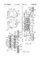
- FIG. 1is a side plan view of a vertebral body T-cage constructed according to the teachings of the present invention for installation intermediate the endplates of vertebrae located immediately above and below a removed vertebra, showing a vertebrae support column having a mounting plate attached to the side thereof, and also showing two blood holes extending through the vertebrae support column;
- FIG. 2is a back plan view of the vertebral body T-cage illustrated in FIG. 1, showing a plurality of apertures through which mounting screws may be inserted to retain the vertebral body T-cage in place;
- FIG. 3is a top plan view of the vertebral body T-cage illustrated in FIGS. 1 and 2, showing that the vertebrae support column has a square configuration and is hollow;
- FIG. 4is a side plan view of an alternate embodiment vertebral body T-cage, showing the vertebrae support column with upper and lower edges which are curved in a convex manner;
- FIG. 5is a back plan view of the vertebral body T-cage illustrated in FIG. 4, showing the mounting plate to consist of two opposed L-shaped segments having a common base leg;
- FIG. 6is a top plan view of the vertebral body T-cage illustrated in FIGS. 4 and 5, showing the square configuration of the hollow vertebrae support column;
- FIG. 7is a cross-sectional view of the vertebral body T-cage illustrated in FIGS. 4 through 6, showing the angle of one of the apertures through which a mounting screw may be inserted to retain the vertebral body T-cage in place;
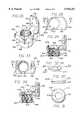
- FIG. 8is a side plan view of an alternate embodiment vertebral body T-cage having a curved mounting plate
- FIG. 9is a back plan view of the vertebral body T-cage illustrated in FIG. 8;
- FIG. 10is a top plan view of the vertebral body T-cage illustrated in FIGS. 8 and 9, showing the square configuration of the hollow vertebrae support column;
- FIG. 11is a cross-sectional view of the vertebral body T-cage illustrated in FIGS. 8 through 10;
- FIG. 12is a top side (superior) plan view of the vertebral body T-cage illustrated in FIGS. 8 through 10 located on the superior endplate of a lower vertebra which is located immediately below a removed vertebra;
- FIG. 13is an anterior side view of the vertebral body T-cage illustrated in FIG. 12 installed between upper and lower vertebra respectively located immediately above and below a removed vertebra;
- FIG. 14is a side plan view of a fixed height vertebral body prosthesis constructed according to the teachings of the present invention for right side installation intermediate the endplates of vertebrae located immediately above and below a removed vertebra, showing a vertebrae support column having mounting brackets attached to the top and bottom thereof, and also showing a plurality of blood holes extending therethrough;
- FIG. 15is a top plan view of the mounting bracket mounted on the top of the vertebrae support column of the vertebral body prosthesis illustrated in FIG. 14, showing the configuration of a curved side mounting plate located thereon;
- FIG. 16is a bottom plan view of the mounting bracket mounted on the bottom of the vertebrae support column of the vertebral body prosthesis illustrated in FIG. 14, showing the configuration of a curved side mounting plate located thereon;
- FIG. 17is a back plan view of the vertebral body prosthesis illustrated in FIGS. 14 through 16, showing a plurality of apertures through which mounting screws may be inserted to retain the vertebral body prosthesis in place;
- FIG. 18is a cross-sectional view of the vertebral body prosthesis illustrated in FIGS. 14 through 17, showing the hollow interior of the vertebrae support column;
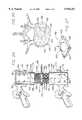
- FIG. 19is an exploded side view of a variable height vertebral body prosthesis constructed according to the teachings of the present invention for right side installation intermediate the endplates of vertebrae located immediately above and below a removed vertebra, showing top and bottom mounting brackets for respective installation onto threaded top and bottom ends of a vertebrae support column;
- FIG. 20is a top plan view of the top mounting bracket for installation on the threaded top end of the vertebrae support column of the vertebral body prosthesis illustrated in FIG. 19, showing the hollow threaded interior thereof and the configuration of a curved side mounting plate located thereon;
- FIG. 21is a bottom plan view of the bottom mounting bracket for installation on the threaded bottom end of the vertebrae support column of the vertebral body prosthesis illustrated in FIG. 19, showing the hollow threaded interior thereof and the configuration of a curved side mounting plate located thereon;
- FIG. 22is a top end view of the vertebrae support column of the vertebral body prosthesis illustrated in FIG. 19, showing the hollow interior thereof;
- FIG. 23is a cross-sectional view of the vertebral body prosthesis illustrated in FIGS. 19 through 22, showing the installation of the top and bottom mounting brackets respectively onto the threaded top and bottom ends of the vertebrae support column;
- FIG. 24is a right side view of the vertebral body prosthesis illustrated in FIGS. 19 through 23 installed between upper and lower vertebra respectively located immediately above and below a removed vertebra, showing a handle inserted into apertures located at the midpoint of the vertebrae support column and used to adjust the height of the vertebral body prosthesis;
- FIG. 25is a top side (superior) plan view of the upper vertebra showing the vertebral body prosthesis illustrated in FIG. 24 located under the inferior endplate of the upper vertebra;
- FIG. 26is a perspective view of an alternate embodiment top mounting bracket having a plurality of small spikes located thereon to secure the top mounting bracket in place under the inferior endplate of an upper vertebra;
- FIG. 27is a perspective view of a wedge-shaped spacer for use intermediate a mounting bracket and the endplate of a vertebrae to better fit the mounting bracket to the surface of the endplate of the vertebra;
- FIG. 28is a top plan view of an alternate embodiment top mounting bracket having an annular recess located in the top surface thereof around the hollow threaded interior thereof;
- FIG. 29is a cross-sectional view of the top mounting bracket illustrated in FIG. 28, showing the depth of the annular recess located in the top surface thereof;
- FIG. 30is a side view of a rotatable wedge spacer for installation in the annular recess located in the top surface of the top mounting bracket illustrated in FIGS. 28 and 29;
- FIG. 31is a bottom plan view of the rotatable wedge spacer illustrated in FIG. 30, showing a centrally-located aperture extending therethrough;
- FIG. 32is a perspective view of a convex segment of a sphere having a centrally-located aperture extending therethrough;
- FIG. 33is a top plan view of another alternate embodiment top mounting bracket having a concave recess located in the top surface thereof around the hollow threaded interior thereof;
- FIG. 34is a cross-sectional view of the top mounting bracket illustrated in FIG. 33, showing the convex segment illustrated in FIG. 32 located in and extending above the concave recess located in the top surface of the top mounting bracket to form a wedge on the top surface of the top mounting bracket.
- the preferred embodiment of the vertebral body prosthesis of the present inventionincludes three basic embodiments, each of which will be described in this detailed description.
- the first of these embodimentsis a vertebral body T-cage, which is fixed in height, and is for installation intermediate the endplates of two vertebrae located immediately above and below a removed vertebra.
- the T-cagewhich may be used in the cervical spine (located in the neck) and which may be installed from an anterior surgical approach, is illustrated in and described in conjunction with FIGS. 1 through 13.
- the second embodimentis a fixed height vertebral body prosthesis for installation intermediate the endplates of vertebrae located immediately above and below a removed vertebra.
- the fixed height vertebral body prosthesismay be installed using a posterior surgical approach, and has curved mounting plates located on the left or right side of the vertebrae. It is illustrated in and described in conjunction with FIGS. 14 through 18.
- the third embodimentis a variable height vertebral body prosthesis, also for installation intermediate the endplates of vertebrae located immediately above and below a removed vertebra.
- the variable height vertebral body prosthesisis similar to the fixed height vertebral body prosthesis in design and in its installation, differing only in that its height may be adjusted once it is installed in place. It is illustrated in and described in conjunction with FIGS. 19 through 25.
- a vertebral body T-cage 40which essentially consists of a vertebrae support column 42 having a flat rectangular mounting plate 44 attached to the side thereof.
- the side of the vertebrae support column 42is attached to the mounting plate 44 at the midpoint of the mounting plate 44, thereby forming a T in which the vertebrae support column 42 is the base of the T and the mounting plate 44 is the top-mounted cross member of the T.
- the vertebrae support column 42is square in cross-section, as illustrated in FIG. 3, and is hollow, having a square aperture 46 extending vertically therethrough.
- the vertebrae support column 42is flat on both its top and its bottom, as best illustrated in FIGS. 1 and 2.
- the vertebrae support column 42has a plurality of blood holes 48 extending through the lateral and anterior sides (and, although not shown in the figures, the posterior side) thereof (and thus through the mounting plate 44 as well).
- the blood holes 48define a plurality of paths of fluid communication between the square aperture 46 extending through the vertebrae support column 42 and the exterior of the vertebrae support column 42 on the lateral, anterior, and posterior sides thereof.
- a plurality of apertures 50extend through the mounting plate 44 both above and below its point of connection to the vertebrae support column 42.
- the apertures 50are arranged and configured to have mounting screws (not illustrated in FIG. 2) inserted therethrough to retain the vertebral body T-cage 40 in place intermediate two vertebrae (also not illustrated in FIG. 2).
- the screws extending through the apertures 50 located above the point of connection of the mounting plate 44 to the vertebrae support column 42will be screwed into the upper vertebra, while the screws extending through the apertures 50 located below the point of connection of the mounting plate 44 to the vertebrae support column 42 will be screwed into the lower vertebra.
- FIGS. 4 through 7an alternate embodiment vertebral body T-cage 52 is illustrated which essentially consists of a vertebrae support column 54 having a flat mounting plate 56 attached to the side thereof.
- the side of the vertebrae support column 54is attached to the mounting plate 56 at the midpoint of the mounting plate 56.
- the vertebrae support column 54is square in cross-section, as illustrated in FIG. 6, and is hollow, having a square aperture 58 extending vertically therethrough.
- the lateral sides of the vertebrae support column 54are convex curves on both the top and bottom of the vertebrae support column 54, as best illustrated in FIGS. 4 and 7. Note also that the height of the vertebrae support column 54 is greater at the anterior side thereof than it is at the posterior side thereof.
- the vertebrae support column 54has a plurality of blood holes 60 extending through the lateral and anterior sides (and, although not shown in the figures, the posterior side) thereof (and thus through the mounting plate 56 as well).
- the blood holes 60define a plurality of paths of fluid communication between the square aperture 58 extending through the vertebrae support column 54 and the exterior of the vertebrae support column 54 on the lateral, anterior, and posterior sides thereof.
- the mounting plate 56consists of two 180 degree opposed L's having their respective bases mounted together, with their respective vertical legs extending in opposing directions from different ends of the common bases.
- the legs of the L's of the mounting plate 56each have a pair of countersunk apertures 62 extending therethrough.
- the screws extending through the countersunk apertures 62 located in the leg of the L above the point of connection of the mounting plate 56 to the vertebrae support column 54will be screwed into the upper vertebra, while the screws extending through the countersunk apertures 62 located in the leg of the L below the point of connection of the mounting plate 56 to the vertebrae support column 54 will be screwed into the lower vertebra.
- two countersunk angled apertures 64are also located in the mounting plate 56 at its point of connection to the vertebrae support column 54 (the bases of the L's).
- One of the countersunk angled apertures 64is oriented such that a screw (not illustrated in FIG. 5) inserted therethrough will engage an upper vertebra (not illustrated in FIG. 5), and the other of the countersunk angled apertures 64 is oriented such that another screw inserted therethrough will engage a lower vertebra (also not illustrated in FIG. 5).
- FIGS. 8 through 11another alternate embodiment vertebral body T-cage 66 is illustrated which essentially consists of a vertebrae support column 68 having a curved mounting plate 70 attached to the side thereof.
- the side of the vertebrae support column 68is attached to the curved mounting plate 70 at the midpoint of the curved mounting plate 70.
- the vertebrae support column 68is square in cross-section, as illustrated in FIG. 10, and is hollow, having a square aperture 72 extending vertically therethrough.
- the lateral sides of the vertebrae support column 68are convex curves on both the top and bottom of the vertebrae support column 68, as best illustrated in FIGS. 8 and 11.
- the vertebrae support column 68has a plurality of blood holes 74 extending through the lateral and anterior sides (and, although not shown in the figures, the posterior side) thereof (and thus through the mounting plate 70 as well).
- the blood holes 74define a plurality of paths of fluid communication between the square aperture 72 extending through the vertebrae support column 68 and the exterior of the vertebrae support column 68 on the lateral, anterior, and posterior sides thereof.
- a plurality of countersunk apertures 76extend through the curved mounting plate 70 both above and below its point of connection to the vertebrae support column 68.
- the countersunk apertures 76are arranged and configured to have mounting screws (not illustrated in FIG. 9) inserted therethrough to retain the vertebral body T-cage 66 in place intermediate two vertebrae (also not illustrated in FIG. 9).
- One of the countersunk angled apertures 78is oriented such that a screw (not illustrated in FIG. 9) inserted therethrough will engage an upper vertebra (not illustrated in FIG. 9), and the other of the countersunk angled apertures 78 is oriented such that another screw inserted therethrough will engage a lower vertebra (also not illustrated in FIG. 9).
- the vertebral body T-cage 66is illustrated as being installed intermediate a superior endplate 80 of a lower vertebra 82 and an inferior endplate 84 of an upper vertebra 86.
- the vertebral body T-cage 66is installed following the removal of a vertebra (not illustrated) which was located intermediate the lower vertebra 82 and the upper vertebra 86.
- the vertebrae support column 68 of the vertebral body T-cage 66is first packed with bone chips or marrow (not illustrated) and then is placed intermediate the superior endplate 80 of the lower vertebra 82 and the inferior endplate 84 of the upper vertebra 86.
- a pair of screws 88are inserted through the countersunk apertures 76 in the portion of the curved mounting plate 70 extending above the vertebrae support column 68 (illustrated in FIG. 9), and are screwed into the upper vertebra 86.
- Another pair of screws 90are then inserted through the countersunk apertures 76 in the portion of the curved mounting plate 70 extending below the vertebrae support column 68 (also illustrated in FIG. 9), and are screwed into the lower vertebra 82.
- a screw 92is inserted through the countersunk angled aperture 78 which is angled downwardly in the vertebral body T-cage 66, and is screwed into the lower vertebra 82.
- a screw 94is inserted through the countersunk angled aperture 78 which is angled upwardly in the vertebral body T-cage 66, and is screwed into the upper vertebra 86.
- FIGS. 14 through 18a fixed height vertebral body prosthesis 100 for installation intermediate the endplates of vertebrae (not illustrated in FIGS. 14 through 18) located immediately above and below a removed vertebra is illustrated.
- the fixed height vertebral body prosthesis 100is for installation from the right side of the vertebrae, although it will at once be understood by those skilled in the art that the mirror image of the fixed height vertebral body prosthesis 100 could be used for installation from the left side of the vertebrae.
- the fixed height vertebral body prosthesis 100consists of a vertebrae support column 102 having an upper mounting bracket 104 mounted at the top thereof, and a lower mounting bracket 106 mounted at the bottom thereof.
- the vertebrae support column 102is of cylindrical configuration, and is hollow.
- a plurality of blood holes 108extend through the sides of the vertebrae support column 102, and define a plurality of paths of fluid communication between the interior and the exterior of the vertebrae support column 102.
- the upper mounting bracket 104is illustrated to include a flat base member 110 having a curved mounting plate 112 mounted at one side thereof and extending upwardly therefrom.
- the base member 110 of the upper mounting bracket 104has a circular aperture 114 extending vertically therethrough, which circular aperture 114 is in communication with the hollow interior of the vertebrae support column 102, as illustrated in FIG. 18.
- a plurality of blood holes 116extend through the sides of the base member 110, and define a plurality of paths of fluid communication between the interior and the exterior of the base member 110.
- a plurality of apertures 118extend through the curved mounting plate 112 above its point of connection to the base member 110.
- the apertures 118are arranged and configured to have mounting screws (not illustrated in FIGS. 17 and 18) inserted therethrough to retain the upper mounting bracket 104 in place adjacent an upper vertebra (not illustrated in FIGS. 17 and 18) with the base member 110 under the endplate of the upper vertebra.
- the screws extending through the apertures 118will be screwed into the upper vertebra to retain the upper mounting bracket 104 in place.
- the lower mounting bracket 106is illustrated to include a flat base member 120 having a curved mounting plate 122 mounted at one side thereof and extending downwardly therefrom.
- the base member 120 of the lower mounting bracket 106has a circular aperture 124 extending vertically therethrough, which circular aperture 124 is in communication with the hollow interior of the vertebrae support column 102, as illustrated in FIG. 18.
- a plurality of blood holes 126extend through the sides of the base member 120, and define a plurality of paths of fluid communication between the interior and the exterior of the base member 120.
- a plurality of apertures 128extend through the curved mounting plate 122 below its point of connection to the base member 120.
- the apertures 128are arranged and configured to have mounting screws (not illustrated in FIGS. 17 and 18) inserted therethrough to retain the lower mounting bracket 106 in place adjacent a lower vertebra (not illustrated in FIGS. 17 and 18) with the base member 120 on top of the endplate of the lower vertebra.
- the screws extending through the apertures 128will be screwed into the lower vertebra to retain the lower mounting bracket 106 in place.
- variable height vertebral body prosthesis 130for installation intermediate the endplates of vertebrae (not illustrated in FIGS. 19 through 23) located immediately above and below a removed vertebra is illustrated.
- the variable height vertebral body prosthesis 130is for installation from the right side of the vertebrae, although it will at once be understood by those skilled in the art that the mirror image of the variable height vertebral body prosthesis 130 could be used for installation from the left side of the vertebra.
- the variable height vertebral body prosthesis 130consists of three components which are assembled together. These three components are a vertebrae support column 132, an upper mounting bracket 134 for installation at the top of the vertebrae support column 132, and a lower mounting bracket 136 for installation at the bottom of the vertebrae support column 132.
- the vertebrae support column 132is of essentially cylindrical configuration, and is hollow, having a circular aperture 133 extending therethrough.
- the top end of the vertebrae support column 132has standard threads 138 located on the outside thereof.
- the bottom end of the vertebrae support column 132has reverse threads 140 located on the outside thereof.
- a central portionwhich has a series of angularly spaced apertures 142 extending radially therethrough.
- the angularly spaced apertures 142will be used to adjust the height of the variable height vertebral body prosthesis 130, as will become apparent below in conjunction with the discussion of FIGS. 24 and 25.
- a plurality of blood holes 144extend through the sides of the vertebrae support column 132, and define a plurality of paths of fluid communication between the interior and the exterior of the vertebrae support column 132.
- the upper mounting bracket 134is illustrated to include a flat base member 146 mounted atop a cylindrical support 148.
- the base member 146has a curved mounting plate 150 mounted at one side thereof and extending upwardly therefrom.
- the base member 146 and the cylindrical support 148 of the upper mounting bracket 134have a standard threaded circular aperture 152 extending vertically therethrough, which standard threaded circular aperture 152 will receive the standard threaded end 138 of the vertebrae support column 132.
- the standard threaded circular aperture 152 in the upper mounting bracket 134is in communication with the circular aperture 133 extending through the vertebrae support column 132, as illustrated in FIG. 23.
- a plurality of blood holes 154extend through the sides of the base member 146 and the cylindrical support 148, and define a plurality of paths of fluid communication relatively between the interiors and the exteriors thereof. Also located in the side of the cylindrical support 148 in a location which will be accessible during the installation of the variable height vertebral body prosthesis 130 is a threaded aperture 156.
- a plurality of apertures 158extend through the curved mounting plate 150 above its point of connection to the base member 146.
- the apertures 158are arranged and configured to have mounting screws (not illustrated in FIGS. 19 and 23) inserted therethrough to retain the upper mounting bracket 134 in place adjacent an upper vertebra (not illustrated in FIGS. 19 and 23) with the base member 146 under the endplate of the upper vertebra.
- the screws extending through the apertures 158will be screwed into the upper vertebra to retain the upper mounting bracket 134 in place.
- the lower mounting bracket 136is illustrated to include a flat base member 160 mounted atop a cylindrical support 162.
- the base member 160has a curved mounting plate 164 mounted at one side thereof and extending upwardly therefrom.
- the base member 160 and the cylindrical support 162 of the lower mounting bracket 136have a reverse threaded circular aperture 166 extending vertically therethrough, which reverse threaded circular aperture 166 will receive the reverse threaded end 140 of the vertebrae support column 132.
- the reverse threaded circular aperture 166 in the lower mounting bracket 136is in communication with the circular aperture 133 extending through the vertebrae support column 132, as illustrated in FIG. 23.
- a plurality of blood holes 168extend through the sides of the base member 160 and the cylindrical support 162, and define a plurality of paths of fluid communication relatively between the interiors and the exteriors thereof. Also located in the side of the cylindrical support 162 in a location which will be accessible during the installation of the variable height vertebral body prosthesis 130 is a threaded aperture 170.
- a plurality of apertures 172extend through the curved mounting plate 164 above its point of connection to the base member 160.
- the apertures 172are arranged and configured to have mounting screws (not illustrated in FIGS. 19 and 23) inserted therethrough to retain the lower mounting bracket 136 in place adjacent a lower vertebra (not illustrated in FIGS. 19 and 23) with the base member 160 under the endplate of the lower vertebra.
- the screws extending through the apertures 172will be screwed into the lower vertebra to retain the lower mounting bracket 136 in place.
- variable height vertebral body prosthesis 130is illustrated as being installed intermediate a superior endplate 174 of a lower vertebra 176 and an inferior endplate 178 of an upper vertebra 180.
- the variable height vertebral body prosthesis 130is installed following the removal of a vertebra (not illustrated) which was located intermediate the lower vertebra 176 and the upper vertebra 180.
- the circular aperture 133 in the vertebrae support column 132, the standard threaded circular aperture 152 in the upper mounting bracket 134, and the reverse threaded circular aperture 166 in the lower mounting bracket 136are first packed with bone chips or marrow (not illustrated).
- the variable height vertebral body prosthesis 130is then placed intermediate the superior endplate 174 of the lower vertebra 176 and the inferior endplate 178 of the upper vertebra 180.
- a handle 186is inserted into an opposed pair of the angularly spaced apertures 142 located at the midpoint of the vertebrae support column 132.
- the handle 186is used to rotate the vertebrae support column 132 to adjust the height of the variable height vertebral body prosthesis 130.
- the upper mounting bracket 134 and the lower mounting bracket 136will move further apart, thereby increasing the height of the variable height vertebral body prosthesis 130.
- the upper mounting bracket 134 and the lower mounting bracket 136will move closer together, thereby decreasing the height of the variable height vertebral body prosthesis 130.
- a setscrew 188is screwed into the threaded aperture 156 in the cylindrical support 148 of the upper mounting bracket 134 (illustrated in FIG. 19) and into engagement with the standard threaded end 138 of the vertebrae support column 132.
- a setscrew 190is screwed into the threaded aperture 170 in the cylindrical support 162 of the lower mounting bracket 136 (illustrated in FIG. 19) and into engagement with the reverse threaded end 140 of the vertebrae support column 132.
- an alternate embodiment upper mounting bracket 192is illustrated which uses the same reference numerals as the upper mounting bracket 134 (illustrated in FIGS. 19, 20, and 23) for identical parts thereof.
- the upper mounting bracket 192differs from the upper mounting bracket 134 only in that the upper mounting bracket 192 has a plurality of small spikes 194 extending from the superior side of the base member 146.
- the spikes 194are for use to better retain the upper mounting bracket 192 in position against the inferior endplate 178 of the upper vertebra 180 (illustrated in FIG. 24).
- FIG. 27another alternate embodiment component is illustrated, which is for use with either the upper mounting bracket 134 or the lower mounting bracket 136 (illustrated in FIGS. 19 through 23).
- a wedge-shaped spacer 196is illustrated which is for use intermediate a mounting bracket (the upper mounting bracket 134 or the lower mounting bracket 136) and a vertebra endplate (the inferior endplate 178 of the upper vertebra 180 or the superior endplate 174 of the lower vertebra 176) to better fit the mounting bracket to the surface of the endplate of the vertebra.
- the wedge-shaped spacer 196consists of a rectangular, wedge-shaped member 198 having a circular aperture 200 extending vertically therethrough.
- the circular aperture 200has a plurality of small spikes 202 extending from the superior side of the wedge-shaped member 198.
- the spikes 202are optional, and act to better retain the wedge-shaped spacer 196 in position against a vertebra endplate (the inferior endplate 178 of the upper vertebra 180 or the superior endplate 174 of the lower vertebra 176).
- FIGS. 28 and 29another alternate embodiment upper mounting bracket 204 is illustrated which uses the same reference numerals as the upper mounting bracket 134 (illustrated in FIGS. 19, 20, and 23) for identical parts thereof.
- the upper mounting bracket 204differs from the upper mounting bracket 134 only in that the upper mounting bracket 204 has an annular recess 206 located in the top surface of the base member 146 around the standard threaded circular aperture 152. The depth of the annular recess 206 is illustrated in FIG. 29.
- a rotatable wedge spacer 208is illustrated which consists of a short cylindrical base 210 having a cylindrical segment of a wedge 212 mounted thereupon.
- a centrally-located circular aperture 214extends vertically through both the cylindrical wedge 212 and the cylindrical base 210, as illustrated in FIG. 31.
- the rotatable wedge spacer 208is for installation on the upper mounting bracket 204 illustrated in FIGS. 28 and 29.
- the height of the cylindrical base 210 of the rotatable wedge spacer 208is of a size to fit within the annular recess 206 located in the top surface of the base member 146 of the upper mounting bracket 204.
- a convex member 216which consists of a spherical segment 218 having a flat top surface (e.g., a minority portion of a sphere which has been cut off by a plane).
- the spherical segment 218 of the convex member 216has a centrally-located circular aperture 220 extending therethrough.
- FIGS. 33 and 34yet another alternate embodiment upper mounting bracket 222 is illustrated which uses the same reference numerals as the upper mounting bracket 134 (illustrated in FIGS. 19, 20, and 23) for identical parts thereof.
- the upper mounting bracket 222differs from the upper mounting bracket 134 only in that the upper mounting bracket 222 has a concave recess 224 located in the top surface of the base member 146 around the standard threaded circular aperture 152.
- the depth of the concave recess 224is illustrated in FIG. 34.
- the spherical segment 218 of the convex member 216is arranged and configured to fit partially within the concave recess 224 in the base member 146 of the upper mounting bracket 222. Since the spherical segment 218 of the convex member 216 is free to move within the concave recess 224 in the base member 146 of the upper mounting bracket 222, it will be appreciated by those skilled in the art that the portion of the spherical segment 218 of the convex member 216 which is located above the surface of the base member 146 of the upper mounting bracket 222 will act as a wedge, moving to accommodate different uneven surface configurations on the endplate of a vertebra (not illustrated in FIGS. 32 through 34) on which the upper mounting bracket 22 is to be mounted.
- the vertebral body prosthesis of the present inventionis of a design and physical configuration which may be easily installed in place intermediate the endplates of the two adjacent vertebrae via a posterior surgical approach.
- the implant procedure for the vertebral body prosthesis of the present inventionalso does not require the use of complex tools to install and position the vertebral body prosthesis intermediate the two vertebrae.
- the vertebral body prosthesis of the present inventionis implantable in a surgical procedure featuring both reduced implant trauma to the patient and reduced time required for the surgeon to implant the device.
- the vertebral body prosthesis of the present inventionWhen the vertebral body prosthesis of the present invention is installed in place intermediate the vertebrae located immediately above and below the removed vertebra, it will securely and permanently maintain the integrity and security of the spinal column.
- the vertebral body prosthesis of the present inventionpromotes prompt and permanent ingrowth of bone material intermediate the vertebrae located immediately above and below the removed vertebra to facilitate permanent fusion of the spinal segment.
- the vertebral body prosthesis of the present inventionis made of biocompatible material compatible with long term implant in the human body, and it may be either adjustable in length or made in different sizes and configurations to fit a wide variety of patients and different locations in the spine.
- the vertebral body prosthesis of the present inventionis of a construction which is both durable and long lasting, and it requires no maintenance once it is implanted.
- the vertebral body prosthesis of the present inventionis also of a simple mechanical design and relatively inexpensive construction to enhance its market appeal and thereby afford it the broadest possible market. Finally, all of the aforesaid advantages and objectives of the vertebral body prosthesis of the present invention are achieved without incurring any substantial relative disadvantage.
Landscapes
- Health & Medical Sciences (AREA)
- Orthopedic Medicine & Surgery (AREA)
- Engineering & Computer Science (AREA)
- Biomedical Technology (AREA)
- Heart & Thoracic Surgery (AREA)
- Cardiology (AREA)
- Oral & Maxillofacial Surgery (AREA)
- Transplantation (AREA)
- Neurology (AREA)
- Vascular Medicine (AREA)
- Life Sciences & Earth Sciences (AREA)
- Animal Behavior & Ethology (AREA)
- General Health & Medical Sciences (AREA)
- Public Health (AREA)
- Veterinary Medicine (AREA)
- Prostheses (AREA)
Abstract
Description
Claims (23)
Priority Applications (3)
| Application Number | Priority Date | Filing Date | Title |
|---|---|---|---|
| US08/826,000US5916267A (en) | 1997-04-07 | 1997-04-07 | Anterior spinal implant system for vertebral body prosthesis |
| PCT/US1998/006670WO1998044878A1 (en) | 1997-04-07 | 1998-04-03 | Anterior spinal implant system for vertebrae replacement |
| AU71015/98AAU7101598A (en) | 1997-04-07 | 1998-04-03 | Anterior spinal implant system for vertebrae replacement |
Applications Claiming Priority (1)
| Application Number | Priority Date | Filing Date | Title |
|---|---|---|---|
| US08/826,000US5916267A (en) | 1997-04-07 | 1997-04-07 | Anterior spinal implant system for vertebral body prosthesis |
Publications (1)
| Publication Number | Publication Date |
|---|---|
| US5916267Atrue US5916267A (en) | 1999-06-29 |
Family
ID=25245434
Family Applications (1)
| Application Number | Title | Priority Date | Filing Date |
|---|---|---|---|
| US08/826,000Expired - Fee RelatedUS5916267A (en) | 1997-04-07 | 1997-04-07 | Anterior spinal implant system for vertebral body prosthesis |
Country Status (3)
| Country | Link |
|---|---|
| US (1) | US5916267A (en) |
| AU (1) | AU7101598A (en) |
| WO (1) | WO1998044878A1 (en) |
Cited By (154)
| Publication number | Priority date | Publication date | Assignee | Title |
|---|---|---|---|---|
| US6190413B1 (en)* | 1998-04-16 | 2001-02-20 | Ulrich Gmbh & Co. Kg | Vertebral implant |
| US6200348B1 (en)* | 1998-02-06 | 2001-03-13 | Biedermann, Motech Gmbh | Spacer with adjustable axial length |
| US6210442B1 (en)* | 1996-07-15 | 2001-04-03 | Aesculap Ag & Co. Kg | Implant for vertebral body fusion |
| US20020016583A1 (en)* | 2000-02-16 | 2002-02-07 | Cragg Andrew H. | Methods of performing procedures in the spine |
| US6375681B1 (en)* | 1998-06-23 | 2002-04-23 | Ebi, L.P. | Vertebral body replacement |
| US6395030B1 (en) | 1998-06-18 | 2002-05-28 | Michigan Technological University | Spinal fixation system |
| US6395034B1 (en)* | 1999-11-24 | 2002-05-28 | Loubert Suddaby | Intervertebral disc prosthesis |
| FR2817462A1 (en)* | 2000-12-05 | 2002-06-07 | Stryker Spine Sa | IN SITU INTERSOMATIC SPINAL IMPLANT WITH HARD PASSAGE POINTS |
| US6447413B1 (en)* | 1999-02-01 | 2002-09-10 | Eric S. Turer | Field serviceable derailleur device |
| US20020169508A1 (en)* | 1998-06-18 | 2002-11-14 | Pioneer Laboratories, Inc. | Spinal fixation system |
| US20030004572A1 (en)* | 2001-03-02 | 2003-01-02 | Goble E. Marlowe | Method and apparatus for spine joint replacement |
| US6562073B2 (en) | 2001-02-06 | 2003-05-13 | Sdgi Holding, Inc. | Spinal bone implant |
| US6576017B2 (en) | 2001-02-06 | 2003-06-10 | Sdgi Holdings, Inc. | Spinal implant with attached ligament and methods |
| US20030158557A1 (en)* | 2000-02-16 | 2003-08-21 | Cragg Andrew H. | Method and apparatus for spinal distraction and fusion |
| US20030191532A1 (en)* | 2000-11-29 | 2003-10-09 | Goble E. Marlowe | Facet joint replacement |
| US20030195518A1 (en)* | 2000-02-16 | 2003-10-16 | Cragg Andrew H. | Methods and apparatus for performing therapeutic procedures in the spine |
| US6635086B2 (en) | 2000-05-30 | 2003-10-21 | Blacksheep Technologies Incorporated | Implant for placement between cervical vertebrae |
| US20030212399A1 (en)* | 2002-02-25 | 2003-11-13 | Dinh Dzung H. | Methods and apparatuses for promoting fusion of vertebrae |
| EP1247503A3 (en)* | 2001-04-02 | 2003-12-17 | Ulrich GmbH & Co. KG | Implant for insertion between two vertebral bodies of the spine |
| US20040010316A1 (en)* | 2002-03-30 | 2004-01-15 | Lytton William | Intervertebral device and method of use |
| US20040024462A1 (en)* | 2002-04-12 | 2004-02-05 | Ferree Bret A. | Spacerless artificial disc replacements |
| US20040073311A1 (en)* | 2002-04-23 | 2004-04-15 | Ferree Bret A. | Two-component artificial disc replacements |
| US20040092929A1 (en)* | 2002-09-27 | 2004-05-13 | Zindrick Michael R. | Spinal plate with means to secure a graft |
| US20040127993A1 (en)* | 2002-10-16 | 2004-07-01 | Erich Kast | Spreader implant for placement between vertebrae |
| WO2004049915A3 (en)* | 2000-02-16 | 2004-08-19 | Trans1 Inc | Method and apparatus for spinal distraction and fusion |
| US20040167626A1 (en)* | 2003-01-23 | 2004-08-26 | Geremakis Perry A. | Expandable artificial disc prosthesis |
| US6783547B2 (en) | 2002-04-05 | 2004-08-31 | Howmedica Corp. | Apparatus for fusing adjacent bone structures |
| US20040176773A1 (en)* | 2003-03-06 | 2004-09-09 | Rafail Zubok | Instrumentation and methods for use in implanting a cervical disc replacement device |
| US20040186570A1 (en)* | 2001-04-04 | 2004-09-23 | Rapp Lawrence G | Interbody spinal fusion device |
| US20040210312A1 (en)* | 2003-03-15 | 2004-10-21 | Carsten Neumann | Implant for insertion between vertebrae of the spinal column |
| US20040210310A1 (en)* | 2002-12-10 | 2004-10-21 | Trieu Hai H. | Implant system and method for intervertebral disc augmentation |
| US6824565B2 (en) | 2000-09-08 | 2004-11-30 | Nabil L. Muhanna | System and methods for inserting a vertebral spacer |
| US20040254582A1 (en)* | 1998-08-20 | 2004-12-16 | Bonutti Peter M. | Joint spacer |
| US6837905B1 (en)* | 2002-09-26 | 2005-01-04 | Daniel M. Lieberman | Spinal vertebral fusion implant and method |
| US20050027362A1 (en)* | 1999-02-26 | 2005-02-03 | Williams Lytton A. | Method and apparatus for intervertebral implant anchorage |
| US20050055095A1 (en)* | 2001-07-16 | 2005-03-10 | Errico Joseph P. | Artificial intervertebral disc trials having a cylindrical engagement surface |
| US20050080486A1 (en)* | 2000-11-29 | 2005-04-14 | Fallin T. Wade | Facet joint replacement |
| US6902579B2 (en)* | 2000-12-27 | 2005-06-07 | Biedermann Motech Gmbh | Lengthwise adjustable space-maintainer for inserting between two vertebral bodies |
| US20050137602A1 (en)* | 2003-10-23 | 2005-06-23 | Assell Robert L. | Method and apparatus for spinal distraction |
| US20050154459A1 (en)* | 2003-10-20 | 2005-07-14 | Howard Wolek | Vertebral body replacement apparatus and method |
| US20050228501A1 (en)* | 2003-09-15 | 2005-10-13 | Sdgi Holdings, Inc. | Spinal implant system |
| US20050228497A1 (en)* | 2002-04-23 | 2005-10-13 | Ferree Bret A | Artificial disc replacements with natural kinematics |
| US20050283155A1 (en)* | 2004-06-21 | 2005-12-22 | Michael Jacene | Instruments and methods for holding a bone plate |
| US20060058800A1 (en)* | 2002-12-03 | 2006-03-16 | Trans1 Inc. | Methods and apparatus for provision of therapy to adjacent motion segments |
| US20060074490A1 (en)* | 2004-10-01 | 2006-04-06 | Sweeney Patrick J | Vertebral prosthesis and spinal fixation system |
| US20060136062A1 (en)* | 2004-12-17 | 2006-06-22 | Dinello Alexandre | Height-and angle-adjustable motion disc implant |
| US20060241762A1 (en)* | 2003-12-11 | 2006-10-26 | Deltacor Gmbh | Height-adjustable spinal implant and operating instrument for the implant |
| US20070073311A1 (en)* | 2005-09-26 | 2007-03-29 | Williams Lytton A | System and method for intervertebral implant delivery and removal |
| US20070123985A1 (en)* | 2005-05-27 | 2007-05-31 | Spinecore, Inc. | Intervertebral disc and insertion methods therefor |
| US20070255421A1 (en)* | 2006-04-27 | 2007-11-01 | Sdgi Holdings, Inc. | Locking expandable implant and method |
| US20070255408A1 (en)* | 2006-04-27 | 2007-11-01 | Sdgi Holdings, Inc. | Stabilized, adjustable expandable implant and method |
| US20080015704A1 (en)* | 2006-06-28 | 2008-01-17 | Ulrich Gmbh & Co.Kg | Vertebral implant |
| US20080051890A1 (en)* | 2006-08-11 | 2008-02-28 | Warsaw Orthopedic, Inc. | Intervertebral Implants with Attachable Flanges and Methods of Use |
| US20080065076A1 (en)* | 2000-02-16 | 2008-03-13 | Cragg Andrew H | Spinal mobility preservation apparatus |
| US20090062917A1 (en)* | 2007-08-27 | 2009-03-05 | Foley Kevin T | Spinal interbody replacement devices |
| US7507242B2 (en) | 2004-06-02 | 2009-03-24 | Facet Solutions | Surgical measurement and resection framework |
| US20090088849A1 (en)* | 2007-09-27 | 2009-04-02 | Warsaw Orthopedic, Inc. | Intervertebral Implant |
| US20090112325A1 (en)* | 2007-10-30 | 2009-04-30 | Biospine, Llc | Footplate member and a method for use in a vertebral body replacement device |
| US20090112324A1 (en)* | 2007-10-30 | 2009-04-30 | Biospine, Llc | Vertebral body replacement device and method for use to maintain a space between two vertebral bodies within a spine |
| US20090118834A1 (en)* | 2007-04-01 | 2009-05-07 | Spinal Kinetics, Inc. | Expandable Prosthetic Intervertebral Discs That Are Implantable By Minimally Invasive Surgical Techniques |
| US20090164017A1 (en)* | 2007-12-19 | 2009-06-25 | Robert Sommerich | Expandable Corpectomy Spinal Fusion Cage |
| US20090164018A1 (en)* | 2007-12-19 | 2009-06-25 | Robert Sommerich | Instruments For Expandable Corpectomy Spinal Fusion Cage |
| US7566345B1 (en) | 2001-03-01 | 2009-07-28 | Facet Solutions, Inc | Prosthesis for the replacement of a posterior element of a vertebra |
| US20090216331A1 (en)* | 2008-02-22 | 2009-08-27 | Innvotec Surgicals, Inc. | Spinal Implant with expandable fixation |
| US7588590B2 (en) | 2003-12-10 | 2009-09-15 | Facet Solutions, Inc | Spinal facet implant with spherical implant apposition surface and bone bed and methods of use |
| US20090270929A1 (en)* | 2008-04-24 | 2009-10-29 | Loubert Suddaby | Facet joint fixation device |
| US7637952B2 (en) | 2002-03-11 | 2009-12-29 | Zimmer Spine, Inc. | Instrumentation and procedure for implanting spinal implant devices |
| US20100004657A1 (en)* | 2008-01-18 | 2010-01-07 | Spinecore, Inc. | Instruments and methods for inserting artificial intervertebral implants |
| US20100100186A1 (en)* | 2003-03-06 | 2010-04-22 | Spinecore, Inc. | Instrumentation and methods for use in implanting a cervical disc replacement device |
| US7713302B2 (en) | 2001-10-01 | 2010-05-11 | Spinecore, Inc. | Intervertebral spacer device utilizing a spirally slotted belleville washer having radially spaced concentric grooves |
| US7722647B1 (en) | 2005-03-14 | 2010-05-25 | Facet Solutions, Inc. | Apparatus and method for posterior vertebral stabilization |
| US7727263B2 (en) | 2000-02-16 | 2010-06-01 | Trans1, Inc. | Articulating spinal implant |
| US7771477B2 (en) | 2001-10-01 | 2010-08-10 | Spinecore, Inc. | Intervertebral spacer device utilizing a belleville washer having radially spaced concentric grooves |
| US7799081B2 (en) | 2004-09-14 | 2010-09-21 | Aeolin, Llc | System and method for spinal fusion |
| US20100241231A1 (en)* | 2009-02-20 | 2010-09-23 | Marino James F | Intervertebral fixation device |
| US20100280616A1 (en)* | 2009-04-29 | 2010-11-04 | William Frasier | Minimally invasive corpectomy cage and instrument |
| US20100324687A1 (en)* | 2009-06-18 | 2010-12-23 | Warsaw Orthopedic, Inc. | Intervertebral implant with a pivoting end cap |
| US7879096B2 (en) | 2006-04-27 | 2011-02-01 | Warsaw Orthopedic, Inc. | Centrally driven expandable implant |
| US7887595B1 (en) | 2005-12-05 | 2011-02-15 | Nuvasive, Inc. | Methods and apparatus for spinal fusion |
| US20110040329A1 (en)* | 2009-08-14 | 2011-02-17 | Ainsworth Stephen D | Spinal therapy device with fixated distraction distance |
| US7914581B2 (en) | 2006-04-27 | 2011-03-29 | Warsaw Orthopedic, Inc. | Expandable implant, instrument, and method |
| US7981157B2 (en) | 2006-04-27 | 2011-07-19 | Warsaw Orthopedic, Inc. | Self-contained expandable implant and method |
| US7993373B2 (en) | 2005-02-22 | 2011-08-09 | Hoy Robert W | Polyaxial orthopedic fastening apparatus |
| US8029568B2 (en) | 2001-10-18 | 2011-10-04 | Spinecore, Inc. | Intervertebral spacer device having a slotted partial circular domed arch strip spring |
| US20110270395A1 (en)* | 2010-04-28 | 2011-11-03 | Warsaw Orthopedic, Inc. | Device and method for delivering radiation in selected directions |
| US20120022654A1 (en)* | 2009-04-13 | 2012-01-26 | Biospine, Llc | Variable height intervertebral devices and methods for use |
| US8114162B1 (en) | 2006-08-09 | 2012-02-14 | Nuvasive, Inc. | Spinal fusion implant and related methods |
| US20120059471A1 (en)* | 2004-09-23 | 2012-03-08 | Cervitech, Inc. | Prosthesis for partial replacement of a vertebral body |
| US8142441B2 (en) | 2008-10-16 | 2012-03-27 | Aesculap Implant Systems, Llc | Surgical instrument and method of use for inserting an implant between two bones |
| US8142435B2 (en) | 2009-02-19 | 2012-03-27 | Aesculap Implant Systems, Llc | Multi-functional surgical instrument and method of use for inserting an implant between two bones |
| US8206418B2 (en) | 2007-01-10 | 2012-06-26 | Gmedelaware 2 Llc | System and method for facet joint replacement with detachable coupler |
| US20120283781A1 (en)* | 2009-11-25 | 2012-11-08 | Uri Arnin | Spinal rod having a post-operative adjustable dimension |
| US8377140B2 (en) | 2011-01-12 | 2013-02-19 | Ebi, Llc | Expandable spinal implant device |
| US20130053894A1 (en)* | 2011-08-31 | 2013-02-28 | Depuy Spine, Inc. | Devices and methods for cervical lateral fixation |
| US8454694B2 (en) | 2011-03-03 | 2013-06-04 | Warsaw Orthopedic, Inc. | Interbody device and plate for spinal stabilization and instruments for positioning same |
| US8480747B2 (en) | 2010-08-11 | 2013-07-09 | Warsaw Orthopedic, Inc. | Interbody spinal implants with extravertebral support plates |
| US8480715B2 (en)* | 2007-05-22 | 2013-07-09 | Zimmer Spine, Inc. | Spinal implant system and method |
| US20130190875A1 (en)* | 2005-09-26 | 2013-07-25 | Coalign Innovations, Inc. | Selectively Expanding Spine Cage With Enhanced Bone Graft Infusion |
| US8562649B2 (en) | 2004-02-17 | 2013-10-22 | Gmedelaware 2 Llc | System and method for multiple level facet joint arthroplasty and fusion |
| US8568482B2 (en) | 2003-05-14 | 2013-10-29 | Kilian Kraus | Height-adjustable implant to be inserted between vertebral bodies and corresponding handling tool |
| US8628575B2 (en) | 2000-08-29 | 2014-01-14 | Nabil L. Muhanna | Vertebral body replacement and method of use |
| US8740980B2 (en) | 2011-01-27 | 2014-06-03 | Warsaw Orthopedic, Inc. | Expandable medical implant |
| US8764801B2 (en) | 2005-03-28 | 2014-07-01 | Gmedelaware 2 Llc | Facet joint implant crosslinking apparatus and method |
| USD708747S1 (en) | 2006-09-25 | 2014-07-08 | Nuvasive, Inc. | Spinal fusion implant |
| US8795363B2 (en) | 1998-06-30 | 2014-08-05 | Bonutti Skeletal Innovations Llc | Wedge apparatus for use in operating on a bone |
| US8894710B2 (en) | 2008-12-10 | 2014-11-25 | Coalign Innovations, Inc. | Lockable spinal implant |
| US8900273B2 (en) | 2005-02-22 | 2014-12-02 | Gmedelaware 2 Llc | Taper-locking fixation system |
| US8992620B2 (en) | 2008-12-10 | 2015-03-31 | Coalign Innovations, Inc. | Adjustable distraction cage with linked locking mechanisms |
| US8992617B2 (en) | 2007-03-13 | 2015-03-31 | DePuy Synthes Products, LLC | Adjustable intervertebral implant |
| US9034046B2 (en) | 2007-10-30 | 2015-05-19 | Aesculap Implant Systems, Llc | Vertebral body replacement device and method for use to maintain a space between two vertebral bodies within a spine |
| US9095444B2 (en) | 2009-07-24 | 2015-08-04 | Warsaw Orthopedic, Inc. | Implant with an interference fit fastener |
| US9566167B2 (en) | 2013-08-22 | 2017-02-14 | K2M, Inc. | Expandable spinal implant |
| US20170128231A1 (en)* | 2010-06-24 | 2017-05-11 | DePuy Synthes Products, Inc. | Lateral Spondylolisthesis Reduction Cage |
| US9700425B1 (en) | 2011-03-20 | 2017-07-11 | Nuvasive, Inc. | Vertebral body replacement and insertion methods |
| US9730804B2 (en) | 2009-09-06 | 2017-08-15 | Warsaw Orthopedic, Inc. | Locking spinal fusion device |
| US20170246010A1 (en)* | 2016-02-28 | 2017-08-31 | Life Spine, Inc. | Expandable Corpectomy Spine Implant |
| US9814598B2 (en) | 2013-03-14 | 2017-11-14 | Quandary Medical, Llc | Spinal implants and implantation system |
| US20170354511A1 (en)* | 2016-06-10 | 2017-12-14 | Globus Medical, Inc. | Vertebral implants and attachment assemblies |
| US9877840B2 (en) | 2008-09-04 | 2018-01-30 | DePuy Synthes Products, Inc. | Adjustable intervertebral implant |
| US9968460B2 (en) | 2013-03-15 | 2018-05-15 | Medsmart Innovation Inc. | Dynamic spinal segment replacement |
| CN109077835A (en)* | 2018-10-26 | 2018-12-25 | 北京爱康宜诚医疗器材有限公司 | Centrum prosthese |
| US10363142B2 (en) | 2014-12-11 | 2019-07-30 | K2M, Inc. | Expandable spinal implants |
| US10441430B2 (en) | 2017-07-24 | 2019-10-15 | K2M, Inc. | Expandable spinal implants |
| US10470891B2 (en) | 2016-09-12 | 2019-11-12 | Howmedica Osteonics Corp. | Interbody implant with independent control of expansion at multiple locations |
| US10485675B2 (en) | 2016-10-26 | 2019-11-26 | Howmedica Osteonics Corp. | Expandable interbody implant with lateral articulation |
| US10548738B2 (en) | 2016-04-07 | 2020-02-04 | Howmedica Osteonics Corp. | Expandable interbody implant |
| CN110840636A (en)* | 2019-11-20 | 2020-02-28 | 北京爱康宜诚医疗器材有限公司 | Vertebral prosthesis |
| US10729553B2 (en) | 2017-09-15 | 2020-08-04 | Stryker European Operations Holdings Llc | Intervertebral body fusion device expanded with hardening material |
| US10940018B2 (en) | 2016-05-20 | 2021-03-09 | Howmedica Osteonics Corp. | Expandable interbody implant with lordosis correction |
| US20210205094A1 (en)* | 2010-09-03 | 2021-07-08 | Globus Medical, Inc. | Expandable fusion device and method of installation thereof |
| US11344424B2 (en) | 2017-06-14 | 2022-05-31 | Medos International Sarl | Expandable intervertebral implant and related methods |
| US11369490B2 (en) | 2011-03-22 | 2022-06-28 | DePuy Synthes Products, Inc. | Universal trial for lateral cages |
| US11426290B2 (en) | 2015-03-06 | 2022-08-30 | DePuy Synthes Products, Inc. | Expandable intervertebral implant, system, kit and method |
| US11432942B2 (en) | 2006-12-07 | 2022-09-06 | DePuy Synthes Products, Inc. | Intervertebral implant |
| US11446155B2 (en) | 2017-05-08 | 2022-09-20 | Medos International Sarl | Expandable cage |
| US11446156B2 (en) | 2018-10-25 | 2022-09-20 | Medos International Sarl | Expandable intervertebral implant, inserter instrument, and related methods |
| US11452607B2 (en) | 2010-10-11 | 2022-09-27 | DePuy Synthes Products, Inc. | Expandable interspinous process spacer implant |
| US11497619B2 (en) | 2013-03-07 | 2022-11-15 | DePuy Synthes Products, Inc. | Intervertebral implant |
| US11510788B2 (en) | 2016-06-28 | 2022-11-29 | Eit Emerging Implant Technologies Gmbh | Expandable, angularly adjustable intervertebral cages |
| US11596522B2 (en) | 2016-06-28 | 2023-03-07 | Eit Emerging Implant Technologies Gmbh | Expandable and angularly adjustable intervertebral cages with articulating joint |
| US11602438B2 (en) | 2008-04-05 | 2023-03-14 | DePuy Synthes Products, Inc. | Expandable intervertebral implant |
| US11607321B2 (en) | 2009-12-10 | 2023-03-21 | DePuy Synthes Products, Inc. | Bellows-like expandable interbody fusion cage |
| US11612491B2 (en) | 2009-03-30 | 2023-03-28 | DePuy Synthes Products, Inc. | Zero profile spinal fusion cage |
| US11622868B2 (en) | 2007-06-26 | 2023-04-11 | DePuy Synthes Products, Inc. | Highly lordosed fusion cage |
| US11654033B2 (en) | 2010-06-29 | 2023-05-23 | DePuy Synthes Products, Inc. | Distractible intervertebral implant |
| US11737881B2 (en) | 2008-01-17 | 2023-08-29 | DePuy Synthes Products, Inc. | Expandable intervertebral implant and associated method of manufacturing the same |
| US11752009B2 (en) | 2021-04-06 | 2023-09-12 | Medos International Sarl | Expandable intervertebral fusion cage |
| US11806245B2 (en) | 2020-03-06 | 2023-11-07 | Eit Emerging Implant Technologies Gmbh | Expandable intervertebral implant |
| US11850160B2 (en) | 2021-03-26 | 2023-12-26 | Medos International Sarl | Expandable lordotic intervertebral fusion cage |
| US11872139B2 (en) | 2010-06-24 | 2024-01-16 | DePuy Synthes Products, Inc. | Enhanced cage insertion assembly |
| USRE49973E1 (en) | 2013-02-28 | 2024-05-21 | DePuy Synthes Products, Inc. | Expandable intervertebral implant, system, kit and method |
| US12090064B2 (en) | 2022-03-01 | 2024-09-17 | Medos International Sarl | Stabilization members for expandable intervertebral implants, and related systems and methods |
| US12232975B2 (en) | 2008-02-22 | 2025-02-25 | Howmedica Osteonics Corp. | Lockable spinal implant |
| US12440346B2 (en) | 2023-03-31 | 2025-10-14 | DePuy Synthes Products, Inc. | Expandable intervertebral implant |
Families Citing this family (3)
| Publication number | Priority date | Publication date | Assignee | Title |
|---|---|---|---|---|
| ES2156805B1 (en) | 1999-02-11 | 2002-02-01 | Darder Jose Manuel Gonzalez | BOX-PLATE FOR STABILIZATION OF THE CERVICAL COLUMN. |
| DE10210214B4 (en)* | 2002-03-02 | 2005-01-05 | Bernd Schäfer | Distractable spinal implant and tool for distraction |
| DE102010004275A1 (en)* | 2010-01-11 | 2011-07-21 | Metz-Stavenhagen, Peter, Dr. med., 34537 | Vertebral body spacer |
Citations (4)
| Publication number | Priority date | Publication date | Assignee | Title |
|---|---|---|---|---|
| DE3729600A1 (en)* | 1987-09-04 | 1989-03-16 | Aesculap Werke Ag | Implant for insertion between the vertebral bodies of the spine |
| US5236460A (en)* | 1990-02-12 | 1993-08-17 | Midas Rex Pneumatic Tools, Inc. | Vertebral body prosthesis |
| US5458641A (en)* | 1993-09-08 | 1995-10-17 | Ramirez Jimenez; Juan J. | Vertebral body prosthesis |
| US5571192A (en)* | 1994-07-02 | 1996-11-05 | Heinrich Ulrich | Prosthetic vertebral implant |
- 1997
- 1997-04-07USUS08/826,000patent/US5916267A/ennot_activeExpired - Fee Related
- 1998
- 1998-04-03AUAU71015/98Apatent/AU7101598A/ennot_activeAbandoned
- 1998-04-03WOPCT/US1998/006670patent/WO1998044878A1/enactiveApplication Filing
Patent Citations (4)
| Publication number | Priority date | Publication date | Assignee | Title |
|---|---|---|---|---|
| DE3729600A1 (en)* | 1987-09-04 | 1989-03-16 | Aesculap Werke Ag | Implant for insertion between the vertebral bodies of the spine |
| US5236460A (en)* | 1990-02-12 | 1993-08-17 | Midas Rex Pneumatic Tools, Inc. | Vertebral body prosthesis |
| US5458641A (en)* | 1993-09-08 | 1995-10-17 | Ramirez Jimenez; Juan J. | Vertebral body prosthesis |
| US5571192A (en)* | 1994-07-02 | 1996-11-05 | Heinrich Ulrich | Prosthetic vertebral implant |
Cited By (388)
| Publication number | Priority date | Publication date | Assignee | Title |
|---|---|---|---|---|
| US6210442B1 (en)* | 1996-07-15 | 2001-04-03 | Aesculap Ag & Co. Kg | Implant for vertebral body fusion |
| US6200348B1 (en)* | 1998-02-06 | 2001-03-13 | Biedermann, Motech Gmbh | Spacer with adjustable axial length |
| US6190413B1 (en)* | 1998-04-16 | 2001-02-20 | Ulrich Gmbh & Co. Kg | Vertebral implant |
| US20020169508A1 (en)* | 1998-06-18 | 2002-11-14 | Pioneer Laboratories, Inc. | Spinal fixation system |
| US6395030B1 (en) | 1998-06-18 | 2002-05-28 | Michigan Technological University | Spinal fixation system |
| US6682561B2 (en)* | 1998-06-18 | 2004-01-27 | Pioneer Laboratories, Inc. | Spinal fixation system |
| US6375681B1 (en)* | 1998-06-23 | 2002-04-23 | Ebi, L.P. | Vertebral body replacement |
| US9050152B2 (en) | 1998-06-30 | 2015-06-09 | Bonutti Skeletal Innovations Llc | Method and apparatus for use in operating on a bone |
| US9044322B2 (en) | 1998-06-30 | 2015-06-02 | Bonutti Skeletal Innovations Llc | Method and apparatus for use in operating on a bone |
| US8795363B2 (en) | 1998-06-30 | 2014-08-05 | Bonutti Skeletal Innovations Llc | Wedge apparatus for use in operating on a bone |
| US9044341B2 (en)* | 1998-08-20 | 2015-06-02 | Bonutti Skeletal Innovations Llc | Joint spacer |
| US20040254582A1 (en)* | 1998-08-20 | 2004-12-16 | Bonutti Peter M. | Joint spacer |
| US8956417B2 (en) | 1998-08-20 | 2015-02-17 | Bonutti Skeletal Innovations Llc | Joint spacer |
| US6447413B1 (en)* | 1999-02-01 | 2002-09-10 | Eric S. Turer | Field serviceable derailleur device |
| US20050027362A1 (en)* | 1999-02-26 | 2005-02-03 | Williams Lytton A. | Method and apparatus for intervertebral implant anchorage |
| US6395034B1 (en)* | 1999-11-24 | 2002-05-28 | Loubert Suddaby | Intervertebral disc prosthesis |
| US20080065076A1 (en)* | 2000-02-16 | 2008-03-13 | Cragg Andrew H | Spinal mobility preservation apparatus |
| US8709087B2 (en) | 2000-02-16 | 2014-04-29 | Baxano Surgical, Inc. | Methods and apparatus for performing therapeutic procedures in the spine |
| US7014633B2 (en) | 2000-02-16 | 2006-03-21 | Trans1, Inc. | Methods of performing procedures in the spine |
| US8317867B2 (en) | 2000-02-16 | 2012-11-27 | Trans1 Inc. | Methods and apparatus for performing therapeutic procedures in the spine |
| US7905908B2 (en) | 2000-02-16 | 2011-03-15 | Trans1, Inc. | Spinal mobility preservation method |
| US7905905B2 (en) | 2000-02-16 | 2011-03-15 | Trans1, Inc. | Spinal mobility preservation apparatus |
| US7727263B2 (en) | 2000-02-16 | 2010-06-01 | Trans1, Inc. | Articulating spinal implant |
| US7309338B2 (en) | 2000-02-16 | 2007-12-18 | Trans1 Inc. | Methods and apparatus for performing therapeutic procedures in the spine |
| US7608077B2 (en) | 2000-02-16 | 2009-10-27 | Trans1 Inc. | Method and apparatus for spinal distraction and fusion |
| US20030195518A1 (en)* | 2000-02-16 | 2003-10-16 | Cragg Andrew H. | Methods and apparatus for performing therapeutic procedures in the spine |
| US6921403B2 (en)* | 2000-02-16 | 2005-07-26 | Trans1 Inc. | Method and apparatus for spinal distraction and fusion |
| US7547317B2 (en) | 2000-02-16 | 2009-06-16 | Trans1 Inc. | Methods of performing procedures in the spine |
| WO2004049915A3 (en)* | 2000-02-16 | 2004-08-19 | Trans1 Inc | Method and apparatus for spinal distraction and fusion |
| US20030158557A1 (en)* | 2000-02-16 | 2003-08-21 | Cragg Andrew H. | Method and apparatus for spinal distraction and fusion |
| US7794463B2 (en) | 2000-02-16 | 2010-09-14 | Trans1 Inc. | Methods and apparatus for performing therapeutic procedures in the spine |
| US8105365B2 (en) | 2000-02-16 | 2012-01-31 | Trans1 Inc. | Methods and apparatus for performing therapeutic procedures in the spine |
| US20020016583A1 (en)* | 2000-02-16 | 2002-02-07 | Cragg Andrew H. | Methods of performing procedures in the spine |
| US8292928B2 (en) | 2000-02-16 | 2012-10-23 | Trans1 Inc. | Method and apparatus for spinal distraction and fusion |
| US7744599B2 (en) | 2000-02-16 | 2010-06-29 | Trans1 Inc. | Articulating spinal implant |
| US6635086B2 (en) | 2000-05-30 | 2003-10-21 | Blacksheep Technologies Incorporated | Implant for placement between cervical vertebrae |
| US9468539B2 (en) | 2000-08-29 | 2016-10-18 | Nabil L. Muhanna, M.D. | Vertebral body replacement and method of use |
| US8628575B2 (en) | 2000-08-29 | 2014-01-14 | Nabil L. Muhanna | Vertebral body replacement and method of use |
| US20110071637A1 (en)* | 2000-09-08 | 2011-03-24 | Muhanna Nabil L | System and methods for inserting a vertebral spacer |
| US20050071009A1 (en)* | 2000-09-08 | 2005-03-31 | Nabil L. Muhanna, M.D. | System and methods for inserting a vertebral spacer |
| US6824565B2 (en) | 2000-09-08 | 2004-11-30 | Nabil L. Muhanna | System and methods for inserting a vertebral spacer |
| US7618453B2 (en) | 2000-11-29 | 2009-11-17 | Facet Solutions, Inc | Facet joint replacement |
| US8313511B2 (en) | 2000-11-29 | 2012-11-20 | Gmedelaware 2 Llc | Facet joint replacement |
| US7041136B2 (en) | 2000-11-29 | 2006-05-09 | Facet Solutions, Inc. | Facet joint replacement |
| US20050080486A1 (en)* | 2000-11-29 | 2005-04-14 | Fallin T. Wade | Facet joint replacement |
| US20030191532A1 (en)* | 2000-11-29 | 2003-10-09 | Goble E. Marlowe | Facet joint replacement |
| US7621955B2 (en) | 2000-11-29 | 2009-11-24 | Facet Solutions, Inc. | Facet joint replacement |
| US20050209697A1 (en)* | 2000-12-05 | 2005-09-22 | Stryker Spine | Spinal intervertebral implant adjustable in situ comprising hard pass point |
| US7156874B2 (en) | 2000-12-05 | 2007-01-02 | Stryker Spine | Spinal intervertebral implant adjustable in situ comprising hard pass point |
| WO2002045625A1 (en)* | 2000-12-05 | 2002-06-13 | Stryker Spine | Spinal intervertebral implant adjustable in situ comprising hard pass points |
| FR2817462A1 (en)* | 2000-12-05 | 2002-06-07 | Stryker Spine Sa | IN SITU INTERSOMATIC SPINAL IMPLANT WITH HARD PASSAGE POINTS |
| US6902579B2 (en)* | 2000-12-27 | 2005-06-07 | Biedermann Motech Gmbh | Lengthwise adjustable space-maintainer for inserting between two vertebral bodies |
| US20030167092A1 (en)* | 2001-02-06 | 2003-09-04 | Foley Kevin T. | Spinal bone implant |
| US7354452B2 (en)* | 2001-02-06 | 2008-04-08 | Warsaw Orthopedic, Inc. | Spinal bone implant |
| US6576017B2 (en) | 2001-02-06 | 2003-06-10 | Sdgi Holdings, Inc. | Spinal implant with attached ligament and methods |
| US6562073B2 (en) | 2001-02-06 | 2003-05-13 | Sdgi Holding, Inc. | Spinal bone implant |
| US20030195632A1 (en)* | 2001-02-06 | 2003-10-16 | Foley Kevin T. | Spinal implant with attached ligament |
| US7566345B1 (en) | 2001-03-01 | 2009-07-28 | Facet Solutions, Inc | Prosthesis for the replacement of a posterior element of a vertebra |
| US7090698B2 (en) | 2001-03-02 | 2006-08-15 | Facet Solutions | Method and apparatus for spine joint replacement |
| US20050234551A1 (en)* | 2001-03-02 | 2005-10-20 | Facet Solutions, Inc. | Method and apparatus for spine joint replacement |
| US7955390B2 (en) | 2001-03-02 | 2011-06-07 | GME Delaware 2 LLC | Method and apparatus for spine joint replacement |
| US20030004572A1 (en)* | 2001-03-02 | 2003-01-02 | Goble E. Marlowe | Method and apparatus for spine joint replacement |
| US7445635B2 (en) | 2001-03-02 | 2008-11-04 | Facet Solutions | Method and apparatus for spine joint replacement |
| EP1247503A3 (en)* | 2001-04-02 | 2003-12-17 | Ulrich GmbH & Co. KG | Implant for insertion between two vertebral bodies of the spine |
| US6805714B2 (en)* | 2001-04-02 | 2004-10-19 | Ulrich Gmbh & Co. Kg | Anchorable vertebral implant |
| US7887588B2 (en)* | 2001-04-04 | 2011-02-15 | Rapp Lawrence G | Interbody spinal fusion device |
| US20070276375A1 (en)* | 2001-04-04 | 2007-11-29 | Rapp Lawrence G | Interbody spinal fusion device |
| US20040186570A1 (en)* | 2001-04-04 | 2004-09-23 | Rapp Lawrence G | Interbody spinal fusion device |
| US20100174371A9 (en)* | 2001-07-16 | 2010-07-08 | Errico Joseph P | Artificial intervertebral disc trials having a cylindrical engagement surface |
| US8357167B2 (en) | 2001-07-16 | 2013-01-22 | Spinecore, Inc. | Artificial intervertebral disc trials with baseplates having inward tool engagement holes |
| US20050055095A1 (en)* | 2001-07-16 | 2005-03-10 | Errico Joseph P. | Artificial intervertebral disc trials having a cylindrical engagement surface |
| US8092539B2 (en) | 2001-10-01 | 2012-01-10 | Spinecore, Inc. | Intervertebral spacer device having a belleville washer with concentric grooves |
| US7713302B2 (en) | 2001-10-01 | 2010-05-11 | Spinecore, Inc. | Intervertebral spacer device utilizing a spirally slotted belleville washer having radially spaced concentric grooves |
| US7771477B2 (en) | 2001-10-01 | 2010-08-10 | Spinecore, Inc. | Intervertebral spacer device utilizing a belleville washer having radially spaced concentric grooves |
| US8029568B2 (en) | 2001-10-18 | 2011-10-04 | Spinecore, Inc. | Intervertebral spacer device having a slotted partial circular domed arch strip spring |
| US7186254B2 (en) | 2002-02-25 | 2007-03-06 | Dinh Dzung H | Methods and apparatus for promoting fusion of vertebrae |
| US20030212399A1 (en)* | 2002-02-25 | 2003-11-13 | Dinh Dzung H. | Methods and apparatuses for promoting fusion of vertebrae |
| US7637952B2 (en) | 2002-03-11 | 2009-12-29 | Zimmer Spine, Inc. | Instrumentation and procedure for implanting spinal implant devices |
| US7717959B2 (en) | 2002-03-30 | 2010-05-18 | Lytton William | Intervertebral device and method of use |
| US8632594B2 (en) | 2002-03-30 | 2014-01-21 | Infinity Orthopaedics Company, Ltd | Intervertebral device and method of use |
| US20070010887A1 (en)* | 2002-03-30 | 2007-01-11 | Williams Lytton A | Intervertebral Device and Method of Use |
| US20040010316A1 (en)* | 2002-03-30 | 2004-01-15 | Lytton William | Intervertebral device and method of use |
| US6783547B2 (en) | 2002-04-05 | 2004-08-31 | Howmedica Corp. | Apparatus for fusing adjacent bone structures |
| US8679182B2 (en) | 2002-04-12 | 2014-03-25 | Spinecore, Inc. | Spacerless artificial disc replacements |
| US10786363B2 (en) | 2002-04-12 | 2020-09-29 | Spinecore, Inc. | Spacerless artificial disc replacements |
| US20040024462A1 (en)* | 2002-04-12 | 2004-02-05 | Ferree Bret A. | Spacerless artificial disc replacements |
| US8470041B2 (en) | 2002-04-12 | 2013-06-25 | Spinecore, Inc. | Two-component artificial disc replacements |
| US9198773B2 (en) | 2002-04-12 | 2015-12-01 | Spinecore, Inc. | Spacerless artificial disc replacements |
| US10271956B2 (en) | 2002-04-12 | 2019-04-30 | Spinecore, Inc. | Spacerless artificial disc replacements |
| US8801789B2 (en) | 2002-04-12 | 2014-08-12 | Spinecore, Inc. | Two-component artificial disc replacements |
| US20080027548A9 (en)* | 2002-04-12 | 2008-01-31 | Ferree Bret A | Spacerless artificial disc replacements |
| US20100241233A1 (en)* | 2002-04-12 | 2010-09-23 | Spinecore, Inc. | Spacerless artificial disc replacements |
| US8277507B2 (en) | 2002-04-12 | 2012-10-02 | Spinecore, Inc. | Spacerless artificial disc replacements |
| US8038713B2 (en) | 2002-04-23 | 2011-10-18 | Spinecore, Inc. | Two-component artificial disc replacements |
| US8784492B2 (en) | 2002-04-23 | 2014-07-22 | Spinecore, Inc. | Artificial disc replacements with natural kinematics |
| US9168146B2 (en) | 2002-04-23 | 2015-10-27 | Spinecore, Inc. | Artificial disc replacements with natural kinematics |
| US20050228497A1 (en)* | 2002-04-23 | 2005-10-13 | Ferree Bret A | Artificial disc replacements with natural kinematics |
| US9572679B2 (en) | 2002-04-23 | 2017-02-21 | Spinecore, Inc. | Artificial disc replacements with natural kinematics |
| US10299933B2 (en) | 2002-04-23 | 2019-05-28 | Spinecore, Inc. | Artificial disc replacements with natural kinematics |
| US20040073311A1 (en)* | 2002-04-23 | 2004-04-15 | Ferree Bret A. | Two-component artificial disc replacements |
| US9877841B2 (en) | 2002-04-23 | 2018-01-30 | Spinecore, Inc. | Artificial disc replacements with natural kinematics |
| US8366772B2 (en) | 2002-04-23 | 2013-02-05 | Spinecore, Inc. | Artificial disc replacements with natural kinematics |
| US6837905B1 (en)* | 2002-09-26 | 2005-01-04 | Daniel M. Lieberman | Spinal vertebral fusion implant and method |
| US20040092929A1 (en)* | 2002-09-27 | 2004-05-13 | Zindrick Michael R. | Spinal plate with means to secure a graft |
| US20040127993A1 (en)* | 2002-10-16 | 2004-07-01 | Erich Kast | Spreader implant for placement between vertebrae |
| US8523918B2 (en) | 2002-12-03 | 2013-09-03 | Baxano Surgical, Inc. | Therapy to adjacent motion segments |
| US20060058800A1 (en)* | 2002-12-03 | 2006-03-16 | Trans1 Inc. | Methods and apparatus for provision of therapy to adjacent motion segments |
| US7776042B2 (en) | 2002-12-03 | 2010-08-17 | Trans1 Inc. | Methods and apparatus for provision of therapy to adjacent motion segments |
| US8328847B2 (en) | 2002-12-03 | 2012-12-11 | Trans1 Inc. | Assemblies for provision of therapy to motion segments |
| US8167947B2 (en) | 2002-12-03 | 2012-05-01 | Trans1 Inc. | Methods for push distraction and for provision of therapy to adjacent motion segments |
| US20040210310A1 (en)* | 2002-12-10 | 2004-10-21 | Trieu Hai H. | Implant system and method for intervertebral disc augmentation |
| US20040167626A1 (en)* | 2003-01-23 | 2004-08-26 | Geremakis Perry A. | Expandable artificial disc prosthesis |
| US20100100186A1 (en)* | 2003-03-06 | 2010-04-22 | Spinecore, Inc. | Instrumentation and methods for use in implanting a cervical disc replacement device |
| US20040176777A1 (en)* | 2003-03-06 | 2004-09-09 | Rafail Zubok | Instrumentation and methods for use in implanting a cervical disc replacement device |
| US7708780B2 (en) | 2003-03-06 | 2010-05-04 | Spinecore, Inc. | Instrumentation and methods for use in implanting a cervical disc replacement device |
| US10835385B2 (en) | 2003-03-06 | 2020-11-17 | Howmedica Osteonics Corp. | Instrumentation and methods for use in implanting a cervical disc replacement device |
| US7641665B2 (en) | 2003-03-06 | 2010-01-05 | Spinecore, Inc. | Instrumentation and methods for use in implementing a cervical disc replacement device |
| US20040176773A1 (en)* | 2003-03-06 | 2004-09-09 | Rafail Zubok | Instrumentation and methods for use in implanting a cervical disc replacement device |
| US7637911B2 (en) | 2003-03-06 | 2009-12-29 | Spinecore, Inc. | Instrumentation and methods for use in implanting a cervical disc replacement device |
| US10159578B2 (en) | 2003-03-06 | 2018-12-25 | Spinecore, Inc. | Instrumentation and methods for use in implanting a cervical disc replacement device |
| US20100087870A1 (en)* | 2003-03-06 | 2010-04-08 | Spinecore, Inc. | Instrumentation and methods for use in implanting a cervical disc replacement device |
| US20100076506A1 (en)* | 2003-03-06 | 2010-03-25 | Spinecore, Inc. | Instrumentation and methods for use in implanting a cervical disc replacement device |
| US8936640B2 (en) | 2003-03-06 | 2015-01-20 | Spinecore, Inc. | Cervical disc replacement |
| US20050071013A1 (en)* | 2003-03-06 | 2005-03-31 | Spinecore, Inc. | Instrumentation and methods for use in implanting a cervical disc replacement device |
| US8961608B2 (en) | 2003-03-06 | 2015-02-24 | Spinecore, Inc. | Intervertebral disc replacement |
| US8109979B2 (en) | 2003-03-06 | 2012-02-07 | Spinecore, Inc. | Instrumentation and methods for use in implanting a cervical disc replacement device |
| US20100070040A1 (en)* | 2003-03-06 | 2010-03-18 | Spinecore, Inc. | Intervertebral Disc Replacement |
| US8231628B2 (en) | 2003-03-06 | 2012-07-31 | Spinecore, Inc. | Instrumentation and methods for use in implanting a cervical disc replacement device |
| US10369005B2 (en) | 2003-03-06 | 2019-08-06 | Spinecore, Inc. | Cervical disc replacement |
| US7674292B2 (en) | 2003-03-06 | 2010-03-09 | Spinecore, Inc. | Instrumentation and methods for use in implanting a cervical disc replacement device |
| US9603716B2 (en) | 2003-03-06 | 2017-03-28 | Spinecore, Inc. | Intervertebral disc replacement |
| US8435297B2 (en)* | 2003-03-06 | 2013-05-07 | Spinecore, Inc. | Intervertebral disc replacement |
| US7648511B2 (en) | 2003-03-06 | 2010-01-19 | Spinecore, Inc. | Instrumentation and methods for use in implanting a cervical disc replacement device |
| US9028552B2 (en) | 2003-03-06 | 2015-05-12 | Spinecore, Inc. | Cervical disc replacement |
| US11382762B2 (en) | 2003-03-06 | 2022-07-12 | Howmedica Osteonics Corp. | Instrumentation and methods for use in implanting a cervical disc replacement device |
| US20040210312A1 (en)* | 2003-03-15 | 2004-10-21 | Carsten Neumann | Implant for insertion between vertebrae of the spinal column |
| US8568482B2 (en) | 2003-05-14 | 2013-10-29 | Kilian Kraus | Height-adjustable implant to be inserted between vertebral bodies and corresponding handling tool |
| US7938858B2 (en) | 2003-09-15 | 2011-05-10 | Warsaw Orthopedic, Inc. | Spinal implant system |
| US20050228501A1 (en)* | 2003-09-15 | 2005-10-13 | Sdgi Holdings, Inc. | Spinal implant system |
| US7776093B2 (en) | 2003-10-20 | 2010-08-17 | Blackstone Medical, Inc. | Vertebral body replacement apparatus and method |
| US20050154459A1 (en)* | 2003-10-20 | 2005-07-14 | Howard Wolek | Vertebral body replacement apparatus and method |
| US20050187625A1 (en)* | 2003-10-20 | 2005-08-25 | Howard Wolek | Vertebral body replacement apparatus and method |
| US20050137602A1 (en)* | 2003-10-23 | 2005-06-23 | Assell Robert L. | Method and apparatus for spinal distraction |
| US8308777B2 (en) | 2003-10-23 | 2012-11-13 | Trans1 Inc. | Method and apparatus for removable spinal implant extending between at least two adjacent vertebral bodies |
| US7530993B2 (en) | 2003-10-23 | 2009-05-12 | Trans1 Inc. | Method of spinal fixation |
| US20050165406A1 (en)* | 2003-10-23 | 2005-07-28 | Assell Robert L. | Kits for enabling axial access and procedures in the spine |
| US7799032B2 (en) | 2003-10-23 | 2010-09-21 | Trans1 Inc. | Guide pin introducer for guiding instrumentation through soft tissue to a point on the spine |
| US7473256B2 (en) | 2003-10-23 | 2009-01-06 | Trans1 Inc. | Method and apparatus for spinal distraction |
| US7740633B2 (en) | 2003-10-23 | 2010-06-22 | Trans1 Inc. | Guide pin for guiding instrumentation along a soft tissue tract to a point on the spine |
| US8052613B2 (en) | 2003-10-23 | 2011-11-08 | Trans1 Inc. | Spinal nucleus extraction tool |
| US7799033B2 (en) | 2003-10-23 | 2010-09-21 | Trans1 Inc. | Access kits for enabling axial access and procedures in the spine |
| US7588574B2 (en) | 2003-10-23 | 2009-09-15 | Trans1 Inc. | Kits for enabling axial access and procedures in the spine |
| US7763025B2 (en) | 2003-10-23 | 2010-07-27 | Trans1 Inc. | Spinal fusion kit for guiding instrumentation through soft tissue to a point on the spine |
| US7588590B2 (en) | 2003-12-10 | 2009-09-15 | Facet Solutions, Inc | Spinal facet implant with spherical implant apposition surface and bone bed and methods of use |
| US8419770B2 (en) | 2003-12-10 | 2013-04-16 | Gmedelaware 2 Llc | Spinal facet implants with mating articulating bearing surface and methods of use |
| US8926700B2 (en) | 2003-12-10 | 2015-01-06 | Gmedelware 2 LLC | Spinal facet joint implant |
| US7753937B2 (en) | 2003-12-10 | 2010-07-13 | Facet Solutions Inc. | Linked bilateral spinal facet implants and methods of use |
| US20060241762A1 (en)* | 2003-12-11 | 2006-10-26 | Deltacor Gmbh | Height-adjustable spinal implant and operating instrument for the implant |
| US7998178B2 (en) | 2004-02-17 | 2011-08-16 | Gmedelaware 2 Llc | Linked bilateral spinal facet implants and methods of use |
| US7998177B2 (en) | 2004-02-17 | 2011-08-16 | Gmedelaware 2 Llc | Linked bilateral spinal facet implants and methods of use |
| US8562649B2 (en) | 2004-02-17 | 2013-10-22 | Gmedelaware 2 Llc | System and method for multiple level facet joint arthroplasty and fusion |
| US7914560B2 (en) | 2004-02-17 | 2011-03-29 | Gmedelaware 2 Llc | Spinal facet implant with spherical implant apposition surface and bone bed and methods of use |
| US8906063B2 (en) | 2004-02-17 | 2014-12-09 | Gmedelaware 2 Llc | Spinal facet joint implant |
| US8579941B2 (en) | 2004-02-17 | 2013-11-12 | Alan Chervitz | Linked bilateral spinal facet implants and methods of use |
| US7815648B2 (en) | 2004-06-02 | 2010-10-19 | Facet Solutions, Inc | Surgical measurement systems and methods |
| US7588578B2 (en) | 2004-06-02 | 2009-09-15 | Facet Solutions, Inc | Surgical measurement systems and methods |
| US7507242B2 (en) | 2004-06-02 | 2009-03-24 | Facet Solutions | Surgical measurement and resection framework |
| US8777994B2 (en) | 2004-06-02 | 2014-07-15 | Gmedelaware 2 Llc | System and method for multiple level facet joint arthroplasty and fusion |
| US20050283155A1 (en)* | 2004-06-21 | 2005-12-22 | Michael Jacene | Instruments and methods for holding a bone plate |
| US7604638B2 (en) | 2004-06-21 | 2009-10-20 | Depuy Spine, Inc. | Instruments and methods for holding a bone plate |
| US8298271B2 (en) | 2004-06-21 | 2012-10-30 | Depuy Spine, Inc. | Instruments and methods for holding a bone plate |
| US20100069967A1 (en)* | 2004-06-21 | 2010-03-18 | Michael Jacene | Instruments and Methods For Holding A Bone Plate |
| US8562683B2 (en) | 2004-09-14 | 2013-10-22 | Aeolin Llc | System and method for spinal fusion |
| US7799081B2 (en) | 2004-09-14 | 2010-09-21 | Aeolin, Llc | System and method for spinal fusion |
| US8409285B2 (en)* | 2004-09-23 | 2013-04-02 | Cervitech, Inc. | Prosthesis for partial replacement of a vertebral body |
| US20120059471A1 (en)* | 2004-09-23 | 2012-03-08 | Cervitech, Inc. | Prosthesis for partial replacement of a vertebral body |
| US20110035009A1 (en)* | 2004-10-01 | 2011-02-10 | Spinal Generations, Llc | Vertebral prosthesis and spinal fixation system |
| US9980820B2 (en) | 2004-10-01 | 2018-05-29 | Spinal Generations, Llc | Vertebral prosthesis and spinal fixation system |
| US20060074490A1 (en)* | 2004-10-01 | 2006-04-06 | Sweeney Patrick J | Vertebral prosthesis and spinal fixation system |
| US7883543B2 (en)* | 2004-10-01 | 2011-02-08 | Spinal Generations, Llc | Vertebral prosthesis and spinal fixation system |
| US20060136062A1 (en)* | 2004-12-17 | 2006-06-22 | Dinello Alexandre | Height-and angle-adjustable motion disc implant |
| US7993373B2 (en) | 2005-02-22 | 2011-08-09 | Hoy Robert W | Polyaxial orthopedic fastening apparatus |
| US8900273B2 (en) | 2005-02-22 | 2014-12-02 | Gmedelaware 2 Llc | Taper-locking fixation system |
| US8062336B2 (en) | 2005-02-22 | 2011-11-22 | Gmedelaware 2 Llc | Polyaxial orthopedic fastening apparatus with independent locking modes |
| US7722647B1 (en) | 2005-03-14 | 2010-05-25 | Facet Solutions, Inc. | Apparatus and method for posterior vertebral stabilization |
| US8764801B2 (en) | 2005-03-28 | 2014-07-01 | Gmedelaware 2 Llc | Facet joint implant crosslinking apparatus and method |
| US9622882B2 (en) | 2005-05-27 | 2017-04-18 | Spinecore, Inc. | Intervertebral disc and insertion methods therefor |
| US9782272B2 (en) | 2005-05-27 | 2017-10-10 | Spinecore, Inc. | Intervertebral disc and insertion methods therefor |
| US10245154B2 (en) | 2005-05-27 | 2019-04-02 | Spinecore, Inc. | Instruments and methods for inserting artificial intervertebral implants |
| US8777959B2 (en) | 2005-05-27 | 2014-07-15 | Spinecore, Inc. | Intervertebral disc and insertion methods therefor |
| US11642231B2 (en) | 2005-05-27 | 2023-05-09 | Howmedica Osteonics Corp. | Intervertebral disc and insertion methods therefor |
| US9526634B2 (en) | 2005-05-27 | 2016-12-27 | Spinecore, Inc. | Intervertebral disc and insertion methods therefor |
| US9226837B2 (en) | 2005-05-27 | 2016-01-05 | Spinecore, Inc. | Intervertebral disc and insertion methods therefor |
| US9539114B2 (en) | 2005-05-27 | 2017-01-10 | Spinecore, Inc. | Instruments and methods for inserting artificial intervertebral implants |
| US10213322B2 (en) | 2005-05-27 | 2019-02-26 | Spinecore, Inc. | Intervertebral disc and insertion methods therefor |
| US10835389B2 (en) | 2005-05-27 | 2020-11-17 | Howmedica Osteonics Corp. | Intervertebral disc and insertion methods therefor |
| US20070123985A1 (en)* | 2005-05-27 | 2007-05-31 | Spinecore, Inc. | Intervertebral disc and insertion methods therefor |
| US9095451B2 (en) | 2005-05-27 | 2015-08-04 | Spinecore, Inc. | Intervertebral disc and insertion methods therefor |
| US9028550B2 (en)* | 2005-09-26 | 2015-05-12 | Coalign Innovations, Inc. | Selectively expanding spine cage with enhanced bone graft infusion |
| US20070073311A1 (en)* | 2005-09-26 | 2007-03-29 | Williams Lytton A | System and method for intervertebral implant delivery and removal |
| US20150216676A1 (en)* | 2005-09-26 | 2015-08-06 | Coalign Innovations, Inc. | Selectively expanding spine cage with enhanced bone graft infusion |
| US10610374B2 (en) | 2005-09-26 | 2020-04-07 | Howmedica Osteonics Corp. | Selectively expanding spine cage with enhanced bone graft infusion |
| US9814600B2 (en)* | 2005-09-26 | 2017-11-14 | Howmedica Osteonics Corp. | Selectively expanding spine cage with enhanced bone graft infusion |
| US8435295B2 (en) | 2005-09-26 | 2013-05-07 | Infinity Orthopaedics Company | System and method for intervertebral implant delivery and removal |
| US20100057205A1 (en)* | 2005-09-26 | 2010-03-04 | Infinity Orthopaedics | Universal Spinal Disc Implant System |
| US11564806B2 (en) | 2005-09-26 | 2023-01-31 | Howmedica Osteonics Corp. | Selectively expanding spine cage with enhanced bone graft infusion |
| US20070072475A1 (en)* | 2005-09-26 | 2007-03-29 | Justin Daniel F | Universal spinal disc implant system |
| US7618459B2 (en) | 2005-09-26 | 2009-11-17 | Infinity Orthopedics Ltd. | Universal spinal disc implant system |
| US20130190875A1 (en)* | 2005-09-26 | 2013-07-25 | Coalign Innovations, Inc. | Selectively Expanding Spine Cage With Enhanced Bone Graft Infusion |
| US7887595B1 (en) | 2005-12-05 | 2011-02-15 | Nuvasive, Inc. | Methods and apparatus for spinal fusion |
| US20070255421A1 (en)* | 2006-04-27 | 2007-11-01 | Sdgi Holdings, Inc. | Locking expandable implant and method |
| US8231681B2 (en) | 2006-04-27 | 2012-07-31 | Warsaw Orthopedic | Self-contained expandable implant and method |
| US8366779B2 (en) | 2006-04-27 | 2013-02-05 | Warsaw Orthopedic, Inc. | Expandable implant, instrument, and method |
| US20070255408A1 (en)* | 2006-04-27 | 2007-11-01 | Sdgi Holdings, Inc. | Stabilized, adjustable expandable implant and method |
| US20110087328A1 (en)* | 2006-04-27 | 2011-04-14 | Warsaw Orthopedic, Inc. | Centrally driven expandable implant and method |
| US7981157B2 (en) | 2006-04-27 | 2011-07-19 | Warsaw Orthopedic, Inc. | Self-contained expandable implant and method |
| US20110172779A1 (en)* | 2006-04-27 | 2011-07-14 | Warsaw Orthopedic, Inc. | Expandable Implant, Instrument, and Method |
| US7758648B2 (en)* | 2006-04-27 | 2010-07-20 | Warsaw Orthopedic, Inc. | Stabilized, adjustable expandable implant and method |
| US7575601B2 (en) | 2006-04-27 | 2009-08-18 | Warsaw Orthopedic, Inc. | Locking expandable implant and method |
| US7914581B2 (en) | 2006-04-27 | 2011-03-29 | Warsaw Orthopedic, Inc. | Expandable implant, instrument, and method |
| US8268004B2 (en) | 2006-04-27 | 2012-09-18 | Warsaw Orthopedic, Inc. | Stabilized, adjustable expandable implant and method |
| US20100280614A1 (en)* | 2006-04-27 | 2010-11-04 | Warsaw Orthopedic, Inc. | Stabilized, Adjustable Expandable Implant and Method |
| US7879096B2 (en) | 2006-04-27 | 2011-02-01 | Warsaw Orthopedic, Inc. | Centrally driven expandable implant |
| US20080015704A1 (en)* | 2006-06-28 | 2008-01-17 | Ulrich Gmbh & Co.Kg | Vertebral implant |
| US8070817B2 (en)* | 2006-06-28 | 2011-12-06 | M.O.R.E. Medical Solutions Gmbh | Vertebral implant |
| US8114162B1 (en) | 2006-08-09 | 2012-02-14 | Nuvasive, Inc. | Spinal fusion implant and related methods |
| US20080051890A1 (en)* | 2006-08-11 | 2008-02-28 | Warsaw Orthopedic, Inc. | Intervertebral Implants with Attachable Flanges and Methods of Use |
| US8100975B2 (en) | 2006-08-11 | 2012-01-24 | Warsaw Orthopedic, Inc. | Intervertebral implants with attachable flanges and methods of use |
| USD708747S1 (en) | 2006-09-25 | 2014-07-08 | Nuvasive, Inc. | Spinal fusion implant |
| US11642229B2 (en) | 2006-12-07 | 2023-05-09 | DePuy Synthes Products, Inc. | Intervertebral implant |
| US11660206B2 (en) | 2006-12-07 | 2023-05-30 | DePuy Synthes Products, Inc. | Intervertebral implant |
| US11497618B2 (en) | 2006-12-07 | 2022-11-15 | DePuy Synthes Products, Inc. | Intervertebral implant |
| US11712345B2 (en) | 2006-12-07 | 2023-08-01 | DePuy Synthes Products, Inc. | Intervertebral implant |
| US11432942B2 (en) | 2006-12-07 | 2022-09-06 | DePuy Synthes Products, Inc. | Intervertebral implant |
| US8333789B2 (en) | 2007-01-10 | 2012-12-18 | Gmedelaware 2 Llc | Facet joint replacement |
| US8206418B2 (en) | 2007-01-10 | 2012-06-26 | Gmedelaware 2 Llc | System and method for facet joint replacement with detachable coupler |
| US8211147B2 (en) | 2007-01-10 | 2012-07-03 | Gmedelaware 2 Llc | System and method for facet joint replacement |
| US8252027B2 (en) | 2007-01-10 | 2012-08-28 | Gmedelaware 2 Llc | System and method for facet joint replacement |
| US8308768B2 (en) | 2007-01-10 | 2012-11-13 | Gmedelaware 2 Llc | System and method for facet joint replacement |
| US8992617B2 (en) | 2007-03-13 | 2015-03-31 | DePuy Synthes Products, LLC | Adjustable intervertebral implant |
| US20090118834A1 (en)* | 2007-04-01 | 2009-05-07 | Spinal Kinetics, Inc. | Expandable Prosthetic Intervertebral Discs That Are Implantable By Minimally Invasive Surgical Techniques |
| US8353933B2 (en) | 2007-04-17 | 2013-01-15 | Gmedelaware 2 Llc | Facet joint replacement |
| US9050144B2 (en) | 2007-04-17 | 2015-06-09 | Gmedelaware 2 Llc | System and method for implant anchorage with anti-rotation features |
| US8702759B2 (en) | 2007-04-17 | 2014-04-22 | Gmedelaware 2 Llc | System and method for bone anchorage |
| US8480715B2 (en)* | 2007-05-22 | 2013-07-09 | Zimmer Spine, Inc. | Spinal implant system and method |
| US11622868B2 (en) | 2007-06-26 | 2023-04-11 | DePuy Synthes Products, Inc. | Highly lordosed fusion cage |
| US20090062917A1 (en)* | 2007-08-27 | 2009-03-05 | Foley Kevin T | Spinal interbody replacement devices |
| US20090088849A1 (en)* | 2007-09-27 | 2009-04-02 | Warsaw Orthopedic, Inc. | Intervertebral Implant |
| US8852280B2 (en)* | 2007-09-27 | 2014-10-07 | Warsaw Orthopedic, Inc. | Intervertebral implant |
| USRE48058E1 (en)* | 2007-09-27 | 2020-06-23 | Warsaw Orthopedic, Inc. | Intervertebral implant |
| US20090112324A1 (en)* | 2007-10-30 | 2009-04-30 | Biospine, Llc | Vertebral body replacement device and method for use to maintain a space between two vertebral bodies within a spine |
| US10201432B2 (en) | 2007-10-30 | 2019-02-12 | Aesculap Implant Systems, Llc | Vertebral body replacement device and method for use to maintain a space between two vertebral bodies within a spine |
| US9034046B2 (en) | 2007-10-30 | 2015-05-19 | Aesculap Implant Systems, Llc | Vertebral body replacement device and method for use to maintain a space between two vertebral bodies within a spine |
| US20090112325A1 (en)* | 2007-10-30 | 2009-04-30 | Biospine, Llc | Footplate member and a method for use in a vertebral body replacement device |
| US8182537B2 (en) | 2007-10-30 | 2012-05-22 | Aesculap Implant Systems, Llc | Vertebral body replacement device and method for use to maintain a space between two vertebral bodies within a spine |
| US10806595B2 (en) | 2007-10-30 | 2020-10-20 | Aesculap Implant Systems, Llc | Vertebral body replacement device and method for use to maintain a space between two vertebral bodies within a spine |
| US10881527B2 (en) | 2007-10-30 | 2021-01-05 | Aesculap Implant Systems, Llc | Vertebral body replacement device and method for use to maintain a space between two vertebral bodies within a spine |
| US20090164017A1 (en)* | 2007-12-19 | 2009-06-25 | Robert Sommerich | Expandable Corpectomy Spinal Fusion Cage |
| US8241294B2 (en) | 2007-12-19 | 2012-08-14 | Depuy Spine, Inc. | Instruments for expandable corpectomy spinal fusion cage |
| US20090164018A1 (en)* | 2007-12-19 | 2009-06-25 | Robert Sommerich | Instruments For Expandable Corpectomy Spinal Fusion Cage |
| USRE46261E1 (en) | 2007-12-19 | 2017-01-03 | DePuy Synthes Products, Inc. | Instruments for expandable corpectomy spinal fusion cage |
| US8241363B2 (en) | 2007-12-19 | 2012-08-14 | Depuy Spine, Inc. | Expandable corpectomy spinal fusion cage |
| US11737881B2 (en) | 2008-01-17 | 2023-08-29 | DePuy Synthes Products, Inc. | Expandable intervertebral implant and associated method of manufacturing the same |
| US20100004657A1 (en)* | 2008-01-18 | 2010-01-07 | Spinecore, Inc. | Instruments and methods for inserting artificial intervertebral implants |
| US8579911B2 (en) | 2008-01-18 | 2013-11-12 | Spinecore, Inc. | Instruments and methods for inserting artificial intervertebral implants |
| US10342673B2 (en) | 2008-02-22 | 2019-07-09 | Howmedica Osteonics Corp. | Adjustable distraction cage with linked locking mechanisms |
| US8956413B2 (en) | 2008-02-22 | 2015-02-17 | Coalign Innovations, Inc. | Hydraulically actuated expanding spine cage with extendable locking anchor |
| US20090216331A1 (en)* | 2008-02-22 | 2009-08-27 | Innvotec Surgicals, Inc. | Spinal Implant with expandable fixation |
| US9931222B2 (en) | 2008-02-22 | 2018-04-03 | Howmedica Osteonics Corp. | Spinal implant with expandable fixation |
| US11202712B2 (en) | 2008-02-22 | 2021-12-21 | Howmedica Osteonics Corp. | Spinal implant with expandable fixation |
| US11191647B2 (en) | 2008-02-22 | 2021-12-07 | Howmedica Osteonics Corp. | Adjustable distraction cage with linked locking mechanisms |
| US9545316B2 (en) | 2008-02-22 | 2017-01-17 | Howmedica Osteonics Corp. | Adjustable distraction cage with linked locking mechanisms |
| US12232975B2 (en) | 2008-02-22 | 2025-02-25 | Howmedica Osteonics Corp. | Lockable spinal implant |
| US8932355B2 (en) | 2008-02-22 | 2015-01-13 | Coalign Innovations, Inc. | Spinal implant with expandable fixation |
| US10405988B2 (en) | 2008-02-22 | 2019-09-10 | Howmedica Osteonics Corp. | Spinal implant with expandable fixation |
| US12023255B2 (en) | 2008-04-05 | 2024-07-02 | DePuy Synthes Products, Inc. | Expandable inter vertebral implant |
| US11707359B2 (en) | 2008-04-05 | 2023-07-25 | DePuy Synthes Products, Inc. | Expandable intervertebral implant |
| US11617655B2 (en) | 2008-04-05 | 2023-04-04 | DePuy Synthes Products, Inc. | Expandable intervertebral implant |
| US12011361B2 (en) | 2008-04-05 | 2024-06-18 | DePuy Synthes Products, Inc. | Expandable intervertebral implant |
| US11712342B2 (en) | 2008-04-05 | 2023-08-01 | DePuy Synthes Products, Inc. | Expandable intervertebral implant |
| US11712341B2 (en) | 2008-04-05 | 2023-08-01 | DePuy Synthes Products, Inc. | Expandable intervertebral implant |
| US11602438B2 (en) | 2008-04-05 | 2023-03-14 | DePuy Synthes Products, Inc. | Expandable intervertebral implant |
| US11701234B2 (en) | 2008-04-05 | 2023-07-18 | DePuy Synthes Products, Inc. | Expandable intervertebral implant |
| US20090270929A1 (en)* | 2008-04-24 | 2009-10-29 | Loubert Suddaby | Facet joint fixation device |
| US8080046B2 (en)* | 2008-04-24 | 2011-12-20 | Loubert Suddaby | Facet joint fixation device |
| US9877840B2 (en) | 2008-09-04 | 2018-01-30 | DePuy Synthes Products, Inc. | Adjustable intervertebral implant |
| US8142441B2 (en) | 2008-10-16 | 2012-03-27 | Aesculap Implant Systems, Llc | Surgical instrument and method of use for inserting an implant between two bones |
| US20120310293A1 (en)* | 2008-10-16 | 2012-12-06 | Aesculap Implant Systems, Llc. | Surgical instrument and method of use for inserting an implant between two bones |
| US8702719B2 (en)* | 2008-10-16 | 2014-04-22 | Aesculap Implant Systems, Llc | Surgical instrument and method of use for inserting an implant between two bones |
| US8894710B2 (en) | 2008-12-10 | 2014-11-25 | Coalign Innovations, Inc. | Lockable spinal implant |
| US8992620B2 (en) | 2008-12-10 | 2015-03-31 | Coalign Innovations, Inc. | Adjustable distraction cage with linked locking mechanisms |
| US8142435B2 (en) | 2009-02-19 | 2012-03-27 | Aesculap Implant Systems, Llc | Multi-functional surgical instrument and method of use for inserting an implant between two bones |
| US20100241231A1 (en)* | 2009-02-20 | 2010-09-23 | Marino James F | Intervertebral fixation device |
| US11612491B2 (en) | 2009-03-30 | 2023-03-28 | DePuy Synthes Products, Inc. | Zero profile spinal fusion cage |
| US12097124B2 (en) | 2009-03-30 | 2024-09-24 | DePuy Synthes Products, Inc. | Zero profile spinal fusion cage |
| US20120022654A1 (en)* | 2009-04-13 | 2012-01-26 | Biospine, Llc | Variable height intervertebral devices and methods for use |
| US8840669B2 (en)* | 2009-04-13 | 2014-09-23 | Biomet Spine, Llc | Variable height intervertebral devices and methods for use |
| US8876905B2 (en) | 2009-04-29 | 2014-11-04 | DePuy Synthes Products, LLC | Minimally invasive corpectomy cage and instrument |
| US20100280616A1 (en)* | 2009-04-29 | 2010-11-04 | William Frasier | Minimally invasive corpectomy cage and instrument |
| US20100324687A1 (en)* | 2009-06-18 | 2010-12-23 | Warsaw Orthopedic, Inc. | Intervertebral implant with a pivoting end cap |
| US8211178B2 (en) | 2009-06-18 | 2012-07-03 | Warsaw Orthopedic | Intervertebral implant with a pivoting end cap |
| US9095444B2 (en) | 2009-07-24 | 2015-08-04 | Warsaw Orthopedic, Inc. | Implant with an interference fit fastener |
| US9433453B2 (en) | 2009-07-24 | 2016-09-06 | Warsaw Orthopedic, Inc. | Implant with an interference fit fastener |
| US20110040329A1 (en)* | 2009-08-14 | 2011-02-17 | Ainsworth Stephen D | Spinal therapy device with fixated distraction distance |
| US8747472B2 (en) | 2009-08-14 | 2014-06-10 | Baxano Surgical, Inc. | Spinal therapy device with fixated distraction distance |
| US9730804B2 (en) | 2009-09-06 | 2017-08-15 | Warsaw Orthopedic, Inc. | Locking spinal fusion device |
| US9078703B2 (en)* | 2009-11-25 | 2015-07-14 | Spine21 Ltd. | Spinal rod having a post-operative adjustable dimension |
| US20120283781A1 (en)* | 2009-11-25 | 2012-11-08 | Uri Arnin | Spinal rod having a post-operative adjustable dimension |
| US11607321B2 (en) | 2009-12-10 | 2023-03-21 | DePuy Synthes Products, Inc. | Bellows-like expandable interbody fusion cage |
| US20110270395A1 (en)* | 2010-04-28 | 2011-11-03 | Warsaw Orthopedic, Inc. | Device and method for delivering radiation in selected directions |
| US20170128231A1 (en)* | 2010-06-24 | 2017-05-11 | DePuy Synthes Products, Inc. | Lateral Spondylolisthesis Reduction Cage |
| US12318304B2 (en) | 2010-06-24 | 2025-06-03 | DePuy Synthes Products, Inc. | Lateral spondylolisthesis reduction cage |
| US11911287B2 (en) | 2010-06-24 | 2024-02-27 | DePuy Synthes Products, Inc. | Lateral spondylolisthesis reduction cage |
| US10588754B2 (en) | 2010-06-24 | 2020-03-17 | DePuy Snythes Products, Inc. | Lateral spondylolisthesis reduction cage and instruments and methods for non-parallel disc space preparation |
| US10449057B2 (en) | 2010-06-24 | 2019-10-22 | DePuy Synthes Products, Inc. | Lateral spondylolisthesis reduction cage |
| US10646350B2 (en) | 2010-06-24 | 2020-05-12 | DePuy Synthes Products, Inc. | Multi-segment lateral cages adapted to flex substantially in the coronal plane |
| US10405989B2 (en)* | 2010-06-24 | 2019-09-10 | DePuy Synthes Products, Inc. | Lateral spondylolisthesis reduction cage |
| US11872139B2 (en) | 2010-06-24 | 2024-01-16 | DePuy Synthes Products, Inc. | Enhanced cage insertion assembly |
| US11654033B2 (en) | 2010-06-29 | 2023-05-23 | DePuy Synthes Products, Inc. | Distractible intervertebral implant |
| US8480747B2 (en) | 2010-08-11 | 2013-07-09 | Warsaw Orthopedic, Inc. | Interbody spinal implants with extravertebral support plates |
| US8845737B2 (en) | 2010-08-11 | 2014-09-30 | Warsaw Orthopedic, Inc. | Interbody spinal implants with extravertebral support plates |
| US20210205094A1 (en)* | 2010-09-03 | 2021-07-08 | Globus Medical, Inc. | Expandable fusion device and method of installation thereof |
| US11452607B2 (en) | 2010-10-11 | 2022-09-27 | DePuy Synthes Products, Inc. | Expandable interspinous process spacer implant |
| US8377140B2 (en) | 2011-01-12 | 2013-02-19 | Ebi, Llc | Expandable spinal implant device |
| US9050195B2 (en) | 2011-01-12 | 2015-06-09 | Ebi, Llc | Expandable spinal implant device |
| US8801788B2 (en) | 2011-01-27 | 2014-08-12 | Warsaw Orthopedic, Inc. | Expandable medical implant |
| US8740980B2 (en) | 2011-01-27 | 2014-06-03 | Warsaw Orthopedic, Inc. | Expandable medical implant |
| US9526532B2 (en) | 2011-03-03 | 2016-12-27 | Warsaw Orthopedic, Inc. | Interbody device and plate for spinal stabilization and instruments for positioning same |
| US9615940B2 (en) | 2011-03-03 | 2017-04-11 | Warsaw Orthopedic, Inc. | Interbody device and plate for spinal stabilization and instruments for positioning same |
| US9180019B2 (en) | 2011-03-03 | 2015-11-10 | Warsaw Orthopedic, Inc. | Interbody device and plate for spinal stabilization and instruments for positioning same |
| US8690948B2 (en) | 2011-03-03 | 2014-04-08 | Warsaw Orthopedic, Inc. | Interbody device and plate for spinal stabilization and instruments for positioning same |
| US8454694B2 (en) | 2011-03-03 | 2013-06-04 | Warsaw Orthopedic, Inc. | Interbody device and plate for spinal stabilization and instruments for positioning same |
| US9925063B2 (en) | 2011-03-03 | 2018-03-27 | Warsaw Orthopedic, Inc. | Interbody device and plate for spinal stabilization and instruments for positioning same |
| US9700425B1 (en) | 2011-03-20 | 2017-07-11 | Nuvasive, Inc. | Vertebral body replacement and insertion methods |
| US12186198B2 (en) | 2011-03-20 | 2025-01-07 | Nuvasive, Inc. | Vertebral body replacement and insertion methods |
| US10485672B2 (en) | 2011-03-20 | 2019-11-26 | Nuvasive, Inc. | Vertebral body replacement and insertion methods |
| US11389301B2 (en) | 2011-03-20 | 2022-07-19 | Nuvasive, Inc. | Vertebral body replacement and insertion methods |
| US11369490B2 (en) | 2011-03-22 | 2022-06-28 | DePuy Synthes Products, Inc. | Universal trial for lateral cages |
| US10376380B2 (en) | 2011-08-31 | 2019-08-13 | DePuy Synthes Products, Inc. | Devices and methods for cervical lateral fixation |
| US20130053894A1 (en)* | 2011-08-31 | 2013-02-28 | Depuy Spine, Inc. | Devices and methods for cervical lateral fixation |
| US9381048B2 (en)* | 2011-08-31 | 2016-07-05 | DePuy Synthes Products, Inc. | Devices and methods for cervical lateral fixation |
| US9724132B2 (en) | 2011-08-31 | 2017-08-08 | DePuy Synthes Products, Inc. | Devices and methods for cervical lateral fixation |
| USRE49973E1 (en) | 2013-02-28 | 2024-05-21 | DePuy Synthes Products, Inc. | Expandable intervertebral implant, system, kit and method |
| US11850164B2 (en) | 2013-03-07 | 2023-12-26 | DePuy Synthes Products, Inc. | Intervertebral implant |
| US11497619B2 (en) | 2013-03-07 | 2022-11-15 | DePuy Synthes Products, Inc. | Intervertebral implant |
| US9814598B2 (en) | 2013-03-14 | 2017-11-14 | Quandary Medical, Llc | Spinal implants and implantation system |
| US9913728B2 (en) | 2013-03-14 | 2018-03-13 | Quandary Medical, Llc | Spinal implants and implantation system |
| US9968460B2 (en) | 2013-03-15 | 2018-05-15 | Medsmart Innovation Inc. | Dynamic spinal segment replacement |
| US9566167B2 (en) | 2013-08-22 | 2017-02-14 | K2M, Inc. | Expandable spinal implant |
| US11331200B2 (en) | 2014-12-11 | 2022-05-17 | K2M, Inc. | Expandable spinal implants |
| US12257159B2 (en) | 2014-12-11 | 2025-03-25 | K2M, Inc. | Expandable spinal implants |
| US10363142B2 (en) | 2014-12-11 | 2019-07-30 | K2M, Inc. | Expandable spinal implants |
| US11426290B2 (en) | 2015-03-06 | 2022-08-30 | DePuy Synthes Products, Inc. | Expandable intervertebral implant, system, kit and method |
| US20170246010A1 (en)* | 2016-02-28 | 2017-08-31 | Life Spine, Inc. | Expandable Corpectomy Spine Implant |
| US10143566B2 (en)* | 2016-02-28 | 2018-12-04 | Life Spine, Inc. | Expandable corpectomy spine implant |
| US10548738B2 (en) | 2016-04-07 | 2020-02-04 | Howmedica Osteonics Corp. | Expandable interbody implant |
| US11583407B2 (en) | 2016-04-07 | 2023-02-21 | Howmedica Osteonics Corp. | Expandable interbody implant |
| US11806249B2 (en) | 2016-05-20 | 2023-11-07 | Howmedica Osteonics Corp. | Expandable interbody implant with lordosis correction |
| US10940018B2 (en) | 2016-05-20 | 2021-03-09 | Howmedica Osteonics Corp. | Expandable interbody implant with lordosis correction |
| US20170354511A1 (en)* | 2016-06-10 | 2017-12-14 | Globus Medical, Inc. | Vertebral implants and attachment assemblies |
| US10842651B2 (en)* | 2016-06-10 | 2020-11-24 | Globus Medical, Inc. | Vertebral implants and attachment assemblies |
| US12390343B2 (en) | 2016-06-28 | 2025-08-19 | Eit Emerging Implant Technologies Gmbh | Expandable, angularly adjustable intervertebral cages |
| US11510788B2 (en) | 2016-06-28 | 2022-11-29 | Eit Emerging Implant Technologies Gmbh | Expandable, angularly adjustable intervertebral cages |
| US11596523B2 (en) | 2016-06-28 | 2023-03-07 | Eit Emerging Implant Technologies Gmbh | Expandable and angularly adjustable articulating intervertebral cages |
| US12433757B2 (en) | 2016-06-28 | 2025-10-07 | Eit Emerging Implant Technologies Gmbh | Expandable, angularly adjustable and articulating intervertebral cages |
| US11596522B2 (en) | 2016-06-28 | 2023-03-07 | Eit Emerging Implant Technologies Gmbh | Expandable and angularly adjustable intervertebral cages with articulating joint |
| US11058547B2 (en) | 2016-09-12 | 2021-07-13 | Howmedica Osteonics Corp. | Interbody implant with independent control of expansion at multiple locations |
| US10470891B2 (en) | 2016-09-12 | 2019-11-12 | Howmedica Osteonics Corp. | Interbody implant with independent control of expansion at multiple locations |
| US10485675B2 (en) | 2016-10-26 | 2019-11-26 | Howmedica Osteonics Corp. | Expandable interbody implant with lateral articulation |
| US11071633B2 (en) | 2016-10-26 | 2021-07-27 | Howmedica Osteonics Corp. | Expandable interbody implant with lateral articulation |
| US11992418B2 (en) | 2016-10-26 | 2024-05-28 | Howmedica Osteonics Corp. | Expandable interbody implant with lateral articulation |
| US12427031B2 (en) | 2017-05-08 | 2025-09-30 | Medos International Sarl | Expandable cage |
| US11446155B2 (en) | 2017-05-08 | 2022-09-20 | Medos International Sarl | Expandable cage |
| US11344424B2 (en) | 2017-06-14 | 2022-05-31 | Medos International Sarl | Expandable intervertebral implant and related methods |
| US12029662B2 (en) | 2017-07-24 | 2024-07-09 | K2M, Inc. | Expandable spinal implants |
| US11291552B2 (en) | 2017-07-24 | 2022-04-05 | K2M, Inc. | Expandable spinal implants |
| US10441430B2 (en) | 2017-07-24 | 2019-10-15 | K2M, Inc. | Expandable spinal implants |
| US10729553B2 (en) | 2017-09-15 | 2020-08-04 | Stryker European Operations Holdings Llc | Intervertebral body fusion device expanded with hardening material |
| US11712348B2 (en) | 2017-09-15 | 2023-08-01 | Stryker European Operations Holdings Llc | Intervertebral body fusion device expanded with hardening material |
| US11446156B2 (en) | 2018-10-25 | 2022-09-20 | Medos International Sarl | Expandable intervertebral implant, inserter instrument, and related methods |
| CN109077835A (en)* | 2018-10-26 | 2018-12-25 | 北京爱康宜诚医疗器材有限公司 | Centrum prosthese |
| CN110840636A (en)* | 2019-11-20 | 2020-02-28 | 北京爱康宜诚医疗器材有限公司 | Vertebral prosthesis |
| US11806245B2 (en) | 2020-03-06 | 2023-11-07 | Eit Emerging Implant Technologies Gmbh | Expandable intervertebral implant |
| US11850160B2 (en) | 2021-03-26 | 2023-12-26 | Medos International Sarl | Expandable lordotic intervertebral fusion cage |
| US12023258B2 (en) | 2021-04-06 | 2024-07-02 | Medos International Sarl | Expandable intervertebral fusion cage |
| US11752009B2 (en) | 2021-04-06 | 2023-09-12 | Medos International Sarl | Expandable intervertebral fusion cage |
| US12090064B2 (en) | 2022-03-01 | 2024-09-17 | Medos International Sarl | Stabilization members for expandable intervertebral implants, and related systems and methods |
| US12440346B2 (en) | 2023-03-31 | 2025-10-14 | DePuy Synthes Products, Inc. | Expandable intervertebral implant |
Also Published As
| Publication number | Publication date |
|---|---|
| WO1998044878A1 (en) | 1998-10-15 |
| WO1998044878A9 (en) | 1999-04-01 |
| AU7101598A (en) | 1998-10-30 |
Similar Documents
| Publication | Publication Date | Title |
|---|---|---|
| US5916267A (en) | Anterior spinal implant system for vertebral body prosthesis | |
| US20240008999A1 (en) | Stabilized expandable intervertebral spacer | |
| US20220273459A1 (en) | Method and spacer device for spanning a space formed upon removal of an intervertebral disc | |
| US5443515A (en) | Vertebral body prosthetic implant with slidably positionable stabilizing member | |
| US7824445B2 (en) | Corpectomy vertebral body replacement implant system | |
| US7282063B2 (en) | Artificial disc spinal surgical prosthesis | |
| US6342074B1 (en) | Anterior lumbar interbody fusion implant and method for fusing adjacent vertebrae | |
| US8986383B2 (en) | End cap and connector for a spinal implant | |
| US6454806B1 (en) | Spinal surgical prosthesis | |
| US7909869B2 (en) | Artificial spinal unit assemblies | |
| US20060116767A1 (en) | Implant Used in Procedures for Stiffening the Vertebral Column | |
| US20030060825A1 (en) | Anterior lumbar spacer | |
| US20090182428A1 (en) | Flanged interbody device | |
| JP2004508889A (en) | Reinforced molded implants formed from cortical bone | |
| US8992616B2 (en) | Modular lumbar interbody fixation systems and methods with reconstruction endplates | |
| WO2008152499A2 (en) | Implantable corpectomy device | |
| US20230363925A1 (en) | Intervertebral spacer that dynamically promotes bone growth | |
| EP3939548A1 (en) | Expandable cage for spine and method for inserting same | |
| EP2635213B1 (en) | Stabilizers, end cap and connector for assisting stabilization of a spinal implant | |
| US20240366400A1 (en) | Bi-planar expandable cage for spine | |
| US20090088801A1 (en) | Spinal fixation device and method |
Legal Events
| Date | Code | Title | Description |
|---|---|---|---|
| AS | Assignment | Owner name:TIENBOON, PRAKIT, THAILAND Free format text:ASSIGNMENT OF ASSIGNORS INTEREST;ASSIGNOR:TIENBOON, PRAKIT;REEL/FRAME:008824/0369 Effective date:19970310 Owner name:WAGNER, JOHN, CALIFORNIA Free format text:ASSIGNMENT OF ASSIGNORS INTEREST;ASSIGNOR:TIENBOON, PRAKIT;REEL/FRAME:008824/0369 Effective date:19970310 Owner name:ITIRAVIVONG, PIBUL, THAILAND Free format text:ASSIGNMENT OF ASSIGNORS INTEREST;ASSIGNOR:TIENBOON, PRAKIT;REEL/FRAME:008824/0369 Effective date:19970310 Owner name:KUPTNIRATSAIKUL, SOMSAK, THAILAND Free format text:ASSIGNMENT OF ASSIGNORS INTEREST;ASSIGNOR:TIENBOON, PRAKIT;REEL/FRAME:008824/0369 Effective date:19970310 Owner name:BAILLY, FRANK, CALIFORNIA Free format text:ASSIGNMENT OF ASSIGNORS INTEREST;ASSIGNOR:TIENBOON, PRAKIT;REEL/FRAME:008824/0369 Effective date:19970310 Owner name:TEJAPONGVORACHAI, TAWECHAI, THAILAND Free format text:ASSIGNMENT OF ASSIGNORS INTEREST;ASSIGNOR:TIENBOON, PRAKIT;REEL/FRAME:008824/0369 Effective date:19970310 Owner name:SITISO, ARTHIT, CALIFORNIA Free format text:ASSIGNMENT OF ASSIGNORS INTEREST;ASSIGNOR:TIENBOON, PRAKIT;REEL/FRAME:008824/0369 Effective date:19970310 Owner name:WANGROONGSUB, YONGSAK, THAILAND Free format text:ASSIGNMENT OF ASSIGNORS INTEREST;ASSIGNOR:TIENBOON, PRAKIT;REEL/FRAME:008824/0369 Effective date:19970310 | |
| AS | Assignment | Owner name:TIENBOON, PRAKIT, THAILAND Free format text:ASSIGNMENT OF ASSIGNORS INTEREST;ASSIGNOR:WANGROONGSUB, DR. YONGSAK;REEL/FRAME:009292/0256 Effective date:19980609 Owner name:TEJAPONGVORACHAI, DR. TAWECHAI, THAILAND Free format text:ASSIGNMENT OF ASSIGNORS INTEREST;ASSIGNOR:WANGROONGSUB, DR. YONGSAK;REEL/FRAME:009292/0256 Effective date:19980609 Owner name:BAILLY, FRANK, CALIFORNIA Free format text:ASSIGNMENT OF ASSIGNORS INTEREST;ASSIGNOR:WANGROONGSUB, DR. YONGSAK;REEL/FRAME:009292/0256 Effective date:19980609 Owner name:WAGNER, JOHN, CALIFORNIA Free format text:ASSIGNMENT OF ASSIGNORS INTEREST;ASSIGNOR:WANGROONGSUB, DR. YONGSAK;REEL/FRAME:009292/0256 Effective date:19980609 Owner name:ITIRAVIVONG, DR. PIBUL, THAILAND Free format text:ASSIGNMENT OF ASSIGNORS INTEREST;ASSIGNOR:WANGROONGSUB, DR. YONGSAK;REEL/FRAME:009292/0256 Effective date:19980609 Owner name:SITISO, ARTHIT, CALIFORNIA Free format text:ASSIGNMENT OF ASSIGNORS INTEREST;ASSIGNOR:WANGROONGSUB, DR. YONGSAK;REEL/FRAME:009292/0256 Effective date:19980609 Owner name:KUPTNIRATSAIKUL, DR. SOMSAK, THAILAND Free format text:ASSIGNMENT OF ASSIGNORS INTEREST;ASSIGNOR:WANGROONGSUB, DR. YONGSAK;REEL/FRAME:009292/0256 Effective date:19980609 | |
| REMI | Maintenance fee reminder mailed | ||
| FPAY | Fee payment | Year of fee payment:4 | |
| SULP | Surcharge for late payment | ||
| REMI | Maintenance fee reminder mailed | ||
| LAPS | Lapse for failure to pay maintenance fees | ||
| STCH | Information on status: patent discontinuation | Free format text:PATENT EXPIRED DUE TO NONPAYMENT OF MAINTENANCE FEES UNDER 37 CFR 1.362 | |
| FP | Expired due to failure to pay maintenance fee | Effective date:20070629 |