US5916232A - Asymmetrical obturator - Google Patents
Asymmetrical obturatorDownload PDFInfo
- Publication number
- US5916232A US5916232AUS08/949,123US94912397AUS5916232AUS 5916232 AUS5916232 AUS 5916232AUS 94912397 AUS94912397 AUS 94912397AUS 5916232 AUS5916232 AUS 5916232A
- Authority
- US
- United States
- Prior art keywords
- shaft
- tip
- obturator
- tip portion
- shaft portion
- Prior art date
- Legal status (The legal status is an assumption and is not a legal conclusion. Google has not performed a legal analysis and makes no representation as to the accuracy of the status listed.)
- Expired - Lifetime
Links
Images


Classifications
- A—HUMAN NECESSITIES
- A61—MEDICAL OR VETERINARY SCIENCE; HYGIENE
- A61B—DIAGNOSIS; SURGERY; IDENTIFICATION
- A61B17/00—Surgical instruments, devices or methods
- A61B17/34—Trocars; Puncturing needles
- A61B17/3494—Trocars; Puncturing needles with safety means for protection against accidental cutting or pricking, e.g. limiting insertion depth, pressure sensors
- A61B17/3496—Protecting sleeves or inner probes; Retractable tips
- A—HUMAN NECESSITIES
- A61—MEDICAL OR VETERINARY SCIENCE; HYGIENE
- A61B—DIAGNOSIS; SURGERY; IDENTIFICATION
- A61B17/00—Surgical instruments, devices or methods
- A61B17/34—Trocars; Puncturing needles
- A61B17/3417—Details of tips or shafts, e.g. grooves, expandable, bendable; Multiple coaxial sliding cannulas, e.g. for dilating
- A61B2017/3454—Details of tips
Definitions
- This inventionrelates generally to trocar assemblies and more particularly, to obturators which form part of the trocar assembly and facilitate penetration of a body wall by the trocar assembly.
- a trocar assemblygenerally includes two major components, a trocar body and an obturator.
- the trocar bodytypically includes a cannula having a cylindrical configuration and a valve housing. When operatively disposed, the cannula of the trocar body extends across a body wall, such as the abdominal wall, to provide access into a body cavity, such as the abdominal cavity.
- the obturatortypically includes an elongate body having a sharpened distal tip. Placement of the trocar body in the operative position is facilitated by the obturator and its sharp distal tip which actually punctures and penetrates the tissue forming the body wall.
- the elongate body of the obturatoris typically mounted in the trocar body with the sharp distal tip extending beyond the distal end of the trocar. As the trocar is pushed or otherwise moved through the body wall, the sharp distal tip functions to cut the tissue and provide and opening for the trocar. Once the trocar is operatively positioned, the obturator can be removed from the trocar body leaving the cannula to provide working-channel access into the body cavity.
- trocarshave been developed with a variety of safety features and devices.
- One common safety deviceincludes a spring-loaded tubular safety shield which surrounds the shaft and the sharpened tip of the obturator. The distal end of the tubular shield presses against the skin as the sharpened tip of the obturator penetrates the body wall. When the obturator has formed an opening in the body wall of sufficient size that the tubular safety shield can pass therethrough, resistance to the movement of the tubular safety shield is removed. This allows the safety shield to spring forward and cover the sharpened tip. Once the sharpened tip is covered, the internal tissues and organs are protected from inadvertent cutting.
- An example of a trocar including such a safety shieldis described and claimed in U.S. Pat. No. 4,535,773.
- trocars having these spring-loaded tubular safety shieldsrequire larger incisions.
- the incision formed by the obturatorgenerally must extend to the outer diameter of the tubular shield before the resistance of the tissue pressure is decreased to allow the shield to spring forward.
- These tubular shieldsalso possess a relatively large mass which has required considerable time to move the shield into the forward or safety position.
- Tubular shieldshave also left a relatively large distal opening which has provided some access to the sharped tip of the obturator.
- the sharpened tip of the obturatortypically includes a blade having a symmetrical triangular form. These blades tend to form an opening which results in a wound consisting of three cuts each radiating from a central puncture or penetration point. While it is generally agreed that this blade configuration provides minimal entry force, it has been of recurring concern that the resulting wound can result in herniation, as well as other complications associated with wound closure and healing.
- Obturators having single blade configurationshave also been developed. These single blade obturators penetrate the body wall through a single incision which reduces the concerns about wound herniation, closure and healing.
- An example of an obturator having a single-blade configurationis disclosed and claimed by Schwemberger et al. in U.S. Pat. No. 5,609,604.
- the obturator of this patenthas a conical distal tip that is axially slotted to receive a planar blade which is movable between a distal exposed position and a proximal retracted position.
- the relatively heavy blade and supporting mechanismadd significantly to the actuation time required for retraction.
- This actuation timeleaves the blade exposed, potentially allowing undesired and unnecessary cutting to continue.
- This configurationalso fails to provide an incision which accommodates the full diameter of the obturator. As a result, insertion forces required to penetrate the body wall tend to be relatively high.
- the present inventionwhich in most embodiments includes an asymmetrical obturator having a single blade with a sharpened edge that extends across the full diameter of the obturator shaft.
- the resulting cut in the body walleliminates the weak central flaps of a tri-cusped wound, and provides an easily suterable incision.
- the force of entry of the obturatorclosely approximates that associated with the three-blade systems of the prior art.
- the obturator of the present inventionalso satisfies the need for an obturator having a safety device which quickly and positively covers the sharpened edge of the blade, by providing an obturator shaft with two generally opposing longitudinal shaft portions.
- the single bladeis affixed to a distal end of one of the shaft portions and the distal end of the opposing shaft portion is configured with a relatively blunt end.
- the shaft portionsare configured to slide relative to each other along a longitudinal axis of the shaft such that the sharpened edge is exposed in one position and safely covered by the blunt end in a second position.
- the present inventionis generally directed to an obturator adapted to be coupled with a trocar and to provide the trocar with characteristics for penetrating tissue forming a body wall.
- the obturatorincludes an elongate shaft having at least two shaft portions which extend along a longitudinal axis between a proximal shaft end and a distal shaft end.
- a first shaft portionis fitted with a blade on its distal end.
- the bladehas a planar surface with a sharpened distal edge and extends generally across the diameter of the shaft.
- a second shaft portiongenerally opposes the first shaft portion and is fitted with a blunt distal tip.
- the blunt distal tipextends generally across the diameter of the shaft and has a planar surface for slidable contact with the planar surface of the blade.
- the first and second shaft portionsare longitudinally movable relative to each other between a cutting position, wherein the distal end of the shaft is generally defined by the configuration of the sharpened distal edge of the first shaft portion, and a safe position, wherein the distal end of the shaft is generally defined by the blunt tip of the second shaft portion. More specifically, the blunt distal end may be moved proximally relative to the sharpened edge of the blade to expose the sharpened edge. Similarly, the blunt distal tip may be moved distally relative to the sharpened edge to cover the sharpened edge and to define the shaft with a blunt distal tip. The planar surface of the distal blunt tip is slid longitudinally relative to the planar surface of the blade between these relative position.
- Each of the first and second shaft portionshas an outer surface and an inner surface.
- the outer surfaces of the shaft portionsdefine the outer surfaces of the obturator shaft, while the inner surfaces are slidable relative to each other to provide the distal end of the obturator with its alternative sharpened edge and blunt tip configurations.
- the obturatorin another aspect of the present invention, includes an elongate shaft having a longitudinal axis extending between a proximal end and a distal end.
- the distal end of the shaftincludes a shaft tip having a first tip portion and a generally opposing second tip portion.
- the first tip portionextends along the longitudinal axis and includes one of a sharp distal tip end and a blunt distal tip end.
- the second tip portionalso extends along the longitudinal axis and includes the other of the sharp distal tip end and the blunt distal tip end.
- the first and second tip portionsare movable relative to each other along the longitudinal axis of the shaft.
- An actuating mechanismis connected to the proximal end of the shaft and coupled to the second tip portion through the shaft.
- the actuating mechanismmoves the first tip portion relative to the second tip portion. More specifically, the actuating mechanism moves the second tip portion longitudinally relative to the first tip portion between a first position, wherein the configuration of the shaft tip is primarily defined by the first tip portion, and a second position, wherein the configuration of the shaft tip is primarily defined by the second tip portion.
- the obturatorhas an elongate shaft including a first longitudinal shaft portion.
- This first shaft portionhas a radial cross-section configured in the general shape of a section of a circle and is longitudinally movable relative to the remaining portion of the shaft.
- the first shaft portionis movable between a first or cutting position and a second or safety position.
- the first shaft portionWhen in the cutting position, the first shaft portion is disposed proximally relative to the remaining portion of the shaft to expose a blade on the distal end of the shaft.
- the bladeincludes a sharp distal edge configured for cutting tissue and penetrating the body wall.
- the first shaft portionis disposed distally relative to the remaining shaft portion to cover the sharp distal edge and inhibit the cutting of tissue by the distal end of the shaft.
- a method for operating an obturatoris also disclosed in a further aspect of the present invention.
- the methodincludes the step of providing an obturator having a shaft with an outer surface that extends between a proximal end and a distal end along a longitudinal axis.
- the shaftincludes a first shaft portion which defines part of the outer surface and has an inner surface and a sharp distal tip.
- the shaftalso includes a second shaft portion which also defines part of the outer surface and has an inner surface.
- the second shaft portionincludes a blunt distal tip.
- the methodincludes the step of moving the inner surface of the first shaft portion in proximity to the inner surface of the second shaft portion between a first position wherein the distal tip of the shaft is characterized by the sharp distal tip of the first shaft portion, and a second position wherein the distal tip of the shaft is characterized by the blunt distal tip of the second shaft portion.
- the obturatoris inserted through the body of a trocar.
- This stepmay include passing the shaft of the obturator through the cannula until the distal end of the shaft is exposed beyond the distal end of the cannula.
- the obturatoris then moved into the first or cutting position just prior to penetration of the tissue forming the body wall.
- This stepgenerally includes moving an actuator or actuating mechanism coupled to the obturator shaft to an armed or cutting position. In this position, the second shaft portion is held proximally relative to the first shaft portion such that the sharp distal tip is exposed.
- the actuating mechanismsenses pressure or resistance on the first shaft portion, the second shaft portion is forced forwardly along the longitudinal axis. This moves the blunt distal end over the sharp distal end and prevents further cutting of tissue.
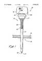
- FIG. 1is a perspective view of an embodiment of the obturator of the present invention shown inserted into a cannula to form a trocar assembly;
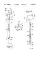
- FIG. 2is a side view of the obturator of FIG. 1 shown in the cutting position;
- FIG. 3is a bottom view of the obturator of FIG. 1;
- FIG. 4is a side view of the obturator of FIG. 1 rotated ninety degrees and shown in the safety position;
- FIG. 5is a sectional view of the obturator of FIG. 2;
- FIG. 6is a sectional view of the obturator of FIG. 4;
- FIG. 7is an enlarged partial sectional view of the obturator of FIG. 5;
- FIG. 8is an enlarged partial section view of the obturator of FIG. 6;
- FIG. 9is an exploded sectional view of the obturator of FIG. 1;
- FIG. 10is a partial perspective view of the distal end of the obturator shaft of FIG. 2;
- FIG. 11is a partial perspective view of the distal end of the obturator shaft of FIG. 4.
- FIG. 1an obturator according to the principles of the present invention is illustrated in FIG. 1 and designated by the reference numeral 10.
- the obturator 10is adapted for use with a trocar body 12, including a cannula 13, in order to form a penetrating trocar assembly 14.
- the obturator 10is first inserted through the trocar body 12, including the cannula 13, prior to being inserted through tissue forming a body wall 16, such as the abdominal wall.
- the purpose of the obturator 10is to create an incision by piercing, incising, cutting or otherwise penetrating the body wall 16 to allow the trocar body 12 to be left extending through the incision after the obturator 10 is removed.
- the trocar body 12, including the cannula 13,can then serve as an access port through the body wall 16 and into a body cavity 18.
- the obturator 10may comprise an elongate shaft 20 extending between a proximal end 22 and a distal end 24 along a longitudinal axis 26.
- the shaft 20includes an outer surface 27 which forms a cross section along its length and a tip 30 at the distal end 24.
- the outer surface 27is generally cylindrical about the axis 26 with a circular or similarly shaped cross section. This circular cross section may be advantageous when passing the shaft 20 through the trocar body 12 and the cannula 13 as shown in FIG. 1.
- the outer surface 27 of the shaft 20may also have a plurality of differing shaped cross sections as well as differing radial sizes.
- the shaft 20may include a plurality of shaft portions such as a first shaft portion 32 and a generally opposing second shaft portion 34.
- the first shaft portion 32may extend along the longitudinal axis 26 and terminate distally to form a first tip portion 35.
- this first tip portion 35includes a sharp distal tip 36.
- the second shaft portion 34may also extend along the longitudinal axis and terminates distally to form a second tip portion 37.
- this second tip portion 37includes a blunt distal tip 38.
- the shaft portions 32 and 34extend along the longitudinal axis 26 in juxtaposition to form at least a portion of the shaft 20.
- each of the shaft portions 32 and 34extends from the proximal end 22 to the distal end 24 of the shaft 20, where at least one of the first and second tip portions 35 and 37 defines the shaft tip 30.
- each of the portions of the shaft 32 and 34extend radially from an inner surface 40 to the outer surface 27.
- the inner surfaces 40may extend axially in juxtaposition to each other and be generally opposing and at least of portion of the inner surfaces 40 may be aligned along the longitudinal axis 26. In this configuration, the shaft portions 32 and 34 together form outer surface 27 and thus, the cross section 28 of the shaft 20.
- At least one of the shaft portionsmay have a cross section with the general shape of a section of a circle or other similar shape.
- the first and second shaft portions 32 and 34may even be asymmetrical along a portion of their lengths. However, other shapes may also be used as well as additional shaft portions.
- the first shaft portion 32is configured to be longitudinally movable relative to the second shaft portion 34.
- the inner surfaces 40 on each of the shaft portions 32 and 34may be configured with an opposing planar section 42 or planar sections aligned with the longitudinal axis 26. These opposing planar sections 42 allow the inner surfaces 40 on each shaft portion to slidably move against each other.
- the first tip portion 35includes a first planar side 44 and the second tip portion 37 includes an opposing and generally co-planar second planar side 46.
- Each of the planar sides 44 and 46may be configured for slidable contact along the longitudinal axis 26. All of opposing planar sections 42 and opposing planar sides 44 and 46 may be configured for relatively frictionless sliding contact and may include a frictionless surface finish.
- the first shaft portion 32 and the second shaft portion 34may be configured so as to be longitudinally slidable against each other without moving radially apart.
- this configurationincludes coupling the shaft portions 32 and 34 together.
- the first shaft portion 32may include a proximally located bore 48 through which a proximal end 50 of the second shaft portion 34 slidably passes.
- the bore 48 and the proximal shaft portion end 50may be aligned along the longitudinal axis 26.
- the bore 48 and the proximal shaft portion end 50are preferably cylindrical, but this is not essential and other cross sectional shapes may also be used.
- a boremay be configured through the second shaft portion 34 or even through the overall shaft 20, with the first shaft portion 32 having a proximal shaft portion for passage through the bore.
- a slidable joint or other coupling meansmay also be used to maintain the first and second shaft portions 32 and 34 radially together.
- one of the inner surfaces 40may include a longitudinal section having a tongue configuration.
- the opposing inner surface 40may comprise a longitudinal section having a grooved configuration for slidably containing the tongue.
- Other means for retaining the shaft portions radially togethermay include a sleeve ring which surrounds a portion of the shaft 20.
- the sleeve ringshould have a very limited axial length and be disposed along a proximal portion 22 of the shaft 20.
- the sleeve ringmust not surround the tip portions 35 and 37.
- other configurations and devicesmay also be used.
- a blade 52 having a first major surface 54 and a second major surface 56may be coupled to the first shaft portion 32 and particularly, to the first tip portion 35 to define the sharp distal tip 36.
- the blade 52may be a generally flat member with the major surfaces 54 and 56 being generally parallel to each other and to the longitudinal axis 26.
- the second major surface 54is directly attached to the first tip portion 35 to fixedly connect the blade 52 with the first shaft portion 32. This connection may be accomplished with adhesives, fasteners or the like.
- the blade 52may be an integral part of the first tip portion 35.
- the first major surface 56may be a planar surface and may extend at least partially along the longitudinal axis of the shaft 26.
- the first major surface 54forms at least part of the planar side 44 of the first tip portion 35.
- the sharp distal tip 36may be configured through a bevel 58 which extends from a distal edge 57 of the second major surface 56 to a distal edge 55 of the distally extending first major surface 54.
- the beveled surface 58creates a sharp edge 36 which extends across the width of the first major surface 52.
- This sharp edge 36may extend across the full cross section 28 of the shaft 20 and may include a rounded triangular shape having progressively distal positions.
- An actuating mechanism 60may be connected to the proximal end 22 of the shaft 20 to facilitate the relative longitudinal movement of the first shaft portion 32 and the second shaft portion 34. This relative movement of the shaft portions 32 and 34 allows the configuration of the shaft tip 30 to be primarily dependent on whether the first tip portion 35 extends distally of the second tip portion 37 or alternatively, whether the second tip portion 37 extends distally of the first tip portion 35.
- the actuating mechanism 60may be coupled to either or both of the shaft portions 32 and 34 for the relative movement therebetween. However, the actuating mechanism 60 may preferably be coupled to the proximal end 50 of the second shaft portion 34 and configured to allow movement of the second tip portion 37. This configuration maintains the first shaft portion 32 as a fixed shaft portion and allows the second shaft portion 34 to be a movable shaft portion.
- the first shaft portion 32may preferably be the fixed shaft portion due to the potentially high relative mass of the blade 52.
- the actuating mechanism 60may be configured for axially moving the first and second shaft portions 32 and 34 between a first, or cutting position 62 and a second, or safety position 64.
- the actuating mechanism 60may be coupled with a shaft block 65 which is coupled to the second shaft portion 34. Movement of the shaft block 65 by the actuating mechanism 60 moves the second shaft portion between the cutting and safety positions 62 and 64.
- a lockmay be provided within the actuating mechanism 60 for securing the obturator 10 in the safety position 64 once resistance is sensed against the first shaft portion 32.
- the actuating mechanism 60may be constructed in the accordance with the disclosure of U.S. Pat. No. 5,599,347, which issued Feb. 4, 1997, and which is fully incorporated herein by reference.
- the actuating mechanism 60may also include an actuator 70 for arming the obturator 10 such that the distal end 24 of the shaft 20 may be moved from the safety position 64 to the cutting position 62.
- the actuator 70may be a handle or similar device which extends outwardly from a housing 72 that surrounds the actuating mechanism 60.
- the actuator 70may be coupled with a release mechanism 74 which is adapted to mechanically release the lock securing the second shaft portion 34 in the safety position 64.
- the second shaft portion 34is moved proximally relative to the first shaft portion 32. This movement retracts the second tip portion 37 proximally of the first tip portion 35 to expose a sharp configuration and particularly, to expose the sharp distal tip 36.
- the cutting position 62facilitates the piercing or otherwise cutting of the body wall 16 by the shaft tip 30 at the distal end 24 of the shaft 20.
- the second shaft portion 34is moved distally relative to the first shaft portion 32. This movement extends the second tip portion 37 distally of the first tip portion 35 until the blunt distal end 38 covers and blocks any access to the sharp distal tip 36.
- the blunt distal tip 38has a generally rounded and blunt outer configuration with a flat inner surface 66 aligned with the second planer surface 46.
- the flat inner surface 66is coplanar with and comprises at least part of the second planar side 46. This allows the blunt distal tip 38 to axially slide against the opposing planer first major surface of the blade 52 between the cutting position 62 and the safety position 64.
- the safety position 64inhibits the cutting of the body wall 26 or any other tissue by providing a blunt shaft tip 30 and by covering and thus, shielding the sharp edge of the sharp distal tip 36.
- a biasing element 76may be coupled to the first and second shaft portions 32 and 34 for biasing the second shaft portion 34 to the second or safety position 64. This allows the obturator 10 to normally be in the safety position 64 and prevents inadvertent cutting, contamination or damage.
- the biasing elementmay be a spring which couples the first shaft portion 32 to the second shaft portion 34.
- the spring 76may be maintained in compression to maintain a constant pressure directed distally against the second shaft portion 34, as best illustrated in FIG. 7. When the obturator 10 is in the cutting position, the second shaft portion 34 is moved proximally and the spring 76 is further compressed.
- This compressionresults in additional force being directed by the biasing element 76 in an effort to move the obturator 10 into the safety position, as best illustrated in FIG. 8.
- This increased biasing forceadvantageously results in a quicker transition time from the cutting position 62 to the safety position 64.
- the provided obturator 10may include a shaft 20 having a longitudinal axis 26 and an outer surface 27 which extends between a proximal end 22 and a distal end 24.
- the shaft 20includes a first shaft portion 32 which defines part of the outer surface 27 and has a first inner surface 44.
- the first shaft portion 32extends distally to a sharp distal tip 36.
- the shaft 20also includes a second shaft portion 34, which also defines part of the outer surface 27 and includes a second inner surface 46.
- the second shaft portion 34extends distally to a distal tip 38 having a rounded blunt configuration and a blunt distal edge 39.
- Each of the inner surfaces 44 and 46may be formed to include a portion of the longitudinal axis 26.
- An actuating mechanismmay be coupled to the shaft 20 to facilitate the axially movement of the first shaft portion 32 relative to the second shaft portion 34 and between a first or cutting position 62 wherein the shaft tip 30 is characterized by the sharp distal tip 36 and a second or safety position 64 wherein the shaft tip is characterized by the blunt distal tip 38.
- the obturator 10may be inserted into a trocar body 12 and through a cannula 13 until the distal end 24 of the shaft 20 extends distally through the cannula.
- the actuating mechanism 60may be actuated or otherwise armed. When armed, the obturator 10 allows relative axial movement between the shaft portions 32 and 34 and between the cutting and safety positions 62 and 64. More specifically, arming the actuating mechanism 60 releases the lock securing the obturator 10 in the safety position 64 and allows the second shaft portion 34 to be moved proximally to expose the sharp distal tip 36 on the first shaft portion 32.
- the shaft tip 30may be pushed against the body wall 16.
- the resistive pressure of the body wall 16may be used to move the second shaft portion 34 proximally and exposes the sharp distal tip 36 which punctures or otherwise penetrates the body wall.
- the second shaft portion 34may be manually moved proximally and into the cutting position 62 to expose the sharp distal tip 36.
- the second tip portion 37is disposed in the cutting position 62 when the first tip portion 35 initially contacts the body wall.
- This biasingmay include sliding the blunt distal tip 38 along the inner surface 44 of the first shaft portion 32 until the blunt edge 39 slides distally of and covers the sharp distal tip 36. This prevents access to the sharp edge of the sharp distal tip 36 and prevents further cutting within the body cavity 18.
- the step of moving the second shaft portion 34may include moving the second shaft portion 34 in proximity to the inner surface 44 on the first shaft portion 32 between the cutting position 62 and the safety position 64. Preferably, this movement comprises sliding the second shaft portion 34 axially along the inner surface 44 of the first shaft portion 32.
Landscapes
- Health & Medical Sciences (AREA)
- Surgery (AREA)
- Life Sciences & Earth Sciences (AREA)
- Biomedical Technology (AREA)
- Nuclear Medicine, Radiotherapy & Molecular Imaging (AREA)
- Engineering & Computer Science (AREA)
- Pathology (AREA)
- Heart & Thoracic Surgery (AREA)
- Medical Informatics (AREA)
- Molecular Biology (AREA)
- Animal Behavior & Ethology (AREA)
- General Health & Medical Sciences (AREA)
- Public Health (AREA)
- Veterinary Medicine (AREA)
- Surgical Instruments (AREA)
Abstract
Description
Claims (11)
Priority Applications (1)
| Application Number | Priority Date | Filing Date | Title |
|---|---|---|---|
| US08/949,123US5916232A (en) | 1997-10-10 | 1997-10-10 | Asymmetrical obturator |
Applications Claiming Priority (1)
| Application Number | Priority Date | Filing Date | Title |
|---|---|---|---|
| US08/949,123US5916232A (en) | 1997-10-10 | 1997-10-10 | Asymmetrical obturator |
Publications (1)
| Publication Number | Publication Date |
|---|---|
| US5916232Atrue US5916232A (en) | 1999-06-29 |
Family
ID=25488624
Family Applications (1)
| Application Number | Title | Priority Date | Filing Date |
|---|---|---|---|
| US08/949,123Expired - LifetimeUS5916232A (en) | 1997-10-10 | 1997-10-10 | Asymmetrical obturator |
Country Status (1)
| Country | Link |
|---|---|
| US (1) | US5916232A (en) |
Cited By (77)
| Publication number | Priority date | Publication date | Assignee | Title |
|---|---|---|---|---|
| US20020161387A1 (en)* | 2000-06-22 | 2002-10-31 | Blanco Ernesto E. | Safety trocar with progressive cutting tip guards and gas jet tissue deflector |
| US20030045834A1 (en)* | 2001-08-31 | 2003-03-06 | Conmed Corporation | Obturator and cannula for a trocar adapted for ease of insertion and removal |
| GB2390544A (en)* | 2002-06-25 | 2004-01-14 | Michael Harold Jones | Surgical needle holder |
| US20040049100A1 (en)* | 1999-10-14 | 2004-03-11 | Atropos Limited | Retractor |
| US20040133555A1 (en)* | 1998-12-04 | 2004-07-08 | Toong Hoo-Min | Systems and methods for organizing data |
| USD499484S1 (en) | 2003-08-12 | 2004-12-07 | Erblan Surgical, Inc. | Trocar seal-valve |
| US20050209623A1 (en)* | 2004-03-02 | 2005-09-22 | Patton Michael T | Surgical obturator |
| US20050251190A1 (en)* | 2000-05-16 | 2005-11-10 | Mcfarlane Richard H | Penetrating tip for trocar assembly |
| US20050261661A1 (en)* | 2002-04-26 | 2005-11-24 | Mcfarlane Richard H | Floating seal assembly for a trocar |
| US20060030870A1 (en)* | 2004-08-03 | 2006-02-09 | Staudner Rupert A | Trocar with retractable cutting surface |
| USD517694S1 (en) | 2003-08-12 | 2006-03-21 | Erblan Surgical, Inc | Tip portion of an infusor |
| USD518177S1 (en) | 2002-03-08 | 2006-03-28 | Erblan Surgical, Inc. | Safety trocar with progressive cutting tip guards and gas jet tissue deflector |
| US20060247498A1 (en)* | 1998-12-01 | 2006-11-02 | Frank Bonadio | Instrument access device |
| US20060247499A1 (en)* | 1998-12-01 | 2006-11-02 | John Butler | Apparatus for inserting a surgical device at least partially through a wond opening |
| US20070004968A1 (en)* | 1998-12-01 | 2007-01-04 | Frank Bonadio | Seal for a cannula |
| US20070260275A1 (en)* | 2006-05-03 | 2007-11-08 | Applied Medical Resources Corporation | Flat blade shielded obturator |
| US7300399B2 (en) | 1998-12-01 | 2007-11-27 | Atropos Limited | Surgical device for retracting and/or sealing an incision |
| USD561338S1 (en)* | 2004-12-06 | 2008-02-05 | Erblan Surgical, Inc. | Trocar and trocar actuation mechanism |
| US20080051739A1 (en)* | 2006-08-25 | 2008-02-28 | Mcfarlane Richard H | Caged floating seal assembly |
| US20080228214A1 (en)* | 2006-05-03 | 2008-09-18 | Applied Medical Resources Corporation | Shield lockout for bladed obturator and trocars |
| US20080281344A1 (en)* | 2005-03-08 | 2008-11-13 | Vitalitec International, Inc. | Safety Trocar With Lancet Feature |
| US20080300617A1 (en)* | 2007-06-01 | 2008-12-04 | Tyco Healthcare Group Lp | Obturator tips |
| US20090082735A1 (en)* | 2006-03-27 | 2009-03-26 | Aesculap Ag | Surgical sealing element, surgical seal, and surgical sealing system |
| US20090093833A1 (en)* | 2007-10-05 | 2009-04-09 | Tyco Healthcare Group Lp | Bladeless obturator for use in a surgical trocar assembly |
| US7540839B2 (en) | 1999-10-14 | 2009-06-02 | Atropos Limited | Wound retractor |
| US7559893B2 (en) | 1998-12-01 | 2009-07-14 | Atropos Limited | Wound retractor device |
| US20100010446A1 (en)* | 2008-07-09 | 2010-01-14 | Aesculap Ag | Surgical sealing element holder for holding a surgical sealing element and surgical sealing system |
| US20100016799A1 (en)* | 2008-07-09 | 2010-01-21 | Aesculap Ag | Surgical protection device for a surgical sealing element and surgical sealing system |
| US20100063450A1 (en)* | 2007-04-18 | 2010-03-11 | Tyco Healthcare Group Lp | Trocar assembly with obturator dissector |
| US20100076478A1 (en)* | 2006-12-15 | 2010-03-25 | Smith Robert C | Trocar assembly with obturator design |
| US20100318112A1 (en)* | 2007-02-21 | 2010-12-16 | Smith Robert C | Obturator tips |
| US7867164B2 (en) | 1999-10-14 | 2011-01-11 | Atropos Limited | Wound retractor system |
| US20110040149A1 (en)* | 2007-01-12 | 2011-02-17 | Smith Robert C | Obturator assembly |
| US20110152910A1 (en)* | 2009-12-17 | 2011-06-23 | Tyco Healthcare Group Lp | Visual obturator with tip openings |
| US20110152753A1 (en)* | 2009-12-17 | 2011-06-23 | Tyco Healthcare Group Lp | Obturator tip |
| US8016755B2 (en) | 2000-10-19 | 2011-09-13 | Applied Medical Resources Corporation | Surgical access apparatus and method |
| US8021296B2 (en) | 1999-12-01 | 2011-09-20 | Atropos Limited | Wound retractor |
| US8109873B2 (en) | 2007-05-11 | 2012-02-07 | Applied Medical Resources Corporation | Surgical retractor with gel pad |
| USD655005S1 (en)* | 2010-09-21 | 2012-02-28 | Tyco Healthcare Group Lp | Bladeless obturator member |
| US8157835B2 (en) | 2001-08-14 | 2012-04-17 | Applied Medical Resouces Corporation | Access sealing apparatus and method |
| US8187177B2 (en) | 2003-09-17 | 2012-05-29 | Applied Medical Resources Corporation | Surgical instrument access device |
| US8187178B2 (en) | 2007-06-05 | 2012-05-29 | Atropos Limited | Instrument access device |
| US8226552B2 (en) | 2007-05-11 | 2012-07-24 | Applied Medical Resources Corporation | Surgical retractor |
| US8235054B2 (en) | 2002-06-05 | 2012-08-07 | Applied Medical Resources Corporation | Wound retractor |
| US8262568B2 (en) | 2008-10-13 | 2012-09-11 | Applied Medical Resources Corporation | Single port access system |
| US8267858B2 (en) | 2005-10-14 | 2012-09-18 | Applied Medical Resources Corporation | Wound retractor with gel cap |
| US8343047B2 (en) | 2008-01-22 | 2013-01-01 | Applied Medical Resources Corporation | Surgical instrument access device |
| US8375955B2 (en) | 2009-02-06 | 2013-02-19 | Atropos Limited | Surgical procedure |
| US8388526B2 (en) | 2001-10-20 | 2013-03-05 | Applied Medical Resources Corporation | Wound retraction apparatus and method |
| US20130102843A1 (en)* | 2011-10-24 | 2013-04-25 | Gerald Feuer | Jawed trocar assembly |
| US8657740B2 (en) | 2007-06-05 | 2014-02-25 | Atropos Limited | Instrument access device |
| US8703034B2 (en) | 2001-08-14 | 2014-04-22 | Applied Medical Resources Corporation | Method of making a tack-free gel |
| US8734336B2 (en) | 1998-12-01 | 2014-05-27 | Atropos Limited | Wound retractor device |
| US8758236B2 (en) | 2011-05-10 | 2014-06-24 | Applied Medical Resources Corporation | Wound retractor |
| US8821526B2 (en) | 2010-11-11 | 2014-09-02 | Specialtycare, Inc. | Trocar |
| US8932214B2 (en) | 2003-02-25 | 2015-01-13 | Applied Medical Resources Corporation | Surgical access system |
| US8961552B2 (en) | 2010-09-21 | 2015-02-24 | Covidien Lp | Bladeless obturators and bladeless obturator members |
| CN104540440A (en)* | 2011-10-24 | 2015-04-22 | 特罗凯尔有限责任公司 | Jawed trocar tip assembly |
| US9101315B2 (en) | 2010-11-11 | 2015-08-11 | Specialty Care, Inc. | Cannula system |
| US9186173B2 (en) | 2012-04-27 | 2015-11-17 | Specialty Care, Inc. | Optical obturator system |
| US9271753B2 (en) | 2002-08-08 | 2016-03-01 | Atropos Limited | Surgical device |
| US9289200B2 (en) | 2010-10-01 | 2016-03-22 | Applied Medical Resources Corporation | Natural orifice surgery system |
| US9289115B2 (en) | 2010-10-01 | 2016-03-22 | Applied Medical Resources Corporation | Natural orifice surgery system |
| US9351759B2 (en) | 2007-06-05 | 2016-05-31 | Atropos Limited | Instrument access device |
| US9642608B2 (en) | 2014-07-18 | 2017-05-09 | Applied Medical Resources Corporation | Gels having permanent tack free coatings and method of manufacture |
| US9949730B2 (en) | 2014-11-25 | 2018-04-24 | Applied Medical Resources Corporation | Circumferential wound retraction with support and guidance structures |
| US10172641B2 (en) | 2014-08-15 | 2019-01-08 | Applied Medical Resources Corporation | Natural orifice surgery system |
| WO2019046940A1 (en)* | 2017-09-06 | 2019-03-14 | Xpan Inc. | Radially expandable cannula system |
| CN109984780A (en)* | 2017-12-31 | 2019-07-09 | 江苏风和医疗器材股份有限公司 | A kind of sheath assembly |
| US10368908B2 (en) | 2015-09-15 | 2019-08-06 | Applied Medical Resources Corporation | Surgical robotic access system |
| US10575840B2 (en) | 2015-10-07 | 2020-03-03 | Applied Medical Resources Corporation | Wound retractor with multi-segment outer ring |
| US10674896B2 (en) | 2016-09-12 | 2020-06-09 | Applied Medical Resources Corporation | Surgical robotic access system for irregularly shaped robotic actuators and associated robotic surgical instruments |
| US11337727B2 (en) | 2020-03-13 | 2022-05-24 | Xpan Inc. | Radially expandable cannula devices, and systems and methods for using them |
| EP3833279A4 (en)* | 2018-08-10 | 2022-08-10 | Suremka, Llc | Surgical devices and deployment apparatuses |
| US11471142B2 (en) | 2013-03-15 | 2022-10-18 | Applied Medical Resources Corporation | Mechanical gel surgical access device |
| US20230130240A1 (en)* | 2021-10-21 | 2023-04-27 | OttoSurgical Instruments LLC | Trocar Device and System and Method for Monitoring Navigation of the Trocar Device |
| WO2023176531A1 (en)* | 2022-03-18 | 2023-09-21 | テルモ株式会社 | Lymphangiogenesis-inducing device |
Citations (20)
| Publication number | Priority date | Publication date | Assignee | Title |
|---|---|---|---|---|
| US5275583A (en)* | 1992-10-05 | 1994-01-04 | Lawrence Crainich | Trocar assembly with independently acting shield means |
| US5314417A (en)* | 1992-12-22 | 1994-05-24 | Ethicon, Inc. | Safety trocar |
| US5318580A (en)* | 1990-09-11 | 1994-06-07 | Origin Medsystems, Inc. | Retractable trocar |
| US5364372A (en)* | 1993-03-29 | 1994-11-15 | Endoscopic Concepts, Inc. | Trocar and cannula |
| US5417705A (en)* | 1993-05-14 | 1995-05-23 | Habley Medical Technology Corp. | Obturator with rotating, resettable safety shield |
| US5431635A (en)* | 1990-12-18 | 1995-07-11 | Yoon; Inbae | Safety penetrating instrument having a triggered safety member for establishing an endoscopic portal in an anatomical cavity wall |
| US5441041A (en)* | 1993-09-13 | 1995-08-15 | United States Surgical Corporation | Optical trocar |
| US5441513A (en)* | 1992-03-12 | 1995-08-15 | United States Surgical Corporation | Retracting tip trocar assembly |
| US5445142A (en)* | 1994-03-15 | 1995-08-29 | Ethicon Endo-Surgery, Inc. | Surgical trocars having optical tips defining one or more viewing ports |
| US5467762A (en)* | 1993-09-13 | 1995-11-21 | United States Surgical Corporation | Optical trocar |
| EP0701799A1 (en)* | 1994-08-25 | 1996-03-20 | Ethicon Endo-Surgery, Inc. | Safety trocar |
| US5554137A (en)* | 1993-10-08 | 1996-09-10 | United States Surgical Corporation | Tissue piercing members |
| US5554167A (en)* | 1993-10-08 | 1996-09-10 | United States Surgical Corporation | Tissue piercing members |
| US5569288A (en)* | 1990-12-18 | 1996-10-29 | Yoon; Inbae | Safety penetrating instrument |
| US5569292A (en)* | 1995-02-01 | 1996-10-29 | Ethicon Endo-Surgery, Inc. | Surgical penetration instrument with transparent blades and tip cover |
| US5569291A (en)* | 1995-02-01 | 1996-10-29 | Ethicon Endo-Surgery, Inc. | Surgical penetration and dissection instrument |
| US5591186A (en)* | 1991-05-22 | 1997-01-07 | Wurster; Helmut | Self-cutting trocar |
| US5599347A (en)* | 1991-02-13 | 1997-02-04 | Applied Medical Resources Corporation | Surgical trocar with cutoff circuit |
| US5607440A (en)* | 1994-05-06 | 1997-03-04 | Endoscopic Concepts, Inc. | Trocar with lockable shield |
| US5609604A (en)* | 1995-10-16 | 1997-03-11 | Ethicon Endo-Surgery, Inc. | Trocar with improved blade attachment |
- 1997
- 1997-10-10USUS08/949,123patent/US5916232A/ennot_activeExpired - Lifetime
Patent Citations (22)
| Publication number | Priority date | Publication date | Assignee | Title |
|---|---|---|---|---|
| US5318580A (en)* | 1990-09-11 | 1994-06-07 | Origin Medsystems, Inc. | Retractable trocar |
| US5431635A (en)* | 1990-12-18 | 1995-07-11 | Yoon; Inbae | Safety penetrating instrument having a triggered safety member for establishing an endoscopic portal in an anatomical cavity wall |
| US5569288A (en)* | 1990-12-18 | 1996-10-29 | Yoon; Inbae | Safety penetrating instrument |
| US5599347A (en)* | 1991-02-13 | 1997-02-04 | Applied Medical Resources Corporation | Surgical trocar with cutoff circuit |
| US5591186A (en)* | 1991-05-22 | 1997-01-07 | Wurster; Helmut | Self-cutting trocar |
| US5441513A (en)* | 1992-03-12 | 1995-08-15 | United States Surgical Corporation | Retracting tip trocar assembly |
| US5275583A (en)* | 1992-10-05 | 1994-01-04 | Lawrence Crainich | Trocar assembly with independently acting shield means |
| US5314417A (en)* | 1992-12-22 | 1994-05-24 | Ethicon, Inc. | Safety trocar |
| US5364372A (en)* | 1993-03-29 | 1994-11-15 | Endoscopic Concepts, Inc. | Trocar and cannula |
| US5417705A (en)* | 1993-05-14 | 1995-05-23 | Habley Medical Technology Corp. | Obturator with rotating, resettable safety shield |
| US5441041A (en)* | 1993-09-13 | 1995-08-15 | United States Surgical Corporation | Optical trocar |
| US5467762A (en)* | 1993-09-13 | 1995-11-21 | United States Surgical Corporation | Optical trocar |
| US5569160A (en)* | 1993-09-13 | 1996-10-29 | United States Surgical Corporation | Optical trocar |
| US5554167A (en)* | 1993-10-08 | 1996-09-10 | United States Surgical Corporation | Tissue piercing members |
| US5554137A (en)* | 1993-10-08 | 1996-09-10 | United States Surgical Corporation | Tissue piercing members |
| US5445142A (en)* | 1994-03-15 | 1995-08-29 | Ethicon Endo-Surgery, Inc. | Surgical trocars having optical tips defining one or more viewing ports |
| US5607440A (en)* | 1994-05-06 | 1997-03-04 | Endoscopic Concepts, Inc. | Trocar with lockable shield |
| EP0701799A1 (en)* | 1994-08-25 | 1996-03-20 | Ethicon Endo-Surgery, Inc. | Safety trocar |
| US5690663A (en)* | 1994-08-25 | 1997-11-25 | Ethicon Endo-Surgery Inc. | Safety trocar |
| US5569291A (en)* | 1995-02-01 | 1996-10-29 | Ethicon Endo-Surgery, Inc. | Surgical penetration and dissection instrument |
| US5569292A (en)* | 1995-02-01 | 1996-10-29 | Ethicon Endo-Surgery, Inc. | Surgical penetration instrument with transparent blades and tip cover |
| US5609604A (en)* | 1995-10-16 | 1997-03-11 | Ethicon Endo-Surgery, Inc. | Trocar with improved blade attachment |
Cited By (175)
| Publication number | Priority date | Publication date | Assignee | Title |
|---|---|---|---|---|
| US10278688B2 (en) | 1998-12-01 | 2019-05-07 | Atropos Limited | Wound retractor device |
| US9301808B2 (en) | 1998-12-01 | 2016-04-05 | Atropos Limited | Apparatus for inserting a surgical device at least partially through a wound opening |
| US9700296B2 (en) | 1998-12-01 | 2017-07-11 | Atropos Limited | Wound retractor device |
| US7559893B2 (en) | 1998-12-01 | 2009-07-14 | Atropos Limited | Wound retractor device |
| US20060247498A1 (en)* | 1998-12-01 | 2006-11-02 | Frank Bonadio | Instrument access device |
| US9757110B2 (en) | 1998-12-01 | 2017-09-12 | Atropos Limited | Instrument access device |
| US9095300B2 (en) | 1998-12-01 | 2015-08-04 | Atropos Limited | Wound retractor device |
| US8888693B2 (en) | 1998-12-01 | 2014-11-18 | Atropos Limited | Instrument access device |
| US8317691B2 (en) | 1998-12-01 | 2012-11-27 | Atropos Limited | Wound retractor device |
| US8465494B2 (en) | 1998-12-01 | 2013-06-18 | Atropos Limited | Apparatus for inserting a surgical device at least partially through a wound opening |
| US7998068B2 (en) | 1998-12-01 | 2011-08-16 | Atropos Limited | Instrument access device |
| US8734336B2 (en) | 1998-12-01 | 2014-05-27 | Atropos Limited | Wound retractor device |
| US20060247499A1 (en)* | 1998-12-01 | 2006-11-02 | John Butler | Apparatus for inserting a surgical device at least partially through a wond opening |
| US7300399B2 (en) | 1998-12-01 | 2007-11-27 | Atropos Limited | Surgical device for retracting and/or sealing an incision |
| US20070004968A1 (en)* | 1998-12-01 | 2007-01-04 | Frank Bonadio | Seal for a cannula |
| US20040133555A1 (en)* | 1998-12-04 | 2004-07-08 | Toong Hoo-Min | Systems and methods for organizing data |
| US7445597B2 (en) | 1999-10-14 | 2008-11-04 | Atropos Limited | Retractor |
| US7540839B2 (en) | 1999-10-14 | 2009-06-02 | Atropos Limited | Wound retractor |
| US20040049100A1 (en)* | 1999-10-14 | 2004-03-11 | Atropos Limited | Retractor |
| US7867164B2 (en) | 1999-10-14 | 2011-01-11 | Atropos Limited | Wound retractor system |
| US9277908B2 (en) | 1999-10-14 | 2016-03-08 | Atropos Limited | Retractor |
| US8740785B2 (en) | 1999-10-14 | 2014-06-03 | Atropos Limited | Wound retractor system |
| US8986202B2 (en) | 1999-10-14 | 2015-03-24 | Atropos Limited | Retractor |
| US8021296B2 (en) | 1999-12-01 | 2011-09-20 | Atropos Limited | Wound retractor |
| US8657741B2 (en) | 1999-12-01 | 2014-02-25 | Atropos Limited | Wound retractor |
| US20050251190A1 (en)* | 2000-05-16 | 2005-11-10 | Mcfarlane Richard H | Penetrating tip for trocar assembly |
| US8398666B2 (en)* | 2000-05-16 | 2013-03-19 | Teleflex Medical Incorporated | Penetrating tip for trocar assembly |
| US20020161387A1 (en)* | 2000-06-22 | 2002-10-31 | Blanco Ernesto E. | Safety trocar with progressive cutting tip guards and gas jet tissue deflector |
| US8105234B2 (en) | 2000-10-19 | 2012-01-31 | Applied Medical Resources Corporation | Surgical access apparatus and method |
| US8070676B2 (en) | 2000-10-19 | 2011-12-06 | Applied Medical Resources Corporation | Surgical access apparatus and method |
| US8496581B2 (en) | 2000-10-19 | 2013-07-30 | Applied Medical Resources Corporation | Surgical access apparatus and method |
| US8911366B2 (en) | 2000-10-19 | 2014-12-16 | Applied Medical Resources Corporation | Surgical access apparatus and method |
| US8672839B2 (en) | 2000-10-19 | 2014-03-18 | Applied Medical Resource Corporation | Surgical access apparatus and method |
| US8016755B2 (en) | 2000-10-19 | 2011-09-13 | Applied Medical Resources Corporation | Surgical access apparatus and method |
| US8870904B2 (en) | 2001-08-14 | 2014-10-28 | Applied Medical Resources Corporation | Access sealing apparatus and method |
| US9669153B2 (en) | 2001-08-14 | 2017-06-06 | Applied Medical Resources Corporation | Method of manufacturing a tack-free gel for a surgical device |
| US8157835B2 (en) | 2001-08-14 | 2012-04-17 | Applied Medical Resouces Corporation | Access sealing apparatus and method |
| US9878140B2 (en) | 2001-08-14 | 2018-01-30 | Applied Medical Resources Corporation | Access sealing apparatus and method |
| US8703034B2 (en) | 2001-08-14 | 2014-04-22 | Applied Medical Resources Corporation | Method of making a tack-free gel |
| US6989003B2 (en) | 2001-08-31 | 2006-01-24 | Conmed Corporation | Obturator and cannula for a trocar adapted for ease of insertion and removal |
| US20030045834A1 (en)* | 2001-08-31 | 2003-03-06 | Conmed Corporation | Obturator and cannula for a trocar adapted for ease of insertion and removal |
| US8388526B2 (en) | 2001-10-20 | 2013-03-05 | Applied Medical Resources Corporation | Wound retraction apparatus and method |
| USD518177S1 (en) | 2002-03-08 | 2006-03-28 | Erblan Surgical, Inc. | Safety trocar with progressive cutting tip guards and gas jet tissue deflector |
| US7011314B2 (en) | 2002-04-26 | 2006-03-14 | Taut, Inc. | Floating seal assembly for a trocar |
| US20050261661A1 (en)* | 2002-04-26 | 2005-11-24 | Mcfarlane Richard H | Floating seal assembly for a trocar |
| US10507017B2 (en) | 2002-06-05 | 2019-12-17 | Applied Medical Resources Corporation | Wound retractor |
| US9561024B2 (en) | 2002-06-05 | 2017-02-07 | Applied Medical Resources Corporation | Wound retractor |
| US8973583B2 (en) | 2002-06-05 | 2015-03-10 | Applied Medical Resources Corporation | Wound retractor |
| US8235054B2 (en) | 2002-06-05 | 2012-08-07 | Applied Medical Resources Corporation | Wound retractor |
| GB2390544A (en)* | 2002-06-25 | 2004-01-14 | Michael Harold Jones | Surgical needle holder |
| GB2390544B (en)* | 2002-06-25 | 2005-07-13 | Michael Harold Jones | Surgical needle holder |
| US9737335B2 (en) | 2002-08-08 | 2017-08-22 | Atropos Limited | Device |
| US9271753B2 (en) | 2002-08-08 | 2016-03-01 | Atropos Limited | Surgical device |
| US10405883B2 (en) | 2002-08-08 | 2019-09-10 | Atropos Limited | Surgical device |
| US9307976B2 (en) | 2002-10-04 | 2016-04-12 | Atropos Limited | Wound retractor |
| US9295459B2 (en) | 2003-02-25 | 2016-03-29 | Applied Medical Resources Corporation | Surgical access system |
| US8932214B2 (en) | 2003-02-25 | 2015-01-13 | Applied Medical Resources Corporation | Surgical access system |
| USD499484S1 (en) | 2003-08-12 | 2004-12-07 | Erblan Surgical, Inc. | Trocar seal-valve |
| USD517694S1 (en) | 2003-08-12 | 2006-03-21 | Erblan Surgical, Inc | Tip portion of an infusor |
| US8357086B2 (en) | 2003-09-17 | 2013-01-22 | Applied Medical Resources Corporation | Surgical instrument access device |
| US8187177B2 (en) | 2003-09-17 | 2012-05-29 | Applied Medical Resources Corporation | Surgical instrument access device |
| US20050209623A1 (en)* | 2004-03-02 | 2005-09-22 | Patton Michael T | Surgical obturator |
| US8066729B2 (en)* | 2004-03-02 | 2011-11-29 | Stryker Corporation | Surgical obturator |
| US20060030870A1 (en)* | 2004-08-03 | 2006-02-09 | Staudner Rupert A | Trocar with retractable cutting surface |
| US7419496B2 (en) | 2004-08-03 | 2008-09-02 | Staudner Rupert A | Trocar with retractable cutting surface |
| USD561338S1 (en)* | 2004-12-06 | 2008-02-05 | Erblan Surgical, Inc. | Trocar and trocar actuation mechanism |
| US8088137B2 (en)* | 2005-03-08 | 2012-01-03 | Michel Morisseau | Safety trocar with lancet feature |
| US20080281344A1 (en)* | 2005-03-08 | 2008-11-13 | Vitalitec International, Inc. | Safety Trocar With Lancet Feature |
| US8313431B2 (en) | 2005-10-14 | 2012-11-20 | Applied Medical Resources Corporation | Split hoop wound retractor |
| US9101354B2 (en) | 2005-10-14 | 2015-08-11 | Applied Medical Resources Corporation | Wound retractor with gel cap |
| US8308639B2 (en) | 2005-10-14 | 2012-11-13 | Applied Medical Resources Corporation | Split hoop wound retractor with gel pad |
| US8414487B2 (en) | 2005-10-14 | 2013-04-09 | Applied Medical Resources Corporation | Circular surgical retractor |
| US8267858B2 (en) | 2005-10-14 | 2012-09-18 | Applied Medical Resources Corporation | Wound retractor with gel cap |
| US9649102B2 (en) | 2005-10-14 | 2017-05-16 | Applied Medical Resources Corporation | Wound retractor with split hoops |
| US9017254B2 (en) | 2005-10-14 | 2015-04-28 | Applied Medical Resources Corporation | Hand access laparoscopic device |
| US8647265B2 (en) | 2005-10-14 | 2014-02-11 | Applied Medical Resources Corporation | Hand access laparoscopic device |
| US9474519B2 (en) | 2005-10-14 | 2016-10-25 | Applied Medical Resources Corporation | Hand access laparoscopic device |
| US20090082735A1 (en)* | 2006-03-27 | 2009-03-26 | Aesculap Ag | Surgical sealing element, surgical seal, and surgical sealing system |
| US7842014B2 (en) | 2006-03-27 | 2010-11-30 | Aesculap Ag | Surgical sealing element, surgical seal, and surgical sealing system |
| US9474548B2 (en) | 2006-05-03 | 2016-10-25 | Applied Medical Resources Corporation | Shield lockout for bladed obturator and trocars |
| US20080228214A1 (en)* | 2006-05-03 | 2008-09-18 | Applied Medical Resources Corporation | Shield lockout for bladed obturator and trocars |
| US8801741B2 (en) | 2006-05-03 | 2014-08-12 | Applied Medical Resources Corporation | Flat blade shielded obturator |
| US8657843B2 (en)* | 2006-05-03 | 2014-02-25 | Applied Medical Resources Corporation | Shield lockout for bladed obturator and trocars |
| US20070260275A1 (en)* | 2006-05-03 | 2007-11-08 | Applied Medical Resources Corporation | Flat blade shielded obturator |
| US10799267B2 (en) | 2006-08-25 | 2020-10-13 | Teleflex Medical Incorporated | Caged floating seal assembly |
| US9901373B2 (en) | 2006-08-25 | 2018-02-27 | Teleflex Medical Incorporated | Caged floating seal assembly |
| US7731695B2 (en) | 2006-08-25 | 2010-06-08 | Teleflex Medical Incorporated | Caged floating seal assembly |
| US20080051739A1 (en)* | 2006-08-25 | 2008-02-28 | Mcfarlane Richard H | Caged floating seal assembly |
| US8821445B2 (en) | 2006-08-25 | 2014-09-02 | Teleflex Medical Incorporated | Caged floating seal assembly |
| US20100241080A1 (en)* | 2006-08-25 | 2010-09-23 | Teleflex Medical Incorporated | Caged floating seal assembly |
| US20100076478A1 (en)* | 2006-12-15 | 2010-03-25 | Smith Robert C | Trocar assembly with obturator design |
| US8845670B2 (en) | 2006-12-15 | 2014-09-30 | Covidien Lp | Trocar assembly with obturator design |
| US20110040149A1 (en)* | 2007-01-12 | 2011-02-17 | Smith Robert C | Obturator assembly |
| US20100318112A1 (en)* | 2007-02-21 | 2010-12-16 | Smith Robert C | Obturator tips |
| US8348968B2 (en) | 2007-02-21 | 2013-01-08 | Covidien Lp | Obturator tips |
| US8956326B2 (en) | 2007-02-21 | 2015-02-17 | Covidien Lp | Obturator tips |
| US8940007B2 (en) | 2007-04-18 | 2015-01-27 | Covidien Lp | Trocar assembly with obturator dissector |
| US20100063450A1 (en)* | 2007-04-18 | 2010-03-11 | Tyco Healthcare Group Lp | Trocar assembly with obturator dissector |
| US8109873B2 (en) | 2007-05-11 | 2012-02-07 | Applied Medical Resources Corporation | Surgical retractor with gel pad |
| US8226552B2 (en) | 2007-05-11 | 2012-07-24 | Applied Medical Resources Corporation | Surgical retractor |
| US8961410B2 (en) | 2007-05-11 | 2015-02-24 | Applied Medical Resources Corporation | Surgical retractor with gel pad |
| US9028521B2 (en) | 2007-06-01 | 2015-05-12 | Covidien Lp | Obturator tips |
| US20080300617A1 (en)* | 2007-06-01 | 2008-12-04 | Tyco Healthcare Group Lp | Obturator tips |
| US10321934B2 (en) | 2007-06-05 | 2019-06-18 | Atropos Limited | Instrument access device |
| US10537360B2 (en) | 2007-06-05 | 2020-01-21 | Atropos Limited | Instrument access device |
| US8657740B2 (en) | 2007-06-05 | 2014-02-25 | Atropos Limited | Instrument access device |
| US8187178B2 (en) | 2007-06-05 | 2012-05-29 | Atropos Limited | Instrument access device |
| US9351759B2 (en) | 2007-06-05 | 2016-05-31 | Atropos Limited | Instrument access device |
| US9408597B2 (en) | 2007-06-05 | 2016-08-09 | Atropos Limited | Instrument access device |
| US8282663B2 (en) | 2007-10-05 | 2012-10-09 | Tyco Healthcare Group Lp | Bladeless obturator for use in a surgical trocar assembly |
| US9078698B2 (en) | 2007-10-05 | 2015-07-14 | Covidien Lp | Bladeless obturator for use in surgical trocar assembly |
| US20090093833A1 (en)* | 2007-10-05 | 2009-04-09 | Tyco Healthcare Group Lp | Bladeless obturator for use in a surgical trocar assembly |
| US8663267B2 (en) | 2007-10-05 | 2014-03-04 | Covidien Lp | Bladeless obturator for use in a surgical trocar assembly |
| US8343047B2 (en) | 2008-01-22 | 2013-01-01 | Applied Medical Resources Corporation | Surgical instrument access device |
| US20100016799A1 (en)* | 2008-07-09 | 2010-01-21 | Aesculap Ag | Surgical protection device for a surgical sealing element and surgical sealing system |
| US8246586B2 (en) | 2008-07-09 | 2012-08-21 | Aesculap Ag | Surgical sealing element holder for holding a surgical sealing element and surgical sealing system |
| US8696636B2 (en) | 2008-07-09 | 2014-04-15 | Aesculap Ag | Surgical sealing element holder for holding a surgical sealing element and surgical sealing system |
| US20100010446A1 (en)* | 2008-07-09 | 2010-01-14 | Aesculap Ag | Surgical sealing element holder for holding a surgical sealing element and surgical sealing system |
| US8137318B2 (en) | 2008-07-09 | 2012-03-20 | Aesculap Ag | Surgical protection device for a surgical sealing element and surgical sealing system |
| US8721537B2 (en) | 2008-10-13 | 2014-05-13 | Applied Medical Resources Corporation | Single port access system |
| US8480575B2 (en) | 2008-10-13 | 2013-07-09 | Applied Medical Resources Corporation | Single port access system |
| US8894571B2 (en) | 2008-10-13 | 2014-11-25 | Applied Medical Resources Corporation | Single port access system |
| US8262568B2 (en) | 2008-10-13 | 2012-09-11 | Applied Medical Resources Corporation | Single port access system |
| US8375955B2 (en) | 2009-02-06 | 2013-02-19 | Atropos Limited | Surgical procedure |
| US20160128727A1 (en)* | 2009-12-17 | 2016-05-12 | Covidien Lp | Visual obturator with tip openings |
| US9226774B2 (en)* | 2009-12-17 | 2016-01-05 | Covidien Lp | Visual obturator with tip openings |
| US9301778B2 (en) | 2009-12-17 | 2016-04-05 | Covidien Lp | Obturator tip |
| US20110152910A1 (en)* | 2009-12-17 | 2011-06-23 | Tyco Healthcare Group Lp | Visual obturator with tip openings |
| US20110152753A1 (en)* | 2009-12-17 | 2011-06-23 | Tyco Healthcare Group Lp | Obturator tip |
| US8979883B2 (en)* | 2009-12-17 | 2015-03-17 | Covidien Lp | Obturator tip |
| EP2335620A3 (en)* | 2009-12-17 | 2012-05-16 | Tyco Healthcare Group LP | Obturator tip |
| US10092321B2 (en) | 2010-09-21 | 2018-10-09 | Covidien Lp | Bladeless obturators and bladeless obturator members |
| USD655005S1 (en)* | 2010-09-21 | 2012-02-28 | Tyco Healthcare Group Lp | Bladeless obturator member |
| US8961552B2 (en) | 2010-09-21 | 2015-02-24 | Covidien Lp | Bladeless obturators and bladeless obturator members |
| US9289115B2 (en) | 2010-10-01 | 2016-03-22 | Applied Medical Resources Corporation | Natural orifice surgery system |
| US10376282B2 (en) | 2010-10-01 | 2019-08-13 | Applied Medical Resources Corporation | Natural orifice surgery system |
| US12089872B2 (en) | 2010-10-01 | 2024-09-17 | Applied Medical Resources Corporation | Natural orifice surgery system |
| US11123102B2 (en) | 2010-10-01 | 2021-09-21 | Applied Medical Resources Corporation | Natural orifice surgery system |
| US9872702B2 (en) | 2010-10-01 | 2018-01-23 | Applied Medical Resources Corporation | Natural orifice surgery system |
| US9289200B2 (en) | 2010-10-01 | 2016-03-22 | Applied Medical Resources Corporation | Natural orifice surgery system |
| US10271875B2 (en) | 2010-10-01 | 2019-04-30 | Applied Medical Resources Corporation | Natural orifice surgery system |
| US9101315B2 (en) | 2010-11-11 | 2015-08-11 | Specialty Care, Inc. | Cannula system |
| US8821526B2 (en) | 2010-11-11 | 2014-09-02 | Specialtycare, Inc. | Trocar |
| US9241697B2 (en) | 2011-05-10 | 2016-01-26 | Applied Medical Resources Corporation | Wound retractor |
| US8758236B2 (en) | 2011-05-10 | 2014-06-24 | Applied Medical Resources Corporation | Wound retractor |
| US9307975B2 (en) | 2011-05-10 | 2016-04-12 | Applied Medical Resources Corporation | Wound retractor |
| US9192366B2 (en) | 2011-05-10 | 2015-11-24 | Applied Medical Resources Corporation | Wound retractor |
| CN104540440A (en)* | 2011-10-24 | 2015-04-22 | 特罗凯尔有限责任公司 | Jawed trocar tip assembly |
| US9662133B2 (en) | 2011-10-24 | 2017-05-30 | Trocare Llc | Jawed tip assembly |
| US20130102843A1 (en)* | 2011-10-24 | 2013-04-25 | Gerald Feuer | Jawed trocar assembly |
| US8708889B2 (en)* | 2011-10-24 | 2014-04-29 | Trocare, LLC | Jawed trocar assembly |
| US9186173B2 (en) | 2012-04-27 | 2015-11-17 | Specialty Care, Inc. | Optical obturator system |
| US11471142B2 (en) | 2013-03-15 | 2022-10-18 | Applied Medical Resources Corporation | Mechanical gel surgical access device |
| US9642608B2 (en) | 2014-07-18 | 2017-05-09 | Applied Medical Resources Corporation | Gels having permanent tack free coatings and method of manufacture |
| US12262914B2 (en) | 2014-08-15 | 2025-04-01 | Applied Medical Resources Corporation | Natural orifice surgery system |
| US10172641B2 (en) | 2014-08-15 | 2019-01-08 | Applied Medical Resources Corporation | Natural orifice surgery system |
| US11583316B2 (en) | 2014-08-15 | 2023-02-21 | Applied Medical Resources Corporation | Natural orifice surgery system |
| US10952768B2 (en) | 2014-08-15 | 2021-03-23 | Applied Medical Resources Corporation | Natural orifice surgery system |
| US9949730B2 (en) | 2014-11-25 | 2018-04-24 | Applied Medical Resources Corporation | Circumferential wound retraction with support and guidance structures |
| US10368908B2 (en) | 2015-09-15 | 2019-08-06 | Applied Medical Resources Corporation | Surgical robotic access system |
| US11382658B2 (en) | 2015-09-15 | 2022-07-12 | Applied Medical Resources Corporation | Surgical robotic access system |
| US11883068B2 (en) | 2015-09-15 | 2024-01-30 | Applied Medical Resources Corporation | Surgical robotic access system |
| US10575840B2 (en) | 2015-10-07 | 2020-03-03 | Applied Medical Resources Corporation | Wound retractor with multi-segment outer ring |
| US12185932B2 (en) | 2015-10-07 | 2025-01-07 | Applied Medical Resources Corporation | Wound retractor with multi-segment outer ring |
| US11602338B2 (en) | 2015-10-07 | 2023-03-14 | Applied Medical Resources Corporation | Wound retractor with multi-segment outer ring |
| US10674896B2 (en) | 2016-09-12 | 2020-06-09 | Applied Medical Resources Corporation | Surgical robotic access system for irregularly shaped robotic actuators and associated robotic surgical instruments |
| US11627867B2 (en) | 2016-09-12 | 2023-04-18 | Applied Medical Resources Corporation | Surgical robotic access system for irregularly shaped robotic actuators and associated robotic surgical instruments |
| US11992184B2 (en) | 2016-09-12 | 2024-05-28 | Applied Medical Resources Corporation | Surgical robotic access system for irregularly shaped robotic actuators and associated robotic surgical instruments |
| US11576700B2 (en) | 2017-09-06 | 2023-02-14 | Xpan Inc. | Radially expandable cannula systems and methods for use |
| WO2019046940A1 (en)* | 2017-09-06 | 2019-03-14 | Xpan Inc. | Radially expandable cannula system |
| CN109984780A (en)* | 2017-12-31 | 2019-07-09 | 江苏风和医疗器材股份有限公司 | A kind of sheath assembly |
| EP3833279A4 (en)* | 2018-08-10 | 2022-08-10 | Suremka, Llc | Surgical devices and deployment apparatuses |
| US11337727B2 (en) | 2020-03-13 | 2022-05-24 | Xpan Inc. | Radially expandable cannula devices, and systems and methods for using them |
| US20230130240A1 (en)* | 2021-10-21 | 2023-04-27 | OttoSurgical Instruments LLC | Trocar Device and System and Method for Monitoring Navigation of the Trocar Device |
| WO2023176531A1 (en)* | 2022-03-18 | 2023-09-21 | テルモ株式会社 | Lymphangiogenesis-inducing device |
Similar Documents
| Publication | Publication Date | Title |
|---|---|---|
| US5916232A (en) | Asymmetrical obturator | |
| US8523895B2 (en) | Surgical obturator | |
| US5486190A (en) | Safety trocar | |
| US5674237A (en) | Safety trocar | |
| CA2156786C (en) | Safety trocar | |
| CA2377365C (en) | Safety trocar with progressive cutting tip guards and gas jet tissue deflector | |
| US5314417A (en) | Safety trocar | |
| AU2003225597B2 (en) | Safety trocar with progressive cutting tip guards and gas jet tissue deflector | |
| US5261891A (en) | Trocar | |
| US5904699A (en) | Trocar for penetration and skin incision | |
| US7419496B2 (en) | Trocar with retractable cutting surface | |
| US20040230155A1 (en) | Insufflator and method of use | |
| EP1605812A2 (en) | Insufflator and method of use | |
| EP1563797B1 (en) | Safety trocar with progressive cutting tip guards and gas jet tissue deflector | |
| CA2051499C (en) | Safety trocar |
Legal Events
| Date | Code | Title | Description |
|---|---|---|---|
| AS | Assignment | Owner name:APPLIED MEDICAL RESOURCES CORPORATION, CALIFORNIA Free format text:ASSIGNMENT OF ASSIGNORS INTEREST;ASSIGNOR:HART, CHARLES C.;REEL/FRAME:008865/0287 Effective date:19971010 | |
| STCF | Information on status: patent grant | Free format text:PATENTED CASE | |
| FPAY | Fee payment | Year of fee payment:4 | |
| FEPP | Fee payment procedure | Free format text:PAT HOLDER NO LONGER CLAIMS SMALL ENTITY STATUS, ENTITY STATUS SET TO UNDISCOUNTED (ORIGINAL EVENT CODE: STOL); ENTITY STATUS OF PATENT OWNER: LARGE ENTITY | |
| FPAY | Fee payment | Year of fee payment:8 | |
| FPAY | Fee payment | Year of fee payment:12 | |
| AS | Assignment | Owner name:CITIBANK, N.A., TEXAS Free format text:SECURITY AGREEMENT;ASSIGNOR:APPLIED MEDICAL RESOURCES CORPORATION;REEL/FRAME:028115/0276 Effective date:20120417 | |
| AS | Assignment | Owner name:JPMORGAN CHASE BANK, N.A., AS ADMINISTRATIVE AGENT, ILLINOIS Free format text:SECURITY INTEREST;ASSIGNOR:APPLIED MEDICAL RESOURCES CORPORATION;REEL/FRAME:042669/0725 Effective date:20170531 Owner name:JPMORGAN CHASE BANK, N.A., AS ADMINISTRATIVE AGENT Free format text:SECURITY INTEREST;ASSIGNOR:APPLIED MEDICAL RESOURCES CORPORATION;REEL/FRAME:042669/0725 Effective date:20170531 | |
| AS | Assignment | Owner name:APPLIED MEDICAL RESOURCES CORPORATION, CALIFORNIA Free format text:RELEASE BY SECURED PARTY;ASSIGNOR:JPMORGAN CHASE BANK, N.A.;REEL/FRAME:056751/0169 Effective date:20210625 | |
| AS | Assignment | Owner name:APPLIED MEDICAL RESOURCES CORPORATION, CALIFORNIA Free format text:RELEASE BY SECURED PARTY;ASSIGNOR:CITIBANK N.A., AS ADMINISTRATIVE AGENT;REEL/FRAME:066795/0595 Effective date:20240129 |