US5916166A - Medical guidewire with fully hardened core - Google Patents
Medical guidewire with fully hardened coreDownload PDFInfo
- Publication number
- US5916166A US5916166AUS08/752,714US75271496AUS5916166AUS 5916166 AUS5916166 AUS 5916166AUS 75271496 AUS75271496 AUS 75271496AUS 5916166 AUS5916166 AUS 5916166A
- Authority
- US
- United States
- Prior art keywords
- coil
- distal
- guidewire
- proximal
- extremity
- Prior art date
- Legal status (The legal status is an assumption and is not a legal conclusion. Google has not performed a legal analysis and makes no representation as to the accuracy of the status listed.)
- Expired - Lifetime
Links
Images


Classifications
- A—HUMAN NECESSITIES
- A61—MEDICAL OR VETERINARY SCIENCE; HYGIENE
- A61M—DEVICES FOR INTRODUCING MEDIA INTO, OR ONTO, THE BODY; DEVICES FOR TRANSDUCING BODY MEDIA OR FOR TAKING MEDIA FROM THE BODY; DEVICES FOR PRODUCING OR ENDING SLEEP OR STUPOR
- A61M25/00—Catheters; Hollow probes
- A61M25/01—Introducing, guiding, advancing, emplacing or holding catheters
- A61M25/09—Guide wires
- A61M2025/09175—Guide wires having specific characteristics at the distal tip
Definitions
- This inventionrelates to guidewires for use with interventional and diagnostic catheters and more particularly, to guidewires with a fully hardened core having the characteristic of superior torsional control or torque transmission.
- a guidewireis the initial member inserted into a body cavity during many transluminal procedures.
- a guidewireis an elongated fine wire device intended to readily pass through body passageways to a location at which a medical procedure or treatment is to take place. Thereafter, in a typical arrangement, a catheter is threaded over the thus inserted guidewire, with the catheter following the pathway defined by the guidewire.
- a guidewireis flexible, at least at its remote distal end tip.
- Remote distal end tip flexibilityis often enhanced by providing one or more fine coils at the distal portion of the guidewire and securing these coils to the distal end of the guidewire's core.
- this securement applicationalso includes a rounded distal tip that imparts some atraumatic characteristics to the guidewire.
- these componentsare secured together by soldering, brazing, welding or by using an adhesive such as ultraviolet-curing adhesives, catalytic-curing such as epoxy or anaerobic adhesives such as cyanoacrylate adhesives.
- Distally tapered guidewiresare generally composed of a stainless steel or austenitic metallic core which is not amendable to heat treatment for hardening the base metal.
- Stainless steel alloys employed in the medical fieldgenerally have a high chromium and low carbon content to provide resistance to oxidation and corrosion.
- Stainless steel or austenitic alloy guidewiresare amendable to work hardening but the final process yields a wire that is hardened primarily in the outer layers. Any hardness developed by the work process decreases or is totally absent as the center of the core is approached where it remains relatively soft.
- stainless steel or austenitic alloy guidewire coresare work hardened, they are distally tapered by standard diameter reduction processes, which exposes the relatively soft inner cross sectional layers and becomes the entire core of the distal end. This results in the stainless steel guidewire having inherently disportionate hardening throughout the length of the wire yielding suboptimal torsional characteristics. Inconsistent proximal to distal rotational movement makes it difficult for the clinician to penetrate small blood vessels while inadequate hardness affects the guidewire's catheter tracking capabilities. Stainless steel guidewires that suffer from inadequate entire cross sectional area hardening do not have high torsional capabilities for allowing the navigation through tortuous coronary, kidney or neurological vessels. In addition, such guidewires can suffer from snap or have unpredictable final tip positioning. Furthermore, it is important for a guidewire to be able to conform over sever curves and sharp angles without causing plastic deformation thereby having high ductility.
- the present inventionemploys martensitic alloys which are amendable to heat treatment that renders the core of a guidewire to become fully hardened throughout its entire cross sectional area.
- this inventionis tapered distally, the reduced diameter maintains the fully hardened characteristics rendering a guidewire that has a fully hardened core or mandrel from the proximal end throughout its longitudinal length to the distal tip.
- One advantage of this fully hardened, distally tapered, guidewireis that the relative torsion input generated at the proximal end is transmitted along the longitudinal length with the torsion output at the distal end virtually identical to the input. This is a desirable characteristic for a guidewire because it allows the clinician to predict the amount of distal tip rotation based on proximal torsional input while confirming the progress of this activity using a two dimensional fluoroscopy system.
- a guidewireit is important for a guidewire to have high ductility thereby allow it to conform over tortuous curves and sharp angles without causing plastic deformation.
- Thiscan be demonstrated on a standard stress-strain curve, where the characteristics of elasticity and plasticity usually result in a bilinear curve, with one line representing the elastic response and the other the plastic response, and the bend between the two lines the yield point at which further stress results in deformation of the material.
- a standard stress-strain curvewhere the characteristics of elasticity and plasticity usually result in a bilinear curve, with one line representing the elastic response and the other the plastic response, and the bend between the two lines the yield point at which further stress results in deformation of the material.
- light steel alloysdo not exhibit a clearly defined yield point. In such cases the yield strength is approximated by an offset method.
- the yield strengthis generally assumed to be that stress at which the material exhibits a permanent set of some constant value, such as 0.2% It has been demonstrated that the present invention exhibits a yield strength where the constant value at which a permanent set develops is substantially lower than 0.2%. Furthermore, in all standard stainless steel and austenitic alloy guidewires manufactured to date, the elasticity portion of the stress-strain curve is lower than that for the present invention at any given wire diameter. Therefore, the present invention has a significant advantage in that the yield strength is higher than the standard guidewire thereby having higher ductility for a given cross sectional area. These parameters translate into a guidewire which provides the clinician with a both a safer and higher performance design (e.g., ductility, catheter support, one-to-one torsion tranmission) then presently available.
- some constant valuesuch as 0.2%
- Another object of the inventionis to provide a guidewire of the above character that has high and consistent torsional capabilities.
- Another object of the present inventionis to provide a guidewire manufactured from a high ductility material thereby providing superior resistance to deformation when stressed over that of standard stainless steed guidewires.
- Another object of the present inventionis to provide a guide wire of the above character which is provided with a small tip facilitating deep penetration into small vessels.
- Another object of the present inventionis to provide a guide wire of the above character which has a relatively large proximal diameter to facilitate tracking of the catheter while it is in use.
- Another object of the present inventionis to provide a guide wire of the above character that has a very floppy distal end.
- Another object of the present inventionis to provide a guide wire of the above character that can be provided with various degrees of floppiness on its distal end.
- FIG. 1is a graphical depiction of the relative percent hardness throughout the cross sectional area of the core comparing that of a standard stainless steel with that of the present invention.
- FIG. 2is a graphical representation of the relative degree of hardness along the entire length of a standard stainless steel guidewire with a step-down tapered core.
- FIG. 3is a graphical representation of the relative degree of hardness along the entire length of the present invention with a step-down tapered core.
- FIG. 4is a graphical representation of the relative degree of hardness along the entire length of a standard stainless steel guidewire with a constant tapered core.
- FIG. 5is a graphical representation of the relative degree of hardness along the entire length of the present invention with a constant tapered core.
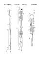
- FIG. 6is a side elevational view of the constant tapered core wire used in connection with construction of the fully hardened guidewire incorporating the present invention.
- FIG. 7is a side elevational view partially in cross section of a constant tapered guide wire incorporating the present invention which is provided with a floppy distal end having an attached round protrusion.
- FIG. 8is an enlarged view of the distal extremity of the guide wire shown in FIG. 7.
- FIG. 9is a side elevational view partially in cross section of a constant tapered guide wire incorporating the present invention which is provided with a floppy distal end having a detached round protrusion and safety wire.
- FIG. 10is an enlarged view of the distal extremity of the guide wire shown in FIG. 9.
- FIG. 11is a side elevational view of the step down tapered core wire used in connection with construction of the fully hardened guidewire incorporating the present invention.
- FIG. 12is a side elevational view partially in cross section of a step down tapered guide wire incorporating the present invention which is provided with a floppy distal end having an attached round protrusion.
- FIG. 13is a side elevational view partially in cross section of a step down tapered guide wire incorporating the present invention which is provided with a floppy distal end having a detached round protrusion and safety wire.
- the torsional guidewire with a fully hardened corecomprises an elongate core element having proximal and distal ends and having a decreasing cross sectional area in a direction toward the distal end. It is also comprised of one or more coils carried by and secured to the core element and extending over the distal extremity of the core element.
- the coilis formed of wire that is wound in a coil or helix configuration.
- a graphdepicts the relative percent hardness throughout the entire cross sectional area of a guidewire core or mandrel comparing a standard stainless steel guidewire 14 with the present invention 10.
- This graphrepresents a cross section of each wire diameter before either has been subjected to any tapering process.
- the present invention guidewire coreis tapered, the reduced cross section maintains the hardness throughout the length of the guidewire.
- the present inventionemploys a material that has a higher ductility and yield strength for a given wire diameter, and can be fully hardened throughout it cross section by heat-treatment.
- the heat treated, fully hard core of the present inventionsmaintains a constant hardness (H) throughout its longitudinal length regardless that the surface layers are removed during tapering processing to expose the inner core.
- the core element 12shown in more detail in FIG. 6, is formed of a suitable material such as one of the martensitic steel alloys.
- a suitable materialsuch as one of the martensitic steel alloys.
- the proximal portion 20with a relatively constant diameter throughout its entire length, a constant taper 22 and distal end portion 24.
- the core element 12has a suitable diameter ranging from 0.008 to 0.0199 inches and has a suitable length ranging from 100 to 300 centimeters.
- the core element 12is provided with proximal and distal ends 21 and 23, respectively.
- the core element 12is ground to provide a core wire that has a decreasing cross sectional area 22 in a direction toward the distal end.
- the core 12is provided with a cylindrical proximal portion 20 that extends over most of the length of the core.
- a tapered portion 22adjoins the proximal portion 20 and extends over a suitable distance ranging from 2 to 20 inches, with a preferred range of 4 to 15 inches.
- the remaining length of the core element 12is ground to a distal diameter ranging from 0.002 to 0.004 inches for a length of approximately 2 to 5 centimeters.
- the core element 12has been carefully dimensioned by grinding to provide a decreasing cross sectional area or a taper as hereinbefore described.
- guidewire 10may consist of one or two coils (36 and alternately 32) surrounding the core and attached near the distal end.
- Distal coil 36itself is shown in FIGS. 7 and 8 and is an important component of the guidewire 10.
- Distal coil 32functions to protect the small diameter distal section 24 of guidewire 10 from damage and maintain its floppy characteristics.
- Coil 36is wound from a suitable material such as gold/nickel alloy and has a diameter that ranges from 0.001 to 0.004 inches with a preferable diameter of 0.003 inches.
- the material of coil 36may also be selected from a wide range of metallic (e.g., gold, tantalum, tungsten, platinum, iridium, rhenium and alloys of the materials) or polymeric materials to meet a particular need.
- metallice.g., gold, tantalum, tungsten, platinum, iridium, rhenium and alloys of the materials
- a distal ball 38is formed on the distal end 23 of the core using a process that utilizes a portion of the distal coil 36 as material to form the ball 38 as hereinafter described.
- proximal coil 32Another core or coil section can be provided which is identified as proximal coil 32. As shown in FIG. 7, which details a dual coil design, the distal end of the proximal coil 32 abuts to the proximal end of distal coil 36. Proximal coil 32 surrounds the tapered core 22 near the distal end and functions to further protect the small diameter of the distal constant taper.
- the wire from which proximal coil 32 is woundis formed of a suitable material such as stainless steel alloy and has a diameter that ranges from 0.001 to 0.004 inches with a preferable diameter of 0.002 inches. As a skill artisan will appreciate, the material of coil 32 may also be selected from a wide range of other materials to meet a particular need.
- This coatingmay consist of Teflon or PTFE material, Parylene, or other lubricous material.
- FIG. 9 and 10Another embodiment of the present invention, as shown in FIG. 9 and 10, consists of a guidewire utilizing the components describe above, except that coil 40 extends a suitable distance beyond the distal extremity of the core element 24, for example, 0.40 to 0.80 inches beyond end 23, with a preferable range of 0.55 to 0.65 inches.
- a safety ribbon 44formed of a suitable material such as tungsten or a tungsten alloy and of suitable dimension such as a width of 0.003 inches and a thickness of 0.001 inches, extends from the distal end of core 24 to the outermost or distal extremity of coil 40.
- the proximal extremity of the safety ribbon 44 and the proximal end of coil 40are joined into a unitary assembly with the distal portion of core element 12 by a suitable means such as brazing, or soldering, or by using an adhesive 34.
- the braze, solder or adhesive jointis formed so that the material fills the interstices between coils 32 and 40.
- the distal extremity of the coil 40is provided with a suitable means for rounding of the extremity and securing the distal extremity of the safety wire or ribbon 44. It consists of a ball or plug 42 formed of a suitable material such as gold bonded onto or formed from the distal end of coil 40 and safety ribbon 44.
- proximal coil 32another coil section which can be identified as the proximal coil 32.
- FIG. 9which details a dual coil design
- the distal end of the proximal coil 32abuts to the proximal end of distal coil 40.
- Proximal coil 32surrounds the tapered core portion 22 near the distal end and functions to further protect the small diameter of the distal constant taper.
- the ends of coils 40 and 32are screwed or butted together and joined into a unitary assembly with core element 12 by the hereinbefore described means.
- the proximal portion of coil 32is secured to the tapered core portion 22 by a suitable means such as brazing, soldering or adhesive means 30.
- the braze, solder or adhesive jointis formed so that the material fills the interstices between coils 32.
- solder, brazing or adhesive materials utilized in connection with the manufacture of the guidewireare of conventional types.
- the soldercan be a conventional silver alloy, or tin silver alloy whereas the brazing material can be an alloy of silver, copper, tin or nickel.
- the adhesive materialscan be a catalyst-curing such as an epoxy, or ultraviolet-curing, or anaerobic adhesives such as cyanoacrylate.
- step-down core element 51is formed of a suitable material such as one of the martensitic steel alloys.
- the proximal core 50has a suitable diameter ranging from 0.008 to 0.0199 inches and has a suitable length ranging from 100 to 300 centimeters. It is provided with a tapered portion 52 which adjoins one extremity of the proximal core 50 which adjoins another cylindrical intermediate portion 54 having a suitable dimension such as 0.005 to 0.010 inches in diameter and preferable diameter of approximately 0.008 inches.
- Another tapered portion 56is provided which adjoins intermediate portion 54 with a distal portion 58.
- the distal portion 58has a suitable dimension equal or less than 0.007 inches in diameter.
- the step-down core 51can have a suitable length of a range from 100 to 300 centimeters.
- Cylindrical intermediate portion 54can have a length of approximately 15 to 30 centimeters and a preferable length of 27 centimeters.
- Distal portion 58can have a length of approximately 4 centimeters.
- Tapered portions 52 and 56can have a length of approximately 0.5 to 2.0 centimeters.
- the step-down core 51can be fitted with a single or dual coils secured to the coil as hereinafter described and as shown in FIG. 12.
- FIG. 13Another embodiment is shown in FIG. 13, where coil 62 extends a suitable distance beyond the distal extremity of the step-down core element 58, as for example a length of 0.40 to 0.80 inches from the end 64 and preferably 0.60 inches plus or minus 0.005 inches.
- a safety ribbon 67formed of a suitable material such as tungsten or a tungsten alloy and of suitable dimension such as a width of 0.003 inches and a thickness of 0.001 inches, extends from the distal extremity of the core portion 58 to the outermost or distal extremity of coil 62.
- the proximal extremity of the safety ribbon 67 and the end of coil 62are joined into a unitary assembly with the core element 51 by a suitable means such as brazing, or soldering.
- the distal extremity of the coil 62is provided with a suitable means for rounding of the extremity and securing the distal extremity of the safety wire or ribbon 67. It consists of a ball or plug 42 formed of a suitable material such as gold bonded onto or formed from the distal end of coil 62 and safety ribbon 67.
- the guidewiremay now be assembled.
- the base martenistic steel allowis drawn to a specified diameter, straighten and cut to length, and then age or heat-treated within a range of 700° F. to 1950° F., with a preferable temperature range of 720° F. to 900° F.
- the coreis ground to a specific tapered configuration. As described above, one embodiment uses a constant tapered core 12 and another embodiment uses a step-down core 51. Once the core is ground and appropriately cleaned, the proximal coil 32 or 62, if applicable, is threaded over the core 12 or 51, respectively.
- distal coil 36 or 40is slid over the core wire and if applicable, the proximal and distal coils are abutted or screwed together.
- the manufacturing processdiffers between the embodiments shown in FIGS. 7, 8 and 12 where the distal ball 38 or 42 is secured to the distal extremity of the distal portion 24 or 58 of the core, and the embodiments shown in FIGS. 9, 10, and 13 where the coil 40 or 62 extends a suitable distance beyond the distal extremity of the core element 24 or 58, and a safety ribbon 44 or 67 extends from the distal extremity of the core portion 24 or 58 to the outermost or distal extremity of coil 40 or 62, terminating in a distal ball.
- the manufacturing processcontinues by inserting a distal coil 36 or 62 into a fixture/collet such that a distal end portion of the coil projects out of the collet and beyond its face, and locating the core 12 or 51 at a staged position remote from this face of the collet.
- the projecting distal end portion of the coilis heated to form a heated tip mass until this mass engages the face of the collet.
- the leading endis joined to the now solidified coil tip mass so as to define a distal ball 38 or 42 secured to the distal end of the core 24 or 58.
- This heated massalso secures the distal end of the core, the distal extremity of the coil, and the ball together forming a unitary assembly.
- the intermediate joint 32 or 68is formed securing the proximal end of the distal coil and if applicable, the distal end of the proximal coil to the core. If the proximal coil is employed, then a proximal joint 30 or 60 is formed securing the proximal end of the proximal coil to the core.
- the manufacturing processcontinues first by inserting the distal coil 36 or 62 into a collet with safety ribbon 44 or 67 projecting out of the collet and beyond its face, and locating safety ribbon 44 or 67 at a staged position remote from the face of the collet.
- the projecting distal end portion of the coil and safety ribbonis heated to form a heated tip mass until this mass engages the face of the collet.
- the leading endis joined to the now solidified coil tip mass so as to define a distal ball 38 or 42 secured to the distal end of the core 24 or 58.
- the intermediate joint 32 or 68is formed securing the proximal end of the distal coil and if applicable, the distal end of the proximal coil to the core. If the proximal coil is employed, then a proximal joint 30 or 60 is formed securing the proximal end of the proximal coil to the core.
- the operation and use of the guidewire 10 or 53is very similar to that for other standard guidewires. It, however, has numerous characteristics that are superior to standard stainless steel or austenitic alloy guidewires.
Landscapes
- Health & Medical Sciences (AREA)
- Life Sciences & Earth Sciences (AREA)
- Biophysics (AREA)
- Pulmonology (AREA)
- Engineering & Computer Science (AREA)
- Anesthesiology (AREA)
- Biomedical Technology (AREA)
- Heart & Thoracic Surgery (AREA)
- Hematology (AREA)
- Animal Behavior & Ethology (AREA)
- General Health & Medical Sciences (AREA)
- Public Health (AREA)
- Veterinary Medicine (AREA)
- Media Introduction/Drainage Providing Device (AREA)
- Materials For Medical Uses (AREA)
Abstract
Description
TABLE I______________________________________Broad Intermediate Preferred______________________________________C 0.20-0.33 0.20-0.31 0.21-0.27Cr 2.0-4.0 2.25-3.50 2.5-3.3Ni 10.5-15.0 10.75-13.50 11.0-12.0Mo 0.75-1.75 0.75-1.5 1.0-1.3Co 8-17 10-15 11-14Fe balance balance balance______________________________________
TABLE II______________________________________ wt. %______________________________________ Carbon 0.10-1.20 Manganese 1.00-1.25 Chromium 4.00-18.00 Silicone 0.50-1.00 Nickel 0.00-2.50 Molybdenum 0.00-0.75 Iron balance______________________________________
Claims (22)
______________________________________ wt. %______________________________________ Carbon 0.20-0.33 Chromium 2.0-4.0 Nickel 10.5-15.0 Molybdenum 0.75-1.75 Cobalt 8-17______________________________________
______________________________________ wt. %______________________________________ Carbon 0.10-1.20 Manganese 1.00-1.25 Chromium 4.00-18.00 Silicone 0.50-1.00 Nickel 0.00-2.50 Molybdenum 0.00-0.75______________________________________
Priority Applications (6)
| Application Number | Priority Date | Filing Date | Title |
|---|---|---|---|
| US08/752,714US5916166A (en) | 1996-11-19 | 1996-11-19 | Medical guidewire with fully hardened core |
| JP10523828AJP2000504983A (en) | 1996-11-19 | 1997-11-18 | Medical guidewire with fully cured core |
| BR9707150-1ABR9707150A (en) | 1996-11-19 | 1997-11-18 | Medical guide wire with fully hardened core |
| PCT/US1997/021091WO1998022024A1 (en) | 1996-11-19 | 1997-11-18 | Medical guidewire with fully hardened core |
| CA002242570ACA2242570A1 (en) | 1996-11-19 | 1997-11-18 | Medical guidewire with fully hardened core |
| AU54452/98AAU5445298A (en) | 1996-11-19 | 1997-11-18 | Medical guidewire with fully hardened core |
Applications Claiming Priority (1)
| Application Number | Priority Date | Filing Date | Title |
|---|---|---|---|
| US08/752,714US5916166A (en) | 1996-11-19 | 1996-11-19 | Medical guidewire with fully hardened core |
Publications (1)
| Publication Number | Publication Date |
|---|---|
| US5916166Atrue US5916166A (en) | 1999-06-29 |
Family
ID=25027497
Family Applications (1)
| Application Number | Title | Priority Date | Filing Date |
|---|---|---|---|
| US08/752,714Expired - LifetimeUS5916166A (en) | 1996-11-19 | 1996-11-19 | Medical guidewire with fully hardened core |
Country Status (6)
| Country | Link |
|---|---|
| US (1) | US5916166A (en) |
| JP (1) | JP2000504983A (en) |
| AU (1) | AU5445298A (en) |
| BR (1) | BR9707150A (en) |
| CA (1) | CA2242570A1 (en) |
| WO (1) | WO1998022024A1 (en) |
Cited By (58)
| Publication number | Priority date | Publication date | Assignee | Title |
|---|---|---|---|---|
| US6325766B1 (en)* | 1999-12-01 | 2001-12-04 | Advanced Cardiovascular Systems, Inc. | Guidewire having substantially nickel-free high-nitrogen austenitic stainless steel alloy |
| US6500185B1 (en) | 2000-09-29 | 2002-12-31 | Primus Medical, Inc. | Snare device |
| US6638276B2 (en) | 2001-06-06 | 2003-10-28 | Oratec Interventions, Inc. | Intervertebral disc device employing prebent sheath |
| US20040064069A1 (en)* | 2002-09-30 | 2004-04-01 | Reynolds Brian R. | Medical device with support member |
| US6726685B2 (en) | 2001-06-06 | 2004-04-27 | Oratec Interventions, Inc. | Intervertebral disc device employing looped probe |
| US6733496B2 (en) | 2001-06-06 | 2004-05-11 | Oratec Interventions, Inc. | Intervertebral disc device employing flexible probe |
| US6749605B2 (en) | 1996-10-23 | 2004-06-15 | Oratec Interventions, Inc. | Catheter for delivery of energy to a surgical site |
| US20040143287A1 (en)* | 2003-01-21 | 2004-07-22 | Angioscore, Inc. | Apparatus and methods for treating hardened vascular lesions |
| US6832997B2 (en) | 2001-06-06 | 2004-12-21 | Oratec Interventions, Inc. | Electromagnetic energy delivery intervertebral disc treatment devices |
| US6832715B2 (en) | 2001-12-03 | 2004-12-21 | Scimed Life Systems, Inc. | Guidewire distal tip soldering method |
| US20050021071A1 (en)* | 2003-01-21 | 2005-01-27 | Angioscore, Inc. | Apparatus and methods for treating hardened vascular lesions |
| US20050021070A1 (en)* | 2003-01-21 | 2005-01-27 | Angioscore, Inc. | Methods and apparatus for manipulating vascular prostheses |
| US20050026462A1 (en)* | 2003-07-30 | 2005-02-03 | Theodis Johnson | Relative rotation signal transfer assembly |
| US20050065456A1 (en)* | 2003-09-22 | 2005-03-24 | Scimed Life Systems, Inc. | Guidewire with reinforcing member |
| US6878155B2 (en)* | 2000-02-25 | 2005-04-12 | Oratec Interventions, Inc. | Method of treating intervertebral disc tissue employing attachment mechanism |
| US20050096568A1 (en)* | 2003-10-02 | 2005-05-05 | Asahi Intecc Co. | Medical guide wire |
| US20050101938A1 (en)* | 2003-11-06 | 2005-05-12 | Leiboff Arnold R. | Guidewire for use in colonic irrigation |
| US6926725B2 (en) | 2002-04-04 | 2005-08-09 | Rex Medical, L.P. | Thrombectomy device with multi-layered rotational wire |
| US20050177130A1 (en)* | 2004-02-10 | 2005-08-11 | Angioscore, Inc. | Balloon catheter with spiral folds |
| US6997941B2 (en) | 1996-08-13 | 2006-02-14 | Oratec Interventions, Inc. | Method and apparatus for treating annular fissures in intervertebral discs |
| US7037316B2 (en) | 1997-07-24 | 2006-05-02 | Mcguckin Jr James F | Rotational thrombectomy device |
| US20060106407A1 (en)* | 2004-11-17 | 2006-05-18 | Mcguckin James F Jr | Rotational thrombectomy wire |
| US20060229638A1 (en)* | 2005-03-29 | 2006-10-12 | Abrams Robert M | Articulating retrieval device |
| US20060259005A1 (en)* | 2005-05-11 | 2006-11-16 | Angioscore, Inc. | Methods and systems for delivering substances into luminal walls |
| US7449019B2 (en) | 1999-01-25 | 2008-11-11 | Smith & Nephew, Inc. | Intervertebral decompression |
| US20090105687A1 (en)* | 2007-10-05 | 2009-04-23 | Angioscore, Inc. | Scoring catheter with drug delivery membrane |
| US20090209987A1 (en)* | 2005-02-01 | 2009-08-20 | Mathews Eric D | Snare with capture-area enhancement |
| US7645242B1 (en)* | 1998-12-31 | 2010-01-12 | Advanced Cardiovascular Systems, Inc. | Composite guidewire with drawn and filled tube construction |
| US7645261B2 (en) | 1999-10-22 | 2010-01-12 | Rex Medical, L.P | Double balloon thrombectomy catheter |
| US20100161060A1 (en)* | 2008-12-23 | 2010-06-24 | Benvenue Medical, Inc. | Tissue Removal Tools And Methods Of Use |
| USD621864S1 (en)* | 2010-05-20 | 2010-08-17 | Emcore Corporation | Laser assembly |
| US20110015570A1 (en)* | 2009-07-02 | 2011-01-20 | Tomihisa Kato | Medical guide wire, method of making the same , and assembly of balloon catheter and guiding catheter combined with the medical guide wire |
| US20110054351A1 (en)* | 2009-08-31 | 2011-03-03 | Neometrics, Inc. | High-modulus superelastic alloy wire for medical and dental purposes |
| US8308658B2 (en) | 2007-04-13 | 2012-11-13 | Neometrics, Inc. | Medical guidewire |
| US8414543B2 (en) | 1999-10-22 | 2013-04-09 | Rex Medical, L.P. | Rotational thrombectomy wire with blocking device |
| US8663259B2 (en) | 2010-05-13 | 2014-03-04 | Rex Medical L.P. | Rotational thrombectomy wire |
| US8764779B2 (en) | 2010-05-13 | 2014-07-01 | Rex Medical, L.P. | Rotational thrombectomy wire |
| US20150094616A1 (en)* | 2013-09-30 | 2015-04-02 | Abbott Cardiovascular Systems, Inc. | Guide wire core with improved torsional ductility |
| US9023070B2 (en) | 2010-05-13 | 2015-05-05 | Rex Medical, L.P. | Rotational thrombectomy wire coupler |
| US9161773B2 (en) | 2008-12-23 | 2015-10-20 | Benvenue Medical, Inc. | Tissue removal tools and methods of use |
| US9173977B2 (en) | 2010-04-19 | 2015-11-03 | Angioscore, Inc. | Coating formulations for scoring or cutting balloon catheters |
| USD745208S1 (en) | 2013-02-12 | 2015-12-08 | Neophotonics Corporation | Support for a beam splitter |
| US20160074630A1 (en)* | 2014-09-16 | 2016-03-17 | Asahi Intecc Co., Ltd. | Guidewire |
| US9351756B2 (en) | 2010-09-21 | 2016-05-31 | Angioscore, Inc. | Method and system for treating valve stenosis |
| US9375328B2 (en) | 2001-11-09 | 2016-06-28 | Angioscore, Inc. | Balloon catheter with non-deployable stent |
| US9795406B2 (en) | 2010-05-13 | 2017-10-24 | Rex Medical, L.P. | Rotational thrombectomy wire |
| US10086178B2 (en) | 2001-11-09 | 2018-10-02 | Angioscore, Inc. | Balloon catheter with non-deployable stent |
| US10117668B2 (en) | 2013-10-08 | 2018-11-06 | The Spectranetics Corporation | Balloon catheter with non-deployable stent having improved stability |
| US10314605B2 (en) | 2014-07-08 | 2019-06-11 | Benvenue Medical, Inc. | Apparatus and methods for disrupting intervertebral disc tissue |
| US10335580B2 (en) | 2013-09-30 | 2019-07-02 | Abbott Cardiovascular Systems Inc. | Guidewire with varying properties |
| US10953204B2 (en) | 2017-01-09 | 2021-03-23 | Boston Scientific Scimed, Inc. | Guidewire with tactile feel |
| US11471145B2 (en) | 2018-03-16 | 2022-10-18 | Spinal Elements, Inc. | Articulated instrumentation and methods of using the same |
| US11564811B2 (en) | 2015-02-06 | 2023-01-31 | Spinal Elements, Inc. | Graft material injector system and method |
| US11583327B2 (en) | 2018-01-29 | 2023-02-21 | Spinal Elements, Inc. | Minimally invasive interbody fusion |
| US11684759B2 (en) | 2020-01-22 | 2023-06-27 | Abbott Cardiovascular Systems Inc. | Guidewire having varying diameters and method of making |
| US11771483B2 (en) | 2017-03-22 | 2023-10-03 | Spinal Elements, Inc. | Minimal impact access system to disc space |
| USRE49994E1 (en) | 2013-03-14 | 2024-06-04 | Spinal Elements, Inc. | Spinal fusion implants and devices and methods for deploying such implants |
| US12178974B2 (en) | 2021-01-21 | 2024-12-31 | Abbott Cardiovascular Systems Inc. | Guidewire and method of use |
Families Citing this family (7)
| Publication number | Priority date | Publication date | Assignee | Title |
|---|---|---|---|---|
| US7717864B1 (en) | 1998-12-31 | 2010-05-18 | Advanced Cardiovascular Systems, Inc. | Composite guidewire with drawn and filled tube construction |
| JP2006055245A (en)* | 2004-08-18 | 2006-03-02 | Japan Lifeline Co Ltd | Medical guidewire |
| JP2006115975A (en)* | 2004-10-20 | 2006-05-11 | Japan Lifeline Co Ltd | Manufacturing method of medical guide wire |
| US20070113931A1 (en)* | 2005-11-18 | 2007-05-24 | Novotny Paul M | Ultra-high strength martensitic alloy |
| JP5400693B2 (en)* | 2010-04-22 | 2014-01-29 | 朝日インテック株式会社 | Medical guidewire |
| WO2020004667A1 (en)* | 2018-06-29 | 2020-01-02 | ワークソリューション株式会社 | Medical instrument, medical device, method of manufacturing medical instrument, and metal article |
| US20210198762A1 (en) | 2019-04-26 | 2021-07-01 | Crs Holdings, Inc. | Ultra-high strength alloy |
Citations (12)
| Publication number | Priority date | Publication date | Assignee | Title |
|---|---|---|---|---|
| US33911A (en)* | 1861-12-10 | Henry weissenboen | ||
| US4215703A (en)* | 1978-08-29 | 1980-08-05 | Willson James K V | Variable stiffness guide wire |
| US4283233A (en)* | 1980-03-07 | 1981-08-11 | The United States Of America As Represented By The Secretary Of The Navy | Method of modifying the transition temperature range of TiNi base shape memory alloys |
| US4538622A (en)* | 1983-11-10 | 1985-09-03 | Advanced Cardiovascular Systems, Inc. | Guide wire for catheters |
| US4554929A (en)* | 1983-07-13 | 1985-11-26 | Advanced Cardiovascular Systems, Inc. | Catheter guide wire with short spring tip and method of using the same |
| US4619274A (en)* | 1985-04-18 | 1986-10-28 | Advanced Cardiovascular Systems, Inc. | Torsional guide wire with attenuated diameter |
| US4721117A (en)* | 1986-04-25 | 1988-01-26 | Advanced Cardiovascular Systems, Inc. | Torsionally stabilized guide wire with outer jacket |
| US4925445A (en)* | 1983-09-16 | 1990-05-15 | Fuji Terumo Co., Ltd. | Guide wire for catheter |
| US4984581A (en)* | 1988-10-12 | 1991-01-15 | Flexmedics Corporation | Flexible guide having two-way shape memory alloy |
| US5069226A (en)* | 1989-04-28 | 1991-12-03 | Tokin Corporation | Catheter guidewire with pseudo elastic shape memory alloy |
| US5087415A (en)* | 1989-03-27 | 1992-02-11 | Carpenter Technology Corporation | High strength, high fracture toughness structural alloy |
| USRE33911E (en) | 1983-07-13 | 1992-05-05 | Advanced Cardiovascular Systems, Inc. | Catheter guide wire with short spring tip and method of using the same |
- 1996
- 1996-11-19USUS08/752,714patent/US5916166A/ennot_activeExpired - Lifetime
- 1997
- 1997-11-18WOPCT/US1997/021091patent/WO1998022024A1/enactiveApplication Filing
- 1997-11-18AUAU54452/98Apatent/AU5445298A/ennot_activeAbandoned
- 1997-11-18BRBR9707150-1Apatent/BR9707150A/ennot_activeApplication Discontinuation
- 1997-11-18CACA002242570Apatent/CA2242570A1/ennot_activeAbandoned
- 1997-11-18JPJP10523828Apatent/JP2000504983A/enactivePending
Patent Citations (12)
| Publication number | Priority date | Publication date | Assignee | Title |
|---|---|---|---|---|
| US33911A (en)* | 1861-12-10 | Henry weissenboen | ||
| US4215703A (en)* | 1978-08-29 | 1980-08-05 | Willson James K V | Variable stiffness guide wire |
| US4283233A (en)* | 1980-03-07 | 1981-08-11 | The United States Of America As Represented By The Secretary Of The Navy | Method of modifying the transition temperature range of TiNi base shape memory alloys |
| US4554929A (en)* | 1983-07-13 | 1985-11-26 | Advanced Cardiovascular Systems, Inc. | Catheter guide wire with short spring tip and method of using the same |
| USRE33911E (en) | 1983-07-13 | 1992-05-05 | Advanced Cardiovascular Systems, Inc. | Catheter guide wire with short spring tip and method of using the same |
| US4925445A (en)* | 1983-09-16 | 1990-05-15 | Fuji Terumo Co., Ltd. | Guide wire for catheter |
| US4538622A (en)* | 1983-11-10 | 1985-09-03 | Advanced Cardiovascular Systems, Inc. | Guide wire for catheters |
| US4619274A (en)* | 1985-04-18 | 1986-10-28 | Advanced Cardiovascular Systems, Inc. | Torsional guide wire with attenuated diameter |
| US4721117A (en)* | 1986-04-25 | 1988-01-26 | Advanced Cardiovascular Systems, Inc. | Torsionally stabilized guide wire with outer jacket |
| US4984581A (en)* | 1988-10-12 | 1991-01-15 | Flexmedics Corporation | Flexible guide having two-way shape memory alloy |
| US5087415A (en)* | 1989-03-27 | 1992-02-11 | Carpenter Technology Corporation | High strength, high fracture toughness structural alloy |
| US5069226A (en)* | 1989-04-28 | 1991-12-03 | Tokin Corporation | Catheter guidewire with pseudo elastic shape memory alloy |
Non-Patent Citations (13)
| Title |
|---|
| Blake, Practical Stress Analysis in Engineering Design 1982, Marcel Dekker Inc. 46 47.* |
| Blake, Practical Stress Analysis in Engineering Design 1982, Marcel Dekker Inc. 46-47. |
| Dove, Steel Wire Handbook, 1982, vol. 2, The Wire Association, Inc. 286, 301.* |
| Grosvenor, Basic Metallurgy, 1954, American Society for Metals, 150 151, 400 408.* |
| Grosvenor, Basic Metallurgy, 1954, American Society for Metals, 150-151, 400-408. |
| Marks, Standard Handbook for Mechanical Engineers, 8th edit., 1978, McGraw Hill, 6 19 to 6 22 and 6 36 to 6 38.* |
| Marks, Standard Handbook for Mechanical Engineers, 8th edit., 1978, McGraw-Hill, 6-19 to 6-22 and 6-36 to 6-38. |
| Peckner, Handbook of Stainless Steels, 1977, McGraw Hill, 6 1 to 6 23 and 42 1 to 42 10.* |
| Peckner, Handbook of Stainless Steels, 1977, McGraw-Hill, 6-1 to 6-23 and 42-1 to 42-10. |
| Rosato, Designing with Plastics and Composites, 1991 Van Nostrand Reinhold 136 141.* |
| Rosato, Designing with Plastics and Composites, 1991 Van Nostrand Reinhold 136-141. |
| Unterweiser, Heat Treater s Guide, Std. Practices and Proc. for Steel, 1982, Amer. Soc. Metals, 421 439.* |
| Unterweiser, Heat Treater's Guide, Std. Practices and Proc. for Steel, 1982, Amer. Soc. Metals, 421-439. |
Cited By (114)
| Publication number | Priority date | Publication date | Assignee | Title |
|---|---|---|---|---|
| US6997941B2 (en) | 1996-08-13 | 2006-02-14 | Oratec Interventions, Inc. | Method and apparatus for treating annular fissures in intervertebral discs |
| US8226697B2 (en) | 1996-08-13 | 2012-07-24 | Neurotherm, Inc. | Method for treating intervertebral disc |
| US8187312B2 (en) | 1996-08-13 | 2012-05-29 | Neurotherm, Inc. | Method for treating intervertebral disc |
| US7400930B2 (en) | 1996-08-13 | 2008-07-15 | Oratec Interventions, Inc. | Method for treating intervertebral discs |
| US7647123B2 (en) | 1996-08-13 | 2010-01-12 | Oratec Interventions, Inc. | Method for treating intervertebral discs |
| US7282061B2 (en) | 1996-08-13 | 2007-10-16 | Oratec Interventions, Inc. | Method of treating intervertebral disc |
| US7267683B2 (en) | 1996-08-13 | 2007-09-11 | Oratec Interventions, Inc. | Method for treating intervertebral discs |
| US7309336B2 (en) | 1996-10-23 | 2007-12-18 | Oratec Interventions, Inc. | Catheter for delivery of energy to a surgical site |
| US6749605B2 (en) | 1996-10-23 | 2004-06-15 | Oratec Interventions, Inc. | Catheter for delivery of energy to a surgical site |
| US20050149011A1 (en)* | 1996-10-23 | 2005-07-07 | Oratec Interventions, Inc. | Catheter for delivery of energy to a surgical site |
| US6767347B2 (en) | 1996-10-23 | 2004-07-27 | Oratec Interventions, Inc. | Catheter for delivery of energy to a surgical site |
| US7037316B2 (en) | 1997-07-24 | 2006-05-02 | Mcguckin Jr James F | Rotational thrombectomy device |
| US7507246B2 (en) | 1997-07-24 | 2009-03-24 | Rex Medical, L.P. | Rotational thrombectomy device |
| US7645242B1 (en)* | 1998-12-31 | 2010-01-12 | Advanced Cardiovascular Systems, Inc. | Composite guidewire with drawn and filled tube construction |
| US7449019B2 (en) | 1999-01-25 | 2008-11-11 | Smith & Nephew, Inc. | Intervertebral decompression |
| US8435218B2 (en) | 1999-10-22 | 2013-05-07 | Rex Medical, L.P. | Double balloon thrombectomy catheter |
| US9017294B2 (en) | 1999-10-22 | 2015-04-28 | Rex Medical, L.P. | Rotational thrombectomy wire with blocking device |
| US8414543B2 (en) | 1999-10-22 | 2013-04-09 | Rex Medical, L.P. | Rotational thrombectomy wire with blocking device |
| US7909801B2 (en) | 1999-10-22 | 2011-03-22 | Rex Medical, L.P. | Double balloon thrombectomy catheter |
| US7645261B2 (en) | 1999-10-22 | 2010-01-12 | Rex Medical, L.P | Double balloon thrombectomy catheter |
| US6325766B1 (en)* | 1999-12-01 | 2001-12-04 | Advanced Cardiovascular Systems, Inc. | Guidewire having substantially nickel-free high-nitrogen austenitic stainless steel alloy |
| US6878155B2 (en)* | 2000-02-25 | 2005-04-12 | Oratec Interventions, Inc. | Method of treating intervertebral disc tissue employing attachment mechanism |
| US7069087B2 (en)* | 2000-02-25 | 2006-06-27 | Oratec Interventions, Inc. | Apparatus and method for accessing and performing a function within an intervertebral disc |
| US6652536B2 (en) | 2000-09-29 | 2003-11-25 | Primus Medical, Inc. | Snare with anti-skewing |
| US6500185B1 (en) | 2000-09-29 | 2002-12-31 | Primus Medical, Inc. | Snare device |
| US6832997B2 (en) | 2001-06-06 | 2004-12-21 | Oratec Interventions, Inc. | Electromagnetic energy delivery intervertebral disc treatment devices |
| US6733496B2 (en) | 2001-06-06 | 2004-05-11 | Oratec Interventions, Inc. | Intervertebral disc device employing flexible probe |
| US6726685B2 (en) | 2001-06-06 | 2004-04-27 | Oratec Interventions, Inc. | Intervertebral disc device employing looped probe |
| US6638276B2 (en) | 2001-06-06 | 2003-10-28 | Oratec Interventions, Inc. | Intervertebral disc device employing prebent sheath |
| US10086178B2 (en) | 2001-11-09 | 2018-10-02 | Angioscore, Inc. | Balloon catheter with non-deployable stent |
| US9375328B2 (en) | 2001-11-09 | 2016-06-28 | Angioscore, Inc. | Balloon catheter with non-deployable stent |
| US11571554B2 (en) | 2001-11-09 | 2023-02-07 | Angioscore, Inc. | Balloon catheter with non-deployable stent |
| US6832715B2 (en) | 2001-12-03 | 2004-12-21 | Scimed Life Systems, Inc. | Guidewire distal tip soldering method |
| US6926725B2 (en) | 2002-04-04 | 2005-08-09 | Rex Medical, L.P. | Thrombectomy device with multi-layered rotational wire |
| US20040064069A1 (en)* | 2002-09-30 | 2004-04-01 | Reynolds Brian R. | Medical device with support member |
| WO2004030742A1 (en)* | 2002-09-30 | 2004-04-15 | Boston Scientific Limited | Medical device with support member |
| US20050021070A1 (en)* | 2003-01-21 | 2005-01-27 | Angioscore, Inc. | Methods and apparatus for manipulating vascular prostheses |
| US8721667B2 (en) | 2003-01-21 | 2014-05-13 | Angioscore, Inc. | Apparatus and methods for treating hardened vascular lesions |
| US20040143287A1 (en)* | 2003-01-21 | 2004-07-22 | Angioscore, Inc. | Apparatus and methods for treating hardened vascular lesions |
| US8454636B2 (en) | 2003-01-21 | 2013-06-04 | Angioscore, Inc. | Apparatus and methods for treating hardened vascular lesions |
| US20040243158A1 (en)* | 2003-01-21 | 2004-12-02 | Angioscore, Inc., A Delaware Corporation | Apparatus and methods for treating hardened vascular lesions |
| US20050021071A1 (en)* | 2003-01-21 | 2005-01-27 | Angioscore, Inc. | Apparatus and methods for treating hardened vascular lesions |
| US7686824B2 (en) | 2003-01-21 | 2010-03-30 | Angioscore, Inc. | Apparatus and methods for treating hardened vascular lesions |
| US7955350B2 (en) | 2003-01-21 | 2011-06-07 | Angioscore, Inc. | Apparatus and methods for treating hardened vascular lesions |
| US10722694B2 (en) | 2003-01-21 | 2020-07-28 | Angioscore, Inc. | Apparatus and methods for treating hardened vascular lesions |
| US8080026B2 (en) | 2003-01-21 | 2011-12-20 | Angioscore, Inc. | Apparatus and methods for treating hardened vascular lesions |
| US9962529B2 (en) | 2003-01-21 | 2018-05-08 | Angioscore, Inc. | Apparatus and methods for treating hardened vascular lesions |
| US20050026462A1 (en)* | 2003-07-30 | 2005-02-03 | Theodis Johnson | Relative rotation signal transfer assembly |
| US20050065456A1 (en)* | 2003-09-22 | 2005-03-24 | Scimed Life Systems, Inc. | Guidewire with reinforcing member |
| US7785273B2 (en) | 2003-09-22 | 2010-08-31 | Boston Scientific Scimed, Inc. | Guidewire with reinforcing member |
| US20050096568A1 (en)* | 2003-10-02 | 2005-05-05 | Asahi Intecc Co. | Medical guide wire |
| US7399283B2 (en)* | 2003-10-02 | 2008-07-15 | Asahi Intecc Co. | Medical guide wire having a stepwisely thickness-reduced but breadth-increased distal tip structure |
| US20050101938A1 (en)* | 2003-11-06 | 2005-05-12 | Leiboff Arnold R. | Guidewire for use in colonic irrigation |
| US20050177130A1 (en)* | 2004-02-10 | 2005-08-11 | Angioscore, Inc. | Balloon catheter with spiral folds |
| US8062317B2 (en) | 2004-11-17 | 2011-11-22 | Rex Medical, L.P. | Rotational thrombectomy wire |
| US9474543B2 (en) | 2004-11-17 | 2016-10-25 | Argon Medical Devices, Inc. | Rotational thrombectomy wire |
| US7819887B2 (en) | 2004-11-17 | 2010-10-26 | Rex Medical, L.P. | Rotational thrombectomy wire |
| US10117671B2 (en) | 2004-11-17 | 2018-11-06 | Argon Medical Devices Inc. | Rotational thrombectomy device |
| US20060106407A1 (en)* | 2004-11-17 | 2006-05-18 | Mcguckin James F Jr | Rotational thrombectomy wire |
| US8465511B2 (en) | 2004-11-17 | 2013-06-18 | Rex Medical, L.P. | Rotational thrombectomy wire |
| US20090209987A1 (en)* | 2005-02-01 | 2009-08-20 | Mathews Eric D | Snare with capture-area enhancement |
| US20060229638A1 (en)* | 2005-03-29 | 2006-10-12 | Abrams Robert M | Articulating retrieval device |
| US10076641B2 (en) | 2005-05-11 | 2018-09-18 | The Spectranetics Corporation | Methods and systems for delivering substances into luminal walls |
| US11420030B2 (en) | 2005-05-11 | 2022-08-23 | Angioscore, Inc. | Methods and systems for delivering substances into luminal walls |
| US8864743B2 (en) | 2005-05-11 | 2014-10-21 | Angioscore, Inc. | Methods and systems for delivering substances into luminal walls |
| US9586031B2 (en) | 2005-05-11 | 2017-03-07 | Angioscore, Inc. | Methods and systems for delivering substances into luminal walls |
| US10342960B2 (en) | 2005-05-11 | 2019-07-09 | Angioscore, Inc. | Methods and systems for delivering substances into luminal walls |
| US20060259005A1 (en)* | 2005-05-11 | 2006-11-16 | Angioscore, Inc. | Methods and systems for delivering substances into luminal walls |
| US8308658B2 (en) | 2007-04-13 | 2012-11-13 | Neometrics, Inc. | Medical guidewire |
| US20090105687A1 (en)* | 2007-10-05 | 2009-04-23 | Angioscore, Inc. | Scoring catheter with drug delivery membrane |
| US8470043B2 (en) | 2008-12-23 | 2013-06-25 | Benvenue Medical, Inc. | Tissue removal tools and methods of use |
| US20100161060A1 (en)* | 2008-12-23 | 2010-06-24 | Benvenue Medical, Inc. | Tissue Removal Tools And Methods Of Use |
| US9161773B2 (en) | 2008-12-23 | 2015-10-20 | Benvenue Medical, Inc. | Tissue removal tools and methods of use |
| US20110015570A1 (en)* | 2009-07-02 | 2011-01-20 | Tomihisa Kato | Medical guide wire, method of making the same , and assembly of balloon catheter and guiding catheter combined with the medical guide wire |
| US8894587B2 (en)* | 2009-07-02 | 2014-11-25 | Asahi Intecc Co., Ltd. | Medical guide wire, method of making the same, and assembly of balloon catheter and guiding catheter combined with the medical guide wire |
| US20110054351A1 (en)* | 2009-08-31 | 2011-03-03 | Neometrics, Inc. | High-modulus superelastic alloy wire for medical and dental purposes |
| US8801633B2 (en) | 2009-08-31 | 2014-08-12 | Neometrics, Inc. | High-modulus superelastic alloy wire for medical and dental purposes |
| US10471184B2 (en) | 2010-04-19 | 2019-11-12 | Angioscore, Inc. | Coating formulations for scoring or cutting balloon catheters |
| US10314947B2 (en) | 2010-04-19 | 2019-06-11 | Angioscore, Inc. | Coating formulations for scoring or cutting balloon catheters |
| US9173977B2 (en) | 2010-04-19 | 2015-11-03 | Angioscore, Inc. | Coating formulations for scoring or cutting balloon catheters |
| US8663259B2 (en) | 2010-05-13 | 2014-03-04 | Rex Medical L.P. | Rotational thrombectomy wire |
| US8764779B2 (en) | 2010-05-13 | 2014-07-01 | Rex Medical, L.P. | Rotational thrombectomy wire |
| US10517630B2 (en) | 2010-05-13 | 2019-12-31 | Rex Medical, L.P. | Rotational thrombectomy wire |
| US9700346B2 (en) | 2010-05-13 | 2017-07-11 | Rex Medical, L.P. | Rotational thrombectomy wire |
| US9795406B2 (en) | 2010-05-13 | 2017-10-24 | Rex Medical, L.P. | Rotational thrombectomy wire |
| US9282992B2 (en) | 2010-05-13 | 2016-03-15 | Rex Medical, L.P. | Rotational thrombectomy wire |
| US10064645B2 (en) | 2010-05-13 | 2018-09-04 | Rex Medical, L.P. | Rotational thrombectomy wire |
| US9023070B2 (en) | 2010-05-13 | 2015-05-05 | Rex Medical, L.P. | Rotational thrombectomy wire coupler |
| USD621864S1 (en)* | 2010-05-20 | 2010-08-17 | Emcore Corporation | Laser assembly |
| US9924957B2 (en) | 2010-08-23 | 2018-03-27 | Argon Medical Devices, Inc. | Rotational thrombectomy wire with blocking device |
| US9364254B2 (en) | 2010-09-21 | 2016-06-14 | Angioscore, Inc. | Method and system for treating valve stenosis |
| US10736652B2 (en) | 2010-09-21 | 2020-08-11 | Angioscore, Inc. | Method and system for treating valve stenosis |
| US9351756B2 (en) | 2010-09-21 | 2016-05-31 | Angioscore, Inc. | Method and system for treating valve stenosis |
| USD745208S1 (en) | 2013-02-12 | 2015-12-08 | Neophotonics Corporation | Support for a beam splitter |
| USRE49994E1 (en) | 2013-03-14 | 2024-06-04 | Spinal Elements, Inc. | Spinal fusion implants and devices and methods for deploying such implants |
| US10335580B2 (en) | 2013-09-30 | 2019-07-02 | Abbott Cardiovascular Systems Inc. | Guidewire with varying properties |
| US20150094616A1 (en)* | 2013-09-30 | 2015-04-02 | Abbott Cardiovascular Systems, Inc. | Guide wire core with improved torsional ductility |
| US10117668B2 (en) | 2013-10-08 | 2018-11-06 | The Spectranetics Corporation | Balloon catheter with non-deployable stent having improved stability |
| US10485571B2 (en) | 2013-10-08 | 2019-11-26 | Angioscore, Inc. | Balloon catheter with non-deployable stent having improved stability |
| US11224453B2 (en) | 2014-07-08 | 2022-01-18 | Spinal Elements, Inc. | Apparatus and methods for disrupting intervertebral disc tissue |
| US10314605B2 (en) | 2014-07-08 | 2019-06-11 | Benvenue Medical, Inc. | Apparatus and methods for disrupting intervertebral disc tissue |
| US12053196B2 (en) | 2014-07-08 | 2024-08-06 | Spinal Elements, Inc. | Apparatus and methods for disrupting inter vertebral disc tissue |
| US11247027B2 (en) | 2014-09-16 | 2022-02-15 | Asahi Intecc Co., Ltd. | Guidewire having a distal-end brazing member formed with different brazing portions |
| US20160074630A1 (en)* | 2014-09-16 | 2016-03-17 | Asahi Intecc Co., Ltd. | Guidewire |
| US12121456B2 (en) | 2015-02-06 | 2024-10-22 | Spinal Elements, Inc. | Graft material injector system and method |
| US11564811B2 (en) | 2015-02-06 | 2023-01-31 | Spinal Elements, Inc. | Graft material injector system and method |
| US10953204B2 (en) | 2017-01-09 | 2021-03-23 | Boston Scientific Scimed, Inc. | Guidewire with tactile feel |
| US11771483B2 (en) | 2017-03-22 | 2023-10-03 | Spinal Elements, Inc. | Minimal impact access system to disc space |
| US11583327B2 (en) | 2018-01-29 | 2023-02-21 | Spinal Elements, Inc. | Minimally invasive interbody fusion |
| US12207856B2 (en) | 2018-01-29 | 2025-01-28 | Spinal Elements, Inc. | Minimally invasive interbody fusion |
| US11471145B2 (en) | 2018-03-16 | 2022-10-18 | Spinal Elements, Inc. | Articulated instrumentation and methods of using the same |
| US12357291B2 (en) | 2018-03-16 | 2025-07-15 | Spinal Elements, Inc. | Articulated instrumentation and methods of using the same |
| US11684759B2 (en) | 2020-01-22 | 2023-06-27 | Abbott Cardiovascular Systems Inc. | Guidewire having varying diameters and method of making |
| US12178974B2 (en) | 2021-01-21 | 2024-12-31 | Abbott Cardiovascular Systems Inc. | Guidewire and method of use |
Also Published As
| Publication number | Publication date |
|---|---|
| AU5445298A (en) | 1998-06-10 |
| CA2242570A1 (en) | 1998-05-28 |
| BR9707150A (en) | 2000-11-28 |
| WO1998022024A1 (en) | 1998-05-28 |
| JP2000504983A (en) | 2000-04-25 |
Similar Documents
| Publication | Publication Date | Title |
|---|---|---|
| US5916166A (en) | Medical guidewire with fully hardened core | |
| EP1601404B1 (en) | Elongated intracorporal medical device | |
| US8007447B2 (en) | Guide wire | |
| CA2462335C (en) | Composite guidewire | |
| US8137292B2 (en) | Elongated medical device for intracorporal use | |
| US9056189B2 (en) | Guide wire | |
| US8124905B2 (en) | Guide wire | |
| US20040106878A1 (en) | Composite medical device with markers | |
| JP7546454B2 (en) | Guidewires | |
| JP2025505224A (en) | Guidewire device having core alignment mechanism - Patents.com |
Legal Events
| Date | Code | Title | Description |
|---|---|---|---|
| AS | Assignment | Owner name:INTERVENTIONAL TECHNOLOGIES, INC., CALIFORNIA Free format text:ASSIGNMENT OF ASSIGNORS INTEREST;ASSIGNORS:REISS, ROBERT E.;GOMRINGER, GARY W.;REEL/FRAME:008448/0762 Effective date:19961105 | |
| STCF | Information on status: patent grant | Free format text:PATENTED CASE | |
| CC | Certificate of correction | ||
| FEPP | Fee payment procedure | Free format text:PAT HOLDER NO LONGER CLAIMS SMALL ENTITY STATUS, ENTITY STATUS SET TO UNDISCOUNTED (ORIGINAL EVENT CODE: STOL); ENTITY STATUS OF PATENT OWNER: LARGE ENTITY | |
| REFU | Refund | Free format text:REFUND - SURCHARGE, PETITION TO ACCEPT PYMT AFTER EXP, UNINTENTIONAL (ORIGINAL EVENT CODE: R2551); ENTITY STATUS OF PATENT OWNER: LARGE ENTITY | |
| FPAY | Fee payment | Year of fee payment:4 | |
| AS | Assignment | Owner name:BOSTON SCIENTIFIC SCIMED, INC., MINNESOTA Free format text:REQUEST FOR CORRECTION OF NON-RECORDATION OF ASSIGNMENT DOCUMENT.;ASSIGNOR:SCIMED LIFE SYSTEMS, INC.;REEL/FRAME:018563/0192 Effective date:20050101 | |
| FPAY | Fee payment | Year of fee payment:8 | |
| AS | Assignment | Owner name:SCIMED LIFE SYSTEMS, INC., MINNESOTA Free format text:ASSIGNMENT OF ASSIGNORS INTEREST;ASSIGNOR:INTERVENTIONAL TECHNOLOGIES INC.;REEL/FRAME:018767/0269 Effective date:20020101 | |
| FPAY | Fee payment | Year of fee payment:12 |