US5915960A - Direct gas-fired heating and ventilation system with passive control damper - Google Patents
Direct gas-fired heating and ventilation system with passive control damperDownload PDFInfo
- Publication number
- US5915960A US5915960AUS08/949,261US94926197AUS5915960AUS 5915960 AUS5915960 AUS 5915960AUS 94926197 AUS94926197 AUS 94926197AUS 5915960 AUS5915960 AUS 5915960A
- Authority
- US
- United States
- Prior art keywords
- air
- damper
- opening
- improvement
- recited
- Prior art date
- Legal status (The legal status is an assumption and is not a legal conclusion. Google has not performed a legal analysis and makes no representation as to the accuracy of the status listed.)
- Expired - Lifetime
Links
- 238000010438heat treatmentMethods0.000titleclaimsabstractdescription14
- 238000009423ventilationMethods0.000titleabstractdescription6
- 230000009471actionEffects0.000claimsdescription3
- 238000002485combustion reactionMethods0.000abstractdescription4
- 230000003134recirculating effectEffects0.000description7
- 230000007423decreaseEffects0.000description4
- 230000033228biological regulationEffects0.000description3
- 230000008859changeEffects0.000description3
- 230000003068static effectEffects0.000description3
- 230000007246mechanismEffects0.000description2
- 230000001105regulatory effectEffects0.000description2
- 230000001276controlling effectEffects0.000description1
- 238000013016dampingMethods0.000description1
- 230000008595infiltrationEffects0.000description1
- 238000001764infiltrationMethods0.000description1
- 206010022000influenzaDiseases0.000description1
- 230000004044responseEffects0.000description1
Images


Classifications
- F—MECHANICAL ENGINEERING; LIGHTING; HEATING; WEAPONS; BLASTING
- F24—HEATING; RANGES; VENTILATING
- F24H—FLUID HEATERS, e.g. WATER OR AIR HEATERS, HAVING HEAT-GENERATING MEANS, e.g. HEAT PUMPS, IN GENERAL
- F24H3/00—Air heaters
- F24H3/02—Air heaters with forced circulation
- F24H3/04—Air heaters with forced circulation the air being in direct contact with the heating medium, e.g. electric heating element
- F24H3/0488—Air heaters with forced circulation the air being in direct contact with the heating medium, e.g. electric heating element using fluid fuel
- Y—GENERAL TAGGING OF NEW TECHNOLOGICAL DEVELOPMENTS; GENERAL TAGGING OF CROSS-SECTIONAL TECHNOLOGIES SPANNING OVER SEVERAL SECTIONS OF THE IPC; TECHNICAL SUBJECTS COVERED BY FORMER USPC CROSS-REFERENCE ART COLLECTIONS [XRACs] AND DIGESTS
- Y02—TECHNOLOGIES OR APPLICATIONS FOR MITIGATION OR ADAPTATION AGAINST CLIMATE CHANGE
- Y02B—CLIMATE CHANGE MITIGATION TECHNOLOGIES RELATED TO BUILDINGS, e.g. HOUSING, HOUSE APPLIANCES OR RELATED END-USER APPLICATIONS
- Y02B30/00—Energy efficient heating, ventilation or air conditioning [HVAC]
Definitions
- the field of the inventionis direct gas-fired heating and ventilation systems for industrial and commercial buildings, and particularly to systems which use variable amounts of fresh air.
- Direct gas-fired heating and ventilating systemsprovide heated make-up air to buildings by drawing fresh air in from outside the building. Such make-up air is necessitated by the loss of heated inside air through open doors, chimney flues and exhaust fans. To prevent infiltration of cold outside air, it is common practice to provide more make-up air than is lost so that a slight positive pressure is maintained inside the building. The operation of the heating and ventilation system is controlled to maintain a selected inside air pressure and temperature.
- One typeincludes a fresh air intake which communicates with a chamber containing a burner that heats the air as it is drawn or blown over the flame by a blower. The heated air is exhausted into the building.
- the blower speedis controlled to vary the amount of heated make-up air generated, and in other systems the fan is operated at a constant speed and is turned on and off as needed.
- Example systems of this typeare disclosed in U.S. Pat. Nos. 4,325,352; 3,591,150 and 4,278,423.
- the second basic type of systemrecirculates inside air and mixes it with the heated fresh air before delivering it to the inside space.
- These systemsinclude a recirculating air intake which draws air from inside the building and mixes it with the heated fresh air. Dampers control the relative amounts of each air stream. Examples of this type of direct gas-fired heating and ventilating system are disclosed in U.S. Pat. Nos. 3,417,977; 4,674,475; 4,573,912; 4,429,679 and 4,917,074.
- the present inventionis a passive damper for regulating the pressure drop over a direct gas-fired burner. More particularly, a direct gas-fired burner is mounted in a first opening in a chamber to receive air supplied to the chamber through an air intake and a passive damper is mounted in a second opening in the chamber to shunt a portion of the intake air around the direct gas-fired burner, wherein the passive damper is responsive to the pressure drop across the second opening to control the amount of shunted air and to thereby maintain the pressure drop across the direct gas-fired burner substantially constant.
- a simple spring or weight coupled to the passive damper bladesprovides a bias force which closes the damper when the air flow to the direct gas-fired burner decreases. When the air flow increases, the damper blades are forced open by the increased air pressure against the bias force to shunt the increased air flow around the burner.
- a general object of the inventionis to maintain the pressure drop constant across a direct gas-fired burner.
- the passive damper bladesopen and close as is necessary to shunt air supplied to the burner in excess of that required to provide the optimal burner performance.
- the passive damperthereby "regulates" the pressure drop and the air velocity across the burner.
- Another object of the inventionis to passively regulate the pressure drop across the burner. No control system or interconnecting linkages are required to operate the passive damper.
- the bias force which closes the damper bladescan be provided by a simple spring or weight. The bias force is set to precisely compensate for changes in air flow and the geometry of the damper is set to operate at the pressure level required by the direct gas-fired burner.
- a more specific object of the inventionis to provide a reliable and inexpensive regulator of the pressure drop across a burner. No control systems are required and no complex mechanical linkages are needed to operate the passive damper. It operates autonomously to perform the regulation function.
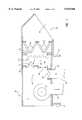
- FIG. 1is an elevation view of a recirculating heating and ventilation system which employs the preferred embodiment of the invention
- FIG. 2is a perspective view of the passive damper which forms part of the system of FIG. 1;
- FIG. 3is a partial view in cross-section taken through the blades of the passive damper in FIG. 2;
- FIG. 4is a graph of an exemplary airflow curve for the passive damper of FIG. 2.
- the preferred embodiment of the inventionis a recirculating heating and ventilation system 10 which is mounted on a roof curb 12 and connected to air ducts 14 and 16 of a building (not shown).
- a centrifugal blower 20connects to the air duct 14 and draws air from an enclosed blower chamber 22 and delivers it to the building through the air duct 14.
- Airis returned from the building through air duct 16 and the volume of this recirculated air is controlled by a recirculation damper 24 mounted in an opening 26 formed in the bottom of the system 10.
- Return air from the buildingmixes with fresh air and is drawn into the chamber 22 by the blower 20.
- the blower 20 and recirculating damper 24are operated in a well known manner by a control system (not shown) to provide the proper amount of air to the building and to recirculate a certain portion of that air.
- the recirculated airis mixed with fresh outside air that is drawn in by the blower 20 through a weatherhood 30.
- a set of air filters 32are mounted in the stream of fresh outside air and an inlet damper 34 is mounted over an air inlet opening 36 to control the amount of fresh air that passes through the air inlet opening 36.
- the inlet damper 34is operated by the same control system that operates the blower 20 and recirculating damper 24.
- the fresh air drawn through the inlet damper 34enters an air inlet chamber 38 located adjacent the mixing chamber 28.
- a dividing wall 40 between these two chambers 28 and 38has two openings through which the fresh air may be drawn into the mixing chamber 28.
- a direct, gas-fired burner 42is mounted in one of these openings, and a passive control damper 44 is mounted in the other opening. The burner 42 heats that portion of the fresh air drawn through the first opening, and the passive control damper 44 shunts the remaining portion of the fresh air around the burner 42.
- the passive control damper 44regulates the air pressure drop across the second opening in the dividing wall 40 as the fresh air passes around the burner 42 on its way to the mixing chamber 28, and in this manner it regulates the pressure drop across the first opening containing the burner 42.
- a constant air pressure drop across the burner 42insures that the proper constant air velocity is maintained at all times for proper combustion. As will now be explained, this is achieved without any active control of the damper 44.
- the passive control damper 44includes a rectangular frame formed by a pair of spaced, vertical sidewalls 50 and 52, a top wall 54 and a bottom wall 56.
- the framedefines a rectangular opening 57 in which two damper blades 58 and 60 are mounted for rotation about two horizontal shafts 62 and 64.
- the shafts 62 and 64extend across the width of the opening 57 and are rotatably fastened to the sidewalls 50 and 52. As shown in FIG. 2, the shafts 62 and 64 extend through the sidewall 50 and a three part linkage couples them together so that they rotate together.
- the linkageincludes arms 66 and 68 which extend radially outward from respective shafts 62 and 64, and a connecting bar 70 which links the ends of these arms together as shown.
- damper blades 58 and 60When the damper blades 58 and 60 are in their closed position as shown in FIG. 3, they substantially fill the rectangular opening 57 and block air flow through it.
- the damper blades 58 and 60are biased in this closed position by weights 74 and 76 which are carried on supporting arms 78 and 80 that attach to the lower damper blade 60.
- the weights 74 and 76provide a bias force that rotates the lower blade 60 closed against a stop 82 mounted along the bottom wall 56.
- a similar stop 84is mounted along the top wall 54 for the upper damper blade 58, and both stops 82 and 84 also serve to seal along one edge of the damper blades 60 and 58 when they are fully closed. Their seals reduce leakage when the damper 44 is closed.
- the damper blades 58 and 60When the air pressure increases on the input side of the passive control damper 44, a force acts on the damper blades 58 and 60 which causes them to rotate open as indicated by the arrows 90 in FIG. 3. The greater the pressure drop across the passive control damper 44 the greater the opening force and the more the damper blades 58 and 60 will open. As will be explained in more detail below, the geometry of the damper 44 determines precisely how it reacts to changes in air pressure to open or close and to thereby change the volume of air flowing through the opening 57.
- the passive control damper 44is designed to regulate the air velocity across the burner 42. It does this by shunting a portion of the fresh air around the burner 42 in response to changes in air pressure.
- the opening profile of the burner 42is set to handle a fixed percentage of the total air flow generated by the blower 20 (e.g. 20% minimum typically) when the air velocity across the burner 42 is at the optimal level for combustion. This establishes an optimal pressure drop across the burner opening in the dividing wall 40. With the recirculating damper 24 fully open, the balance of the air flow (80%) flows through it.
- the pressure drop across the passive control damper 44is equal to that across the burner 42 and the damper weights 74 and 76 are selected to completely close the damper 44 so that it does not shunt any air.
- the systemmay also be set up so that at a minimum outside air setting the passive control damper 44 shunts a small amount of outside air (e.g. 5% to 10%).
- a minimum outside air setting the passive control damper 44shunts a small amount of outside air (e.g. 5% to 10%).
- the recirculation damper 24As the recirculation damper 24 is closed to reduce the volume of recirculated air below 80%, the volume of fresh air must increase above the 20% required by the burner 42 to make up the difference. This increased fresh air flow results in a slight increase in the pressure drop across the burner 42 and the passive control damper 44 "sees" this pressure increase. The increased pressure drop across the second opening opens the damper blades 58 and 60 to shunt the excess fresh air around the burner 42. With the recirculation damper 24 fully closed, the passive control damper 44 is open and is designed to bypass, or shunt, 80% of the total air flow. Thus, without any mechanical linkage or electronic control, the passive control damper 44 responds automatically to changes in the recirculation damper 24 to regulate the air flow through the burner 42 at the optimal level.
- the passive control damper 44also responds to airflow variations caused by other factors. Such variations may be due to internal changes such as dirty filters 32, damper misadjustment, blower speed misadjustment, blower belt slippage, dirty blower wheels, etc. External causes of airflow variations include windage, frost build-up, temperature changes, duct losses, building pressurization, etc. Regardless of the cause, the passive control damper 44 automatically responds to pressure changes across the burner opening to shunt the proper amount of air around the burner 42 and to thereby regulate the airflow therethrough at the optimal amount.
- the geometry of the passive control damper 44determines the manner in which it operates. Referring particularly to FIG. 4, when the air pressure (P s ) is very low across the damper 44, its blades are closed and there is very little airflow (CFM). As the air pressure increases, some leakage airflow occurs before the damper blades 58 and 60 begin to open at the point 100. The leakage airflow (CFM min ) at the point 100 is the lower end of the damper operating range. As the air pressure P s increases further above the point 100, the damper blades 58 and 60 open and begin to shunt airflow. The airflow curve has a small up slope at this segment 102 because the air pressure does increase slightly to open the damper blades further for increased airflow (CFM).
- the mechanical design of the damper 44determines the shape of the airflow curve.
- the operating range of the damper 44is determined by its size (CFM max ) and the air leakage (CFM min ).
- the air pressures (P s ) over which the damper 44 operates, and the precise shape and slope of the segments 102 and 108are determined by a number of physical parameters. Referring particularly to FIGS. 2 and 3, the torque on the blade 60 due to air pressure is a function of the blade length (L) and width (A+B). However, the force produced on that portion (A) of the blade 60 is offset by that portion (B) of the blade 60 located on the other side of the shaft 64.
- the opening torqueis maximum when the blade 60 is perpendicular to the air stream (i.e. fully closed), but the opening torque decreases as its projected area decreases during blade opening.
- the closing bias torque provided by the weights 74 and 76is set to equal the opening torque produced by the blades 58 and 60 when the air pressure (P s ) reaches the point 100 in the airflow curve of FIG. 4. This is substantially the same air pressure (P s ) that should occur across the burner 42 for optimal airflow through it.
- the closing torque provided by weights 74 and 76is the product of their weight and the length (w) of the supporting arms 78 and 80. The amount of weight can be changed to adjust the operating pressure, or the location of the weights on the arms 78 and 80 can be adjusted to change the distance w.
- the effective length (w)is maximum when the blade is closed, but decreases as the blade opens and lifts the weights upward in an arc indicated by arrow 98.
- This closing bias torqueis thus reduced as the blades open to match the reduced opening torque produced by air pressure on the blades 58 and 60. The better the match between the opening and closing torques at all blade angles, the flatter and straighter the segments 102 and 108 in the airflow curve of FIG. 4.
- the segments 102 and 108 in the airflow curve for the passive control damper 44should be straight and flat, and there should be no hysteresis. In other words, throughout the damper operating range the air pressure P s across it and the burner 42 which it shunts should remain constant. In practice this is difficult to achieve and it can lead to an unstable damper that will oscillate under dynamic operating conditions. A certain amount of resistance or damping of blade rotation is, therefore, desirable to maintain stability at the expense of small variations in the regulated air pressure P s .
- the design of the passive control damper 44can be varied in a number of ways.
- the number, size and shape of the damper blades and the opening which they controlcan vary from one application to the next. While rotation of the damper blades about a horizontal axis is shown in the preferred embodiment, the orientation of the blades in the opening and their axis of rotation can vary. Indeed, the blade action need not necessarily be rotary.
- the mechanism for producing the bias force on the damper bladescan also take many forms. For example, one or more springs may be used to produce the bias force and mechanical cams and linkages may be used to tailor the force to match the air pressure force acting on the damper blades throughout their operating range.
- the number, size and arrangement of the passive control damper in the heating systemcan also be varied.
- two or more passive control dampersmay be disposed around the burner 42 in order to even out the air flow through the burner. It is also possible to shunt air around the burner by locating the passive control damper in other walls of the heating system.
- the passive control damper 44can be located in the recirculation air duct 16 and an active control damper may be mounted in the divider wall 40 to shunt air around the burner 42. In this arrangement the active control damper is operated by the building control system to adjust the level of outside air.
- the passive control damper 44in this embodiment adjusts the amount of recirculated air to maintain the desired static pressure drop across the burner 42.
- a portion of the air drawn by the blower 20 into the blower chamber 22is recirculated by the damper 44 and is thereby indirectly shunted around the burner 42.
- This arrangementdoes not provide the same degree of regulation as the direct shunt of the preferred embodiment, and a second, much smaller, passive control damper 44 may also be mounted in the divider wall 40 along with the active control damper to adjust for changes in the fresh intake air pressure that are not "seen" by the passive control damper 44 mounted in the recirculating air duct 16.
- the present inventionis also particularly well suited for use in a variable volume system in which air is not recirculated through the blower.
- a variable volume systemin which air is not recirculated through the blower.
- the passive control damper 44operates to maintain static conditions across the burner 42 as the total air drawn in from outside is changed.
Landscapes
- Engineering & Computer Science (AREA)
- Physics & Mathematics (AREA)
- Thermal Sciences (AREA)
- Chemical & Material Sciences (AREA)
- Combustion & Propulsion (AREA)
- Mechanical Engineering (AREA)
- General Engineering & Computer Science (AREA)
- Regulation And Control Of Combustion (AREA)
- Air Supply (AREA)
Abstract
Description
Claims (11)
Priority Applications (2)
| Application Number | Priority Date | Filing Date | Title |
|---|---|---|---|
| US08/949,261US5915960A (en) | 1997-10-13 | 1997-10-13 | Direct gas-fired heating and ventilation system with passive control damper |
| CA002242652ACA2242652C (en) | 1997-10-13 | 1998-07-02 | Direct gas-fired heating and ventilation system with passive control damper |
Applications Claiming Priority (1)
| Application Number | Priority Date | Filing Date | Title |
|---|---|---|---|
| US08/949,261US5915960A (en) | 1997-10-13 | 1997-10-13 | Direct gas-fired heating and ventilation system with passive control damper |
Publications (1)
| Publication Number | Publication Date |
|---|---|
| US5915960Atrue US5915960A (en) | 1999-06-29 |
Family
ID=25488818
Family Applications (1)
| Application Number | Title | Priority Date | Filing Date |
|---|---|---|---|
| US08/949,261Expired - LifetimeUS5915960A (en) | 1997-10-13 | 1997-10-13 | Direct gas-fired heating and ventilation system with passive control damper |
Country Status (2)
| Country | Link |
|---|---|
| US (1) | US5915960A (en) |
| CA (1) | CA2242652C (en) |
Cited By (36)
| Publication number | Priority date | Publication date | Assignee | Title |
|---|---|---|---|---|
| FR2807500A1 (en)* | 2000-04-11 | 2001-10-12 | 4E | CONTROLLED TEMPERATURE AIR GENERATOR, PARTICULARLY FOR LIVESTOCK OR INDUSTRIAL BUILDINGS |
| US6431457B1 (en)* | 1999-09-28 | 2002-08-13 | Rapid Engineering, Inc. | Air heater control |
| US20030123863A1 (en)* | 2000-12-07 | 2003-07-03 | Aos Holding Company | Rooftop water heater |
| US6591788B2 (en) | 2000-12-07 | 2003-07-15 | Aos Holding Company | Rooftop water heater |
| US6629523B2 (en)* | 2001-01-11 | 2003-10-07 | Captive-Aire Systems, Inc. | Heated make-up air system |
| US20050051155A1 (en)* | 2003-08-12 | 2005-03-10 | Tomlinson John L. | Direct-fired, gas-fueled heater |
| US20060107897A1 (en)* | 2004-11-24 | 2006-05-25 | San Ford Machinery Co., Ltd. | Dry spray device |
| US20060266348A1 (en)* | 2005-03-11 | 2006-11-30 | Absolutaire, Inc. | Direct fired heater with improved set-up features |
| US20090093210A1 (en)* | 2007-10-09 | 2009-04-09 | Oy Halton Group Ltd. | Damper suitable for liquid aerosol-laden flow streams |
| US7634977B2 (en) | 2006-08-16 | 2009-12-22 | Aos Holding Company | Gas water heater |
| US20100112927A1 (en)* | 2008-11-05 | 2010-05-06 | Gm Global Technology Operations, Inc. | Adjustable profile plate assembly for use with an air make-up system |
| US20100116225A1 (en)* | 2008-10-16 | 2010-05-13 | Lochinvar Corporation | Integrated Dual Chamber Burner |
| US20100294257A1 (en)* | 2009-05-15 | 2010-11-25 | Robert Thayer | Direct-fired heating system |
| US20110146594A1 (en)* | 2009-12-22 | 2011-06-23 | Lochinvar Corporation | Fire Tube Heater |
| US20120149294A1 (en)* | 2010-12-13 | 2012-06-14 | Robert Labrecque | Extraction Fan Assembly Including a Damper that Closes Firmly when the Fan is Not Running and Reduces the Pressure Drop when the Fan is Running at Full Speed |
| US20120255219A1 (en)* | 2011-04-06 | 2012-10-11 | Technologies Holdings Corp. | Self-Contained Heating Unit for Thermal Pest Control |
| US8720109B2 (en) | 2011-01-25 | 2014-05-13 | Technologies Holdings Corp. | Portable heating system for pest control |
| US20140170961A1 (en)* | 2010-12-13 | 2014-06-19 | Robert Labrecque | Method for Controlling Air Flow of an Extraction Fan |
| US8756857B2 (en) | 2011-01-14 | 2014-06-24 | Technologies Holdings Corp. | Hydronic heating system and method for pest control |
| US8807092B2 (en) | 2008-10-16 | 2014-08-19 | Lochinvar, Llc | Gas fired modulating water heating appliance with dual combustion air premix blowers |
| US20140373826A1 (en)* | 2013-06-19 | 2014-12-25 | Anthony Cote | Passive Constant Pressure Hatch for Fresh Air Direct Fired Gas Heated Ventilation Systems |
| US9097436B1 (en) | 2010-12-27 | 2015-08-04 | Lochinvar, Llc | Integrated dual chamber burner with remote communicating flame strip |
| US20150354867A1 (en)* | 2014-06-06 | 2015-12-10 | Enthaltec, Inc. | Hvac roof curb retrofit |
| US9464805B2 (en) | 2013-01-16 | 2016-10-11 | Lochinvar, Llc | Modulating burner |
| US9863649B2 (en) | 2013-03-15 | 2018-01-09 | Mitek Holdings, Inc. | Dual bypass direct fired heating system with pressure control |
| US10054130B1 (en) | 2017-06-19 | 2018-08-21 | Dekalb Blower Inc. | Rotary seal for an industrial fan assembly |
| US10356943B2 (en) | 2017-06-19 | 2019-07-16 | Dekalb Blower Inc. | Industrial fan assembly |
| US10605258B2 (en) | 2017-06-19 | 2020-03-31 | Dekalb Blower Inc. | Forward curved blade impeller for an industrial fan assembly |
| US10605262B2 (en) | 2017-06-19 | 2020-03-31 | Dekalb Blower Inc. | Axial blade impeller for an industrial fan assembly |
| US10619886B2 (en) | 2015-10-01 | 2020-04-14 | Acme Engineering And Manufacturing Corp. | Airfoil damper |
| US10935040B2 (en) | 2017-06-19 | 2021-03-02 | The Boeing Company | Radial blade impeller for an industrial fan assembly |
| US11234345B2 (en)* | 2019-11-15 | 2022-01-25 | Dell Products, L.P. | Data center having a differential pressure relief mechanism between cold and hot aisles |
| US11320189B1 (en)* | 2020-11-11 | 2022-05-03 | Tippmann Construction, Llc | Quick freeze pallet racks with variable louvered doors |
| US11374458B2 (en) | 2018-10-24 | 2022-06-28 | Dekalb Blower Inc. | Electric motor with fluid cooling |
| US11988434B2 (en) | 2021-05-03 | 2024-05-21 | Tippmann Engineering, Llc | Heat transfer system for warehoused goods |
| USRE50003E1 (en) | 2015-09-30 | 2024-06-11 | Tippmann Engineering, Llc | Heat transfer system for warehoused goods |
Families Citing this family (2)
| Publication number | Priority date | Publication date | Assignee | Title |
|---|---|---|---|---|
| AU2014200657B2 (en)* | 2003-05-29 | 2015-03-12 | Sustainable Agricultural Machinery Developments Pty Ltd | Ventilation System |
| AU2014101263A4 (en)* | 2003-05-29 | 2014-11-13 | Sustainable Agricultural Machinery Developments Pty Ltd | Ventilation System |
Citations (13)
| Publication number | Priority date | Publication date | Assignee | Title |
|---|---|---|---|---|
| US3417977A (en)* | 1967-02-09 | 1968-12-24 | Mammoth Ind Inc | Air control system for heating unit |
| US3591150A (en)* | 1969-01-15 | 1971-07-06 | Weather Rite Inc | Furnace |
| US3765398A (en)* | 1972-10-19 | 1973-10-16 | Carrier Corp | Heating apparatus for outdoors operation |
| US4278423A (en)* | 1979-11-27 | 1981-07-14 | Siccardi Frank J | Heating and ventilating system for poultry houses |
| US4289447A (en)* | 1979-10-12 | 1981-09-15 | General Electric Company | Metal-ceramic turbine shroud and method of making the same |
| US4325352A (en)* | 1980-09-26 | 1982-04-20 | Rapid Engineering Inc. | Internal recirculation device |
| US4429679A (en)* | 1981-09-30 | 1984-02-07 | Rapid Engineering, Inc. | Modulair air heater |
| US4573912A (en)* | 1984-06-26 | 1986-03-04 | Itt Corporation | Space heater |
| US4674475A (en)* | 1985-10-31 | 1987-06-23 | Fl Industries, Inc. | Gas fired furnace |
| US4887641A (en)* | 1988-12-12 | 1989-12-19 | Mestek, Inc. | Modified parallel blade damper for an air handling system |
| US4917074A (en)* | 1989-04-03 | 1990-04-17 | Saturn Corporation | Direct gas-fired heating and ventilation method and apparatus |
| US5257958A (en)* | 1993-02-11 | 1993-11-02 | Rapid Engineering, Inc. | Pressure override control for air treatment unit |
| US5597354A (en)* | 1995-06-13 | 1997-01-28 | Johnson Service Company | Indoor air quality control for constant volume heating, ventilating and air conditioning units |
- 1997
- 1997-10-13USUS08/949,261patent/US5915960A/ennot_activeExpired - Lifetime
- 1998
- 1998-07-02CACA002242652Apatent/CA2242652C/ennot_activeExpired - Lifetime
Patent Citations (13)
| Publication number | Priority date | Publication date | Assignee | Title |
|---|---|---|---|---|
| US3417977A (en)* | 1967-02-09 | 1968-12-24 | Mammoth Ind Inc | Air control system for heating unit |
| US3591150A (en)* | 1969-01-15 | 1971-07-06 | Weather Rite Inc | Furnace |
| US3765398A (en)* | 1972-10-19 | 1973-10-16 | Carrier Corp | Heating apparatus for outdoors operation |
| US4289447A (en)* | 1979-10-12 | 1981-09-15 | General Electric Company | Metal-ceramic turbine shroud and method of making the same |
| US4278423A (en)* | 1979-11-27 | 1981-07-14 | Siccardi Frank J | Heating and ventilating system for poultry houses |
| US4325352A (en)* | 1980-09-26 | 1982-04-20 | Rapid Engineering Inc. | Internal recirculation device |
| US4429679A (en)* | 1981-09-30 | 1984-02-07 | Rapid Engineering, Inc. | Modulair air heater |
| US4573912A (en)* | 1984-06-26 | 1986-03-04 | Itt Corporation | Space heater |
| US4674475A (en)* | 1985-10-31 | 1987-06-23 | Fl Industries, Inc. | Gas fired furnace |
| US4887641A (en)* | 1988-12-12 | 1989-12-19 | Mestek, Inc. | Modified parallel blade damper for an air handling system |
| US4917074A (en)* | 1989-04-03 | 1990-04-17 | Saturn Corporation | Direct gas-fired heating and ventilation method and apparatus |
| US5257958A (en)* | 1993-02-11 | 1993-11-02 | Rapid Engineering, Inc. | Pressure override control for air treatment unit |
| US5597354A (en)* | 1995-06-13 | 1997-01-28 | Johnson Service Company | Indoor air quality control for constant volume heating, ventilating and air conditioning units |
Cited By (61)
| Publication number | Priority date | Publication date | Assignee | Title |
|---|---|---|---|---|
| US6431457B1 (en)* | 1999-09-28 | 2002-08-13 | Rapid Engineering, Inc. | Air heater control |
| FR2807500A1 (en)* | 2000-04-11 | 2001-10-12 | 4E | CONTROLLED TEMPERATURE AIR GENERATOR, PARTICULARLY FOR LIVESTOCK OR INDUSTRIAL BUILDINGS |
| EP1146292A1 (en)* | 2000-04-11 | 2001-10-17 | Zi Nantes Carquefou | Air generating device having controlled temperature in particular for livestock breeding |
| US6679014B2 (en) | 2000-12-07 | 2004-01-20 | Aos Holding Company | Rooftop water heater |
| US6591788B2 (en) | 2000-12-07 | 2003-07-15 | Aos Holding Company | Rooftop water heater |
| US7277627B2 (en) | 2000-12-07 | 2007-10-02 | Aos Holding Company | Rooftop water heater |
| US20030123863A1 (en)* | 2000-12-07 | 2003-07-03 | Aos Holding Company | Rooftop water heater |
| US6629523B2 (en)* | 2001-01-11 | 2003-10-07 | Captive-Aire Systems, Inc. | Heated make-up air system |
| US20050051155A1 (en)* | 2003-08-12 | 2005-03-10 | Tomlinson John L. | Direct-fired, gas-fueled heater |
| US20060107897A1 (en)* | 2004-11-24 | 2006-05-25 | San Ford Machinery Co., Ltd. | Dry spray device |
| US7455580B2 (en)* | 2004-11-24 | 2008-11-25 | San Ford Machinery Co., Ltd. | Dry spray device |
| US20060266348A1 (en)* | 2005-03-11 | 2006-11-30 | Absolutaire, Inc. | Direct fired heater with improved set-up features |
| US7634977B2 (en) | 2006-08-16 | 2009-12-22 | Aos Holding Company | Gas water heater |
| US9702565B2 (en)* | 2007-10-09 | 2017-07-11 | Oy Halto Group Ltd. | Damper suitable for liquid aerosol-laden flow streams |
| US10480797B2 (en) | 2007-10-09 | 2019-11-19 | Oy Halton Group Ltd. | Damper suitable for liquid aerosol-laden flow streams |
| US9719686B2 (en) | 2007-10-09 | 2017-08-01 | Oy Halton Group Ltd. | Damper suitable for liquid aerosol-laden flow streams |
| US20090093210A1 (en)* | 2007-10-09 | 2009-04-09 | Oy Halton Group Ltd. | Damper suitable for liquid aerosol-laden flow streams |
| US8807092B2 (en) | 2008-10-16 | 2014-08-19 | Lochinvar, Llc | Gas fired modulating water heating appliance with dual combustion air premix blowers |
| US20100116225A1 (en)* | 2008-10-16 | 2010-05-13 | Lochinvar Corporation | Integrated Dual Chamber Burner |
| US8517720B2 (en) | 2008-10-16 | 2013-08-27 | Lochinvar, Llc | Integrated dual chamber burner |
| US20100112927A1 (en)* | 2008-11-05 | 2010-05-06 | Gm Global Technology Operations, Inc. | Adjustable profile plate assembly for use with an air make-up system |
| US9174254B2 (en)* | 2008-11-05 | 2015-11-03 | GM Global Technology Operations LLC | Adjustable profile plate assembly for use with an air make-up system |
| US20100294257A1 (en)* | 2009-05-15 | 2010-11-25 | Robert Thayer | Direct-fired heating system |
| US20110146594A1 (en)* | 2009-12-22 | 2011-06-23 | Lochinvar Corporation | Fire Tube Heater |
| US8844472B2 (en) | 2009-12-22 | 2014-09-30 | Lochinvar, Llc | Fire tube heater |
| US20120149294A1 (en)* | 2010-12-13 | 2012-06-14 | Robert Labrecque | Extraction Fan Assembly Including a Damper that Closes Firmly when the Fan is Not Running and Reduces the Pressure Drop when the Fan is Running at Full Speed |
| US9383117B2 (en)* | 2010-12-13 | 2016-07-05 | Groupe Ro-Main Inc. | Method for controlling air flow of an extraction fan |
| US20140170961A1 (en)* | 2010-12-13 | 2014-06-19 | Robert Labrecque | Method for Controlling Air Flow of an Extraction Fan |
| US9587845B2 (en) | 2010-12-13 | 2017-03-07 | Groupe Ro-Main Inc. | Extraction fan assembly including a damper that closes firmly when the fan is not running and reduces the pressure drop when the fan is running at full speed |
| US8672734B2 (en)* | 2010-12-13 | 2014-03-18 | Robert Labrecque | Extraction fan assembly including a damper that closes firmly when the fan is not running and reduces the pressure drop when the fan is running at full speed |
| US9097436B1 (en) | 2010-12-27 | 2015-08-04 | Lochinvar, Llc | Integrated dual chamber burner with remote communicating flame strip |
| US8756857B2 (en) | 2011-01-14 | 2014-06-24 | Technologies Holdings Corp. | Hydronic heating system and method for pest control |
| US9578867B2 (en) | 2011-01-25 | 2017-02-28 | Technologies Holding Corp. | Portable heating system and method for pest control |
| US10051853B2 (en) | 2011-01-25 | 2018-08-21 | Therma-Stor LLC | Portable heating system and method for pest control |
| US9992990B2 (en) | 2011-01-25 | 2018-06-12 | Therma-Stor LLC | Portable heating system and method for pest control |
| US9374991B2 (en) | 2011-01-25 | 2016-06-28 | Technologies Holdings Corp. | Portable heating system and method for pest control |
| US8720109B2 (en) | 2011-01-25 | 2014-05-13 | Technologies Holdings Corp. | Portable heating system for pest control |
| US9930878B2 (en) | 2011-01-25 | 2018-04-03 | Therma-Stor LLC | Portable heating system and method for pest control |
| US9237742B2 (en) | 2011-01-25 | 2016-01-19 | Technologies Holdings Corp. | Portable heating system and method for pest control |
| US9807994B2 (en) | 2011-01-25 | 2017-11-07 | Technologies Holdings Corp. | Portable heating system and method for pest control |
| US20120255219A1 (en)* | 2011-04-06 | 2012-10-11 | Technologies Holdings Corp. | Self-Contained Heating Unit for Thermal Pest Control |
| US8479439B2 (en)* | 2011-04-06 | 2013-07-09 | Technologies Holding Corp. | Self-contained heating unit for thermal pest control |
| US8479440B2 (en)* | 2011-04-06 | 2013-07-09 | Technologies Holdings Corp. | Self-contained heating unit for thermal pest control |
| EP2508069B1 (en)* | 2011-04-06 | 2016-03-23 | Technologies Holdings Corp. | Self-contained heating unit for thermal pest control |
| US10208953B2 (en) | 2013-01-16 | 2019-02-19 | A. O. Smith Corporation | Modulating burner |
| US9464805B2 (en) | 2013-01-16 | 2016-10-11 | Lochinvar, Llc | Modulating burner |
| US9863649B2 (en) | 2013-03-15 | 2018-01-09 | Mitek Holdings, Inc. | Dual bypass direct fired heating system with pressure control |
| US9562698B2 (en)* | 2013-06-19 | 2017-02-07 | Anthony Cote | Passive constant pressure hatch for fresh air direct fired gas heated ventilation systems |
| US20140373826A1 (en)* | 2013-06-19 | 2014-12-25 | Anthony Cote | Passive Constant Pressure Hatch for Fresh Air Direct Fired Gas Heated Ventilation Systems |
| US20150354867A1 (en)* | 2014-06-06 | 2015-12-10 | Enthaltec, Inc. | Hvac roof curb retrofit |
| USRE50003E1 (en) | 2015-09-30 | 2024-06-11 | Tippmann Engineering, Llc | Heat transfer system for warehoused goods |
| US10619886B2 (en) | 2015-10-01 | 2020-04-14 | Acme Engineering And Manufacturing Corp. | Airfoil damper |
| US10605258B2 (en) | 2017-06-19 | 2020-03-31 | Dekalb Blower Inc. | Forward curved blade impeller for an industrial fan assembly |
| US10605262B2 (en) | 2017-06-19 | 2020-03-31 | Dekalb Blower Inc. | Axial blade impeller for an industrial fan assembly |
| US10054130B1 (en) | 2017-06-19 | 2018-08-21 | Dekalb Blower Inc. | Rotary seal for an industrial fan assembly |
| US10935040B2 (en) | 2017-06-19 | 2021-03-02 | The Boeing Company | Radial blade impeller for an industrial fan assembly |
| US10356943B2 (en) | 2017-06-19 | 2019-07-16 | Dekalb Blower Inc. | Industrial fan assembly |
| US11374458B2 (en) | 2018-10-24 | 2022-06-28 | Dekalb Blower Inc. | Electric motor with fluid cooling |
| US11234345B2 (en)* | 2019-11-15 | 2022-01-25 | Dell Products, L.P. | Data center having a differential pressure relief mechanism between cold and hot aisles |
| US11320189B1 (en)* | 2020-11-11 | 2022-05-03 | Tippmann Construction, Llc | Quick freeze pallet racks with variable louvered doors |
| US11988434B2 (en) | 2021-05-03 | 2024-05-21 | Tippmann Engineering, Llc | Heat transfer system for warehoused goods |
Also Published As
| Publication number | Publication date |
|---|---|
| CA2242652C (en) | 2002-07-30 |
| CA2242652A1 (en) | 1999-04-13 |
Similar Documents
| Publication | Publication Date | Title |
|---|---|---|
| US5915960A (en) | Direct gas-fired heating and ventilation system with passive control damper | |
| US5249596A (en) | Residential heating and air conditioning barometric bypass damper | |
| US6126540A (en) | Staged power exhaust for HVAC air handling units | |
| US6604688B2 (en) | Air handler with return air bypass for improved dehumidification | |
| CA2223751C (en) | Method and means for improved ceiling ventilation | |
| US5993195A (en) | Combustion air regulating apparatus for use with induced draft furnaces | |
| US4429679A (en) | Modulair air heater | |
| RU2543594C2 (en) | Air supply unit | |
| CA1285171C (en) | Vortex valve flow controller in vav systems | |
| CA2206320C (en) | Environmental control airhouse with variable output | |
| US6629523B2 (en) | Heated make-up air system | |
| CA1241589A (en) | Space heater | |
| US9562698B2 (en) | Passive constant pressure hatch for fresh air direct fired gas heated ventilation systems | |
| US5236393A (en) | Bypass damper in series-type ventilation fan | |
| FI77216C (en) | Control device for the blow pressure in a glass hardening device's cooling nozzles. | |
| US3625629A (en) | Proportional blower | |
| MXPA98006533A (en) | System for ventilation and heating activated with direct gas, with regulator of control shot pas | |
| WO2010010230A2 (en) | Air conditioning system and method of air conditioning | |
| JP3256228B2 (en) | Flow controller | |
| CN109838808B (en) | Heat load adjusting device and full-premix gas water heater | |
| CA2818376C (en) | Passive constant pressure hatch for fresh air direct fired gas heated ventilation systems | |
| JPH03207944A (en) | Air-conditioner | |
| JPH0345051Y2 (en) | ||
| US20040046038A1 (en) | Blending air apparatus | |
| JPH02309150A (en) | Air conditioner |
Legal Events
| Date | Code | Title | Description |
|---|---|---|---|
| AS | Assignment | Owner name:GREENHECK FAN CORPORATION, WISCONSIN Free format text:ASSIGNMENT OF ASSIGNORS INTEREST;ASSIGNORS:CHECK, CHRIS B.;SCHMIDT, JAY J.;KNIERIEM, BRUCE L.;REEL/FRAME:008962/0437 Effective date:19971003 | |
| STCF | Information on status: patent grant | Free format text:PATENTED CASE | |
| FPAY | Fee payment | Year of fee payment:4 | |
| FPAY | Fee payment | Year of fee payment:8 | |
| AS | Assignment | Owner name:BANK OF AMERICA, N.A., AS COLLATERAL AGENT, ILLINO Free format text:NOTICE OF GRANT OF SECURITY INTEREST;ASSIGNOR:GREENHECK FAN CORPORATION;REEL/FRAME:019930/0208 Effective date:20070928 Owner name:BANK OF AMERICA, N.A., AS COLLATERAL AGENT,ILLINOI Free format text:NOTICE OF GRANT OF SECURITY INTEREST;ASSIGNOR:GREENHECK FAN CORPORATION;REEL/FRAME:019930/0208 Effective date:20070928 | |
| FPAY | Fee payment | Year of fee payment:12 | |
| AS | Assignment | Owner name:BANK OF AMERICA, N.A., AS COLLATERAL AGENT, ILLINO Free format text:NOTICE OF GRANT OF SECURITY INTEREST IN PATENTS;ASSIGNOR:GREENHECK FAN CORPORATION;REEL/FRAME:026936/0152 Effective date:20110916 | |
| AS | Assignment | Owner name:GREENHECK FAN CORPORATION, WISCONSIN Free format text:TERMINATION OF SECURITY INTEREST IN PATENTS;ASSIGNOR:BANK OF AMERICA, N.A., AS COLLATERAL AGENT;REEL/FRAME:026957/0708 Effective date:20110916 | |
| AS | Assignment | Owner name:BMO HARRIS BANK N.A., ILLINOIS Free format text:SECURITY INTEREST;ASSIGNOR:BANK OF AMERICA, N.A.;REEL/FRAME:058310/0390 Effective date:20211202 |