US5915640A - Reel for storing surplus cable - Google Patents
Reel for storing surplus cableDownload PDFInfo
- Publication number
- US5915640A US5915640AUS09/133,180US13318098AUS5915640AUS 5915640 AUS5915640 AUS 5915640AUS 13318098 AUS13318098 AUS 13318098AUS 5915640 AUS5915640 AUS 5915640A
- Authority
- US
- United States
- Prior art keywords
- housing part
- housing
- reel
- housing parts
- another
- Prior art date
- Legal status (The legal status is an assumption and is not a legal conclusion. Google has not performed a legal analysis and makes no representation as to the accuracy of the status listed.)
- Expired - Lifetime
Links
Images
Classifications
- H—ELECTRICITY
- H02—GENERATION; CONVERSION OR DISTRIBUTION OF ELECTRIC POWER
- H02G—INSTALLATION OF ELECTRIC CABLES OR LINES, OR OF COMBINED OPTICAL AND ELECTRIC CABLES OR LINES
- H02G11/00—Arrangements of electric cables or lines between relatively-movable parts
- H02G11/02—Arrangements of electric cables or lines between relatively-movable parts using take-up reel or drum
- B—PERFORMING OPERATIONS; TRANSPORTING
- B65—CONVEYING; PACKING; STORING; HANDLING THIN OR FILAMENTARY MATERIAL
- B65H—HANDLING THIN OR FILAMENTARY MATERIAL, e.g. SHEETS, WEBS, CABLES
- B65H75/00—Storing webs, tapes, or filamentary material, e.g. on reels
- B65H75/02—Cores, formers, supports, or holders for coiled, wound, or folded material, e.g. reels, spindles, bobbins, cop tubes, cans, mandrels or chucks
- B65H75/04—Kinds or types
- B65H75/08—Kinds or types of circular or polygonal cross-section
- B65H75/14—Kinds or types of circular or polygonal cross-section with two end flanges
- B65H75/143—Kinds or types of circular or polygonal cross-section with two end flanges at least one end flange being shaped to cover the windings
- B—PERFORMING OPERATIONS; TRANSPORTING
- B65—CONVEYING; PACKING; STORING; HANDLING THIN OR FILAMENTARY MATERIAL
- B65H—HANDLING THIN OR FILAMENTARY MATERIAL, e.g. SHEETS, WEBS, CABLES
- B65H75/00—Storing webs, tapes, or filamentary material, e.g. on reels
- B65H75/02—Cores, formers, supports, or holders for coiled, wound, or folded material, e.g. reels, spindles, bobbins, cop tubes, cans, mandrels or chucks
- B65H75/34—Cores, formers, supports, or holders for coiled, wound, or folded material, e.g. reels, spindles, bobbins, cop tubes, cans, mandrels or chucks specially adapted or mounted for storing and repeatedly paying-out and re-storing lengths of material provided for particular purposes, e.g. anchored hoses, power cables
- B65H75/38—Cores, formers, supports, or holders for coiled, wound, or folded material, e.g. reels, spindles, bobbins, cop tubes, cans, mandrels or chucks specially adapted or mounted for storing and repeatedly paying-out and re-storing lengths of material provided for particular purposes, e.g. anchored hoses, power cables involving the use of a core or former internal to, and supporting, a stored package of material
- B65H75/40—Cores, formers, supports, or holders for coiled, wound, or folded material, e.g. reels, spindles, bobbins, cop tubes, cans, mandrels or chucks specially adapted or mounted for storing and repeatedly paying-out and re-storing lengths of material provided for particular purposes, e.g. anchored hoses, power cables involving the use of a core or former internal to, and supporting, a stored package of material mobile or transportable
- B65H75/406—Cores, formers, supports, or holders for coiled, wound, or folded material, e.g. reels, spindles, bobbins, cop tubes, cans, mandrels or chucks specially adapted or mounted for storing and repeatedly paying-out and re-storing lengths of material provided for particular purposes, e.g. anchored hoses, power cables involving the use of a core or former internal to, and supporting, a stored package of material mobile or transportable hand-held during use
Definitions
- the inventionrelates to a reel for winding up and unwinding a free part of a wire.
- a reel of this kindis known from U.S. Pat. No. 4,390,142.
- a housingenclosing a hollow chamber is provided with a disc which can rotate therein and has a slot for receiving and entraining a wire.
- the housingOn its periphery, the housing is provided with a slot through which a wire loop can be pushed, which wire loop should then be placed in the slot in the rotatable disc.
- a drawback hereis that a reel of this kind comprises many complex components, is difficult to assemble and dismantle and is relatively expensive to produce. If a wound-up wire part, for example a thick, stiff computer lead, becomes stuck in a reel of this kind, such that the rotatable disc can no longer be rotated with respect to the housing, this wire part can only be released by dismantling the reel. In this case, this dismantling is extremely laborious and time-consuming.
- the object of the present inventionis to provide a reel in which these drawbacks are eliminated.
- a reelcomprising a first housing part and a second housing part, which are connected so as to be able to rotate with respect to one another about a common axis and together enclose a chamber for receiving the wire, a central member being present in the chamber, each housing part having a free rim which extends in a plane perpendicular to the axis common, and each housing part comprising a slot which extends as far as the free rim.
- the housing partsare connected to one another by means of a connection which is releasable via an operating member. In this way, it is possible to release the housing parts from one another in a simple manner, as a result of which the already wound-up wire part can be slid off the central member. This is advantageous both in the case of the example mentioned of a wire part that became stucked and is also the quickest way of unwinding again a long portion of wound-up wire.
- the reel according to the inventionno longer requires a separately rotatable disc which, moreover, has to be accommodated inside the housing and has to be operable from the outside. As a result, the reel according to the invention can be produced very simply and inexpensively.
- the first housing partis provided at the location of the axis with a socket including an inwardly projecting stop rim
- the second housing partis provided with one or more resilient lips with snap-in rims which engage behind the stop rim in the first housing part so as to form the connection between the housing parts
- the operating memberbeing an element which is displaceable in the socket of the first housing part and can interact with the resilient lips in order, if desired, to release the engagement of the said lips with the stop rim in the first housing part.
- the inventionrelates to a method of packaging a reel of this kind, the first and second housing parts being clamped around an information card, the central member extending through a cutout made in the information card.
- the packagingin this case merely comprises an information card which is simple and inexpensive to produce. Due to the fact that the reel can be assembled rapidly and simply, the reel can likewise be clamped rapidly and simply around the information card, thus providing a very inexpensive and effective packaging, which is possible due to the special design of the reel according to the invention.
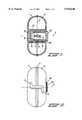
- FIG. 1is a cross-sectional view of a preferred embodiment of a reel according to the invention
- FIG. 2is a front view of the reel in FIG. 1;
- FIGS. 3 and 4show the winding-up operation of the reel of FIG. 1 in two steps
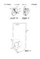
- FIG. 5shows an information card with, in broken lines, a reel clamped around it.
- the reel shown in FIGS. 1 and 2has a housing comprising a first housing part and a second housing part 1, 2 which can rotate with respect to one another about an axis 3.
- the housingmay have any desired form, for example the form of a box or a sphere.
- the housing parts 1, 2each have a free rim 4 which projects in a plane perpendicular to the axis 3.
- the housing parts 1, 2are each provided in the center with a socket 6, 8, with an inwardly projecting stop rim 7, 9 in each socket 6, 8.
- the free rims 4 of the housing parts 1, 2substantially adjoin one another and thus enclose a chamber with the two sockets 6, 8 in the center.
- a hollow cylinder 10is arranged around the sockets 6, 8.
- this hollow cylinder 10can rotate freely with respect to the housing parts 1, 2 and the sockets 6, 8 which are connected thereto.
- Each housing part 1, 2is provided with a slot 5 which extends as far as the free rim 4.
- the connection between the housing parts 1, 2is in this case formed by a connection element 20 accommodated in the socket 8.
- the connection element 20is in this case of bush-like design and at its end comprises four resilient lips 21. These resilient lips 21 are formed in a simple manner by arranging slots in the all of the bush-shaped connection element 20, which slots extend in the longitudinal direction as far as the end. Instead of four, it is also possible to use any other number of desired lips.
- the resilient lips 21have snap-in rims which engage behind the stop rim 7.
- connection element 20moreover bears with a rim against the stop rim 9
- this connectioncan be released in a simple manner via an operating member 25.
- the operating member 25is formed by a cap-shaped element which is accommodated displaceably in the socket 6.
- the operating member 25is provided with a recess with a bevelled edge. This bevelled edge can engage on the resilient lips 21, which are advantageously likewise provided with a bevel at the location of the snap-in rims.
- the resilient lips 21are pressed inwards in the radial direction due to an interaction between the sloping edges. In this way, the snap-in rims of the resilient lips 21 are disengaged from the stop rim 7.
- the housing parts 1, 2can then be removed from one another.
- the housing parts 41, 42should be rotated with respect to one another such that the slots 44, 45 are aligned with one another.
- Part of a wire which is to be wound upfor example a lead of a telephone, computer or lamp, can then be placed in the slots 44, 45.
- the housing parts 41, 42By then rotating the housing parts 41, 42 in opposite directions with respect to one another, as indicated by the arrows 46, the wire is wound up around a central member situated in the housing.
- the housing parts 41, 42should be rotated with respect to one another just until the wire has been shortened to the desired length.
- the wirecan be unwound again by rotating the housing parts 41, 42 in the opposite direction with respect to one another or by breaking the connection between the housing parts, as a result of which the housing parts 41, 42 can be removed from one another and the wound-up wire part can easily be slid off the central member.
- the slots 5comprise a part which is at an angle of 90° to the initial direction of the slots 5.
- the wireis held better in the separate slots 5 while winding up.
- the slotmay also have any other desired form.
- the central member in the reel shown in FIG. 1is formed by the freely rotatable hollow cylinder 10.
- the entire reelcan easily be slid over the wire after part of the wire has already been wound up.
- the hollow cylinder 10will rotate with respect to the housing parts 1, 2, as a result of which a piece of wire is released on one side of the wound-up wire part, while an equally large piece of wire is wound up on the other end. Due to this possibility of sliding, it is no longer necessary to place the reel precisely at the center of the wire part which is to be wound up, and following the winding operation the reel can be visually concealed in a simple manner, for example by sliding it behind a cupboard.
- the hollow cylinder 10strengthens the connection of the housing parts 1, 2.
- the hollow cylinder 10can also be omitted, in which case the wire is wound directly around the sockets 6, 8. It is also possible to make the sockets 6, 8 much smaller, as a result of which they no longer bear against one another in the center. In that case, however, it is essential that a cylindrical part be used which can be slid over the sockets.
- the resilient lipsform part of one of the sockets.
- the reelmay comprise only three components, namely two housing parts and an operating member.
- the embodiment shown with the separate connection element 20has the advantage that the housing parts 1, 2 can be identical to one another. This is particularly advantageous for manufacturing the separate components of the reel.
- Another possibility for an easily releasable connection between the housing partsmay be formed by using a so-called bayonet closure (not shown).
- the bayonet closuremay then, for example, be implemented between a connection element which is connected to the second housing part and the operating member which is connected to the first housing part, or between a connection element which is connected to the second housing part and the first housing part.
- the connection elementshould be able to rotate freely in the second housing part and thus also forms the operating member.
- An inwardly projecting snap-in rim 31is arranged in the socket 6.
- the operating member 25can no longer fall out of the housing part 1. Due to the fact that the operating member 25 is accommodated countersunk in the socket 6, and part of the connection element 20 projects outside the housing part 2, this projecting part of the connection element 20 can be accommodated in a clamping manner in the socket of a second reel of this design.
- a snap-in rim 30is arranged on the projecting part of the connection element 20, which rim comes to rest behind the snap-in rim 31 after coupling two reels.
- FIG. 5shows an information card 50, in which a keyhole-shaped cutout 51 is situated.
- the cylindrical part 53 of the lock-shaped cutout 51is intended to receive the central member of a reel 52 according to the invention, which is indicated only by dashed lines.
- the slot-shaped part 54 of the lock-shaped cutout 51extends in particular in the direction of an edge of the information card 50 as far as beyond the free rim of the housing parts of the reel 52, which rim bears against both sides of the card.
- a reel for winding up and unwinding the free part of a wireis thus provided which comprises very few components, which can be produced simply and inexpensively, is simple to operate and, moreover, can be packaged in a very advantageous manner.
Landscapes
- Storage Of Web-Like Or Filamentary Materials (AREA)
Abstract
Description
This application is a continuation of international application number PCT NL 97/00052 filed Feb. 11, 1997.
The invention relates to a reel for winding up and unwinding a free part of a wire.
A reel of this kind is known from U.S. Pat. No. 4,390,142. In this known reel, a housing enclosing a hollow chamber is provided with a disc which can rotate therein and has a slot for receiving and entraining a wire. On its periphery, the housing is provided with a slot through which a wire loop can be pushed, which wire loop should then be placed in the slot in the rotatable disc. By rotating the disc with respect to the housing, it being possible to operate the disc from outside for this purpose, the wire is thus pulled into the housing, in which it is wound up around a central member.
A drawback here is that a reel of this kind comprises many complex components, is difficult to assemble and dismantle and is relatively expensive to produce. If a wound-up wire part, for example a thick, stiff computer lead, becomes stuck in a reel of this kind, such that the rotatable disc can no longer be rotated with respect to the housing, this wire part can only be released by dismantling the reel. In this case, this dismantling is extremely laborious and time-consuming.
The object of the present invention is to provide a reel in which these drawbacks are eliminated.
This object is achieved in accordance with the invention by means of a reel comprising a first housing part and a second housing part, which are connected so as to be able to rotate with respect to one another about a common axis and together enclose a chamber for receiving the wire, a central member being present in the chamber, each housing part having a free rim which extends in a plane perpendicular to the axis common, and each housing part comprising a slot which extends as far as the free rim. During the winding operation a wire part which extends through the two slots into the chamber is pulled further into the chamber by rotating the housing parts with respect to one another and wound around the central member. The housing parts are connected to one another by means of a connection which is releasable via an operating member. In this way, it is possible to release the housing parts from one another in a simple manner, as a result of which the already wound-up wire part can be slid off the central member. This is advantageous both in the case of the example mentioned of a wire part that became stucked and is also the quickest way of unwinding again a long portion of wound-up wire. The reel according to the invention no longer requires a separately rotatable disc which, moreover, has to be accommodated inside the housing and has to be operable from the outside. As a result, the reel according to the invention can be produced very simply and inexpensively.
In particular, the first housing part is provided at the location of the axis with a socket including an inwardly projecting stop rim, and the second housing part is provided with one or more resilient lips with snap-in rims which engage behind the stop rim in the first housing part so as to form the connection between the housing parts, the operating member being an element which is displaceable in the socket of the first housing part and can interact with the resilient lips in order, if desired, to release the engagement of the said lips with the stop rim in the first housing part. This provides, therefore, a connection between the housing parts which can be released simply and rapidly, specifically by depressing the operating member, and also permits simple and rapid assembly of the reel. Advantageously, a reel of this kind comprises few components which can be produced from the same material, for example plastic.
In addition, the invention relates to a method of packaging a reel of this kind, the first and second housing parts being clamped around an information card, the central member extending through a cutout made in the information card. The packaging in this case merely comprises an information card which is simple and inexpensive to produce. Due to the fact that the reel can be assembled rapidly and simply, the reel can likewise be clamped rapidly and simply around the information card, thus providing a very inexpensive and effective packaging, which is possible due to the special design of the reel according to the invention.
The invention will be explained in more detail with reference to the drawing, in which:
FIG. 1 is a cross-sectional view of a preferred embodiment of a reel according to the invention;
FIG. 2 is a front view of the reel in FIG. 1;
FIGS. 3 and 4 show the winding-up operation of the reel of FIG. 1 in two steps; and
FIG. 5 shows an information card with, in broken lines, a reel clamped around it.
The reel shown in FIGS. 1 and 2 has a housing comprising a first housing part and asecond housing part axis 3. In this case, the housing may have any desired form, for example the form of a box or a sphere. Thehousing parts free rim 4 which projects in a plane perpendicular to theaxis 3. In addition, thehousing parts socket socket free rims 4 of thehousing parts sockets hollow cylinder 10 is arranged around thesockets hollow cylinder 10 can rotate freely with respect to thehousing parts sockets housing part slot 5 which extends as far as thefree rim 4. The connection between thehousing parts connection element 20 accommodated in thesocket 8. Theconnection element 20 is in this case of bush-like design and at its end comprises fourresilient lips 21. Theseresilient lips 21 are formed in a simple manner by arranging slots in the all of the bush-shaped connection element 20, which slots extend in the longitudinal direction as far as the end. Instead of four, it is also possible to use any other number of desired lips. Theresilient lips 21 have snap-in rims which engage behind the stop rim 7. Due to the fact that theconnection element 20 moreover bears with a rim against the stop rim 9, a connection is thus formed between thehousing parts operating member 25. In this case, theoperating member 25 is formed by a cap-shaped element which is accommodated displaceably in thesocket 6. Theoperating member 25 is provided with a recess with a bevelled edge. This bevelled edge can engage on theresilient lips 21, which are advantageously likewise provided with a bevel at the location of the snap-in rims. By pressing theoperating member 25 in the direction of theconnection element 20, theresilient lips 21 are pressed inwards in the radial direction due to an interaction between the sloping edges. In this way, the snap-in rims of theresilient lips 21 are disengaged from the stop rim 7. Thehousing parts
The operation of the reel will now be described briefly with reference to FIGS. 3 and 4. To start with, thehousing parts slots slots housing parts arrows 46, the wire is wound up around a central member situated in the housing. Thehousing parts housing parts housing parts
As can be seen in particular in FIG. 2, theslots 5 comprise a part which is at an angle of 90° to the initial direction of theslots 5. As a result, the wire is held better in theseparate slots 5 while winding up. Naturally, the slot may also have any other desired form.
Advantageously, the central member in the reel shown in FIG. 1 is formed by the freely rotatablehollow cylinder 10. As a result, the entire reel can easily be slid over the wire after part of the wire has already been wound up. During the sliding, thehollow cylinder 10 will rotate with respect to thehousing parts hollow cylinder 10 strengthens the connection of thehousing parts hollow cylinder 10 can also be omitted, in which case the wire is wound directly around thesockets sockets
In another variant (not shown), the resilient lips form part of one of the sockets. As a result, in its simplest form the reel may comprise only three components, namely two housing parts and an operating member. However, the embodiment shown with theseparate connection element 20 has the advantage that thehousing parts
An inwardly projecting snap-inrim 31 is arranged in thesocket 6. As a result, the operatingmember 25 can no longer fall out of thehousing part 1. Due to the fact that the operatingmember 25 is accommodated countersunk in thesocket 6, and part of theconnection element 20 projects outside thehousing part 2, this projecting part of theconnection element 20 can be accommodated in a clamping manner in the socket of a second reel of this design. To this end, in particular a snap-inrim 30 is arranged on the projecting part of theconnection element 20, which rim comes to rest behind the snap-inrim 31 after coupling two reels.
FIG. 5 shows aninformation card 50, in which a keyhole-shapedcutout 51 is situated. Thecylindrical part 53 of the lock-shapedcutout 51 is intended to receive the central member of areel 52 according to the invention, which is indicated only by dashed lines. As a result, it is possible to clamp theinformation card 50 between the first and second housing parts of thereel 52. The slot-shapedpart 54 of the lock-shapedcutout 51 extends in particular in the direction of an edge of theinformation card 50 as far as beyond the free rim of the housing parts of thereel 52, which rim bears against both sides of the card. As a result, in order to remove thepackaging 50 it is advantageously sufficient to break open theinformation card 50 along theline 55, after which theinformation card 50 can be slid out between the two housing parts.
A reel for winding up and unwinding the free part of a wire is thus provided which comprises very few components, which can be produced simply and inexpensively, is simple to operate and, moreover, can be packaged in a very advantageous manner.
Claims (7)
1. A reel for winding up and unwinding a free part of a wire, comprising a first housing part and a second housing part, which are connected so as to be able to rotate with respect to one another about a common axis and together enclose a chamber for receiving the wire, further comprising a central member present in the chamber, each housing part having a free rim which extends in a plane perpendicular to the axis, and each housing part comprising a slot which extends as far as the free rim, in which during the winding operation a wire part which extends through the two slots into the chamber is pulled further into the chamber by rotating the housing parts with respect to one another and wound around the central member, and in which the housing parts are connected to one another by means of a connection which is releasable via an operating member.
2. A reel according to claim 1 wherein the first housing part is provided with a socket adjacent the axis and including an inwardly projecting stop rim, and the second housing part is provided with one or more resilient lips with snap-in rims which engage behind the stop rim in the first housing part so as to form the connection between the housing parts, the operating member being an element which is displaceable in the socket of the first housing part and can interact with the resilient lips in order, if desired, to release the engagement of the lips with the stop rim in the first housing part.
3. A reel according to claim 2 wherein the second housing part is provided with a socket adjacent the axis and including an inwardly projecting stop rim, and a separate connection element is incorporated in the socket and which bears the resilient lips.
4. A reel according to claim 3 wherein the central member is a hollow cylinder which can rotate freely over the sockets which are accommodated in the housing parts.
5. A reel according to claim 3 wherein for the purpose of coupling a plurality of reels to one another, part of the connection element projects beyond the second housing part and the operating member is accommodated countersunk in the socket of the first housing part, so that the projecting part of the connection element can be accommodated in a clamping manner in the socket of the first housing part of a second reel.
6. A reel according to claim 1 wherein the first and second housing parts are identical.
7. A reel according to claim 1 wherein the first and second housing parts are clamped around an information card, the central member extending through a cutout made in the information card.
Applications Claiming Priority (3)
| Application Number | Priority Date | Filing Date | Title |
|---|---|---|---|
| NL1002347 | 1996-02-14 | ||
| NL1002347ANL1002347C1 (en) | 1996-02-14 | 1996-02-14 | Reel device for the free part of a thread. |
| PCT/NL1997/000052WO1997029986A1 (en) | 1996-02-14 | 1997-02-11 | Reel for storing surplus cable |
Related Parent Applications (1)
| Application Number | Title | Priority Date | Filing Date |
|---|---|---|---|
| PCT/NL1997/000052ContinuationWO1997029986A1 (en) | 1996-02-14 | 1997-02-11 | Reel for storing surplus cable |
Publications (1)
| Publication Number | Publication Date |
|---|---|
| US5915640Atrue US5915640A (en) | 1999-06-29 |
Family
ID=26642311
Family Applications (1)
| Application Number | Title | Priority Date | Filing Date |
|---|---|---|---|
| US09/133,180Expired - LifetimeUS5915640A (en) | 1996-02-14 | 1998-08-12 | Reel for storing surplus cable |
Country Status (1)
| Country | Link |
|---|---|
| US (1) | US5915640A (en) |
Cited By (50)
| Publication number | Priority date | Publication date | Assignee | Title |
|---|---|---|---|---|
| US6065708A (en)* | 1998-08-07 | 2000-05-23 | Midori Electronics Co., Ltd. | Cord winder |
| USD456692S1 (en) | 2000-09-29 | 2002-05-07 | Oh!Zone, Inc. | Cord holder |
| US6554218B2 (en) | 2001-07-11 | 2003-04-29 | Steelcase Development Corporation | Cable management spool |
| US20040051019A1 (en)* | 2002-09-02 | 2004-03-18 | Mogensen Lasse Wesseltoft | Apparatus for and a method of adjusting the length of an infusion tube |
| US20040158202A1 (en)* | 2003-02-12 | 2004-08-12 | Soren Jensen | Cover |
| US20040199123A1 (en)* | 2003-04-01 | 2004-10-07 | Nielsen Jens Egebjerg | Infusion device and an adhesive sheet material and a release liner |
| US20040204165A1 (en)* | 2002-12-30 | 2004-10-14 | Manqing Huang | Cellular phone with built-in hands-free headset and cellular phone-carrying device with built-in or attached hands-free headset |
| WO2005070801A1 (en)* | 2004-01-26 | 2005-08-04 | Oernskar Gunnar Anton | A cabling spool and a method for spooling, coiling and storing of a cable |
| US20060131194A1 (en)* | 2002-08-01 | 2006-06-22 | Adrianus Marcus | Cable storer |
| US7077693B1 (en) | 2005-01-19 | 2006-07-18 | Blue Lounge Design, Llc | Cable management device |
| USD526409S1 (en) | 1998-07-14 | 2006-08-08 | Unomedical A/S | Medical puncturing device |
| US7115112B2 (en) | 2002-09-02 | 2006-10-03 | Unomedical A/S | Device for subcutaneous administration of a medicament to a patient and tubing for same |
| US7147623B2 (en) | 2002-02-12 | 2006-12-12 | Unomedical A/S | Infusion device with needle shield |
| US7258680B2 (en) | 2002-09-02 | 2007-08-21 | Unomedical A/S | Device for subcutaneous administration of a medicament to a patient |
| USD554253S1 (en) | 2003-10-15 | 2007-10-30 | Unomedical A/S | Medical infusion device |
| US7407493B2 (en) | 2001-12-28 | 2008-08-05 | Unomedical A/S | Container for disposable needle or cannula |
| USD576267S1 (en) | 2003-10-15 | 2008-09-02 | Unomedical A/S | Medical infusion device |
| USD579541S1 (en) | 2003-10-15 | 2008-10-28 | Unomedical A/S | Medical insertion device |
| US20080292261A1 (en)* | 2007-05-07 | 2008-11-27 | Kowalczyk Scott C | Fiber optic enclosure with external cable spool |
| US20090060441A1 (en)* | 2007-09-05 | 2009-03-05 | Kowalczyk Scott C | Fiber optic enclosure with tear-away spool |
| US20090074370A1 (en)* | 2007-08-06 | 2009-03-19 | Adc Telecommunications, Inc. | Fiber optic enclosure with internal cable spool |
| US7594909B2 (en) | 2002-09-02 | 2009-09-29 | Unomedical, A/S | Apparatus and method for adjustment of the length of an infusion tubing |
| US20090261652A1 (en)* | 2008-04-21 | 2009-10-22 | Shimano Inc. | Bicycle electrical wiring unit |
| US7621395B2 (en) | 2005-06-28 | 2009-11-24 | Unomedical A/S | Packing for infusion set and method of applying an infusion set |
| US7648494B2 (en) | 2004-03-26 | 2010-01-19 | Unomedical A/S | Infusion set and injector device for infusion set |
| US20100074587A1 (en)* | 2008-09-16 | 2010-03-25 | Todd Loeffelholz | Modular fiber optic enclosure with external cable spool |
| US7802824B2 (en) | 2002-11-26 | 2010-09-28 | Unomedical A/S | Connecting piece for a tubing |
| US7850113B1 (en) | 2008-07-18 | 2010-12-14 | Julie Johnson Barkley | Audio cord organizer |
| US7867200B2 (en) | 2004-12-10 | 2011-01-11 | Unomedical A/S | Inserter |
| US20110044599A1 (en)* | 2009-07-21 | 2011-02-24 | Adc Telecommunications, Inc. | Rapid universal rack mount enclosure |
| US20110095119A1 (en)* | 2009-10-23 | 2011-04-28 | Thorn John P | Cable coiling apparatus |
| US7985199B2 (en) | 2005-03-17 | 2011-07-26 | Unomedical A/S | Gateway system |
| USD648685S1 (en) | 2010-02-03 | 2011-11-15 | Dominic Symons | Apparatus for managing power cords and cables |
| US8062250B2 (en) | 2004-08-10 | 2011-11-22 | Unomedical A/S | Cannula device |
| USD655807S1 (en) | 2005-12-09 | 2012-03-13 | Unomedical A/S | Medical device |
| US8152771B2 (en) | 2001-09-27 | 2012-04-10 | Unomedical A/S | Injector device for placing a subcutaneous infusion set |
| US20130006226A1 (en)* | 2011-05-31 | 2013-01-03 | Hong Daniel Wei-Chen | Compact catheter assembly |
| US20130001353A1 (en)* | 2011-07-01 | 2013-01-03 | Dicicco Anthony Paul | Dispenser for fishing line |
| US8837940B2 (en) | 2010-04-14 | 2014-09-16 | Adc Telecommunications, Inc. | Methods and systems for distributing fiber optic telecommunication services to local areas and for supporting distributed antenna systems |
| USRE45153E1 (en) | 2007-01-13 | 2014-09-23 | Adc Telecommunications, Inc. | Fiber optic cable distribution box |
| US9188760B2 (en) | 2011-12-22 | 2015-11-17 | Adc Telecommunications, Inc. | Mini rapid delivery spool |
| US9261663B2 (en) | 2010-06-18 | 2016-02-16 | Adc Communications (Shanghai) Co., Ltd. | Fiber optic distribution terminal and method of deploying fiber distribution cable |
| US9890012B1 (en) | 2015-02-23 | 2018-02-13 | Michael K. Polen | Cord storage and deployment apparatus |
| US9995898B2 (en) | 2010-06-23 | 2018-06-12 | Commscope Technologies Llc | Telecommunications assembly |
| US10265499B2 (en) | 2011-05-31 | 2019-04-23 | Compactcath, Inc. | Compact urinary catheter |
| US10371914B2 (en) | 2011-06-24 | 2019-08-06 | Commscope Technologies Llc | Fiber termination enclosure with modular plate assemblies |
| US10369277B2 (en) | 2005-09-12 | 2019-08-06 | Unomedical A/S | Invisible needle |
| US10545305B2 (en) | 2012-12-19 | 2020-01-28 | CommScope Connectivity Belgium BVBA | Distribution device with incrementally added splitters |
| US11648344B2 (en)* | 2004-09-27 | 2023-05-16 | Deka Products Limited Partnership | Infusion set improvements |
| US11820626B2 (en) | 2019-05-07 | 2023-11-21 | Ryan Kohli | Systems and methods for electrical cord storage |
Families Citing this family (1)
| Publication number | Priority date | Publication date | Assignee | Title |
|---|---|---|---|---|
| USD1006078S1 (en) | 2021-11-10 | 2023-11-28 | Korloy Inc. | Cutting insert for machine tools for metalworking |
Citations (31)
| Publication number | Priority date | Publication date | Assignee | Title |
|---|---|---|---|---|
| NL69831C (en)* | ||||
| US1692517A (en)* | 1923-06-21 | 1928-11-20 | Commerce Guardian Trust And Sa | Cord reel |
| CH166920A (en)* | 1933-01-09 | 1934-01-31 | Scheim Wilhelm | Automatic cable cord storage reel. |
| US1983565A (en)* | 1930-11-12 | 1934-12-11 | Citizens Trust Company Of Tole | Cord reel and method of making the same |
| US2319731A (en)* | 1941-11-05 | 1943-05-18 | Earl E Garrett | Cord holder |
| US2429675A (en)* | 1945-07-18 | 1947-10-28 | George W Eypper | Cord adjusting and storage reel |
| US2438805A (en)* | 1946-09-18 | 1948-03-30 | Cortland Line Company Inc | Combined strand display and transfer reel |
| US2449464A (en)* | 1947-10-08 | 1948-09-14 | George W Eypper | Cord adjusting and storage device |
| US2656991A (en)* | 1951-02-23 | 1953-10-27 | John E Neely | Reel structure for shortening wire cords |
| DE931415C (en)* | 1952-02-17 | 1955-08-08 | Werner Mueller | Hand operated cable reel |
| US2865071A (en)* | 1955-11-01 | 1958-12-23 | George S Clemens | Inconspicuous cord winding and storing device |
| US2952420A (en)* | 1956-10-01 | 1960-09-13 | Gen Electric | Reel for electrical cord |
| US2991523A (en)* | 1959-02-10 | 1961-07-11 | Conte Robert I Del | Cord storage and length adjusting device |
| US3078058A (en)* | 1959-06-15 | 1963-02-19 | Justus Roe And Sons Inc | Tape measure |
| US3084886A (en)* | 1961-08-08 | 1963-04-09 | Gordon C Bastow | Reels |
| NL6405094A (en)* | 1963-05-13 | 1964-11-16 | ||
| US3208121A (en)* | 1963-10-03 | 1965-09-28 | James C Price | Storage reel |
| US3782654A (en)* | 1971-09-13 | 1974-01-01 | J Kasa | Power cord slack takeup reel |
| US3809331A (en)* | 1972-06-28 | 1974-05-07 | Paragon Wire & Cable Corp | Electric cord coiler |
| US3874608A (en)* | 1972-11-27 | 1975-04-01 | Stanley Mabo | Tape measure casing |
| US4150798A (en)* | 1977-08-10 | 1979-04-24 | Aragon Manuel Y | Cord and line storage reel |
| US4172567A (en)* | 1978-05-15 | 1979-10-30 | Post Ferdinand J | Kite reel device |
| US4322045A (en)* | 1980-08-13 | 1982-03-30 | Tellier Roger J | Cord or hose caddy |
| US4390142A (en)* | 1981-08-10 | 1983-06-28 | Cheng Yue C | Cord reel assembly |
| US4726536A (en)* | 1986-10-23 | 1988-02-23 | Mega/Erg Inc. | Power cord and wire shortener |
| US4802638A (en)* | 1987-07-29 | 1989-02-07 | Motorola, Inc. | Cord stowage apparatus |
| WO1990001821A1 (en)* | 1988-08-05 | 1990-02-22 | Gerard Michael Criss | Cable reel |
| EP0420721A1 (en)* | 1989-09-29 | 1991-04-03 | L'ETAT FRANCAIS représenté par LE CENTRE NATIONAL D'ETUDES DES TELECOMMUNICATIONS | Process for double-winding a cable or similar on the external surface of a drum |
| US5201495A (en)* | 1991-05-21 | 1993-04-13 | Jameson Corporation | Fish tape reel and reel assembly |
| JPH06171836A (en)* | 1992-12-04 | 1994-06-21 | Tiger Crown:Kk | Cord reel case |
| US5779175A (en)* | 1995-10-25 | 1998-07-14 | Shirahase; Reiji | Cording reel device |
- 1998
- 1998-08-12USUS09/133,180patent/US5915640A/ennot_activeExpired - Lifetime
Patent Citations (32)
| Publication number | Priority date | Publication date | Assignee | Title |
|---|---|---|---|---|
| NL69831C (en)* | ||||
| US1692517A (en)* | 1923-06-21 | 1928-11-20 | Commerce Guardian Trust And Sa | Cord reel |
| US1983565A (en)* | 1930-11-12 | 1934-12-11 | Citizens Trust Company Of Tole | Cord reel and method of making the same |
| CH166920A (en)* | 1933-01-09 | 1934-01-31 | Scheim Wilhelm | Automatic cable cord storage reel. |
| US2319731A (en)* | 1941-11-05 | 1943-05-18 | Earl E Garrett | Cord holder |
| US2429675A (en)* | 1945-07-18 | 1947-10-28 | George W Eypper | Cord adjusting and storage reel |
| US2438805A (en)* | 1946-09-18 | 1948-03-30 | Cortland Line Company Inc | Combined strand display and transfer reel |
| US2449464A (en)* | 1947-10-08 | 1948-09-14 | George W Eypper | Cord adjusting and storage device |
| US2656991A (en)* | 1951-02-23 | 1953-10-27 | John E Neely | Reel structure for shortening wire cords |
| DE931415C (en)* | 1952-02-17 | 1955-08-08 | Werner Mueller | Hand operated cable reel |
| US2865071A (en)* | 1955-11-01 | 1958-12-23 | George S Clemens | Inconspicuous cord winding and storing device |
| US2952420A (en)* | 1956-10-01 | 1960-09-13 | Gen Electric | Reel for electrical cord |
| US2991523A (en)* | 1959-02-10 | 1961-07-11 | Conte Robert I Del | Cord storage and length adjusting device |
| US3078058A (en)* | 1959-06-15 | 1963-02-19 | Justus Roe And Sons Inc | Tape measure |
| US3084886A (en)* | 1961-08-08 | 1963-04-09 | Gordon C Bastow | Reels |
| GB994143A (en)* | 1963-05-13 | 1965-06-02 | Philips Electronic Associated | Device for varying the length of an electric cable, flex or the like |
| NL6405094A (en)* | 1963-05-13 | 1964-11-16 | ||
| US3208121A (en)* | 1963-10-03 | 1965-09-28 | James C Price | Storage reel |
| US3782654A (en)* | 1971-09-13 | 1974-01-01 | J Kasa | Power cord slack takeup reel |
| US3809331A (en)* | 1972-06-28 | 1974-05-07 | Paragon Wire & Cable Corp | Electric cord coiler |
| US3874608A (en)* | 1972-11-27 | 1975-04-01 | Stanley Mabo | Tape measure casing |
| US4150798A (en)* | 1977-08-10 | 1979-04-24 | Aragon Manuel Y | Cord and line storage reel |
| US4172567A (en)* | 1978-05-15 | 1979-10-30 | Post Ferdinand J | Kite reel device |
| US4322045A (en)* | 1980-08-13 | 1982-03-30 | Tellier Roger J | Cord or hose caddy |
| US4390142A (en)* | 1981-08-10 | 1983-06-28 | Cheng Yue C | Cord reel assembly |
| US4726536A (en)* | 1986-10-23 | 1988-02-23 | Mega/Erg Inc. | Power cord and wire shortener |
| US4802638A (en)* | 1987-07-29 | 1989-02-07 | Motorola, Inc. | Cord stowage apparatus |
| WO1990001821A1 (en)* | 1988-08-05 | 1990-02-22 | Gerard Michael Criss | Cable reel |
| EP0420721A1 (en)* | 1989-09-29 | 1991-04-03 | L'ETAT FRANCAIS représenté par LE CENTRE NATIONAL D'ETUDES DES TELECOMMUNICATIONS | Process for double-winding a cable or similar on the external surface of a drum |
| US5201495A (en)* | 1991-05-21 | 1993-04-13 | Jameson Corporation | Fish tape reel and reel assembly |
| JPH06171836A (en)* | 1992-12-04 | 1994-06-21 | Tiger Crown:Kk | Cord reel case |
| US5779175A (en)* | 1995-10-25 | 1998-07-14 | Shirahase; Reiji | Cording reel device |
Cited By (135)
| Publication number | Priority date | Publication date | Assignee | Title |
|---|---|---|---|---|
| USD526409S1 (en) | 1998-07-14 | 2006-08-08 | Unomedical A/S | Medical puncturing device |
| US6065708A (en)* | 1998-08-07 | 2000-05-23 | Midori Electronics Co., Ltd. | Cord winder |
| USD456692S1 (en) | 2000-09-29 | 2002-05-07 | Oh!Zone, Inc. | Cord holder |
| US6554218B2 (en) | 2001-07-11 | 2003-04-29 | Steelcase Development Corporation | Cable management spool |
| US8172805B2 (en) | 2001-09-27 | 2012-05-08 | Unomedical A/S | Injector device for placing a subcutaneous infusion set |
| US8152771B2 (en) | 2001-09-27 | 2012-04-10 | Unomedical A/S | Injector device for placing a subcutaneous infusion set |
| US8162892B2 (en) | 2001-09-27 | 2012-04-24 | Unomedical A/S | Injector device for placing a subcutaneous infusion set |
| US7407493B2 (en) | 2001-12-28 | 2008-08-05 | Unomedical A/S | Container for disposable needle or cannula |
| US7147623B2 (en) | 2002-02-12 | 2006-12-12 | Unomedical A/S | Infusion device with needle shield |
| US20060131194A1 (en)* | 2002-08-01 | 2006-06-22 | Adrianus Marcus | Cable storer |
| US7115112B2 (en) | 2002-09-02 | 2006-10-03 | Unomedical A/S | Device for subcutaneous administration of a medicament to a patient and tubing for same |
| US7594909B2 (en) | 2002-09-02 | 2009-09-29 | Unomedical, A/S | Apparatus and method for adjustment of the length of an infusion tubing |
| US7654484B2 (en) | 2002-09-02 | 2010-02-02 | Unomedical A/S | Apparatus for and a method of adjusting the length of an infusion tube |
| US20060186256A1 (en)* | 2002-09-02 | 2006-08-24 | Mogensen Lasse W | Apparatus for and a method of adjusting the length of an infusion tube |
| US7258680B2 (en) | 2002-09-02 | 2007-08-21 | Unomedical A/S | Device for subcutaneous administration of a medicament to a patient |
| US20040051019A1 (en)* | 2002-09-02 | 2004-03-18 | Mogensen Lasse Wesseltoft | Apparatus for and a method of adjusting the length of an infusion tube |
| US7802824B2 (en) | 2002-11-26 | 2010-09-28 | Unomedical A/S | Connecting piece for a tubing |
| US20040204165A1 (en)* | 2002-12-30 | 2004-10-14 | Manqing Huang | Cellular phone with built-in hands-free headset and cellular phone-carrying device with built-in or attached hands-free headset |
| US20040158202A1 (en)* | 2003-02-12 | 2004-08-12 | Soren Jensen | Cover |
| US7481794B2 (en) | 2003-02-12 | 2009-01-27 | Unomedical A/S | Cover |
| US7070580B2 (en) | 2003-04-01 | 2006-07-04 | Unomedical A/S | Infusion device and an adhesive sheet material and a release liner |
| US20040199123A1 (en)* | 2003-04-01 | 2004-10-07 | Nielsen Jens Egebjerg | Infusion device and an adhesive sheet material and a release liner |
| USD576267S1 (en) | 2003-10-15 | 2008-09-02 | Unomedical A/S | Medical infusion device |
| USD579541S1 (en) | 2003-10-15 | 2008-10-28 | Unomedical A/S | Medical insertion device |
| USD554253S1 (en) | 2003-10-15 | 2007-10-30 | Unomedical A/S | Medical infusion device |
| WO2005070801A1 (en)* | 2004-01-26 | 2005-08-04 | Oernskar Gunnar Anton | A cabling spool and a method for spooling, coiling and storing of a cable |
| US8287516B2 (en) | 2004-03-26 | 2012-10-16 | Unomedical A/S | Infusion set |
| US7648494B2 (en) | 2004-03-26 | 2010-01-19 | Unomedical A/S | Infusion set and injector device for infusion set |
| US8221355B2 (en) | 2004-03-26 | 2012-07-17 | Unomedical A/S | Injection device for infusion set |
| US8062250B2 (en) | 2004-08-10 | 2011-11-22 | Unomedical A/S | Cannula device |
| US11648344B2 (en)* | 2004-09-27 | 2023-05-16 | Deka Products Limited Partnership | Infusion set improvements |
| US7867199B2 (en) | 2004-12-10 | 2011-01-11 | Unomedical A/S | Inserter |
| US7867200B2 (en) | 2004-12-10 | 2011-01-11 | Unomedical A/S | Inserter |
| US7077693B1 (en) | 2005-01-19 | 2006-07-18 | Blue Lounge Design, Llc | Cable management device |
| US20060160412A1 (en)* | 2005-01-19 | 2006-07-20 | Dominic Symons | Cable management device |
| US7985199B2 (en) | 2005-03-17 | 2011-07-26 | Unomedical A/S | Gateway system |
| US7621395B2 (en) | 2005-06-28 | 2009-11-24 | Unomedical A/S | Packing for infusion set and method of applying an infusion set |
| US10369277B2 (en) | 2005-09-12 | 2019-08-06 | Unomedical A/S | Invisible needle |
| USD655807S1 (en) | 2005-12-09 | 2012-03-13 | Unomedical A/S | Medical device |
| USD682415S1 (en) | 2005-12-09 | 2013-05-14 | Unomedical A/S | Medical device |
| USRE48063E1 (en) | 2007-01-13 | 2020-06-23 | Commscope Technologies Llc | Fiber optic cable distribution box |
| USRE49385E1 (en) | 2007-01-13 | 2023-01-24 | Commscope Technologies Llc | Fiber optic cable distribution box |
| USRE46255E1 (en) | 2007-01-13 | 2016-12-27 | Commscope Technologies Llc | Fiber optic cable distribution box |
| USRE45153E1 (en) | 2007-01-13 | 2014-09-23 | Adc Telecommunications, Inc. | Fiber optic cable distribution box |
| US9057860B2 (en) | 2007-05-07 | 2015-06-16 | Adc Telecommunications, Inc. | Fiber optic enclosure with external cable spool |
| US10788642B2 (en) | 2007-05-07 | 2020-09-29 | Commscope Technologies Llc | Fiber optic assembly with cable storage arrangement |
| US11009671B2 (en) | 2007-05-07 | 2021-05-18 | Commscope Technologies Llc | Fiber optic assembly with cable storage arrangement |
| US8380035B2 (en) | 2007-05-07 | 2013-02-19 | Adc Telecommunications, Inc. | Fiber optic enclosure with external cable spool |
| US9535227B2 (en) | 2007-05-07 | 2017-01-03 | Commscope Technologies Llc | Fiber optic cable spool assembly |
| US12235506B2 (en) | 2007-05-07 | 2025-02-25 | Commscope Technologies Llc | Fiber optic enclosure with external cable spool |
| US8131126B2 (en) | 2007-05-07 | 2012-03-06 | Adc Telecommunications, Inc. | Fiber optic enclosure with external cable spool |
| US10627592B2 (en) | 2007-05-07 | 2020-04-21 | Commscope Technologies Llc | Fiber optic assembly with cable spool |
| US20080292261A1 (en)* | 2007-05-07 | 2008-11-27 | Kowalczyk Scott C | Fiber optic enclosure with external cable spool |
| US20100247051A1 (en)* | 2007-05-07 | 2010-09-30 | Adc Telecommuncations, Inc. | Fiber optic enclosure with external cable spool |
| US7715679B2 (en)* | 2007-05-07 | 2010-05-11 | Adc Telecommunications, Inc. | Fiber optic enclosure with external cable spool |
| US8494333B2 (en) | 2007-08-06 | 2013-07-23 | Adc Telecommunications, Inc. | Dispensing cable from an internal cable spool of a fiber optic enclosure |
| US9261666B2 (en) | 2007-08-06 | 2016-02-16 | Commscope Technologies Llc | Fiber optic enclosure with internal cable spool |
| US8189984B2 (en) | 2007-08-06 | 2012-05-29 | Adc Telecommunications, Inc. | Fiber optic enclosure with internal cable spool |
| US10606017B2 (en) | 2007-08-06 | 2020-03-31 | Commscope Technologies Llc | Fiber optic payout assembly including cable spool |
| US10495836B2 (en) | 2007-08-06 | 2019-12-03 | Commscope Technologies Llc | Fiber optic payout assembly including cable spool |
| US20100310224A1 (en)* | 2007-08-06 | 2010-12-09 | Adc Telecommunications, Inc. | Fiber optic enclosure with internal cable spool |
| US10712518B2 (en) | 2007-08-06 | 2020-07-14 | Commscope Technologies Llc | Fiber optic enclosure with lockable internal cable spool |
| US12253734B2 (en) | 2007-08-06 | 2025-03-18 | Commscope Technologies Llc | Fiber optic enclosure with internal cable spool |
| US10247897B2 (en) | 2007-08-06 | 2019-04-02 | Commscope Technologies Llc | Fiber optic enclosure with internal cable spool |
| US10234648B2 (en) | 2007-08-06 | 2019-03-19 | Commscope Technologies Llc | Fiber optic enclosure with internal cable spool |
| US20110158599A1 (en)* | 2007-08-06 | 2011-06-30 | Adc Telecommunications, Inc. | Fiber optic enclosure with internal cable spool |
| US7756379B2 (en) | 2007-08-06 | 2010-07-13 | Adc Telecommunications, Inc. | Fiber optic enclosure with internal cable spool |
| US10895705B2 (en) | 2007-08-06 | 2021-01-19 | Commscope Technologies Llc | Fiber optic enclosure with internal cable spool |
| US10606015B2 (en) | 2007-08-06 | 2020-03-31 | Commscope Technologies Llc | Fiber optic payout assembly including cable spool |
| US8705929B2 (en) | 2007-08-06 | 2014-04-22 | Adc Telecommunications, Inc. | Fiber optic enclosure with internal cable spool |
| US12019301B2 (en) | 2007-08-06 | 2024-06-25 | Commscope Technologies Llc | Fiber optic enclosure with internal cable spool |
| US9606319B2 (en) | 2007-08-06 | 2017-03-28 | Commscope Technologies Llc | Fiber optic enclosure with internal cable spool |
| US10996418B2 (en) | 2007-08-06 | 2021-05-04 | Commscope Technologies Llc | Connecting subscribers to a fiber optic network using a cable spool |
| US7894701B2 (en) | 2007-08-06 | 2011-02-22 | Adc Telecommunications, Inc. | Fiber optic enclosure with internal cable spool |
| US10996417B2 (en) | 2007-08-06 | 2021-05-04 | Commscope Technologies Llc | Fiber optic enclosure with internal cable spool and movable cover |
| US8891931B2 (en) | 2007-08-06 | 2014-11-18 | Adc Telecommunications, Inc. | Fiber optic enclosure with internal cable spool |
| US20090074370A1 (en)* | 2007-08-06 | 2009-03-19 | Adc Telecommunications, Inc. | Fiber optic enclosure with internal cable spool |
| US11573390B2 (en) | 2007-08-06 | 2023-02-07 | Commscope Technologies Llc | Fiber optic enclosure with internal cable spool |
| US20090060441A1 (en)* | 2007-09-05 | 2009-03-05 | Kowalczyk Scott C | Fiber optic enclosure with tear-away spool |
| US9563032B2 (en) | 2007-09-05 | 2017-02-07 | Commscope Technologies Llc | Fiber optic enclosure with tear-away spool |
| US9229185B2 (en) | 2007-09-05 | 2016-01-05 | Commscope Technologies Llc | Fiber optic enclosure with tear-away spool |
| US8229267B2 (en) | 2007-09-05 | 2012-07-24 | Adc Telecommunications, Inc. | Fiber optic enclosure with tear-away spool |
| US8774588B2 (en) | 2007-09-05 | 2014-07-08 | Adc Telecommunications, Inc. | Fiber optic enclosure with tear-away spool |
| US8494334B2 (en) | 2007-09-05 | 2013-07-23 | Adc Telecommunications, Inc. | Fiber optic enclosure with tear-away spool |
| US7869682B2 (en) | 2007-09-05 | 2011-01-11 | Adc Telecommunications, Inc. | Fiber optic enclosure with tear-away spool |
| US20110091180A1 (en)* | 2007-09-05 | 2011-04-21 | Adc Telecommunications, Inc. | Fiber optic enclosure with tear-away spool |
| US8212426B2 (en)* | 2008-04-21 | 2012-07-03 | Shimano Inc. | Bicycle electrical wiring unit |
| US20090261652A1 (en)* | 2008-04-21 | 2009-10-22 | Shimano Inc. | Bicycle electrical wiring unit |
| US20100314481A1 (en)* | 2008-07-18 | 2010-12-16 | Julie Johnson Barkley | Audio cord organizer |
| US7850113B1 (en) | 2008-07-18 | 2010-12-14 | Julie Johnson Barkley | Audio cord organizer |
| US8265447B2 (en) | 2008-09-16 | 2012-09-11 | Adc Telecommunications, Inc. | Modular fiber optic enclosure with external cable spool |
| US20100074587A1 (en)* | 2008-09-16 | 2010-03-25 | Todd Loeffelholz | Modular fiber optic enclosure with external cable spool |
| US9885846B2 (en) | 2009-07-21 | 2018-02-06 | Commscope Technologies Llc | Rapid universal rack mount enclosure |
| US8798429B2 (en) | 2009-07-21 | 2014-08-05 | Adc Telecommunications, Inc. | Rapid universal rack mount enclosure |
| US8422847B2 (en) | 2009-07-21 | 2013-04-16 | Adc Telecommunications, Inc. | Rapid universal rack mount enclosure |
| US10768386B2 (en) | 2009-07-21 | 2020-09-08 | Commscope Technologies Llc | Rapid universal rack mount enclosure |
| US12265274B2 (en) | 2009-07-21 | 2025-04-01 | Commscope Technologies Llc | Rapid universal rack mount enclosure |
| US11809008B2 (en) | 2009-07-21 | 2023-11-07 | Commscope Technologies Llc | Rapid universal rack mount enclosure |
| US9448377B2 (en) | 2009-07-21 | 2016-09-20 | Commscope Technologies Llc | Rapid universal rack mount enclosure |
| US20110044599A1 (en)* | 2009-07-21 | 2011-02-24 | Adc Telecommunications, Inc. | Rapid universal rack mount enclosure |
| US11287592B2 (en) | 2009-07-21 | 2022-03-29 | Commscope Technologies Llc | Rapid universal rack mount enclosure |
| US20110095119A1 (en)* | 2009-10-23 | 2011-04-28 | Thorn John P | Cable coiling apparatus |
| US8091820B2 (en)* | 2009-10-23 | 2012-01-10 | Thorn John P | Cable coiling apparatus |
| USD648685S1 (en) | 2010-02-03 | 2011-11-15 | Dominic Symons | Apparatus for managing power cords and cables |
| US10819444B2 (en) | 2010-04-14 | 2020-10-27 | Commscope Technologies Llc | Methods and systems for distributing fiber optic telecommunication services to local areas and for supporting distributed antenna systems |
| US8837940B2 (en) | 2010-04-14 | 2014-09-16 | Adc Telecommunications, Inc. | Methods and systems for distributing fiber optic telecommunication services to local areas and for supporting distributed antenna systems |
| US9414137B2 (en) | 2010-04-14 | 2016-08-09 | Commscope Technologies Llc | Methods and systems for distributing fiber optic telecommunication services to local areas and for supporting distributed antenna systems |
| US9563031B2 (en) | 2010-06-18 | 2017-02-07 | Adc Telecommunications (Shanghai) Distribution Co., Ltd. | Fiber optic enclosure with internal cable spool |
| US9261663B2 (en) | 2010-06-18 | 2016-02-16 | Adc Communications (Shanghai) Co., Ltd. | Fiber optic distribution terminal and method of deploying fiber distribution cable |
| US9995898B2 (en) | 2010-06-23 | 2018-06-12 | Commscope Technologies Llc | Telecommunications assembly |
| US10126516B1 (en) | 2010-06-23 | 2018-11-13 | Commscope Technologies Llc | Telecommunications assembly |
| US10884211B2 (en) | 2010-06-23 | 2021-01-05 | Commscope Technologies Llc | Telecommunications assembly |
| US10268014B2 (en) | 2010-06-23 | 2019-04-23 | Commscope Technologies Llc | Telecommunications assembly |
| US12235504B2 (en) | 2010-06-23 | 2025-02-25 | Commscope Technologies Llc | Telecommunications assembly |
| US11789226B2 (en) | 2010-06-23 | 2023-10-17 | Commscope Technologies Llc | Telecommunications assembly |
| US10627593B2 (en) | 2010-06-23 | 2020-04-21 | Commscope Technologies Llc | Telecommunications assembly |
| US11402595B2 (en) | 2010-06-23 | 2022-08-02 | Commscope Technologies Llc | Telecommunications assembly |
| US10265499B2 (en) | 2011-05-31 | 2019-04-23 | Compactcath, Inc. | Compact urinary catheter |
| US20130006226A1 (en)* | 2011-05-31 | 2013-01-03 | Hong Daniel Wei-Chen | Compact catheter assembly |
| US8556884B2 (en)* | 2011-05-31 | 2013-10-15 | Compactcath, Inc. | Compact catheter assembly |
| US8708999B2 (en) | 2011-05-31 | 2014-04-29 | Compactcath, Inc. | Compact catheter assembly |
| US8974438B2 (en) | 2011-05-31 | 2015-03-10 | Compactcath, Inc. | Compact catheter assembly |
| US10935744B2 (en) | 2011-06-24 | 2021-03-02 | Commscope Technologies Llc | Fiber termination enclosure with modular plate assemblies |
| US11624884B2 (en) | 2011-06-24 | 2023-04-11 | Commscope Technologies Llc | Fiber termination enclosure with modular plate assemblies |
| US11327262B2 (en) | 2011-06-24 | 2022-05-10 | Commscope Technologies Llc | Fiber termination enclosure with modular plate assemblies |
| US10371914B2 (en) | 2011-06-24 | 2019-08-06 | Commscope Technologies Llc | Fiber termination enclosure with modular plate assemblies |
| US10502916B2 (en) | 2011-06-24 | 2019-12-10 | Commscope Technologies Llc | Fiber termination enclosure with modular plate assemblies |
| US11988883B2 (en) | 2011-06-24 | 2024-05-21 | Commscope Technologies Llc | Fiber termination enclosure with modular plate assemblies |
| US9010676B2 (en)* | 2011-07-01 | 2015-04-21 | Anthony Paul DiCicco | Dispenser for fishing line |
| US20130001353A1 (en)* | 2011-07-01 | 2013-01-03 | Dicicco Anthony Paul | Dispenser for fishing line |
| US9188760B2 (en) | 2011-12-22 | 2015-11-17 | Adc Telecommunications, Inc. | Mini rapid delivery spool |
| US9523834B2 (en) | 2011-12-22 | 2016-12-20 | Commscope Technologies Llc | Fiber optic enclosure |
| US10545305B2 (en) | 2012-12-19 | 2020-01-28 | CommScope Connectivity Belgium BVBA | Distribution device with incrementally added splitters |
| US9890012B1 (en) | 2015-02-23 | 2018-02-13 | Michael K. Polen | Cord storage and deployment apparatus |
| US11820626B2 (en) | 2019-05-07 | 2023-11-21 | Ryan Kohli | Systems and methods for electrical cord storage |
Similar Documents
| Publication | Publication Date | Title |
|---|---|---|
| US5915640A (en) | Reel for storing surplus cable | |
| US6059213A (en) | Reel device | |
| RU2397938C2 (en) | System of connection | |
| US6511009B1 (en) | Fiber optic cable spool | |
| US20070181739A1 (en) | Flexible material storage device | |
| ES2691720T3 (en) | Cable coil assembly | |
| CA2076280A1 (en) | Protected optical fiber package | |
| US20040125977A1 (en) | Headphone with an automatic reeling device for a jack wire | |
| US5230481A (en) | Cord take-up device | |
| US6065709A (en) | Cable storage reel | |
| CA2012849A1 (en) | Optical fiber tape assembly and canister | |
| EP1165423B1 (en) | Box-like dispenser with a supporting device for a reel with a wound-on electrical cord or similar rope-like element, which can be unreeled from the dispenser | |
| US4368858A (en) | Portable drum reel | |
| US4570869A (en) | Spool for ribbons, tapes, etc. | |
| US3502281A (en) | Thread canister | |
| US2746692A (en) | Reel for tapes, films and the like | |
| WO1997029986A1 (en) | Reel for storing surplus cable | |
| JPH01500422A (en) | Unwinding prevention device and its method | |
| US5687924A (en) | Flexible plastic apparatus for storing embroidery floss | |
| KR19980059970U (en) | Wire winding device of earphone | |
| US4901856A (en) | Packing for recording medium | |
| US6078443A (en) | Rotary disk for image-changing light device | |
| CA2225103A1 (en) | Spool having radial support ribs on the flange | |
| US3648944A (en) | Reel | |
| KR19980010474U (en) | Reel winder |
Legal Events
| Date | Code | Title | Description |
|---|---|---|---|
| AS | Assignment | Owner name:INNOESSENTIALS INTERNATIONAL B.V., NETHERLANDS Free format text:ASSIGNMENT OF ASSIGNORS INTEREST;ASSIGNORS:WAGTER, HENDRIK SJIRK;STUYVER, RALPH;HAKKER, JOOP;REEL/FRAME:009589/0664 Effective date:19980827 | |
| STCF | Information on status: patent grant | Free format text:PATENTED CASE | |
| FPAY | Fee payment | Year of fee payment:4 | |
| REMI | Maintenance fee reminder mailed | ||
| FPAY | Fee payment | Year of fee payment:8 | |
| SULP | Surcharge for late payment | Year of fee payment:7 | |
| REMI | Maintenance fee reminder mailed | ||
| FPAY | Fee payment | Year of fee payment:12 | |
| SULP | Surcharge for late payment | Year of fee payment:11 |