US5915419A - Cured in place lateral seal for relining of pipelines and method of manufacture - Google Patents
Cured in place lateral seal for relining of pipelines and method of manufactureDownload PDFInfo
- Publication number
- US5915419A US5915419AUS08/979,272US97927297AUS5915419AUS 5915419 AUS5915419 AUS 5915419AUS 97927297 AUS97927297 AUS 97927297AUS 5915419 AUS5915419 AUS 5915419A
- Authority
- US
- United States
- Prior art keywords
- lateral
- seal
- resin
- cured
- brim
- Prior art date
- Legal status (The legal status is an assumption and is not a legal conclusion. Google has not performed a legal analysis and makes no representation as to the accuracy of the status listed.)
- Expired - Lifetime
Links
Images


Classifications
- F—MECHANICAL ENGINEERING; LIGHTING; HEATING; WEAPONS; BLASTING
- F16—ENGINEERING ELEMENTS AND UNITS; GENERAL MEASURES FOR PRODUCING AND MAINTAINING EFFECTIVE FUNCTIONING OF MACHINES OR INSTALLATIONS; THERMAL INSULATION IN GENERAL
- F16L—PIPES; JOINTS OR FITTINGS FOR PIPES; SUPPORTS FOR PIPES, CABLES OR PROTECTIVE TUBING; MEANS FOR THERMAL INSULATION IN GENERAL
- F16L55/00—Devices or appurtenances for use in, or in connection with, pipes or pipe systems
- F16L55/16—Devices for covering leaks in pipes or hoses, e.g. hose-menders
- F16L55/179—Devices for covering leaks in pipes or hoses, e.g. hose-menders specially adapted for bends, branch units, branching pipes or the like
- F—MECHANICAL ENGINEERING; LIGHTING; HEATING; WEAPONS; BLASTING
- F16—ENGINEERING ELEMENTS AND UNITS; GENERAL MEASURES FOR PRODUCING AND MAINTAINING EFFECTIVE FUNCTIONING OF MACHINES OR INSTALLATIONS; THERMAL INSULATION IN GENERAL
- F16L—PIPES; JOINTS OR FITTINGS FOR PIPES; SUPPORTS FOR PIPES, CABLES OR PROTECTIVE TUBING; MEANS FOR THERMAL INSULATION IN GENERAL
- F16L55/00—Devices or appurtenances for use in, or in connection with, pipes or pipe systems
- F16L55/16—Devices for covering leaks in pipes or hoses, e.g. hose-menders
- F16L55/162—Devices for covering leaks in pipes or hoses, e.g. hose-menders from inside the pipe
- F16L55/163—Devices for covering leaks in pipes or hoses, e.g. hose-menders from inside the pipe a ring, a band or a sleeve being pressed against the inner surface of the pipe
Definitions
- This inventionrelates to the lining of pipelines or existing conduits using flexible tubular materials which are impregnated with curable synthetic resins, and more particularly to a lateral seal for sealing the junction between the conduit being relined and a lateral connection.
- the impregnated linermay be pulled into the conduit by a rope or cable, and a fluid-impermeable inflation bladder or tube is then everted within the liner as described in detail in U.S. Pat. No. 4,009,063. Alternately, the liner is installed utilizing an eversion process as described in U.S. Pat. No. 4,064,211.
- the liners utilized in the Insituform® Processare flexible and generally have a smooth impermeable coating on one side. After inversion, this smooth layer becomes the inside of the liner.
- the lineris pressurized from within, preferably using a fluid such as water.
- the fluid pressureforces the liner radially outwardly to engage and conform to the interior surface of the existing pipeline.
- the resinis then cured by recirculating heated water to form a relatively hard, tight-fitting rigid pipe lining that effectively relines the existing pipeline.
- the resincan be cured using other forms of radiant energy, such as ultra violet light as described in U.S. Pat. No. 4,135,958 or visible light in U.S. Pat. No. 4,518,247 and U.S. Pat. No. 4,680,066, the contents of which are incorporated herein by reference.
- radiant energy in the form of electrical energy or sound wavescan be used to initiate the cure.
- an improved cured in place lateral seal impregnated with a curable resin for sealing the connection between an existing main conduit and an intersecting lateral pipelineis provided.
- the lateral sealis in the form of a "floppy top hat,” which includes a brim portion of the top hat and a relatively short tubular section bonded to the inner opening in the brim as the crown of the "top hat.”
- the tubular portionis bonded to the brim at an angle corresponding to the angle of the intersection of the lateral pipeline and main pipeline to be sealed.
- the lateral sealis formed using a template in the form of a pipe having a dimension and opening corresponding to those of the existing conduit and lateral pipeline which is to be sealed. This provides a seal of the proper size and shape.
- An annular or ring section of liner materialis placed about the template opening, and a section of tubular material is inserted through the ring and the opening.
- an inflatable plugis placed inside the tubular section into the pipe template, and the plug is expanded.
- the ring sectionis then bonded to the tubular section by glue, heat or any other suitable manner to form a "brim" about the tubular section.
- the plugis then removed, and the section of tubular material that was inside the pipe template is removed, leaving a flexible lining seal in the form of a top hat.
- the resin impregnable layer of the top hatis impregnated with a resin. This is done by sealing the end of the tubular portion of the seal and placing the seal into a transparent and flexible container including a predetermined quantity of a selected resin with the sealed end facing the resin. The container is sealed and a vacuum is drawn. The resin is then massaged and forced upwardly through the resin absorbent material to completely impregnate the tubular portion and brim portion. The vacuum is removed and the container is sealed. The lateral seal is ready for installation using a remote launching device.
- Another object of the inventionis to provide an improved method for preparing a cured in place lateral seal in the form of a top hat.
- a further object of the inventionis to provide an apparatus for fabricating a cured in place lateral seal in the form of a top hat.
- Yet a further object of the inventionis to provide an improved method of impregnating the lateral seal prior to installation.
- the inventionaccordingly comprises the several steps and the relation of one or more of such steps with respect to each of the others, the apparatus embodying features of construction, combinations and arrangement of parts which are adapted to effect such steps, and the article which possesses the characteristics, properties and relation of elements, all as exemplified in the detailed disclosure hereinafter set forth, and the scope of the invention will be indicated in the claims
- FIG. 1is a perspective view of the completed flexible lateral seal in the form of a top hat constructed and arranged in accordance with the invention
- FIG. 2is an exploded perspective view of an apparatus for fabricating the lateral seal of FIG. 1 in accordance with the invention
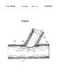
- FIG. 3is a cross-sectional view of the apparatus of FIG. 2 showing the position of elements during fabrication of a lateral seal for a 60° wye lateral connection;
- FIG. 4is a perspective view of the lateral seal fabricated with the apparatus of FIG. 2 prior to removal of excess tubular material;
- FIG. 5is a cross-sectional view showing the orientation of element of the apparatus of FIG. 2 when forming a lateral seal for a 45° wye lateral connection;
- FIG. 6is a cross-sectional view showing the orientation of element of the apparatus of FIG. 2 when forming a lateral seal for a 90° lateral connection;
- FIG. 7is a plan view illustrating the first step in the process of impregnating the lateral seal of FIG. 1 with a curable resin in a container;
- FIG. 8shows the lateral seal being wet out with resin as the vacuum is drawn on the sealed container
- FIG. 9is a plan view showing the flexible lateral seal of FIG. 1 fully impregnated and encased within the container;
- FIG. 10is a schematic illustration of the lateral seal of FIG. 1 being installed at the lateral connection.
- FIG. 11is a cross-sectional view showing the position of the lateral seal of FIG. 1 after installation.
- Seal 11constructed and arranged in accordance with the invention as shown. Seal 11 will be used for lining the intersection of a main pipeline 51 and a connecting lateral pipeline 52 as shown in FIG. 10.
- Seal 11includes a relatively short tubular section 12 and a flat brim section 13, which are bonded together by an adhesive bond 14.
- Tubular section 12is formed of a substantially planar piece of flexible resin impregnable material 16, such as a needled felt. Resin-impregnable material 16 is coated with a smooth impermeable layer 17 on one surface.
- Tubular section 13is joined together by a plurality of stitches 19 such that when the tubular section 12 is inflated to its circular form the edges are in butting contact.
- An impregnable tape or sealis disposed over stitches 19 to maintain the impermeable characteristic of impermeable layer 17.
- Brim section 13is formed of a layer of resin impregnable material 21, such as a needled felt. Resin impregnable material layer 21 is coated with a smooth impermeable layer 22 on one side. Smooth coating 17 and 22 will become the inside of lateral seal 11 facing the interior of pipelines 51 and 52 after installation.
- tubular section 12is bonded to ring section 13 by a bond 14 at an angle corresponding to the angle of the intersection of lateral 52 and main pipeline 51 desired to be sealed.
- Selection of materials for resin impregnable materials 16 and 21 and smooth impermeable layers 17 and 22is dependent on the end use of the pipelines and ability of the particular resin impregnable material to transmit the radiant energy used to cure resin in seal 11.
- the radiant energy used for curingis visible light.
- acrylic or polypropylene fibersare chosen as the resin impregnable materials 16 and 21 because when these fibers are wetted with a light curable resin, it has the ability to transmit sufficient visible light to cure the resin.
- FIG. 2is an exploded perspective view of the components forming lateral seal 11 and an apparatus 23 for use in fabricating lateral seal 11 in accordance with the invention is shown in FIG. 3.
- a pipe template 24is used to provide a model for the actual intersection of mainline conduit and lateral pipeline to be sealed.
- Pipe template 24is in the form of a pipe having an outside diameter dimension corresponding to the inside diameter of the main pipeline to be sealed and an opening 26 corresponding to the size, shape and angle of the opening of the lateral pipeline to be sealed.
- pipe template 24will have at least one opening 26 corresponding to each of the different lateral intersection angles that are used, which are typically 45°, 60° and 90°.
- index line 27is marked onto the surface of pipe template 24 extending along the longitudinal axis of pipe template 24 from the front and back ends of each opening 26, along the center line of each opening 26. Index line 27 will be used to align shaped ring section 13 properly prior to formation of lateral seal 11.
- Ring section 13is formed by placing a swatch of liner material having resin impregnable layer 21 with impermeable coating 22 over opening 26 in pipe template 24 whose size and angle matches that of the lateral intersection to be sealed. A hole is cut through the swatch conforming to the shape of opening 26 in pipe template 24. The swatch is then cut around the opening such that ring section 13 is formed, with an inner dimension and shape similar to opening 26 in template 24.
- the width of ring section 13, i.e., the distance between the inner diameter and the outer diameter,should be set to give sufficient coverage of the area within the main pipeline between a previously installed lining in a main pipeline and the lateral pipeline where the seal is to be applied. This width is usually between about 1 to 4 inches, and preferably 2 to 3 inches, but may be larger or smaller as desired such that leakage at the intersection of lateral and main pipeline liner is prevented.
- Ring section 13 cut from the swatch of liner materialis generally not circular. This is due to the cylindrical surface shape of pipe template 24 and the intersection of the two cylindrical pipes.
- an index line 28is inscribed onto resin impregnable layer 21 of ring section 13 in alignment with pipe template index line 27. Index lines 27 and 28 are used to align the components during formation of seal 11, as described in more detail below.
- a properly sized ring section 13is placed about the particular opening 26 in pipe template 24 that most closely approximates the size, shape and angle of the lateral connection desired to be sealed. Ring section 13 is placed such that index line 28 is in alignment and matches up with template index lines 27. This enables ring section 13 to fit properly and closely about opening 26. Impermeable layer 22 of ring section 13 should be placed facing towards template 24.
- Tubular section 12which is longer than needed for the final dimension of seal 11 is then inserted through ring 13 and opening 26 at an angle corresponding to that of the lateral connection to be sealed, as shown in FIG. 3.
- a bottom section 31 of tubular section 12is within pipe template 24.
- Tubular section 12is oriented such that impermeable layer 17 is on the inside and resin impregnable layer 16 is on the outside.
- An elongated inflatable plug 29is placed inside tubular section 12 and through opening 26, and expanded. When inflatable plug 29 is inflated, tubular section 13 is expanded to its full diameter such that resin impregnable layer 16 contacts the inner edge of ring section 13, which is seated on the surface of template 24 about opening 26. When in this position, ring section 13 is bonded to tubular section 12 by glue, heat or any other suitable manner at bond line 14, as shown in FIG. 3.
- Plug 29is then deflated and removed.
- the combined tubular section 12 and ring section 13, shown in FIG. 4,remain bonded to each other at bond line 14.
- What remains, as shown in FIG. 1,is flexible lateral seal 11 in the form of a top hat, in which the remaining, upper portion of tubular section 12 forms the cylindrical crown and ring section 13 forms the flange-like brim.
- FIGS. 5 and 6show additional templates 24' and 24" are shown in FIGS. 5 and 6, respectively.
- FIG. 5shows an external view of tubular section 12' inserted at a 45° angle through ring section 13' in a pipe template 24' having an opening shaped for a 45° intersection.
- FIG. 5also shows elongated inflatable plug 29 inflated within tubular section 12' and having expanded tubular section 12' which is bonded at a bond line 14' to inside edge 35 of ring section 13'.
- FIG. 6shows a similar external view, but wherein a tubular section 12" has been inserted through an annular ring section 13" in a pipe template 24" having an opening dimensional for an intersection at an angle of 90°.
- lateral seal 11Prior to installation, lateral seal 11 must be fully impregnated with a thermosetting resin. As illustrated in FIG. 7, this is accomplished first by sealing the cylindrical end of tubular portion 13 of lateral seal 11 using a sealing tape 32, such as duct tape or the like. Lateral seal 11 is then placed within a container 33 having a predetermined quantity of a selected resin 34. This permits resin impregnable material of lateral seal 11 to be completely wetted with resin 34. It is preferable that container 33 be transparent so that confirmation of wet out can be accomplished visually, and resin can be massaged fully into the material.
- a vacuum hose 36is placed into the opening of container 33, and a seal 37 is secured thereabout.
- Hose 36is connected to a vacuum pump (not shown) to create a vacuum within container 33.
- resin 34is then massaged upwardly through resin absorbent layers 16 and 21 of lateral seal 11 to light in order to completely wet out tubular portion 12 and brim portion 13.
- a seal 38is used to seal container 33 as shown in FIG. 9.
- lateral seal 11is ready for installation.
- resin 34is a light curable resin and exposure of the resin-impregnated lateral seal 11 to light will likely cause curing.
- seal 11 contained within transparent container 33must be further secured within an opaque blanket, foil or secondary container 39 which is shown sealed by a seal 41. Seal 11 will thus be protected against premature curing by inadvertent exposure to light prior to installation at the conduit/lateral junction to be sealed.
- brim 13sits along the interior surface of main pipeline 51 and will bond to previously installed lining 53.
- Tubular portion 12extends a desired distance into lateral pipeline 52.
- Lateral seal 11is installed after an opening 62 is cut in lining 53. Once seal 11 is installed, it will be more difficult for ground water at remote fracture 54 in FIG. 10 from entering relined main pipeline 51 at opening 62. This has been a shortcoming because opening 62 was generally formed using a remote cutting tool with a router bit or the like leaving a rough opening. This has created a long felt need for providing an effective lateral seal to seal the connection between a lateral pipe 52 and main pipeline 51.
- Apparatus 101includes bladder cartridge 102 including an inflatable bladder 103 with a radially extending bladder arm 110 mounted on a substantially rigid bladder frame 104 having a base 131 and skeleton 139 between identical cup shaped proximal and distal end plates 105 with side wall sections 106.
- Bladder 103is mounted to side wall sections 106 of proximal and distal end plates 105 and 105', respectively by tape or banding 140.
- Bladder frame 104 carrying bladder cartridge 102is mounted in a delivery sled 107 equipped with a proximal positioning motor 108 and a separately operable distal lift motor 109 and a TV camera 111 mounted on a motor arm 112 by a spring 113.
- a visible light box 141 including lamps 142Prior to securing bladder 103 to bladder frame 104, a visible light box 141 including lamps 142 are secured to base plate 131 of bladder frame 104.
- lamps 142 emitting visible light within the range of about 400 to 600 nanometersare utilized.
- lamps 142are 1000 watt halogen lamps having a tungsten halide filament mounted in substantially rectangular light box 141. These lamps emit light rich in the 470 nanometer region.
- Box 141has a transparent glass top plate 143.
- Matching electrical connections 144are provided both ends of light box 141 so that light bladder frame assembly 102 may be inserted into delivery sled 107 in either direction as discussed above.
- lateral seal 11When installing lateral seal 11 in lateral pipeline 52, such as shown in FIG. 11 which intersects main pipeline 51 at a wye or angle, it is desirable to provide sufficient light extending into lateral pipeline 52 to insure that the resin in tubular section 13 is fully cured.
- an additional visible light emitting lamp 146is provided at one end light box 141 projecting upwardly at an angle into the location of lateral 52.
- a small 300 watt projector lampis aimed towards the dark or short side of wye fitting.
- the cavity between light box 141 and skeleton 139 at the opposite side of light box 141is open so that tubular portion 13 of lateral seal 11 can tucked within the interior of bladder frame 102 as seal 11 is loaded for installation.
- Motor arm 112is mounted on rack of a rack and pinion lift bar 114 which is operably coupled to proximal positioning motor 108.
- Proximal positioning motor 108provides lift to lift bar 114 for elevating the proximal end of bladder cartridge 102 at a proximal lug 117 connection at proximal end plate 105 and also includes a rotational motor (not shown) for rotating motor arm 112 radially for positioning seal 11 at the entrance to lateral 52.
- Distal lift motor 109also includes a lift arm 116 which includes a rack and pinion for lifting or lowering the distal end of bladder cartridge 102 by distal lug connection 117 at distal end plate 105.
- Delivery sled 107includes a base plate 118 for supporting motors 108 and 109.
- Base plate 118is mounted on a pair of sled runners 119 at each end for displacement of apparatus 101 along the length of existing main pipeline 51 at the location of lateral 52.
- Positioningis facilitated by using TV camera 111 which is controlled remotely by a cable 120.
- TV camera 111is mounted on spring 113 to permit displacement downward as lift motor 108 lifts bladder cartridge 102 into position adjacent to the opening to lateral 52.
- Proximal end plate 105includes at least one inlet port 126 which provides access to the interior of bladder cartridge 102 for providing a source of pressure to inflate bladder 103 and power a source of radiant energy in the interior of bladder 103 for initiating the cure of resin impregnated in impermeable layer 16 and 21 of seal 11.
- pressureis provided by an air/vacuum hose 126' coupled to inlet port 126.
- a power line 127'is coupled to another inlet port 127 to provide power to a source of radiant energy within bladder 103.
- Corresponding ports 128 and 129are provided in distal end plate 105'. This is beneficial as it permits utilizing one port 128 to allow air to escape when the pressurized fluid is air.
- watercan also be expelled through distal output 129.
- thismay not be wholly desirable since the portion of the main pipeline being lined is generally bypassed from the remainder of the pipe system.
- bladder cartridge 102can be inserted into delivery sled 107 in either direction. This greatly facilitates installation of laterals which intersect main pipeline 51 in opposed directions.
- bladder arm 110As pressurized air is applied to the interior of bladder 103, bladder arm 110 which was tucked within bladder 103 everts through the opening in brim 13 of seal 11 forcing tubular portion 12 of seal 11 to evert into lateral 52. Seal 11 is held in place as long as bladder 103 and arm 110 remain inflated.
- air or water under pressurecan be utilized to inflate bladder 103.
- waterWhen water is utilized and provides heat as the source of radiant energy for initiating the cure, and additional port 129 in distal plate 105 is used to permit the water to circulate.
- lateral seal 11When lateral seal 11 is positioned in place and bladder 103 is inflated, energy is applied to initiate cure of the resin.
- energyis visible light cool air supplied by air hose 126' is circulated through bladder 103. This removes the heat generated by the exothermic cure reaction and the substantial heat generated by the halogen lamps as the visible light source.
- An adjustable pressure relief valve 125such as a Nupro B-8CPA2 regulator which is adjustable between 3 to 50 psi with a 1/2 inch male thread is mounted in port 128. By inputting air at port 126 at about 20 psi through hose 126' and setting valve 125 at 4 psi, 4 psi pressure can be maintained in bladder 103 to keep it inflated.
- a vacuumis drawn through air hose 126' now coupled to a vacuum pump to deflate bladder 103.
- Application of the vacuum to bladder 103withdraws arm 110 from lateral 52 and causes it to deinvert into bladder 103. Withdrawal of arm 110 from within seal 11 is thus accomplished without use of a rope or other pulling mechanism which would otherwise present an opaque region and cast a shadow which would interfere with light projected into lateral 52 during the cure cycle.
- bladder cartridge 102as a separate removable unit from delivery sled 107 results in several significant operational advantages. This allows loading of a second impregnated lateral seal 11 on a second bladder cartridge 102 as a first is being used to install and cure at one lateral location. As soon as the lateral connection being installed is completed, delivery sled 107 is removed from main pipeline 51, spent bladder cartridge 102 is removed and a second bladder cartridge 102 previously loaded with resin impregnated seal 11 is then inserted at both lug connections 117 and a second lateral installation can begin immediately. This is a significant time saving advantage. This is particularly true when a visible light cure resin is used.
- FIG. 11shows cured-in-place lateral seal 11 with tubular portion 12 within lateral 52 and ring portion 13 of lateral seal 11 in place in main pipeline 51.
- bladder 103When a light curable resin composition is used to impregnate seal 11, lamps emitting visible light having a wave length in the range of about 400 to 600 nanometers are mounted within bladder 68.
- bladder 103must be fabricated from a flexible, transmissible material, such as silicone, to provide maximum light for curing seal 11.
- the resinmay be impregnated with a modified polyester or epoxy which is light curable and has an appropriate light transmissibility as discussed in U.S. Pat. No. 4,581,247, the contents of which are incorporated herein by reference.
- Acrylate substituted epoxy resinsmay be used alone or blended with viscosity modifiers, such as glycols, and initiated by a photo-bleaching visible light initiator.
- the resin impregnable materialis preferable an acrylic felt.
- Resin impregnable material 16 and 21is typically an acrylic or polypropylene felt or a glass fibrous matte which will transmit the visible light when emitted by the lamps within bladder 103.
- Resin 34is a composition of a free radical light cureable resin admixed with an effective amount of a visible light, photo-bleaching initiator system and optionally performance enhancing fillers which can be impregnated into resin impregnable layers 17 and 22 and subsequently cured to a suitable depth.
- the resincan be selected from oligoeters of mono-ethylenically unsaturated urethanes, epoxies, polyesters and acrylics.
- the resinis an epoxy acrylate resin which is a diglycydyl ether of bisphenol A which has been esterified with acrylic acid or methacrylic acid and which may include an ethylenically mono-unsaturated compound as a viscosity modifier admixed with an effective amount of a photo-bleaching visible light initiator system.
- the photo-bleaching initiator systemincludes a visible light sensitizer which is a fluorone derivative admixed with a hydrogen donor compound.
- the visible light curable sensitizer compoundincludes a fluorone derived material.
- the preferred fluorone derivativeis 5,7-diiodo-3-butoxy-6-fluorone.
- the fluorone derivative sensitizeris mixed with an electron donating coinitiator, such as a tertiary amine to form the photoinitiator system.
- Triethanolaminehas been found to enhance the photo-bleaching effect of the fluorone sensitizer.
Landscapes
- Engineering & Computer Science (AREA)
- General Engineering & Computer Science (AREA)
- Mechanical Engineering (AREA)
- Lining Or Joining Of Plastics Or The Like (AREA)
Abstract
Description
Claims (11)
Priority Applications (2)
| Application Number | Priority Date | Filing Date | Title |
|---|---|---|---|
| US08/979,272US5915419A (en) | 1997-11-26 | 1997-11-26 | Cured in place lateral seal for relining of pipelines and method of manufacture |
| US09/342,705US6044867A (en) | 1997-11-26 | 1999-06-29 | Method and apparatus for fabricating a flexible lining with flexible collar for lining lateral pipelines |
Applications Claiming Priority (1)
| Application Number | Priority Date | Filing Date | Title |
|---|---|---|---|
| US08/979,272US5915419A (en) | 1997-11-26 | 1997-11-26 | Cured in place lateral seal for relining of pipelines and method of manufacture |
Related Child Applications (1)
| Application Number | Title | Priority Date | Filing Date |
|---|---|---|---|
| US09/342,705DivisionUS6044867A (en) | 1997-11-26 | 1999-06-29 | Method and apparatus for fabricating a flexible lining with flexible collar for lining lateral pipelines |
Publications (1)
| Publication Number | Publication Date |
|---|---|
| US5915419Atrue US5915419A (en) | 1999-06-29 |
Family
ID=25526813
Family Applications (2)
| Application Number | Title | Priority Date | Filing Date |
|---|---|---|---|
| US08/979,272Expired - LifetimeUS5915419A (en) | 1997-11-26 | 1997-11-26 | Cured in place lateral seal for relining of pipelines and method of manufacture |
| US09/342,705Expired - LifetimeUS6044867A (en) | 1997-11-26 | 1999-06-29 | Method and apparatus for fabricating a flexible lining with flexible collar for lining lateral pipelines |
Family Applications After (1)
| Application Number | Title | Priority Date | Filing Date |
|---|---|---|---|
| US09/342,705Expired - LifetimeUS6044867A (en) | 1997-11-26 | 1999-06-29 | Method and apparatus for fabricating a flexible lining with flexible collar for lining lateral pipelines |
Country Status (1)
| Country | Link |
|---|---|
| US (2) | US5915419A (en) |
Cited By (47)
| Publication number | Priority date | Publication date | Assignee | Title |
|---|---|---|---|---|
| US6082411A (en)* | 1998-11-20 | 2000-07-04 | Tele Environmental Systems | Apparatus and method for the robotic repairing of an underground pipe junction |
| US6206049B1 (en)* | 1998-11-20 | 2001-03-27 | Tele Environmental Systems | Apparatus and method for the robotic repairing of an underground pipe junction with removable heating element |
| US6276398B1 (en)* | 2000-06-14 | 2001-08-21 | Frederick Lange | Inflatable packer for repairing conduits |
| WO2001081805A3 (en)* | 2000-04-24 | 2002-05-30 | Ihc Rehabilitation Products | Method of forming repair material for conduit interface area and for repairing a non-linear conduit with a fiber repair material |
| US6427725B1 (en)* | 2000-08-14 | 2002-08-06 | Vanderlans Gerald J. | Pipeline lateral packer and felt combinations and methods therefor |
| US20030213556A1 (en)* | 2000-02-02 | 2003-11-20 | Blackmore Richard D. | Apparatus, methods, and liners for repairing conduits |
| US20040016467A1 (en)* | 2001-04-24 | 2004-01-29 | Blackmore Mark D. | Method of forming repair material for conuit interface area and for repairing a non-linear conduit with a fiber repair material |
| US6688337B2 (en) | 2001-12-19 | 2004-02-10 | Robert M. Ward | Apparatus and method for the robotic repairing of an underground pipe junction with a flexible patch mechanism |
| US6732763B2 (en) | 2002-05-24 | 2004-05-11 | Lantor, Inc. | Stretch-resistant pipe liner |
| US20050133105A1 (en)* | 2003-11-12 | 2005-06-23 | In.Tec S.R.L. | Device and a process for non-destructive repair of a side inlet pipe of a main sewer of a draining pipe |
| US20050189028A1 (en)* | 2004-02-26 | 2005-09-01 | Irathane Systems, Inc. | Rubber polyurethane line |
| US20050241713A1 (en)* | 2004-04-28 | 2005-11-03 | Shonan Gosei-Jushi Seisakusho K.K. | Method for rehabilitating an existing pipe |
| US20070261751A1 (en)* | 2006-05-09 | 2007-11-15 | William Lepola | Lateral Interface Device with Flexible Housing |
| US20070284876A1 (en)* | 2006-04-27 | 2007-12-13 | Polivka Richard C | Reinstatement of an existing connection in a lined conduit |
| US20080236692A1 (en)* | 2007-03-30 | 2008-10-02 | Lmk Enterprises, Inc. | Bladderless pipeliner and method for using same |
| US20080245433A1 (en)* | 2007-04-03 | 2008-10-09 | Darcy Warren | Lateral liner with seal |
| US20090194184A1 (en)* | 2008-02-06 | 2009-08-06 | Lmk Enterprises, Inc. | Device and method for repairing pipe |
| US20090194183A1 (en)* | 2008-02-05 | 2009-08-06 | Lmk Enterprises, Inc. | Bladder and method for cured-in-place pipe lining |
| US20090289451A1 (en)* | 2008-05-21 | 2009-11-26 | Ina Acquisition Corp. | T-Nut Assembly For Sealing An Existing Connection In A Lined Conduit |
| US20100108238A1 (en)* | 2008-11-05 | 2010-05-06 | Trelleborg Pipe Seals Duisburg Gmbh | Method and apparatus for impregnating a lining module provided with a resin-absorbing layer |
| WO2011104357A2 (en) | 2010-02-26 | 2011-09-01 | Trelleborg Pipe Seals Duisburg Gmbh | Lining element for pipeline branch repair, and method of manufacturing a lining element |
| US20110232793A1 (en)* | 2010-03-24 | 2011-09-29 | Ina Acquisition Corp. | Wedge type plug and method of plugging a lateral line |
| US20120084956A1 (en)* | 2010-10-06 | 2012-04-12 | Lmk Enterprises, Inc. | Apparatus and method for repairing the junction of a sewer main and lateral pipe |
| US20120139183A1 (en)* | 2010-12-07 | 2012-06-07 | Lmk Enterprises, Inc. | Hydrophilic end seal |
| US8240340B2 (en) | 2010-12-07 | 2012-08-14 | Lmk Enterprises, Inc. | Hydrophilic end seal |
| DE102011075404A1 (en)* | 2011-05-06 | 2012-11-08 | Trelleborg Pipe Seals Duisburg Gmbh | T-shaped calibration hose for use in packer to clean junction areas of main pipes and house connection pipes, has side pipe calibration hose's end region connected with main pipe calibration hose's connection region via connecting device |
| DE102011075403A1 (en) | 2011-05-06 | 2012-11-08 | Trelleborg Pipe Seals Duisburg Gmbh | calibration hose |
| GB2503353A (en)* | 2012-06-20 | 2013-12-25 | Fernco Environmental Ltd | Repair of pipes and pipelines |
| US8636036B2 (en) | 2010-12-07 | 2014-01-28 | Lmk Technologies, Llc | Apparatus and method for sealing pipes |
| US8640737B2 (en) | 2010-12-07 | 2014-02-04 | Lmk Technologies, Llc | Apparatus and method for sealing pipes and underground structures |
| US20140158243A1 (en)* | 2012-12-11 | 2014-06-12 | Lmk Technologies Llc | Main / lateral connection liner with resin putty mainline portion |
| US20150034199A1 (en)* | 2012-02-23 | 2015-02-05 | Sml Verwaltungs Gmbh | Lining hose for the rehabilitation of fluid-carrying line systems |
| DE202015102868U1 (en) | 2015-06-02 | 2015-06-30 | Trelleborg Pipe Seals Duisburg Gmbh | lining member |
| US20150184786A1 (en)* | 2011-09-02 | 2015-07-02 | David J. Kriens, Jr. | Snap fitting for plumbing |
| WO2015153590A1 (en)* | 2014-03-31 | 2015-10-08 | Source 1 Environmental, Llc | Apparatus and method for plugging a pipe |
| US20150338014A1 (en)* | 2010-02-26 | 2015-11-26 | Trelleborg Pipe Seals Duisburg Gmbh | Lining Element, and Method of Manufacturing a Lining Element |
| US9366375B2 (en) | 2007-08-27 | 2016-06-14 | Lmk Technologies, Llc | Device and method for repairing pipe |
| US20170122482A1 (en)* | 2014-06-13 | 2017-05-04 | Picote Oy Ltd. | Branch piece to be used in pipe renovation, and method for renovating branch point in pipe assembly |
| WO2017174079A1 (en)* | 2016-04-08 | 2017-10-12 | Sml Verwaltungs Gmbh | Device for curing a lining sleeve comprising a camera device |
| US9791089B2 (en) | 2012-03-23 | 2017-10-17 | Lmk Technologies, Llc | Method and apparatus for repairing a pipe junction |
| US10683959B2 (en) | 2017-10-17 | 2020-06-16 | Lmk Technologies, Llc | Method and apparatus for repairing a length of pipe or a main/lateral pipe junction |
| US10767805B2 (en) | 2016-07-28 | 2020-09-08 | BLD Services, LLC | Pipe lining systems and methods of use |
| US11131418B2 (en) | 2017-01-06 | 2021-09-28 | The Charles Machine Works, Inc. | Assembly for relining a junction between a branch pipeline and a main pipeline, and for relining a part of or the whole branch pipeline |
| US11391406B2 (en) | 2019-11-11 | 2022-07-19 | The Charles Machine Works, Inc. | System and method for repairing an underground pipeline |
| US11566742B2 (en) | 2017-08-18 | 2023-01-31 | Moray Group, Llc | Method, apparatus and system for lining conduits |
| US11643801B1 (en)* | 2021-12-29 | 2023-05-09 | Gulf Coast Underground, LLC | System and method for sealing an annular space of a sewer connection line |
| US12439493B2 (en) | 2023-02-10 | 2025-10-07 | The Charles Machine Works, Inc. | Dynamic temperature regulation system for a light head |
Families Citing this family (8)
| Publication number | Priority date | Publication date | Assignee | Title |
|---|---|---|---|---|
| US6337114B1 (en)* | 1992-09-10 | 2002-01-08 | Insituform (Netherlands) B.V. | Flexible lining with flexible collar for lining lateral pipelines |
| US6484757B1 (en) | 2002-03-19 | 2002-11-26 | Liqui-Force Sewer Services Inc. | Method and device for lining a lateral sewer pipe |
| ITMI20030339A1 (en)* | 2003-02-26 | 2004-08-27 | Pranha 50 Ltda | METHOD, APPARATUS AND DEVICES FOR THE RENOVATION OF PIPES BY INTRODUCTION OF PLASTIC PIPES. |
| JP5534585B2 (en)* | 2010-01-29 | 2014-07-02 | 株式会社湘南合成樹脂製作所 | Branch pipe lining manufacturing method |
| US20120007714A1 (en) | 2010-07-07 | 2012-01-12 | Muehlin Michael | Sewer pipe repair liner with radio-frequency identification transponder and method of using same |
| US20120006439A1 (en)* | 2010-07-08 | 2012-01-12 | Lmk Enterprises, Inc. | Method and means for forming a liner |
| US11173634B2 (en) | 2018-02-01 | 2021-11-16 | Ina Acquisition Corp | Electromagnetic radiation curable pipe liner and method of making and installing the same |
| US10704728B2 (en) | 2018-03-20 | 2020-07-07 | Ina Acquisition Corp. | Pipe liner and method of making same |
Citations (30)
| Publication number | Priority date | Publication date | Assignee | Title |
|---|---|---|---|---|
| US2944994A (en)* | 1954-07-07 | 1960-07-12 | Robertson Co H H | Method of making transparent unsaturated polyester-styrene-glass fiber composition |
| US3804663A (en)* | 1971-05-26 | 1974-04-16 | Dow Chemical Co | Method of internally coating rigid or semi-rigid plastic containers |
| US4009063A (en)* | 1970-09-22 | 1977-02-22 | Insituform (Pipes And Structures) Limited | Method of lining a pipe |
| US4064211A (en)* | 1972-12-08 | 1977-12-20 | Insituform (Pipes & Structures) Ltd. | Lining of passageways |
| US4135958A (en)* | 1974-01-25 | 1979-01-23 | Insituform International Inc. | Method of lining a passageway with a resin absorbent tube |
| GB2041147A (en)* | 1979-01-22 | 1980-09-03 | Fusion Equipment Ltd | Renovating sewers |
| EP0025359A1 (en)* | 1979-09-11 | 1981-03-18 | Scott Bader Company Limited | Preimpregnated materials and methods of making and using them |
| EP0039838A1 (en)* | 1980-04-30 | 1981-11-18 | Dainippon Ink And Chemicals, Inc. | Greenhouse |
| US4425287A (en)* | 1979-08-04 | 1984-01-10 | Basf Aktiengesellschaft | Production of moldings from unsaturated polyester resins |
| US4434115A (en)* | 1981-02-18 | 1984-02-28 | Insituform International, Inc. | Method for remote lining of side connections |
| US4439469A (en)* | 1981-03-05 | 1984-03-27 | Insituform International N.V. | Formation of a lining in pipelines |
| US4518247A (en)* | 1982-06-11 | 1985-05-21 | Olympus Optical Company Limited | Apparatus for forming image by developing charge latent image with toner |
| US4581247A (en)* | 1984-01-05 | 1986-04-08 | Insituform International N.V. | Lining of pipelines and passageways |
| US4680066A (en)* | 1984-07-13 | 1987-07-14 | Insituform Group Limited | Lining of pipelines or passageways |
| US4991006A (en)* | 1990-03-08 | 1991-02-05 | Insituform Licensees, B. V. | Apparatus using an everted hose for inspecting the interior of a lateral pipeline |
| DE3929558A1 (en)* | 1989-09-06 | 1991-03-07 | Hans Mueller | Sealing joint between mains drain and house connection - involves resin-impregnated insert, placed into house pipe without excavation of ground |
| US5018545A (en)* | 1990-01-19 | 1991-05-28 | Insituform Of North America, Inc. | Apparatus for cleaning interior of a lateral pipeline |
| WO1991007619A1 (en)* | 1989-11-21 | 1991-05-30 | Wavin B.V. | Thermoplastic saddle in two parts for repairing or renovating a pipeline with branch pipe and repaired or renovated pipe with a saddle |
| WO1991016568A1 (en)* | 1990-04-23 | 1991-10-31 | Insituform Group Limited | Improvements relating to the lining of pipelines or passageways |
| DE4031949A1 (en)* | 1990-10-09 | 1992-04-16 | Bauunternehmung Bergfort Gmbh | Renovation of main sewer and branch pipe - involves fitting liners made of flexible plastics tube |
| US5108533A (en)* | 1989-10-10 | 1992-04-28 | Long Technologies, Inc. | Method and combination for installing a liner within a service pipe transversely connected to a main pipe |
| EP0518521A2 (en)* | 1991-05-31 | 1992-12-16 | GET Inc. | A liner assembly for lining branch pipes and a method for manufacturing the liner assembly |
| US5395862A (en)* | 1992-12-09 | 1995-03-07 | Spectra Group Limited, Inc. | Photooxidizable initiator composition and photosensitive materials containing the same |
| WO1995008737A1 (en)* | 1993-09-25 | 1995-03-30 | Ina Acquisition Corp. | Improvements relating to the lining of pipelines and passageways |
| US5451343A (en)* | 1991-05-20 | 1995-09-19 | Spectra Group Limited, Inc. | Fluorone and pyronin y derivatives |
| US5514519A (en)* | 1991-10-02 | 1996-05-07 | Spectra Group Limited, Inc. | Production of three-dimensional objects |
| US5606171A (en)* | 1994-05-05 | 1997-02-25 | Spectra Group Limited, Inc. | Method for determining thickness, degree of cure and other properties of a polymeric coating or film |
| US5639802A (en)* | 1991-05-20 | 1997-06-17 | Spectra Group Limited, Inc. | Cationic polymerization |
| US5692543A (en)* | 1992-12-07 | 1997-12-02 | Insituform (Netherlands) B.V. | Lining of lateral pipelines with a liner having a sealing collar |
| US5807025A (en)* | 1993-05-05 | 1998-09-15 | Klug Kanal-, Leitungs- und Umweltsanierungs-Gesellschaft M.B.H | Process for lining a channel and fitting and withdrawal slide for implementing it |
Family Cites Families (9)
| Publication number | Priority date | Publication date | Assignee | Title |
|---|---|---|---|---|
| US3946761A (en)* | 1974-06-24 | 1976-03-30 | The Penetryn System, Inc. | Packer for sealing pipe leaks |
| SE435866B (en)* | 1983-04-06 | 1984-10-22 | Vj System Ab | PROCEDURE AND DEVICE FOR LINING OF PIPES, WITH A FLEXIBLE, HARDENABLE PLASTIC CONTAINING HOSE |
| DE3922351A1 (en)* | 1989-07-07 | 1991-01-10 | Jt Elektronik Gmbh | METHOD FOR REFURBISHING DRAIN PIPES USING A RESINATED INTERNAL PIPE |
| GB9007719D0 (en)* | 1990-04-05 | 1990-06-06 | Subterra Ltd | Lining conduits |
| DE4207038C2 (en)* | 1992-03-06 | 1994-12-01 | Mueller Hans | Packer for lining the transition area between a main water pipe and a confluent house connection pipe |
| US5609439A (en)* | 1992-03-06 | 1997-03-11 | Kmg Kanal-Muller-Gruppe International Gmbh & Co. Kg | Method of and apparatus for repairing and sealing junctions between mains and branch pipes |
| DK0564741T3 (en)* | 1992-04-07 | 1999-07-19 | Ashimori Ind Co Ltd | Method and apparatus for repairing a pipeline and suitable repair material |
| US5451284A (en)* | 1992-12-25 | 1995-09-19 | Nippon Kokan Koji Kabushiki Kaisha | Self-mobile work vehicle moveable through pipeline and method and apparatus for lining interconnecting branch pipe using the vehicle |
| JP2564092B2 (en)* | 1993-09-28 | 1996-12-18 | 株式会社湘南合成樹脂製作所 | Branch pipe lining method |
- 1997
- 1997-11-26USUS08/979,272patent/US5915419A/ennot_activeExpired - Lifetime
- 1999
- 1999-06-29USUS09/342,705patent/US6044867A/ennot_activeExpired - Lifetime
Patent Citations (36)
| Publication number | Priority date | Publication date | Assignee | Title |
|---|---|---|---|---|
| US2944994A (en)* | 1954-07-07 | 1960-07-12 | Robertson Co H H | Method of making transparent unsaturated polyester-styrene-glass fiber composition |
| US4009063A (en)* | 1970-09-22 | 1977-02-22 | Insituform (Pipes And Structures) Limited | Method of lining a pipe |
| US3804663A (en)* | 1971-05-26 | 1974-04-16 | Dow Chemical Co | Method of internally coating rigid or semi-rigid plastic containers |
| US4064211A (en)* | 1972-12-08 | 1977-12-20 | Insituform (Pipes & Structures) Ltd. | Lining of passageways |
| US4135958A (en)* | 1974-01-25 | 1979-01-23 | Insituform International Inc. | Method of lining a passageway with a resin absorbent tube |
| GB2041147A (en)* | 1979-01-22 | 1980-09-03 | Fusion Equipment Ltd | Renovating sewers |
| US4425287A (en)* | 1979-08-04 | 1984-01-10 | Basf Aktiengesellschaft | Production of moldings from unsaturated polyester resins |
| EP0025359A1 (en)* | 1979-09-11 | 1981-03-18 | Scott Bader Company Limited | Preimpregnated materials and methods of making and using them |
| EP0039838A1 (en)* | 1980-04-30 | 1981-11-18 | Dainippon Ink And Chemicals, Inc. | Greenhouse |
| US4434115A (en)* | 1981-02-18 | 1984-02-28 | Insituform International, Inc. | Method for remote lining of side connections |
| US4439469A (en)* | 1981-03-05 | 1984-03-27 | Insituform International N.V. | Formation of a lining in pipelines |
| US4518247A (en)* | 1982-06-11 | 1985-05-21 | Olympus Optical Company Limited | Apparatus for forming image by developing charge latent image with toner |
| US4581247A (en)* | 1984-01-05 | 1986-04-08 | Insituform International N.V. | Lining of pipelines and passageways |
| US4581247B1 (en)* | 1984-01-05 | 1995-03-07 | Insituform Netherlands Bv | Lining of pipelines and passageways |
| US4680066A (en)* | 1984-07-13 | 1987-07-14 | Insituform Group Limited | Lining of pipelines or passageways |
| DE3929558A1 (en)* | 1989-09-06 | 1991-03-07 | Hans Mueller | Sealing joint between mains drain and house connection - involves resin-impregnated insert, placed into house pipe without excavation of ground |
| US5108533A (en)* | 1989-10-10 | 1992-04-28 | Long Technologies, Inc. | Method and combination for installing a liner within a service pipe transversely connected to a main pipe |
| WO1991007619A1 (en)* | 1989-11-21 | 1991-05-30 | Wavin B.V. | Thermoplastic saddle in two parts for repairing or renovating a pipeline with branch pipe and repaired or renovated pipe with a saddle |
| US5340160A (en)* | 1989-11-21 | 1994-08-23 | Wavin B.V. | Thermoplastic saddle in two parts for repairing or renovating a pipe line with branch pipe and repaired or renovated pipe with a saddle |
| US5018545A (en)* | 1990-01-19 | 1991-05-28 | Insituform Of North America, Inc. | Apparatus for cleaning interior of a lateral pipeline |
| US4991006A (en)* | 1990-03-08 | 1991-02-05 | Insituform Licensees, B. V. | Apparatus using an everted hose for inspecting the interior of a lateral pipeline |
| WO1991016568A1 (en)* | 1990-04-23 | 1991-10-31 | Insituform Group Limited | Improvements relating to the lining of pipelines or passageways |
| US5624629A (en)* | 1990-04-23 | 1997-04-29 | Insituform (Netherlands) B.V. | Installation of lateral linings with sealing collar from the main pipeline out |
| US5393481A (en)* | 1990-04-23 | 1995-02-28 | Insituform (Netherlands) Bv | Lining of pipelines or passageways |
| DE4031949A1 (en)* | 1990-10-09 | 1992-04-16 | Bauunternehmung Bergfort Gmbh | Renovation of main sewer and branch pipe - involves fitting liners made of flexible plastics tube |
| US5623080A (en)* | 1991-05-20 | 1997-04-22 | Spectra Group Limited, Inc. | Fluorone and pyronin Y derivatives |
| US5451343A (en)* | 1991-05-20 | 1995-09-19 | Spectra Group Limited, Inc. | Fluorone and pyronin y derivatives |
| US5639802A (en)* | 1991-05-20 | 1997-06-17 | Spectra Group Limited, Inc. | Cationic polymerization |
| US5329063A (en)* | 1991-05-31 | 1994-07-12 | Get, Inc. | Liner assembly for lining branch pipes and a method for manufacturing the liner assembly |
| EP0518521A2 (en)* | 1991-05-31 | 1992-12-16 | GET Inc. | A liner assembly for lining branch pipes and a method for manufacturing the liner assembly |
| US5514519A (en)* | 1991-10-02 | 1996-05-07 | Spectra Group Limited, Inc. | Production of three-dimensional objects |
| US5692543A (en)* | 1992-12-07 | 1997-12-02 | Insituform (Netherlands) B.V. | Lining of lateral pipelines with a liner having a sealing collar |
| US5395862A (en)* | 1992-12-09 | 1995-03-07 | Spectra Group Limited, Inc. | Photooxidizable initiator composition and photosensitive materials containing the same |
| US5807025A (en)* | 1993-05-05 | 1998-09-15 | Klug Kanal-, Leitungs- und Umweltsanierungs-Gesellschaft M.B.H | Process for lining a channel and fitting and withdrawal slide for implementing it |
| WO1995008737A1 (en)* | 1993-09-25 | 1995-03-30 | Ina Acquisition Corp. | Improvements relating to the lining of pipelines and passageways |
| US5606171A (en)* | 1994-05-05 | 1997-02-25 | Spectra Group Limited, Inc. | Method for determining thickness, degree of cure and other properties of a polymeric coating or film |
Non-Patent Citations (2)
| Title |
|---|
| Reexamination Certificate (2498 th ) for United States Patent No. B1 4,581,247; Issued Mar. 7, 1995.* |
| Reexamination Certificate (2498th) for United States Patent No. B1 4,581,247; Issued Mar. 7, 1995. |
Cited By (99)
| Publication number | Priority date | Publication date | Assignee | Title |
|---|---|---|---|---|
| US6206049B1 (en)* | 1998-11-20 | 2001-03-27 | Tele Environmental Systems | Apparatus and method for the robotic repairing of an underground pipe junction with removable heating element |
| US6082411A (en)* | 1998-11-20 | 2000-07-04 | Tele Environmental Systems | Apparatus and method for the robotic repairing of an underground pipe junction |
| US7073536B2 (en) | 2000-02-02 | 2006-07-11 | Verline Inc | Apparatus, methods, and liners for repairing conduits |
| US20030213556A1 (en)* | 2000-02-02 | 2003-11-20 | Blackmore Richard D. | Apparatus, methods, and liners for repairing conduits |
| WO2001081805A3 (en)* | 2000-04-24 | 2002-05-30 | Ihc Rehabilitation Products | Method of forming repair material for conduit interface area and for repairing a non-linear conduit with a fiber repair material |
| US6276398B1 (en)* | 2000-06-14 | 2001-08-21 | Frederick Lange | Inflatable packer for repairing conduits |
| US6427725B1 (en)* | 2000-08-14 | 2002-08-06 | Vanderlans Gerald J. | Pipeline lateral packer and felt combinations and methods therefor |
| US20040016467A1 (en)* | 2001-04-24 | 2004-01-29 | Blackmore Mark D. | Method of forming repair material for conuit interface area and for repairing a non-linear conduit with a fiber repair material |
| US6688337B2 (en) | 2001-12-19 | 2004-02-10 | Robert M. Ward | Apparatus and method for the robotic repairing of an underground pipe junction with a flexible patch mechanism |
| US6732763B2 (en) | 2002-05-24 | 2004-05-11 | Lantor, Inc. | Stretch-resistant pipe liner |
| US20050133105A1 (en)* | 2003-11-12 | 2005-06-23 | In.Tec S.R.L. | Device and a process for non-destructive repair of a side inlet pipe of a main sewer of a draining pipe |
| US20050189028A1 (en)* | 2004-02-26 | 2005-09-01 | Irathane Systems, Inc. | Rubber polyurethane line |
| US9885448B2 (en) | 2004-02-26 | 2018-02-06 | Irathane Systems, Inc. | Rubber polyurethane liner |
| US20050241713A1 (en)* | 2004-04-28 | 2005-11-03 | Shonan Gosei-Jushi Seisakusho K.K. | Method for rehabilitating an existing pipe |
| US7028716B2 (en)* | 2004-05-28 | 2006-04-18 | Shonan Gosei-Jushi Seisakusho K.K. | Method for rehabilitating an existing pipe |
| US8015695B2 (en) | 2006-04-27 | 2011-09-13 | Ina Acquisition Corp. | Reinstatement of an existing connection in a lined conduit |
| US20070284876A1 (en)* | 2006-04-27 | 2007-12-13 | Polivka Richard C | Reinstatement of an existing connection in a lined conduit |
| US20070261751A1 (en)* | 2006-05-09 | 2007-11-15 | William Lepola | Lateral Interface Device with Flexible Housing |
| US7628177B2 (en)* | 2006-05-09 | 2009-12-08 | Energy Maintenance Service I LLC | Lateral interface device with flexible housing |
| US7845372B2 (en) | 2007-03-30 | 2010-12-07 | Lmk Enterprises, Inc. | Bladderless pipeliner and method for using same |
| US20080236692A1 (en)* | 2007-03-30 | 2008-10-02 | Lmk Enterprises, Inc. | Bladderless pipeliner and method for using same |
| US8316892B2 (en)* | 2007-04-03 | 2012-11-27 | Liqui-Force Sewer Services Inc. | Lateral liner with seal |
| US20080245433A1 (en)* | 2007-04-03 | 2008-10-09 | Darcy Warren | Lateral liner with seal |
| US9366375B2 (en) | 2007-08-27 | 2016-06-14 | Lmk Technologies, Llc | Device and method for repairing pipe |
| US11555572B2 (en) | 2007-08-27 | 2023-01-17 | Lmk Technologies, Llc | Device and method for repairing pipe |
| US12253203B2 (en) | 2007-08-27 | 2025-03-18 | Lmk Technologies, Llc | Device and method for repairing pipe |
| US20090194183A1 (en)* | 2008-02-05 | 2009-08-06 | Lmk Enterprises, Inc. | Bladder and method for cured-in-place pipe lining |
| US20090194184A1 (en)* | 2008-02-06 | 2009-08-06 | Lmk Enterprises, Inc. | Device and method for repairing pipe |
| US7987873B2 (en) | 2008-02-06 | 2011-08-02 | Lmk Enterprises, Inc. | Device and method for repairing pipe |
| US20090289451A1 (en)* | 2008-05-21 | 2009-11-26 | Ina Acquisition Corp. | T-Nut Assembly For Sealing An Existing Connection In A Lined Conduit |
| DE102008055943A1 (en) | 2008-11-05 | 2010-05-12 | Trelleborg Pipe Seals Duisburg Gmbh | Method and apparatus for impregnating a lining module equipped with a resin-absorbable layer |
| DE102008055943B4 (en)* | 2008-11-05 | 2012-09-06 | Trelleborg Pipe Seals Duisburg Gmbh | A method of impregnating a lining module equipped with a resin-absorbable layer |
| US20100108238A1 (en)* | 2008-11-05 | 2010-05-06 | Trelleborg Pipe Seals Duisburg Gmbh | Method and apparatus for impregnating a lining module provided with a resin-absorbing layer |
| EP2184527A2 (en) | 2008-11-05 | 2010-05-12 | Trelleborg Pipe Seals Duisburg GmbH | Method and apparatus for impregnating a lining module provided with a resin-absorbing layer |
| EP2184527A3 (en)* | 2008-11-05 | 2011-03-09 | Trelleborg Pipe Seals Duisburg GmbH | Method and apparatus for impregnating a lining module provided with a resin-absorbing layer |
| US8043656B2 (en) | 2008-11-05 | 2011-10-25 | Trelleborg Pipe Seals Duisburg Gmbh | Method and apparatus for impregnating a lining module provided with a resin-absorbing layer |
| WO2011104357A2 (en) | 2010-02-26 | 2011-09-01 | Trelleborg Pipe Seals Duisburg Gmbh | Lining element for pipeline branch repair, and method of manufacturing a lining element |
| US20150338014A1 (en)* | 2010-02-26 | 2015-11-26 | Trelleborg Pipe Seals Duisburg Gmbh | Lining Element, and Method of Manufacturing a Lining Element |
| US9568139B2 (en)* | 2010-02-26 | 2017-02-14 | Trelleborg Pipe Seals Duisburg Gmbh | Lining element and method of manufacturing a lining element |
| US9689522B2 (en)* | 2010-02-26 | 2017-06-27 | Trelleborg Pipe Seals Duisburg Gmbh | Lining element, and method of manufacturing a lining element |
| US20120312407A1 (en)* | 2010-02-26 | 2012-12-13 | Michael Muhlin | Lining element and method of manufacturing a lining element |
| DE112011100676T5 (en) | 2010-02-26 | 2013-02-21 | Trelleborg Pipe Seals Duisburg Gmbh | Lining element and method for producing a lining element |
| US20110232793A1 (en)* | 2010-03-24 | 2011-09-29 | Ina Acquisition Corp. | Wedge type plug and method of plugging a lateral line |
| US8820363B2 (en) | 2010-03-24 | 2014-09-02 | Ina Acquisition Corp. | Wedge type plug and method of plugging a lateral line |
| US10302237B2 (en) | 2010-10-06 | 2019-05-28 | Lmk Technologies, Llc | Apparatus and method for repairing the junction of a sewer main and lateral pipe |
| US9506596B2 (en)* | 2010-10-06 | 2016-11-29 | Lmk Technologies, Llc | Apparatus and method for repairing the junction of a sewer main and lateral pipe |
| US20170067591A1 (en)* | 2010-10-06 | 2017-03-09 | Lmk Technologies, Llc | Apparatus and Method for Repairing the Junction of a Sewer Main and Lateral Pipe |
| US9903523B2 (en)* | 2010-10-06 | 2018-02-27 | Lmk Technologies, Llc | Apparatus and method for repairing the junction of a sewer main and lateral pipe |
| US20120084956A1 (en)* | 2010-10-06 | 2012-04-12 | Lmk Enterprises, Inc. | Apparatus and method for repairing the junction of a sewer main and lateral pipe |
| US8651145B2 (en) | 2010-12-07 | 2014-02-18 | Lmk Technologies, Llc | End seal |
| US8567451B2 (en) | 2010-12-07 | 2013-10-29 | Lmk Technologies, Llc | Hydrophilic end seal |
| US8240340B2 (en) | 2010-12-07 | 2012-08-14 | Lmk Enterprises, Inc. | Hydrophilic end seal |
| US8240341B2 (en)* | 2010-12-07 | 2012-08-14 | Lmk Enterprises, Inc. | Hydrophilic end seal |
| US8640737B2 (en) | 2010-12-07 | 2014-02-04 | Lmk Technologies, Llc | Apparatus and method for sealing pipes and underground structures |
| US9562339B2 (en) | 2010-12-07 | 2017-02-07 | Lmk Technologies, Llc | Apparatus and method for sealing pipes and underground structures |
| US20120139183A1 (en)* | 2010-12-07 | 2012-06-07 | Lmk Enterprises, Inc. | Hydrophilic end seal |
| US9169957B2 (en) | 2010-12-07 | 2015-10-27 | Lmk Technologies, Llc | Apparatus and method for sealing pipes and underground structures |
| US8636036B2 (en) | 2010-12-07 | 2014-01-28 | Lmk Technologies, Llc | Apparatus and method for sealing pipes |
| DE102011075403A1 (en) | 2011-05-06 | 2012-11-08 | Trelleborg Pipe Seals Duisburg Gmbh | calibration hose |
| DE102011075404A1 (en)* | 2011-05-06 | 2012-11-08 | Trelleborg Pipe Seals Duisburg Gmbh | T-shaped calibration hose for use in packer to clean junction areas of main pipes and house connection pipes, has side pipe calibration hose's end region connected with main pipe calibration hose's connection region via connecting device |
| WO2012152651A1 (en) | 2011-05-06 | 2012-11-15 | Trelleborg Pipe Seals Duisburg Gmbh | Calibration hose |
| DE102011075404B4 (en)* | 2011-05-06 | 2014-02-13 | Trelleborg Pipe Seals Duisburg Gmbh | calibration hose |
| US11879583B2 (en) | 2011-09-02 | 2024-01-23 | David J. Kriens | Snap fitting for plumbing |
| US20150184786A1 (en)* | 2011-09-02 | 2015-07-02 | David J. Kriens, Jr. | Snap fitting for plumbing |
| US9638368B2 (en)* | 2011-09-02 | 2017-05-02 | David J. Kriens, Jr. | Snap fitting for plumbing |
| US11313506B2 (en)* | 2011-09-02 | 2022-04-26 | David J. Kriens | Snap fitting for plumbing |
| US20150034199A1 (en)* | 2012-02-23 | 2015-02-05 | Sml Verwaltungs Gmbh | Lining hose for the rehabilitation of fluid-carrying line systems |
| US9791089B2 (en) | 2012-03-23 | 2017-10-17 | Lmk Technologies, Llc | Method and apparatus for repairing a pipe junction |
| GB2503249B (en)* | 2012-06-20 | 2014-07-23 | Source One Environmental Ltd | Repair of pipes and pipelines |
| GB2503353A (en)* | 2012-06-20 | 2013-12-25 | Fernco Environmental Ltd | Repair of pipes and pipelines |
| GB2503249A (en)* | 2012-06-20 | 2013-12-25 | Fernco Environmental Ltd | A method and apparatus for repairing a pipe |
| GB2503353B (en)* | 2012-06-20 | 2014-07-09 | Source One Environmental Ltd | Repair of pipes and pipelines |
| US20140158243A1 (en)* | 2012-12-11 | 2014-06-12 | Lmk Technologies Llc | Main / lateral connection liner with resin putty mainline portion |
| US9683692B2 (en)* | 2012-12-11 | 2017-06-20 | Lmk Technologies Llc | Main / lateral connection liner with resin putty mainline portion |
| GB2539842A (en)* | 2014-03-31 | 2016-12-28 | Source 1 Env Llc | Apparatus and method for plugging a pipe |
| GB2539842B (en)* | 2014-03-31 | 2020-06-03 | Source 1 Env Llc | Apparatus and method for plugging a pipe |
| WO2015153590A1 (en)* | 2014-03-31 | 2015-10-08 | Source 1 Environmental, Llc | Apparatus and method for plugging a pipe |
| US20170175941A1 (en)* | 2014-03-31 | 2017-06-22 | Source 1 Enviromental, Llc | Apparatus and method for plugging a pipe |
| US10036504B2 (en)* | 2014-06-13 | 2018-07-31 | Picote Oy Ltd. | Branch piece to be used in pipe renovation, and method for renovating branch point in pipe assembly |
| US20170122482A1 (en)* | 2014-06-13 | 2017-05-04 | Picote Oy Ltd. | Branch piece to be used in pipe renovation, and method for renovating branch point in pipe assembly |
| DE202015102868U1 (en) | 2015-06-02 | 2015-06-30 | Trelleborg Pipe Seals Duisburg Gmbh | lining member |
| US11466806B2 (en)* | 2016-04-08 | 2022-10-11 | Sml Verwaltungs Gmbh | Device for curing a lining sleeve comprising a camera device |
| WO2017174079A1 (en)* | 2016-04-08 | 2017-10-12 | Sml Verwaltungs Gmbh | Device for curing a lining sleeve comprising a camera device |
| US11933445B2 (en) | 2016-07-28 | 2024-03-19 | BLD Services, LLC | Pipe lining systems and methods of use |
| US11560975B2 (en) | 2016-07-28 | 2023-01-24 | BLD Services, LLC | Pipe lining systems and methods of use |
| US10767805B2 (en) | 2016-07-28 | 2020-09-08 | BLD Services, LLC | Pipe lining systems and methods of use |
| US11859753B2 (en) | 2017-01-06 | 2024-01-02 | Per Aarsleff A/S | Light curing device for curing a liner of a pipeline |
| US12247687B2 (en) | 2017-01-06 | 2025-03-11 | Per Aarsleff A/S | Assembly for relining a junction between a branch pipeline and a main pipeline, and for relining a part of or the whole branch pipeline |
| US11131418B2 (en) | 2017-01-06 | 2021-09-28 | The Charles Machine Works, Inc. | Assembly for relining a junction between a branch pipeline and a main pipeline, and for relining a part of or the whole branch pipeline |
| US11572971B2 (en) | 2017-08-18 | 2023-02-07 | Moray Group, Llc | Method, apparatus and system for lining conduits |
| US11802647B2 (en) | 2017-08-18 | 2023-10-31 | Perma-Liner Industries, Llc | Method, apparatus and system for lining conduits |
| US11674628B2 (en) | 2017-08-18 | 2023-06-13 | Moray Group, Llc | Method, apparatus and system for lining conduits |
| US11953139B2 (en) | 2017-08-18 | 2024-04-09 | Perma-Liner Industries, Llc | Method, apparatus and system for lining conduits |
| US12014458B2 (en) | 2017-08-18 | 2024-06-18 | Perma-Liner Industries, Llc | Method, apparatus and system for lining conduits |
| US11566742B2 (en) | 2017-08-18 | 2023-01-31 | Moray Group, Llc | Method, apparatus and system for lining conduits |
| US10683959B2 (en) | 2017-10-17 | 2020-06-16 | Lmk Technologies, Llc | Method and apparatus for repairing a length of pipe or a main/lateral pipe junction |
| US11391406B2 (en) | 2019-11-11 | 2022-07-19 | The Charles Machine Works, Inc. | System and method for repairing an underground pipeline |
| US11643801B1 (en)* | 2021-12-29 | 2023-05-09 | Gulf Coast Underground, LLC | System and method for sealing an annular space of a sewer connection line |
| US12439493B2 (en) | 2023-02-10 | 2025-10-07 | The Charles Machine Works, Inc. | Dynamic temperature regulation system for a light head |
Also Published As
| Publication number | Publication date |
|---|---|
| US6044867A (en) | 2000-04-04 |
Similar Documents
| Publication | Publication Date | Title |
|---|---|---|
| US5915419A (en) | Cured in place lateral seal for relining of pipelines and method of manufacture | |
| US6068725A (en) | Method of installation of a flexible cured in place lateral seal in an existing main pipeline | |
| US6029726A (en) | Apparatus for installing a flexible cured in place lateral seal in an existing main pipeline | |
| EP0241719B1 (en) | Improvements relating to lining of pipelines in passageways | |
| US4434115A (en) | Method for remote lining of side connections | |
| US6199591B1 (en) | Method of using detachable lines for positioning pipeline repair liner | |
| EP0691507B1 (en) | A method for lining a branch pipe of an underground pipe | |
| US5374174A (en) | Apparatus for/installing a liner within a service pipe or the like | |
| EP0620102B1 (en) | Branch pipe lining method and liner | |
| US5916406A (en) | Branch pipe liner bag and pipe lining method | |
| US5490964A (en) | Method and device for repairing a tubular conduit | |
| JP4582550B2 (en) | Field curable liner with integrated inner impermeable layer and continuous manufacturing method | |
| EP0518521A2 (en) | A liner assembly for lining branch pipes and a method for manufacturing the liner assembly | |
| AU1427799A (en) | Pipe lining method | |
| JP4833075B2 (en) | Installation method for in-situ curable liner with inner impermeable layer | |
| JP4590413B2 (en) | Field curable liner with inverted outer impermeable layer and manufacturing method | |
| EP2151617A1 (en) | Pipeline sealing apparatus, method of sealing a pipeline and a sealing system | |
| US20170276285A1 (en) | Main/Lateral Connection Liner with Resin Putty Mainline Portion | |
| EP0620100B1 (en) | A method for everting a tubular liner bag | |
| JP4583380B2 (en) | Resin-impregnated tower for on-site curing type liners | |
| US20070137785A1 (en) | Method for the renovation of branch lines of conduit pipes | |
| CY1392A (en) | Lining of side connections | |
| EP0891857A2 (en) | Device for confirming the position of branch pipe opening and pipe lining method using the device | |
| JPH07121552B2 (en) | Branch pipe lining method | |
| JPH0926083A (en) | Repair device for branch of pipe |
Legal Events
| Date | Code | Title | Description |
|---|---|---|---|
| AS | Assignment | Owner name:INSITUFORM (NETHERLANDS) B.V., NETHERLANDS Free format text:ASSIGNMENT OF ASSIGNORS INTEREST;ASSIGNORS:TWEEDIE, JOHN;SMITH, PHILIP M.;WELLS, JEFF P.;AND OTHERS;REEL/FRAME:009330/0829;SIGNING DATES FROM 19971204 TO 19980630 | |
| STCF | Information on status: patent grant | Free format text:PATENTED CASE | |
| FPAY | Fee payment | Year of fee payment:4 | |
| FPAY | Fee payment | Year of fee payment:8 | |
| AS | Assignment | Owner name:INA ACQUISITION CORP., DELAWARE Free format text:ASSIGNMENT OF ASSIGNORS INTEREST;ASSIGNOR:INSITUFORM (NETHERLANDS) B.V.;REEL/FRAME:021709/0834 Effective date:20080831 | |
| FPAY | Fee payment | Year of fee payment:12 | |
| AS | Assignment | Owner name:BANK OF AMERICA, N.A., AS ADMINISTRATIVE AGENT, TE Free format text:NOTICE OF GRANT OF SECURITY INTEREST IN PATENTS;ASSIGNOR:INA AQUISITION CORP.;REEL/FRAME:031164/0165 Effective date:20130701 | |
| AS | Assignment | Owner name:BANK OF AMERICA, N.A., AS ADMINISTRATIVE AGENT, TE Free format text:NOTICE OF GRANT OF SECURITY INTEREST IN PATENTS;ASSIGNOR:INA ACQUISITION CORP.;REEL/FRAME:037022/0960 Effective date:20151030 | |
| AS | Assignment | Owner name:INA ACQUISITION CORP., DELAWARE Free format text:TERMINATION AND RELEASE OF SECURITY INTEREST IN PATENTS;ASSIGNOR:BANK OF AMERICA, N.A., AS ADMINISTRATIVE AGENT;REEL/FRAME:056282/0073 Effective date:20210517 Owner name:INA ACQUISITION CORP., DELAWARE Free format text:TERMINATION AND RELEASE OF SECURITY INTEREST IN PATENTS;ASSIGNOR:BANK OF AMERICA, N.A., AS ADMINISTRATIVE AGENT;REEL/FRAME:056311/0874 Effective date:20210517 |