US5915000A - Text teletype writer with caller identification function - Google Patents
Text teletype writer with caller identification functionDownload PDFInfo
- Publication number
- US5915000A US5915000AUS08/885,303US88530397AUS5915000AUS 5915000 AUS5915000 AUS 5915000AUS 88530397 AUS88530397 AUS 88530397AUS 5915000 AUS5915000 AUS 5915000A
- Authority
- US
- United States
- Prior art keywords
- telephone
- caller identification
- signal
- microprocessor
- identification information
- Prior art date
- Legal status (The legal status is an assumption and is not a legal conclusion. Google has not performed a legal analysis and makes no representation as to the accuracy of the status listed.)
- Expired - Fee Related
Links
- 230000000007visual effectEffects0.000claimsabstractdescription12
- 238000004891communicationMethods0.000claimsdescription18
- 230000008878couplingEffects0.000claimsdescription17
- 238000010168coupling processMethods0.000claimsdescription17
- 238000005859coupling reactionMethods0.000claimsdescription17
- 208000032041Hearing impairedDiseases0.000claimsdescription13
- 238000000034methodMethods0.000claimsdescription10
- 230000008569processEffects0.000claimsdescription8
- 238000001514detection methodMethods0.000claimsdescription3
- 230000003213activating effectEffects0.000claims3
- 206010011878DeafnessDiseases0.000claims1
- 230000006870functionEffects0.000description19
- 238000010586diagramMethods0.000description9
- 230000005540biological transmissionEffects0.000description8
- 230000008901benefitEffects0.000description2
- 239000004973liquid crystal related substanceSubstances0.000description2
- 230000009471actionEffects0.000description1
- 238000010420art techniqueMethods0.000description1
- 239000003990capacitorSubstances0.000description1
- 230000000694effectsEffects0.000description1
- 230000000977initiatory effectEffects0.000description1
- 238000002955isolationMethods0.000description1
- 238000007639printingMethods0.000description1
- 230000004044responseEffects0.000description1
- 238000007493shaping processMethods0.000description1
Images


Classifications
- H—ELECTRICITY
- H04—ELECTRIC COMMUNICATION TECHNIQUE
- H04M—TELEPHONIC COMMUNICATION
- H04M1/00—Substation equipment, e.g. for use by subscribers
- H04M1/57—Arrangements for indicating or recording the number of the calling subscriber at the called subscriber's set
- H04M1/573—Line monitoring circuits for detecting caller identification
- H—ELECTRICITY
- H04—ELECTRIC COMMUNICATION TECHNIQUE
- H04M—TELEPHONIC COMMUNICATION
- H04M1/00—Substation equipment, e.g. for use by subscribers
- H04M1/57—Arrangements for indicating or recording the number of the calling subscriber at the called subscriber's set
- H—ELECTRICITY
- H04—ELECTRIC COMMUNICATION TECHNIQUE
- H04M—TELEPHONIC COMMUNICATION
- H04M11/00—Telephonic communication systems specially adapted for combination with other electrical systems
- H04M11/06—Simultaneous speech and data transmission, e.g. telegraphic transmission over the same conductors
- H04M11/066—Telephone sets adapted for data transmision
Definitions
- the present inventionrelates to telephone devices for the hearing impaired.
- TTYtext teletype writer
- TTY deviceswill typically include an acoustic coupling system which can be physically coupled to a telephone handset, so that a standard telephone microphone and speaker are utilized to pass character strings between a standard telephone and a TTY device.
- a text teletype writeris equipped with the capability of receiving, processing, and displaying caller identification information.
- Caller identification informationis available in some states from the local telephone service provider. Basically, the caller identification information is a data stream which is passed between the ringing signals through the telephone exchange system. Typically, the caller identification information comprises the name and telephone number of a call-originating party.
- the TTY telephone equipment of the call-receiving partyreads and processes the caller identification data stream very quickly, and displays the name and telephone number of the caller in a display area provided on or with the telephone equipment.
- the caller ID signalis passed to the call-recipient between the first ringing signal and the second ringing signal.
- the ringing signalsare typically 120 volt alternating current signals.
- the caller identification informationis typically a much lower amplitude signal with data encoded thereon, typically utilizing frequency shift keying (FSK) which is a well known technique for modulating data on a carrier signal.
- FSKfrequency shift keying
- the core of the deviceis a microprocessor which executes programs relating to the TTY function as well as the caller identification function.
- the microprocessoris electrically coupled to ROM and RAM for accessing program instructions and data.
- the microprocessorcommunicates through an 10 Port to an acoustic interface, a keyboard, a printer, and a display. Additionally, the IO port communicates through an interface to the telephone line and receives ringing signals and caller identification information through this interface.
- the ringing signals and caller identification informationare passed through interface and the IO port to the microprocessor.
- the signalsare processed by the microprocessor in order to identify the caller identification information.
- the microprocessorthen passes the caller identification information through the IO port to the display in a manner which announces the name and telephone number of the call-originating party.
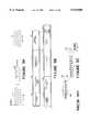
- FIG. 1is a pictorial representation of a TTY device
- FIG. 2is a block diagram representation of conventional architecture for TTY devices
- FIG. 3is a pictorial representation of the conventional dataflow for TTY devices
- FIG. 4is a block diagram representation of a telephone network
- FIGS. 5a 5b and 5care pictorial and block diagram representations of the transmission of caller identification in accordance with the prior art standards
- FIG. 6is a block diagram representation of the improved TTY device of the present invention.
- FIG. 7is a circuit diagram of a caller identification decoder circuit in accordance with the preferred embodiment of the present invention.
- FIG. 8is a flowchart representation of the operation of the controller in handling caller identification information.
- FIGS. 9, 10, and 11depict operation of the present invention to enable the "call back" function.
- FIG. 1is a pictorial representation of a TTY device 201.
- TTY device 201includes a keyboard 203 and a display 205. Additionally, acoustic coupling members 207, 209 are provided for acoustically coupling with a telephone handset. Additionally, TTY device 201 is equipped with a tape printer system 211 which allows for printing of the textual messages and/or telephone numbers originating from the TTY device 201 or received by the TTY device 201.
- FIG. 2is a schematic block diagram of the function of a typical TTY.
- the usertypes on a keyboard 12 to input characters into a microprocessor 14. Characters which are received or transmitted by the microprocessor 14 are received or transmitted by the microprocessor 14 and are also displayed to the user on a visual electronic display 16. Characters may also optionally be displayed by means of a hard copy printer 18.
- Microprocessor 14is largely responsible for the implementation of the various timing and decoding functions of the TTY.
- Microprocessor 14has data and address buses, jointly indicated at 20, which connect to a read-only memory (ROM) 22 and a random access memory (RAM) 24. Appropriate control lines 26 and 28 connect to the ROM 22 and RAM 24 so as to control the operation thereof.
- ROMread-only memory
- RAMrandom access memory
- ROM 22is intended to contain the program which dictates the functional operation of microprocessor 14.
- RAM 24is utilized as a holding place or stack for data coming into or out of the TTY.
- the microprocessor, the RAM and the ROMare all combined in a single integrated circuit, while in others they are separate circuits.
- microprocessor 14connects through analog circuitry 30 to one of three separate outputs.
- the analog circuitry 30is, most preferably, a modem.
- One output of the analog circuitry 30could be a telephone direct connect circuitry 32 which connects the modem directly by hardwiring into the telephone network.
- a second possible output from the analog circuitryis through an acoustic output 34 intended to audibly connect to the microphone of a telephone handset.
- An acoustic input circuitry 36is connected to a microphone, which is intended to audibly couple to the speaker in a telephone handset.
- the acoustic output speaker and the acoustic input microphonemay be connected through a so-called "acoustic coupler" to a conventional telephone handset. In any TTY, either the hardwired connection or the acoustic connection is provided, and sometimes both.
- FIG. 3Shown in FIG. 3 is a simplified schematic of how one implementation of the input and outputs of the analog circuitry would work.
- the audible input from a microphone or telephoneis translated into electronic components and then presented to an amplifier 42.
- the output of the amplifieris presented to two phase locked-loops 44.
- One of the phase locked-loops 44is tuned to a frequency of 1800 Hertz, while the other phase locked-loop 44 is tuned to a frequency of 1400 Hertz.
- 1800 Hertz and 1400 Hertzare the designated carrier frequencies for standard Baudot communication.
- output signalsare presented to a LPF (low pass filter) transmit wave shaping circuit 46.
- the output of that circuitryconsisting of alternate 1400 and 1800 Hertz signals, is presented to an amplifier 48 which is hardwired to the speaker or telephone line.
- the present inventionallows a conventional TTY device to receive, process, and display caller identification information to allow the hearing impaired user greater flexibility and control over his or her time by allowing him or her to determine the identity of a caller without having to take the telephone call at that time.
- the followingis a description of the standard caller identification information which is available at this time.
- FIG. 4provides a simplified block diagram of a telephone network 109, in accordance with the prior art, which will be utilized to describe some fundamentals of telephony which may be necessary to understand the present invention.
- telephone network 109can be utilized to allow calloriginator 111 to utilize telephone 113 to place a telephone call to call-receiver 115, which utilizes telephone 117 to receive such a call.
- Fairly elaborate switching networks 119 and 121connect call-originator 111 and call-originator 115 to central office 123 of telephone network 109.
- central office 123there is a source of electrical current, identified as talk battery 125, which is utilized to determine whether or not a particular telephone (i.e., telephone 113 or 115) is in the "on-hook" or "off-hook” condition. If the handset of a particular telephone is lifted from the cradle of the telephone, the telephone goes from an on-hook condition to an off-hook condition.
- dial tone generator 127 at central office 123 of telephone network 109is utilized to generate an audible dial tone which indicates to the telephone operator that an outgoing call may be initiated.
- call-originator 111may lift the handset from the cradle of telephone 113, and receive an audible dial tone through the operation of dial tone generator 127 and central office 123.
- call-originator 111dials the telephone number of call-receiver 115
- ring generator 129 at central office 123generators a plurality of ring signals which are sent through switching network 121 to telephone 117 to alert callreceiver 115 that a call is incoming.
- call-receiver 115lifts his or her handset off of the cradle of telephone 117, voice path 131 is established between call-originator 111 and call-receiver 115.
- caller-identification informationmay be transmitted automatically between call-originator 111 and call-receiver 115, through telephone network 109, in a manner which will be described below with reference to FIGS. 5a, 5b and 5c.
- the transmissionIn the United States of America, in accordance with the Bellcore Specification No. 220, the transmission must occur between the first and second rings.
- FIG. 5asuch caller-identification information signals transmitted to call-receiver 115 are depicted in simplified form, with caller-identification information 139 occurring between first ring 135 and second ring 137.
- the Bellcore Specificationrequires that caller-identification information 139 occur at least 500 milliseconds after first ring 135 ceases.
- the signal which represents the caller-identification informationwill begin transmission one-half of one second, or longer, after the termination of first ring 135.
- Caller-identification information 139is transmitted serially, utilizing a frequency-shift-keying technique, which is well known in the prior art.
- the Bellcore Specificationalso requires that the transmission of calleridentification information 139 end at least 427 milliseconds prior to the commencement of second ring 137. Typically, there is a four second interval between first ring 135 and second ring 137, so a significant amount of time is available for the communication of caller-identification information. Altogether, there is available a period of 2,570 milliseconds for the transmission of caller-identification information, not including pauses required by the Bellcore Specification (such pauses or periods of silence are required at the beginning and end of the message). At 1,200 baud, this message interval is sufficient to transmit 3,084 bits, or 308 bytes.
- the blocks of data which make up the caller-identification information 139is set forth in block diagram form in FIG. 5b.
- the first component of the caller-identification informationis a synchronization signal 141 which comprises a channel seizure signal having a duration of 250 milliseconds of frequencyshift-keying encoding of a bit pattern of alternating zeros and ones.
- a synchronization signalis utilized to provide a recognizable pattern to alert applicable caller-identification decoding equipment that caller-identification information follows.
- Pre-message pause 143follows synchronization signals 141, and has a duration of 150 milliseconds, plus or minus 25 milliseconds. The purpose of such a pre-message pause 143 is to condition the receiver for the data which follows.
- message-type identifier 145follows synchronization signals 141.
- Message type identifier 145is typically one byte of data which identifies the type of caller-identification message which is being sent.
- 04 hexadecimalidentifies a single message caller-identification message
- 80 hexadecimalidentifies a caller-identification message which includes both a telephone number and a name.
- message byte count 147provides an indication of the total length of the caller-identification information. This is important because the directory name associated with the source telephone number will have a different length for each particular name.
- sub-message type 149identifies the type of submessage which is transmitted with the caller-identification information.
- Sub-message link 151identifies the length of the sub-message which follows.
- Message 153consists of information which is described in more detail below with respect to FIG. 5c.
- Message 153is followed by checksum byte 155 which, in accordance with the prior art techniques, provides a checksum total to ensure that data received has not been lost or altered in any way during the transmission.
- the receiving unit of a caller-identification decodergenerates a checksum in response to the entire caller-identification bit stream, and thereafter compares this checksum with checksum byte 155.
- checksumsmatch, then no bits were lost in the transmission; however, if the checksum generated by the caller-identification decoder does not match checksum byte 155 received at the decoder, then one or more data bits may have been lost in the transmission, and the information may be unreliable or unusable.
- the final component of a caller-identification messageis post-message pause 157, which is a quiescent period prior to second ring 137.
- the first eight bits of the messageinclude month bits "MM", day bits “DD”, hour bits “HH”, and minute bits "MM”. These eight bits provide the month and date, along with the hour and minute, in military time, of the telephone call. Note that no information is provided regarding the year.
- the next portion of message 153is either (1) a ten digit telephone number, or (2) a single digit which identifies that caller-identification information is either (a) not available, or (b) has been blocked to maintain the caller's privacy.
- caller-identification informationwhich identifies the name associated with the particular preceding telephone number. If this information is unavailable, a single character "O" is provided. If this information is blocked for reasons of privacy, a single character "P” is provided. However, if this information is both available and not blocked, a multi-bit string follows which sets forth a name associated with the particular preceding telephone number (for example, "John Doe").
- caller-identification informationmay be solely data which identifies a telephone number associated with the telephone unit utilized to place a call, or the telephone number associated with the telephone unit utilized to place the call in combination with alphabetic characters identifying a name associated with that particular number in a telephone directory (i.e., a telephone director data base). In either event, whether the directory name is provided or not, this information can be considered to be the "caller-identification information.”
- the particular details of the caller-identification standards in the United States of Americaare set forth in the publications of the Bell Communications Research Laboratories, which are identified as "Bellcore", and include (1) Technical Reference No. TR-TSY-00032, issued Nov.
- FIG. 6is a block diagram representation of the implementation of the TTY device with caller identification function of the present invention.
- a microprocessor 301is provided for processing program instructions, and for handling data, including the caller identification information data.
- a controller 301communicates with the other components of the TTY device of the present invention through address bus 313, data bus 315, and control bus 317.
- a reprogrammable read only memory (ROM) 303is provided for storing the program instructions.
- a random access memory (RAM) 305is provided for storing data, including caller identification information.
- a printer controller 307is provided for controlling the operation of printer 309.
- a liquid crystal display(with 40 characters on two lines) is also provided for displaying textual information, including the caller identification information, in accordance with the present invention.
- the improved TTY device of the present inventionincludes a modem 325 which is connected through buffer 319 to the address bus 313, the data bus 315, and the control bus 317.
- Keyboard 323is connected to data bus 315 and control bus 317 and allows the operator to generate textual messages.
- a voice and DTMF generator 327is connected through buffer 321 to the address bus 313, data bus 315, and control bus 317.
- a microphone and audio amplifier section 335is also provided. The microphone and audio amplifier section 335, the modem 325, and the voice and DTMF generator 327 are coupled to circuitry including a phase log loop and analog switches identified as block 329.
- a telephone line interface 333is provided in the improved TTY for receiving the TIP signal and the RING signal from the telephone line through a conventional RJ-11 connection, for processing the TIP and RING signals, and for passing the processed TIP and RING signals to the caller identification decoder 331.
- the caller identification decoder 331is coupled to data bus 315 and control bus 317.
- caller identification decoder 331passes the decoded caller identification information (preferably in ASCII form) through data bus 315 and control bus 317 to controller 301 where the ASCII characters are further processed and displayed on liquid crystal display 311, and stored in memory at RAM 305.
- FIG. 7is an electrical schematic drawing of the caller identification interface 333 and caller identification decoder 331.
- FIG. 7is an electrical schematic depiction of the telephone line interface 333 and caller identification decoder 331 of FIG. 6.
- the telephone line interface 333includes a number of circuit components which are utilized to receive and process the TIP and RING signals which are received from the telephone line.
- the isolation capacitors C212, C213, C214, C215are utilized to block the DC component which is present in the TIP and RING signals.
- Diode bridge 351is provided to rectify the alternating current and produce a direct current output.
- the direct current output of the diode bridge 351is supplied to pins 3 and 4 of caller identification decoder 331.
- the amplitude of the signalis reduced through the voltage divider provided by resistors R23, R239, and R240.
- the TIP signalis applied to pin 1 of caller identification decoder 331 through resistor R237 which reduces the amplitude of the TIP signal.
- the RING signalis supplied to pin 2 of caller identification decoder 331 through resistor R241 which likewise reduces the amplitude of the voltage supplied to the caller identification decoder 331.
- the ringing signal RINGis supplied to pin 2 of the caller identification decoder 331.
- the detection of the first ringwill initiate action of the caller identification decoder 331.
- the caller identification informationis carried on the TIP signal in accordance with FSK modulation.
- the signalis rectified by diode bridge 351 and supplied to pins 3 and 4 of caller identification decoder 331.
- output pin 12(RINGDET) goes low to signal to the controller that a call has been received.
- caller identification decoder 331operates to decode the caller identification information.
- output pin 13goes low to indicate that the carrier signal has been detected.
- output pin 14provides a serial, ASCII character string which is representative of the caller identification information.
- the microprocessormonitors RINGDET, CALIDCO, and CALIDO via the data buses in order to determine the initiation of a call, the detection of the carrier signal, and the serial ASCII characters which are representation of the caller identification information.
- FIG. 8is a flow chart representation of the operation of controller 301 (of FIG. 6) in processing and displaying the caller identification information.
- the processingbegins at software block 501, and continues at software block 503, wherein controller 301 monitors the data bus to determine whether the RINGDET signal has been detected. Once the RINGDET signal has been detected, control passes to software block 505, wherein controller 301 monitors for the start bit which indicates the commencement of a string of data representative of the caller identification information. Once the start bit is detected, in accordance with software block 507, control passes to software block 509, wherein controller 301 is utilized to record the ASCII characters which are present on the data bus. Next, in accordance with software block 511, controller 301 is utilized to monitor and detect the stop bit. Once the stop bit is detected, control passes to software blocks 513 and 515, wherein controller 301 is utilized to convert the serial ASCII data into parallel data, and push the parallel data to the LCD display on the data bus. The process terminates at software block 517.
- the present inventionis utilized to provide the caller identification to the user.
- the present inventionwill generate a listing of calls which have been previously received but not answered.
- the operatormay return to his or her TTY device and scroll through a listing of the calls which have been received but not answered.
- the LCD display 311(of FIG. 6) is utilized to display the area code, phone number, date, and time, and name of the calling party.
- the present inventionis equipped with a "call back" feature which allows the operator to scroll through his or her listing of calls received, and to automatically initiate a call back to the call originating party. This process is depicted in broad overview in flow chart form in FIG. 9. The process begins at software block 519, and continues to software block 521, wherein controller 301 determines whether the call back function has been selected.
- depression of the "ENTER" keyis utilized by the operator to select the "call back" function.
- controlpasses to software block 523, wherein the controller 301 is utilized to examine the content of the display.
- controller 301is utilized to locate the phone number field in the display.
- controller 301is utilized to determine whether the call is a local or long distance call. If the call is a long distance call, control passes to software block 529, wherein controller 301 is utilized to set up for long distance dialing.
- controller 301is utilized to actuate a DTMF generator located within the TTY device which initiates the DTMF tones which dial the number selected through the "call back" function. Finally, the process ends at software block 533.
- the "call back" functionis very advantageous for the hearing impaired since it allows the use of the caller identification information which is transmitted through the telephone system to be recorded, preserved, and reviewed in order to serve a function similar to that of a telephone answering machine (TAD) which is a common function provided in many consumer products for persons which are not hearing impaired.
- TADtelephone answering machine
- a hearing impaired personmay find a TAD of little or no utility. Consequently, the ability of the present invention to record in memory a plurality of previously received, but not answered, calls allows the hearing impaired individual to obtain some of the advantages available in commercial products which are presently enjoyed by the non hearing impaired individuals through use of the recordation of voices.
- the "call back" functionalso presents another advantage which is useful for both the hearing impaired and those that are not hearing impaired.
- the call back functioncan be utilized to record all calls received until a predetermined amount of memory is utilized.
- the TTY present inventionutilizes a stack memory which pushes the new call to the top of the stack while deleting old calls from the bottom of the stack.
- the size of the memorymay determine the total number of calls which are recorded.
- the memory stack associated with the "call back" functioncan be utilized to allow one to provide a business record of daily or hourly activities. In accordance with the present invention, this data may be reviewed in the LCD display, or printed on the paper tape utilizing the dedicated printer of the TTY device.
- FIGS. 10 and 11will now be utilized to further describe the "call back" function which is depictive in flow chart form in FIG. 9.
- a databaseis provided which includes a number of fields for recordation of information relating to calls received by the telecommunication device. The following fields are provided: a time of day (TOD) field, a date field, a number field, and a name field. Caller identification information from calls received by the TTY device are recorded. The information can be reviewed by the operator, as is now described with reference to FIG. 11. The content of the database may be scrolled utilizing dedicated function keys, such as the uparrow key 601 and the down-arrow key 603.
- the particular telephone number to be utilized in the call back functionmay be selected by depression of a dedicated key, such as the "Enter" key 605. This will cause the microprocessor to locate the telephone number, determine whether it is a local or long distance call, and initiate actuation of the DTMF actuator carried within the TTY device in order to initiate telephone communication.
- a dedicated keysuch as the "Enter” key 605.
Landscapes
- Engineering & Computer Science (AREA)
- Signal Processing (AREA)
- Computer Networks & Wireless Communication (AREA)
- Telephone Function (AREA)
Abstract
Description
Claims (15)
Priority Applications (1)
| Application Number | Priority Date | Filing Date | Title |
|---|---|---|---|
| US08/885,303US5915000A (en) | 1997-06-30 | 1997-06-30 | Text teletype writer with caller identification function |
Applications Claiming Priority (1)
| Application Number | Priority Date | Filing Date | Title |
|---|---|---|---|
| US08/885,303US5915000A (en) | 1997-06-30 | 1997-06-30 | Text teletype writer with caller identification function |
Publications (1)
| Publication Number | Publication Date |
|---|---|
| US5915000Atrue US5915000A (en) | 1999-06-22 |
Family
ID=25386603
Family Applications (1)
| Application Number | Title | Priority Date | Filing Date |
|---|---|---|---|
| US08/885,303Expired - Fee RelatedUS5915000A (en) | 1997-06-30 | 1997-06-30 | Text teletype writer with caller identification function |
Country Status (1)
| Country | Link |
|---|---|
| US (1) | US5915000A (en) |
Cited By (38)
| Publication number | Priority date | Publication date | Assignee | Title |
|---|---|---|---|---|
| US6212265B1 (en)* | 1998-01-27 | 2001-04-03 | Darin Duphorne | Method and apparatus for electronic mail notification |
| US20020196914A1 (en)* | 2001-06-25 | 2002-12-26 | Bellsouth Intellectual Property Corporation | Audio caller identification |
| US6535594B1 (en)* | 2001-11-15 | 2003-03-18 | Bettie Reeves-Nobles | Printing caller ID |
| US6560317B1 (en)* | 2002-01-03 | 2003-05-06 | Intel Corporation | Receiving caller identification information with a telecommunications device for the deaf |
| US6721399B2 (en) | 2000-12-15 | 2004-04-13 | Siemens Information & Communication Networks, Inc. | Apparatus and systems for utilizing caller ID data to automate return call processing |
| US20050147228A1 (en)* | 2003-12-24 | 2005-07-07 | Perrella Ronald J. | Client survey systems and methods using caller identification information |
| US20050152525A1 (en)* | 2004-01-12 | 2005-07-14 | Kent Larry G.Jr. | Intelligent remote caller ID |
| US7079837B1 (en) | 2001-11-06 | 2006-07-18 | Bellsouth Intellectual Property Corporation | Caller identification queue for wireless telephones |
| US7085358B2 (en) | 2001-06-25 | 2006-08-01 | Bellsouth Intellectual Property Corporation | Visual caller identification |
| EP1689160A1 (en)* | 2005-02-04 | 2006-08-09 | Sap Ag | Data transmission over a telephone connection |
| US7127488B1 (en) | 2002-07-23 | 2006-10-24 | Bellsouth Intellectual Property Corp. | System and method for gathering information related to a geographical location of a caller in an internet-based communication system |
| US7139374B1 (en) | 2002-07-23 | 2006-11-21 | Bellsouth Intellectual Property Corp. | System and method for gathering information related to a geographical location of a callee in a public switched telephone network |
| US20070127643A1 (en)* | 2002-12-17 | 2007-06-07 | Cisco Technology, Inc. | System and Method for Communicating Text Teletype (TTY) Information in a Communication Network |
| US7254226B1 (en) | 2001-05-08 | 2007-08-07 | At&T Intellectual Property, Inc. | Call waiting priority alert |
| US7269249B2 (en) | 2001-09-28 | 2007-09-11 | At&T Bls Intellectual Property, Inc. | Systems and methods for providing user profile information in conjunction with an enhanced caller information system |
| US7269412B2 (en) | 2003-05-29 | 2007-09-11 | At&T Bls Intellectual Property, Inc. | Caller identification device and method of operation thereof |
| US7280646B2 (en) | 2003-04-18 | 2007-10-09 | At&T Bls Intellectual Property, Inc. | Dynamic Caller ID messaging |
| US7283625B2 (en) | 2003-04-18 | 2007-10-16 | At&T Bls Intellectual Property, Inc. | Caller ID messaging telecommunications services |
| US7315618B1 (en) | 2001-12-27 | 2008-01-01 | At&T Bls Intellectual Property, Inc. | Voice caller ID |
| US7315614B2 (en) | 2001-08-14 | 2008-01-01 | At&T Delaware Intellectual Property, Inc. | Remote notification of communications |
| US7385992B1 (en) | 2002-05-13 | 2008-06-10 | At&T Delaware Intellectual Property, Inc. | Internet caller-ID integration |
| US7388949B2 (en) | 2000-12-28 | 2008-06-17 | At&T Delaware Intellectual Property, Inc. | System and method for audio caller identification service |
| US7391857B2 (en)* | 2000-12-15 | 2008-06-24 | Siemens Communications, Inc. | Methods and apparatus for forwarding caller ID data from a call answering device utilizing a call control system |
| US7403768B2 (en) | 2001-08-14 | 2008-07-22 | At&T Delaware Intellectual Property, Inc. | Method for using AIN to deliver caller ID to text/alpha-numeric pagers as well as other wireless devices, for calls delivered to wireless network |
| US7443964B2 (en) | 2003-04-18 | 2008-10-28 | At&T Intellectual Property, I,L.P. | Caller ID messaging |
| US7463727B2 (en) | 2003-04-18 | 2008-12-09 | At&T International Property, I, L.P. | Caller ID messaging device |
| EP2096848A1 (en)* | 2008-02-29 | 2009-09-02 | Research In Motion Limited | System and method for differentiating between incoming and outgoing messages and identifying correspondents in a TTY communication |
| US20090221321A1 (en)* | 2008-02-29 | 2009-09-03 | Research In Motion Limited | System and method for differentiating between incoming and outgoing messages and identifying correspondents in a tty communication |
| US7586898B1 (en) | 2002-05-13 | 2009-09-08 | At&T Intellectual Property, I, L.P. | Third party content for internet caller-ID messages |
| US7609832B2 (en) | 2003-11-06 | 2009-10-27 | At&T Intellectual Property, I,L.P. | Real-time client survey systems and methods |
| US7623645B1 (en) | 2002-07-23 | 2009-11-24 | At&T Intellectual Property, I, L.P. | System and method for gathering information related to a geographical location of a caller in a public switched telephone network |
| US7623849B2 (en) | 2003-11-13 | 2009-11-24 | At&T Intellectual Property, I, L.P. | Method, system, and storage medium for providing comprehensive originator identification services |
| US20090323905A1 (en)* | 2008-02-29 | 2009-12-31 | Research In Motion Limited | System and method for differentiating between incoming and outgoing messages and identifying correspondents in a tty communication |
| US7792143B1 (en) | 2005-03-25 | 2010-09-07 | Cisco Technology, Inc. | Method and apparatus for interworking dissimilar text phone protocols over a packet switched network |
| US7978833B2 (en) | 2003-04-18 | 2011-07-12 | At&T Intellectual Property I, L.P. | Private caller ID messaging |
| US8160226B2 (en) | 2007-08-22 | 2012-04-17 | At&T Intellectual Property I, L.P. | Key word programmable caller ID |
| US8195136B2 (en) | 2004-07-15 | 2012-06-05 | At&T Intellectual Property I, L.P. | Methods of providing caller identification information and related registries and radiotelephone networks |
| US8243909B2 (en) | 2007-08-22 | 2012-08-14 | At&T Intellectual Property I, L.P. | Programmable caller ID |
Citations (8)
| Publication number | Priority date | Publication date | Assignee | Title |
|---|---|---|---|---|
| US5228073A (en)* | 1991-07-22 | 1993-07-13 | Smith Frederick D | Call identification display system |
| US5303301A (en)* | 1991-05-22 | 1994-04-12 | Matsushita Electric Industrial Co., Ltd. | Telephone apparatus with call-back indication |
| US5325417A (en)* | 1992-05-20 | 1994-06-28 | Ultratec, Inc. | Telecommunication device for the deaf with automatic self-identification |
| US5467385A (en)* | 1994-01-27 | 1995-11-14 | Reuben; Douglas S. | Calling number display and recording system |
| US5524140A (en)* | 1992-03-31 | 1996-06-04 | Visual Access Technologies, Inc. | Telephone answering device linking displayed data with recorded audio message |
| US5546447A (en)* | 1994-06-29 | 1996-08-13 | Intel Corporation | Displaying caller identification information in a computer system |
| US5604786A (en)* | 1994-06-10 | 1997-02-18 | Ultratec, Inc. | Telephone with unified features for hearing and deaf users |
| US5699417A (en)* | 1995-04-21 | 1997-12-16 | Cidco Incorporated | Text transmission using DTMF signalling |
- 1997
- 1997-06-30USUS08/885,303patent/US5915000A/ennot_activeExpired - Fee Related
Patent Citations (8)
| Publication number | Priority date | Publication date | Assignee | Title |
|---|---|---|---|---|
| US5303301A (en)* | 1991-05-22 | 1994-04-12 | Matsushita Electric Industrial Co., Ltd. | Telephone apparatus with call-back indication |
| US5228073A (en)* | 1991-07-22 | 1993-07-13 | Smith Frederick D | Call identification display system |
| US5524140A (en)* | 1992-03-31 | 1996-06-04 | Visual Access Technologies, Inc. | Telephone answering device linking displayed data with recorded audio message |
| US5325417A (en)* | 1992-05-20 | 1994-06-28 | Ultratec, Inc. | Telecommunication device for the deaf with automatic self-identification |
| US5467385A (en)* | 1994-01-27 | 1995-11-14 | Reuben; Douglas S. | Calling number display and recording system |
| US5604786A (en)* | 1994-06-10 | 1997-02-18 | Ultratec, Inc. | Telephone with unified features for hearing and deaf users |
| US5546447A (en)* | 1994-06-29 | 1996-08-13 | Intel Corporation | Displaying caller identification information in a computer system |
| US5699417A (en)* | 1995-04-21 | 1997-12-16 | Cidco Incorporated | Text transmission using DTMF signalling |
Cited By (68)
| Publication number | Priority date | Publication date | Assignee | Title |
|---|---|---|---|---|
| US6212265B1 (en)* | 1998-01-27 | 2001-04-03 | Darin Duphorne | Method and apparatus for electronic mail notification |
| US7391857B2 (en)* | 2000-12-15 | 2008-06-24 | Siemens Communications, Inc. | Methods and apparatus for forwarding caller ID data from a call answering device utilizing a call control system |
| US7634075B2 (en) | 2000-12-15 | 2009-12-15 | Siemens Communications, Inc. | Apparatus and systems for utilizing caller ID data to automate return call processing |
| US6721399B2 (en) | 2000-12-15 | 2004-04-13 | Siemens Information & Communication Networks, Inc. | Apparatus and systems for utilizing caller ID data to automate return call processing |
| US20040146146A1 (en)* | 2000-12-15 | 2004-07-29 | Siemens Information And Communication Networks, Inc. | Apparatus and systems for utilizing caller ID data to automate return call processing |
| US7388949B2 (en) | 2000-12-28 | 2008-06-17 | At&T Delaware Intellectual Property, Inc. | System and method for audio caller identification service |
| US7254226B1 (en) | 2001-05-08 | 2007-08-07 | At&T Intellectual Property, Inc. | Call waiting priority alert |
| US7085358B2 (en) | 2001-06-25 | 2006-08-01 | Bellsouth Intellectual Property Corporation | Visual caller identification |
| US7012999B2 (en) | 2001-06-25 | 2006-03-14 | Bellsouth Intellectual Property Corporation | Audio caller identification |
| US20060072719A1 (en)* | 2001-06-25 | 2006-04-06 | Bellsouth Intellectual Property Corporation | Audio caller identification |
| US7463724B2 (en) | 2001-06-25 | 2008-12-09 | At&T Intellectual Property, I.L.P. | Audio caller identification |
| US7295656B2 (en) | 2001-06-25 | 2007-11-13 | At&T Bls Intellectual Property, Inc. | Audio caller identification |
| US7929675B2 (en) | 2001-06-25 | 2011-04-19 | At&T Intellectual Property I, L.P. | Visual caller identification |
| US20020196914A1 (en)* | 2001-06-25 | 2002-12-26 | Bellsouth Intellectual Property Corporation | Audio caller identification |
| US8019064B2 (en) | 2001-08-14 | 2011-09-13 | At&T Intellectual Property I, L.P. | Remote notification of communications |
| US7315614B2 (en) | 2001-08-14 | 2008-01-01 | At&T Delaware Intellectual Property, Inc. | Remote notification of communications |
| US7403768B2 (en) | 2001-08-14 | 2008-07-22 | At&T Delaware Intellectual Property, Inc. | Method for using AIN to deliver caller ID to text/alpha-numeric pagers as well as other wireless devices, for calls delivered to wireless network |
| US8155287B2 (en) | 2001-09-28 | 2012-04-10 | At&T Intellectual Property I, L.P. | Systems and methods for providing user profile information in conjunction with an enhanced caller information system |
| US7269249B2 (en) | 2001-09-28 | 2007-09-11 | At&T Bls Intellectual Property, Inc. | Systems and methods for providing user profile information in conjunction with an enhanced caller information system |
| US7634256B2 (en) | 2001-11-06 | 2009-12-15 | At&T Intellectual Property, I, L.P. | Caller identification queue for wireless telephones |
| US20070072596A1 (en)* | 2001-11-06 | 2007-03-29 | Bellsouth Intellectual Property Corporation | Caller identification queue for wireless telephones |
| US7079837B1 (en) | 2001-11-06 | 2006-07-18 | Bellsouth Intellectual Property Corporation | Caller identification queue for wireless telephones |
| US6535594B1 (en)* | 2001-11-15 | 2003-03-18 | Bettie Reeves-Nobles | Printing caller ID |
| US7418096B2 (en) | 2001-12-27 | 2008-08-26 | At&T Intellectual Property I, L.P. | Voice caller ID |
| US8139758B2 (en) | 2001-12-27 | 2012-03-20 | At&T Intellectual Property I, L.P. | Voice caller ID |
| US7315618B1 (en) | 2001-12-27 | 2008-01-01 | At&T Bls Intellectual Property, Inc. | Voice caller ID |
| US6560317B1 (en)* | 2002-01-03 | 2003-05-06 | Intel Corporation | Receiving caller identification information with a telecommunications device for the deaf |
| US7385992B1 (en) | 2002-05-13 | 2008-06-10 | At&T Delaware Intellectual Property, Inc. | Internet caller-ID integration |
| US7586898B1 (en) | 2002-05-13 | 2009-09-08 | At&T Intellectual Property, I, L.P. | Third party content for internet caller-ID messages |
| US7978841B2 (en) | 2002-07-23 | 2011-07-12 | At&T Intellectual Property I, L.P. | System and method for gathering information related to a geographical location of a caller in a public switched telephone network |
| US7139374B1 (en) | 2002-07-23 | 2006-11-21 | Bellsouth Intellectual Property Corp. | System and method for gathering information related to a geographical location of a callee in a public switched telephone network |
| US7127488B1 (en) | 2002-07-23 | 2006-10-24 | Bellsouth Intellectual Property Corp. | System and method for gathering information related to a geographical location of a caller in an internet-based communication system |
| US8452268B2 (en) | 2002-07-23 | 2013-05-28 | At&T Intellectual Property I, L.P. | System and method for gathering information related to a geographical location of a callee in a public switched telephone network |
| US9532175B2 (en) | 2002-07-23 | 2016-12-27 | At&T Intellectual Property I, L.P. | System and method for gathering information related to a geographical location of a callee in a public switched telephone network |
| US7623645B1 (en) | 2002-07-23 | 2009-11-24 | At&T Intellectual Property, I, L.P. | System and method for gathering information related to a geographical location of a caller in a public switched telephone network |
| US7817783B2 (en)* | 2002-12-17 | 2010-10-19 | Cisco Technology, Inc. | System and method for communicating text teletype (TTY) information in a communication network |
| US20070127643A1 (en)* | 2002-12-17 | 2007-06-07 | Cisco Technology, Inc. | System and Method for Communicating Text Teletype (TTY) Information in a Communication Network |
| US7463727B2 (en) | 2003-04-18 | 2008-12-09 | At&T International Property, I, L.P. | Caller ID messaging device |
| US7280646B2 (en) | 2003-04-18 | 2007-10-09 | At&T Bls Intellectual Property, Inc. | Dynamic Caller ID messaging |
| US8073121B2 (en) | 2003-04-18 | 2011-12-06 | At&T Intellectual Property I, L.P. | Caller ID messaging |
| US7564960B2 (en) | 2003-04-18 | 2009-07-21 | At&T Intellectual Property, I, L.P. | Methods, systems and computer program products for dynamic caller ID messaging |
| US7443964B2 (en) | 2003-04-18 | 2008-10-28 | At&T Intellectual Property, I,L.P. | Caller ID messaging |
| US7978833B2 (en) | 2003-04-18 | 2011-07-12 | At&T Intellectual Property I, L.P. | Private caller ID messaging |
| US7283625B2 (en) | 2003-04-18 | 2007-10-16 | At&T Bls Intellectual Property, Inc. | Caller ID messaging telecommunications services |
| US7269412B2 (en) | 2003-05-29 | 2007-09-11 | At&T Bls Intellectual Property, Inc. | Caller identification device and method of operation thereof |
| US7609832B2 (en) | 2003-11-06 | 2009-10-27 | At&T Intellectual Property, I,L.P. | Real-time client survey systems and methods |
| US7623849B2 (en) | 2003-11-13 | 2009-11-24 | At&T Intellectual Property, I, L.P. | Method, system, and storage medium for providing comprehensive originator identification services |
| US7945253B2 (en) | 2003-11-13 | 2011-05-17 | At&T Intellectual Property I, L.P. | Method, system, and storage medium for providing comprehensive originator identification services |
| US7672444B2 (en) | 2003-12-24 | 2010-03-02 | At&T Intellectual Property, I, L.P. | Client survey systems and methods using caller identification information |
| US8102994B2 (en) | 2003-12-24 | 2012-01-24 | At&T Intellectual Property I, L.P. | Client survey systems and methods using caller identification information |
| US20050147228A1 (en)* | 2003-12-24 | 2005-07-07 | Perrella Ronald J. | Client survey systems and methods using caller identification information |
| US6970546B2 (en) | 2004-01-12 | 2005-11-29 | Bellsouth Intellecutal Property Corp. | Intelligent remote caller ID |
| US20050152525A1 (en)* | 2004-01-12 | 2005-07-14 | Kent Larry G.Jr. | Intelligent remote caller ID |
| US8195136B2 (en) | 2004-07-15 | 2012-06-05 | At&T Intellectual Property I, L.P. | Methods of providing caller identification information and related registries and radiotelephone networks |
| EP1689160A1 (en)* | 2005-02-04 | 2006-08-09 | Sap Ag | Data transmission over a telephone connection |
| US20060178115A1 (en)* | 2005-02-04 | 2006-08-10 | Sap Aktiengesellschaft | Data transmission over an in-use transmission medium |
| US7995722B2 (en) | 2005-02-04 | 2011-08-09 | Sap Ag | Data transmission over an in-use transmission medium |
| US7792143B1 (en) | 2005-03-25 | 2010-09-07 | Cisco Technology, Inc. | Method and apparatus for interworking dissimilar text phone protocols over a packet switched network |
| US8416938B2 (en) | 2007-08-22 | 2013-04-09 | At&T Intellectual Property I, L.P. | Programmable caller ID |
| US8787549B2 (en) | 2007-08-22 | 2014-07-22 | At&T Intellectual Property I, L.P. | Programmable caller ID |
| US8160226B2 (en) | 2007-08-22 | 2012-04-17 | At&T Intellectual Property I, L.P. | Key word programmable caller ID |
| US8243909B2 (en) | 2007-08-22 | 2012-08-14 | At&T Intellectual Property I, L.P. | Programmable caller ID |
| US8135376B2 (en) | 2008-02-29 | 2012-03-13 | Research In Motion Limited | System and method for differentiating between incoming and outgoing messages and identifying correspondents in a TTY communication |
| US8190183B2 (en) | 2008-02-29 | 2012-05-29 | Research In Motion Limited | System and method for differentiating between incoming and outgoing messages and identifying correspondents in a TTY communication |
| EP2096848A1 (en)* | 2008-02-29 | 2009-09-02 | Research In Motion Limited | System and method for differentiating between incoming and outgoing messages and identifying correspondents in a TTY communication |
| US20090323905A1 (en)* | 2008-02-29 | 2009-12-31 | Research In Motion Limited | System and method for differentiating between incoming and outgoing messages and identifying correspondents in a tty communication |
| US20090221321A1 (en)* | 2008-02-29 | 2009-09-03 | Research In Motion Limited | System and method for differentiating between incoming and outgoing messages and identifying correspondents in a tty communication |
| US7957717B2 (en) | 2008-02-29 | 2011-06-07 | Research In Motion Limited | System and method for differentiating between incoming and outgoing messages and identifying correspondents in a TTY communication |
Similar Documents
| Publication | Publication Date | Title |
|---|---|---|
| US5915000A (en) | Text teletype writer with caller identification function | |
| US6038443A (en) | Calling party announcement apparatus | |
| US6072859A (en) | Apparatus and method of generating voice message of caller's number in case of incoming call in telephone | |
| US7305076B1 (en) | Method and apparatus for improved paging receiver and system | |
| US7454000B1 (en) | Method and apparatus for improved personal communication devices and systems | |
| US5263084A (en) | Spontaneous caller identification with call-waiting | |
| KR100308348B1 (en) | Ring count controlled by incoming call related information | |
| JPH0652914B2 (en) | Caller telephone number display | |
| JPH01152847A (en) | Terminal equipment for caller number notifying communication network | |
| JP3341850B2 (en) | Incoming terminal | |
| EP0957622A2 (en) | apparatus and method for selecting an outgoing greeting message based on call related information | |
| JP3667800B2 (en) | Telephone equipment | |
| JPS62263757A (en) | Data communication equipment | |
| JP2656293B2 (en) | Caller identification communication device | |
| JPS61274460A (en) | Telephone set | |
| JPH0239661A (en) | Communications system | |
| JPH09200317A (en) | Communication device | |
| JPS62263744A (en) | Data communication equipment | |
| JPH07212831A (en) | Cordless telephone terminal and its operation | |
| JPS62263749A (en) | Data communication equipment | |
| JPH01258533A (en) | Telephone system with incoming information display function | |
| JPS6047539A (en) | Telephone calling system | |
| JPH08289034A (en) | Information communication system | |
| JPH05336240A (en) | Caller name notification method using portable storage device | |
| JPH04369958A (en) | Facsimile equipment for transmission notification |
Legal Events
| Date | Code | Title | Description |
|---|---|---|---|
| AS | Assignment | Owner name:MESSAGETEXT LICENSING INCORPORATED, TEXAS Free format text:ASSIGNMENT OF ASSIGNORS INTEREST;ASSIGNOR:KROWN MANUFACTURING, INC.;REEL/FRAME:013403/0654 Effective date:20020930 | |
| REMI | Maintenance fee reminder mailed | ||
| FPAY | Fee payment | Year of fee payment:4 | |
| SULP | Surcharge for late payment | ||
| AS | Assignment | Owner name:KROWN MANUFACTURING/COMPU TTY. INC., TEXAS Free format text:ASSIGNMENT OF ASSIGNORS INTEREST;ASSIGNORS:NGUYEN, VINH H.;ANDER, SIDNEY;DAVIS, BRYAN H.;AND OTHERS;REEL/FRAME:014351/0133;SIGNING DATES FROM 20030728 TO 20030730 | |
| AS | Assignment | Owner name:KROWN MANUFACTURING/COMPUTTY, INC., TEXAS Free format text:ASSIGNMENT OF ASSIGNORS INTEREST;ASSIGNORS:NGUYEN, VINH H.;ANDER, SIDNEY;DAVIS, BRYAN H.;AND OTHERS;REEL/FRAME:014438/0526 Effective date:19990622 | |
| REMI | Maintenance fee reminder mailed | ||
| LAPS | Lapse for failure to pay maintenance fees | ||
| STCH | Information on status: patent discontinuation | Free format text:PATENT EXPIRED DUE TO NONPAYMENT OF MAINTENANCE FEES UNDER 37 CFR 1.362 | |
| FP | Expired due to failure to pay maintenance fee | Effective date:20070622 |