US5913816A - Intubation device and method - Google Patents
Intubation device and methodDownload PDFInfo
- Publication number
- US5913816A US5913816AUS08/963,593US96359397AUS5913816AUS 5913816 AUS5913816 AUS 5913816AUS 96359397 AUS96359397 AUS 96359397AUS 5913816 AUS5913816 AUS 5913816A
- Authority
- US
- United States
- Prior art keywords
- conduit
- handle
- distal end
- imaging
- image
- Prior art date
- Legal status (The legal status is an assumption and is not a legal conclusion. Google has not performed a legal analysis and makes no representation as to the accuracy of the status listed.)
- Expired - Fee Related
Links
- 238000002627tracheal intubationMethods0.000titleclaimsabstractdescription50
- 238000000034methodMethods0.000titleclaimsdescription29
- 238000003384imaging methodMethods0.000claimsabstractdescription93
- 238000011010flushing procedureMethods0.000claimsabstractdescription46
- 238000005286illuminationMethods0.000claimsabstractdescription35
- 239000000463materialSubstances0.000claimsdescription13
- 239000004033plasticSubstances0.000claimsdescription8
- 239000002184metalSubstances0.000claimsdescription4
- 229910052751metalInorganic materials0.000claimsdescription4
- 230000003287optical effectEffects0.000claimsdescription3
- 239000013307optical fiberSubstances0.000claimsdescription3
- 239000012780transparent materialSubstances0.000claimsdescription3
- 229910052594sapphireInorganic materials0.000claimsdescription2
- 239000010980sapphireSubstances0.000claimsdescription2
- 239000002991molded plasticSubstances0.000claims2
- 239000007789gasSubstances0.000abstractdescription14
- 239000012530fluidSubstances0.000abstractdescription13
- 230000001954sterilising effectEffects0.000abstractdescription2
- 238000004659sterilization and disinfectionMethods0.000abstractdescription2
- 210000003813thumbAnatomy0.000description15
- 210000003437tracheaAnatomy0.000description10
- 238000013461designMethods0.000description8
- 239000000835fiberSubstances0.000description6
- 230000000694effectsEffects0.000description4
- 238000003780insertionMethods0.000description4
- 230000037431insertionEffects0.000description4
- 238000012800visualizationMethods0.000description4
- 230000009471actionEffects0.000description3
- 239000008280bloodSubstances0.000description3
- 210000004369bloodAnatomy0.000description3
- 238000003825pressingMethods0.000description3
- 238000007794visualization techniqueMethods0.000description3
- 230000001154acute effectEffects0.000description2
- 239000000853adhesiveSubstances0.000description2
- 230000001070adhesive effectEffects0.000description2
- 230000008901benefitEffects0.000description2
- 230000003247decreasing effectEffects0.000description2
- 230000000881depressing effectEffects0.000description2
- 238000009826distributionMethods0.000description2
- 238000001125extrusionMethods0.000description2
- 238000003754machiningMethods0.000description2
- 230000007246mechanismEffects0.000description2
- 238000000465mouldingMethods0.000description2
- 210000003097mucusAnatomy0.000description2
- 239000007787solidSubstances0.000description2
- 206010000060Abdominal distensionDiseases0.000description1
- 206010028980NeoplasmDiseases0.000description1
- 230000005856abnormalityEffects0.000description1
- 230000003444anaesthetic effectEffects0.000description1
- QVGXLLKOCUKJST-UHFFFAOYSA-Natomic oxygenChemical compound[O]QVGXLLKOCUKJST-UHFFFAOYSA-N0.000description1
- 238000005452bendingMethods0.000description1
- 230000009286beneficial effectEffects0.000description1
- 230000005540biological transmissionEffects0.000description1
- 238000010276constructionMethods0.000description1
- 239000000356contaminantSubstances0.000description1
- 230000005670electromagnetic radiationEffects0.000description1
- 238000005516engineering processMethods0.000description1
- 230000006872improvementEffects0.000description1
- 208000014674injuryDiseases0.000description1
- 238000005304joiningMethods0.000description1
- 238000004519manufacturing processMethods0.000description1
- 239000007769metal materialSubstances0.000description1
- 238000012986modificationMethods0.000description1
- 230000004048modificationEffects0.000description1
- 239000001301oxygenSubstances0.000description1
- 229910052760oxygenInorganic materials0.000description1
- 230000008569processEffects0.000description1
- 239000012858resilient materialSubstances0.000description1
- 238000007789sealingMethods0.000description1
- 230000028327secretionEffects0.000description1
- 229910001220stainless steelInorganic materials0.000description1
- 239000010935stainless steelSubstances0.000description1
- 230000000153supplemental effectEffects0.000description1
- 238000012549trainingMethods0.000description1
- 238000012546transferMethods0.000description1
- 230000008733traumaEffects0.000description1
- 238000009423ventilationMethods0.000description1
- 210000001260vocal cordAnatomy0.000description1
- 230000001755vocal effectEffects0.000description1
Images


Classifications
- A—HUMAN NECESSITIES
- A61—MEDICAL OR VETERINARY SCIENCE; HYGIENE
- A61B—DIAGNOSIS; SURGERY; IDENTIFICATION
- A61B1/00—Instruments for performing medical examinations of the interior of cavities or tubes of the body by visual or photographical inspection, e.g. endoscopes; Illuminating arrangements therefor
- A61B1/267—Instruments for performing medical examinations of the interior of cavities or tubes of the body by visual or photographical inspection, e.g. endoscopes; Illuminating arrangements therefor for the respiratory tract, e.g. laryngoscopes, bronchoscopes
Definitions
- the images displayed on the monitorcan be viewed by the operator during insertion of the endotracheal tube, and thereby can be used to ensure that none of the sensitive structure in the patient's airway passage is damaged during the procedure.
- the deviceadditionally includes a steering mechanism.
- Other patents which disclose visualization techniques for use in intubation proceduresare U.S. Pat. Nos. 5,363,838, 4,742,819, 3,776,222, and 4,567,882.
- An intubation deviceshould also be relatively easy to prepare for subsequent uses. This requirement includes ensuring that equipment is sterile upon each use. As the complexity of the device increases, the device often proves more difficult to sterilize due to, for instance, the fact that the device employs a larger and more complex surface area.
- the imaging conduitincludes at least a first portion and a second portion, wherein the first portion is more rigid than the second portion.
- the second portionis located closer to the distal end of the device than the first portion.
- the first portionis more rigid than the second portion due to a tubular member which is disposed over the first portion, but not over the second portion.
- the first portionis more rigid than the second portion due to a rigid member, such as a metal rod, which is attached to the first portion, but not the second portion.
- a malleable membercan also be disposed in the imaging conduit which maintains the shape it is bent to assume.
- the devicecomprises an illumination conduit for delivering illumination to the distal end of the device and an image-receiving conduit for delivering images received from the distal end of the device.
- the illumination conduit and the image-receiving conduitterminate at separate ports at the distal end of the device.
- an intubation assemblyfor use in an intubation procedure.
- the assemblycomprises an endotracheal tube, a handle, and a length-adjustment threaded member attached to a distal end of the handle.
- An adjustment nutis attached to the handle which engages the length-adjustment threaded member.
- a mounting memberis attached to a distal portion of the length-adjustment threaded member for use in attaching the endotracheal tube to the handle. Rotation of the adjustment nut causes movement of the mounting member toward or away from the handle.
- the mounting memberincludes a locking nut for affixing the endotracheal tube to the handle.
- FIG. 2(a)shows a configuration of an imaging conduit and a flushing conduit according to one exemplary embodiment using a hollow tube to reinforce the rigidity of the imaging conduit;
- FIG. 2(b)shows a configuration of an imaging conduit and a flushing conduit according to another exemplary embodiment using a wire to reinforce the rigidity of the imaging conduit;
- FIG. 4(b)shows a window insert for insertion into the image-receiving conduit
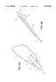
- FIG. 1shows an overview of the intubation device 2 according to one embodiment of the present invention.
- the intubation device 2generally includes a handle section 6 by which the device is grasped during use.
- the handleincludes a flushing port 26 for introducing fluids and/or gases to a flushing conduit (not shown in FIG. 1).
- the device 2also includes an illumination port 32 for delivering electromagnetic radiation to an illumination conduit (not shown in FIG. 1).
- the device 2includes an image-receiving port 34 for receiving images from an image-receiving conduit (not shown in FIG. 1).
- Both the flushing port 26 and the illumination port 32include threaded end sections for providing connection to a standard fluid/gas delivery device and an electromagnetic generation device, respectively.
- the image-receiving portterminates in a locking nut 36 for securing a fiber optic bundle (or electrical wire) within the image-receiving conduit.
- the image-receiving conduit, illumination conduit and flushing conduitconverge and are joined at the distal end of the device 2 at an endoscope tip 16.
- the endoscope tip 16protrudes a short distance beyond the distal end 14 of the tube 4.
- the position of the endoscope tip 16 and the distal end 14 of the tube 4can be adjusted by rotating a length-adjusting nut 20.
- the length-adjusting nut 20is rotationally affixed to the handle 6. Rotation of the length-adjusting nut 20 in a first direction advances a threaded length-adjustment member 24 away from the handle, which has the effect of advancing the distal end 14 of the tube past the endoscope tip 16. Rotation of the length-adjusting nut 20 in the opposite direction retracts the threaded length-adjustment member 24 into the handle 6, which has the effect of advancing the endoscope tip 16 out from the distal end 14 of the tube.
- the image-receiving conduit and the illumination conduitare joined together to form an imaging conduit.
- the imaging conduitis attached to a thumb piece 28, which, in turn, is attached to a thumb piece extension member 30. Together, the thumb piece 28 and the thumb piece extension member 30 constitute a manipulation member. Depression of thumb-piece 28 pushes the imaging conduit toward the distal end of the device.
- the flushing conduitis fixed to the handle 6. Also, as mentioned, the flushing conduit is joined to the illumination conduit and the image-receiving conduit (collectively forming the imaging conduit) at the endoscope tip 16. Thus, pressing on the thumb piece 28 pushes the endoscope tip 16 away from the handle 6 against the restraint of the flushing conduit which does not move.
- the imaging conduit and the flushing conduitare confined to the lumen of the endotracheal tube 4, this action has the end result of bowing the distal portions of the tube 4.
- the end of the tube 4can assume the curvature given by the dotted line "Y" shown in FIG. 1 when the thump piece 28 is actuated.
- FIG. 2(a)shows the configuration of the various conduits used in the intubation device without the endotracheal tube 4 disposed thereover.
- the conduitsinclude a flushing conduit 50 and an imaging conduit 52.
- the imaging conduitactually comprises two separate conduits--an illumination conduit and an image-receiving conduit. These conduits are joined at the endoscope tip 16.
- a sheath 54surrounds a substantial portion of the imaging conduit 52, leaving a prescribed portion of the distal end of the imaging conduit 52 uncovered.
- This sheathis made of a stiff plastic material, or other suitable material.
- the sheathhas the effect of increasing the rigidity of the portion of the imaging conduit 52 that it covers.
- this rigidity-enhanced portion of the devicewill bend less readily than the uncovered portion of the imaging conduit 52 when the user depresses the thumb piece 28.
- more acute curvaturescan be obtained by pressing the thumb piece 28 with a stronger force, and less acute curvatures can be obtained by depressing the thumb piece 28 with a weaker force.
- a rod 56 having a desired stiffnesscan be affixed to a selected length of the imaging conduit 52, as shown in FIG. 2(b).
- the rodcan comprises a metal wire, or a non-metallic strip of material (such as plastic).
- FIG. 2(b)shows the rod 56 attached to the exterior of the imaging conduit 52, but this rod can also be formed in the interior of the conduit (e.g., in one of the lumens of this conduit).
- the desired distribution of rigidity of the imaging conduit 52can be achieved by molding or machining the imaging conduit 52 such that it has at least two ranges of thicknesses.
- the imaging conduit 52can be made so that its distal end portion has a reduced thickness compared to the remainder of the conduit. This can be achieved by producing the imaging conduit in an extrusion process using two different extrusion dies for producing sections having corresponding different diameters.
- the desired distribution of rigiditycan be achieved by producing the imaging conduit using materials having different inherent rigidity. For instance, the proximal portion can be produced with a material having a higher rigidity compared to the distal portion.
- the tubecan be formed of any material of suitable rigidity.
- the tubecan be comprised of a malleable metallic material.
- the imaging conduit with this tube disposed thereincan be bent to a desired shape and the imaging conduit will retain this shape.
- the tubecan have resiliency.
- the imaging conduit with this tube disposed thereinwill spring back to its original shape when bent.
- the imaging conduitcan use a combination of the above-described techniques to provide a desired combination of resiliency and deformability.
- curvaturescan be achieved by varying the rigidity of the imaging conduit 52 along different portions of its length. Generally, as the rigidity-enhanced section of the imaging conduit 52 advances to encompass more of the distal end of the device, a progressively "tighter" curvature will be provided (i.e., having a smaller radius).
- the imaging conduit 52is joined to the flushing conduit 50 at the endoscope tip 16.
- One technique for joining these two conduitsis by means of a plastic wrap 66 which is heat shrunk around the two conduits to tightly bind these two conduits together.
- a plastic wrap 66which is heat shrunk around the two conduits to tightly bind these two conduits together.
- flushing portOne function of the fluids and/or gases delivered by the flushing port is to flush away various secretions and obstructions which obscure the field-of-view of the endoscope.
- the flushing conduit 50is connected to the imaging conduit 52 such that its outlet port 60 is retracted a short distance from the end of the imaging conduit 52. This ensures that the fluids and/or gases delivered by the flushing port do not "overshoot" the region directly in front of the imaging endoscope tip 16.
- two separate lumenscan be used to provide the image-receiving conduit and the illumination receiving conduit. These two conduits, in turn, can be bundled together in an outer shell.
- the region 68can comprise essentially empty space. It will be appreciated that the amount of this empty space can be decreased by ensuring that the outer shell fits the enclosed conduits snugly.
- the intubation deviceit is preferable that all reusable portions of the intubation device are kept sealed and separate from any portion of the device which comes in contact with the patient. For instance, it is contemplated that, in one embodiment, just the contents of the image-receiving conduit (e.g., including an imaging assembly) are reused. Thus, it is preferable that this portion of the system is separated from the patient. This can be ensured by sealing off the end of the image-receiving conduit with a window 62, which prevents the transmission of contaminants between the imaging assembly and the patient. After use, the entire intubation device except for the imaging assembly can be discarded.
- the image-receiving conduite.g., including an imaging assembly
- the illumination conduitincludes a light-transmission element 64, which can comprise a light pipe, an optical fiber, or like device.
- the light-transmission element 64is integrally attached to the imaging conduit, and thus is also discarded with the remainder of the intubation device.
- the use of separate ports for the image-receiving conduit and the light-transmission element 64provides notable benefits over other known designs in which transmitted light and received images pass through a single window. For instance, when a single window is used, the images projected by the light-transmission element 64 can create reflections on the shared window, which may degrade the images captured by the imaging assembly of the image-receiving conduit. Since the present design uses two separate conduits for image-receiving and illumination, the reflected image problem can be minimized.
- a window insert 63can be inserted into the distal end of the image-receiving conduit.
- the window insertincludes a window 62a in its distal end.
- a first section 67has a diameter sized such that the insert 63 fits snugly into the distal end of the image-receiving conduit.
- a second section 65has a larger diameter. Accordingly, when the window insert 63 is fully inserted into the image-receiving conduit, the second section 65 abuts against the face of the imaging-receiving conduit.
- the window insert 63can be formed of a suitable material, such as a plastic or metal (e.g., stainless steel).
- the image-receiving conduitincludes an image-receiving element 74 which communicates images to the proximal end of the device via cable 72. Together the element 74 and the cable 72 form an image-receiving assembly.
- the image-receiving element 74can comprise a CCD (charge-coupled device) or other type of imaging chip (e.g., a CMOS imaging chip) which communicates its images in electronic form over an electrical wire to the proximal end of the intubation device.
- imagescan be captured at the distal end by an optical element, such as one or more lenses, and transferred to the proximal end of the device via a fiber optic cable.
- the element 74can simply consist of the terminal end of a fiber optic cable (e.g., without a lens).
- a light pipecan be used to transfer the images to the proximal end of the intubation device.
- one or more lensescan be used in conjunction with a CCD device or chip.
- the dual-bored conduitcan include one of more guides for seating the image-receiving element 74 in a prescribed position relative to the window 62.
- the dual-bored conduitcan include an area of decreased diameter in proximity to the window 62. The diameter is sized such that the image-receiving element 74 is received and aligned in a prescribed position relative to the window 62 (e.g., such that the image-receiving element is held in abutment with the window 62 or is spaced a prescribed distance from the window 62).
- FIGS. 5(a), 5(b) and 5(c)show an exemplary method for attaching the endotracheal tube 4 to the handle 6.
- the terminal end of the threaded length-adjustment member 24flares out into a ring portion 82 having a diameter larger than the diameter of the threaded length-adjustment member 24.
- Diametrically opposed flanges 84 and 86extend outward from the ring 82.
- the flanges 84 and 86include a curved outer edge and a linear inner edge. The area between the inner linear edges defines a slot. (Note that FIG. 5(b) shows a view of FIG.
- the slot between the flanges 84 and 86is sized to snugly receive the wing 7 of the endotracheal tube 4.
- the ring 82, the flanges 84 and 86, and the nut 18collectively form a mounting member.
- the locking nut 18is slid from its position shown in FIG. 5(a) to the position shown in FIG. 5(c). In this position, the elongated slot 22 formed in the face of the locking nut 18 is aligned in parallel with the slot formed between the flanges 84 and 86. In this configuration, the wing 7 can be inserted through the slot 22 in the nut 18 and then firmly seated in the slot formed between the flanges 84 and 86. At this time, the adjustment nut 18 is rotated a quarter of a turn, thereby locking the endotracheal tube 4 onto the handle 6.
- FIG. 6(a)shows the structure housed inside the handle 6 (using dotted lines).
- the threaded length-adjustment member 24extends into the handle 6.
- the sheathed imaging conduit 54 and the flushing conduit 50extend through the threaded length-adjustment member 24.
- the sheathed imaging conduit 54splits into the illumination conduit 104 and the image-receiving conduit 102, which terminate in the ports 32 and 34, respectively.
- a thumb piece extension member 30extends from the thumb piece 28.
- the thumb piece extension memberforms a halved tube which cradles the sheathed imaging conduit 54.
- the sheathed imaging conduit 54is fixed to the thumb piece extension member 30 by adhesive or other form of bonding. Accordingly, pressing on the thumb piece 28 advances the imaging conduit 54 toward the distal end of the endoscope.
- the flushing conduit 50is held fixed to the handle 6. The force exerted on the imaging conduit 54 will thus cause a bowing in the imaging conduit, causing the distal end of the device to make an arc.
- the conduitscan be bundled together in alternative arrangements.
- the flushing conduitcan be bundled with the illumination conduit, or the flushing conduit can be bundled with the image-receiving conduit.
- all three conduitscan be bundled together, and a fourth conduit can be provided in the illustrated position of the flushing conduit.
- This fourth conduitcan comprise a lumen for introducing medical instruments.
- a solid flexible rodcan be used in place of this fourth conduit.
- conduits with respect to each otherthere are alternative ways to move the conduits with respect to each other.
- various types of levers, buttons, knobs, etc.can be used to move one conduit with respect to another.
- the inventionalso contemplates the use of a manipulation member which can pull on one conduit while holding another conduit fixed in placed, or can both pull and push on one conduit. This last embodiment can bend the distal end of the device in both directions Y and Y' shown in FIG. 1.
- the position of the endoscope tip 16 relative to the distal end 14 of the endotracheal tubecan be adjusted by rotating the length-adjustment nut 20.
- the length-adjustment nut 20has a lip 110 which engages and interlocks with a lip 112 of the handle 6. Furthermore, portions of the length-adjustment nut 20 are mated in threaded engagement with the length-adjustment member 24. Accordingly, when the length-adjustment nut 20 is rotated, the nut itself remains stationary, but the length-adjustment member 24 moves in the axial direction "C". Since the endotracheal tube 4 is mounted on the end of the length adjustment member 24, movement of the length-adjustment member 24 advances the distal end 14 of the endotracheal tube 4 relative to the endoscope tip 16.
- FIG. 7shows the exemplary configuration of the imaging receiving port 34.
- the port 34includes a locking nut 36 having an internal threaded surface 152.
- the nut 36also includes an internal post 150 having a central opening 170 for receiving a cable (e.g., an optical fiber or electrical wire).
- the port 34also includes a second member 37 having an external threaded surface 154 for engagement with the internal threaded surface 152 of the locking nut 36.
- the member 37also includes recess 160 for receiving the post 150.
- a resilient washer 156is located at the bottom surface of the recess 160.
- a hole 158 in the washer 156is concentric with a hole 159 in the member 37 and the hole 170 in the post 150.
- a cableis threaded through the holes 170, 158 and 159.
- the threaded nut 36is then tightened on the member 37.
- the post 150contacts the resilient washer 156 it deforms the washer 156, causing the diameter of the hole 158 to decrease, which, in turn, causes the resilient material of the washer to grip the cable.
- the cablecan comprise either a fiber optic cable or an electrical wire.
- gases and/or fluidscan be introduced into the flushing conduit 50 via the flushing port 26.
- the gases and/or fluidsexit the flushing conduit 50 at the port 60 (in FIG. 3).
- the gases and fluidsserve the beneficial role of removing obstructions (such as blood, mucus, vomitus, etc.) from the field-of-view of the imaging conduit 52.
- these flushing gases and/or fluidscan also be passed through the lumen of the endotracheal tube 4, outside the flushing and imaging conduits. This flow of gases and/or fluids can be introduced through an additional port 500 (shown in FIGS. 1 and 6(a)).
- a separate flushing conduit 501FIG.
- this supplemental flushing port 500can be provided which connects this supplemental flushing port 500 with the lumen of the endotracheal tube 4 via the lumen defined by the interior of the length-adjustment member 24.
- This optional flushing portoffers the ability to deliver greater quantities of gases and/or fluids more directly to the source of the obstruction in the patient's airway passage.
- the operatorcan detach the flushing supply from port 26 and attach the flushing supply to port 500 to remove the obstructions.
- the intubation deviceis prepared for use by attaching a fluid delivery apparatus and a light generation apparatus to the flushing conduit port 26 and the illumination conduit port 32, respectively.
- the image-receiving conduit port 34is connected to an input port of an image viewing apparatus, such as a conventional CRT monitor or LCD display.
- the endotracheal tube 4is then locked onto the handle 6 using the locking nut 18 as described above.
- the endoscope tip 16can then be moved to a desired position relative to the distal end 14 of the endotracheal tube 5. For instance, it is common to position the endoscope tip 16 so that it barely protrudes beyond the end 14 of the endotracheal tube 4.
- the intubation device 2 with the endotracheal tube 4 attached theretocan then be inserted into the mouth and airway passage of a patient.
- the operatoradvances the endotracheal tube 4 with the assistance of the intubation device 2, while observing the output monitor which shows the internal structure of the patient's airway passage.
- the tip 16 of the devicecan be maneuvered to avoid sensitive structure within the patient's airway passage by a combination of adjusting the position and orientation of the device and depressing the thumb piece 28.
- the intubation device 2can be removed, leaving the endotracheal tube in place.
- the intubation device 2is discarded after a single use, along with the used endotracheal tube.
- the only portion of the intubating scope and endotracheal tube that is not disposableis the imaging assembly within the image receiving conduit.
- the above-described device 2can be re-used after proper sterilization.
Landscapes
- Health & Medical Sciences (AREA)
- Life Sciences & Earth Sciences (AREA)
- Surgery (AREA)
- Radiology & Medical Imaging (AREA)
- Engineering & Computer Science (AREA)
- Pulmonology (AREA)
- Biophysics (AREA)
- Nuclear Medicine, Radiotherapy & Molecular Imaging (AREA)
- Optics & Photonics (AREA)
- Pathology (AREA)
- Physiology (AREA)
- Otolaryngology (AREA)
- Physics & Mathematics (AREA)
- Biomedical Technology (AREA)
- Heart & Thoracic Surgery (AREA)
- Medical Informatics (AREA)
- Molecular Biology (AREA)
- Animal Behavior & Ethology (AREA)
- General Health & Medical Sciences (AREA)
- Public Health (AREA)
- Veterinary Medicine (AREA)
- Endoscopes (AREA)
Abstract
Description
Claims (29)
Priority Applications (3)
| Application Number | Priority Date | Filing Date | Title |
|---|---|---|---|
| US08/963,593US5913816A (en) | 1997-10-31 | 1997-10-31 | Intubation device and method |
| PCT/US1998/022742WO1999022636A1 (en) | 1997-10-31 | 1998-10-28 | Intubation device and method |
| AU12016/99AAU1201699A (en) | 1997-10-31 | 1998-10-28 | Intubation device and method |
Applications Claiming Priority (1)
| Application Number | Priority Date | Filing Date | Title |
|---|---|---|---|
| US08/963,593US5913816A (en) | 1997-10-31 | 1997-10-31 | Intubation device and method |
Publications (1)
| Publication Number | Publication Date |
|---|---|
| US5913816Atrue US5913816A (en) | 1999-06-22 |
Family
ID=25507422
Family Applications (1)
| Application Number | Title | Priority Date | Filing Date |
|---|---|---|---|
| US08/963,593Expired - Fee RelatedUS5913816A (en) | 1997-10-31 | 1997-10-31 | Intubation device and method |
Country Status (3)
| Country | Link |
|---|---|
| US (1) | US5913816A (en) |
| AU (1) | AU1201699A (en) |
| WO (1) | WO1999022636A1 (en) |
Cited By (53)
| Publication number | Priority date | Publication date | Assignee | Title |
|---|---|---|---|---|
| EP1164916A1 (en)* | 2000-02-01 | 2002-01-02 | Edwin L. Adair | Surgical devices incorporating reduced area imaging devices |
| US20020108610A1 (en)* | 1996-02-26 | 2002-08-15 | Christopher Kent L. | Method and apparatus for endotracheal intubation using a light wand and curved guide |
| US6527703B2 (en) | 2001-06-14 | 2003-03-04 | Minitube Of America, Inc. | Device for sow-intra-uterine insemination and embryo transfer |
| US6533720B1 (en) | 2001-01-17 | 2003-03-18 | Avtar S. Dhindsa | Modular endoscope valve assembly and method |
| US6619954B2 (en)* | 2001-11-09 | 2003-09-16 | The Timao Group, Inc. | Bundled optical and fluid conduits |
| US20040152949A1 (en)* | 2002-12-02 | 2004-08-05 | Scott Laboratories Inc. | Systems and methods for providing gastrointestinal pain management |
| US6786865B2 (en) | 2001-01-17 | 2004-09-07 | Innon Holdings, Llc | Endoscope valve assembly and method |
| US6840903B2 (en) | 2002-03-21 | 2005-01-11 | Nuvista Technology Corporation | Laryngoscope with image sensor |
| US20050139220A1 (en)* | 1996-02-26 | 2005-06-30 | Evergreen Medical Incorporated | Method and apparatus for ventilation / oxygenation during guided insertion of an endotracheal tube |
| US20060009680A1 (en)* | 2001-01-17 | 2006-01-12 | Innon Holdings, Inc. | Endoscope valve assembly and method |
| US20060025650A1 (en)* | 2002-10-03 | 2006-02-02 | Oren Gavriely | Tube for inspecting internal organs of a body |
| USD519634S1 (en) | 2003-12-08 | 2006-04-25 | Innon Holdings, Llc | Valve assembly |
| US20070179342A1 (en)* | 2006-01-12 | 2007-08-02 | Kb Port Llc | Wireless Laryngoscope with Internal Antennae and One Piece Construction Adapted for Laryngoscopy Training |
| US20090032021A1 (en)* | 2005-12-16 | 2009-02-05 | Dominik Lirsch | Jet-Endoscope |
| US20090048654A1 (en)* | 2007-08-15 | 2009-02-19 | Wilson-Cook Medical Inc. | Deployment System for Soft Stents |
| US20090050146A1 (en)* | 2007-08-23 | 2009-02-26 | The Cleveland Clinic Foundation | Apparatus and method for intubating an airway of a patient |
| US20090192350A1 (en)* | 2008-01-28 | 2009-07-30 | Mauricio Mejia | Wireless video stylet with display mounted to laryngoscope blade and method for using the same |
| US20090192355A1 (en)* | 2008-01-28 | 2009-07-30 | Mauricio Mejia | Scope for managing difficult pathways and method to improve visibility of the same |
| US20100094090A1 (en)* | 2008-01-28 | 2010-04-15 | Mauricio Mejia | Self-cleaning wireless video stylet with display mounted to laryngoscope blade and method for using the same |
| US20100199999A1 (en)* | 2009-02-06 | 2010-08-12 | Vazales Brad E | Methods for cleaning endotracheal tubes |
| US8157919B2 (en) | 2009-02-06 | 2012-04-17 | Endoclear, Llc | Methods for removing debris from medical tubes |
| US20120259173A1 (en)* | 2011-04-05 | 2012-10-11 | Nellcor Puritan Bennett Llc | Visualization device and holder for use with a tracheal tube |
| US20130060089A1 (en)* | 2010-05-13 | 2013-03-07 | Aircraft Medical Limited | Laryngoscope insertion section structure |
| US20130291321A1 (en)* | 2013-05-07 | 2013-11-07 | The Xim Group, Llc | Tube Squeegee |
| USD716841S1 (en) | 2012-09-07 | 2014-11-04 | Covidien Lp | Display screen with annotate file icon |
| USD717340S1 (en) | 2012-09-07 | 2014-11-11 | Covidien Lp | Display screen with enteral feeding icon |
| US8885034B2 (en) | 1997-10-06 | 2014-11-11 | Micro-Imaging Solutions Llc | Reduced area imaging device incorporated within endoscopic devices |
| US8998798B2 (en) | 2010-12-29 | 2015-04-07 | Covidien Lp | Multi-lumen tracheal tube with visualization device |
| USD735343S1 (en) | 2012-09-07 | 2015-07-28 | Covidien Lp | Console |
| US9155854B2 (en) | 2011-08-31 | 2015-10-13 | Covidien Lp | Tracheal tube with visualization device and integrated flushing system |
| US9198835B2 (en) | 2012-09-07 | 2015-12-01 | Covidien Lp | Catheter with imaging assembly with placement aid and related methods therefor |
| US20160058267A1 (en)* | 2008-12-10 | 2016-03-03 | Ambu A/S | Endoscope bending section control mechanism |
| US9433339B2 (en) | 2010-09-08 | 2016-09-06 | Covidien Lp | Catheter with imaging assembly and console with reference library and related methods therefor |
| US9445714B2 (en) | 2010-03-29 | 2016-09-20 | Endoclear Llc | Endotracheal tube coupling adapters |
| WO2016176608A1 (en)* | 2015-04-30 | 2016-11-03 | Veritas Medical, L.L.C. | Methods and apparatus to deliver therapeutic non-ultraviolet electromagnetic radiation for an endotracheal tube |
| CN106178231A (en)* | 2016-08-03 | 2016-12-07 | 武汉福脉医疗科技有限公司 | Medical double-deck high pressure resistant sacculus and preparation method thereof |
| US9517184B2 (en) | 2012-09-07 | 2016-12-13 | Covidien Lp | Feeding tube with insufflation device and related methods therefor |
| US9526856B2 (en) | 2011-12-15 | 2016-12-27 | The Board Of Trustees Of The Leland Stanford Junior University | Devices and methods for preventing tracheal aspiration |
| US9622651B2 (en) | 2012-01-27 | 2017-04-18 | Kbport Llc | Wireless laryngoscope simulator with onboard event recording adapted for laryngoscopy training |
| US9770194B2 (en) | 2013-11-05 | 2017-09-26 | Ciel Medical, Inc. | Devices and methods for airway measurement |
| US9840266B2 (en) | 2013-10-09 | 2017-12-12 | Glidemachines Llc | Apparatus and method for towing a load by a person |
| US10004863B2 (en) | 2012-12-04 | 2018-06-26 | Endoclear Llc | Closed suction cleaning devices, systems and methods |
| US10016575B2 (en) | 2014-06-03 | 2018-07-10 | Endoclear Llc | Cleaning devices, systems and methods |
| US10149602B2 (en) | 2011-07-11 | 2018-12-11 | Ambu A/S | Endobronchial tube with integrated image sensor and a cleaning nozzle arrangement |
| US10245402B2 (en) | 2011-07-11 | 2019-04-02 | Ambu A/S | Endobronchial tube with integrated image sensor |
| US10478054B2 (en) | 2016-02-12 | 2019-11-19 | Ambu A/S | Endotracheal tube with visualization capabilities and a laryngeal mask |
| US10722322B2 (en) | 2010-03-29 | 2020-07-28 | Endoclear Llc | Distal airway cleaning devices |
| US11000452B2 (en)* | 2015-07-06 | 2021-05-11 | Werd, Llc | Temporary tubes and a system for placing same in a patient |
| US11166627B2 (en) | 2018-01-26 | 2021-11-09 | Ambu A/S | Method for fixation of a wire portion of an endoscope, and an endoscope |
| US11291355B2 (en) | 2018-01-19 | 2022-04-05 | Ambu A/S | Method for fixation of a wire portion of an endoscope, and an endoscope |
| US11553833B2 (en) | 2017-03-08 | 2023-01-17 | Ambu A/S | Handle for an endoscope |
| US11642014B2 (en) | 2017-03-08 | 2023-05-09 | Ambu A/S | Handle for an endoscope |
| WO2024118498A3 (en)* | 2022-11-29 | 2024-08-02 | Cronin Arthur | Device and method for pneumatically or hydraulically shapable stylet for an endotracheal breathing tube |
Citations (32)
| Publication number | Priority date | Publication date | Assignee | Title |
|---|---|---|---|---|
| US3669098A (en)* | 1968-10-05 | 1972-06-13 | Olympus Optical Co | Endotracheal tube |
| US3677262A (en)* | 1970-07-23 | 1972-07-18 | Henry J Zukowski | Surgical instrument illuminating endotracheal tube inserter |
| US3776222A (en)* | 1971-12-23 | 1973-12-04 | Lurosso A | Fiber optic entubator and method of entubation of the trachea through the nasopharynx |
| US3913568A (en)* | 1973-01-22 | 1975-10-21 | American Optical Corp | Nasopharyngoscope |
| US4041936A (en)* | 1975-04-23 | 1977-08-16 | Medical Engineering Corporation | Bronchoscopy tube |
| US4086919A (en)* | 1976-07-09 | 1978-05-02 | Bullard James R | Laryngoscope |
| US4360008A (en)* | 1980-09-02 | 1982-11-23 | Corazzelli Jr Frank G | Laryngoscope |
| US4567882A (en)* | 1982-12-06 | 1986-02-04 | Vanderbilt University | Method for locating the illuminated tip of an endotracheal tube |
| US4580556A (en)* | 1984-04-13 | 1986-04-08 | Kondur Prabhakar R | Adaptor for endotracheal intubation |
| US4742819A (en)* | 1987-03-23 | 1988-05-10 | George Gordon P | Intubating scope with camera and screen |
| US4773394A (en)* | 1987-10-14 | 1988-09-27 | Reichstein Irving P | Upper gastrointestinal endoscope intubator |
| US4795430A (en)* | 1988-01-15 | 1989-01-03 | Corpak, Inc. | Device for intubation of percutaneous endoscopic ostomy |
| US4846153A (en)* | 1988-06-10 | 1989-07-11 | George Berci | Intubating video endoscope |
| US4900306A (en)* | 1988-01-15 | 1990-02-13 | Corpak, Inc. | Device for intubation of percutaneous endoscopic ostomy |
| US4981471A (en)* | 1988-01-15 | 1991-01-01 | Corpak, Inc. | Device for intubation of percutaneous endoscopic ostomy |
| US4982729A (en)* | 1989-02-10 | 1991-01-08 | Wu Tzu Lang | Rigid fiberoptic intubating laryngoscope |
| US5016614A (en)* | 1985-11-07 | 1991-05-21 | Macallister Niall P | Endotracheal intubation apparatus |
| US5174283A (en)* | 1989-11-08 | 1992-12-29 | Parker Jeffrey D | Blind orolaryngeal and oroesophageal guiding and aiming device |
| US5183031A (en)* | 1991-05-13 | 1993-02-02 | Rossoff Leonard J | Fiberoptic intubating laryngoscope |
| US5203320A (en)* | 1987-03-24 | 1993-04-20 | Augustine Medical, Inc. | Tracheal intubation guide |
| US5327881A (en)* | 1993-02-26 | 1994-07-12 | Beth Israel Hospital Association | Fiberoptic intubating stylet |
| US5337735A (en)* | 1992-12-28 | 1994-08-16 | Albert Salerno | Fiber-lighted stylet |
| US5363838A (en)* | 1992-12-09 | 1994-11-15 | George Gordon P | Fiberoptic intubating scope with camera and lightweight portable screen and method of using same |
| US5365940A (en)* | 1993-06-22 | 1994-11-22 | Advanced Medical Concepts, Inc. | Endotracheal tube having tongue-contacting temperature sensor |
| US5400771A (en)* | 1993-01-21 | 1995-03-28 | Pirak; Leon | Endotracheal intubation assembly and related method |
| US5431152A (en)* | 1993-09-21 | 1995-07-11 | Flam; Gary H. | Oral fiberoptic intubating apparatus and method |
| US5551946A (en)* | 1994-05-17 | 1996-09-03 | Bullard; James R. | Multifunctional intubating guide stylet and laryngoscope |
| US5607386A (en)* | 1993-09-21 | 1997-03-04 | Flam; Gary H. | Malleable fiberoptic intubating stylet and method |
| US5620408A (en)* | 1995-04-14 | 1997-04-15 | Vennes; Jack A. | Endoscopic over-tube |
| US5643174A (en)* | 1993-08-18 | 1997-07-01 | Sumitomo Bakelite Company Limited | Endoscopic guide tube with embedded coil spring |
| US5645519A (en)* | 1994-03-18 | 1997-07-08 | Jai S. Lee | Endoscopic instrument for controlled introduction of tubular members in the body and methods therefor |
| US5676635A (en)* | 1995-08-30 | 1997-10-14 | Levin; Bruce | Instrument for insertion of an endotracheal tube |
Family Cites Families (3)
| Publication number | Priority date | Publication date | Assignee | Title |
|---|---|---|---|---|
| US3788304A (en)* | 1971-06-15 | 1974-01-29 | Olympus Optical Co | Endoscope |
| WO1991012044A1 (en)* | 1990-02-14 | 1991-08-22 | Adair Edwin Lloyd | Endotracheal tube intubation assist device |
| AU6158196A (en)* | 1995-06-07 | 1996-12-30 | Robert T. Chilcoat | Articulated endospcope with specific advantages for laryngos copy |
- 1997
- 1997-10-31USUS08/963,593patent/US5913816A/ennot_activeExpired - Fee Related
- 1998
- 1998-10-28AUAU12016/99Apatent/AU1201699A/ennot_activeAbandoned
- 1998-10-28WOPCT/US1998/022742patent/WO1999022636A1/enactiveApplication Filing
Patent Citations (35)
| Publication number | Priority date | Publication date | Assignee | Title |
|---|---|---|---|---|
| US3669098A (en)* | 1968-10-05 | 1972-06-13 | Olympus Optical Co | Endotracheal tube |
| US3677262A (en)* | 1970-07-23 | 1972-07-18 | Henry J Zukowski | Surgical instrument illuminating endotracheal tube inserter |
| US3776222A (en)* | 1971-12-23 | 1973-12-04 | Lurosso A | Fiber optic entubator and method of entubation of the trachea through the nasopharynx |
| US3913568A (en)* | 1973-01-22 | 1975-10-21 | American Optical Corp | Nasopharyngoscope |
| US4041936A (en)* | 1975-04-23 | 1977-08-16 | Medical Engineering Corporation | Bronchoscopy tube |
| US4086919A (en)* | 1976-07-09 | 1978-05-02 | Bullard James R | Laryngoscope |
| US4360008A (en)* | 1980-09-02 | 1982-11-23 | Corazzelli Jr Frank G | Laryngoscope |
| US4567882A (en)* | 1982-12-06 | 1986-02-04 | Vanderbilt University | Method for locating the illuminated tip of an endotracheal tube |
| US4580556A (en)* | 1984-04-13 | 1986-04-08 | Kondur Prabhakar R | Adaptor for endotracheal intubation |
| US5016614A (en)* | 1985-11-07 | 1991-05-21 | Macallister Niall P | Endotracheal intubation apparatus |
| US4742819A (en)* | 1987-03-23 | 1988-05-10 | George Gordon P | Intubating scope with camera and screen |
| US5203320A (en)* | 1987-03-24 | 1993-04-20 | Augustine Medical, Inc. | Tracheal intubation guide |
| US4773394A (en)* | 1987-10-14 | 1988-09-27 | Reichstein Irving P | Upper gastrointestinal endoscope intubator |
| US4795430A (en)* | 1988-01-15 | 1989-01-03 | Corpak, Inc. | Device for intubation of percutaneous endoscopic ostomy |
| US4900306A (en)* | 1988-01-15 | 1990-02-13 | Corpak, Inc. | Device for intubation of percutaneous endoscopic ostomy |
| US4981471A (en)* | 1988-01-15 | 1991-01-01 | Corpak, Inc. | Device for intubation of percutaneous endoscopic ostomy |
| US4846153A (en)* | 1988-06-10 | 1989-07-11 | George Berci | Intubating video endoscope |
| US4982729A (en)* | 1989-02-10 | 1991-01-08 | Wu Tzu Lang | Rigid fiberoptic intubating laryngoscope |
| US5339805A (en)* | 1989-11-08 | 1994-08-23 | Parker Jeffrey D | Blind orolaryngeal and oroesophageal guiding and aiming device |
| US5174283A (en)* | 1989-11-08 | 1992-12-29 | Parker Jeffrey D | Blind orolaryngeal and oroesophageal guiding and aiming device |
| US5183031A (en)* | 1991-05-13 | 1993-02-02 | Rossoff Leonard J | Fiberoptic intubating laryngoscope |
| US5363838A (en)* | 1992-12-09 | 1994-11-15 | George Gordon P | Fiberoptic intubating scope with camera and lightweight portable screen and method of using same |
| US5363838B1 (en)* | 1992-12-09 | 2000-03-28 | Gordon P George | Fiberoptic intubating scope with camera and lightweight portable screen and method of using same |
| US5337735A (en)* | 1992-12-28 | 1994-08-16 | Albert Salerno | Fiber-lighted stylet |
| US5400771A (en)* | 1993-01-21 | 1995-03-28 | Pirak; Leon | Endotracheal intubation assembly and related method |
| US5327881A (en)* | 1993-02-26 | 1994-07-12 | Beth Israel Hospital Association | Fiberoptic intubating stylet |
| US5365940A (en)* | 1993-06-22 | 1994-11-22 | Advanced Medical Concepts, Inc. | Endotracheal tube having tongue-contacting temperature sensor |
| US5643174A (en)* | 1993-08-18 | 1997-07-01 | Sumitomo Bakelite Company Limited | Endoscopic guide tube with embedded coil spring |
| US5431152A (en)* | 1993-09-21 | 1995-07-11 | Flam; Gary H. | Oral fiberoptic intubating apparatus and method |
| US5607386A (en)* | 1993-09-21 | 1997-03-04 | Flam; Gary H. | Malleable fiberoptic intubating stylet and method |
| US5645519A (en)* | 1994-03-18 | 1997-07-08 | Jai S. Lee | Endoscopic instrument for controlled introduction of tubular members in the body and methods therefor |
| US5665052A (en)* | 1994-05-17 | 1997-09-09 | Bullard; James Roger | Multifunctional intubating guide stylet and laryngoscope |
| US5551946A (en)* | 1994-05-17 | 1996-09-03 | Bullard; James R. | Multifunctional intubating guide stylet and laryngoscope |
| US5620408A (en)* | 1995-04-14 | 1997-04-15 | Vennes; Jack A. | Endoscopic over-tube |
| US5676635A (en)* | 1995-08-30 | 1997-10-14 | Levin; Bruce | Instrument for insertion of an endotracheal tube |
Cited By (97)
| Publication number | Priority date | Publication date | Assignee | Title |
|---|---|---|---|---|
| US20020108610A1 (en)* | 1996-02-26 | 2002-08-15 | Christopher Kent L. | Method and apparatus for endotracheal intubation using a light wand and curved guide |
| US20050139220A1 (en)* | 1996-02-26 | 2005-06-30 | Evergreen Medical Incorporated | Method and apparatus for ventilation / oxygenation during guided insertion of an endotracheal tube |
| US6860264B2 (en)* | 1996-02-26 | 2005-03-01 | Evergreen Medical Incorporated | Method and apparatus for endotracheal intubation using a light wand and curved guide |
| US9307895B2 (en) | 1997-10-06 | 2016-04-12 | Micro-Imaging Solutions, Llc | Reduced area imaging device incorporated within endoscopic devices |
| US9198565B2 (en) | 1997-10-06 | 2015-12-01 | Micro-Imaging Solutions | Reduced area imaging device incorporated within endoscopic devices |
| US9186052B1 (en) | 1997-10-06 | 2015-11-17 | Micro-Imagaing Solutions | Reduced area imaging device incorporated within endoscopic devices |
| US8885034B2 (en) | 1997-10-06 | 2014-11-11 | Micro-Imaging Solutions Llc | Reduced area imaging device incorporated within endoscopic devices |
| US9667896B2 (en) | 1997-10-06 | 2017-05-30 | Cellect Llc | Reduced area imaging device incorporated within endoscopic devices |
| EP1164916A1 (en)* | 2000-02-01 | 2002-01-02 | Edwin L. Adair | Surgical devices incorporating reduced area imaging devices |
| US6786865B2 (en) | 2001-01-17 | 2004-09-07 | Innon Holdings, Llc | Endoscope valve assembly and method |
| US6666818B2 (en) | 2001-01-17 | 2003-12-23 | Innon Holdings, Llc | Modular endoscope valve assembly and method |
| US20060009680A1 (en)* | 2001-01-17 | 2006-01-12 | Innon Holdings, Inc. | Endoscope valve assembly and method |
| US6533720B1 (en) | 2001-01-17 | 2003-03-18 | Avtar S. Dhindsa | Modular endoscope valve assembly and method |
| US6527703B2 (en) | 2001-06-14 | 2003-03-04 | Minitube Of America, Inc. | Device for sow-intra-uterine insemination and embryo transfer |
| US7108505B2 (en) | 2001-11-09 | 2006-09-19 | The Timao Group, Inc. | Bundled optical and fluid conduits |
| US20030198916A1 (en)* | 2001-11-09 | 2003-10-23 | Timao Group, Inc. | Bundled optical and fluid conduits |
| US6619954B2 (en)* | 2001-11-09 | 2003-09-16 | The Timao Group, Inc. | Bundled optical and fluid conduits |
| US20050043590A1 (en)* | 2002-03-21 | 2005-02-24 | Mazzei William J. | Laryngoscope with image sensor |
| US6840903B2 (en) | 2002-03-21 | 2005-01-11 | Nuvista Technology Corporation | Laryngoscope with image sensor |
| US20060025650A1 (en)* | 2002-10-03 | 2006-02-02 | Oren Gavriely | Tube for inspecting internal organs of a body |
| US20040152949A1 (en)* | 2002-12-02 | 2004-08-05 | Scott Laboratories Inc. | Systems and methods for providing gastrointestinal pain management |
| US6962564B2 (en) | 2002-12-02 | 2005-11-08 | Hickle Randall S | Systems and methods for providing gastrointestinal pain management |
| USD519634S1 (en) | 2003-12-08 | 2006-04-25 | Innon Holdings, Llc | Valve assembly |
| US20090032021A1 (en)* | 2005-12-16 | 2009-02-05 | Dominik Lirsch | Jet-Endoscope |
| US20070179342A1 (en)* | 2006-01-12 | 2007-08-02 | Kb Port Llc | Wireless Laryngoscope with Internal Antennae and One Piece Construction Adapted for Laryngoscopy Training |
| US20090048654A1 (en)* | 2007-08-15 | 2009-02-19 | Wilson-Cook Medical Inc. | Deployment System for Soft Stents |
| US20090050146A1 (en)* | 2007-08-23 | 2009-02-26 | The Cleveland Clinic Foundation | Apparatus and method for intubating an airway of a patient |
| US20090192350A1 (en)* | 2008-01-28 | 2009-07-30 | Mauricio Mejia | Wireless video stylet with display mounted to laryngoscope blade and method for using the same |
| US20090192355A1 (en)* | 2008-01-28 | 2009-07-30 | Mauricio Mejia | Scope for managing difficult pathways and method to improve visibility of the same |
| US20100094090A1 (en)* | 2008-01-28 | 2010-04-15 | Mauricio Mejia | Self-cleaning wireless video stylet with display mounted to laryngoscope blade and method for using the same |
| US8888683B2 (en) | 2008-01-28 | 2014-11-18 | Mauricio Mejia | Modifications in endoscope apparatus, using fluid and gas dynamics, and methods for improving visibility during endoscopy |
| US20160058267A1 (en)* | 2008-12-10 | 2016-03-03 | Ambu A/S | Endoscope bending section control mechanism |
| US10624529B2 (en) | 2008-12-10 | 2020-04-21 | Ambu A/S | Endoscope bending section control mechanism |
| US10149605B2 (en)* | 2008-12-10 | 2018-12-11 | Ambu A/S | Endoscope bending section control mechanism |
| US10165931B2 (en) | 2008-12-10 | 2019-01-01 | Ambu A/S | Endoscope bending section control mechanism |
| US9095286B2 (en) | 2009-02-06 | 2015-08-04 | Endoclear Llc | Body-inserted tube cleaning |
| US8468637B2 (en) | 2009-02-06 | 2013-06-25 | Endoclear Llc | Mechanically-actuated endotracheal tube cleaning device |
| US8601633B2 (en) | 2009-02-06 | 2013-12-10 | Endoclear Llc | Cleaning of body-inserted medical tubes |
| US8458844B2 (en) | 2009-02-06 | 2013-06-11 | Endoclear, Llc | Medical tube cleaning apparatus |
| US10441380B2 (en) | 2009-02-06 | 2019-10-15 | Endoclear Llc | Body-inserted tube cleaning |
| US20100199999A1 (en)* | 2009-02-06 | 2010-08-12 | Vazales Brad E | Methods for cleaning endotracheal tubes |
| US8534287B2 (en) | 2009-02-06 | 2013-09-17 | Endoclear, Llc | Methods for tracheostomy visualization |
| US9579012B2 (en) | 2009-02-06 | 2017-02-28 | Endoclear Llc | Visualized endotracheal tube placement systems |
| US9962233B2 (en) | 2009-02-06 | 2018-05-08 | Endoclear Llc | Body-inserted tube cleaning |
| US8382908B2 (en) | 2009-02-06 | 2013-02-26 | Endoclear, Llc | Methods for cleaning endotracheal tubes |
| US8381345B2 (en) | 2009-02-06 | 2013-02-26 | Endoclear, Llc | Devices for cleaning endotracheal tubes |
| US9907624B2 (en) | 2009-02-06 | 2018-03-06 | Endoclear Llc | Body-inserted tube cleaning with suction |
| US9855111B2 (en) | 2009-02-06 | 2018-01-02 | Endoclear Llc | Methods of removing biofilm from endotracheal tubes |
| US10682203B2 (en) | 2009-02-06 | 2020-06-16 | Endoclear Llc | Methods of cleaning endotracheal tubes including light treatment |
| US8157919B2 (en) | 2009-02-06 | 2012-04-17 | Endoclear, Llc | Methods for removing debris from medical tubes |
| US9332891B2 (en) | 2009-02-06 | 2016-05-10 | Endoclear Llc | Tracheostomy visualization |
| US9386907B2 (en) | 2009-02-06 | 2016-07-12 | Endoclear Llc | Visualization systems and methods |
| US9398837B2 (en) | 2009-02-06 | 2016-07-26 | Endoclear Llc | Methods for confirming placement of endotracheal tubes |
| US10722322B2 (en) | 2010-03-29 | 2020-07-28 | Endoclear Llc | Distal airway cleaning devices |
| US9445714B2 (en) | 2010-03-29 | 2016-09-20 | Endoclear Llc | Endotracheal tube coupling adapters |
| US9775505B2 (en)* | 2010-05-13 | 2017-10-03 | Aircraft Medical Limited | Laryngoscope insertion section structure |
| US11510563B2 (en) | 2010-05-13 | 2022-11-29 | Covidien Ag | Laryngoscope insertion section structure |
| US10758114B2 (en) | 2010-05-13 | 2020-09-01 | Aircraft Medical Limited | Laryngoscope insertion section structure |
| US20130060089A1 (en)* | 2010-05-13 | 2013-03-07 | Aircraft Medical Limited | Laryngoscope insertion section structure |
| US10272016B2 (en) | 2010-09-08 | 2019-04-30 | Kpr U.S., Llc | Catheter with imaging assembly |
| US9538908B2 (en) | 2010-09-08 | 2017-01-10 | Covidien Lp | Catheter with imaging assembly |
| US9585813B2 (en) | 2010-09-08 | 2017-03-07 | Covidien Lp | Feeding tube system with imaging assembly and console |
| US9433339B2 (en) | 2010-09-08 | 2016-09-06 | Covidien Lp | Catheter with imaging assembly and console with reference library and related methods therefor |
| US8998798B2 (en) | 2010-12-29 | 2015-04-07 | Covidien Lp | Multi-lumen tracheal tube with visualization device |
| US20120259173A1 (en)* | 2011-04-05 | 2012-10-11 | Nellcor Puritan Bennett Llc | Visualization device and holder for use with a tracheal tube |
| US9211060B2 (en)* | 2011-04-05 | 2015-12-15 | Covidien Lp | Visualization device and holder for use with a tracheal tube |
| US10406309B2 (en) | 2011-07-11 | 2019-09-10 | Ambu A/S | Endobronchial tube with integrated image sensor and a cleaning nozzle arrangement |
| US10888679B2 (en) | 2011-07-11 | 2021-01-12 | Ambu A/S | Endobronchial tube with integrated image sensor |
| US10149602B2 (en) | 2011-07-11 | 2018-12-11 | Ambu A/S | Endobronchial tube with integrated image sensor and a cleaning nozzle arrangement |
| US10245402B2 (en) | 2011-07-11 | 2019-04-02 | Ambu A/S | Endobronchial tube with integrated image sensor |
| US9155854B2 (en) | 2011-08-31 | 2015-10-13 | Covidien Lp | Tracheal tube with visualization device and integrated flushing system |
| US9526856B2 (en) | 2011-12-15 | 2016-12-27 | The Board Of Trustees Of The Leland Stanford Junior University | Devices and methods for preventing tracheal aspiration |
| US9622651B2 (en) | 2012-01-27 | 2017-04-18 | Kbport Llc | Wireless laryngoscope simulator with onboard event recording adapted for laryngoscopy training |
| USD735343S1 (en) | 2012-09-07 | 2015-07-28 | Covidien Lp | Console |
| US9198835B2 (en) | 2012-09-07 | 2015-12-01 | Covidien Lp | Catheter with imaging assembly with placement aid and related methods therefor |
| US9517184B2 (en) | 2012-09-07 | 2016-12-13 | Covidien Lp | Feeding tube with insufflation device and related methods therefor |
| USD717340S1 (en) | 2012-09-07 | 2014-11-11 | Covidien Lp | Display screen with enteral feeding icon |
| USD716841S1 (en) | 2012-09-07 | 2014-11-04 | Covidien Lp | Display screen with annotate file icon |
| US10821249B2 (en) | 2012-12-04 | 2020-11-03 | Endoclear Llc | Closed suction cleaning devices, systems and methods |
| US10004863B2 (en) | 2012-12-04 | 2018-06-26 | Endoclear Llc | Closed suction cleaning devices, systems and methods |
| US11173266B2 (en) | 2012-12-04 | 2021-11-16 | Endoclear Llc | Closed suction cleaning devices, systems and methods |
| US20130291321A1 (en)* | 2013-05-07 | 2013-11-07 | The Xim Group, Llc | Tube Squeegee |
| US9840266B2 (en) | 2013-10-09 | 2017-12-12 | Glidemachines Llc | Apparatus and method for towing a load by a person |
| US9770194B2 (en) | 2013-11-05 | 2017-09-26 | Ciel Medical, Inc. | Devices and methods for airway measurement |
| US10016575B2 (en) | 2014-06-03 | 2018-07-10 | Endoclear Llc | Cleaning devices, systems and methods |
| US10850062B2 (en) | 2014-06-03 | 2020-12-01 | Endoclear Llc | Cleaning devices, systems and methods |
| WO2016176608A1 (en)* | 2015-04-30 | 2016-11-03 | Veritas Medical, L.L.C. | Methods and apparatus to deliver therapeutic non-ultraviolet electromagnetic radiation for an endotracheal tube |
| US10870015B2 (en) | 2015-04-30 | 2020-12-22 | Light Line Medical, Inc. | Methods and apparatus to deliver therapeutic non-ultraviolet electromagnetic radiation for an endotracheal tube |
| US11000452B2 (en)* | 2015-07-06 | 2021-05-11 | Werd, Llc | Temporary tubes and a system for placing same in a patient |
| US10478054B2 (en) | 2016-02-12 | 2019-11-19 | Ambu A/S | Endotracheal tube with visualization capabilities and a laryngeal mask |
| CN106178231A (en)* | 2016-08-03 | 2016-12-07 | 武汉福脉医疗科技有限公司 | Medical double-deck high pressure resistant sacculus and preparation method thereof |
| US11553833B2 (en) | 2017-03-08 | 2023-01-17 | Ambu A/S | Handle for an endoscope |
| US11642014B2 (en) | 2017-03-08 | 2023-05-09 | Ambu A/S | Handle for an endoscope |
| US11291355B2 (en) | 2018-01-19 | 2022-04-05 | Ambu A/S | Method for fixation of a wire portion of an endoscope, and an endoscope |
| US11832792B2 (en) | 2018-01-19 | 2023-12-05 | Ambu A/S | Method for fixation of a wire portion of an endoscope, and an endoscope |
| US11166627B2 (en) | 2018-01-26 | 2021-11-09 | Ambu A/S | Method for fixation of a wire portion of an endoscope, and an endoscope |
| WO2024118498A3 (en)* | 2022-11-29 | 2024-08-02 | Cronin Arthur | Device and method for pneumatically or hydraulically shapable stylet for an endotracheal breathing tube |
Also Published As
| Publication number | Publication date |
|---|---|
| WO1999022636A1 (en) | 1999-05-14 |
| AU1201699A (en) | 1999-05-24 |
Similar Documents
| Publication | Publication Date | Title |
|---|---|---|
| US5913816A (en) | Intubation device and method | |
| EP1667749B1 (en) | System of accessories for use with bronchoscopes | |
| US5460168A (en) | Endoscope cover assembly and cover-system endoscope | |
| US5329940A (en) | Endotracheal tube intubation assist device | |
| US7946981B1 (en) | Two-piece video laryngoscope | |
| US11678794B2 (en) | Side loading articulating laryngeal access system | |
| US5676635A (en) | Instrument for insertion of an endotracheal tube | |
| US5846183A (en) | Articulated endoscope with specific advantages for laryngoscopy | |
| US20100094090A1 (en) | Self-cleaning wireless video stylet with display mounted to laryngoscope blade and method for using the same | |
| US20070049794A1 (en) | Visualization stylet for medical device applications having self-contained power source | |
| EP2316328A1 (en) | System of accessories for use with bronchoscopes | |
| US20210260320A1 (en) | Intubating endoscopic device | |
| US20070015961A1 (en) | Method for collecting/transporting a medical capsule and endoscopic apparatus for the method | |
| JP2017537761A (en) | Intubation device | |
| JP2012523874A (en) | Laryngoscope | |
| US20050192481A1 (en) | Laryngoscope and camera coupling | |
| US20200171256A1 (en) | Intubation Systems and Methods | |
| WO2018064185A1 (en) | Intubating endoscopic device | |
| JP2002000732A (en) | Auxiliary device for endotracheal intubation | |
| JPH0747052A (en) | Cover type endoscope | |
| CN113520291A (en) | A fully wrapped laryngoscope and laryngoscope blade | |
| JP4683282B2 (en) | Endoscope device | |
| US20250072741A1 (en) | Video laryngoscopic tracheoscope | |
| JPH1142207A (en) | Parent-child endoscope device | |
| US20080015414A1 (en) | Combined Dispenser and Mouthpiece for Endoscope |
Legal Events
| Date | Code | Title | Description |
|---|---|---|---|
| AS | Assignment | Owner name:IMAGYN MEDICAL TECHNOLOGIES, INC., CALIFORNIA Free format text:ASSIGNMENT OF ASSIGNORS INTEREST;ASSIGNORS:SANDERS, GARY H.;BOWERS, FRANK;INGLE, AARON;AND OTHERS;REEL/FRAME:009144/0586;SIGNING DATES FROM 19980401 TO 19980413 | |
| AS | Assignment | Owner name:BT COMMERCIAL CORPORATION, ILLINOIS Free format text:SECURITY AGREEMENT;ASSIGNOR:IMAGYN MEDICAL TECHNOLOGIES, INC.;REEL/FRAME:009472/0200 Effective date:19980824 | |
| AS | Assignment | Owner name:BT COMMERCIAL CORPORATION, ILLINOIS Free format text:SECURITY AGREEMENT;ASSIGNOR:IMAGYN MEDICAL TECHNOLOGIES, INC.;REEL/FRAME:010444/0304 Effective date:19991029 | |
| AS | Assignment | Owner name:BT COMMERCIAL CORPORATION A DELAWARE CORPORATION, Free format text:SECURITY INTEREST;ASSIGNOR:IMAGYN MEDICAL TECHNOLOGIES, INC. A DELAWARE CORPORATION;REEL/FRAME:010437/0079 Effective date:19991029 | |
| FEPP | Fee payment procedure | Free format text:PAT HOLDER CLAIMS SMALL ENTITY STATUS, ENTITY STATUS SET TO SMALL (ORIGINAL EVENT CODE: LTOS); ENTITY STATUS OF PATENT OWNER: SMALL ENTITY | |
| FPAY | Fee payment | Year of fee payment:4 | |
| SULP | Surcharge for late payment | ||
| REMI | Maintenance fee reminder mailed | ||
| REMI | Maintenance fee reminder mailed | ||
| LAPS | Lapse for failure to pay maintenance fees | ||
| STCH | Information on status: patent discontinuation | Free format text:PATENT EXPIRED DUE TO NONPAYMENT OF MAINTENANCE FEES UNDER 37 CFR 1.362 | |
| FP | Lapsed due to failure to pay maintenance fee | Effective date:20070622 |