US5913645A - V-block mounting for fixed-base router with deflection limitation rib - Google Patents
V-block mounting for fixed-base router with deflection limitation ribDownload PDFInfo
- Publication number
- US5913645A US5913645AUS09/092,667US9266798AUS5913645AUS 5913645 AUS5913645 AUS 5913645AUS 9266798 AUS9266798 AUS 9266798AUS 5913645 AUS5913645 AUS 5913645A
- Authority
- US
- United States
- Prior art keywords
- support ribs
- tubular
- base member
- motor housing
- rib
- Prior art date
- Legal status (The legal status is an assumption and is not a legal conclusion. Google has not performed a legal analysis and makes no representation as to the accuracy of the status listed.)
- Expired - Fee Related
Links
- 230000002265preventionEffects0.000claimsdescription8
- 230000007246mechanismEffects0.000description9
- 238000010276constructionMethods0.000description7
- 230000015572biosynthetic processEffects0.000description5
- 238000005755formation reactionMethods0.000description5
- 238000012986modificationMethods0.000description3
- 230000004048modificationEffects0.000description3
- 230000008901benefitEffects0.000description2
- 230000000712assemblyEffects0.000description1
- 238000000429assemblyMethods0.000description1
- 238000005520cutting processMethods0.000description1
- 210000005069earsAnatomy0.000description1
- 230000000694effectsEffects0.000description1
- 238000005516engineering processMethods0.000description1
- 238000005304joiningMethods0.000description1
- 238000004519manufacturing processMethods0.000description1
- 238000000034methodMethods0.000description1
Images


Classifications
- B—PERFORMING OPERATIONS; TRANSPORTING
- B27—WORKING OR PRESERVING WOOD OR SIMILAR MATERIAL; NAILING OR STAPLING MACHINES IN GENERAL
- B27C—PLANING, DRILLING, MILLING, TURNING OR UNIVERSAL MACHINES FOR WOOD OR SIMILAR MATERIAL
- B27C5/00—Machines designed for producing special profiles or shaped work, e.g. by rotary cutters; Equipment therefor
- B27C5/10—Portable hand-operated wood-milling machines; Routers
- Y—GENERAL TAGGING OF NEW TECHNOLOGICAL DEVELOPMENTS; GENERAL TAGGING OF CROSS-SECTIONAL TECHNOLOGIES SPANNING OVER SEVERAL SECTIONS OF THE IPC; TECHNICAL SUBJECTS COVERED BY FORMER USPC CROSS-REFERENCE ART COLLECTIONS [XRACs] AND DIGESTS
- Y10—TECHNICAL SUBJECTS COVERED BY FORMER USPC
- Y10T—TECHNICAL SUBJECTS COVERED BY FORMER US CLASSIFICATION
- Y10T409/00—Gear cutting, milling, or planing
- Y10T409/30—Milling
- Y10T409/306216—Randomly manipulated, work supported, or work following device
- Y10T409/306552—Randomly manipulated
- Y10T409/306608—End mill [e.g., router, etc.]
- Y—GENERAL TAGGING OF NEW TECHNOLOGICAL DEVELOPMENTS; GENERAL TAGGING OF CROSS-SECTIONAL TECHNOLOGIES SPANNING OVER SEVERAL SECTIONS OF THE IPC; TECHNICAL SUBJECTS COVERED BY FORMER USPC CROSS-REFERENCE ART COLLECTIONS [XRACs] AND DIGESTS
- Y10—TECHNICAL SUBJECTS COVERED BY FORMER USPC
- Y10T—TECHNICAL SUBJECTS COVERED BY FORMER US CLASSIFICATION
- Y10T409/00—Gear cutting, milling, or planing
- Y10T409/30—Milling
- Y10T409/30784—Milling including means to adustably position cutter
- Y—GENERAL TAGGING OF NEW TECHNOLOGICAL DEVELOPMENTS; GENERAL TAGGING OF CROSS-SECTIONAL TECHNOLOGIES SPANNING OVER SEVERAL SECTIONS OF THE IPC; TECHNICAL SUBJECTS COVERED BY FORMER USPC CROSS-REFERENCE ART COLLECTIONS [XRACs] AND DIGESTS
- Y10—TECHNICAL SUBJECTS COVERED BY FORMER USPC
- Y10T—TECHNICAL SUBJECTS COVERED BY FORMER US CLASSIFICATION
- Y10T409/00—Gear cutting, milling, or planing
- Y10T409/30—Milling
- Y10T409/308624—Milling with limit means to aid in positioning of cutter bit or work [e.g., gauge, stop, etc.]
Definitions
- the present inventionrelates to routers. More particularly, the present invention relates to an improved construction for mounting a router motor housing for repeatably precise and accurate concentric positioning relative to the base assembly at any vertical setting.
- a fixed-base routeralso known as a standard router, has a base that clamps directly to a removable motor housing making the router one integral or "fixed" unit.
- Virtually all fixed-base routershave mechanisms to clamp the motor in the router's base at a designated vertical position.
- the desired depth of cutthe amount of the router bit projecting through the sub-base
- the operatormust move the router motor up and down and then clamp the motor to the base at the desired vertical position.
- Router base assembliestypically include an annular base member which rests on the workpiece.
- the annular basesupports an upright, hollow cylinder in concentric relationship therewith.
- the hollow cylinderhas a vertical slot and is associated with a clamping mechanism for opening the base cylinder to receive the cylindrical motor housing freely and for closing or squeezing the cylindrical base cylinder into tight engagement with the cylindrical motor housing.
- the inside diameter of the base cylinder, in its open or relaxed state,is necessarily greater than the outside diameter of the cylindrical motor housing.
- the clamped, now non-circular base assemblywill engage the cylindrical motor housing at two diametrically opposed, vertical areas of contact.
- the motor housingis subject to being canted or cocked slightly with respect to the base cylinder in which event the router bit will not be in a precise perpendicular position with respect to the plane of the annular base member which rests on the workpiece. Accordingly, the resulting cutting operation may not be as precise as the operator expects or would like.
- the present inventionmay be summarized as providing an improved mounting construction in the router base assembly for maintaining the router bit in a true perpendicular relationship with the plane of the annular base in all vertical positions of the router motor housing.
- a primary object of the present inventionis the provision of a cylindrical base member for a router having arcuately spaced, vertically extending support ribs for engaging and locating a cylindrical motor housing and a rib for limiting deflection of the base member.
- Still a further aim object of the present inventionis the provision of a router mounting construction of the type just referred to which is of uncomplicated construction thereby lending itself to low-cost manufacture and reliable operation.
- FIG. 1is a front elevational view of a fixed-base router incorporating the present invention
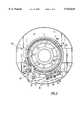
- FIG. 2is an enlarged section taken along the line 2--2 of FIG. 1;
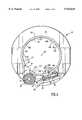
- FIG. 3is a section similar to FIG. 2 but showing only the base assembly
- FIG. 4is an exploded isometric of the base assembly
- FIG. 5is an enlarged view of detail "A" of FIG. 2.
- a router embodying the present inventionincludes a base assembly, generally designated 10, and a motor assembly, generally designated 12.
- the base assembly 10includes a generally annular base member 14 having an opening 15 (FIG. 4).
- the base assemblyincludes a cylindrical or tubular base member 16 supported by the annular sub-base member 14 in concentric relationship therewith.
- the cylindrical base member 16includes diametrically disposed mountings 18 supporting the usual handles 20 (the handles are shown only in FIG. 1).
- the cylindrical base member 16has a longitudinally extending slot or opening 22. Adjacent this slot, the cylindrical member 16 mounts clamp support members 24 and 25 having respective aligned bores 26 and 28.
- a pin 30is captured between ears 32 integral with an over-center clamp lever 34.
- the pin 30is received within an aperture 35 formed in one end of an adjusting screw 36.
- the screw 36is adapted to receive a washer 38 and a nut 40.
- the adjusting screw 36is received within the bores 26, 28 of the support members 24, 25 as seen in FIGS. 2 and 3. It is apparent that the clamp lever 34 may be actuated for compressing the opening 22 or for squeezing the cylindrical base member 16 into snug engagement with the motor housing 42. Also, the lever 34 may be released to expand the opening and to permit easy movement of the motor housing in the base assembly.
- the motor assembly 12includes a hollow motor housing 42 having a cylindrical portion 42a having an exterior surface 51 joining with a frusto-conical portion 42b which in turn joins with an enlarged, concentric annular formation 42c.
- the motor assembly 12also includes a cylindrical part 43 mounting a rocker switch 44.
- the part 43is connected to the part 42 by suitable fasteners (one such fastener is shown in FIG. 1 and designated 45).
- the motor assembly 12includes a cover 46.
- the coveris detachably connected to the part 43 by a plurality of fasteners (one such fastener is illustrated and designated 47).
- the motor housing 42is adapted to receive an electric motor (not shown) having an output shaft 49 mounting a collet 50.
- the collet 50is adapted to mount a suitable router bit (not shown) which projects through the opening 15 of the base member 14 for engagement with the work.
- the motoris preferably electric and includes the usual cord 54.
- the motoris actuated by the rocker switch 44.
- Other types of motorsmay be provided, such as a pneumatic motor.
- the cylinder 16 of the base assembly 10includes integral opposed lugs 58 and 60 joined by a wall 62 adjacent a rectangular aperture 64 (FIGS. 2 and 3) formed in the cylinder 16.
- Lugs 58 and 60include respective, vertically aligned apertures 66 and 68 rotatably receiving opposite ends of a vertical adjustment rod 70.
- the rod 70includes an external threaded formation 72 received within a threaded bore formed in an adjustment lever 74.
- the lever 74includes an integral latch formation 76.
- a spring 78has one end thereof received within a blind bore (FIG. 1) formed in the lever 74. The other end of the spring 78 engages a shoulder washer 82 (FIG. 2) which abuts the inside surface of the wall 62 thereby biasing the latch 76 to extend through the aperture 64.
- the rod 70mounts an indicator ring 84 and a knob 86.
- the knob 86 and indicator ring 84are mounted to the rod 70 for rotation therewith.
- the indicator ring 84 and the upper surface 58a of the lug 58may be provided with suitable indicia in the nature of a scale to indicate the rotary position of the rod 70. It will be apparent that rotation of the rod 70, by actuation of the knob 86, will cause vertical movement of the adjustment lever 74 upwardly or downwardly depending on the direction of rotation of the rod 70.
- the cylindrical member 42a of the motor housing 42includes three vertically aligned positioning notches. (One such notch 90 is shown in FIG. 2.) Each notch 90 is adapted to receive the latch 76 of the adjustment lever 74. Of course, any desired number of such vertically aligned notches or formations may be provided.
- the notchesmay be in the form of recesses in the cylinder 42a or in the form of openings through the cylinder 42a.
- the cylinder 42ais provided with three additional vertically aligned notches diametrically oppositely disposed to the notches 90.
- One such notch 90ais shown in FIG. 2.
- the motor assembly 12may be received within the base assembly in either of two rotary positions. As seen in FIG.
- the cylinder 42ais provided with two diametrically oppositely disposed, external recesses 92 each adapted to receive an alignment pin 94 mounted in the base cylinder 16. Engagement of one of the recesses 92 with the pin 94 will ensure that the notches 90 or 90a are in rotary alignment with the latch 76.
- the operatorwill release the over-center clamp 34 and slide the motor assembly 12 vertically to position a selected notch 90 or 90a in horizontal alignment with the latch 76 of the adjustment lever 74. Release of the adjustment lever 74 will permit the spring 78 to force the latch 76 into the selected notch 90 or 90a. Engagement of the latch 76 with one of the selected notches provides a coarse vertical adjustment.
- the operatorwill rotate the knob 86 in one direction or the other to rotate the rod 70 and thus move the adjustment lever 74 vertically upwardly or downwardly depending on the direction of rotation of the rod 70.
- This movement of the adjustment leverwill cause corresponding movement of the motor assembly 12 for establishing fine vertical adjustment of the motor and motor housing.
- the vertical adjustment mechanismis disclosed and claimed in application Ser. No. 08/963,918, filed Nov. 4, 1997, Attorney Docket No. 950801, and assigned to the assignee of the present application. The disclosure of that application is incorporated herein by reference.
- the clamp 34will be actuated to secure the motor assembly 12 to the base assembly 10.
- the slot 22defines spaced, axially extending faces 22a and 22b.
- the clamping mechanismis shown in its clamped position in both FIGS. 2 and 3. In the clamped position, the faces 22a and 22b will be spaced apart a distance determined by the position of the nut 40 on the screw 36. Stated another way, in the clamped position, the slot or opening is compressed.
- the nut 40provides a means to adjust the frictional engagement between the cylindrical base member 16 and the cylindrical motor housing 42.
- cylinder 16When the clamping lever 34 is moved to the unclamped position, cylinder 16 will expand to its relaxed circular state whereupon the faces 22a and 22b will be spaced from each other at a distance greater than the distance between these two faces when in the clamped position shown in FIGS. 2 and 3. Stated another way, the slot or opening is expanded when in the unclamped position.
- the inside diameter of the cylinder 16 when in its relaxed or unclamped configurationis slightly greater than the outside diameter of the cylindrical motor housing 42.
- the cylinder 16includes a longitudinally extending support rib 99 adjacent the face 22a defining planar support surface 100. Cylinder 16 also includes a longitudinally extending support rib 101 adjacent the face 22b defining a further planar support surface 102. Cylinder 16 includes another support rib 103 defining a further flat support surface 104. A final planar support surface 106 is defined by an inwardly extending support rib 105 formed on the cylinder 16.
- the support surfaces 104 and 106are spaced at approximately 120° from each other.
- the slot 22is approximately equidistant from the support surfaces 104 and 106 and thus the two surfaces 100 and 102 are also approximately equidistant from the surfaces 104 and 106. If the two surfaces 100 and 102 are considered to be a single surface, then a 3-point system is created where the support surfaces are very roughly 120° apart from one another.
- planar surfaces 100, 102, 104 and 106When the motor housing 42 is received within the cylinder 16 and when the clamping mechanism is moved to its clamped position, the planar surfaces 100, 102, 104 and 106 will engage the exterior surface 51 of the cylindrical motor portion 42a. Planar surfaces 100, 102, 104 and 106 establish tangential contact with the cylindrical motor part 42a. In this respect, attention is invited to FIG. 5 showing the cylindrical motor member 42a in engagement with the planar surface 104 of the rib 103 when the clamping lever 34 is in its clamped position. The tangential contact between the cylinder 42a and the planar support surface 104 establishes a longitudinally extending area of contact 108.
- the only areas of contact between the cylinder 16 of the base assembly and the cylindrical motor member 42a when in the clamped positionwill be those established by the four planar support surfaces 100, 102, 104 and 106.
- the other three planar support surfaceswill also provide tangential areas of contact.
- the axially extending support ribsall define arcuate open spaces 110, FIG. 5, between the inner surface 16a of the cylinder 16 and the exterior surface 51 of the motor housing cylinder 42a.
- the support surfaces 104 and 106establish a "V" formation thus constituting a V-block form of mounting for the cylindrical motor housing.
- the support surfaces 100 and 102serve only to press and secure the cylinder 42a of the motor housing 12 against the "V" formed by support surfaces 104 and 106.
- This mountingassures that the motor housing will not become cocked or canted when it is being clamped in the base assembly as it could be if the internal surface 16a were only cylindrical, i.e., if the cylindrical surface 16a did not include the various planar support surfaces. Accordingly, the router bit will be maintained in a precise perpendicular position to the plane of the annular base member 14 in all vertical positions of the motor assembly.
- concentricity of the collet 50will be maintained in all vertical positions of the motor assembly 12 because the motor is prevented from rotating within the base during vertical positioning by reason of the engagement of the pin 94 with one of the recesses 92. If it were necessary to rotate the motor housing to achieve vertical adjustment, as is the case with many prior art designs, any eccentricity of the collet with respect to the motor housing would introduce errors upon rotation of the motor housing.
- the cylinder 16includes additional inwardly extending ribs 111, 113 and 115, called tilt prevention ribs, forming further planar support surfaces 112, 114 and 116, respectively. These support surfaces do not contact the exterior surface of the motor housing 42 when the clamping mechanism is in its clamped position. This is so because the distance of each of the planar surfaces 112, 114 and 116 from the longitudinal central axis 118 of the cylinder 16 is greater than the distance of each of the planar surfaces 100, 102, 104 and 106 from the axis 118.
- the additional support surfacesare provided to support the motor housing when the clamping mechanism is in its unclamped position.
- a deflection limitation rib 120which also has a planar support surface 121, is positioned on the cylinder 16 approximately midway from the two support ribs 103 and 105.
- the planar surface 121is, like the surfaces 112, 114 and 116, at a greater distance from the longitudinal central axis 118 than the planar surfaces 100, 102, 104 and 106.
- the planar surface 121serves an important function should the clamp be adjusted for excessive clamping force.
- the section of the cylinder 16 between the support ribs 103 and 105may distort or deflect inwardly under the excessive clamping force causing the motor housing 42 and the base assembly 10 to fall out of the concentric relationship they were suppose to maintain.
- the addition of the deflection limitation rib 120 with its planar surfacecontrols the amount of allowed deflection of the cylinder 16 and hence the concentricity between the cylinder 16 and the motor housing 42 is maintained within acceptable limits.
Landscapes
- Life Sciences & Earth Sciences (AREA)
- Engineering & Computer Science (AREA)
- Mechanical Engineering (AREA)
- Wood Science & Technology (AREA)
- Forests & Forestry (AREA)
- Milling, Drilling, And Turning Of Wood (AREA)
Abstract
Description
Claims (15)
Priority Applications (1)
| Application Number | Priority Date | Filing Date | Title |
|---|---|---|---|
| US09/092,667US5913645A (en) | 1997-11-04 | 1998-06-05 | V-block mounting for fixed-base router with deflection limitation rib |
Applications Claiming Priority (2)
| Application Number | Priority Date | Filing Date | Title |
|---|---|---|---|
| US08/963,917US5853273A (en) | 1997-11-04 | 1997-11-04 | Fixed-base router with V-block mounting |
| US09/092,667US5913645A (en) | 1997-11-04 | 1998-06-05 | V-block mounting for fixed-base router with deflection limitation rib |
Related Parent Applications (1)
| Application Number | Title | Priority Date | Filing Date |
|---|---|---|---|
| US08/963,917Continuation-In-PartUS5853273A (en) | 1997-11-04 | 1997-11-04 | Fixed-base router with V-block mounting |
Publications (1)
| Publication Number | Publication Date |
|---|---|
| US5913645Atrue US5913645A (en) | 1999-06-22 |
Family
ID=46254097
Family Applications (1)
| Application Number | Title | Priority Date | Filing Date |
|---|---|---|---|
| US09/092,667Expired - Fee RelatedUS5913645A (en) | 1997-11-04 | 1998-06-05 | V-block mounting for fixed-base router with deflection limitation rib |
Country Status (1)
| Country | Link |
|---|---|
| US (1) | US5913645A (en) |
Cited By (31)
| Publication number | Priority date | Publication date | Assignee | Title |
|---|---|---|---|---|
| USD470375S1 (en) | 2002-09-04 | 2003-02-18 | Black & Decker Inc. | Router |
| USD470377S1 (en) | 2002-09-04 | 2003-02-18 | Black & Decker Inc. | Router |
| USD470736S1 (en) | 2002-09-04 | 2003-02-25 | Black & Decker Inc. | Router |
| USD473772S1 (en) | 2002-09-04 | 2003-04-29 | Black & Decker Inc. | Router |
| US20040005201A1 (en)* | 2002-07-03 | 2004-01-08 | Tomayko David C. | Router depth of cut adjustment |
| US6835032B1 (en)* | 2003-09-05 | 2004-12-28 | Credo Technology Corporation | Rotary power hand tool having a flexible handle and attachment system |
| US20050006000A1 (en)* | 2003-07-09 | 2005-01-13 | Credo Technology Corporation | Hybrid router |
| WO2005058542A1 (en)* | 2003-12-18 | 2005-06-30 | Robert Bosch Gmbh | Hand-held machine tool comprising an element that permits an approximate and precise axial setting |
| US20050232719A1 (en)* | 2004-04-19 | 2005-10-20 | Hitachi Koki Co., Ltd. | Portable electric tool |
| USD511079S1 (en)* | 2004-03-30 | 2005-11-01 | Hitachi Koki Co., Ltd. | Portable electric router |
| US6986369B1 (en) | 2002-11-12 | 2006-01-17 | Porter-Cable Corporation | Router height adjustment apparatus |
| US20060086219A1 (en)* | 1998-08-14 | 2006-04-27 | Milwaukee Electric Tool Corporation | Movable handle for a power tool |
| US20060086417A1 (en)* | 2002-10-15 | 2006-04-27 | Griffin Greg K | Router base securing mechanism |
| US20060102249A1 (en)* | 2003-05-01 | 2006-05-18 | Cooper Randy G | Router with drive shaft lock mechanism |
| US20060102248A1 (en)* | 2002-10-15 | 2006-05-18 | Cooper Randy G | Depth adjustment mechanism |
| US20060108024A1 (en)* | 2003-05-01 | 2006-05-25 | Cooper Randy G | Ergonomic router |
| US20060147286A1 (en)* | 2002-10-15 | 2006-07-06 | Porter-Cable Corporation | Switch assembly |
| US20060191597A1 (en)* | 2002-10-15 | 2006-08-31 | Black & Decker Inc. | Handle assembly |
| USD531871S1 (en) | 2005-06-16 | 2006-11-14 | Black & Decker Inc. | Router |
| USD546654S1 (en) | 2004-01-29 | 2007-07-17 | Black & Decker Inc. | Router with plunge base |
| US7275900B1 (en) | 2003-07-25 | 2007-10-02 | Black & Decker Inc. | Router elevating mechanism |
| US7316528B2 (en) | 2002-10-15 | 2008-01-08 | Black & Decker Inc. | Ergonomic router assembly |
| US20080156396A1 (en)* | 2002-10-15 | 2008-07-03 | Cooper Randy G | Handle assembly |
| US20080175683A1 (en)* | 2007-01-24 | 2008-07-24 | Chervon Limited | Power tool with cutting depth adjustment mechanism |
| US20080308188A1 (en)* | 2007-06-12 | 2008-12-18 | Black & Deker Inc. | Variable depth router and base |
| USD584590S1 (en) | 2004-10-29 | 2009-01-13 | Balck & Decker Inc. | Router |
| USD587977S1 (en)* | 2007-02-20 | 2009-03-10 | Gmca Pty Ltd | Base for a router power tool |
| USD588428S1 (en) | 2004-10-14 | 2009-03-17 | Black & Decker Inc. | Router |
| US7669620B2 (en) | 2000-08-11 | 2010-03-02 | Milwaukee Electric Tool Corporation | Router |
| US20100206434A1 (en)* | 2009-02-13 | 2010-08-19 | Credo Technology Corporation | Modular Router With Motor Clamp |
| US8087437B2 (en) | 2000-08-11 | 2012-01-03 | Techtronic Power Tools Technology Limited | Router |
Citations (13)
| Publication number | Priority date | Publication date | Assignee | Title |
|---|---|---|---|---|
| US4319860A (en)* | 1980-02-29 | 1982-03-16 | Black & Decker Inc. | Plunge type router |
| US4770573A (en)* | 1986-10-15 | 1988-09-13 | Ryobi Ltd. | Cutting depth adjusting mechanism of a router |
| US4938642A (en)* | 1988-09-02 | 1990-07-03 | Hitachi Koki Company, Limited | Portable electric router |
| US5074724A (en)* | 1991-02-28 | 1991-12-24 | Ryobi Motor Products Corp. | Split ring clamping arrangement |
| US5088865A (en)* | 1991-02-28 | 1992-02-18 | Ryobi Motor Products Corp. | Depth of cut adjustment mechansm for a router |
| US5094575A (en)* | 1990-03-15 | 1992-03-10 | Metabowerke Gmbh & Co. | Device for the fine adjustment of the cutting depth of a surface milling cutter |
| US5101875A (en)* | 1991-02-01 | 1992-04-07 | Ben Eckhold | Router base |
| US5117879A (en)* | 1991-09-13 | 1992-06-02 | Payne Leslie O | Split ring router mount apparatus |
| US5139061A (en)* | 1991-10-28 | 1992-08-18 | Neilson Patrick J | Router base table insert |
| US5143494A (en)* | 1991-10-18 | 1992-09-01 | Ryobi Motor Products Corp. | Depth of cut lock mechanism for a plunge type router |
| US5181813A (en)* | 1991-11-15 | 1993-01-26 | Ryobi Motor Products Corp. | Split ring lever clamping arrangement |
| US5188492A (en)* | 1991-02-28 | 1993-02-23 | Ryobi Motor Products Corporation | Split ring clamping arrangement |
| US5286147A (en)* | 1992-10-19 | 1994-02-15 | Francisco Escobedo | Depth gage adapter |
- 1998
- 1998-06-05USUS09/092,667patent/US5913645A/ennot_activeExpired - Fee Related
Patent Citations (13)
| Publication number | Priority date | Publication date | Assignee | Title |
|---|---|---|---|---|
| US4319860A (en)* | 1980-02-29 | 1982-03-16 | Black & Decker Inc. | Plunge type router |
| US4770573A (en)* | 1986-10-15 | 1988-09-13 | Ryobi Ltd. | Cutting depth adjusting mechanism of a router |
| US4938642A (en)* | 1988-09-02 | 1990-07-03 | Hitachi Koki Company, Limited | Portable electric router |
| US5094575A (en)* | 1990-03-15 | 1992-03-10 | Metabowerke Gmbh & Co. | Device for the fine adjustment of the cutting depth of a surface milling cutter |
| US5101875A (en)* | 1991-02-01 | 1992-04-07 | Ben Eckhold | Router base |
| US5074724A (en)* | 1991-02-28 | 1991-12-24 | Ryobi Motor Products Corp. | Split ring clamping arrangement |
| US5088865A (en)* | 1991-02-28 | 1992-02-18 | Ryobi Motor Products Corp. | Depth of cut adjustment mechansm for a router |
| US5188492A (en)* | 1991-02-28 | 1993-02-23 | Ryobi Motor Products Corporation | Split ring clamping arrangement |
| US5117879A (en)* | 1991-09-13 | 1992-06-02 | Payne Leslie O | Split ring router mount apparatus |
| US5143494A (en)* | 1991-10-18 | 1992-09-01 | Ryobi Motor Products Corp. | Depth of cut lock mechanism for a plunge type router |
| US5139061A (en)* | 1991-10-28 | 1992-08-18 | Neilson Patrick J | Router base table insert |
| US5181813A (en)* | 1991-11-15 | 1993-01-26 | Ryobi Motor Products Corp. | Split ring lever clamping arrangement |
| US5286147A (en)* | 1992-10-19 | 1994-02-15 | Francisco Escobedo | Depth gage adapter |
Cited By (53)
| Publication number | Priority date | Publication date | Assignee | Title |
|---|---|---|---|---|
| US7308764B2 (en)* | 1998-08-14 | 2007-12-18 | Milwaukee Electric Tool Corporation | Power tool with movable handle |
| US20060086219A1 (en)* | 1998-08-14 | 2006-04-27 | Milwaukee Electric Tool Corporation | Movable handle for a power tool |
| US20060174498A1 (en)* | 1998-08-14 | 2006-08-10 | Zeiler Jeffrey M | Movable handle for a power tool |
| US7497152B2 (en) | 1998-08-14 | 2009-03-03 | Milwaukee Electric Tool Corporation | Movable handle for a power tool |
| US20060117921A1 (en)* | 1998-08-14 | 2006-06-08 | Zeiler Jeffrey M | Movable handle for a power tool |
| US7669620B2 (en) | 2000-08-11 | 2010-03-02 | Milwaukee Electric Tool Corporation | Router |
| US8087437B2 (en) | 2000-08-11 | 2012-01-03 | Techtronic Power Tools Technology Limited | Router |
| US6779954B2 (en)* | 2002-07-03 | 2004-08-24 | Black & Decker, Inc. | Router depth of cut adjustment |
| US20040005201A1 (en)* | 2002-07-03 | 2004-01-08 | Tomayko David C. | Router depth of cut adjustment |
| USD470375S1 (en) | 2002-09-04 | 2003-02-18 | Black & Decker Inc. | Router |
| USD473772S1 (en) | 2002-09-04 | 2003-04-29 | Black & Decker Inc. | Router |
| USD470736S1 (en) | 2002-09-04 | 2003-02-25 | Black & Decker Inc. | Router |
| USD470377S1 (en) | 2002-09-04 | 2003-02-18 | Black & Decker Inc. | Router |
| US20060147286A1 (en)* | 2002-10-15 | 2006-07-06 | Porter-Cable Corporation | Switch assembly |
| US7654294B2 (en) | 2002-10-15 | 2010-02-02 | Black & Decker Inc. | Handle assembly |
| US20060102248A1 (en)* | 2002-10-15 | 2006-05-18 | Cooper Randy G | Depth adjustment mechanism |
| US20080156396A1 (en)* | 2002-10-15 | 2008-07-03 | Cooper Randy G | Handle assembly |
| US20060086417A1 (en)* | 2002-10-15 | 2006-04-27 | Griffin Greg K | Router base securing mechanism |
| US7451791B2 (en) | 2002-10-15 | 2008-11-18 | Black & Decker Inc. | Handle assembly |
| US7334614B2 (en) | 2002-10-15 | 2008-02-26 | Black & Decker Inc. | Depth adjustment mechanism |
| US7334613B2 (en)* | 2002-10-15 | 2008-02-26 | Black & Decker Inc. | Router base securing mechanism |
| US20060191597A1 (en)* | 2002-10-15 | 2006-08-31 | Black & Decker Inc. | Handle assembly |
| US7108464B2 (en) | 2002-10-15 | 2006-09-19 | Black & Decker Inc. | Switch assembly |
| US7316528B2 (en) | 2002-10-15 | 2008-01-08 | Black & Decker Inc. | Ergonomic router assembly |
| US6986369B1 (en) | 2002-11-12 | 2006-01-17 | Porter-Cable Corporation | Router height adjustment apparatus |
| US7490642B1 (en) | 2002-11-12 | 2009-02-17 | Black & Decker Inc. | Router height adjustment apparatus |
| US7089979B2 (en) | 2003-05-01 | 2006-08-15 | Black & Decker Inc. | Ergonomic router |
| US20060102249A1 (en)* | 2003-05-01 | 2006-05-18 | Cooper Randy G | Router with drive shaft lock mechanism |
| US20060108024A1 (en)* | 2003-05-01 | 2006-05-25 | Cooper Randy G | Ergonomic router |
| US20050006000A1 (en)* | 2003-07-09 | 2005-01-13 | Credo Technology Corporation | Hybrid router |
| US7290575B2 (en)* | 2003-07-09 | 2007-11-06 | Credo Technology Corporation | Hybrid router |
| US20080000546A1 (en)* | 2003-07-09 | 2008-01-03 | Freese John B | Hybrid router |
| US7578325B2 (en) | 2003-07-09 | 2009-08-25 | Credo Technology Corporation | Hybrid router |
| US7275900B1 (en) | 2003-07-25 | 2007-10-02 | Black & Decker Inc. | Router elevating mechanism |
| US7402008B2 (en) | 2003-07-25 | 2008-07-22 | Black & Decker Inc. | Router elevating mechanism |
| US6835032B1 (en)* | 2003-09-05 | 2004-12-28 | Credo Technology Corporation | Rotary power hand tool having a flexible handle and attachment system |
| US20070065245A1 (en)* | 2003-12-18 | 2007-03-22 | Carlson Carl C | Hand power tool |
| US7455488B2 (en) | 2003-12-18 | 2008-11-25 | Robert Bosch Gmbh | Hand power tool |
| WO2005058542A1 (en)* | 2003-12-18 | 2005-06-30 | Robert Bosch Gmbh | Hand-held machine tool comprising an element that permits an approximate and precise axial setting |
| USD546654S1 (en) | 2004-01-29 | 2007-07-17 | Black & Decker Inc. | Router with plunge base |
| USD511079S1 (en)* | 2004-03-30 | 2005-11-01 | Hitachi Koki Co., Ltd. | Portable electric router |
| US7121775B2 (en)* | 2004-04-19 | 2006-10-17 | Hitachi Koki Co., Ltd. | Portable electric tool |
| US20050232719A1 (en)* | 2004-04-19 | 2005-10-20 | Hitachi Koki Co., Ltd. | Portable electric tool |
| USD588428S1 (en) | 2004-10-14 | 2009-03-17 | Black & Decker Inc. | Router |
| USD584590S1 (en) | 2004-10-29 | 2009-01-13 | Balck & Decker Inc. | Router |
| USD531871S1 (en) | 2005-06-16 | 2006-11-14 | Black & Decker Inc. | Router |
| US7524151B2 (en)* | 2007-01-24 | 2009-04-28 | Chervon Limited | Power tool with cutting depth adjustment mechanism |
| US20080175683A1 (en)* | 2007-01-24 | 2008-07-24 | Chervon Limited | Power tool with cutting depth adjustment mechanism |
| USD587977S1 (en)* | 2007-02-20 | 2009-03-10 | Gmca Pty Ltd | Base for a router power tool |
| US7946318B2 (en) | 2007-06-12 | 2011-05-24 | Black & Decker Inc. | Variable depth router and base |
| US20080308188A1 (en)* | 2007-06-12 | 2008-12-18 | Black & Deker Inc. | Variable depth router and base |
| US20100206434A1 (en)* | 2009-02-13 | 2010-08-19 | Credo Technology Corporation | Modular Router With Motor Clamp |
| US8066041B2 (en)* | 2009-02-13 | 2011-11-29 | Robert Bosch Gmbh | Modular router with motor clamp |
Similar Documents
| Publication | Publication Date | Title |
|---|---|---|
| US5913645A (en) | V-block mounting for fixed-base router with deflection limitation rib | |
| US5853273A (en) | Fixed-base router with V-block mounting | |
| US5853274A (en) | Vertical adjustment mechanism for fixed-base router | |
| US5265511A (en) | Controlled axial position hinge assembly | |
| US5088865A (en) | Depth of cut adjustment mechansm for a router | |
| US3443479A (en) | Depth adjustment for power tool | |
| US5078557A (en) | Limit stops for a router depth of cut adjustment mechanism | |
| US5074724A (en) | Split ring clamping arrangement | |
| US6758123B2 (en) | Bevel angle detent system for a compound miter saw | |
| US4152961A (en) | Radial saw | |
| JP4840927B2 (en) | Cutting tilt & depth detent system | |
| US20030110646A1 (en) | Adjustable reciprocating saw | |
| US7402008B2 (en) | Router elevating mechanism | |
| US4549727A (en) | Lazy susan vise | |
| US20030024366A1 (en) | Bevel stop for cutting device | |
| US4958544A (en) | Radial arm saw | |
| US6588111B2 (en) | Undercut saw with central height adjustment | |
| EP0140145A1 (en) | Indexing arrangement for the table of a chop saw | |
| US4335768A (en) | Depth of cut adjustment mechanism | |
| CA1259787A (en) | Cutter head assembly for power planer | |
| US4474512A (en) | Milling tool with adjustable cutter bit | |
| US6053678A (en) | Rotary tool holder with a balance device | |
| US20180326611A1 (en) | Router base having adjustable mounting slots | |
| US4482118A (en) | Adjusting base for geodetic instruments | |
| US7066695B1 (en) | Router mounting system |
Legal Events
| Date | Code | Title | Description |
|---|---|---|---|
| AS | Assignment | Owner name:S-B POWER TOOL COMPANY, ILLINOIS Free format text:ASSIGNMENT OF ASSIGNORS INTEREST;ASSIGNOR:COFFEY, JOHN R.;REEL/FRAME:009239/0216 Effective date:19980522 | |
| FEPP | Fee payment procedure | Free format text:PAYOR NUMBER ASSIGNED (ORIGINAL EVENT CODE: ASPN); ENTITY STATUS OF PATENT OWNER: LARGE ENTITY | |
| FPAY | Fee payment | Year of fee payment:4 | |
| FEPP | Fee payment procedure | Free format text:PAYER NUMBER DE-ASSIGNED (ORIGINAL EVENT CODE: RMPN); ENTITY STATUS OF PATENT OWNER: LARGE ENTITY Free format text:PAYOR NUMBER ASSIGNED (ORIGINAL EVENT CODE: ASPN); ENTITY STATUS OF PATENT OWNER: LARGE ENTITY | |
| AS | Assignment | Owner name:S-B POWER TOOL CORPORATION, ILLINOIS Free format text:SECRETARY'S CERTIFICATE;ASSIGNOR:S- B POWER TOOL COMPANY;REEL/FRAME:014609/0996 Effective date:20020703 Owner name:CREDO TECHNOLOGY CORPORATION, DELAWARE Free format text:ASSIGNMENT OF ASSIGNORS INTEREST;ASSIGNOR:ROBERT BOSCH TOOL CORPORATION;REEL/FRAME:014615/0215 Effective date:20030101 Owner name:ROBERT BOSCH TOOL CORPORATION, ILLINOIS Free format text:COMBINED MERGER AND CHANGE OF NAME;ASSIGNOR:S-B POWER TOOL CORPORATION;REEL/FRAME:014615/0197 Effective date:20021227 | |
| FEPP | Fee payment procedure | Free format text:PAYOR NUMBER ASSIGNED (ORIGINAL EVENT CODE: ASPN); ENTITY STATUS OF PATENT OWNER: LARGE ENTITY Free format text:PAYER NUMBER DE-ASSIGNED (ORIGINAL EVENT CODE: RMPN); ENTITY STATUS OF PATENT OWNER: LARGE ENTITY | |
| FPAY | Fee payment | Year of fee payment:8 | |
| REMI | Maintenance fee reminder mailed | ||
| LAPS | Lapse for failure to pay maintenance fees | ||
| STCH | Information on status: patent discontinuation | Free format text:PATENT EXPIRED DUE TO NONPAYMENT OF MAINTENANCE FEES UNDER 37 CFR 1.362 | |
| FP | Lapsed due to failure to pay maintenance fee | Effective date:20110622 |