US5913287A - Method and apparatus for enhancing the fluidization of fuel particles in coal burning boilers and fluidized bed combustion - Google Patents
Method and apparatus for enhancing the fluidization of fuel particles in coal burning boilers and fluidized bed combustionDownload PDFInfo
- Publication number
- US5913287A US5913287AUS09/140,235US14023598AUS5913287AUS 5913287 AUS5913287 AUS 5913287AUS 14023598 AUS14023598 AUS 14023598AUS 5913287 AUS5913287 AUS 5913287A
- Authority
- US
- United States
- Prior art keywords
- screen
- boiler
- particles
- screens
- fuel
- Prior art date
- Legal status (The legal status is an assumption and is not a legal conclusion. Google has not performed a legal analysis and makes no representation as to the accuracy of the status listed.)
- Expired - Fee Related
Links
- 239000002245particleSubstances0.000titleclaimsabstractdescription49
- 239000000446fuelSubstances0.000titleclaimsabstractdescription28
- 238000002485combustion reactionMethods0.000titleclaimsabstractdescription22
- 238000000034methodMethods0.000titleclaimsdescription10
- 239000003245coalSubstances0.000titleabstractdescription25
- 238000005243fluidizationMethods0.000titledescription2
- 230000002708enhancing effectEffects0.000title1
- 239000002594sorbentSubstances0.000claimsabstractdescription17
- 239000007787solidSubstances0.000claimsabstractdescription12
- 239000000567combustion gasSubstances0.000claimsabstractdescription3
- 239000000203mixtureSubstances0.000claimsdescription10
- 239000000463materialSubstances0.000claimsdescription3
- 238000004064recyclingMethods0.000claimsdescription2
- 239000011236particulate materialSubstances0.000claims2
- 230000001846repelling effectEffects0.000claims1
- 239000007789gasSubstances0.000abstractdescription12
- 238000005201scrubbingMethods0.000abstractdescription6
- 238000002156mixingMethods0.000abstractdescription2
- 239000011802pulverized particleSubstances0.000abstractdescription2
- 235000019738LimestoneNutrition0.000description4
- 239000002956ashSubstances0.000description4
- 239000010881fly ashSubstances0.000description4
- 239000006028limestoneSubstances0.000description4
- UGFAIRIUMAVXCW-UHFFFAOYSA-NCarbon monoxideChemical compound[O+]#[C-]UGFAIRIUMAVXCW-UHFFFAOYSA-N0.000description3
- JTJMJGYZQZDUJJ-UHFFFAOYSA-NphencyclidineChemical classC1CCCCN1C1(C=2C=CC=CC=2)CCCCC1JTJMJGYZQZDUJJ-UHFFFAOYSA-N0.000description3
- 239000005997Calcium carbideSubstances0.000description2
- 229910002091carbon monoxideInorganic materials0.000description2
- 239000003546flue gasSubstances0.000description2
- 238000011065in-situ storageMethods0.000description2
- 238000012423maintenanceMethods0.000description2
- CLZWAWBPWVRRGI-UHFFFAOYSA-Ntert-butyl 2-[2-[2-[2-[bis[2-[(2-methylpropan-2-yl)oxy]-2-oxoethyl]amino]-5-bromophenoxy]ethoxy]-4-methyl-n-[2-[(2-methylpropan-2-yl)oxy]-2-oxoethyl]anilino]acetateChemical compoundCC1=CC=C(N(CC(=O)OC(C)(C)C)CC(=O)OC(C)(C)C)C(OCCOC=2C(=CC=C(Br)C=2)N(CC(=O)OC(C)(C)C)CC(=O)OC(C)(C)C)=C1CLZWAWBPWVRRGI-UHFFFAOYSA-N0.000description2
- 235000008733Citrus aurantifoliaNutrition0.000description1
- 229910000831SteelInorganic materials0.000description1
- NINIDFKCEFEMDL-UHFFFAOYSA-NSulfurChemical compound[S]NINIDFKCEFEMDL-UHFFFAOYSA-N0.000description1
- 235000011941Tilia x europaeaNutrition0.000description1
- 238000005299abrasionMethods0.000description1
- 230000015572biosynthetic processEffects0.000description1
- 239000003034coal gasSubstances0.000description1
- 238000001816coolingMethods0.000description1
- 230000007423decreaseEffects0.000description1
- 239000010459dolomiteSubstances0.000description1
- 229910000514dolomiteInorganic materials0.000description1
- 230000000694effectsEffects0.000description1
- 238000000265homogenisationMethods0.000description1
- 238000002347injectionMethods0.000description1
- 239000007924injectionSubstances0.000description1
- 239000004571limeSubstances0.000description1
- 230000013011matingEffects0.000description1
- 230000003014reinforcing effectEffects0.000description1
- 239000010959steelSubstances0.000description1
- 229910052717sulfurInorganic materials0.000description1
- 239000011593sulfurSubstances0.000description1
Images


Classifications
- F—MECHANICAL ENGINEERING; LIGHTING; HEATING; WEAPONS; BLASTING
- F23—COMBUSTION APPARATUS; COMBUSTION PROCESSES
- F23M—CASINGS, LININGS, WALLS OR DOORS SPECIALLY ADAPTED FOR COMBUSTION CHAMBERS, e.g. FIREBRIDGES; DEVICES FOR DEFLECTING AIR, FLAMES OR COMBUSTION PRODUCTS IN COMBUSTION CHAMBERS; SAFETY ARRANGEMENTS SPECIALLY ADAPTED FOR COMBUSTION APPARATUS; DETAILS OF COMBUSTION CHAMBERS, NOT OTHERWISE PROVIDED FOR
- F23M9/00—Baffles or deflectors for air or combustion products; Flame shields
- F23M9/06—Baffles or deflectors for air or combustion products; Flame shields in fire-boxes
- F—MECHANICAL ENGINEERING; LIGHTING; HEATING; WEAPONS; BLASTING
- F22—STEAM GENERATION
- F22B—METHODS OF STEAM GENERATION; STEAM BOILERS
- F22B31/00—Modifications of boiler construction, or of tube systems, dependent on installation of combustion apparatus; Arrangements or dispositions of combustion apparatus
- F—MECHANICAL ENGINEERING; LIGHTING; HEATING; WEAPONS; BLASTING
- F23—COMBUSTION APPARATUS; COMBUSTION PROCESSES
- F23C—METHODS OR APPARATUS FOR COMBUSTION USING FLUID FUEL OR SOLID FUEL SUSPENDED IN A CARRIER GAS OR AIR
- F23C6/00—Combustion apparatus characterised by the combination of two or more combustion chambers or combustion zones, e.g. for staged combustion
- F23C6/04—Combustion apparatus characterised by the combination of two or more combustion chambers or combustion zones, e.g. for staged combustion in series connection
- F23C6/045—Combustion apparatus characterised by the combination of two or more combustion chambers or combustion zones, e.g. for staged combustion in series connection with staged combustion in a single enclosure
- F23C6/047—Combustion apparatus characterised by the combination of two or more combustion chambers or combustion zones, e.g. for staged combustion in series connection with staged combustion in a single enclosure with fuel supply in stages
- F—MECHANICAL ENGINEERING; LIGHTING; HEATING; WEAPONS; BLASTING
- F23—COMBUSTION APPARATUS; COMBUSTION PROCESSES
- F23J—REMOVAL OR TREATMENT OF COMBUSTION PRODUCTS OR COMBUSTION RESIDUES; FLUES
- F23J7/00—Arrangement of devices for supplying chemicals to fire
- F—MECHANICAL ENGINEERING; LIGHTING; HEATING; WEAPONS; BLASTING
- F23—COMBUSTION APPARATUS; COMBUSTION PROCESSES
- F23C—METHODS OR APPARATUS FOR COMBUSTION USING FLUID FUEL OR SOLID FUEL SUSPENDED IN A CARRIER GAS OR AIR
- F23C2201/00—Staged combustion
- F23C2201/10—Furnace staging
- F23C2201/101—Furnace staging in vertical direction, e.g. alternating lean and rich zones
- F—MECHANICAL ENGINEERING; LIGHTING; HEATING; WEAPONS; BLASTING
- F23—COMBUSTION APPARATUS; COMBUSTION PROCESSES
- F23M—CASINGS, LININGS, WALLS OR DOORS SPECIALLY ADAPTED FOR COMBUSTION CHAMBERS, e.g. FIREBRIDGES; DEVICES FOR DEFLECTING AIR, FLAMES OR COMBUSTION PRODUCTS IN COMBUSTION CHAMBERS; SAFETY ARRANGEMENTS SPECIALLY ADAPTED FOR COMBUSTION APPARATUS; DETAILS OF COMBUSTION CHAMBERS, NOT OTHERWISE PROVIDED FOR
- F23M2900/00—Special features of, or arrangements for combustion chambers
- F23M2900/09061—Moving baffles, e.g. rotating baffles, for creating vortices
Definitions
- This inventionrelates to a method and apparatus for comminuting coal particles, by themselves or in mixture with a sorbent, in a coal burning boiler and more particularly to such a method and apparatus in which the larger particles are recycled and made finer for more efficient burning and flame scrubbing by sorbent particles to effect reduction of SO x and NO x .
- coal for use in such boilersis generally prepared in roller mills which produce coal of 70%-200 mesh size from 2" lump coal feed. The smaller the particle size, the higher the combustion rate, many larger size particles escaping complete or even partial combustion in the main boiler combustion zone.
- Micronized sorbentslimestone, dolomite may be used for flame scrubbing the in situ formed SO x and NO x in the boiler, utilizing micronized or pulverized coal as a fuel.
- the fuel and sorbentmay be in the form of pulverized particles or lump solids.
- the device and method of the present inventionovercomes the shortcomings of the prior art by employing fast rotating screens having wide mesh openings(4-10 mesh) in the boiler. These screens when used in a high velocity gas stream act to repel slower moving larger particles, thereby effecting their recycling. Further, the high speed rotating screens create vertical spiral vortexes thereabove by splitting the high velocity gas columns passing therethrough and concurrently twisting these split columns of gas. Passage of the upwardly gas-solid particulate stream through the rotating screens does not cause a pressure drop in such high velocity stream. Twisting of the air columns during said passage through the fast rotating screens produces a horizontal velocity component. This component causes a homogenization of the upwardly streaming gas and particulate solid mix, thereby providing an increased heat output in the boiler.
- a first rotating screenis mounted in the boiler above the main combustion zone of the boiler and recycles the larger particles of the fuel, sorbent and ash back to said combustion zone.
- the smaller particles which pass through the rotating screenare comminuted in spiral vortices formed above such screen.
- a second high speed rotating screenis located above the first screen. This second screen mixes the burning coal and sorbent particles and gas in this region and further comminutes said particles.
- FIG. 1is a schematic drawing illustrating a preferred embodiment of the invention
- FIG. 2is a schematic drawing illustrating the operation of the preferred embodiment
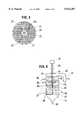
- FIG. 3is a schematic drawing illustrating one of the screens of the preferred embodiment
- FIG. 4is a schematic drawing of a second embodiment of the invention.
- FIG. 5is a schematic drawing of a third embodiment of the invention.
- FIG. 6is a schematic view of a fourth embodiment of the invention.
- FIG. 7is a schematic view of a fifth embodiment of the invention.
- FIGS. 1-3a preferred embodiment of the invention is illustrated.
- Circular screens 11 and 12are fixedly attached to shaft 13 which is rotatably driven by drive shaft 14.
- Shaft 14is rotatably supported on bearing 15 which are mounted on the top wall of boiler 17. Further radial support for the drive shaft is provided by means of a guide ring structure 16 which is attached to the wall of the boiler and which has a circular sleeve portion 16a which surrounds the shaft 14.
- Shaft 14is driven at a speed of 1,500-10,000 rpm.
- FIG. 3the structure of screens 11 and 12 is illustrated.
- An abrasion resistant steel screen structure 20 having wide mesh openings(4-10 mesh size)is fixedly supported in holder frame 21.
- Radial reinforcing spokes 22are attached at one end thereof to holder frame 21 and at the other end to central deflector disk 24.
- Formed in the center of deflector disk 24is a hub 25 which is adapted to fit over shaft 13.
- a keyway 24ais formed in the hub of the deflector disk 24 which fits into a mating key slot formed in shaft 13. As shown in FIG. 2, any particles still remaining pass through convection heat transfer surfaces 35 for cooling prior to their exit through outlet 34.
- Coal particles mixed with airare fed through fuel lines 27 into boiler 17. Before entering the boiler the air and coal particles are heated by means of burners 28 which are mounted on the walls of the boiler and serve to ignite and partially combust the fuel. This particle-air mixture enters the main combustion zone 29 of the boiler.
- the boilerhas a bottom outlet 30 through which ash is disposed.
- Upper screen 12is located beneath the burnout zone 32 of the boiler to fluidize the burning fine coal-gas mixture, or a mix of co-burning coal and scrubbing sorbent.
- Fuel for the reburn process for NO x reductionis fed into the boiler through inlets 33 with overfire air being fed in through inlet 37.
- the operation of the device of the inventionis as follows.
- the underside of rotating screen 11repels the larger and slower burning particles that escape from combustion zone 29, such particles being recycled for complete burnout.
- the smaller glowing coal particles suspended in the combustion gasespass through screen 11 and are exposed to the comminuting action of the spiral vortexes 33 generated above screen 11.
- Such particles, having been rendered soft at the flame temperature of the main combustion zone,are thus reduced in size and can pass through screen 12 into burnout zone 32.
- the particles in burnout zone 32are further comminuted and mixed with the gas by the action of the spiral vortexes formed in this zone. Particles that still remain are fed out of the boiler through outlet 34 for further processing or collection.
- Lower screen 11also provides the mixing and fluidization for injected sorbent in the boiler for the flame scrubbing of the in situ SO x and NO x .
- the sorbentis injected either through fuel lines 27 as a mixture of fuel and sorbent or through reburn fuel line 33 as sorbent itself.
- FIG. 4a second embodiment of the invention is illustrated, this embodiment being generally similar to the first embodiment but being adapted to operate with a boiler in which the reburn fuel is injected into the boiler to reduce NO x levels.
- reburn fuelis introduced into the boiler through inlet 40 after having been heated by burner 28 through partial combustion.
- An additional rotating screen 42 similar to the screens 11 and 12is provided under the "reburn zone" 43. Screen 42 comminutes the burning fuel particles and recycles the larger particles to the main combustion zone 29. This provides for a more effective use of the reburn fuel and decreases the NO x produced in the boiler in addition to increasing the thermal yield and lowering maintenance costs.
- FIG. 5a third embodiment of the invention is illustrated.
- This embodimentis generally similar to the first embodiment but utilizes low NO x cell burners. Fuel is fed into main combustion zone 29 through inlets 27.
- the rotating screen 11operates to recycle the larger unburned coal particles and also comminutes the fly ash emitted.
- the second rotating screen 12provides additional comminution of the burning fuel and fly ash particles and homogenizes the gases in the burnout zone 32.
- FIG. 6a further embodiment of the invention generally similar to the first embodiment is shown.
- This embodimentconstitutes a pressurized circulating fluidized bed system and employs a pair of rotating screens 11 and 12 as in the first embodiment.
- Screen 11is positioned above fluidized bed 47 and recycles the coal, ash and sorbent particles that escape the turbulent bed back into bed 47.
- the fuel and ash particles and gas which pass through rotating screens 11 and 12are comminuted by the vertical spiral vortexes above the screens and are carried by the gas stream into the hot cyclone 48 from where the solid particulates and tar are recycled into fluidized bed 47.
- FIG. 7a further embodiment of the invention generally similar to the first embodiment is shown.
- This embodimentis one that operates at atmospheric pressure and is a circulating fluidized bed system. Only a single fast rotating screen 11 is employed along with a pair of hot cyclones 48.
- the single rotating screen 11operates as the previous embodiments to recycle larger particles back into fluidized bed 47 and to comminute the smaller particles passed through the screen in the spiral vortexes formed above the screen.
- High sulfur coal and limestonemay be fed into the boiler through inlets 27. The particles are passed into hot cyclones 48 and from these cyclones the residual solids and tar are recycled into the fluidized bed 47.
Landscapes
- Engineering & Computer Science (AREA)
- Mechanical Engineering (AREA)
- General Engineering & Computer Science (AREA)
- Chemical & Material Sciences (AREA)
- Combustion & Propulsion (AREA)
- Physics & Mathematics (AREA)
- Thermal Sciences (AREA)
- Treating Waste Gases (AREA)
Abstract
Description
Claims (10)
Priority Applications (1)
| Application Number | Priority Date | Filing Date | Title |
|---|---|---|---|
| US09/140,235US5913287A (en) | 1998-01-14 | 1998-08-26 | Method and apparatus for enhancing the fluidization of fuel particles in coal burning boilers and fluidized bed combustion |
Applications Claiming Priority (2)
| Application Number | Priority Date | Filing Date | Title |
|---|---|---|---|
| US7143298P | 1998-01-14 | 1998-01-14 | |
| US09/140,235US5913287A (en) | 1998-01-14 | 1998-08-26 | Method and apparatus for enhancing the fluidization of fuel particles in coal burning boilers and fluidized bed combustion |
Publications (1)
| Publication Number | Publication Date |
|---|---|
| US5913287Atrue US5913287A (en) | 1999-06-22 |
Family
ID=26752216
Family Applications (1)
| Application Number | Title | Priority Date | Filing Date |
|---|---|---|---|
| US09/140,235Expired - Fee RelatedUS5913287A (en) | 1998-01-14 | 1998-08-26 | Method and apparatus for enhancing the fluidization of fuel particles in coal burning boilers and fluidized bed combustion |
Country Status (1)
| Country | Link |
|---|---|
| US (1) | US5913287A (en) |
Cited By (4)
| Publication number | Priority date | Publication date | Assignee | Title |
|---|---|---|---|---|
| US20020017450A1 (en)* | 2000-08-03 | 2002-02-14 | Ernest Csendes | Method and apparatus for separating impurities from a liquid |
| US20030196578A1 (en)* | 2001-04-23 | 2003-10-23 | Logan Terry J. | Processes and systems for using biomineral by-products as a fuel and for NOx removal at coal burning power plants |
| WO2006101475A1 (en)* | 2005-03-16 | 2006-09-28 | Csendes, Catharine | Method and apparatus for separating impurities from a liquid |
| CN106402847A (en)* | 2016-09-21 | 2017-02-15 | 黑龙江省电力科学研究院 | Burner arrangement structure with tertiary air and SOFA air arranged alternately |
Citations (4)
| Publication number | Priority date | Publication date | Assignee | Title |
|---|---|---|---|---|
| US4203391A (en)* | 1978-07-31 | 1980-05-20 | The Babcock & Wilcox Company | Fluidized bed fuel feeder |
| US5193490A (en)* | 1991-09-03 | 1993-03-16 | The Babcock & Wilcox Company | Cyclonic mixing and combustion chamber for circulating fluidized bed boilers |
| US5343830A (en)* | 1993-03-25 | 1994-09-06 | The Babcock & Wilcox Company | Circulating fluidized bed reactor with internal primary particle separation and return |
| US5730071A (en)* | 1996-01-16 | 1998-03-24 | The Babcock & Wilcox Company | System to improve mixing and uniformity of furnace combustion gases in a cyclone fired boiler |
- 1998
- 1998-08-26USUS09/140,235patent/US5913287A/ennot_activeExpired - Fee Related
Patent Citations (4)
| Publication number | Priority date | Publication date | Assignee | Title |
|---|---|---|---|---|
| US4203391A (en)* | 1978-07-31 | 1980-05-20 | The Babcock & Wilcox Company | Fluidized bed fuel feeder |
| US5193490A (en)* | 1991-09-03 | 1993-03-16 | The Babcock & Wilcox Company | Cyclonic mixing and combustion chamber for circulating fluidized bed boilers |
| US5343830A (en)* | 1993-03-25 | 1994-09-06 | The Babcock & Wilcox Company | Circulating fluidized bed reactor with internal primary particle separation and return |
| US5730071A (en)* | 1996-01-16 | 1998-03-24 | The Babcock & Wilcox Company | System to improve mixing and uniformity of furnace combustion gases in a cyclone fired boiler |
Cited By (5)
| Publication number | Priority date | Publication date | Assignee | Title |
|---|---|---|---|---|
| US20020017450A1 (en)* | 2000-08-03 | 2002-02-14 | Ernest Csendes | Method and apparatus for separating impurities from a liquid |
| US6869502B2 (en)* | 2000-08-03 | 2005-03-22 | General Grinding Corporation | Method and apparatus for separating impurities from a liquid |
| US20030196578A1 (en)* | 2001-04-23 | 2003-10-23 | Logan Terry J. | Processes and systems for using biomineral by-products as a fuel and for NOx removal at coal burning power plants |
| WO2006101475A1 (en)* | 2005-03-16 | 2006-09-28 | Csendes, Catharine | Method and apparatus for separating impurities from a liquid |
| CN106402847A (en)* | 2016-09-21 | 2017-02-15 | 黑龙江省电力科学研究院 | Burner arrangement structure with tertiary air and SOFA air arranged alternately |
Similar Documents
| Publication | Publication Date | Title |
|---|---|---|
| JP2782384B2 (en) | Integrated low NOx angle combustion system | |
| AU2003212026B2 (en) | Nox-reduced combustion of concentrated coal streams | |
| US4655148A (en) | Method of introducing dry sulfur oxide absorbent material into a furnace | |
| US5732894A (en) | Micronization apparatus and method | |
| AU762789B2 (en) | Method of operating a tangential firing system | |
| US4246853A (en) | Fuel firing method | |
| CA1172913A (en) | Mixer for dual register burner | |
| GB1590635A (en) | Coal burning arrangement | |
| US6244200B1 (en) | Low NOx pulverized solid fuel combustion process and apparatus | |
| EP0737290B1 (en) | Low emission and low excess air system | |
| SK278148B6 (en) | Method of mixed combustion of coal and device for realization of this method | |
| JPS62196522A (en) | Heat recovery method from fluidized bed and its equipment | |
| CA1092897A (en) | Fuel firing method | |
| JP2003240227A (en) | Solid fuel burner and method of burning solid fuel burner | |
| US7004089B2 (en) | Combined fluidized bed and pulverized coal combustion method | |
| US5913287A (en) | Method and apparatus for enhancing the fluidization of fuel particles in coal burning boilers and fluidized bed combustion | |
| US6234093B1 (en) | Furnace | |
| US4485747A (en) | Reducing pollutant emissions by fines removal | |
| KR910006233B1 (en) | Apparatus and method for pulverizing and burning solid fuel | |
| EP0852686B1 (en) | Method and reactor for processing of fuels having a wide particle size distribution | |
| RU2627757C2 (en) | Layer boiler with vertical swirling-type furnace | |
| SU1456701A1 (en) | Boiler furnace | |
| JP2721375B2 (en) | Crusher | |
| US20090123883A1 (en) | Swirling-type furnace operating method and a swirling-type furnace | |
| JPS61143610A (en) | Multi-stage fluidized-bed boiler |
Legal Events
| Date | Code | Title | Description |
|---|---|---|---|
| AS | Assignment | Owner name:CSENDES, CATHERINE, CALIFORNIA Free format text:SPOUSAL PROPERTY ORDER;ASSIGNOR:CSENDES, CATHERINE SURVIVING SPOUSE OF ERNEST CSENDES (DECEASED);REEL/FRAME:013868/0478 Effective date:20020705 | |
| FPAY | Fee payment | Year of fee payment:4 | |
| AS | Assignment | Owner name:GENERAL GRINDING CORP., CALIFORNIA Free format text:ASSIGNMENT OF ASSIGNORS INTEREST;ASSIGNOR:CSENDES, CATHARINE V.;REEL/FRAME:014128/0190 Effective date:20031114 | |
| AS | Assignment | Owner name:TNP, ENTERPRISES, INC., TEXAS Free format text:ASSIGNMENT OF ASSIGNORS INTEREST;ASSIGNOR:GENERAL GRINDING CORPORATION;REEL/FRAME:017366/0391 Effective date:20050318 | |
| FPAY | Fee payment | Year of fee payment:8 | |
| SULP | Surcharge for late payment | Year of fee payment:7 | |
| REMI | Maintenance fee reminder mailed | ||
| LAPS | Lapse for failure to pay maintenance fees | ||
| LAPS | Lapse for failure to pay maintenance fees | Free format text:PATENT EXPIRED FOR FAILURE TO PAY MAINTENANCE FEES (ORIGINAL EVENT CODE: EXP.); ENTITY STATUS OF PATENT OWNER: SMALL ENTITY | |
| STCH | Information on status: patent discontinuation | Free format text:PATENT EXPIRED DUE TO NONPAYMENT OF MAINTENANCE FEES UNDER 37 CFR 1.362 | |
| FP | Lapsed due to failure to pay maintenance fee | Effective date:20110622 |